US9366031B2 - Eccentrically loaded structural members and methods of forming the same - Google Patents
Eccentrically loaded structural members and methods of forming the same Download PDFInfo
- Publication number
- US9366031B2 US9366031B2 US14/887,715 US201514887715A US9366031B2 US 9366031 B2 US9366031 B2 US 9366031B2 US 201514887715 A US201514887715 A US 201514887715A US 9366031 B2 US9366031 B2 US 9366031B2
- Authority
- US
- United States
- Prior art keywords
- load
- structural member
- compressive
- example embodiment
- eccentricity
- Prior art date
- Legal status (The legal status is an assumption and is not a legal conclusion. Google has not performed a legal analysis and makes no representation as to the accuracy of the status listed.)
- Active
Links
- 238000000034 method Methods 0.000 title claims abstract description 20
- 238000006073 displacement reaction Methods 0.000 claims description 31
- 238000005452 bending Methods 0.000 description 29
- 238000004519 manufacturing process Methods 0.000 description 20
- 230000006835 compression Effects 0.000 description 15
- 238000007906 compression Methods 0.000 description 15
- 239000000463 material Substances 0.000 description 9
- 238000012360 testing method Methods 0.000 description 8
- 238000013461 design Methods 0.000 description 7
- 238000003754 machining Methods 0.000 description 3
- 230000007246 mechanism Effects 0.000 description 3
- 238000013459 approach Methods 0.000 description 2
- 230000000712 assembly Effects 0.000 description 2
- 238000000429 assembly Methods 0.000 description 2
- 230000008901 benefit Effects 0.000 description 2
- 230000015572 biosynthetic process Effects 0.000 description 2
- 238000012986 modification Methods 0.000 description 2
- 230000004048 modification Effects 0.000 description 2
- 239000000853 adhesive Substances 0.000 description 1
- 230000001070 adhesive effect Effects 0.000 description 1
- 244000309464 bull Species 0.000 description 1
- 230000008859 change Effects 0.000 description 1
- 230000003247 decreasing effect Effects 0.000 description 1
- 230000001419 dependent effect Effects 0.000 description 1
- 238000010348 incorporation Methods 0.000 description 1
- 239000000203 mixture Substances 0.000 description 1
- 230000036316 preload Effects 0.000 description 1
- 230000008569 process Effects 0.000 description 1
Images


Classifications
-
- E—FIXED CONSTRUCTIONS
- E04—BUILDING
- E04C—STRUCTURAL ELEMENTS; BUILDING MATERIALS
- E04C3/00—Structural elongated elements designed for load-supporting
- E04C3/30—Columns; Pillars; Struts
-
- F—MECHANICAL ENGINEERING; LIGHTING; HEATING; WEAPONS; BLASTING
- F16—ENGINEERING ELEMENTS AND UNITS; GENERAL MEASURES FOR PRODUCING AND MAINTAINING EFFECTIVE FUNCTIONING OF MACHINES OR INSTALLATIONS; THERMAL INSULATION IN GENERAL
- F16F—SPRINGS; SHOCK-ABSORBERS; MEANS FOR DAMPING VIBRATION
- F16F7/00—Vibration-dampers; Shock-absorbers
- F16F7/12—Vibration-dampers; Shock-absorbers using plastic deformation of members
-
- F—MECHANICAL ENGINEERING; LIGHTING; HEATING; WEAPONS; BLASTING
- F16—ENGINEERING ELEMENTS AND UNITS; GENERAL MEASURES FOR PRODUCING AND MAINTAINING EFFECTIVE FUNCTIONING OF MACHINES OR INSTALLATIONS; THERMAL INSULATION IN GENERAL
- F16F—SPRINGS; SHOCK-ABSORBERS; MEANS FOR DAMPING VIBRATION
- F16F9/00—Springs, vibration-dampers, shock-absorbers, or similarly-constructed movement-dampers using a fluid or the equivalent as damping medium
-
- F—MECHANICAL ENGINEERING; LIGHTING; HEATING; WEAPONS; BLASTING
- F16—ENGINEERING ELEMENTS AND UNITS; GENERAL MEASURES FOR PRODUCING AND MAINTAINING EFFECTIVE FUNCTIONING OF MACHINES OR INSTALLATIONS; THERMAL INSULATION IN GENERAL
- F16C—SHAFTS; FLEXIBLE SHAFTS; ELEMENTS OR CRANKSHAFT MECHANISMS; ROTARY BODIES OTHER THAN GEARING ELEMENTS; BEARINGS
- F16C7/00—Connecting-rods or like links pivoted at both ends; Construction of connecting-rod heads
- F16C7/06—Adjustable connecting-rods
-
- F—MECHANICAL ENGINEERING; LIGHTING; HEATING; WEAPONS; BLASTING
- F16—ENGINEERING ELEMENTS AND UNITS; GENERAL MEASURES FOR PRODUCING AND MAINTAINING EFFECTIVE FUNCTIONING OF MACHINES OR INSTALLATIONS; THERMAL INSULATION IN GENERAL
- F16F—SPRINGS; SHOCK-ABSORBERS; MEANS FOR DAMPING VIBRATION
- F16F2230/00—Purpose; Design features
- F16F2230/16—Purpose; Design features used in a strut, basically rigid
-
- Y—GENERAL TAGGING OF NEW TECHNOLOGICAL DEVELOPMENTS; GENERAL TAGGING OF CROSS-SECTIONAL TECHNOLOGIES SPANNING OVER SEVERAL SECTIONS OF THE IPC; TECHNICAL SUBJECTS COVERED BY FORMER USPC CROSS-REFERENCE ART COLLECTIONS [XRACs] AND DIGESTS
- Y10—TECHNICAL SUBJECTS COVERED BY FORMER USPC
- Y10T—TECHNICAL SUBJECTS COVERED BY FORMER US CLASSIFICATION
- Y10T29/00—Metal working
- Y10T29/49—Method of mechanical manufacture
- Y10T29/49616—Structural member making
Definitions
- Fuse structural members are elongated members which must fail at predetermined loads to avoid damage to surrounding mechanical elements, while still maintaining sufficient strength and rigidity to efficiently and safely transmit forces at sub-fuse loads.
- the successful design of a fuse load is complicated by the variable degree in bending of the member as the load increases.
- the failure point and direction of failure is driven by the presence of manufacturing eccentricities and tolerances, material variations and cross sectional shape throughout the length of the member.
- Fuse loads are the predetermined loads that cause fuse structural members to fail prior to damaging surrounding elements. Fuse loads in compression are usually accomplished by the use of either a shear pin or spring mechanism. In the case of the shear pin the load that causes the pin to shear in compression will also shear at the same load in tension. In the case of a spring, the assembly does not fail but begins to displace according to Hooks Law once the spring preload is surpassed. Therefore, the spring continues to add force as displacement increases. Both shear pin and spring mechanism fuse loads are expensive to manufacture, add complexity to designs and have limitations to their applications. In weight or fatigue critical applications, such as aerospace, the use of a spring mechanism may be impractical.
- Typical rod assembly design for compression relies heavily on Euler and Johnson-Euler equations to determine safe working loads. These equations establish the theoretical lowest compressive loads where columns, as for example structural rod assemblies and struts, can be expected to buckle. A theoretical column with no load eccentricity, subject to an increasing compressive force, would eventually fail due to compressive yielding. This compressive yielding creates a local instability that will eventually lead to bending and subsequent buckling. Initial yielding failure would occur at an unpredictable location and cause instability in an unpredictable direction.
- Structural members that experience significant bending during compressive loads may gain structural support if they rest against neighboring elements.
- a column 10 that gains support 12 ( FIG. 1 b ) at mid span will have a buckling load 8 times higher than column 10 supported by pins 14 ( FIG. 1 c ).
- a column 10 that gains transverse support at its ends 16 by support members 18 ( FIG. 1 a ) will have a buckling load 4 times higher than a column supported only by pins ( FIG. 1 c ). Even slight support gained from surrounding elements can have large impacts on the magnitude of the expected compressive failure load.
- an elongated member has an elongated body having a load central longitudinal axis.
- a first fitting is coupled to a first end of the elongated body for applying a compressive load to the elongated body along a first axis offset from said load central longitudinal axis.
- a second fitting is coupled to a second end of the elongated body opposite the first end for applying a compressive load to the elongated body along a second axis offset from the load central longitudinal axis.
- another elongated member in another example embodiment, is provided.
- the elongated member includes an elongated body having an outer surface defined about a central longitudinal axis. The outer surface defines a first recess section about at least a portion of the body.
- a first fitting is coupled to a first end of the elongated body for applying a compressive load to the elongated body along the central longitudinal axis.
- a second fitting coupled to a second end of the elongated body opposite the first end for applying a compressive load to the elongated body along said central longitudinal axis.
- a further elongated member in yet another example embodiment, includes an elongated body having an outer surface about a central longitudinal axis. The elongated body is bent defining having an arcuate shape. A first fitting is coupled to a first end of the elongated body for applying a compressive load to the elongated body. A second fitting is coupled to a second end of the elongated body opposite the first end for applying a compressive load to the elongated body.
- a method of tuning a structural member, including an eccentricity, to a fuse load includes subjecting the structural member to a compressive axial load by compressive axial displacement, and stopping the compressive axial displacement when the compressive axial load drops to a level of the desired fuse load.
- the structural member is tuned to the fuse load when the compressive axial load has plastically deformed the structural member.
- a method of tuning a structural member to a fuse load includes subjecting the structural member to a side load sufficient to bend the structural member in a desired direction, subjecting the structural member to a compressive axial load by compressive axial displacement, stopping the compressive axial load, holding the axial displacement, and removing the side load, when the structural member has plastically deformed at mid-span or proximate mid-span.
- the method also includes continuing to subject the structural member to a compressive axial load by compressive axial displacement, and to stopping the compressive axial displacement when the compressive axial load drops to a level of the desired fuse load.
- the structural member is tuned to the fuse load when the compressive axial load has plastically deformed the structural member.
- FIGS. 1 a , 1 b and 1 c are schematic side views depicting different columns under compressive loading.
- FIG. 2 a is a side view of an example embodiment structural member including end fittings.
- FIG. 2 b is an end view of the structural member depicted in FIG. 2 a with a fitting.
- FIG. 3 a is a side view of another example structural member without fittings.
- FIGS. 3 b and 3 c are an end view and a side view of an example embodiment insert for mounting on the structural member shown in FIG. 3 a.
- FIG. 3 d is a side view of another example structural member.
- FIG. 4 is an end view of another example embodiment insert.
- FIG. 5 is a partial side view of an example embodiment structural member including an example embodiment fitting.
- FIG. 6 is a partial side view of another example embodiment structural member with an integral fitting.
- FIG. 7 is a side view of another example embodiment structural member including fittings.
- FIG. 8 is a side view of another example embodiment structural member without fittings.
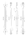
- FIGS. 9 a and 9 b are side views at 90° to each other of another example embodiment structural member.
- FIGS. 10 a and 10 b are side views at 90° to each other of yet another example embodiment structural member.
- FIGS. 11 a and 11 b are side views at 90° to each other of a further example embodiment structural member.
- FIGS. 12 a and 12 b are side views at 90° to each other of yet a further example embodiment structural member.
- FIGS. 13 and 14 are graphs of load vs displacement data from straight tubes with 0.015 inch and 0.030 inch eccentricity, respectively.
- FIG. 15 is a flow chart of an example embodiment approach for tuning a fuse load of an example embodiment structural member with eccentricity.
- FIG. 16 is a flow chart of an example embodiment approach for tuning a fuse load of a structural member without eccentricity or with just manufacturing eccentricity.
- Applicants have developed fuse elongated structural member embodiments which greatly increase the repeatability and reliability of the compressive failure load and the resulting direction of structural member deformation during bending and subsequent failure.
- a “load central longitudinal axis” as used herein refers to an axis of an elongated structure where when the structure is loaded under compression along this load central longitudinal axis the structure will crumple and fail at the compressive yield strength of the material from which it is made.
- the load central longitudinal axis is the same as the structures central longitudinal axis.
- Most structures have some manufacturing eccentricity built in (i.e., eccentricity caused by manufacturing imperfections) and as a result a compressive load applied along its central longitudinal axis leads to buckling of the structure at a compressive load lower than the compressive yield strength of the material that the structure is made of.
- Fuse loads which are higher in tension than in compression can also be accommodated by incorporation of a shear pin for the tensile fuse load and eccentric bending for the compressive fuse load.
- the embodiments of this disclosure offer a less expensive and more efficient means to achieve fuse loads in compression while still allowing for tensile fuse loads at a greater force if required.
- Load eccentricity can be introduced in several ways.
- load eccentricity is introduced by offset of connecting threads between end fitting and structural member, offset of internal threads of a structural member insert, offset of pin connections in end fitting threaded to or otherwise attached to structural member, or offset of pin connections in structural member; or pre-curved or pre-bent structural member.
- the eccentricity of the example embodiments structures is such that the compressive loading axis, i.e., the axis along which the load is applied is offset from the structure's central longitudinal axis when the structure has no eccentricity and is offset from the load central axis when structure has manufacturing eccentricity.
- Gyration I min A of the structural member. This dictates the member's propensity to bend while under compression. Members with slenderness ratios high enough to be considered long and slender under Euler definition require lower load eccentricities to ensure predictable bending. Designs become less effective as slenderness ratios decrease and required eccentricities to ensure bending increase.
- Eccentricity is the maximum distance between the structure's central longitudinal axis and the compression load axis as measured perpendicularly from the central longitudinal axis along the body of the structural member.
- a first fuse member (i.e., structural member) 21 has long slender tube 10 by Euler definition having eccentric bore 20 for accepting a fitting 23 into said eccentric bore on one or both ends 22 , as for example shown in FIGS. 2 a and 2 b .
- the eccentric end bore 20 has a central longitudinal axis 39 offset from a central longitudinal axis 35 of the structural member 21 .
- the loading to the fuse member is applied through the fittings.
- each eccentric bore 20 has internal threads 24 onto which is threaded a corresponding fitting. Eccentric threading of tube is formed, machined or tapped off-center from the axis of the tube 10 .
- one fitting is threaded in a clockwise direction, while the other fitting is threaded in a counter-clockwise direction.
- rotating the tube in one direction while holding the fittings will cause the fittings to thread into their corresponding bores, while rotating the tube in the opposite direction, while holding the fittings will cause the fittings to unthread from their corresponding bores.
- each fitting may be locked in place with a corresponding lock nut which is threaded onto the threads of the fitting and fastened against the corresponding end of the tube.
- each fitting has an opening 27 through which a load will be applied and a shaft 29 which is received in the end bore of the tube.
- the load is applied by a pin inserted in the opening 27 .
- Structural members which are loaded via pins or other members inserted into the fitting openings 27 are sometimes referred to as “pin-to-pin connected structural members”.
- the opening 27 has a center 31 in line with the longitudinal central axis 33 of the shaft 29 .
- the central longitudinal axis 33 of the shaft is co-axial with the central longitudinal axis 39 of the end bore.
- the distance 37 between the central longitudinal axis 35 and the central longitudinal axis 33 of the end bore as measured perpendicularly from the central longitudinal axis 37 is the loading eccentricity.
- enough material should be present at the connection interface of the end fitting and the tube body to allow for both the full formation of threads and sufficient material wall thickness to cope with the additional stresses and moments imparted by the eccentric loading.
- a long slender tube 32 by Euler definition, has thin wall geometry and concentric end bores 32 ( FIG. 3 a ) for receiving inserts 34 ( FIGS. 3 b and 3 c ).
- the end bores 32 are threaded, i.e., they have an internal threaded surface 36 for receiving a threaded portion 38 of a corresponding insert 34 .
- at least one insert 34 is received into one end bore.
- the inserts 34 have an eccentrically formed hole 40 .
- the eccentrically formed hole is formed on the insert off-center.
- the off-center hole 40 in each insert is formed by machining.
- the eccentrically formed hole has internal threads 42 for receiving threads of a fitting.
- the eccentrically formed holes 40 on each insert are aligned, i.e., the have the same central axis.
- a keyway slot 44 is formed on each insert end face 46 .
- the eccentrically formed hole 40 has a central axis 50 offset from the central axis 52 of the insert by a distance 54 , such that a diameter 56 of the eccentrically formed hole is offset in parallel from a diameter 58 of the insert by the same distance.
- each keyway slot is aligned along the diameter 56 of the eccentrically formed hole 40 .
- the keyway slot of one insert is aligned to be parallel and on the same side of the long slender tube load central axis with the keyway slot of the other insert, and the inserts are oriented locked in place as for example by using wrenching flats formed on an outer surface of the insert or a nut also threaded on the outer surface of the insert.
- An adhesive may be used to adhere the insert to the long slender tube.
- both inserts are oriented with their keyway slots parallel, the eccentrically formed holes of both inserts are coaxially aligned and then held through swaging of the tube body material against the threads of the insert, thus locking the insert's position and orientation with the tube body.
- one fitting is threaded in a clockwise direction, while the other fitting is threaded in a counter-clockwise direction into their corresponding inserts.
- rotating the tube in one direction while holding the fittings will cause the fittings to thread into their corresponding bores, while rotating the tube in the opposite direction, while holding the fittings will cause the fittings to unthread from their corresponding bores.
- each fitting has an opening 27 through which a load will be applied and a shaft 29 which is received in the end bore of the tube.
- the opening 27 has a center 31 in line with a longitudinal central axis 33 of the shaft 29 .
- the distance 54 is the loading eccentricity.
- an outer diameter of the tube is reduced at mid-span 60 so as to lower the strength of the tube at mid-span and thus adjusting the failure point of the desired fuse load ( FIG. 3 d ).
- inserts 62 may be used to strengthen the area while providing more area for eccentrically located threads ( FIG. 4 ).
- a structural member such as a tube or strut 70 is used with concentric end bores for receiving fittings, each fitting 72 having an off-centered opening 74 , as for example shown in FIG. 5 .
- the opening 74 receives the load applying member as for example a bearing cartridge, or a pin, or a bushing or a spherical ball.
- the axes 76 of the end fitting openings 74 through a diameter or a center of the openings and are offset by a distance 78 from the central axis 80 of the structural member 70 .
- the axes of the openings 74 are aligned with each other.
- the fitting(s) 72 is integrally formed with the structural member 70 , as for example shown in FIG. 6 .
- the distance 75 is the loading eccentricity.
- a structural member 70 such as a tube or strut is formed in into a bent shape or is pre-bent into a bent arcuate shape where a mid-span section 82 of the tube is offset from the end sections or extremities 84 .
- a plane 86 through said mid-section center which is parallel to a plane 88 through the centers of the fitting openings 27 , is spaced a greater distance from the plane 88 than a plane 90 through the centers of the ends 91 of the structural member.
- the plane 86 is sufficiently offset from the plane 88 by a distance 84 to induce desired bending and a predictable failure load when under compressive loading via the fittings.
- the distance 76 defines the loading eccentricity.
- the structural member is plastically deformed at or proximate its mid-span.
- a structural member such as a tube or strut has a straight mid-section 92 as for example shown in FIG. 8 and has swaged end sections 94 ending in end sections 95 , each defining an end bore 96 for receiving a fitting.
- the mid-section is a cylindrical member having a central longitudinal axis 98
- each end section is also cylindrical having a central longitudinal axis 100 .
- both end sections have the same central longitudinal axis 100 which is offset in parallel by a distance 99 from the mid-section central longitudinal axis 98 . The distance 99 is the loading eccentricity.
- a structural member such as a tube or strut 110 is formed, as for example by machining, or by other methods, to have a second lower moment of inertia about a cross-sectional axis in line with the desired axis of bending 112 ( FIGS. 9 a and 10 a ) and a higher second moment of inertia about the cross-sectional axis 114 which is perpendicular to the desired axis of bending 112 ( FIGS. 9 b and 10 b ).
- FIGS. 9 a and 10 a This, in one example embodiment as shown in FIGS.
- FIGS. 9 a , 9 b , 10 a , and 10 b is accomplished by making the structural member thinner at its mid-section 116 when viewed along the desired bending axis 112 as shown in FIGS. 9 b and 10 b and thicker when viewed along cross-sectional axis 114 as shown in FIGS. 10 a and 10 b .
- the mid-section 116 is thinner than the end sections 118 .
- the central longitudinal axis 120 is co-linear with the central longitudinal axis 122 of the end sections.
- eccentric loading is allowed by machining or forming the structural member (e.g., the tube or strut) 110 , by removing material or by recessing the member at one side of the mid-section 116 defining a recessed surface 130 .
- a load central longitudinal axis 133 of the recessed structure is offset by a distance 135 from load axis 132 .
- a longitudinal axis 132 along which a load will be applied is closer to the recessed surface than to surface 134 opposite the recessed surface as measured along a direction 136 through and perpendicular the longitudinal axis 132 .
- the distance 135 is the loading eccentricity.
- structural member will bend toward the recessed section when under compression.
- the non-recessed portion of the mid-section in example embodiments is circular in cross-section. In other embodiments such non-recessed section may have other cross-sectional shapes as for example polygonal, elliptical, etc.
- FIGS. 2 a to 8 and FIGS. 11 a to 12 b loading eccentricity is provided that exceeds any manufacturing eccentricity present and/or is such as to cause bending in a direction other than the direction the structure would have failed under compressive loading due to its manufacturing eccentricity.
- Pin-to-pin connected structural members are designed and manufactured with the least amount of load eccentricity possible.
- Structural members that incorporate the eccentric loading as in the example embodiments of the present disclosure allow for predictable failure loads and directions of failure. This enables the design of structural members that are able to fail at highly consistent loads.
- the load is applied along a load axis that is offset from a central longitudinal axis of the elongated slender member.
- This load axis may be parallel to the central longitudinal axis of the member. In some embodiments, this load axis is not parallel to the central longitudinal axis but is offset at each end of the structural member by the same distance from the central longitudinal axis.
- the elongated slender member may not be cylindrical and may have other shapes, as for example, it may be an I-beam in cross-section, which is symmetric about a symmetry plane through its central longitudinal axis. In the embodiments where a section of the central longitudinal member is removed or recessed, as for example shown in FIGS. 9 a to 11 b , the structural member may not be symmetrical about such a symmetry plane.
- moments are not transmitted through the structural member, e,g, the tube or strut, to the next connecting element.
- Example structural members having on load eccentricity induced bending are able to have higher fuse loads in tension than in compression.
- the fuse load is driven by the bending failure and in tension by the weakest cross section along the member.
- Example embodiment elongated structures have an eccentricity rate equal to the manufacturing eccentricity rate (R) plus an additional eccentricity rate.
- the additional eccentricity rate is at 0.0001 inch/inch of length.
- it is 0.0002 inch/inch of length.
- it is 0.0003 inch/inch of length.
- it is at least 0.0004 inch/inch of length.
- it is at least 0.0005 inch/inch of length.
- the slenderness ratio of the structural member is equal to or greater than
- the compression load axis (i.e., the axis along which the compressive load is applied) is parallel with the load central longitudinal axis.
- Applicants have also discovered that they can tune the example embodiment structural members to fail at a desired fuse load. To do so, Applicants first subject the structural member to a compressive axial load via controlled displacement (block 152 , FIG. 15 ) while the ends of the structural member are constrained as they would be constrained during actual use. For example, in many aircraft embodiments, the structural members are pin to pin constrained. In other words, the ends of the structural member are rotatable about their corresponding pins to which they are coupled. By subjecting the structural member to a compressive axial load by displacement in the compressive direction, the load would reach an ultimate strength, and the load would then begin to drop upon further displacement.
- the axial displacement is stopped (block 156 ). If not, the axial displacement continues until the axial load is dropped to the level of a desired fuse load (block 154 ). Once the axial load is stopped, the axial load is removed (block 158 ), the structural member is evaluated to confirm that it is plastically deformed (block 160 ). Many methods well known in the art can be used to confirm plastic formation. One example method may be to inspect the bent structural member to see if it has stayed in the bent state. That would be an indication of plastic deformation. If plastically deformed, then the structural member is tuned to the desired fuse load and should fail at or slightly above such fuse load. If the structural member is not plastically deformed, then the structural member needs to be redesigned (e.g. the eccentricity or slenderness of the structural member may need to be modified) (block 161 ).
- the structural member is subjected to a side load sufficient to overcome the manufacturing eccentricities and induce bending to a desired direction (block 162 , FIG. 16 ) while constrained as they would during actual use.
- the structural member is then subjected to an increase in compressive axial load by controlled compressive displacement (block 164 ). During such displacement, the load would reach an ultimate strength and the load would then begin to drop upon further displacement.
- the displacement is continued until the structural member is plastically deformed at its mid-span (block 166 ). As discussed previously, plastic deformation can be easily determined using well known methods.
- the loading is stopped and the axial displacement is held (block 168 ).
- the side load is then removed (block 170 ) and the axial displacement is then resumed in the compressive direction (block 172 ).
- the load continues to decrease (block 174 )
- the axial displacement is continually applied until the axial compressive load drops to a level that is equal to the desired fuse load (block 176 ).
- the axial displacement is stopped (block 178 ) and the axial load is removed (block 180 ).
- the member has further plastically deformed (block 182 ) over the plastic deformation as per block 166 , then the member is tuned to the desired fuse load. If not, then the structural member needs to be redesigned (e.g.
- the eccentricity or slenderness of the structural member may need to be modified). If the applied load is not decreasing (block 174 ) then the structural member is continuously subjected to an increase in compressive loading by controlled displacement (block 164 ) until the member is plastically deformed at the mid-span (block 166 ). If the side load has already been removed (block 184 ), then the axial displacement is continued until the axial compressive load drops to a level equal to the desired fuse load level (block 176 ). In such case, the axial displacement is stopped (block 178 ) and the load is removed (block 180 ) and the further plastic deformation is confirmed (block 182 ). If the plastic deformation is confirmed, the structural member is now tuned to the desired fuse load. If not, then the structural member needs to be redesigned (block 184 ).
- Applicants have discovered that they can design elongated structural members to bend in, or generally in, a predetermined direction and to fail at a, or generally at a, predetermined load by incorporating sufficient eccentricity to such members. This is especially important when such structural members are used in aircraft where unpredicted failure as well as unpredicted bending direction can cause damage to and or jam surrounding structures and parts.
- a method is provided for designing or forming elongated structural member that fail at a, or generally at a, predetermined load and in, or generally in, a predetermined direction by offsetting the compression load axis relative to the structural member and load central longitudinal axis, as described herein. In example embodiments, such offset is in parallel.
Abstract
Description
is greater or equal to 0.5, wherein:
-
- L=Length of the elongated body
- Le=Effective Length of the elongated body
- Imin=Minimum Second Moment of Inertia of the elongated body
- A=Cross sectional Area of the elongated body
- rmin=Minimum Radius of Gyration of
-
- σy=Yield Stress of the elongated body
- E=Modulus of Elasticity of the elongated body.
is greater or equal to 0.5,
wherein:
-
- L=Length of the elongated body
- Le=Effective Length of the elongated body
- Imin=Minimum Second Moment of Inertia of the elongated body
- A=Cross sectional Area of the elongated body
- rmin=Minimum Radius of Gyration of
-
- σy=Yield Stress of the elongated body
- E=Modulus of Elasticity of the elongated body.
are considered long and slender by Euler definition, where,
L=Length
Le=Effective Length (varies by end fixity condition)
-
- An infinite number of effective lengths exist for any given Length due to variations in fixity and loading conditions.
- Examples of some common effective lengths with concentrated axial loading:
-
- (Common effective lengths and methods of calculating less common effective lengths for various loading and boundary conditions of structures is provided in Jones, Robert M. Buckling of Bars, Plates, and Shells. Blacksburg, Va.; Bull Ridge Publishing, 2006, the contents of which are fully incorporated herein by reference.)
Imin=Minimum Second Moment of Inertia
A=Cross sectional Area
rmin=Minimum Radius of
- (Common effective lengths and methods of calculating less common effective lengths for various loading and boundary conditions of structures is provided in Jones, Robert M. Buckling of Bars, Plates, and Shells. Blacksburg, Va.; Bull Ridge Publishing, 2006, the contents of which are fully incorporated herein by reference.)
σy=Yield Stress
E=Modulus of Elasticity
of the structural member. This dictates the member's propensity to bend while under compression. Members with slenderness ratios high enough to be considered long and slender under Euler definition require lower load eccentricities to ensure predictable bending. Designs become less effective as slenderness ratios decrease and required eccentricities to ensure bending increase.
Although such structural members may require greater induced eccentricity as compared to that required to overcome the manufacturing eccentricity alone. Thus, in an example embodiment, the slenderness ratio of the structural member is equal to or greater than
where R is the manufacturing eccentricity rate. In an example embodiment, R is 0.0005 or less. For intermediate structural members where
In any of the aforementioned embodiments, the compression load axis (i.e., the axis along which the compressive load is applied) is parallel with the load central longitudinal axis.
Claims (3)
Priority Applications (1)
| Application Number | Priority Date | Filing Date | Title |
|---|---|---|---|
| US14/887,715 US9366031B2 (en) | 2013-04-10 | 2015-10-20 | Eccentrically loaded structural members and methods of forming the same |
Applications Claiming Priority (3)
| Application Number | Priority Date | Filing Date | Title |
|---|---|---|---|
| US201361810653P | 2013-04-10 | 2013-04-10 | |
| US14/250,309 US9194126B2 (en) | 2013-04-10 | 2014-04-10 | Eccentrically loaded structural members and methods of forming the same |
| US14/887,715 US9366031B2 (en) | 2013-04-10 | 2015-10-20 | Eccentrically loaded structural members and methods of forming the same |
Related Parent Applications (1)
| Application Number | Title | Priority Date | Filing Date |
|---|---|---|---|
| US14/250,309 Division US9194126B2 (en) | 2013-04-10 | 2014-04-10 | Eccentrically loaded structural members and methods of forming the same |
Publications (2)
| Publication Number | Publication Date |
|---|---|
| US20160040429A1 US20160040429A1 (en) | 2016-02-11 |
| US9366031B2 true US9366031B2 (en) | 2016-06-14 |
Family
ID=51685802
Family Applications (2)
| Application Number | Title | Priority Date | Filing Date |
|---|---|---|---|
| US14/250,309 Active US9194126B2 (en) | 2013-04-10 | 2014-04-10 | Eccentrically loaded structural members and methods of forming the same |
| US14/887,715 Active US9366031B2 (en) | 2013-04-10 | 2015-10-20 | Eccentrically loaded structural members and methods of forming the same |
Family Applications Before (1)
| Application Number | Title | Priority Date | Filing Date |
|---|---|---|---|
| US14/250,309 Active US9194126B2 (en) | 2013-04-10 | 2014-04-10 | Eccentrically loaded structural members and methods of forming the same |
Country Status (1)
| Country | Link |
|---|---|
| US (2) | US9194126B2 (en) |
Families Citing this family (3)
| Publication number | Priority date | Publication date | Assignee | Title |
|---|---|---|---|---|
| US10612254B2 (en) | 2017-02-28 | 2020-04-07 | Supportworks, Inc. | Systems and methods for wall support and/or straightening |
| CN108519759B (en) * | 2018-04-12 | 2020-11-03 | 佛山金皇宇企业孵化器有限公司 | Length compensation method for saw-cut section of cutting machine tool |
| US11536352B2 (en) * | 2018-09-26 | 2022-12-27 | The Boeing Company | Drive train linkage and method therefor |
Citations (22)
| Publication number | Priority date | Publication date | Assignee | Title |
|---|---|---|---|---|
| US1900763A (en) | 1930-05-14 | 1933-03-07 | Thomas A Rowe | Silo |
| US2388309A (en) | 1942-10-23 | 1945-11-06 | John S Curtiss | Fuse protector device |
| US3754609A (en) | 1970-09-30 | 1973-08-28 | Smith International | Drill string torque transmission sleeve |
| US3934450A (en) * | 1974-08-12 | 1976-01-27 | General Steel Industries, Inc. | Method and apparatus for bending elongated members |
| US4059816A (en) * | 1975-11-20 | 1977-11-22 | Mcgraw-Edison Company | Electrical loadbreak fuse and canister assembly |
| SU1350538A1 (en) | 1986-07-10 | 1987-11-07 | Институт Проблем Прочности Ан Усср | Method of determining modulus of normal elasticity |
| US4763878A (en) | 1986-03-03 | 1988-08-16 | Robert S. Abraham | Apparatus for jacking basement walls |
| US5175972A (en) * | 1984-07-02 | 1993-01-05 | Hasnain Investments (P) Limited | Sleeved compression member |
| JPH09317085A (en) * | 1996-05-24 | 1997-12-09 | Dai Ichi High Frequency Co Ltd | Metal pipe having locally irregular shape and its manufacture |
| US5862003A (en) * | 1995-06-23 | 1999-01-19 | Saif; Muhammad T. A. | Micromotion amplifier |
| US6257190B1 (en) | 1998-08-28 | 2001-07-10 | Terry Glyn Linebarger | Cam operating system |
| US6357190B1 (en) * | 1999-12-13 | 2002-03-19 | Frank R. Florentine | Wall bracing method and system therefor |
| US6957515B1 (en) * | 2003-03-14 | 2005-10-25 | Hatfield Mark D | Device for holding a workpiece adjacent a ceiling support |
| US20060073712A1 (en) * | 2004-10-05 | 2006-04-06 | Ephraim Suhir | Apparatus and test device for the application and measurement of prescribed, predicted and controlled contact pressure on wires |
| US20060260219A1 (en) * | 2005-05-20 | 2006-11-23 | Marlin Riddle | Stud framing brace |
| US20060260217A1 (en) | 2002-10-18 | 2006-11-23 | Black Robert D | Constructional unit |
| US20100205876A1 (en) * | 2007-05-15 | 2010-08-19 | Constantin Christopoulus | Cast structural yielding fuse |
| US20110249353A1 (en) | 2010-04-09 | 2011-10-13 | David White | Intentionally Buckled Columns and Columns with Displacement Controls that Form Optical Shapes |
| US8136317B1 (en) | 2009-12-23 | 2012-03-20 | Mccown Matthew S | Assembly for straightening a basement's wall |
| US20130292349A1 (en) | 2012-05-02 | 2013-11-07 | William Bucklew | Adjustable curtain rod assembly |
| US20140000999A1 (en) | 2012-07-02 | 2014-01-02 | Airbus Operations Sas | Connecting rod incorporating an energy absorber |
| US20140360106A1 (en) | 2013-06-10 | 2014-12-11 | Jack A. Sawyers | Wall straightening support assembly |
-
2014
- 2014-04-10 US US14/250,309 patent/US9194126B2/en active Active
-
2015
- 2015-10-20 US US14/887,715 patent/US9366031B2/en active Active
Patent Citations (22)
| Publication number | Priority date | Publication date | Assignee | Title |
|---|---|---|---|---|
| US1900763A (en) | 1930-05-14 | 1933-03-07 | Thomas A Rowe | Silo |
| US2388309A (en) | 1942-10-23 | 1945-11-06 | John S Curtiss | Fuse protector device |
| US3754609A (en) | 1970-09-30 | 1973-08-28 | Smith International | Drill string torque transmission sleeve |
| US3934450A (en) * | 1974-08-12 | 1976-01-27 | General Steel Industries, Inc. | Method and apparatus for bending elongated members |
| US4059816A (en) * | 1975-11-20 | 1977-11-22 | Mcgraw-Edison Company | Electrical loadbreak fuse and canister assembly |
| US5175972A (en) * | 1984-07-02 | 1993-01-05 | Hasnain Investments (P) Limited | Sleeved compression member |
| US4763878A (en) | 1986-03-03 | 1988-08-16 | Robert S. Abraham | Apparatus for jacking basement walls |
| SU1350538A1 (en) | 1986-07-10 | 1987-11-07 | Институт Проблем Прочности Ан Усср | Method of determining modulus of normal elasticity |
| US5862003A (en) * | 1995-06-23 | 1999-01-19 | Saif; Muhammad T. A. | Micromotion amplifier |
| JPH09317085A (en) * | 1996-05-24 | 1997-12-09 | Dai Ichi High Frequency Co Ltd | Metal pipe having locally irregular shape and its manufacture |
| US6257190B1 (en) | 1998-08-28 | 2001-07-10 | Terry Glyn Linebarger | Cam operating system |
| US6357190B1 (en) * | 1999-12-13 | 2002-03-19 | Frank R. Florentine | Wall bracing method and system therefor |
| US20060260217A1 (en) | 2002-10-18 | 2006-11-23 | Black Robert D | Constructional unit |
| US6957515B1 (en) * | 2003-03-14 | 2005-10-25 | Hatfield Mark D | Device for holding a workpiece adjacent a ceiling support |
| US20060073712A1 (en) * | 2004-10-05 | 2006-04-06 | Ephraim Suhir | Apparatus and test device for the application and measurement of prescribed, predicted and controlled contact pressure on wires |
| US20060260219A1 (en) * | 2005-05-20 | 2006-11-23 | Marlin Riddle | Stud framing brace |
| US20100205876A1 (en) * | 2007-05-15 | 2010-08-19 | Constantin Christopoulus | Cast structural yielding fuse |
| US8136317B1 (en) | 2009-12-23 | 2012-03-20 | Mccown Matthew S | Assembly for straightening a basement's wall |
| US20110249353A1 (en) | 2010-04-09 | 2011-10-13 | David White | Intentionally Buckled Columns and Columns with Displacement Controls that Form Optical Shapes |
| US20130292349A1 (en) | 2012-05-02 | 2013-11-07 | William Bucklew | Adjustable curtain rod assembly |
| US20140000999A1 (en) | 2012-07-02 | 2014-01-02 | Airbus Operations Sas | Connecting rod incorporating an energy absorber |
| US20140360106A1 (en) | 2013-06-10 | 2014-12-11 | Jack A. Sawyers | Wall straightening support assembly |
Also Published As
| Publication number | Publication date |
|---|---|
| US9194126B2 (en) | 2015-11-24 |
| US20160040429A1 (en) | 2016-02-11 |
| US20140305072A1 (en) | 2014-10-16 |
Similar Documents
| Publication | Publication Date | Title |
|---|---|---|
| US9366031B2 (en) | Eccentrically loaded structural members and methods of forming the same | |
| Ramhormozian et al. | Stiffness-based approach for Belleville springs use in friction sliding structural connections | |
| US8777537B2 (en) | Fastener with shear bushing | |
| US9644384B2 (en) | Buckling restrained brace and related methods | |
| US3306154A (en) | Compressive load limit indicators | |
| US20160222662A1 (en) | Column base structure | |
| US20150308479A1 (en) | Swage lock fasteners | |
| Kharat et al. | Stress concentration at openings in pressure vessels-A review | |
| DE102005027173B4 (en) | Tensile strut made of fiber composite material and used in aircraft and vehicle construction | |
| US3323403A (en) | Pre-load indicating washer | |
| KR20170007282A (en) | Brace member | |
| US20150159361A1 (en) | Pin joint type structural member made of double steel pipe for restraining buckling thereof | |
| Topkaya et al. | A comparative study of AISC-360 and EC3 strength limit states | |
| US20110268531A1 (en) | Segmented thread and connecting arrangement | |
| KR102178246B1 (en) | Tensile and fatigue test jig for high strength cermet specimen | |
| Shi et al. | Deformation and cyclic behavior of partially-restrained energy dissipaters with yielding end connections | |
| Horibe et al. | In-plane and Out-of-plane Deflection of J-shaped Beam | |
| Badawy et al. | Experimental investigation of the collapse of renforced concrete curved beams | |
| US20090110510A1 (en) | Washer including protrusions for use in a fastener assembly | |
| WO1991014894A1 (en) | Swagable fitting | |
| CN117043477A (en) | Multi-piece fastener, multi-piece fastener installation device, and fastening method | |
| EP3067725A1 (en) | Fixture and method for manufacturing the same | |
| Trahair | Wagners Beam Cycle (No. R916) | |
| JPS6042904B2 (en) | Tensile/compression fatigue tester | |
| EP3797227B1 (en) | Fastener including a transition zone and method of use thereof |
Legal Events
| Date | Code | Title | Description |
|---|---|---|---|
| AS | Assignment |
Owner name: AVTECHTYEE INC., WASHINGTON Free format text: ASSIGNMENT OF ASSIGNORS INTEREST;ASSIGNORS:GILL, JUSTIN EDWARD;TORRES, JOSE LUIS CERVANTES;MOORE, DANIEL L.;AND OTHERS;REEL/FRAME:036836/0225 Effective date: 20140619 |
|
| STCF | Information on status: patent grant |
Free format text: PATENTED CASE |
|
| AS | Assignment |
Owner name: THE BANK OF NEW YORK MELLON TRUST COMPANY, N.A.,, Free format text: SECURITY INTEREST;ASSIGNORS:TRANSDIGM, INC.;ADAMS RITE AEROSPACE, INC.;AEROCONTROLEX GROUP, INC.;AND OTHERS;REEL/FRAME:048365/0499 Effective date: 20190214 |
|
| FEPP | Fee payment procedure |
Free format text: MAINTENANCE FEE REMINDER MAILED (ORIGINAL EVENT CODE: REM.); ENTITY STATUS OF PATENT OWNER: LARGE ENTITY |
|
| AS | Assignment |
Owner name: THE BANK OF NEW YORK MELLON TRUST COMPANY, N.A., AS TRUSTEE AND NOTES COLLATERAL AGENT, ILLINOIS Free format text: PATENT SECURITY AGREEMENT;ASSIGNORS:AIRBORNE SYSTEMS NORTH AMERICA OF NJ INC.;ACME AEROSPACE, INC.;ADAMS RITE AEROSPACE, INC.;AND OTHERS;REEL/FRAME:052352/0704 Effective date: 20200408 |
|
| FEPP | Fee payment procedure |
Free format text: SURCHARGE FOR LATE PAYMENT, LARGE ENTITY (ORIGINAL EVENT CODE: M1554); ENTITY STATUS OF PATENT OWNER: LARGE ENTITY |
|
| MAFP | Maintenance fee payment |
Free format text: PAYMENT OF MAINTENANCE FEE, 4TH YEAR, LARGE ENTITY (ORIGINAL EVENT CODE: M1551); ENTITY STATUS OF PATENT OWNER: LARGE ENTITY Year of fee payment: 4 |
|
| AS | Assignment |
Owner name: THE BANK OF NEW YORK MELLON TRUST COMPANY, N.A., AS TRUSTEE, ILLINOIS Free format text: SECURITY INTEREST;ASSIGNORS:TRANSDIGM INC.;TRANSDIGM GROUP INCORPORATED;17111 WATERVIEW PKWY LLC;AND OTHERS;REEL/FRAME:063012/0788 Effective date: 20230224 Owner name: GOLDMAN SACHS BANK USA, AS ADMINISTRATIVE AGENT AND COLLATERAL AGENT, NEW YORK Free format text: SECURITY INTEREST;ASSIGNORS:TRANSDIGM, INC.;TRANSDIGM GROUP INCORPORATED;TRANSDIGM UK HOLDINGS PLC;AND OTHERS;REEL/FRAME:062880/0580 Effective date: 20230224 |
|
| AS | Assignment |
Owner name: APICAL INDUSTRIES, INC., OHIO Free format text: RELEASE BY SECURED PARTY;ASSIGNOR:THE BANK OF NEW YORK MELLON TRUST COMPANY, N.A., AS TRUSTEE;REEL/FRAME:063363/0753 Effective date: 20230410 Owner name: SIMPLEX MANUFACTURING CO., OHIO Free format text: RELEASE BY SECURED PARTY;ASSIGNOR:THE BANK OF NEW YORK MELLON TRUST COMPANY, N.A., AS TRUSTEE;REEL/FRAME:063363/0753 Effective date: 20230410 Owner name: CHELTON, INC. (N/K/A CHELTON AVIONICS, INC.), ARIZONA Free format text: RELEASE BY SECURED PARTY;ASSIGNOR:THE BANK OF NEW YORK MELLON TRUST COMPANY, N.A., AS TRUSTEE;REEL/FRAME:063363/0753 Effective date: 20230410 Owner name: PALOMAR PRODUCTS, INC., CALIFORNIA Free format text: RELEASE BY SECURED PARTY;ASSIGNOR:THE BANK OF NEW YORK MELLON TRUST COMPANY, N.A., AS TRUSTEE;REEL/FRAME:063363/0753 Effective date: 20230410 Owner name: KORRY ELECTRONICS CO., WASHINGTON Free format text: RELEASE BY SECURED PARTY;ASSIGNOR:THE BANK OF NEW YORK MELLON TRUST COMPANY, N.A., AS TRUSTEE;REEL/FRAME:063363/0753 Effective date: 20230410 Owner name: MASON ELECTRIC CO., CALIFORNIA Free format text: RELEASE BY SECURED PARTY;ASSIGNOR:THE BANK OF NEW YORK MELLON TRUST COMPANY, N.A., AS TRUSTEE;REEL/FRAME:063363/0753 Effective date: 20230410 Owner name: TA AEROSPACE CO., CALIFORNIA Free format text: RELEASE BY SECURED PARTY;ASSIGNOR:THE BANK OF NEW YORK MELLON TRUST COMPANY, N.A., AS TRUSTEE;REEL/FRAME:063363/0753 Effective date: 20230410 Owner name: NMC GROUP INC., CALIFORNIA Free format text: RELEASE BY SECURED PARTY;ASSIGNOR:THE BANK OF NEW YORK MELLON TRUST COMPANY, N.A., AS TRUSTEE;REEL/FRAME:063363/0753 Effective date: 20230410 Owner name: LEACH INTERNATIONAL CORPORATION, CALIFORNIA Free format text: RELEASE BY SECURED PARTY;ASSIGNOR:THE BANK OF NEW YORK MELLON TRUST COMPANY, N.A., AS TRUSTEE;REEL/FRAME:063363/0753 Effective date: 20230410 Owner name: ARMTEC DEFENSE PRODUCTS COMPANY, CALIFORNIA Free format text: RELEASE BY SECURED PARTY;ASSIGNOR:THE BANK OF NEW YORK MELLON TRUST COMPANY, N.A., AS TRUSTEE;REEL/FRAME:063363/0753 Effective date: 20230410 Owner name: ARMTEC COUNTERMEASURES CO., NORTH CAROLINA Free format text: RELEASE BY SECURED PARTY;ASSIGNOR:THE BANK OF NEW YORK MELLON TRUST COMPANY, N.A., AS TRUSTEE;REEL/FRAME:063363/0753 Effective date: 20230410 Owner name: YOUNG & FRANKLIN INC., NEW YORK Free format text: RELEASE BY SECURED PARTY;ASSIGNOR:THE BANK OF NEW YORK MELLON TRUST COMPANY, N.A., AS TRUSTEE;REEL/FRAME:063363/0753 Effective date: 20230410 Owner name: WHIPPANY ACTUATION SYSTEMS, LLC, NEW JERSEY Free format text: RELEASE BY SECURED PARTY;ASSIGNOR:THE BANK OF NEW YORK MELLON TRUST COMPANY, N.A., AS TRUSTEE;REEL/FRAME:063363/0753 Effective date: 20230410 Owner name: WESTERN SKY INDUSTRIES, LLC, KENTUCKY Free format text: RELEASE BY SECURED PARTY;ASSIGNOR:THE BANK OF NEW YORK MELLON TRUST COMPANY, N.A., AS TRUSTEE;REEL/FRAME:063363/0753 Effective date: 20230410 Owner name: TRANSCOIL LLC, PENNSYLVANIA Free format text: RELEASE BY SECURED PARTY;ASSIGNOR:THE BANK OF NEW YORK MELLON TRUST COMPANY, N.A., AS TRUSTEE;REEL/FRAME:063363/0753 Effective date: 20230410 Owner name: TELAIR INTERNATIONAL LLC, NEW YORK Free format text: RELEASE BY SECURED PARTY;ASSIGNOR:THE BANK OF NEW YORK MELLON TRUST COMPANY, N.A., AS TRUSTEE;REEL/FRAME:063363/0753 Effective date: 20230410 Owner name: TEAC AEROSPACE TECHNOLOGIES, INC., FLORIDA Free format text: RELEASE BY SECURED PARTY;ASSIGNOR:THE BANK OF NEW YORK MELLON TRUST COMPANY, N.A., AS TRUSTEE;REEL/FRAME:063363/0753 Effective date: 20230410 Owner name: TACTAIR FLUID CONTROLS INC., NEW YORK Free format text: RELEASE BY SECURED PARTY;ASSIGNOR:THE BANK OF NEW YORK MELLON TRUST COMPANY, N.A., AS TRUSTEE;REEL/FRAME:063363/0753 Effective date: 20230410 Owner name: SHIELD RESTRAINT SYSTEMS, INC., INDIANA Free format text: RELEASE BY SECURED PARTY;ASSIGNOR:THE BANK OF NEW YORK MELLON TRUST COMPANY, N.A., AS TRUSTEE;REEL/FRAME:063363/0753 Effective date: 20230410 Owner name: SEMCO INSTRUMENTS, INC., CONNECTICUT Free format text: RELEASE BY SECURED PARTY;ASSIGNOR:THE BANK OF NEW YORK MELLON TRUST COMPANY, N.A., AS TRUSTEE;REEL/FRAME:063363/0753 Effective date: 20230410 Owner name: SCHNELLER LLC, OHIO Free format text: RELEASE BY SECURED PARTY;ASSIGNOR:THE BANK OF NEW YORK MELLON TRUST COMPANY, N.A., AS TRUSTEE;REEL/FRAME:063363/0753 Effective date: 20230410 Owner name: PNEUDRAULICS, INC., CALIFORNIA Free format text: RELEASE BY SECURED PARTY;ASSIGNOR:THE BANK OF NEW YORK MELLON TRUST COMPANY, N.A., AS TRUSTEE;REEL/FRAME:063363/0753 Effective date: 20230410 Owner name: PEXCO AEROSPACE, INC., WASHINGTON Free format text: RELEASE BY SECURED PARTY;ASSIGNOR:THE BANK OF NEW YORK MELLON TRUST COMPANY, N.A., AS TRUSTEE;REEL/FRAME:063363/0753 Effective date: 20230410 Owner name: MARATHONNORCO AEROSPACE, INC., TEXAS Free format text: RELEASE BY SECURED PARTY;ASSIGNOR:THE BANK OF NEW YORK MELLON TRUST COMPANY, N.A., AS TRUSTEE;REEL/FRAME:063363/0753 Effective date: 20230410 Owner name: HARTWELL CORPORATION, CALIFORNIA Free format text: RELEASE BY SECURED PARTY;ASSIGNOR:THE BANK OF NEW YORK MELLON TRUST COMPANY, N.A., AS TRUSTEE;REEL/FRAME:063363/0753 Effective date: 20230410 Owner name: HARCO LLC, CONNECTICUT Free format text: RELEASE BY SECURED PARTY;ASSIGNOR:THE BANK OF NEW YORK MELLON TRUST COMPANY, N.A., AS TRUSTEE;REEL/FRAME:063363/0753 Effective date: 20230410 Owner name: HARCO LABORATORIES, INC., CONNECTICUT Free format text: RELEASE BY SECURED PARTY;ASSIGNOR:THE BANK OF NEW YORK MELLON TRUST COMPANY, N.A., AS TRUSTEE;REEL/FRAME:063363/0753 Effective date: 20230410 Owner name: ELECTROMECH TECHNOLOGIES LLC, KANSAS Free format text: RELEASE BY SECURED PARTY;ASSIGNOR:THE BANK OF NEW YORK MELLON TRUST COMPANY, N.A., AS TRUSTEE;REEL/FRAME:063363/0753 Effective date: 20230410 Owner name: DUKES AEROSPACE, INC., OHIO Free format text: RELEASE BY SECURED PARTY;ASSIGNOR:THE BANK OF NEW YORK MELLON TRUST COMPANY, N.A., AS TRUSTEE;REEL/FRAME:063363/0753 Effective date: 20230410 Owner name: DATA DEVICE CORPORATION, NEW YORK Free format text: RELEASE BY SECURED PARTY;ASSIGNOR:THE BANK OF NEW YORK MELLON TRUST COMPANY, N.A., AS TRUSTEE;REEL/FRAME:063363/0753 Effective date: 20230410 Owner name: CHAMPION AEROSPACE LLC, SOUTH CAROLINA Free format text: RELEASE BY SECURED PARTY;ASSIGNOR:THE BANK OF NEW YORK MELLON TRUST COMPANY, N.A., AS TRUSTEE;REEL/FRAME:063363/0753 Effective date: 20230410 Owner name: CEF INDUSTRIES, INC., ILLINOIS Free format text: RELEASE BY SECURED PARTY;ASSIGNOR:THE BANK OF NEW YORK MELLON TRUST COMPANY, N.A., AS TRUSTEE;REEL/FRAME:063363/0753 Effective date: 20230410 Owner name: BRUCE AEROSPACE, INC., NEVADA Free format text: RELEASE BY SECURED PARTY;ASSIGNOR:THE BANK OF NEW YORK MELLON TRUST COMPANY, N.A., AS TRUSTEE;REEL/FRAME:063363/0753 Effective date: 20230410 Owner name: BREEZE EASTERN CORPORATION, NEW JERSEY Free format text: RELEASE BY SECURED PARTY;ASSIGNOR:THE BANK OF NEW YORK MELLON TRUST COMPANY, N.A., AS TRUSTEE;REEL/FRAME:063363/0753 Effective date: 20230410 Owner name: BEAM'S INDUSTRIES, OKLAHOMA Free format text: RELEASE BY SECURED PARTY;ASSIGNOR:THE BANK OF NEW YORK MELLON TRUST COMPANY, N.A., AS TRUSTEE;REEL/FRAME:063363/0753 Effective date: 20230410 Owner name: AVTECH TYEE, INC., WASHINGTON Free format text: RELEASE BY SECURED PARTY;ASSIGNOR:THE BANK OF NEW YORK MELLON TRUST COMPANY, N.A., AS TRUSTEE;REEL/FRAME:063363/0753 Effective date: 20230410 Owner name: AVIONICS SPECIALTIES, INC., OHIO Free format text: RELEASE BY SECURED PARTY;ASSIGNOR:THE BANK OF NEW YORK MELLON TRUST COMPANY, N.A., AS TRUSTEE;REEL/FRAME:063363/0753 Effective date: 20230410 Owner name: AVIONIC INSTRUMENTS LLC, NEW JERSEY Free format text: RELEASE BY SECURED PARTY;ASSIGNOR:THE BANK OF NEW YORK MELLON TRUST COMPANY, N.A., AS TRUSTEE;REEL/FRAME:063363/0753 Effective date: 20230410 Owner name: ARKWIN INDUSTRIES, INC., NEW YORK Free format text: RELEASE BY SECURED PARTY;ASSIGNOR:THE BANK OF NEW YORK MELLON TRUST COMPANY, N.A., AS TRUSTEE;REEL/FRAME:063363/0753 Effective date: 20230410 Owner name: AMSAFE, INC., ARIZONA Free format text: RELEASE BY SECURED PARTY;ASSIGNOR:THE BANK OF NEW YORK MELLON TRUST COMPANY, N.A., AS TRUSTEE;REEL/FRAME:063363/0753 Effective date: 20230410 Owner name: AMSAFE COMMERCIAL PRODUCTS INC., INDIANA Free format text: RELEASE BY SECURED PARTY;ASSIGNOR:THE BANK OF NEW YORK MELLON TRUST COMPANY, N.A., AS TRUSTEE;REEL/FRAME:063363/0753 Effective date: 20230410 Owner name: AIRBORNE SYSTEMS NORTH AMERICA OF NJ INC., NEW JERSEY Free format text: RELEASE BY SECURED PARTY;ASSIGNOR:THE BANK OF NEW YORK MELLON TRUST COMPANY, N.A., AS TRUSTEE;REEL/FRAME:063363/0753 Effective date: 20230410 Owner name: AIRBORNE HOLDINGS, INC., OHIO Free format text: RELEASE BY SECURED PARTY;ASSIGNOR:THE BANK OF NEW YORK MELLON TRUST COMPANY, N.A., AS TRUSTEE;REEL/FRAME:063363/0753 Effective date: 20230410 Owner name: AEROSONIC CORPORATION, FLORIDA Free format text: RELEASE BY SECURED PARTY;ASSIGNOR:THE BANK OF NEW YORK MELLON TRUST COMPANY, N.A., AS TRUSTEE;REEL/FRAME:063363/0753 Effective date: 20230410 Owner name: AEROCONTROLEX GROUP, INC., OHIO Free format text: RELEASE BY SECURED PARTY;ASSIGNOR:THE BANK OF NEW YORK MELLON TRUST COMPANY, N.A., AS TRUSTEE;REEL/FRAME:063363/0753 Effective date: 20230410 Owner name: ADAMS RITE AEROSPACE, INC., CALIFORNIA Free format text: RELEASE BY SECURED PARTY;ASSIGNOR:THE BANK OF NEW YORK MELLON TRUST COMPANY, N.A., AS TRUSTEE;REEL/FRAME:063363/0753 Effective date: 20230410 Owner name: ACME AEROSPACE, INC., ARIZONA Free format text: RELEASE BY SECURED PARTY;ASSIGNOR:THE BANK OF NEW YORK MELLON TRUST COMPANY, N.A., AS TRUSTEE;REEL/FRAME:063363/0753 Effective date: 20230410 Owner name: TRANSDIGM GROUP INCORPORATED, OHIO Free format text: RELEASE BY SECURED PARTY;ASSIGNOR:THE BANK OF NEW YORK MELLON TRUST COMPANY, N.A., AS TRUSTEE;REEL/FRAME:063363/0753 Effective date: 20230410 Owner name: TRANSDIGM, INC., OHIO Free format text: RELEASE BY SECURED PARTY;ASSIGNOR:THE BANK OF NEW YORK MELLON TRUST COMPANY, N.A., AS TRUSTEE;REEL/FRAME:063363/0753 Effective date: 20230410 |
|
| AS | Assignment |
Owner name: THE BANK OF NEW YORK MELLON TRUST COMPANY, N.A., AS TRUSTEE AND NOTES COLLATERAL AGENT, ILLINOIS Free format text: SECURITY INTEREST;ASSIGNORS:TRANSDIGM INC.;HARTWELL CORPORATION;MARATHONNORCO AEROSPACE, INC.;AND OTHERS;REEL/FRAME:064661/0654 Effective date: 20230818 |
|
| AS | Assignment |
Owner name: THE BANK OF NEW YORK MELLON TRUST COMPANY, N.A., AS TRUSTEE AND NOTES COLLATERAL AGENT, ILLINOIS Free format text: SECURITY INTEREST;ASSIGNORS:TRANSDIGM INC.;ACME AEROSPACE, INC.;ADAMS RITE AEROSPACE, INC.;AND OTHERS;REEL/FRAME:065724/0903 Effective date: 20231128 |
|
| FEPP | Fee payment procedure |
Free format text: 7.5 YR SURCHARGE - LATE PMT W/IN 6 MO, LARGE ENTITY (ORIGINAL EVENT CODE: M1555); ENTITY STATUS OF PATENT OWNER: LARGE ENTITY |
|
| MAFP | Maintenance fee payment |
Free format text: PAYMENT OF MAINTENANCE FEE, 8TH YEAR, LARGE ENTITY (ORIGINAL EVENT CODE: M1552); ENTITY STATUS OF PATENT OWNER: LARGE ENTITY Year of fee payment: 8 |
|
| AS | Assignment |
Owner name: THE BANK OF NEW YORK MELLON TRUST COMPANY, N.A., AS TRUSTEE AND NOTES COLLATERAL AGENT, ILLINOIS Free format text: SECURITY INTEREST;ASSIGNORS:TRANSDIGM INC.;TRANSDIGM GROUP INCORPORATED;TRANSDIGM UK HOLDINGS LIMITED;AND OTHERS;REEL/FRAME:066713/0308 Effective date: 20240227 Owner name: THE BANK OF NEW YORK MELLON TRUST COMPANY, N.A., AS TRUSTEE AND NOTES COLLATERAL AGENT, ILLINOIS Free format text: SECURITY INTEREST;ASSIGNORS:TRANSDIGM INC.;TRANSDIGM GROUP INCORPORATED;TRANSDIGM UK HOLDINGS LIMITED;AND OTHERS;REEL/FRAME:066763/0138 Effective date: 20240227 |