US9334700B2 - Reverse cementing valve - Google Patents
Reverse cementing valve Download PDFInfo
- Publication number
- US9334700B2 US9334700B2 US13/439,207 US201213439207A US9334700B2 US 9334700 B2 US9334700 B2 US 9334700B2 US 201213439207 A US201213439207 A US 201213439207A US 9334700 B2 US9334700 B2 US 9334700B2
- Authority
- US
- United States
- Prior art keywords
- valve assembly
- sleeve
- ports
- fluid flow
- locking device
- Prior art date
- Legal status (The legal status is an assumption and is not a legal conclusion. Google has not performed a legal analysis and makes no representation as to the accuracy of the status listed.)
- Active, expires
Links
Images


Classifications
-
- E—FIXED CONSTRUCTIONS
- E21—EARTH DRILLING; MINING
- E21B—EARTH DRILLING, e.g. DEEP DRILLING; OBTAINING OIL, GAS, WATER, SOLUBLE OR MELTABLE MATERIALS OR A SLURRY OF MINERALS FROM WELLS
- E21B21/00—Methods or apparatus for flushing boreholes, e.g. by use of exhaust air from motor
- E21B21/10—Valve arrangements in drilling-fluid circulation systems
- E21B21/103—Down-hole by-pass valve arrangements, i.e. between the inside of the drill string and the annulus
-
- E—FIXED CONSTRUCTIONS
- E21—EARTH DRILLING; MINING
- E21B—EARTH DRILLING, e.g. DEEP DRILLING; OBTAINING OIL, GAS, WATER, SOLUBLE OR MELTABLE MATERIALS OR A SLURRY OF MINERALS FROM WELLS
- E21B33/00—Sealing or packing boreholes or wells
- E21B33/10—Sealing or packing boreholes or wells in the borehole
- E21B33/13—Methods or devices for cementing, for plugging holes, crevices, or the like
-
- E—FIXED CONSTRUCTIONS
- E21—EARTH DRILLING; MINING
- E21B—EARTH DRILLING, e.g. DEEP DRILLING; OBTAINING OIL, GAS, WATER, SOLUBLE OR MELTABLE MATERIALS OR A SLURRY OF MINERALS FROM WELLS
- E21B34/00—Valve arrangements for boreholes or wells
- E21B34/06—Valve arrangements for boreholes or wells in wells
- E21B34/08—Valve arrangements for boreholes or wells in wells responsive to flow or pressure of the fluid obtained
-
- E21B2034/007—
-
- E—FIXED CONSTRUCTIONS
- E21—EARTH DRILLING; MINING
- E21B—EARTH DRILLING, e.g. DEEP DRILLING; OBTAINING OIL, GAS, WATER, SOLUBLE OR MELTABLE MATERIALS OR A SLURRY OF MINERALS FROM WELLS
- E21B2200/00—Special features related to earth drilling for obtaining oil, gas or water
- E21B2200/06—Sleeve valves
-
- Y—GENERAL TAGGING OF NEW TECHNOLOGICAL DEVELOPMENTS; GENERAL TAGGING OF CROSS-SECTIONAL TECHNOLOGIES SPANNING OVER SEVERAL SECTIONS OF THE IPC; TECHNICAL SUBJECTS COVERED BY FORMER USPC CROSS-REFERENCE ART COLLECTIONS [XRACs] AND DIGESTS
- Y10—TECHNICAL SUBJECTS COVERED BY FORMER USPC
- Y10T—TECHNICAL SUBJECTS COVERED BY FORMER US CLASSIFICATION
- Y10T137/00—Fluid handling
- Y10T137/7069—With lock or seal
Definitions
- Embodiments of the invention generally relate to apparatus and methods for performing reverse flow (e.g. cementing) operations.
- embodiments of the invention relate to a reverse flow (e.g. cementing) valve.
- One or more casings may be cemented in a wellbore by utilizing what is known as a reverse cementing method.
- the reverse cementing method comprises pumping conventionally mixed cement into the annulus between the casing string and an existing string or an open hole section of the wellbore. As the cement is pumped down the annular space, drilling or other wellbore fluids ahead of the cement are displaced around the lower ends of the casing string and up the inner bore of the casing string and out at the surface. A predetermined amount of cement is pumped into the annulus to ensure a good quality cement job.
- a work string comprising a fracturing sleeve and one or more packers may be used to conduct a fracturing operation to treat or stimulate the formation surrounding the well. It is generally desired to cement the vertical section of the wellbore above the area where the fracturing operation is to take place, without passing any cement through the fracturing sleeve or packers.
- the cementing operation should be done without creating additional leak paths through the work string, or compromising the work string integrity above the packers.
- the operation should also be done without the requirement for any drill-out operations between cementing and fracturing, which increase the time and cost of the overall completion operation.
- a valve assembly may comprise an outer housing having one or more ports; a closing sleeve movable in one direction using pressurized fluid to close fluid flow through the ports; and a locking device operable to temporarily secure the closing sleeve to the outer housing, wherein the locking device is movable in an opposite direction using pressurized fluid to release the closing sleeve from engagement with the outer housing.
- a method of conducting a wellbore operation may comprise providing a valve assembly for operation in a wellbore using a work string; moving an opening sleeve of the valve assembly using pressurized fluid supplied through the work string to open fluid flow through one or more ports; moving a locking device of the valve assembly using pressurized fluid supplied from an annulus surrounding the valve assembly through the one or more ports to release a closing sleeve of the valve assembly; and moving the closing sleeve using pressurized fluid supplied through the work string to close fluid flow through the one or more ports.
- a valve assembly may comprise an outer housing having one or more ports; a closing sleeve movable in one direction from an open position to a closed position to close fluid flow through the ports; and a locking device operable to temporarily secure the closing sleeve in the open position and movable in an opposite direction to release the closing sleeve for movement to the closed position.
- a valve assembly may comprise an outer housing having one or more ports; a closing sleeve movable from an open position to a closed position to close fluid flow through the ports, the closing sleeve temporarily secured in the open position using a fixing member; and a locking device temporarily retaining the fixing member to maintain the closing sleeve in the open position, wherein movement of the locking device in one direction releases the fixing member, thereby enabling the closing sleeve to move in an opposite direction towards the closed position.
- a valve assembly may comprise an outer housing having one or more ports; a closing sleeve movable from an open position to a closed position to close fluid flow through the ports; and a locking device operable to temporarily disallow movement of the closing sleeve to the closed position, wherein the locking device is movable in one direction to allow movement of the closing sleeve in an opposite direction to the closed position.
- a valve assembly may comprise an outer housing having one or more ports; a closing sleeve having an open position in which fluid flow through the ports is permitted and a closed position in which fluid flow through the ports is prevented; and a locking device temporarily retaining the closing sleeve in the open position, wherein the locking device is movable in one direction to release the closing sleeve, and wherein the closing sleeve moves in an opposite direction from the open position to the closed position.
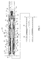
- FIG. 1 is a sectional view of a valve assembly in a run-in position according to one embodiment.
- FIG. 2 is a sectional view of the valve assembly in an open position according to one embodiment.
- FIG. 3 is a sectional view of the valve assembly in a reverse circulation position prior to actuation of a locking device according to one embodiment.
- FIG. 4 is a sectional view of the valve assembly in a reverse circulation position after actuation of the locking device according to one embodiment.
- FIG. 5 is a sectional view of the valve assembly after actuation of the locking device and prior to actuation of the valve assembly into a final closed position according to one embodiment.
- FIG. 6 is a sectional view of the valve assembly in a final closed position according to one embodiment.
- Embodiments of the invention relate to a reverse flow or cementing valve assembly 100 for use in a (open hole or cased) wellbore.
- the valve assembly 100 may be disposed on a work string below one or more fracturing sleeves and/or packers operable to conduct a fracturing operation in a wellbore.
- One or more float valves (such as one-way check valves) may also be coupled to the work string below the valve assembly 100 for allowing fluid flow out of the work string and into the wellbore, while preventing fluid flow from the wellbore back into the work string.
- the work string may be run into the wellbore while circulating fluid forward through the work sting and into the wellbore, which is generally done to displace any drilling or other wellbore fluids with a desired fluid, such as a conditioning fluid or a fracturing fluid. This forward circulation and displacement of wellbore fluids is also known as conditioning the well.
- the work string and valve assembly 100 may be run-in and positioned at the desired location within the wellbore, and then fluid may be circulated therethrough to condition the well.
- the valve assembly 100 may be positioned and operable in a vertical, lateral, or horizontal section of the wellbore.
- FIG. 1 illustrates a sectional view of the valve assembly 100 in a run-in position, e.g. when lowered on the work string into the wellbore.
- the valve assembly 100 includes an upper sub 10 , an outer housing 20 , and a lower sub 30 .
- the upper sub 10 may be coupled to the work string, which may comprise a coiled or threaded tubing string.
- the outer housing 20 may be coupled at one end to the upper sub 10 , and at an opposite end to the lower sub 30 , via a threaded/sealed connection.
- One or more ports 21 are disposed through the outer housing 20 for providing fluid communication between the interior and the exterior of the housing 20 , and particularly for providing fluid communication between the inner bore of the valve assembly 100 (and thus the work string) and the surrounding annulus as further described below.
- the outer housing 20 may support a locking device 40 , a closing device 50 , an opening device 60 , and a hydraulic lock compensation assembly 70 .
- the locking device 40 is operable to prevent the valve assembly 100 from being actuated prematurely into the final closed position illustrated in FIG. 6 .
- the closing device 50 is operable to actuate the valve assembly 100 into the final closed position.
- the opening device 60 is operable to actuate the valve assembly 100 into an open position, illustrated in FIG. 2 , to permit reverse circulation through the valve assembly 100 , illustrated in FIGS. 3 and 4 , to conducting a reverse flow (e.g. cementing) operation as further described below.
- a reverse flow e.g. cementing
- fluid may be supplied through the valve assembly 100 in a forward flowing direction and out into the wellbore.
- fluid may flow through the upper sub 10 and a flapper valve 47 of the locking device 40 .
- Fluid may then flow through an opening sleeve member 63 bore and one or more ports 68 of a lower housing 67 of the opening device 60 , and out through the lower sub 30 .
- the locking device 40 may further include an inner sleeve member 44 for supporting the flapper valve 47 , and an upper housing 41 for supporting the sleeve member 44 .
- the sleeve member 44 may be biased by a biasing member 45 (such as a spring), which is disposed between the sleeve member 44 and a retaining member 46 coupled to the lower end of the upper housing 41 .
- One or more dog (fixing) members 42 are movably disposed through the upper end of the upper housing 41 , and temporarily secure the sleeve member 44 in the upper housing 41 .
- a compressible ring member 43 (or other similar type of detent mechanism) may be coupled to the upper housing 41 and extends into a recess 81 of the outer housing 20 . The ring member 43 resists movement between the upper housing 41 and the outer housing 20 .
- the flapper valve 47 may be a tri-flapper valve assembly, and may permit fluid flow in one direction while preventing or substantially restricting fluid flow in the opposite direction.
- the flapper valve 47 may be biased into a closed position by a spring or other similar biasing member. Pressurized fluid flow in one direction may overcome the bias of the spring to open and permit fluid flow through the flapper valve 47 as illustrated in FIG. 1 . Pressurized fluid flow in the opposite direction acts with the bias of the spring to maintain the flapper valve 47 in a closed position to prevent or substantially restrict fluid flow in the opposite direction as illustrated in FIG. 3 .
- Other flapper valves, check valves, and/or one-way valves known in the art may be used with the embodiments described herein.
- the closing device 50 may also include another flapper valve 51 , and a flapper valve seat 52 coupled to a closing sleeve member 55 by a retaining member 53 .
- the flapper valve 51 is held in an open position by the upper housing 41 of the locking device 40 .
- One or more dog (fixing) members 54 are movably disposed through an upper end of the closing sleeve member 55 , and extend into a recess 83 in the outer housing 20 to temporarily secure the closing sleeve member 55 to the outer housing 20 .
- the dog members 54 are temporarily secured in the recess 83 by the upper housing 41 and/or the retaining member 46 of the locking device 40 .
- One or more seals 56 A, 56 B, 56 C are coupled to the closing sleeve member 55 and sealingly engage the outer housing 20 .
- the closing sleeve member 55 includes one or more ports 58 that are aligned with and/or are in fluid communication with the ports 21 of the outer housing when the valve assembly 100 is in the run-in position.
- a retaining member 57 may be threadedly coupled to the lower end of the closing sleeve member 55 .
- the retaining member 57 may also be releasably coupled to a ratchet member 64 by one or more releasable members 69 , such as shear screws.
- a ratchet ring 59 may be disposed between the retaining member 57 and the ratchet member 64 .
- the ratchet ring 59 engages teeth formed on the inner surface of the retaining member 57 and teeth formed on the outer surface of the ratchet member 64 to permit relative movement between the retaining and ratchet members in one direction, while preventing movement in the opposite direction.
- the retaining member 57 and thus the closing sleeve member 55 are moveable in a downward direction to close fluid communication through the ports 21 of the outer housing 20 .
- the opening device 60 may further include one or more seals 62 A, 62 B, such as o-rings, coupled to the opening sleeve member 63 that sealingly engage the closing sleeve member 55 .
- the ratchet member 64 may be releasably coupled to the opening sleeve member 63 by one or more releasable members 66 , such as shear screws.
- a ratchet ring 65 may be disposed between the opening sleeve member 63 and the ratchet member 64 .
- the ratchet ring 65 engages teeth formed on the outer surface of the opening sleeve member 63 and teeth formed on the inner surface of the ratchet member 64 to permit relative movement between the sleeve and ratchet members in one direction, while preventing movement in the opposite direction.
- the opening sleeve member 63 is moveable in a downward direction to open fluid communication through the ports 21 of the outer housing 20 and the ports 58 of the closing sleeve member 55 .
- the ratchet member 64 may be supported at a lower end by the lower housing 67 , which may be threadedly coupled to the lower sub 30 .
- the hydraulic lock compensation assembly 70 may include a mandrel 71 threadedly coupled to the lower housing 67 , and a plug member 72 and a biasing member 73 (such as a spring) secured in the mandrel 71 by a retaining member 74 .
- the biasing member 73 biases the plug member 72 against an inner shoulder of the mandrel 71 , which includes a bore in fluid communication with outer housing 20 .
- the plug member 72 is sealingly disposed in the mandrel 71 and prevents fluid flow through the mandrel 71 .
- the hydraulic lock compensation assembly 70 may be provided to compensate for any hydraulic lock that may occur within the valve assembly 100 , such as when actuated into the final closed position and the opening sleeve member 63 is moved downward and sealingly engages one or more seals 75 (such as o-rings) coupled to the mandrel 71 as illustrated in FIG. 6 .
- the locked hydraulic volume moves downward and forces the plug member 72 against the bias of the biasing member 73 to compensate for any potential hydraulic lock conditions/forces within the valve assembly 100 which may prevent movement of the closing sleeve member 55 as further illustrated in FIG. 6 .
- the lower housing 67 may also include one or more ports 76 for allowing fluid flow out of the outer housing 21 to prevent fluid locking of the opening and/or closing sleeve members 63 , 55 .
- FIG. 2 illustrates the valve assembly 100 in an open position.
- a closure member 80 such as a ball, dart, or other similar closure or plug-type member, may be dropped from surface through the work string.
- the closure member 80 may flow through the flapper valve 47 and land on a seat portion of the opening sleeve member 63 to close fluid flow through the bore of the opening sleeve member 63 .
- the seat portion of the opening sleeve member 63 may be tapered so that the closure member 80 can be wedged and secured in the sleeve member by the pressurized fluid to prevent inadvertent removal of the closure member 80 , such as when the valve assembly 100 is positioned horizontally and/or when reverse circulating through the valve assembly 100 .
- Pressurized fluid above the closure member 80 may also be used to force and release the releasable member 66 to move the opening sleeve member 63 in a downward direction.
- the ratchet ring 65 moves along the teeth disposed on the inner surface of the ratchet member 64 and prevents the opening sleeve member 63 from moving back in the opposite or upward direction.
- the opening sleeve member 63 may be moved until it engages a shoulder of the retaining member 57 .
- the one or more seals 62 A, 62 B and the opening sleeve member 63 are moved to open fluid communication through the ports 58 of the closing sleeve member 55 and the ports 21 of the outer housing 20 , thereby opening fluid communication to the annulus surrounding the valve assembly 100 .
- FIG. 3 illustrates the wellbore fluid flowing into the valve assembly 100 and acting against the flapper valve 47 .
- the pressurized fluid may apply a force sufficient to overcome the resistance of the ring member 43 , which resists movement of the upper housing 41 , the sleeve member 44 , and the flapper valve 47 relative to the outer housing 20 .
- the pressurized fluid may force the ring member 43 out of the recess 81 formed in the outer housing 20 , and move the upper housing 41 in an upward direction until the dog members 42 and/or the ring member 43 move radially outward into another recess 82 formed in the outer housing 20 .
- the upper housing 41 temporarily seals or substantially restricts fluid flow through one or more ports 48 of the sleeve member 44 when secured in the upper housing 41 .
- the dog members 42 are moved from securing the sleeve member 44 within the upper housing 41 , such that the biasing member 45 may then move the sleeve member 44 upward relative to the upper housing 41 to open fluid flow through one or more ports 48 of the sleeve member 44 as illustrated in FIG. 4 .
- the ports 48 permit fluid flow around the flapper valve 47 in the opposite direction when moved to a position outside of the upper housing 41 .
- the flapper valve 51 is released and may close against the flapper valve seat 52 (as illustrated in FIG. 5 ). Reverse fluid flow will lift or open the flapper valve 51 for fluid communication up through the work string as further illustrated in FIG. 4 .
- the dog members 54 are also released from engagement with the upper housing 41 and/or the retaining member 46 , to enable movement of the closing sleeve member 55 as further described below.
- the locking device 40 may comprise a rotary-vane releasing disc or member, through which forward fluid flow serves to lock the closing sleeve member 55 , but with reverse fluid flow the vanes will allow the disc or member to spin/rotate, thereby releasing the closing sleeve member 55 .
- a reverse flow operation such as a reverse cementing operation
- a fluid such as cement
- a fluid may be pumped down the annulus to force wellbore fluids into the valve assembly 100 for recovery back to the surface through the work string.
- the reverse flow may be monitored at the surface to verify that reverse circulation has been achieved.
- a wellbore conditioning fluid may be continuously pumped down the annulus and monitored at the surface until it returns up through the work string to confirm reverse circulation has been achieved through the valve assembly 100 .
- a predetermined amount of cement may be pumped into the annulus, which circulates the wellbore fluids back to the surface through the valve assembly 100 and work string.
- the cement may be used to seal the portion of the wellbore annulus above any packers or fracturing sleeves that are coupled to the work string.
- the amount of cement pumped into the wellbore annulus may be limited so that the cement remains above the wellbore fluids and does not reach the down-hole location of the valve assembly 100 to thereby prevent cement flow through the valve assembly 100 and/or the work string.
- a (liner-top) packer may be set, such as by pressurizing the work string after the valve assembly 100 is moved to the final closed position, to maintain the cement in a desired section of the wellbore.
- the cement may be maintained in a section of the wellbore above the valve assembly 100 and/or any other work string tools, such as other packers and sleeves, needed for conducting subsequent wellbore operations.
- FIG. 5 illustrates the valve assembly 100 after actuation of the locking device 40 and prior to moving the valve assembly 100 to the final closed position.
- the flapper valve 51 When reverse circulation or flow through the valve assembly 100 is stopped, the flapper valve 51 is biased into a closed position by a spring or other biasing member against the flapper valve seat 52 .
- the flapper valve 51 may seal or substantially restrict fluid flow through the closing sleeve member 55 from above.
- the work string and the valve assembly 100 above the flapper valve 51 may be pressurized to actuate the valve assembly 100 into the final closed position.
- FIG. 6 illustrates the valve assembly 100 in a final closed position.
- the valve assembly 100 may be actuated into the final closed position to close fluid communication with the wellbore annulus.
- Pressurized fluid may be forward circulated/pumped through the work string to the valve assembly 100 .
- the fluid may flow through the flapper valve 47 and/or the ports 48 of the sleeve member 44 to the flapper valve 51 .
- the components of the locking device 40 may be secured to the outer housing 20 by the ring member 43 and/or the dog members 42 engaging the recess 82 when actuating the valve assembly 100 to the final closed position.
- the pressurized fluid may act on the flapper valve 51 , which prevents or substantially restricts forward fluid flow through the valve assembly 100 .
- the fluid pressure may apply a force to the closing sleeve member 55 sufficient to move the dog members 54 out of the recess 83 of the outer housing 20 , and release the releasable members 69 to thereby move the closing sleeve member 55 to a position where the seals 56 A, 56 B seal off fluid communication to the ports 21 in the outer housing 20 .
- the closing sleeve member 55 is moved downward, the ratchet ring 59 moves along the teeth disposed on the outer surface of the ratchet member 64 and prevents the closing sleeve member 55 from moving back in the opposite or upward direction.
- the closing sleeve member 55 closes fluid communication between the valve assembly 100 and the wellbore, and specifically prevents fluids in the wellbore from flowing into the valve assembly 100 .
- the inner bore of the work string may be pressurized to actuate one or more other tools coupled to the work string above the valve assembly 100 , the other tools including but not limited to packers, fracture sleeves, and/or other valves.
- the work string may be pressurized to actuate one or more (open hole) packers into engagement with the wellbore to conduct a fracturing operation, and/or one or more (liner-top) packers to maintain the cement within a desired section of the wellbore.
- the pressurized fluid may also actuate a sleeve or valve to open communication through the work string adjacent an area of interest for conducting the fracturing operation.
- a fracturing fluid may be supplied through the work string and into the area of interest to conduct the fracturing operation.
- the fracturing fluid may be prevented from flowing up or down the annulus by the surrounding packers.
- one or more of the valve assembly 100 components may be formed from a drillable material, such that the assembly may be drilled out of the wellbore if desired.
- the work string and the valve assembly 100 enable forward circulation through the valve assembly 100 and one or more float (check) valves disposed below, and out the end of the work string when running the assembly into the well.
- fluid flow through the valve assembly 100 may be prevented or substantially restricted by dropping the closure member 80 onto the seat of the opening sleeve member 63 to open fluid communication through the ports 21 , 58 of the valve assembly 100 .
- Reverse circulation from the annulus through the ports 21 , 58 allows cementing of a desired section of the wellbore above the valve assembly 100 , and actuates the locking device 40 to release the flapper valve 51 and enable closing of the valve assembly 100 .
- the flapper valve 51 prevents or substantially restricts fluid flow through the valve assembly 100 , so that the work string above can be pressurized to move the valve assembly 100 to the final closed position and to actuate one or more other tools coupled to the work string.
- Advantages of the embodiments described herein include enabling a cementing operation to be conducted with standard (MZOH) packers and ball actuated fracturing sleeves; and no drill-out operations required between cementing and fracturing, resulting in improved operational efficiencies and cost savings.
- Other advantages include maintaining the integrity of the work string above all packers and fracturing sleeves, rather than being compromised by a port collar or other similar device which can create a leak path in the work string above the packers; and not requiring cementing of the entire wellbore length, including any horizontal or lateral portions of the wellbore.
Abstract
Description
Claims (27)
Priority Applications (3)
| Application Number | Priority Date | Filing Date | Title |
|---|---|---|---|
| US13/439,207 US9334700B2 (en) | 2012-04-04 | 2012-04-04 | Reverse cementing valve |
| CA2932093A CA2932093C (en) | 2012-04-04 | 2012-04-25 | Reverse cementing valve |
| CA2775330A CA2775330C (en) | 2012-04-04 | 2012-04-25 | Reverse cementing valve |
Applications Claiming Priority (1)
| Application Number | Priority Date | Filing Date | Title |
|---|---|---|---|
| US13/439,207 US9334700B2 (en) | 2012-04-04 | 2012-04-04 | Reverse cementing valve |
Publications (2)
| Publication Number | Publication Date |
|---|---|
| US20130264068A1 US20130264068A1 (en) | 2013-10-10 |
| US9334700B2 true US9334700B2 (en) | 2016-05-10 |
Family
ID=49289842
Family Applications (1)
| Application Number | Title | Priority Date | Filing Date |
|---|---|---|---|
| US13/439,207 Active 2034-10-04 US9334700B2 (en) | 2012-04-04 | 2012-04-04 | Reverse cementing valve |
Country Status (2)
| Country | Link |
|---|---|
| US (1) | US9334700B2 (en) |
| CA (2) | CA2932093C (en) |
Cited By (2)
| Publication number | Priority date | Publication date | Assignee | Title |
|---|---|---|---|---|
| US20190330941A1 (en) * | 2016-01-29 | 2019-10-31 | Saudi Arabian Oil Company | Reverse circulation well tool |
| US10954749B2 (en) | 2013-06-26 | 2021-03-23 | Weatherford Technology Holdings, Llc | Bidirectional downhole isolation valve |
Families Citing this family (14)
| Publication number | Priority date | Publication date | Assignee | Title |
|---|---|---|---|---|
| CA2855054C (en) * | 2012-09-24 | 2016-11-22 | Robert Grainger | Non-rotating wellbore tool and sealing method therefor |
| US10087725B2 (en) | 2013-04-11 | 2018-10-02 | Weatherford Technology Holdings, Llc | Telemetry operated tools for cementing a liner string |
| US9926769B2 (en) | 2013-11-07 | 2018-03-27 | Baker Hughes, A Ge Company, Llc | Systems and methods for downhole communication |
| US9605510B2 (en) * | 2014-06-25 | 2017-03-28 | Robert Grainger | Non-rotating connector for wellbore cementing tool |
| WO2016014253A1 (en) * | 2014-07-24 | 2016-01-28 | Weatherford/Lamb, Inc. | Reverse cementation of liner string for formation stimulation |
| US9683424B2 (en) * | 2015-02-06 | 2017-06-20 | Comitt Well Solutions Us Holding Inc. | Apparatus for injecting a fluid into a geological formation |
| US10267118B2 (en) * | 2015-02-23 | 2019-04-23 | Comitt Well Solutions LLC | Apparatus for injecting a fluid into a geological formation |
| US9995105B2 (en) * | 2015-05-15 | 2018-06-12 | Baker Hughes, A Ge Company, Llc | Method of placing cement sealing rings at predetermined annular locations around a tubular string |
| US10392898B2 (en) | 2016-06-16 | 2019-08-27 | Weatherford Technology Holdings, Llc | Mechanically operated reverse cementing crossover tool |
| CN106593345B (en) * | 2016-11-16 | 2019-05-28 | 中国海洋石油集团有限公司 | A kind of packer is anti-to solve seal structure in advance |
| WO2020096568A1 (en) | 2018-11-06 | 2020-05-14 | Halliburton Energy Services, Inc. | Apparatus, systems, and methods for dampening a wellbore pressure pulse during reverse circulation cementing |
| US11578557B2 (en) | 2020-08-19 | 2023-02-14 | Saudi Arabian Oil Company | Reverse stage cementing sub |
| CN114382437A (en) * | 2020-10-21 | 2022-04-22 | 中国石油天然气集团有限公司 | Backflow preventer |
| US11519258B2 (en) * | 2020-10-27 | 2022-12-06 | Halliburton Energy Services, Inc. | Pressure testing casing string during reverse cementing operations |
Citations (44)
| Publication number | Priority date | Publication date | Assignee | Title |
|---|---|---|---|---|
| US2675082A (en) | 1951-12-28 | 1954-04-13 | John A Hall | Method for cementing oil and gas wells |
| US3273650A (en) * | 1966-09-20 | Automatic fill-up and cementing devices for well pipes | ||
| US4044829A (en) * | 1975-01-13 | 1977-08-30 | Halliburton Company | Method and apparatus for annulus pressure responsive circulation and tester valve manipulation |
| US4391329A (en) | 1981-05-14 | 1983-07-05 | Union Oil Company Of California | Use of marker fluid in cementing offshore wells |
| US4452638A (en) | 1981-05-14 | 1984-06-05 | Union Oil Company Of California | Marker fluid composition for spotting cement in offshore wells |
| US4674573A (en) | 1985-09-09 | 1987-06-23 | Bode Robert E | Method and apparatus for placing cement plugs in wells |
| US4949788A (en) | 1989-11-08 | 1990-08-21 | Halliburton Company | Well completions using casing valves |
| US5494107A (en) | 1993-12-07 | 1996-02-27 | Bode; Robert E. | Reverse cementing system and method |
| US5890538A (en) | 1997-04-14 | 1999-04-06 | Amoco Corporation | Reverse circulation float equipment tool and process |
| US6244342B1 (en) | 1999-09-01 | 2001-06-12 | Halliburton Energy Services, Inc. | Reverse-cementing method and apparatus |
| US20030029611A1 (en) | 2001-08-10 | 2003-02-13 | Owens Steven C. | System and method for actuating a subterranean valve to terminate a reverse cementing operation |
| US6802374B2 (en) | 2002-10-30 | 2004-10-12 | Schlumberger Technology Corporation | Reverse cementing float shoe |
| US6802373B2 (en) | 2002-04-10 | 2004-10-12 | Bj Services Company | Apparatus and method of detecting interfaces between well fluids |
| US6920929B2 (en) | 2003-03-12 | 2005-07-26 | Halliburton Energy Services, Inc. | Reverse circulation cementing system and method |
| US7013971B2 (en) | 2003-05-21 | 2006-03-21 | Halliburton Energy Services, Inc. | Reverse circulation cementing process |
| US20060219407A1 (en) | 2005-03-14 | 2006-10-05 | Presssol Ltd. | Method and apparatus for cementing a well using concentric tubing or drill pipe |
| US7204304B2 (en) | 2004-02-25 | 2007-04-17 | Halliburton Energy Services, Inc. | Removable surface pack-off device for reverse cementing applications |
| US20070095533A1 (en) | 2005-11-01 | 2007-05-03 | Halliburton Energy Services, Inc. | Reverse cementing float equipment |
| US7225871B2 (en) | 2004-07-22 | 2007-06-05 | Halliburton Energy Services, Inc. | Apparatus and method for reverse circulation cementing a casing in an open-hole wellbore |
| US7252152B2 (en) | 2003-06-18 | 2007-08-07 | Weatherford/Lamb, Inc. | Methods and apparatus for actuating a downhole tool |
| US7252147B2 (en) | 2004-07-22 | 2007-08-07 | Halliburton Energy Services, Inc. | Cementing methods and systems for initiating fluid flow with reduced pumping pressure |
| US7270183B2 (en) | 2004-11-16 | 2007-09-18 | Halliburton Energy Services, Inc. | Cementing methods using compressible cement compositions |
| US7281584B2 (en) * | 2001-07-05 | 2007-10-16 | Smith International, Inc. | Multi-cycle downhill apparatus |
| US7284608B2 (en) | 2004-10-26 | 2007-10-23 | Halliburton Energy Services, Inc. | Casing strings and methods of using such strings in subterranean cementing operations |
| US7290612B2 (en) | 2004-12-16 | 2007-11-06 | Halliburton Energy Services, Inc. | Apparatus and method for reverse circulation cementing a casing in an open-hole wellbore |
| US7290611B2 (en) | 2004-07-22 | 2007-11-06 | Halliburton Energy Services, Inc. | Methods and systems for cementing wells that lack surface casing |
| US7293609B2 (en) | 2004-10-20 | 2007-11-13 | Halliburton Energy Services, Inc. | Treatment fluids comprising vitrified shale and methods of using such fluids in subterranean formations |
| US7303014B2 (en) | 2004-10-26 | 2007-12-04 | Halliburton Energy Services, Inc. | Casing strings and methods of using such strings in subterranean cementing operations |
| US7303008B2 (en) | 2004-10-26 | 2007-12-04 | Halliburton Energy Services, Inc. | Methods and systems for reverse-circulation cementing in subterranean formations |
| US7322412B2 (en) | 2004-08-30 | 2008-01-29 | Halliburton Energy Services, Inc. | Casing shoes and methods of reverse-circulation cementing of casing |
| US7357181B2 (en) | 2005-09-20 | 2008-04-15 | Halliburton Energy Services, Inc. | Apparatus for autofill deactivation of float equipment and method of reverse cementing |
| US20080135248A1 (en) | 2006-12-11 | 2008-06-12 | Halliburton Energy Service, Inc. | Method and apparatus for completing and fluid treating a wellbore |
| US7392840B2 (en) | 2005-12-20 | 2008-07-01 | Halliburton Energy Services, Inc. | Method and means to seal the casing-by-casing annulus at the surface for reverse circulation cement jobs |
| US20080196889A1 (en) | 2007-02-15 | 2008-08-21 | Daniel Bour | Reverse Circulation Cementing Valve |
| US7527104B2 (en) | 2006-02-07 | 2009-05-05 | Halliburton Energy Services, Inc. | Selectively activated float equipment |
| US7533728B2 (en) | 2007-01-04 | 2009-05-19 | Halliburton Energy Services, Inc. | Ball operated back pressure valve |
| US7540325B2 (en) | 2005-03-14 | 2009-06-02 | Presssol Ltd. | Well cementing apparatus and method |
| US7597146B2 (en) | 2006-10-06 | 2009-10-06 | Halliburton Energy Services, Inc. | Methods and apparatus for completion of well bores |
| US20090260816A1 (en) | 2008-04-21 | 2009-10-22 | Earl Webb | Method and System for Cementing |
| US7614451B2 (en) | 2007-02-16 | 2009-11-10 | Halliburton Energy Services, Inc. | Method for constructing and treating subterranean formations |
| US7654324B2 (en) | 2007-07-16 | 2010-02-02 | Halliburton Energy Services, Inc. | Reverse-circulation cementing of surface casing |
| US7712527B2 (en) | 2007-04-02 | 2010-05-11 | Halliburton Energy Services, Inc. | Use of micro-electro-mechanical systems (MEMS) in well treatments |
| US8104505B2 (en) | 2009-05-22 | 2012-01-31 | Baker Hughes Incorporated | Two-way actuator and method |
| US20120322698A1 (en) | 2004-10-20 | 2012-12-20 | Dealy Sears T | Treatment fluids comprising pumicite and methods of using such fluids in subterranean formations |
-
2012
- 2012-04-04 US US13/439,207 patent/US9334700B2/en active Active
- 2012-04-25 CA CA2932093A patent/CA2932093C/en active Active
- 2012-04-25 CA CA2775330A patent/CA2775330C/en active Active
Patent Citations (58)
| Publication number | Priority date | Publication date | Assignee | Title |
|---|---|---|---|---|
| US3273650A (en) * | 1966-09-20 | Automatic fill-up and cementing devices for well pipes | ||
| US2675082A (en) | 1951-12-28 | 1954-04-13 | John A Hall | Method for cementing oil and gas wells |
| US4044829A (en) * | 1975-01-13 | 1977-08-30 | Halliburton Company | Method and apparatus for annulus pressure responsive circulation and tester valve manipulation |
| US4391329A (en) | 1981-05-14 | 1983-07-05 | Union Oil Company Of California | Use of marker fluid in cementing offshore wells |
| US4452638A (en) | 1981-05-14 | 1984-06-05 | Union Oil Company Of California | Marker fluid composition for spotting cement in offshore wells |
| US4674573A (en) | 1985-09-09 | 1987-06-23 | Bode Robert E | Method and apparatus for placing cement plugs in wells |
| US4949788A (en) | 1989-11-08 | 1990-08-21 | Halliburton Company | Well completions using casing valves |
| US5494107A (en) | 1993-12-07 | 1996-02-27 | Bode; Robert E. | Reverse cementing system and method |
| US5890538A (en) | 1997-04-14 | 1999-04-06 | Amoco Corporation | Reverse circulation float equipment tool and process |
| US6244342B1 (en) | 1999-09-01 | 2001-06-12 | Halliburton Energy Services, Inc. | Reverse-cementing method and apparatus |
| US7281584B2 (en) * | 2001-07-05 | 2007-10-16 | Smith International, Inc. | Multi-cycle downhill apparatus |
| US20030029611A1 (en) | 2001-08-10 | 2003-02-13 | Owens Steven C. | System and method for actuating a subterranean valve to terminate a reverse cementing operation |
| US6802373B2 (en) | 2002-04-10 | 2004-10-12 | Bj Services Company | Apparatus and method of detecting interfaces between well fluids |
| US7066256B2 (en) | 2002-04-10 | 2006-06-27 | Bj Services Company | Apparatus and method of detecting interfaces between well fluids |
| US6802374B2 (en) | 2002-10-30 | 2004-10-12 | Schlumberger Technology Corporation | Reverse cementing float shoe |
| US6920929B2 (en) | 2003-03-12 | 2005-07-26 | Halliburton Energy Services, Inc. | Reverse circulation cementing system and method |
| US7013971B2 (en) | 2003-05-21 | 2006-03-21 | Halliburton Energy Services, Inc. | Reverse circulation cementing process |
| US7252152B2 (en) | 2003-06-18 | 2007-08-07 | Weatherford/Lamb, Inc. | Methods and apparatus for actuating a downhole tool |
| US7204304B2 (en) | 2004-02-25 | 2007-04-17 | Halliburton Energy Services, Inc. | Removable surface pack-off device for reverse cementing applications |
| US7290611B2 (en) | 2004-07-22 | 2007-11-06 | Halliburton Energy Services, Inc. | Methods and systems for cementing wells that lack surface casing |
| US7225871B2 (en) | 2004-07-22 | 2007-06-05 | Halliburton Energy Services, Inc. | Apparatus and method for reverse circulation cementing a casing in an open-hole wellbore |
| US7252147B2 (en) | 2004-07-22 | 2007-08-07 | Halliburton Energy Services, Inc. | Cementing methods and systems for initiating fluid flow with reduced pumping pressure |
| US7621337B2 (en) | 2004-08-30 | 2009-11-24 | Halliburton Energy Services, Inc. | Casing shoes and methods of reverse-circulation cementing of casing |
| US7621336B2 (en) | 2004-08-30 | 2009-11-24 | Halliburton Energy Services, Inc. | Casing shoes and methods of reverse-circulation cementing of casing |
| US7503399B2 (en) | 2004-08-30 | 2009-03-17 | Halliburton Energy Services, Inc. | Casing shoes and methods of reverse-circulation cementing of casing |
| US7938186B1 (en) | 2004-08-30 | 2011-05-10 | Halliburton Energy Services Inc. | Casing shoes and methods of reverse-circulation cementing of casing |
| US7322412B2 (en) | 2004-08-30 | 2008-01-29 | Halliburton Energy Services, Inc. | Casing shoes and methods of reverse-circulation cementing of casing |
| US20080060814A1 (en) | 2004-08-30 | 2008-03-13 | Badalamenti Anthony M | Casing Shoes and Methods of Reverse-Circulation Cementing of Casing |
| US20120322698A1 (en) | 2004-10-20 | 2012-12-20 | Dealy Sears T | Treatment fluids comprising pumicite and methods of using such fluids in subterranean formations |
| US7293609B2 (en) | 2004-10-20 | 2007-11-13 | Halliburton Energy Services, Inc. | Treatment fluids comprising vitrified shale and methods of using such fluids in subterranean formations |
| US7303014B2 (en) | 2004-10-26 | 2007-12-04 | Halliburton Energy Services, Inc. | Casing strings and methods of using such strings in subterranean cementing operations |
| US7409991B2 (en) | 2004-10-26 | 2008-08-12 | Halliburton Energy Services, Inc. | Methods of using casing strings in subterranean cementing operations |
| US7303008B2 (en) | 2004-10-26 | 2007-12-04 | Halliburton Energy Services, Inc. | Methods and systems for reverse-circulation cementing in subterranean formations |
| US20080011482A1 (en) | 2004-10-26 | 2008-01-17 | Halliburton Energy Services | Systems for Reverse-Circulation Cementing in Subterranean Formations |
| US7451817B2 (en) | 2004-10-26 | 2008-11-18 | Halliburton Energy Services, Inc. | Methods of using casing strings in subterranean cementing operations |
| US7389815B2 (en) | 2004-10-26 | 2008-06-24 | Halliburton Energy Services, Inc. | Methods for reverse-circulation cementing in subterranean formations |
| US7284608B2 (en) | 2004-10-26 | 2007-10-23 | Halliburton Energy Services, Inc. | Casing strings and methods of using such strings in subterranean cementing operations |
| US7401646B2 (en) | 2004-10-26 | 2008-07-22 | Halliburton Energy Services Inc. | Methods for reverse-circulation cementing in subterranean formations |
| US7404440B2 (en) | 2004-10-26 | 2008-07-29 | Halliburton Energy Services, Inc. | Methods of using casing strings in subterranean cementing operations |
| US7270183B2 (en) | 2004-11-16 | 2007-09-18 | Halliburton Energy Services, Inc. | Cementing methods using compressible cement compositions |
| US7290612B2 (en) | 2004-12-16 | 2007-11-06 | Halliburton Energy Services, Inc. | Apparatus and method for reverse circulation cementing a casing in an open-hole wellbore |
| US20060219407A1 (en) | 2005-03-14 | 2006-10-05 | Presssol Ltd. | Method and apparatus for cementing a well using concentric tubing or drill pipe |
| US7540325B2 (en) | 2005-03-14 | 2009-06-02 | Presssol Ltd. | Well cementing apparatus and method |
| US7357181B2 (en) | 2005-09-20 | 2008-04-15 | Halliburton Energy Services, Inc. | Apparatus for autofill deactivation of float equipment and method of reverse cementing |
| US20070095533A1 (en) | 2005-11-01 | 2007-05-03 | Halliburton Energy Services, Inc. | Reverse cementing float equipment |
| US7533729B2 (en) | 2005-11-01 | 2009-05-19 | Halliburton Energy Services, Inc. | Reverse cementing float equipment |
| US7392840B2 (en) | 2005-12-20 | 2008-07-01 | Halliburton Energy Services, Inc. | Method and means to seal the casing-by-casing annulus at the surface for reverse circulation cement jobs |
| US7527104B2 (en) | 2006-02-07 | 2009-05-05 | Halliburton Energy Services, Inc. | Selectively activated float equipment |
| US7597146B2 (en) | 2006-10-06 | 2009-10-06 | Halliburton Energy Services, Inc. | Methods and apparatus for completion of well bores |
| US20080135248A1 (en) | 2006-12-11 | 2008-06-12 | Halliburton Energy Service, Inc. | Method and apparatus for completing and fluid treating a wellbore |
| US7533728B2 (en) | 2007-01-04 | 2009-05-19 | Halliburton Energy Services, Inc. | Ball operated back pressure valve |
| US20080196889A1 (en) | 2007-02-15 | 2008-08-21 | Daniel Bour | Reverse Circulation Cementing Valve |
| US7614451B2 (en) | 2007-02-16 | 2009-11-10 | Halliburton Energy Services, Inc. | Method for constructing and treating subterranean formations |
| US7712527B2 (en) | 2007-04-02 | 2010-05-11 | Halliburton Energy Services, Inc. | Use of micro-electro-mechanical systems (MEMS) in well treatments |
| US7654324B2 (en) | 2007-07-16 | 2010-02-02 | Halliburton Energy Services, Inc. | Reverse-circulation cementing of surface casing |
| US8162047B2 (en) | 2007-07-16 | 2012-04-24 | Halliburton Energy Services Inc. | Reverse-circulation cementing of surface casing |
| US20090260816A1 (en) | 2008-04-21 | 2009-10-22 | Earl Webb | Method and System for Cementing |
| US8104505B2 (en) | 2009-05-22 | 2012-01-31 | Baker Hughes Incorporated | Two-way actuator and method |
Non-Patent Citations (1)
| Title |
|---|
| Canadian Office Action dated Feb. 13, 2015, for Canadian Patent Application No. 2,775,330. |
Cited By (5)
| Publication number | Priority date | Publication date | Assignee | Title |
|---|---|---|---|---|
| US10954749B2 (en) | 2013-06-26 | 2021-03-23 | Weatherford Technology Holdings, Llc | Bidirectional downhole isolation valve |
| US20190330941A1 (en) * | 2016-01-29 | 2019-10-31 | Saudi Arabian Oil Company | Reverse circulation well tool |
| US20190330940A1 (en) * | 2016-01-29 | 2019-10-31 | Saudi Arabian Oil Company | Reverse circulation well tool |
| US10641052B2 (en) * | 2016-01-29 | 2020-05-05 | Saudi Arabian Oil Company | Reverse circulation well tool |
| US10704348B2 (en) * | 2016-01-29 | 2020-07-07 | Saudi Arabian Oil Company | Reverse circulation well tool |
Also Published As
| Publication number | Publication date |
|---|---|
| CA2775330A1 (en) | 2013-10-04 |
| CA2775330C (en) | 2016-08-16 |
| CA2932093A1 (en) | 2013-10-04 |
| US20130264068A1 (en) | 2013-10-10 |
| CA2932093C (en) | 2018-02-20 |
Similar Documents
| Publication | Publication Date | Title |
|---|---|---|
| US9334700B2 (en) | Reverse cementing valve | |
| CA2778311C (en) | Downhole progressive pressurization actuated tool and method of using the same | |
| EP2189622B1 (en) | Casing valves system for selective well stimulation and control | |
| US9976384B2 (en) | Toe sleeve isolation system for cemented casing in borehole | |
| US7857052B2 (en) | Stage cementing methods used in casing while drilling | |
| US20140076560A1 (en) | Wellbore cementing tool having one way flow | |
| US9909390B2 (en) | Stage tool with lower tubing isolation | |
| US9260930B2 (en) | Pressure testing valve and method of using the same | |
| US9856715B2 (en) | Stage tool for wellbore cementing | |
| EP3272996B1 (en) | Pressure testing valve and method of using the same | |
| US20120261136A1 (en) | Selectively activatable and deactivatable wellbore pressure isolation device | |
| WO2011137112A2 (en) | Downhole barrier device | |
| US20180179857A1 (en) | Stage tool | |
| EP2948623B1 (en) | Pressure testing valve and method of using the same | |
| US20190153811A1 (en) | Selective multi-stage cementing of casing | |
| US11946336B1 (en) | Isolating a section of a wellbore | |
| US9915124B2 (en) | Piston float equipment | |
| CA2821500A1 (en) | Casing valves system for selective well stimulation and control |
Legal Events
| Date | Code | Title | Description |
|---|---|---|---|
| AS | Assignment |
Owner name: WEATHERFORD/LAMB, INC., TEXAS Free format text: ASSIGNMENT OF ASSIGNORS INTEREST;ASSIGNORS:HANSON, ANDREW JAMES;MARCIN, JOZEPH ROBERT;BIEDERMANN, RANDAL BRENT;AND OTHERS;SIGNING DATES FROM 20120330 TO 20120403;REEL/FRAME:027988/0341 |
|
| AS | Assignment |
Owner name: WEATHERFORD/LAMB, INC., TEXAS Free format text: ASSIGNMENT OF ASSIGNORS INTEREST;ASSIGNOR:ANDERSEN, CLAYTON R.;REEL/FRAME:031623/0740 Effective date: 20131118 |
|
| AS | Assignment |
Owner name: WEATHERFORD TECHNOLOGY HOLDINGS, LLC, TEXAS Free format text: ASSIGNMENT OF ASSIGNORS INTEREST;ASSIGNOR:WEATHERFORD/LAMB, INC.;REEL/FRAME:034526/0272 Effective date: 20140901 |
|
| STCF | Information on status: patent grant |
Free format text: PATENTED CASE |
|
| MAFP | Maintenance fee payment |
Free format text: PAYMENT OF MAINTENANCE FEE, 4TH YEAR, LARGE ENTITY (ORIGINAL EVENT CODE: M1551); ENTITY STATUS OF PATENT OWNER: LARGE ENTITY Year of fee payment: 4 |
|
| AS | Assignment |
Owner name: WELLS FARGO BANK NATIONAL ASSOCIATION AS AGENT, TEXAS Free format text: SECURITY INTEREST;ASSIGNORS:WEATHERFORD TECHNOLOGY HOLDINGS LLC;WEATHERFORD NETHERLANDS B.V.;WEATHERFORD NORGE AS;AND OTHERS;REEL/FRAME:051891/0089 Effective date: 20191213 |
|
| AS | Assignment |
Owner name: DEUTSCHE BANK TRUST COMPANY AMERICAS, AS ADMINISTR Free format text: SECURITY INTEREST;ASSIGNORS:WEATHERFORD TECHNOLOGY HOLDINGS, LLC;WEATHERFORD NETHERLANDS B.V.;WEATHERFORD NORGE AS;AND OTHERS;REEL/FRAME:051419/0140 Effective date: 20191213 Owner name: DEUTSCHE BANK TRUST COMPANY AMERICAS, AS ADMINISTRATIVE AGENT, NEW YORK Free format text: SECURITY INTEREST;ASSIGNORS:WEATHERFORD TECHNOLOGY HOLDINGS, LLC;WEATHERFORD NETHERLANDS B.V.;WEATHERFORD NORGE AS;AND OTHERS;REEL/FRAME:051419/0140 Effective date: 20191213 |
|
| AS | Assignment |
Owner name: WEATHERFORD SWITZERLAND TRADING AND DEVELOPMENT GMBH, TEXAS Free format text: RELEASE BY SECURED PARTY;ASSIGNOR:WELLS FARGO BANK, NATIONAL ASSOCIATION;REEL/FRAME:053838/0323 Effective date: 20200828 Owner name: HIGH PRESSURE INTEGRITY, INC., TEXAS Free format text: RELEASE BY SECURED PARTY;ASSIGNOR:WELLS FARGO BANK, NATIONAL ASSOCIATION;REEL/FRAME:053838/0323 Effective date: 20200828 Owner name: WEATHERFORD CANADA LTD., TEXAS Free format text: RELEASE BY SECURED PARTY;ASSIGNOR:WELLS FARGO BANK, NATIONAL ASSOCIATION;REEL/FRAME:053838/0323 Effective date: 20200828 Owner name: PRECISION ENERGY SERVICES, INC., TEXAS Free format text: RELEASE BY SECURED PARTY;ASSIGNOR:WELLS FARGO BANK, NATIONAL ASSOCIATION;REEL/FRAME:053838/0323 Effective date: 20200828 Owner name: WEATHERFORD TECHNOLOGY HOLDINGS, LLC, TEXAS Free format text: RELEASE BY SECURED PARTY;ASSIGNOR:WELLS FARGO BANK, NATIONAL ASSOCIATION;REEL/FRAME:053838/0323 Effective date: 20200828 Owner name: WEATHERFORD NORGE AS, TEXAS Free format text: RELEASE BY SECURED PARTY;ASSIGNOR:WELLS FARGO BANK, NATIONAL ASSOCIATION;REEL/FRAME:053838/0323 Effective date: 20200828 Owner name: WEATHERFORD NETHERLANDS B.V., TEXAS Free format text: RELEASE BY SECURED PARTY;ASSIGNOR:WELLS FARGO BANK, NATIONAL ASSOCIATION;REEL/FRAME:053838/0323 Effective date: 20200828 Owner name: WEATHERFORD U.K. LIMITED, TEXAS Free format text: RELEASE BY SECURED PARTY;ASSIGNOR:WELLS FARGO BANK, NATIONAL ASSOCIATION;REEL/FRAME:053838/0323 Effective date: 20200828 Owner name: PRECISION ENERGY SERVICES ULC, TEXAS Free format text: RELEASE BY SECURED PARTY;ASSIGNOR:WELLS FARGO BANK, NATIONAL ASSOCIATION;REEL/FRAME:053838/0323 Effective date: 20200828 Owner name: WILMINGTON TRUST, NATIONAL ASSOCIATION, MINNESOTA Free format text: SECURITY INTEREST;ASSIGNORS:WEATHERFORD TECHNOLOGY HOLDINGS, LLC;WEATHERFORD NETHERLANDS B.V.;WEATHERFORD NORGE AS;AND OTHERS;REEL/FRAME:054288/0302 Effective date: 20200828 |
|
| AS | Assignment |
Owner name: WILMINGTON TRUST, NATIONAL ASSOCIATION, MINNESOTA Free format text: SECURITY INTEREST;ASSIGNORS:WEATHERFORD TECHNOLOGY HOLDINGS, LLC;WEATHERFORD NETHERLANDS B.V.;WEATHERFORD NORGE AS;AND OTHERS;REEL/FRAME:057683/0706 Effective date: 20210930 Owner name: WEATHERFORD U.K. LIMITED, TEXAS Free format text: RELEASE BY SECURED PARTY;ASSIGNOR:WILMINGTON TRUST, NATIONAL ASSOCIATION;REEL/FRAME:057683/0423 Effective date: 20210930 Owner name: PRECISION ENERGY SERVICES ULC, TEXAS Free format text: RELEASE BY SECURED PARTY;ASSIGNOR:WILMINGTON TRUST, NATIONAL ASSOCIATION;REEL/FRAME:057683/0423 Effective date: 20210930 Owner name: WEATHERFORD SWITZERLAND TRADING AND DEVELOPMENT GMBH, TEXAS Free format text: RELEASE BY SECURED PARTY;ASSIGNOR:WILMINGTON TRUST, NATIONAL ASSOCIATION;REEL/FRAME:057683/0423 Effective date: 20210930 Owner name: WEATHERFORD CANADA LTD, TEXAS Free format text: RELEASE BY SECURED PARTY;ASSIGNOR:WILMINGTON TRUST, NATIONAL ASSOCIATION;REEL/FRAME:057683/0423 Effective date: 20210930 Owner name: PRECISION ENERGY SERVICES, INC., TEXAS Free format text: RELEASE BY SECURED PARTY;ASSIGNOR:WILMINGTON TRUST, NATIONAL ASSOCIATION;REEL/FRAME:057683/0423 Effective date: 20210930 Owner name: HIGH PRESSURE INTEGRITY, INC., TEXAS Free format text: RELEASE BY SECURED PARTY;ASSIGNOR:WILMINGTON TRUST, NATIONAL ASSOCIATION;REEL/FRAME:057683/0423 Effective date: 20210930 Owner name: WEATHERFORD NORGE AS, TEXAS Free format text: RELEASE BY SECURED PARTY;ASSIGNOR:WILMINGTON TRUST, NATIONAL ASSOCIATION;REEL/FRAME:057683/0423 Effective date: 20210930 Owner name: WEATHERFORD NETHERLANDS B.V., TEXAS Free format text: RELEASE BY SECURED PARTY;ASSIGNOR:WILMINGTON TRUST, NATIONAL ASSOCIATION;REEL/FRAME:057683/0423 Effective date: 20210930 Owner name: WEATHERFORD TECHNOLOGY HOLDINGS, LLC, TEXAS Free format text: RELEASE BY SECURED PARTY;ASSIGNOR:WILMINGTON TRUST, NATIONAL ASSOCIATION;REEL/FRAME:057683/0423 Effective date: 20210930 |
|
| AS | Assignment |
Owner name: WELLS FARGO BANK, NATIONAL ASSOCIATION, NORTH CAROLINA Free format text: PATENT SECURITY INTEREST ASSIGNMENT AGREEMENT;ASSIGNOR:DEUTSCHE BANK TRUST COMPANY AMERICAS;REEL/FRAME:063470/0629 Effective date: 20230131 |
|
| MAFP | Maintenance fee payment |
Free format text: PAYMENT OF MAINTENANCE FEE, 8TH YEAR, LARGE ENTITY (ORIGINAL EVENT CODE: M1552); ENTITY STATUS OF PATENT OWNER: LARGE ENTITY Year of fee payment: 8 |