US9323010B2 - Structures formed using monocrystalline silicon and/or other materials for optical and other applications - Google Patents
Structures formed using monocrystalline silicon and/or other materials for optical and other applications Download PDFInfo
- Publication number
- US9323010B2 US9323010B2 US13/454,713 US201213454713A US9323010B2 US 9323010 B2 US9323010 B2 US 9323010B2 US 201213454713 A US201213454713 A US 201213454713A US 9323010 B2 US9323010 B2 US 9323010B2
- Authority
- US
- United States
- Prior art keywords
- layer
- cavity
- gaps
- forming
- substrate
- Prior art date
- Legal status (The legal status is an assumption and is not a legal conclusion. Google has not performed a legal analysis and makes no representation as to the accuracy of the status listed.)
- Active, expires
Links
Images


Classifications
-
- G—PHYSICS
- G02—OPTICS
- G02B—OPTICAL ELEMENTS, SYSTEMS OR APPARATUS
- G02B6/00—Light guides; Structural details of arrangements comprising light guides and other optical elements, e.g. couplings
- G02B6/24—Coupling light guides
- G02B6/42—Coupling light guides with opto-electronic elements
- G02B6/4201—Packages, e.g. shape, construction, internal or external details
- G02B6/4204—Packages, e.g. shape, construction, internal or external details the coupling comprising intermediate optical elements, e.g. lenses, holograms
- G02B6/4214—Packages, e.g. shape, construction, internal or external details the coupling comprising intermediate optical elements, e.g. lenses, holograms the intermediate optical element having redirecting reflective means, e.g. mirrors, prisms for deflecting the radiation from horizontal to down- or upward direction toward a device
-
- G—PHYSICS
- G02—OPTICS
- G02B—OPTICAL ELEMENTS, SYSTEMS OR APPARATUS
- G02B6/00—Light guides; Structural details of arrangements comprising light guides and other optical elements, e.g. couplings
- G02B6/24—Coupling light guides
- G02B6/36—Mechanical coupling means
- G02B6/3628—Mechanical coupling means for mounting fibres to supporting carriers
- G02B6/3684—Mechanical coupling means for mounting fibres to supporting carriers characterised by the manufacturing process of surface profiling of the supporting carrier
- G02B6/3692—Mechanical coupling means for mounting fibres to supporting carriers characterised by the manufacturing process of surface profiling of the supporting carrier with surface micromachining involving etching, e.g. wet or dry etching steps
-
- G—PHYSICS
- G02—OPTICS
- G02B—OPTICAL ELEMENTS, SYSTEMS OR APPARATUS
- G02B6/00—Light guides; Structural details of arrangements comprising light guides and other optical elements, e.g. couplings
- G02B6/24—Coupling light guides
- G02B6/36—Mechanical coupling means
- G02B6/3628—Mechanical coupling means for mounting fibres to supporting carriers
- G02B6/3632—Mechanical coupling means for mounting fibres to supporting carriers characterised by the cross-sectional shape of the mechanical coupling means
- G02B6/3636—Mechanical coupling means for mounting fibres to supporting carriers characterised by the cross-sectional shape of the mechanical coupling means the mechanical coupling means being grooves
-
- G—PHYSICS
- G02—OPTICS
- G02B—OPTICAL ELEMENTS, SYSTEMS OR APPARATUS
- G02B6/00—Light guides; Structural details of arrangements comprising light guides and other optical elements, e.g. couplings
- G02B6/24—Coupling light guides
- G02B6/36—Mechanical coupling means
- G02B6/3628—Mechanical coupling means for mounting fibres to supporting carriers
- G02B6/3648—Supporting carriers of a microbench type, i.e. with micromachined additional mechanical structures
- G02B6/3652—Supporting carriers of a microbench type, i.e. with micromachined additional mechanical structures the additional structures being prepositioning mounting areas, allowing only movement in one dimension, e.g. grooves, trenches or vias in the microbench surface, i.e. self aligning supporting carriers
-
- G—PHYSICS
- G02—OPTICS
- G02B—OPTICAL ELEMENTS, SYSTEMS OR APPARATUS
- G02B6/00—Light guides; Structural details of arrangements comprising light guides and other optical elements, e.g. couplings
- G02B6/24—Coupling light guides
- G02B6/42—Coupling light guides with opto-electronic elements
- G02B6/4201—Packages, e.g. shape, construction, internal or external details
- G02B6/4249—Packages, e.g. shape, construction, internal or external details comprising arrays of active devices and fibres
-
- Y—GENERAL TAGGING OF NEW TECHNOLOGICAL DEVELOPMENTS; GENERAL TAGGING OF CROSS-SECTIONAL TECHNOLOGIES SPANNING OVER SEVERAL SECTIONS OF THE IPC; TECHNICAL SUBJECTS COVERED BY FORMER USPC CROSS-REFERENCE ART COLLECTIONS [XRACs] AND DIGESTS
- Y10—TECHNICAL SUBJECTS COVERED BY FORMER USPC
- Y10T—TECHNICAL SUBJECTS COVERED BY FORMER US CLASSIFICATION
- Y10T29/00—Metal working
- Y10T29/49—Method of mechanical manufacture
- Y10T29/49002—Electrical device making
- Y10T29/49117—Conductor or circuit manufacturing
Definitions
- the present invention relates to structures that can be used for circuits that process optical signals and for other circuits.
- optical and light denote electromagnetic radiation of any spectrum, not limited to visible light; the terms “optical fiber” or just “fiber” denote an optical fiber cable.
- the present invention also relates to etching of monocrystalline silicon substrates to provide suitable angles that can be used for optical and non-optical purposes.
- Fiber optics is increasingly used to transmit information to and from electrical circuits. Energy conversion between optical fiber and electrical circuitry is performed by opto-electrical transducers. Miniature packages have been created which combine the transducers, the optical fiber, and electrical circuitry to achieve high speed and low power losses.
- One example is described in Hsu-Liang Hsiao et al., “Compact and passive-alignment 4-channel x 2.5-Gbps optical interconnect modules based on silicon optical benches with 45° micro-reflectors”, OPTICS EXPRESS, 21 Dec. 2009, Vol. 17, No. 26, pages 24250-24260, illustrated in FIGS. 1-3 .
- FIG. 1 shows optical fibers 104 ( 104 . 1 and 104 . 2 ) used to interconnect integrated circuits (chips) 110 . 1 , 110 . 2 mounted on respective printed circuit boards (PCBs) 114 . 1 , 114 . 2 .
- Chip 110 . 1 , fiber 104 . 1 , and PCB 114 . 1 are part of a signal transmitting module 116 . 1 .
- Chip 1101 . 2 , fiber 104 . 2 , and PCB 114 . 2 are part of a signal receiving module 116 . 2 .
- Electrical signals from chip 110 . 1 are provided to an opto-electronic transducer 120 . 1 for conversion to light. Transducer 120 .
- Transducer 120 . 1 is mounted on a silicon interposer (silicon optical bench, or SiOB) 124 . 1 made using a silicon substrate 130 . 1 .
- Conductive lines 134 . 1 transmit electrical signals from chip 110 . 1 to transducer 120 . 1 .
- the transducer produces optical signals in a vertical light beam 140 . 1 .
- Light beam 140 . 1 is reflected by a mirror 144 . 1 formed of a gold layer deposited on the silicon interposer's surface inclined at 45° to the horizontal. The reflected beam from mirror 144 . 1 enters the optical fiber 104 . 1 .
- Fiber 104 . 1 is connected to a fiber 104 . 2 of module 116 . 2 by a connector 150 .
- Module 116 . 2 is similar to module 116 . 1 .
- the optical signals are emitted from fiber 104 . 2 in a horizontal beam 140 . 2 , which is reflected by a 45° mirror 144 . 2 to travel vertically to a transducer 120 . 2 .
- the mirror is part of a silicon interposer 124 . 2 made using silicon substrate 130 . 2 .
- Transducer 120 . 2 is mounted on interposer 124 . 2 .
- Transducer 120 . 2 is a photodetector integrated circuit which converts the optical signals into electric signals provided, via conductive lines 134 . 2 , to chip 110 . 2 .
- Interposer 124 . 2 and chip 110 . 2 are mounted on PCB 114 . 2 .
- FIGS. 2 and 3 illustrate a module 116 which can be 116 . 1 or 116 . 2 .
- FIG. 2 is a top view, and FIG. 3 shows a cross section by a plane transversal to fibers 104 .
- Each module 116 . 1 , 116 . 2 has four fibers 104 (i.e. 104 . 1 or 104 . 2 );
- transducer 120 . 1 has four lasers emitting four respective beams 140 . 1 entering four respective fibers 104 . 1 ;
- transducer 120 . 2 has four photodetectors which receive four respective beams 140 . 2 passing through four respective fibers 104 . 2 .
- FIG. 1 illustrates a module 116 which can be 116 . 1 or 116 . 2 .
- FIG. 2 is a top view
- FIG. 3 shows a cross section by a plane transversal to fibers 104 .
- Each module 116 . 1 , 116 . 2 has
- monocrystalline silicon substrate 130 having (100)-orientation supports all the four fibers 104 .
- the fibers are mounted in V-grooves 310 formed by a wet etch of substrate 130 .
- the etch also forms the silicon surface underlying the mirror 144 .
- the V-grooves have 45°-sloped sidewalls. The 45° angle is produced by an anisotropic wet etch of silicon substrate 130 which is a monocrystalline silicon wafer of (100)-orientation.
- the sloped sidewalls are (110) crystal planes.
- the etchant is a solution of KOH (potassium hydroxide) and isopropyl alcohol (IPA) chosen to suppress the etching rate of ⁇ 110 ⁇ planes to a level below the etching rate of ⁇ 111 ⁇ planes.
- KOH potassium hydroxide
- IPA isopropyl alcohol
- Some embodiments of the present invention provide optical interposers and methods of their fabrication that allow precise fiber positioning in grooves of different shapes.
- rectangular grooves can be used (with vertical sidewalls).
- Vertical sidewalls may be desirable to reduce the pitch between the adjacent fibers (measured as the distance between the centers of the adjacent fibers or adjacent grooves).
- the width of each groove at the top is greater than each fiber's diameter. If the sidewalls are vertical, then the width of each groove can be equal to the fiber's diameter. A denser, more compact structure can therefore be provided for a given fiber diameter (i.e. the diameter-to-pitch ratio can be increased).
- the groove width, and the spacing between the grooves are independent of the grooves' depth (with V-grooves, the grooves' width at the top increases with depth, and the spacing between the grooves correspondingly decreases). If the groove width and the spacing between the grooves are independent of the grooves' depth, then the fibers' vertical position (defined by the depth) is independent of the spacing between the grooves. This is advantageous because the areas between the grooves can be used for various purposes (e.g. for circuitry or for mechanical support of cantilevered transducers), and the spacing between the grooves can be optimized independently from the fibers' vertical positions.
- the invention includes V-groove embodiments, and is not limited to vertical sidewalls or other features described herein except as defined by the claims.
- the sidewall angle may be different than 45°.
- the angle may be any value. In some embodiments, the angle is above 85° (measured from the horizontal) but not greater than 90°. In other embodiment, the angle is above 90°, i.e. the grooves' sidewalls overhang the grooves. Rounded sidewalls and other groove shapes are also possible. See e.g. U.S. Pat. No. 6,332,719 issued Dec. 25, 2001 to Nishikawa et al. and U.S. Pat. No. 8,031,993 issued Oct. 4, 2011 to Bowen, both incorporated herein by reference.
- the interposers can be based on substrates made of silicon or some other semiconductor material, and/or glass, metal, and/or other materials.
- mirrors 144 can be just silicon surfaces or other non-metal surfaces.
- Mirrors 144 can be at any angle, including a retrograde angle, i.e. an angle greater than 90°. In other words, a mirror surface can overhang the grooves 310 as shown in FIG. 4 for example. In this example, mirror 144 is at an angle of 135° to the horizontal.
- Horizontal light beam 140 emitted by fiber 140 is reflected by mirror 144 to travel vertically down through substrate 130 to a transducer (not shown) formed in substrate 130 or in another integrated circuit, possibly below the substrate.
- the mirror surface is a monocrystalline silicon surface of substrate 130 .
- This surface is formed by a novel process including a combination of etching techniques. At least one etch in this combination is a wet etch selective to certain crystal planes of monocrystalline silicon.
- substrate 130 is a (100) wafer, and the wet etch can be the same etch selective to ⁇ 110 ⁇ planes as described above in connection with FIGS. 1-3 .
- the wet etch is preceded by other processing, for example by a dry etch forming vertical sidewalls, so that the wet etch results in the 135° angle shown in FIG. 4 .
- the 135° angle can be used in a wide variety of MEMS (micro-electro-mechanical systems) including non-optical systems.
- substrate 130 has a cavity 410 with sidewalls at 135° to the horizontal plane.
- Such a substrate can be used for optical or non-optical purposes.
- the bottom planar surface of cavity 410 can be a sensor's membrane.
- the fabrication process of forming the cavity 410 can replace the sensor fabrication process which uses two fusion-bonded wafers and which is described in “The MEMS Handbook” (edited by Mohamed Gad-el-Hak, CRC Press 2001), chapter 16 (“MEMS Fabrication”, incorporated herein by reference), section 16.8.2.3.
- the interposer is formed of two interposers.
- One of the interposers contains the grooves 310 , and is inserted into a cavity formed in another interposer.
- FIG. 1 shows a vertical cross section of an opto-electrical system according to prior art.
- FIG. 2 is a top view of a part of the system of FIG. 1 .
- FIG. 3 shows a vertical cross section of a part of the system of FIG. 1 .
- FIG. 4 shows a vertical cross section of an optical interposer with fibers according to some embodiments of the present invention.
- FIG. 5 shows a vertical cross section of a structure formed from a monocrystalline silicon substrate according to some embodiments of the present invention.
- FIGS. 6A, 6B, 6C show vertical cross sections of optical interposers during fabrication according to some embodiments of the present invention.
- FIG. 7 shows a vertical cross section of an optical interposer with fibers according to some embodiments of the present invention.
- FIG. 8 is a top view of an optical interposer during fabrication according to some embodiments of the present invention.
- FIG. 9A shows a vertical cross section of an optical interposer during fabrication according to some embodiments of the present invention.
- FIG. 9B is a top view of an optical interposer during fabrication according to some embodiments of the present invention.
- FIGS. 10, 11, 12, 13, 14, 15, 16 show vertical cross sections of optical interposers during fabrication according to some embodiments of the present invention.
- FIG. 17A is a top view of an optical interposer during fabrication according to some embodiments of the present invention.
- FIG. 17B shows a vertical cross section of an optical interposer during fabrication according to some embodiments of the present invention.
- FIGS. 18, 19 are top views of optical interposers during fabrication according to some embodiments of the present invention.
- FIG. 20 is a top view of an optical interposer with fibers according to some embodiments of the present invention.
- FIG. 21 is a top view of a module with an optical interposer according to some embodiments of the present invention.
- FIGS. 22A, 22B, 23A, 23B, 23C, 23D, 23E show vertical sections of modules with optical interposers according to some embodiments of the present invention.
- FIG. 24 is a top view of an optical interposer according to some embodiments of the present invention.
- FIG. 25 is a top view of an optical interposer with fibers according to some embodiments of the present invention.
- FIG. 26 is a top view of a module with an optical interposer according to some embodiments of the present invention.
- FIGS. 27A, 27B, 27C are top views showing some features of optical interposers with fibers according to some embodiments of the present invention.
- FIG. 27D shows possible spacer shapes in top view for optical interposers according to some embodiments of the present invention.
- FIG. 28 is a top view showing some features of an optical interposer with fibers according to some embodiments of the present invention.
- FIGS. 29, 30 show vertical cross sections of optical interposers during fabrication according to some embodiments of the present invention.
- FIG. 31 is a top view of an optical interposer according to some embodiments of the present invention.
- FIGS. 32A, 32B, 32C, 33A, 33B, 33C, 33D, 33E, 34A show vertical cross sections of optical interposers during fabrication according to some embodiments of the present invention.
- FIG. 34B is a top view showing some features of an optical interposer with fibers according to some embodiments of the present invention.
- FIGS. 34C, 34D, 34E, 35A, 35B, 35C, 35D, 35E show vertical cross sections of optical interposers during fabrication according to some embodiments of the present invention.
- FIG. 35F shows a vertical cross section of a module with an optical interposer with fibers according to some embodiments of the present invention.
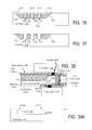
- FIGS. 36, 37 show vertical cross sections of optical interposers during fabrication according to some embodiments of the present invention.
- FIG. 38 shows a vertical cross section of a module with an optical interposer according to some embodiments of the present invention.
- FIGS. 39A, 39B, 39C show vertical cross sections of optical interposers during fabrication according to some embodiments of the present invention.
- FIG. 40 is a top view of an optical interposer during fabrication according to some embodiments of the present invention.
- FIGS. 41, 42 show vertical cross sections of optical interposers with fibers according to some embodiments of the present invention.
- FIGS. 43, 44A are top views of optical interposers during fabrication according to some embodiments of the present invention.
- FIG. 44B shows a side view of an optical interposer according to some embodiments of the present invention.
- FIG. 45 shows a vertical cross section of an optical interposer according to some embodiments of the present invention.
- FIG. 46 shows a vertical cross section of an optical interposer with fibers according to some embodiments of the present invention.
- FIGS. 47, 48A, 48B, 48C, 48D show vertical cross sections of optical interposers during fabrication according to some embodiments of the present invention.
- FIG. 48E is a top view of an optical interposer during fabrication according to some embodiments of the present invention.
- FIG. 49 shows a vertical cross section of an optical interposer during fabrication according to some embodiments of the present invention.
- FIGS. 50, 51 show vertical cross sections of modules with optical interposers and fibers according to some embodiments of the present invention.
- FIG. 52A shows a vertical cross section of an optical interposer during fabrication according to some embodiments of the present invention.
- FIG. 52B is a top view of an optical interposer during fabrication according to some embodiments of the present invention.
- FIGS. 53, 54 show vertical cross sections of optical interposers during fabrication according to some embodiments of the present invention.
- FIGS. 55A, 55B show vertical cross sections of modules with optical interposers and fibers according to some embodiments of the present invention.
- FIG. 56 is a top view of an optical interposer during fabrication according to some embodiments of the present invention.
- FIGS. 57, 58 show vertical cross sections of optical interposers during fabrication according to some embodiments of the present invention.
- FIG. 59 shows a vertical cross section of a module with an optical interposer and fibers according to some embodiments of the present invention.
- FIGS. 60, 61 show vertical cross sections of sensors with vertical interposers according to some embodiments of the present invention.
- FIG. 62 shows a vertical cross section of a multi-chip module with an interposer used for optical interchip communications according to some embodiments of the present invention.
- FIGS. 63A, 63B, 63C, 63D, 63E show vertical cross sections of optical interposers during fabrication according to some embodiments of the present invention.
- FIGS. 6A-6C illustrate one embodiment of the present invention in the same cross sectional view (transversally to the fibers) as in FIG. 3 .
- grooves (fiber channels) 310 are formed by two etches as follows:
- a cavity 410 is etched in substrate 130 .
- This cavity will eventually house all the fibers 104 .
- the cavity sidewalls can be inclined at 45° or some other angle “ ⁇ ” to provide mirrors (provided by silicon 130 or a separate layer not shown in FIG. 6A ) or other elements.
- the cavity is then filled with some material 520 ( FIG. 6B ).
- Layer 520 is then patterned and etched to form grooves 310 ( FIG. 6C ).
- the etch is selective to substrate 130 . Due to the etch selectivity, the 45° sidewall providing or supporting the mirrors will not be damaged by the etch even though the sidewall is exposed early during the etch.
- the process is tolerant to misalignment between the cavity mask (the etch mask, not shown, used to form the cavity in FIG. 6A ) and the groove mask (not shown) because the cavity mask can be shifted right or left in the view of FIG. 6C relative to the groove mask.
- Cavity 410 ( FIG. 6A ) has a low aspect ratio (height-to-depth ratio), so the etch of cavity 410 can be easily controlled to provide a precise uniform depth throughout the cavity. In some embodiments, the aspect ratio is at most 1:2.
- the etch of layer 520 can also be easily controlled because this etch is selective to substrate 130 serving as an etch stop.
- substrate 130 can be silicon, and layer 520 silicon dioxide.
- the etch selectivity can be improved by forming an additional etch-stop layer on cavity 410 before deposition of layer 520 . In some embodiments, the etch selectivity is at least 2:1.
- the process of FIGS. 6A-6C is easy to integrate with other steps that form conductive lines or other circuitry in or over substrate 130 .
- Such circuitry can be formed between the stages of FIGS. 6B and 6C , i.e. after the deposition of layer 520 before the groove etch.
- the wafer is flat at this stage, and many conventional processes for circuit fabrication work better on flat wafers. (We will sometimes refer to substrate 130 together with other elements integral with the substrate as a “wafer”; in some embodiments multiple interposers are simultaneously fabricated in the same wafer.) In particular, wafer handling and photolithography work better with flat wafers.
- the material 520 can be chosen consistently with the processes forming other circuitry.
- the material 520 can be chosen to withstand high temperatures. If mirrors 144 (not shown in FIGS. 6A-6C ) or other elements need to be formed of non-refractory metal (such as gold), the metal deposition can be postponed until after the high temperature steps.
- FIG. 7 is a view of an interposer 124 with a mirror 144 and a fiber or fibers 104 in a cross section taken along a fiber 104 .
- the fibers are inserted into grooves 310 so that they project beyond the cavity at the interposer's left side.
- the cavity 410 does not have a sidewall on that side.
- the cavity is initially formed with the sidewalls on all sides ( FIG. 6A ), but one side is then removed during dicing of wafer 130 . More particularly, one sidewall of cavity 410 is positioned on the wafer's scribe line. This sidewall is removed by the dicing process.
- FIG. 8 top view
- FIG. 9A cross sectional view
- FIG. 9B top view
- substrate 130 can be silicon, silicon on insulator (SOI), glass, metal, or other materials.
- SOI silicon on insulator
- substrate 130 is part of a wafer in which multiple interposers are simultaneously fabricated.
- substrate 130 is monocrystalline silicon having a thickness of 750 ⁇ m.
- Substrate 130 is initially planar on top and bottom. Cavity 410 is formed by a masked timed etch. More particularly, substrate 130 is cleaned, and a masking layer 810 is deposited on the entire top surface to provide a hard mask.
- layer 810 is silicon dioxide thermally grown to an exemplary thickness of 1.0 ⁇ m, but other materials (e.g. silicon carbide, silicon nitride, metal, and others) and other fabrication processes can also be used. Layer 810 can also form on the wafer's bottom and sidewall surfaces though this is not shown. (Layer 810 is optional, and can be omitted; the hard mask may or may not be desirable depending on the type of etch used to form the cavity, the cavity depth, the material of substrate 130 , and possibly other factors.)
- Masking layer 810 is patterned to define cavity 410 . See FIG. 8 .
- the photoresist is removed, and substrate 130 is etched through the mask opening to form the cavity.
- the cavity has a horizontal bottom surface (parallel to the substrate's bottom surface) and sloped sidewalls 910 . 1 through 910 . 4 that are inclined at an exemplary angle of 45° to the bottom surface of the substrate.
- the mirrors will be formed on one or more of these sidewalls, e.g. on sidewall 910 . 2 .
- the invention is not limited to a cavity having four sidewalls; the cavity can be non-rectangular in top view, and may have rounded and other shapes.
- An exemplary etch of cavity 410 is an anisotropic wet etch which provides the 45° sidewalls if wafer 130 is a (100)-silicon wafer and the opening in mask layer 810 , as shown in FIG. 8 , exposes a rectangular region of the top surface of substrate 130 with the sides oriented in the ⁇ 100> directions of the silicon crystal.
- a suitable wet etch is the same etch as described above in connection with FIG. 3 , i.e. KOH with isopropyl alcohol (IPA) as an additive.
- the sloped sidewalls 910 . 1 - 910 . 4 are ⁇ 110 ⁇ planes, and the etch is selective to such planes as described above. The etch is timed to provide the desired cavity depth.
- the cavity depth is 100 ⁇ m, and the etching time is about 100 minutes.
- the etchant is a solution of TMAH (Tetramethylammonium hydroxide) or of EDP (Ethylene-diamine-pyrocatechol).
- the etching technique may be chosen based on many factors, such as desired surface morphology (related to roughness of the mirror), the material and thickness of mask 810 , etching selectivity to the mask material, parasitic planes size (i.e. the size of undesired planes that may form in substrate 130 during the etch), etching rates, defect density, material cost, process cost, limitations on use and disposal of etching byproducts, and others factors.
- Example etching techniques include:
- the cavity depth can be any suitable value, e.g. 100 to 500 ⁇ m or smaller or larger.
- the cavity is rectangular, and the dimensions of the cavity's top surface are 2.1 mm along the sidewall 910 . 1 and 2.0 mm along the sidewall 910 . 2 .
- the aspect ratio of the cavity is thus about 1:21.
- the low aspect ratio is desirable to provide a uniform, highly controllable cavity depth.
- Other shapes, dimensions and aspect ratios can also be used.
- Different sides of the rectangular opening in mask 810 may have different orientations; in some embodiments, the mirror 144 will be formed on side 910 . 2 , and this side has a ⁇ 110> orientation when mask 810 is formed, but other sides may have other orientations, and non-rectangular cavities can also be used.
- etch stop layer 1010 ( FIG. 10 ) is deposited over the substrate to provide an etch stop in subsequent etch of layer 520 ( FIGS. 6B, 6C ).
- layer 520 will be polysilicon
- layer 1010 is silicon dioxide thermally grown on silicon substrate 130 to a thickness of 2.0 ⁇ m or deposited by CVD (chemical vapor deposition, e.g. from TEOS). The thickness of layer 810 increases in this step.
- layer 520 is chosen for compatibility with other fabrication processes that will form circuitry in substrate 130 .
- Polysilicon is desirable for its tolerance to high temperatures such as present in thermal oxidation of silicon. Polysilicon is also easy and inexpensive to deposit.
- layer 520 will be used to provide mechanical support for a cantilevered transducer 120 as described below but will not be used to provide semiconductor circuit elements such as transistor regions. Low quality polysilicon and inexpensive deposition methods can therefore be used.
- layer 520 can be metallurgical polysilicon formed by LTCVD (Low Temperature Chemical Vapor Deposition). Another possibility is polysilicon deposited by high temperature (1200° C.) CVD. Other processes can also be used.
- Layer 520 can be amorphous silicon or polysilicon having very small fine size (nano-grain), or can be epitaxially grown silicon, or other kind.
- suitable materials include polyimide and photoresist (especially if high temperatures will not be used). Other materials are also possible.
- one or more (possibly all) process steps that form the circuitry in substrate 130 are performed before or during the deposition of layer 520 , and the material for layer 520 is chosen based on other considerations.
- the material is a polymer, possibly a particulate polymer, e.g. with glass-bead particles for mechanical reinforcement. Metals and other materials can also be used.
- Layer 520 initially covers the whole wafer, but then is polished by chemical mechanical polishing (CMP) stopping on oxide 810 . See FIG. 11 . Cavity 410 remains filled by layer 520 but layer 520 is removed outside the cavity. In other embodiments, the CMP or other process leaves layer 520 covering the entire wafer, with a planar top surface. (A non-planar top surface is also possible.)
- CMP chemical mechanical polishing
- the wafer Before etching the layer 520 to form the grooves 310 , the wafer is processed to form circuitry for connection to transducer or transducers 120 and possibly for other purposes.
- the wafer is planar at the stage of FIG. 11 , as desirable for many IC fabrication processes. If desired, an additional planar layer (e.g. silicon nitride) can be deposited over the wafer as a protective layer to protect the layer 520 .
- the wafer can be processed to create circuitry 134 ( FIG. 1 ) or any other desired circuitry, including for example circuit elements both at the top and the bottom of substrate 130 , with through-wafer interconnects between such circuit elements. See for example the following U.S. patents incorporated herein by reference:
- a via 1210 ( FIG. 12 ) is formed in the top surface of substrate 130 at each location of a desired through-substrate via (through-silicon via if the substrate is made of silicon). The via initially does not go through the substrate, but is deeper than the substrate's final thickness (the substrate will be thinned as described below).
- a silicon dioxide layer 1220 is grown over the substrate by thermal oxidation, at an exemplary temperature of 1100° C. for 160 minutes to an exemplary thickness of 1.0 ⁇ m. Layer 1220 also forms on polysilicon 520 unless polysilicon 520 is covered by a protective layer described above in connection with FIGS. 10-11 but not shown in the figures. The thermal oxidation increases the thickness of oxide 810 if this oxide is not covered by the protective layer.
- a seed layer 1230 e.g. copper
- a photoresist film 1240 e.g. dry-film-resist
- Copper 1250 is electroplated to fill the vias 1210 and protrude above the resist 1240 .
- FIG. 13 A subsequent stage is illustrated in FIG. 13 . More particularly, copper 1250 is polished by CMP to provide a planar top surface. Then resist 1240 is stripped, and copper layers 1250 and 1230 are polished down by CMP to the level of oxide 1220 . Oxide 1220 becomes exposed. (Both layers 1250 , 1230 remain in vias 1210 but are shown simply at 1250 in some drawings.) Another metal layer 1310 is sputtered on the wafer and patterned photolithographically to form conductive lines that will connect the metalized vias 1210 (i.e. the copper in vias 1210 ) to transducer contacts and/or other circuit elements (e.g. transistors, resistors, diodes, capacitors, or other elements that can be formed in the interposer).
- circuit elements e.g. transistors, resistors, diodes, capacitors, or other elements that can be formed in the interposer.
- Metal pads 1310 are also formed on oxide 1220 over cavity 1410 to provide mechanical support for cantilevered transducers as described below. These and other metal pads may or may not be part of electrical circuitry and may or may not be connected to other circuit elements. Additional dielectric and metal layers (not shown) can be deposited to create multiple interconnect layers and other circuit elements for circuitry connected to the transducers and for other circuitry. Then a passivation layer 1330 (e.g. polyimide) is formed to cover the top side of the wafer.
- a passivation layer 1330 e.g. polyimide
- FIG. 14 the wafer is thinned to turn the vias 1210 into through-vias (through holes). Copper 1250 (and 1230 ) and insulator 1220 protrude down from substrate 130 . Then insulator 1410 (e.g. polyimide) is deposited on the bottom surface, and the bottom surface is planarized by CMP which does not remove all of insulator 1410 but exposes the copper. See FIG. 15 .
- insulator 1410 e.g. polyimide
- Metal 1420 (e.g. copper) is deposited (e.g. by physical vapor deposition, “PVD”) on the bottom surface of the wafer. Metal 1420 is patterned photolithographically to provide interconnect lines for connecting the metalized vias to a controller chip (shown in FIGS. 22A, 22B ) that will control the transducers 120 , and possibly to provide other interconnect lines or other circuit elements. Other interconnect layers (not shown) and other circuit elements (e.g. transistors, diodes, resistors, capacitors, etc., not shown) can also be formed at the bottom.
- PVD physical vapor deposition
- a passivation layer 1430 (e.g. polyimide) is deposited on the bottom surface and is patterned photolithographically to form contact openings exposing the metal 1420 . See FIG. 16 .
- the exposed portions of metal 1420 form contact pads that can be soldered or otherwise attached to the controller chip or other circuits.
- FIG. 17A is a top view of the resulting structure
- FIG. 17B shows the wafer's cross section perpendicular to the grooves.
- the wafer is covered with photoresist (not shown), and the photoresist is patterned to define grooves 310 and the contact openings to metal 1310 ( FIG. 16 ).
- Passivation 1330 is etched away through the photoresist openings over the grooves to be formed and in the contact openings. Oxide 1220 becomes exposed over the grooves 310 . (Alternatively, the etch of passivation 1330 can remove the oxide 1220 over the grooves and expose the layer 520 ).
- the photoresist is removed, and another photoresist layer (not shown) is deposited and patterned to define the grooves 310 . If oxide 1220 was not removed over the grooves, it is removed at this time to expose layer 520 in the grooves.
- Layer 520 is etched selectively to the photoresist and to layer 1010 to form the grooves and expose the layer 1010 .
- the groove sidewalls are vertical, but non-vertical sidewalls are formed in other embodiments.
- layer 520 is polysilicon etched by DRIE (deep reactive ion etch), possibly the Bosch process, and layer 1010 is silicon dioxide. The etch selectivity of polysilicon to silicon dioxide is at least 100:1. Other fabrication processes and selectivity values can also be used.
- Exemplary dimensions that can be achieved for rectangular grooves 310 with monocrystalline substrate 130 and polysilicon spacers 520 , using silicon oxide 1010 as an etch stop, are as follows: the groove width is 135 ⁇ m; the groove pitch (the distance between the centers of adjacent grooves) is 250 ⁇ m; the groove depth is 100 ⁇ m. In some embodiments with rectangular grooves, a suitable groove width is 50 to 1000 ⁇ m, the groove pitch is 150 to 2000 ⁇ m, and the groove depth is 100 to 500 ⁇ m. Other ranges are also possible.
- a reflective layer e.g. aluminum, gold, or some other metal
- the mirrors are formed by depositing a stack of layers with different refractive indices.
- the mirrors are initially formed on a separate substrate (not shown), but then are released from that substrate and are attached to sidewall 910 . 2 by adhesive.
- a stack of layers is formed on the separate substrate as follows: a polysilicon layer is deposited, is covered with a dielectric layer (e.g.
- the wafer is diced.
- the left sidewall 910 . 4 of cavity 410 is on a dice line, so the sidewall 910 . 4 is removed. See FIG. 19 .
- the grooves 310 become exposed on the left for fiber insertion.
- Fibers 104 are inserted into the grooves as shown in FIG. 20 .
- Transducer 120 and possibly other circuits are connected to the interposer (to metal contacts 1310 , 1420 ). In the exemplary embodiment of FIGS.
- transducer 120 is flip-chip attached to the top contacts 1310 of the interposer with solder 1604 or some other means
- controller 1610 is flip-chip attached to the bottom contacts 1420 with solder 1608 or some other means.
- FIG. 21 is the top view;
- FIG. 22A shows a longitudinal cross section along a spacer 520 / 1220 / 1330 between adjacent grooves 310 ;
- FIG. 22B shows a cross section along a fiber 104 .
- Multiple transducers, controllers, and other integrated circuits and discrete circuit elements can be connected to the interposer. As seen in FIG.
- solder 1604 is also placed on metal 1310 over polysilicon spacers 520 to provide mechanical support for supporting cantilevered transducer chip or chips 120 or other circuits that may overly the cavity 410 .
- the transducer size can therefore be increased without increasing the stress on the transducer and without increasing the overall area of the module.
- the module can be mounted on a PCB or in any other desired way.
- mirrors 144 can be initially manufactured on a separate substrate (such mirrors are called “separately made” below).
- the separately made mirrors be mounted at a 45° angle, or some other angle, independently of the cavity sidewall angles.
- FIGS. 23A, 23B Some embodiments are illustrated in FIGS. 23A, 23B . These figures show vertical cross sections by the same cross sectional planes as in FIGS. 22A, 22B (i.e. passing through a spacer 520 and a fiber 104 respectively). The transducer and the controller are not shown for simplicity.
- the cavity sidewall 910 . 2 is vertical, but could be at any angle greater than or equal to 45°, including for example a retrograde angle as in FIG. 4 .
- Substrate 130 can be a silicon wafer of any crystal orientation, or can be polysilicon or a non-silicon material.
- the fabrication process can be essentially as described above in connection with FIGS. 6A-22B .
- Spacers 520 are spaced from cavity sidewall 910 . 2 to leave room for the mirrors—this spacer geometry can be provided by the spacer etch of FIG. 6C or 17A-17B or by spacer patterning at any other suitable stage.
- the minors 144 can be a single continuous separately-made reflective strip supported by the top edge of sidewall 910 . 2 and the bottom edge of spacers 520 .
- Mirror strip 144 is fixed in place by adhesive for example.
- the cavity may include extensions (not shown) adjacent to the minor, e.g. dog-bone extensions at the cavity sides 910 . 1 , 910 . 3 , to facilitate mirror placement into the cavity.
- the mirrors in different grooves 310 can be provided by multiple strips rather than a single strip.
- the mirror is supported at the bottom by a step 2310 in the bottom surface of cavity 410 .
- the step can be formed using a suitable etch of substrate 130 .
- a separately made mirror 144 may be a surface of a three-dimensional shape such as a pyramid 2320 (see FIG. 23D showing a vertical cross section along a fiber).
- the mirror is the fiber-facing surface of the pyramid.
- the mirror is the back surface of a collimating lens 2330 which collimates the beam 140 going out of the fiber 104 .
- the beam may also travel in the opposite direction.
- Other mirror structures and optical elements can also be provided.
- each spacer 520 can be made discontinuous and/or hollow.
- discontinuous spacers can define multiple channels overlying each other, as illustrated in FIG. 24 (top view without fibers and transducers), FIG. 25 (top view with two layers of fibers 104 but without transducers), and FIG. 26 (top view with two layers of fibers 104 and two transducers 120 ). In FIGS. 25 and 26 , contacts 1310 between the grooves are not shown for simplicity.
- Grooves 310 X and fibers 104 X run in the X direction (horizontally in the view of FIGS. 24-26 ) between the spacers. Grooves 310 Y and fibers 104 Y run in the Y direction over the fibers 104 X.
- Mirrors 144 on side 910 . 2 are for the bottom fibers 104 X.
- Mirrors 144 on side 910 . 1 are for the top fibers 104 Y.
- Cavity sidewalls 910 . 3 , 910 . 4 are removed during dicing or at some other processing stage.
- FIGS. 27A, 27B, 27C are top views of some embodiments of cavity 410 with continuous and discontinuous spacers 520 and with fibers. (In these embodiments, mirrors 144 merge into a continuous layer on the cavity sidewall; the spacers do not overly the sidewall.)
- FIG. 27A shows discontinuous rectangular spacers.
- FIG. 27B shows discontinuous circular spacers.
- FIG. 27C shows continuous hollow spacers.
- FIG. 27D shows some non-limiting examples of individual spacers in top view: A (round spacer, as in FIG.
- Spacer J is another hollow rectangle, but the spacer is continuous, i.e. running through the whole cavity (as in FIG. 27C ).
- Other shapes can also be used.
- the spacers' sidewalls can be vertical or inclined, and can have conical or other shapes.
- spacers 520 between each pair of fibers 104 form a double row of discontinuous spacers.
- FIGS. 29-30 illustrate use of SOI (silicon on insulator) substrate 130 , having monocrystalline silicon layers 130 . 1 , 130 . 2 separated by planar insulating layer 2910 .
- Layer 2910 can be silicon dioxide, silicon nitride, a polymer, or any other suitable material, possibly a combination of different materials.
- the fabrication process is similar to the processes described above.
- FIGS. 29-30 show the same views, and the same stages of fabrication, as respective FIGS. 8, 11 .
- the etch of cavity 410 stops on insulator 2910 , and so will the etch of grooves 310 (described above in connection with FIG. 17B ). Highly controllable cavity depth is achieved.
- layer 130 . 2 has (100) orientation
- the openings in mask 810 are rectangular with ⁇ 100> sides
- the cavity etch is a KOH wet etch described above that forms 45° sidewalls.
- FIG. 31 is similar to FIG. 18 , but minors 144 are formed at the groove ends on cavity sidewalls 910 . 2 , 910 . 4 .
- Transducers (not shown) can be mounted on the interposer over all these minors, and can be optically coupled to each other by the optical fibers 104 .
- mirrors and transducers can be provided on all the four cavity sides 910 . 1 - 910 . 4 .
- a single transducer chip may have both light emitters and photodetectors.
- the grooves can be curved in the top and/or side views, and can have a varying width.
- the minors 144 can be provided by the surfaces of substrate 130 , or can be absent since mirrors can be etched into fibers' end faces as described in U.S. Pat. No. 8,031,993 issued Oct. 4, 2011 to Bowen.
- the minors 144 when present, can be planar as described above, or can be elliptic or have other shapes.
- Non-minor optical elements e.g. prisms, etc.
- the spacers can be formed by a subtractive method as shown in FIGS. 32A-32C .
- FIG. 32A is similar to FIG. 6C , but layer 520 is patterned to remain at the groove locations, i.e. in regions complimentary to the spacer locations. The patterning uses a selective etch as in FIG. 6C . Then the gaps between the features of layer 520 are filled with a material 3410 ( FIG. 32B ).
- This can be any material suitable for the spacers, deposited by any suitable process, e.g. metal deposited over the wafer and then etched off to provide a planar top surface. Other techniques can also be used, e.g. electrodeposition on a seed layer (not shown) formed in the cavity before deposition of layer 520 .
- layer 520 is etched away selectively to layer 3410 ( FIG. 32C ) to form the grooves 310 .
- Layer 3410 provides the spacers between the grooves.
- the subtractive method can be used with an etch-stop layer such as 1010 ( FIG. 17B ) and can be combined with other features described above.
- the wafer is processed as described above in connection with FIGS. 8, 9A, 9B, 10 .
- a seed layer 3420 ( FIG. 33A ) is deposited on the wafer for electroplating.
- the material, thickness and deposition method of the seed layer will depend on the material 3410 to be later electroplated.
- seed 3420 and layer 3410 are the same material. e.g. metal, and the seed layer is deposited by sputtering or chemical vapor deposition (CVD).
- an adhesion layer 3416 is formed on the wafer before the seed layer deposition.
- the seed layer is nickel, tungsten, copper, aluminum, titanium, or their alloys (e.g. a nickel-tungsten alloy) the adhesion layer can be titanium or chromium deposited by sputtering or evaporation to a thickness of 2.5 nm to 100 nm.
- Layer 520 is then deposited on the wafer and is patterned as described above in connection with FIG. 32A . Any suitable material can be used as described above. In an exemplary embodiment, layer 520 is photoresist covering the whole wafer except where it is removed by patterning. Then layer 3410 ( FIG. 33B ) is electroplated on the exposed portions of seed layer 3420 . In some embodiments, electroplating terminates when the top surface of layer 3410 is below the top surface of layer 520 but this is not necessary. Layer 520 is removed from the wafer ( FIG. 33C ). Optionally, seed layer 3420 and possibly adhesion layer 3416 are removed from the wafer areas not covered by spacers 3410 . (In some embodiments, layer 520 is not removed outside the grooves, and thus layer 520 remains at the left and right cavity edges to the left and right of grooves 310 in the view of FIG. 33C .)
- FIG. 33D shows an exemplary vertical cross section along a spacer 3410 .
- the mirrors are formed by a lift-off method.
- spacers 3410 do not extend over the sloped sides 910 of cavity 410 in order to obtain a planar top surface in layer 3410 in the electroplating process (at the stage of FIG. 33B ).
- the lift-off method uses a photoresist layer 3430 deposited and patterned to define the mirrors.
- the photoresist is patterned to expose the entire cavity side 910 . 2 .
- layer 144 is deposited on the wafer, and then the photoresist 3430 is removed. Layer 144 covers the entire side 910 . 2 .
- FIG. 33E shows a vertical cross section of the resulting structure along a spacer 3410 .
- circuit elements e.g. metalized vias as in FIG. 22A
- Other circuit elements can be formed before the etch of cavity 410 or at any other suitable stage.
- the spacers can partially or completely cover the fibers 104 as shown in FIGS. 34A and 34B .
- FIG. 34B is a top view
- FIG. 34A is a vertical cross section perpendicular to the fibers, along the line A-A′ marked in FIG. 34B .
- Metalized vias and other circuitry are not shown.
- the spacers are shown at 3410 (the invention is not limited to any reference numerals).
- the spacers 3410 form stripes perpendicular to the fibers, but in other embodiments the spacers 3410 have other geometry, and in some embodiments form a single, continuous structure overlying the cavity, with channels 310 for the fibers. Separate stripes as in FIG. 34B or other discontinuous spacer shapes can be helpful for thermal stability and for facilitating insertion of fibers 104 into fiber channels 310 .
- FIG. 34C (vertical cross section by the same plane as in FIG. 34A ) illustrates an exemplary method of fabrication.
- the spacers are formed by a subtractive method as in FIGS. 32A-32C .
- the wafer is processed as in FIGS. 8, 9A, 9B, 10 to form cavity 410 with layers 810 , 1010 .
- a layer 520 is deposited and patterned to remain at the locations of fiber channels 310 .
- layer 3410 is deposited to cover the layer 520 and to form spacers between the features of layer 520 .
- layer 3410 can be patterned to form stripes as in FIG. 34B or other discontinuous shapes.
- layer 520 can be formed to extend into selected areas between the channels 310 to prevent formation of spacers 3410 in such areas.
- layer 520 is removed from over cavity 410 (and possibly elsewhere) by a wet etch to obtain the structure of FIG. 34A .
- Layer 3410 can be patterned before or after removal of layer 520 .
- FIGS. 34D-34E Another fabrication process is illustrated in FIGS. 34D-34E .
- Spacers 3410 are formed by electroplating as in FIGS. 33A-33C . More particularly, the wafer is processed as in FIG. 33A .
- Layer 520 will serve as an electroplating mask, and in the embodiment of FIG. 34D layer 520 covers the entire wafer except for the locations of channels 310 .
- layer 3410 is electroplated onto seed layer 3420 as described above in connection with FIG. 33B , except that the electroplating process continues until the layer 3410 overlaps the mask 520 .
- the adjacent features (spacers) 3410 do not meet above the mask 520 , so the channels 310 are not completely covered on top; FIG.
- 34E shows the structure after removal of layer 520 and insertion of fibers 104 into channels 310 ; the spacers 3410 partially overlie the channels and the fibers.
- layer 3410 is electroplated until the adjacent features 3410 meet over mask 520 , so the channels 310 and the fibers are covered on top as in FIG. 34A .
- spacer layer 3410 can be patterned to provide discontinuous spacers as in FIG. 34B for example. Also, layer 520 can be formed to extend into selected areas between the channels 310 to prevent formation of spacers 3410 in such areas. Then mirrors 144 can be formed as described above.
- the fiber position is more secure.
- grooves with optical fibers are provided both at the top and bottom surfaces of the interposer.
- the grooves at each surface can be formed using any techniques described above, including the prior art techniques described in connection with FIGS. 1-3 .
- One exemplary process is as follows. Substrate 130 is thinned to its final thickness. Then V-grooves or other grooves are etched in substrate 130 on both sides, possibly simultaneously, possibly with a wet etch. Then each side is processed, possibly as the top side in FIG. 1-3 , to finish the interposer fabrication.
- the interposer is formed as follows.
- Substrate 130 is thinned to its final thickness.
- cavities 410 . 1 , 410 . 2 are etched respectively in the top and bottom surfaces of the substrate, possibly simultaneously, using the processes described above or any other suitable processes.
- a mask 810 is used on the top and bottom to define the two cavities.
- Etch stop layer 1010 is formed on the top and bottom surfaces, possibly simultaneously (e.g.
- layer 520 is formed on the top and bottom surfaces of the wafer using the techniques described above or other techniques. This layer is shown as 520 . 1 on the top surface, and as 520 . 2 on the bottom surface.
- the top layer 520 . 1 is planarized as in FIG. 11 , to be removed outside of cavity 410 . 1 .
- the bottom layer may also be planarized, but it covers the whole bottom surface of the wafer.
- the thickness is chosen to accommodate the through-substrate-via process described below, and can be any suitable value.
- a blind via 1210 is formed in the top surface of the wafer by a masked etch of layer 810 and substrate 130 at each location of a desired through-substrate via as described above in connection with FIG. 12 .
- Via 1210 passes through substrate 130 and through layer 810 above and below the substrate and partially, but not completely, passes through layer 520 . 2 .
- vias 1210 are then oxidized and metalized, and conductive lines 1310 and possibly other circuit elements and passivation 1330 are formed on top of the interposer, using processes described above in connection with FIGS. 12-13 .
- the interposer is thinned, by CMP or other processes, to remove the layer 520 . 2 down to the level of oxide 1010 at the interposer bottom.
- Vias 1220 become through holes.
- Copper 1250 (and seed 1230 ) and insulator 1220 protrude down from substrate 130 .
- insulator 1410 e.g. polyimide
- CMP chemical vapor deposition
- Conductive lines 1420 and other circuit elements and passivation 1430 are formed on the interposer bottom as described above in connection with FIGS. 15-16 and illustrated in FIG. 35D .
- FIG. 35E shows an exemplary vertical cross section perpendicular to grooves 310 .
- the cavities 410 . 1 , 410 . 2 do not have to be aligned, i.e. cavity 410 . 1 can be laterally shifted relative to cavity 410 . 2 .
- the grooves 310 also may have different shapes and dimensions. More than one cavity can be provided on top and/or bottom, and the top grooves 310 do not have to be parallel to the bottom grooves.
- FIG. 35F shows an exemplary structure at a stage similar to FIG. 22B , with transducers 120 . 1 , 120 . 2 on top and bottom respectively.
- the two transducers are connected to each other through a metalized via 1210 , but this is not necessary.
- Different transducers can be connected to different vias, or not connected to any vias, and controllers 1610 ( FIG. 22A ) and other circuits can be mounted on the interposer as needed.
- the through vias 1210 are created without first forming blind vias, i.e. the vias 1210 are etched through the interposer wafer right away. Also, the invention is not limited to through vias.
- FIG. 36 shows a variation of the method of FIGS. 6A-6C .
- layer 520 is covered by a layer 3610 made of a different material than 520 , possibly of the same material as the cavity surface.
- Layer 3610 can be formed on layer 520 by selective deposition, or can be deposited to a greater thickness on top of layer 520 than on the cavity bottom and can be anisotropically etched until it is removed from the cavity bottom, or layer 3610 can be left on the cavity bottom (this is not shown in FIG. 36 ).
- the sidewalls of spacers 520 or 3410 can be at any angle 13 ( FIG. 37 ) to the cavity's bottom surface. In some embodiments, this angle is 90° or some other angle of at least 85°.
- At least one spacer protrudes upward to provide mechanical support for at least one of the transducers.
- FIG. 38 showing a structure similar to FIG. 22A but without the metal 1310 and solder 1604 over the cavity.
- Transducer 120 rests on passivation 1330 above spacer 520 .
- layer 520 can be left to protrude upward above substrate 130 .
- Layer 520 can then be etched off outside the cavity as needed to form the electrical circuitry. The upward protrusion of layer 520 at the cavity will result in the upward protrusion of passivation 1330 over the cavity.
- the “mirror” sidewalls can be formed by a separate etch or other process.
- mirror sidewall 910 . 2 can be at a different angle and/or depth than sidewalls 910 . 1 , 910 . 3 , 910 . 4 .
- FIGS. 39A-39C One possible process is illustrated in FIGS. 39A-39C . This process is suitable for a wide variety of substrate materials including monocrystalline silicon and other materials described above. Initially ( FIG. 39A ), cavity 410 is formed with all the sidewalls being vertical or at some other angle.
- the cavity is formed by a masked dry etch with a photoresist mask (not shown, similar to mask 810 in FIG. 8 ). Then ( FIG. 39B ) the photoresist is removed, and sidewall 910 . 2 is etched to change its geometry. Other sidewalls of the cavity may or may not be similarly processed, and either an entire sidewall or only part of a sidewall may be so processed.
- the geometry of sidewall 910 . 2 is defined by mechanical machining, and more particularly using a dicing saw 3910 having a 45° sidewall 3910 A facing the sidewall 910 . 2 .
- Saw 3910 rotates around a horizontal axis 3910 X perpendicular to sidewall 910 . 2 to change the sidewall geometry. Sidewall 910 . 2 acquires a 45° profile matching the saw sidewall 3910 A. See FIG. 39C (vertical cross section) and FIG. 40 (top view).
- the cavity can be filled with layer 520 , possibly after deposition of layer 1010 , and such cavities can be formed both at the top and the bottom of substrate 130 by the process of FIGS. 39A-39C or other processes.
- the sawing or other processing of sidewall 910 . 2 ( FIG. 39B ) is performed to a controlled depth, and in the embodiment of FIG. 39C the depth is less than the depth of cavity 410 .
- This step can be used as a hard stop for fibers 104 to facilitate the fiber alignment as shown in FIG. 41 —the fibers are inserted in grooves 310 so that they abut the step 3930 .
- FIG. 41 does not show oxide 1010 and other features that may or may not be present as in FIGS. 6A-38 .
- the mirror sidewall 910 . 2 can be deeper than the rest of the cavity, or can be of the same depth.
- the cavity with grooves 310 and the electrical circuitry can initially be formed in separate wafers, shown as interposers 124 . 1 and 124 . 2 , which are then assembled into a single optical interposer 124 .
- An exemplary fabrication process is as follows.
- Optical interposer 124 . 1 is fabricated by processing a substrate 130 . 1 (monocrystalline silicon or other suitable material) as in FIGS. 8-19 to form cavity 410 and grooves 310 and mirrors 144 , but without electrical circuitry outside the cavity 410 .
- Oxide 1220 , metal 1310 , and passivation 1330 may be present in interposer 124 . 1 in the cavity area as in FIGS. 17A-19 .
- Circuit elements and pads of metal 1310 can thus be formed in the cavity area. Then the wafer is thinned and diced to obtain a structure containing the cavity as shown in top view in FIG. 43 . One or more sidewalls may (but does not have to) be removed in the dicing process as described above in connection with FIG. 19 . Process variations can be used as described above, including the variation of FIGS. 39A-39C .
- interposer 124 . 2 is fabricated by processing a substrate 130 . 2 (monocrystalline silicon or other suitable material) to form electrical circuitry for connection to transducers and other circuits.
- the wafer processing can be as described above in connection with FIGS. 12-16 .
- a cavity 4210 is formed in substrate 130 . 2 .
- Optical interposer 124 . 1 is inserted into this cavity and affixed to the cavity, e.g. by adhesive or otherwise.
- Fibers 104 can be inserted in grooves 310 and suitably affixed (e.g. with adhesive) before or after the attachment of interposer 124 . 1 to interposer 124 . 2 .
- Transducers and other circuits can be attached to combined interposer 124 as described above.
- Interposer 124 . 1 may have discontinuous spacers and/or mirrors 144 on different sidewalls as FIGS. 24-26 , and interposer 124 . 1 or 124 may have other features described above in connection with FIGS. 6A-41 .
- interposer 124 . 2 has cavities 4210 on top and bottom, and a separate interposer or interposers 124 . 1 are inserted into each cavity.
- FIGS. 44A-46 illustrate another embodiment, in which the interposer 124 . 1 is a just a substrate supporting the spacers.
- the substrate is shown at 4410 and the spacers at 4420 .
- FIG. 44A is a top view of interposer 124 . 1
- FIG. 44B is a side view.
- the spacers define channels 310 .
- the substrate and spacers are an integral structure formed by a masked etch of the substrate.
- the substrate can be silicon, polysilicon, or any other suitable material.
- the entire interposer 124 . 1 is made of a photosensitive material, e.g. photoresist or photosensitive polymer. In some embodiments, the entire interposer 124 .
- spacers 4420 can be made of a thin film deposited on substrate 4410 and patterned. Other processes can also be used. Also, the spacers may have any shape discussed above, including discontinuous shapes as in FIGS. 27A-28 , or the shapes overlying the channels 310 as in FIGS. 34A-34E .
- Interposer 124 . 2 ( FIG. 45 ) can be manufactured using any techniques discussed above for interposers 124 except that the interposer 124 . 2 does not need spacers.
- FIG. 45 shows a vertical cross section of an exemplary interposer 124 . 2 like one described above in connection with FIG. 22B but without the spacers.
- the interposer 124 . 2 can be manufactured as described above but with the spacer etch of FIG. 17A being replaced by complete removal of layer 520 .
- FIG. 46 (same vertical cross section as in FIG. 45 )
- interpose 124 . 1 is then affixed within cavity 410 of interposer 124 . 2 , e.g.
- Interposer 124 . 1 can be larger or smaller than cavity 410 .
- interposer 124 . 1 can protrude on the left out of cavity 410 .
- Fibers 104 can be mounted in channels 310 at any desired stage, before or after attaching the interposer 124 . 1 to interposer 124 . 2 .
- Transducer 120 can be mounted on interposer 124 . 1 as described above in connection with FIG. 22A for example.
- the invention is not limited to a particular structure of interposers 124 . 1 , 124 . 2 .
- the interposer 124 . 2 has a retrograde sidewall as in FIG. 4 .
- FIGS. 47-48D illustrate another type of embodiments, in which the grooves 310 are made by etching an SOI substrate 130 such as described above in connection with FIGS. 29-30 .
- Substrate 130 has monocrystalline silicon layers 130 . 1 , 130 . 2 separated by a planar insulating layer 2910 .
- a masking layer 810 photoresist or a hard mask such as described above is formed on layer 130 . 2 as shown in FIG. 47 , Then an etch is performed to form the grooves, with different groove geometries shown in FIGS. 48A-48D .
- FIGS. 47-48D show a vertical cross section perpendicular to grooves 310 . In each case, the etch stops on insulating layer 2910 .
- the mirror sidewalls supporting the mirrors 144 are formed by the same etch or a separate etch.
- the etch forming the grooves 310 and the spacers is an anisotropic vertical etch, e.g. a dry etch, possibly RIE (reactive ion etching).
- the etch is a wet etch selective to certain crystal planes.
- the layer 130 . 2 has a (100) orientation, and the grooves are parallel to a ⁇ 100> direction, and the etch is selective to ⁇ 110 ⁇ planes, as described above in connection with FIGS. 29-30 .
- the groove sidewalls are therefore inclined at a 45° angle to the horizontal.
- the mirror sidewalls supporting the mirrors 144 (not shown in FIGS. 47-48D ) are formed by the same etch or a separate etch.
- Other orientations and etching techniques can also be used, e.g. a dry etch.
- the etch is dry and partially but not fully anisotropic (preferentially vertical), allowing for some lateral etching.
- the mask 810 is undercut, and the sidewalls of grooves 310 are sloped.
- An exemplary etch is reactive ion etching (RIE) or deep reactive ion etching (DRIE) in which the gas flow rates and pressure are controlled using well known techniques to provide sidewalls inclined at 45° to 54°.
- the etch is also dry and partially but not fully anisotropic (preferentially vertical), allowing for some lateral etching.
- the mask 810 is undercut, and the spacers have rounded convex sidewalls.
- An exemplary etch is RIE or DRIE in which the gas flow rates and pressure are controlled in well known manner so that the etch is initially more isotropic but progressively becomes more and more preferentially vertical due to pressure reduction and suitable gas flow control.
- FIGS. 48E-51 illustrate some options.
- FIG. 48E shows the top view at of the structure after removal of mask 810 (the mask removal is optional).
- FIGS. 49-51 show vertical cross sections along a spacer 130 . 2 .
- a mask 4910 e.g. hard mask or photoresist
- Groove 4920 is formed by suitable processing to define a 45° sidewall 4920 M for a mirror 144 (provided by the sidewall or by a separate layer, not shown).
- the layer 130 .
- groove 4920 is oriented (100), the sides of groove 4920 in the view of FIG. 48E have ⁇ 100> directions, and the groove 4920 is formed by a wet KOH etch selective to (110) planes as described above to form 45° sidewalls for the groove. The etch stops on insulating layer 2910 .
- the layer 130 . 2 and the groove 4920 may have any orientation, the groove is formed by a perfectly vertical etch, and the 45° sidewall 4920 M is formed using a dicing saw as described above in connection with FIGS. 39A-41 .
- continuous groove 4920 can be replaced by separate grooves for the respective separate channels 310 . Other embodiments are also possible.
- FIGS. 50 and 51 illustrate some options.
- FIG. 50 shows an example of a structure similar to that of FIG. 22A .
- FIG. 50 also shows a protective layer 4930 formed on the sidewalls of groove 4920 .
- the protective layer is removed from the mirror sidewall 4920 M.
- the remaining processing steps can be essentially as described above for the structure of FIG. 22A , or 26 , or other interposer structures.
- the metalized vias can be formed at any suitable stage.
- An alternative structure is shown in FIG. 51 .
- the groove 4920 has retrograde sidewalls (e.g. 135° sidewalls) as in FIG. 4 .
- Such sidewalls can be formed as described below in connection with FIGS. 52A-59 for example.
- the invention is not limited to particular structures or processing steps except as defined by the claims.
- the silicon interposer of FIG. 4 or 51 can be manufactured using a monocrystalline silicon substrate 130 (or layer 130 . 2 in FIG. 51 ) having (100) orientation.
- a suitable mask 810 e.g. thermal or CVD silicon dioxide
- the mask opening is rectangular, with sides 5210 . 1 - 5210 . 4 extending along ⁇ 100> directions.
- a retrograde angle of 135° will be formed at one or more or these sides as described below.
- each side at which the retrograde angle is desired extends along a ⁇ 100> direction, but the other sides may extend along different directions.
- the invention is not limited to rectangular mask openings.
- An anisotropic, perfectly vertical etch selective to mask 810 forms a cavity 410 ( FIG. 53 , vertical cross section) with vertical sidewalls.
- This can be a dry etch for example.
- a wet etch is conducted selective to the ⁇ 110 ⁇ silicon planes to deepen the cavity and undercut the cavity edges to form retrograde, 135° sidewalls.
- the same wet etch can be used as any of the etches forming 45° sidewalls for FIG. 9A .
- the cavity depth is doubled or more than doubled by the wet etch.
- FIG. 55A shows an exemplary light beam between the fiber and the transducer; the light beam has a leg 140 B parallel to the cavity's bottom surface, and a leg 140 A perpendicular to the cavity's bottom surface.
- the light beam can travel in either one or both of the two directions—from the fiber to the transducer and/or from the transducer to the fiber.
- a suitable material e.g. polymer, not shown
- spacers similar to spacers 520 in FIG. 17B , with grooves 310 for fibers 104 .
- the spacers can also be formed subtractively as in FIGS. 32A-32C .
- the spacer material is etched out from under the retrograde sidewalls by a suitable process, e.g. a wet etch.
- the spacers and the grooves can be defined by mask 810 ( FIGS. 52A-52B ), i.e. the mask 810 can cover the spacer areas between the grooves.
- the spacers and the grooves will then be formed by the etches of FIGS. 53, 54 .
- the grooves may have retrograde sidewalls—a groove's transversal cross section can be as in FIG. 5 .
- the spacers and the grooves can be provided by a separate interposer 124 . 1 ( FIG. 55B ) which can be identical to the interposer 124 . 1 of FIG. 44B .
- FIGS. 56-59 illustrate an embodiment in which only the side 5210 . 2 is retrograde, the remaining sides are vertical except for the portions adjacent to side 5210 . 2 .
- Fabrication proceeds as in FIGS. 52A, 52B, 53 to form the cavity 410 with vertical sidewalls 5210 . 1 - 5210 . 4 .
- a mask 5610 FIG. 56 , top view
- the wet etch is performed as described above with respect to FIG. 54 .
- the wet etch is selective to mask 5610 .
- the wet etch deepens the cavity portion exposed by mask 5610 and forms a 135° retrograde profile at side 5210 . 2 and at the portions of sides 5210 . 1 , 5210 . 3 (not shown) adjacent to side 5210 . 2 .
- a 45° slope 5710 is formed at the deepened cavity portion across from the side 5210 . 2 .
- Mask layers 810 and 5610 are then removed (see FIG. 58 , vertical cross section). The structure is diced, then transducer 120 and fibers 104 are attached ( FIG. 59 , vertical cross section) as described above in connection with FIG. 55A . Spacers can be formed as described above in connection with FIG. 55A or 55B .
- the retrograde sidewalls can be at an angle other than 135°. For example, a 125.3° angle is possible if the sidewalls are ⁇ 111 ⁇ planes in a (100) or (110) wafer. To get such angle, side 5210 . 2 should be oriented [111] in a (100) wafer, and should be oriented in a (110) wafer.
- fibers 104 are optional; the light beams are transmitted through space without fibers.
- the light beams are laser beams.
- FIG. 60 shows a sensor based on a silicon structure such as shown in FIG. 5 or 54 .
- the sensor is made of a monocrystalline silicon wafer 130 having a (100) orientation and having a cavity 410 with at least two retrograde sidewalls at 135° or 125.3° angles formed by silicon crystal planes.
- the cavity can be formed as described above in connection with FIGS. 52A-54 .
- Thin substrate portion 6010 at the cavity bottom provides a membrane whose deformations are detected by circuitry 6020 shown as a number of blocks formed at the top and/or bottom surfaces of substrate 130 .
- Circuit blocks 6020 may include elements integrated with the substrate 130 and/or external elements connected to the substrate.
- membrane 6010 is doped to provide one or more resistors connected to circuit 6020 . If the membrane is deformed, one or more of the resistors may become stretched, and hence more resistive, or may become compressed and thus less resistive. The current or voltage through the resistor or resistors is detected by circuit 6020 using known techniques. See e.g. U.S. Pat. No. 4,905,523 issued Mar. 6, 1990 to Okada; U.S. Pat. No. 5,998,234 issued Dec. 7, 1999 to Murata et al.; and U.S. patent application Ser. No. 12/951,738 filed Nov. 22, 2010 by Wu et al., published as US 2012/0060605 A1 on Mar. 15, 2012, all of which are incorporated herein by reference.
- circuit blocks 6020 include a transducer that causes membrane 6010 to heat or deform to affect liquid or gas (not shown) in cavity 410 .
- Such functionality may be provided in addition to sensor functionality or may be provided in MEMS structures without sensor functionality.
- the membrane motion can also be optically detected as illustrated in FIG. 61 .
- the cavity sidewalls 5210 . 2 , 5210 . 4 are at 135° as in FIG. 54 .
- Transmitter 120 . 1 and receiver 120 . 2 (which may be transducers formed in separate semiconductor chips or in the same chip) can be rigidly attached to the bottom of membrane 6010 so that they move with the membrane when the membrane deforms, or they can be mounted on a separate mount (not shown) so as not to change their position when the membrane deforms.
- Transmitter 120 . 1 transmits a light beam 140 (e.g. laser beam) through the membrane. If membrane 6010 is horizontal, then the beam is reflected by cavity sidewall 5210 .
- a light beam 140 e.g. laser beam
- Sidewall 5210 . 4 reflects the beam to travel vertically downward through membrane 6010 to receiver 120 . 2 . If the membrane is deformed, then the path of beam 140 will change, and the beam will not hit the receiver 120 . 2 or will hit the receiver in a different manner, with different measurable parameters, e.g. at a different portion of receiver 120 . 2 and/or at a different angle and/or at a different spacial distribution of the intensity and/or with a different phase and/or polarization. These differences are detected by receiver 120 . 2 to provide sensing signals (e.g. electrical signals indicative of the differences).
- sensing signals e.g. electrical signals indicative of the differences.
- the sensors of FIGS. 60, 61 can be used to detect and measure the membrane displacement and/or vibration and/or strain (i.e. pressure on the membrane). Other parameters can also be measured if they are affected by the membrane's displacement or deformation or vibration. Such parameters include temperature, electrical conductivity, electrical resistance, strain, pressure, reflectivity, refractive index, and possibly other parameters.
- FIG. 62 shows substrate 130 used as an optical interposer for communication between chips 6210 . 1 , 6210 . 2 .
- Chip 6210 . 1 is connected to transducer 120 . 1 , possibly by conductive lines 6230 .
- Chip 6210 . 2 is connected to transducer 120 . 2 by other conductive lines 6230 .
- Chip 6210 . 1 and transducer 120 . 1 are attached to the top surface of substrate 130 .
- Chip 6210 . 2 and transducer 120 . 2 are attached to the bottom surface of substrate 130 .
- Transducer 120 . 1 is adjacent to sidewall 5210 . 4 of cavity 140 .
- Transducer 120 . 2 is mounted below the cavity.
- Lines 6230 can be formed in and/or on substrate 130 and/or by discrete lines (not shown).
- chip 6210 . 1 and transducer 120 . 1 can be integrated into a single chip; chip 6210 . 2 and transducer 120 . 2 can also be integrated into a single chip; alternatively, one or more of chips 6210 . 1 , 6210 . 2 can be mounted separately from the interposer; these are non-limiting examples.
- Cavity sidewalls 5210 . 2 , 5210 . 4 are at 135°. Sidewall 5210 . 2 is taller than sidewall 5210 . 4 .
- Transducer 120 . 1 is mounted on the substrate's horizontal surface extending from the cavity edge at the top of sidewall 5210 . 4 .
- a horizontal beam 140 emitted by transducer 120 . 1 is reflected by sidewall 5210 . 2 to travel vertically downward to transducer 120 . 2 .
- beam 140 travels in the reverse direction (i.e. from transducer 120 . 2 to transducer 120 . 1 ), or multiple beams in opposite directions can be provided.
- the interposer can be manufactured as illustrated in FIGS. 63A, 63B, 63C (vertical cross sections).
- substrate 130 is processed as in FIGS. 52A-54 .
- a layer 6310 of positive photoresist is deposited to fill the cavity 410 and cover the substrate 130 .
- the resist layer has a planar top surface.
- An opening 6320 ( FIG. 63B ) is formed in the resist using known techniques so as to expose the substrate 130 over the cavity sidewall 5210 . 4 .
- the opening may extend into the cavity 410 but the resist is not removed off the cavity bottom so that the cavity bottom is not exposed.
- the resist patterning can be achieved by exposing the photoresist to a limited depth less than the entire depth over the cavity bottom, as known in the art.
- Substrate 130 is etched selectively to resist 6310 , i.e. adjacent to sidewall 5210 . 4 . See FIG. 63C .
- the sidewall 5210 . 4 becomes shorter.
- the resist is then stripped to obtain the interposer shown in FIG. 62 .
- Conductive lines 6230 and other conductive lines can be formed at any suitable stage, and the transducers and chips can be mounted as appropriate.
- sidewall 5210 . 4 is not used as a reflector in FIG. 62 , sidewall 5210 . 4 can be vertical or at some other angle.
- interposer 130 can be as in FIG. 55A or 59 , with the transducer 120 . 1 replacing the fiber 104 .
- the reflective properties of a retrograde sidewall can be improved by forming a smooth reflective layer (similar to layer 144 in FIG. 18 ) which provides desired reflection properties, e.g. desired smoothness and desired reflectivity in a desired wavelength range.
- a smooth reflective layer similar to layer 144 in FIG. 18
- desired reflection properties e.g. desired smoothness and desired reflectivity in a desired wavelength range.
- aluminum or copper can be deposited by chemical vapor deposition (CVD).
- Sputtering can also be used, followed by re-sputtering, as illustrated in FIGS. 63D and 63E .
- a layer 6330 of a suitable reflective material e.g.
- metal can be sputter-deposited on the top surface of substrate 130 .
- Layer 6330 is non-conformal, covering the surfaces in the line of sight of the sputtering target (not shown) but not covering the retrograde sidewalls 5210 . 2 , 5210 . 4 . See FIG. 63D .
- re-sputtering is performed. In this process, the layer 6330 is bombarded by ions or atoms (e.g. argon) which dislodge the atoms of layer 6330 .
- Some of the atoms dislodged from the bottom of cavity 410 deposit on mirror sidewall 5210 . 2 and possibly other retrograde sidewalls to provide the reflective mirror 144 .
- mirrors 144 can be formed on a separate substrate (not shown), then released from the separate substrate and glued to the mirror sidewall or sidewalls (e.g. 5210 . 2 ) with an adhesive as described above in connection with FIG. 18 .
- Waveguides other than optical fibers can be provided, for any suitable wavelengths including, but not limited to, visible light (from about 380 nm to about 740 nm), or infrared radiation (from about 10 nm and up to the visible light), or ultraviolet radiation (from about the visible light and up to about 300 ⁇ m. Other variations are also possible.
- Some embodiments provide a substrate comprising a region of monocrystalline silicon (e.g. region 130 in FIG. 54 ), the region comprising:
- a second surface which is a crystal plane (e.g. ⁇ 110 ⁇ plane) of the monocrystalline silicon (this could be a sidewall surface 5210 . 2 of cavity 410 );
- first and second surfaces meet at an angle of 135° or 125.3° to each other, the angle being measured through a space occupied by the monocrystalline silicon (e.g. angle ⁇ in FIG. 5 ).
- the substrate is used for a structure (e.g. as in FIG. 55A or 55B or 59 ) in which the second surface is a reflector for providing a path of electromagnetic waves, the path having a first segment (e.g. 140 B in FIG. 55A or 55B ) parallel to the first surface and a second segment (e.g. 140 A) passing through the first surface, the first and second segments meeting at the reflector.
- a structure e.g. as in FIG. 55A or 55B or 59
- the second surface is a reflector for providing a path of electromagnetic waves, the path having a first segment (e.g. 140 B in FIG. 55A or 55B ) parallel to the first surface and a second segment (e.g. 140 A) passing through the first surface, the first and second segments meeting at the reflector.
- Some embodiments comprise a transducer (e.g. 120 in FIG. 55A ) meeting the second segment of the path, for receiving the electromagnetic waves from the path or for transmitting the electromagnetic waves into the path.
- the transducer is attached to the substrate.
- the electromagnetic waves are in the wavelength range of 10 nm to 300 micrometers.
- Some embodiments provide a method for manufacturing a substrate, the method comprising:
- a region of monocrystalline silicon the region having a first surface (e.g. top surface of substrate 130 in FIG. 52A ) which is a crystal plane (e.g. (100) plane) of the monocrystalline silicon;
- the via in the first surface (e.g. the via can be cavity 410 in FIG. 53 , or can be a through hole), the via having a sidewall which forms an angle or angles less than a predefined angle ⁇ of 135° or 125.3°, the angle ⁇ being the angle between the sidewall and a first plane passing through the via's bottom and parallel to the first surface (e.g. the first plane can be the bottom surface of cavity 410 in FIG. 53 ; if the via is a through hole, the first plane can be a horizontal plane passing through the via bottom), the angle ⁇ being measured through the monocrystalline silicon region; and
- wet-etching the sidewall selectively to predefined crystal planes of the monocrystalline silicon region e.g. selectively to the ⁇ 110 ⁇ planes
- a second surface e.g. sidewall surface 5210 . 4 in FIG. 54
- Some embodiments provide an interposer (e.g. 124 in FIG. 46 ) for interfacing a plurality of waveguides (e.g. optical fiber cables 104 ) to one or more transducers which are for being coupled to the one or more waveguides, each waveguide being for transmitting electromagnetic waves to and/or from one or more of the transducers, the interposer comprising:
- a first interposer structure e.g. 124 . 1
- first spacers e.g. 4420
- first channels e.g. 310
- a second interposer structure (e.g. 124 . 2 ) comprising a first cavity (e.g. 410 ), the first interposer structure being attached to the first interposer structure and being at least partially located in the first cavity;
- first cavity comprises a sidewall surface (e.g. right sidewall of cavity 410 in FIG. 45 ) comprising one or more sidewall portions (e.g. a sidewall portion could be a portion in a single groove 310 );
- sidewall surface e.g. right sidewall of cavity 410 in FIG. 45
- sidewall portions e.g. a sidewall portion could be a portion in a single groove 310
- each first channel has a first end (e.g. the right end, adjacent to mirror 144 ) which is adjacent to an associated one of the one or more sidewall portions, each sidewall portion being for providing and/or supporting a redirecting element (e g mirror 144 portion for a single groove 310 ) for directing an electromagnetic wave coming into and/or out of the first channel's respective waveguide.
- a redirecting element e.g mirror 144 portion for a single groove 310
- Some embodiments provide a method for fabricating an interposer for interfacing a plurality of waveguides to one or more transducers, the method comprising:
- a substrate e.g. 410 in FIG. 32A ;
- first layer e.g. 520
- first cavity's bottom surface e.g. 520
- gaps in the first layer's top surface e.g. gaps between features 520 in FIG. 32A
- a second layer e.g. 3410 .
- the removing at least part of the first layer to form a plurality of channels separated from each other by portions of the second layer that are located in the one or more gaps, the second layer portions in the one or more gaps providing one or more spacers in the first cavity, wherein the plurality of channels are for supporting waveguides for transmitting electromagnetic waves, wherein the waveguides are to be coupled to one or more transducers.
- forming the second layer comprises forming the second layer to overlap the first layer (as in FIG. 34C or 34D for example);
- removing at least part of the first layer comprises removing at least part of the first layer from under the second layer.
- forming the second layer comprises electroplating the second layer in the one or more gaps. Note FIG. 34D for example.
- Some embodiments further comprise forming a seed layer (e.g. 3420 ) for the electroplating of the second layer, the seed layer being formed before the first layer;
- forming the first layer with the one or more gaps comprises:
- Some embodiments provide an interposer for interfacing a plurality of waveguides to one or more transducers which are for being coupled to the waveguides, the interposer comprising a top surface having a first cavity therein;
- the interposer also comprises one or more first spacers on the first cavity's surface, wherein the one or more first spacers define a plurality of first channels for supporting the waveguides (for example, the spacers can include layer 3410 between channels 310 in FIG. 34A of 34 E);
- At least one first spacer overlaps at least one first channel (e.g. as in FIG. 34A or 34E ).
- At least two adjacent first spacers meet over a first channel (e.g. as in FIG. 34A for example).
- Some embodiments further comprise electrical circuitry for connection to the one or more transducers. See e.g. FIG. 22A-26, 31, 35F, 38, 59 .
- Some embodiments provide a method for fabricating an interposer, the method comprising:
- a substrate comprising a first layer of semiconductor material (e.g. 130 . 1 in FIGS. 47-48D ) and an insulating layer underlying the first layer of semiconductor material (e.g. layer 2910 );
- a mask e.g. 810
- the channels being for supporting waveguides which are to be coupled to one or more transducers
- Some embodiments further comprise forming one or more grooves in the first layer (e.g. groove 4920 in FIG. 49 , or multiple grooves (not shown)—a separate groove can be formed at the end of each channel 310 for example; different channels 310 may have different lengths if desired), wherein each groove has one or more sidewall portions (e.g. 4920 M), wherein each channel has a first end which is adjacent to an associated one of the sidewall portions, each sidewall portion being for providing and/or supporting an optical element for directing light coming into and/or out of the first channel's respective optical fiber cable (the optical element can be a portion of minor 144 across from the respective channel 310 ; the mirror can be metal, or the surface of silicon 130 . 2 as in FIG. 51 ).
- the optical element can be a portion of minor 144 across from the respective channel 310 ; the mirror can be metal, or the surface of silicon 130 . 2 as in FIG. 51 ).
Abstract
Description
-
- Mixture of a inorganic etchant with organic non-ionic surfactant additives:
- KOH (10%-40%) plus IPA (Isopropyl Alcohol) to 50% concentration;
- KOH (10%-40%) plus NC-series surfactant, which is Poly-oxethylene-alkyl-phenyl-ether (NC-100, NC-200, and NC-300) in range of 0.01% to 0.1%;
- KOH (10%-40%) plus NC-1002, in range of 0.001% to 0.1%.
- Mixture of organic etcher with organic non-ionic surfactant additives:
- EDP (an aqueous solution of ethylene diamine and pyrocatechol) (5-20%) plus IPA to 50%;
- EDP (5-20%) plus NC-series surfactant (NC-100, NC-200, and NC-300) in range of 0.01% to 0.1%;
- EDP (5-20%) plus NC-1002, in range of 0.001% to 0.1%.
- Also:
- TMAH (Tetra-Methyl-Ammonium Hydroxide) 5 to 25% plus IPA (Isopropyl Alcohol) to 50% concentration
- TMAH 5-25% (e.g. 25% solution in water as provided by Chemical Strategies, Inc. of Anthem, Ariz.) plus Triton X-100 (5-1000 ppm, e.g. 100 ppm);
- TMAH 5-25% plus NC-series surfactant (NC-100, NC-200, and NC-300) in range of 0.01% to 0.1%
- TMAH 5-25% plus NC-1002, in range of 0.001% to 0.1%.
- Mixture of a inorganic etchant with organic non-ionic surfactant additives:
Claims (13)
Priority Applications (12)
| Application Number | Priority Date | Filing Date | Title |
|---|---|---|---|
| US13/454,713 US9323010B2 (en) | 2012-01-10 | 2012-04-24 | Structures formed using monocrystalline silicon and/or other materials for optical and other applications |
| TW101150996A TWI539191B (en) | 2012-01-10 | 2012-12-28 | Optical interposer |
| TW101150997A TWI553368B (en) | 2012-01-10 | 2012-12-28 | Structure comprising substrate including region of monocrystalline silicon and methods for manufacturing substrate and structure |
| EP13700811.6A EP2802915B1 (en) | 2012-01-10 | 2013-01-07 | Optical interposer |
| KR1020147022311A KR101870490B1 (en) | 2012-01-10 | 2013-01-07 | Structures formed using monocrystalline silicon and/or other materials for optical and other applications |
| CN201380013259.3A CN104169768B (en) | 2012-01-10 | 2013-01-07 | Utilize the structure applied with other for optics that monocrystalline silicon and/or other material are formed |
| PCT/US2013/020562 WO2013106285A2 (en) | 2012-01-10 | 2013-01-07 | Structures formed using monocrystalline silicon and/or other materials for optical and other applications |
| KR1020147022313A KR101955060B1 (en) | 2012-01-10 | 2013-01-07 | Optical interposer |
| JP2014552231A JP5970081B2 (en) | 2012-01-10 | 2013-01-07 | Structures formed using single crystal silicon and / or other materials for optical and other applications |
| CN201380013246.6A CN104364688B (en) | 2012-01-10 | 2013-01-07 | Optica insert |
| PCT/US2013/020578 WO2013106288A1 (en) | 2012-01-10 | 2013-01-07 | Optical interposer |
| EP13702514.4A EP2802916B1 (en) | 2012-01-10 | 2013-01-07 | Structures formed using monocrystalline silicon and/or other materials for optical and other applications |
Applications Claiming Priority (3)
| Application Number | Priority Date | Filing Date | Title |
|---|---|---|---|
| US201261585217P | 2012-01-10 | 2012-01-10 | |
| US13/362,898 US8757897B2 (en) | 2012-01-10 | 2012-01-31 | Optical interposer |
| US13/454,713 US9323010B2 (en) | 2012-01-10 | 2012-04-24 | Structures formed using monocrystalline silicon and/or other materials for optical and other applications |
Related Parent Applications (1)
| Application Number | Title | Priority Date | Filing Date |
|---|---|---|---|
| US13/362,898 Continuation-In-Part US8757897B2 (en) | 2012-01-10 | 2012-01-31 | Optical interposer |
Publications (2)
| Publication Number | Publication Date |
|---|---|
| US20130177274A1 US20130177274A1 (en) | 2013-07-11 |
| US9323010B2 true US9323010B2 (en) | 2016-04-26 |
Family
ID=48743988
Family Applications (1)
| Application Number | Title | Priority Date | Filing Date |
|---|---|---|---|
| US13/454,713 Active 2033-06-12 US9323010B2 (en) | 2012-01-10 | 2012-04-24 | Structures formed using monocrystalline silicon and/or other materials for optical and other applications |
Country Status (7)
| Country | Link |
|---|---|
| US (1) | US9323010B2 (en) |
| EP (2) | EP2802916B1 (en) |
| JP (1) | JP5970081B2 (en) |
| KR (2) | KR101870490B1 (en) |
| CN (2) | CN104169768B (en) |
| TW (2) | TWI539191B (en) |
| WO (2) | WO2013106285A2 (en) |
Cited By (3)
| Publication number | Priority date | Publication date | Assignee | Title |
|---|---|---|---|---|
| US11327348B2 (en) * | 2018-09-18 | 2022-05-10 | Eagle Technology, Llc | Multi-channel laser system including optical assembly with etched optical signal channels and related methods |
| US11774689B2 (en) | 2021-10-25 | 2023-10-03 | Globalfoundries U.S. Inc. | Photonics chips and semiconductor products having angled optical fibers |
| US11960156B2 (en) | 2021-05-19 | 2024-04-16 | Eagle Technology, Llc | Multi-channel laser system including an acousto-optic modulator (AOM) with beam polarization switching and related methods |
Families Citing this family (29)
| Publication number | Priority date | Publication date | Assignee | Title |
|---|---|---|---|---|
| US8508028B2 (en) * | 2010-07-16 | 2013-08-13 | Yu-Lung Huang | Chip package and method for forming the same |
| TW201417250A (en) * | 2012-07-17 | 2014-05-01 | 海特根微光學公司 | Optical module, in particular opto-electronic module, and method of manufacturing the same |
| US9529162B2 (en) * | 2012-10-09 | 2016-12-27 | Corning Optical Communications LLC | Optical fiber connectors and methods of forming optical fiber connectors |
| US9484211B2 (en) * | 2013-01-24 | 2016-11-01 | Taiwan Semiconductor Manufacturing Company, Ltd. | Etchant and etching process |
| KR101963485B1 (en) * | 2013-12-20 | 2019-03-28 | 인텔 코포레이션 | Photodetector with tapered waveguide structure |
| CN104752192B (en) * | 2013-12-31 | 2017-11-14 | 中芯国际集成电路制造(上海)有限公司 | A kind of method for making inclined-plane in semiconductor substrate surface |
| US9395491B2 (en) * | 2014-02-05 | 2016-07-19 | Aurrion, Inc. | Shielding regions for photonic integrated circuits |
| CN103941577A (en) * | 2014-04-10 | 2014-07-23 | 中国电子科技集团公司第三十八研究所 | Atom gas cavity device with double reflectors and groove-shaped structure and manufacturing method thereof |
| CN103941576A (en) * | 2014-04-10 | 2014-07-23 | 中国电子科技集团公司第三十八研究所 | Atom gas cavity device based on MEMS technology and manufacturing method thereof |
| CN103955129A (en) * | 2014-04-10 | 2014-07-30 | 中国电子科技集团公司第三十八研究所 | Miniature atomic gas cavity device with double reflectors and fabrication method thereof |
| US9274277B2 (en) | 2014-05-15 | 2016-03-01 | Globalfoundries Inc. | Waveguide devices with supporting anchors |
| TWI549259B (en) * | 2014-05-15 | 2016-09-11 | 國立清華大學 | Method of Integrating All Active and Passive Integrated Optical Devices on Silicon-based Integrated Circuit |
| CN104465855B (en) * | 2014-11-24 | 2017-02-22 | 华天科技(昆山)电子有限公司 | Wafer level optical interconnection module and manufacturing method |
| US9498120B2 (en) | 2014-12-22 | 2016-11-22 | Carl Zeiss Meditec Ag | Method and system for optical coherence elastography of posterior parts of the eye |
| CN104966670A (en) * | 2015-06-25 | 2015-10-07 | 中国工程物理研究院电子工程研究所 | Monocrystalline silicon etching method and etching solution |
| JP6217706B2 (en) | 2015-07-29 | 2017-10-25 | 日亜化学工業株式会社 | Optical member manufacturing method, semiconductor laser device manufacturing method, and semiconductor laser device |
| JP6354704B2 (en) | 2015-08-25 | 2018-07-11 | 日亜化学工業株式会社 | Optical member manufacturing method, semiconductor laser device manufacturing method, and semiconductor laser device |
| CN105321929B (en) * | 2015-08-26 | 2018-05-08 | 中国科学院微电子研究所 | A kind of three-dimensional light is electrically integrated structure and preparation method thereof |
| CN105336795B (en) * | 2015-08-26 | 2017-03-22 | 中国科学院微电子研究所 | Photon chip packaging structure based on grating interface, and manufacturing method for photon chip packaging structure |
| EP3344401B1 (en) * | 2015-09-03 | 2022-04-06 | Koninklijke Philips N.V. | Ic die, probe and ultrasound system |
| US10408926B2 (en) * | 2015-09-18 | 2019-09-10 | Qualcomm Incorporated | Implementation of the focal plane 2D APD array for hyperion lidar system |
| US9910232B2 (en) * | 2015-10-21 | 2018-03-06 | Luxtera, Inc. | Method and system for a chip-on-wafer-on-substrate assembly |
| WO2017105388A1 (en) * | 2015-12-14 | 2017-06-22 | Intel Corporation | Substrate integrated waveguide |
| US10209477B1 (en) * | 2017-05-25 | 2019-02-19 | Lockheed Martin Coherent Technologies, Inc. | Systems and methods for reconfigurable micro-optic assemblies |
| US10168495B1 (en) * | 2017-06-28 | 2019-01-01 | Kyocera Corporation | Optical waveguide and optical circuit board |
| JP6631609B2 (en) * | 2017-09-26 | 2020-01-15 | 日亜化学工業株式会社 | Method for manufacturing semiconductor laser device |
| US10930628B2 (en) * | 2018-06-27 | 2021-02-23 | Taiwan Semiconductor Manufacturing Company, Ltd. | Photonic semiconductor device and method |
| CN111951693B (en) * | 2019-05-17 | 2022-11-15 | 浙江宇视科技有限公司 | Array device positioning method and device, storage medium and electronic equipment |
| US11887985B2 (en) * | 2021-03-04 | 2024-01-30 | Taiwan Semiconductor Manufacturing Co., Ltd. | Semiconductor device and method |
Citations (53)
| Publication number | Priority date | Publication date | Assignee | Title |
|---|---|---|---|---|
| US3761782A (en) | 1971-05-19 | 1973-09-25 | Signetics Corp | Semiconductor structure, assembly and method |
| US4905523A (en) | 1987-04-24 | 1990-03-06 | Wacoh Corporation | Force detector and moment detector using resistance element |
| US5229647A (en) | 1991-03-27 | 1993-07-20 | Micron Technology, Inc. | High density data storage using stacked wafers |
| US5357103A (en) | 1991-10-02 | 1994-10-18 | Sumitomo Electric Industries, Inc. | Light receiving module with optical fiber coupling |
| US5359687A (en) * | 1993-08-23 | 1994-10-25 | Alliedsignal Inc. | Polymer microstructures which facilitate fiber optic to waveguide coupling |
| US5502314A (en) * | 1993-07-05 | 1996-03-26 | Matsushita Electric Industrial Co., Ltd. | Field-emission element having a cathode with a small radius |
| EP0827211A2 (en) | 1996-08-28 | 1998-03-04 | Hewlett-Packard Company | A photo detector with an integrated mirror and a method of making the same |
| US5883996A (en) * | 1995-09-29 | 1999-03-16 | Motorola, Inc. | Electronic component for aligning a light transmitting structure |
| US5987202A (en) | 1995-01-18 | 1999-11-16 | Robert Bosch Gmbh | Arrangement for converting optical signals into electrical signals and method of producing the arrangement |
| US5998234A (en) | 1996-03-29 | 1999-12-07 | Denso Corporation | Method of producing semiconductor device by dicing |
| EP0987769A2 (en) | 1998-09-18 | 2000-03-22 | Sumitomo Electric Industries, Ltd. | Photodiode module |
| US6115521A (en) * | 1998-05-07 | 2000-09-05 | Trw Inc. | Fiber/waveguide-mirror-lens alignment device |
| US6246026B1 (en) | 1998-09-18 | 2001-06-12 | The Whitaker Corporation | Process for cutting an optical fiber |
| US6266472B1 (en) * | 1999-09-03 | 2001-07-24 | Corning Incorporated | Polymer gripping elements for optical fiber splicing |
| US6332719B1 (en) | 1997-06-25 | 2001-12-25 | Matsushita Electric Industrial Co., Ltd. | Optical transmitter/receiver apparatus, method for fabricating the same and optical semiconductor module |
| US20020015920A1 (en) | 2000-08-07 | 2002-02-07 | Steinberg Dan A. | Fiber optic chip with lenslet array and method of fabrication |
| US6439703B1 (en) | 2000-12-29 | 2002-08-27 | Eastman Kodak Company | CMOS/MEMS integrated ink jet print head with silicon based lateral flow nozzle architecture and method of forming same |
| US20030034438A1 (en) | 1998-11-25 | 2003-02-20 | Sherrer David W. | Optoelectronic device-optical fiber connector having micromachined pit for passive alignment of the optoelectronic device |
| US20030108292A1 (en) * | 2001-12-12 | 2003-06-12 | Alps Electric Co., Ltd | Optical multiplexer/demultiplexer and manufacturing method thereof and optical multiplexing/demultiplexing module |
| US20030118288A1 (en) | 2001-12-04 | 2003-06-26 | Tsuguhiro Korenaga | Optical package substrate and optical device |
| US20030123819A1 (en) | 2001-12-25 | 2003-07-03 | Hiromi Nakanishi | Optical communications module |
| US6603782B2 (en) * | 2000-12-07 | 2003-08-05 | Sumitomo Electric Industries, Ltd. | LD/PD module |
| US6625357B2 (en) | 1999-03-29 | 2003-09-23 | Tyco Electronics Corporation | Method for fabricating fiducials for passive alignment of opto-electronic devices |
| US20040067025A1 (en) | 2002-05-09 | 2004-04-08 | Akira Haraguchi | Optical device |
| US20040169064A1 (en) * | 2000-12-15 | 2004-09-02 | Rinne Glenn A. | Low temperature methods of bonding components and related structures |
| US6787916B2 (en) | 2001-09-13 | 2004-09-07 | Tru-Si Technologies, Inc. | Structures having a substrate with a cavity and having an integrated circuit bonded to a contact pad located in the cavity |
| US20050063634A1 (en) * | 2003-09-24 | 2005-03-24 | International Business Machiness Corporation | Apparatus and methods for integrally packaging optoelectronic devices, IC chips and optical transmission lines |
| US6897148B2 (en) | 2003-04-09 | 2005-05-24 | Tru-Si Technologies, Inc. | Electroplating and electroless plating of conductive materials into openings, and structures obtained thereby |
| US6928226B2 (en) * | 2002-03-14 | 2005-08-09 | Corning Incorporated | Fiber and lens grippers, optical devices and methods of manufacture |
| US20050196095A1 (en) | 2004-01-22 | 2005-09-08 | Seiji Karashima | Fabrication method for optical transmission channel board, optical transmission channel board, board with built-in optical transmission channel, fabrication method for board with built-in optical transmission channel, and data processing apparatus |
| US6958285B2 (en) | 2001-02-22 | 2005-10-25 | Tru-Si Technologies, Inc. | Methods of manufacturing devices having substrates with opening passing through the substrates and conductors in the openings |
| US20060022289A1 (en) | 2002-04-16 | 2006-02-02 | Xloom Photonics, Ltd. | Electro-optical circuitry having integrated connector and methods for the production thereof |
| US7001825B2 (en) | 2001-02-22 | 2006-02-21 | Tru-Si Technologies, Inc. | Semiconductor structures having multiple conductive layers in an opening, and methods for fabricating same |
| US7034401B2 (en) | 2003-12-17 | 2006-04-25 | Tru-Si Technologies, Inc. | Packaging substrates for integrated circuits and soldering methods |
| US7157016B2 (en) | 2003-05-23 | 2007-01-02 | Rohm And Haas Electronic Materials Llc | Etching process for micromachining crystalline materials and devices fabricated thereby |
| US7173327B2 (en) | 2002-04-18 | 2007-02-06 | Tru-Si Technologies, Inc. | Clock distribution networks and conductive lines in semiconductor integrated circuits |
| US20070036496A1 (en) | 2005-08-15 | 2007-02-15 | Rohm And Haas Electronic Materials Llc | Bonding methods and optical assemblies |
| US7186586B2 (en) | 2003-12-17 | 2007-03-06 | Tru-Si Technologies, Inc. | Integrated circuits and packaging substrates with cavities, and attachment methods including insertion of protruding contact pads into cavities |
| US20070189659A1 (en) | 2006-01-29 | 2007-08-16 | Jeng-Jye Shau | Thin Film Optical Patterning Devices |
| US7394963B2 (en) * | 2006-07-25 | 2008-07-01 | Airbus Deutschland Gmbh | Holder for optical fibres |
| US20080290524A1 (en) * | 2007-05-25 | 2008-11-27 | International Business Machines Corporation | Through via in ultra high resistivity wafer and related methods |
| US7547637B2 (en) * | 2005-06-21 | 2009-06-16 | Intel Corporation | Methods for patterning a semiconductor film |
| US20090214157A1 (en) | 2008-02-21 | 2009-08-27 | Sony Corporation | Optical module and optical waveguide |
| US20100221488A1 (en) | 2005-06-10 | 2010-09-02 | Protochips, Inc. | Reusable template for creation of thin films; method of making and using template; and thin films produced from template |
| WO2010105369A1 (en) | 2009-03-20 | 2010-09-23 | Reflex Photonics Inc. | A two dimensional optical connector |
| US20100247042A1 (en) | 2009-03-30 | 2010-09-30 | Hitachi Cable, Ltd. | Optical connector and fiber module |
| US20110075965A1 (en) | 2009-09-30 | 2011-03-31 | Demeritt Jeffery Alan | Channeled Substrates For Integrated Optical Devices Employing Optical Fibers |
| US7949211B1 (en) | 2010-02-26 | 2011-05-24 | Corning Incorporated | Modular active board subassemblies and printed wiring boards comprising the same |
| US7964508B2 (en) | 2006-05-05 | 2011-06-21 | Allvia, Inc. | Dielectric trenches, nickel/tantalum oxide structures, and chemical mechanical polishing techniques |
| US8031993B2 (en) | 2009-07-28 | 2011-10-04 | Tyco Electronics Corporation | Optical fiber interconnect device |
| US20110311189A1 (en) | 2009-02-10 | 2011-12-22 | Tyco Electronics Raychem Bvba | Insert for an optical fiber assembly and optical fiber assembly using such an insert |
| US20120060605A1 (en) | 2010-09-09 | 2012-03-15 | Ming-Ching Wu | Mems sensor capable of sensing acceleration and pressure |
| US20120146101A1 (en) * | 2010-12-13 | 2012-06-14 | Chun-Hsien Lin | Multi-gate transistor devices and manufacturing method thereof |
Family Cites Families (13)
| Publication number | Priority date | Publication date | Assignee | Title |
|---|---|---|---|---|
| JP4019538B2 (en) * | 1998-03-16 | 2007-12-12 | 住友電気工業株式会社 | Optical module substrate and optical module |
| JP2001021775A (en) * | 1999-07-09 | 2001-01-26 | Sumitomo Electric Ind Ltd | Optical device |
| US20010053260A1 (en) * | 2000-03-13 | 2001-12-20 | Toshiyuki Takizawa | Optical module and method for producing the same, and optical circuit device |
| KR20040081838A (en) * | 2003-03-17 | 2004-09-23 | 엘지전자 주식회사 | Double-faced and polymer optical backplane and the fabrication method |
| JP2007298770A (en) * | 2006-04-28 | 2007-11-15 | Nec Corp | Optical waveguide device and its manufacturing method |
| US7709341B2 (en) * | 2006-06-02 | 2010-05-04 | Micron Technology, Inc. | Methods of shaping vertical single crystal silicon walls and resulting structures |
| US7628932B2 (en) * | 2006-06-02 | 2009-12-08 | Micron Technology, Inc. | Wet etch suitable for creating square cuts in si |
| US8304805B2 (en) * | 2009-01-09 | 2012-11-06 | Taiwan Semiconductor Manufacturing Company, Ltd. | Semiconductor diodes fabricated by aspect ratio trapping with coalesced films |
| TWI402549B (en) * | 2008-04-09 | 2013-07-21 | Ind Tech Res Inst | Optoelectric interconnection module |
| JP5465453B2 (en) * | 2009-03-26 | 2014-04-09 | パナソニック株式会社 | Epoxy resin composition for forming optical waveguide, curable film for forming optical waveguide, flexible printed wiring board for optical transmission, and electronic information device |
| US8791405B2 (en) * | 2009-12-03 | 2014-07-29 | Samsung Electronics Co., Ltd. | Optical waveguide and coupler apparatus and method of manufacturing the same |
| TWI446036B (en) * | 2010-05-24 | 2014-07-21 | Univ Nat Central | Optical transmission module |
| US8757897B2 (en) * | 2012-01-10 | 2014-06-24 | Invensas Corporation | Optical interposer |
-
2012
- 2012-04-24 US US13/454,713 patent/US9323010B2/en active Active
- 2012-12-28 TW TW101150996A patent/TWI539191B/en not_active IP Right Cessation
- 2012-12-28 TW TW101150997A patent/TWI553368B/en not_active IP Right Cessation
-
2013
- 2013-01-07 JP JP2014552231A patent/JP5970081B2/en active Active
- 2013-01-07 WO PCT/US2013/020562 patent/WO2013106285A2/en active Application Filing
- 2013-01-07 KR KR1020147022311A patent/KR101870490B1/en active IP Right Grant
- 2013-01-07 EP EP13702514.4A patent/EP2802916B1/en active Active
- 2013-01-07 EP EP13700811.6A patent/EP2802915B1/en active Active
- 2013-01-07 KR KR1020147022313A patent/KR101955060B1/en active IP Right Grant
- 2013-01-07 WO PCT/US2013/020578 patent/WO2013106288A1/en active Application Filing
- 2013-01-07 CN CN201380013259.3A patent/CN104169768B/en active Active
- 2013-01-07 CN CN201380013246.6A patent/CN104364688B/en active Active
Patent Citations (59)
| Publication number | Priority date | Publication date | Assignee | Title |
|---|---|---|---|---|
| US3761782A (en) | 1971-05-19 | 1973-09-25 | Signetics Corp | Semiconductor structure, assembly and method |
| US4905523A (en) | 1987-04-24 | 1990-03-06 | Wacoh Corporation | Force detector and moment detector using resistance element |
| US5229647A (en) | 1991-03-27 | 1993-07-20 | Micron Technology, Inc. | High density data storage using stacked wafers |
| US5357103A (en) | 1991-10-02 | 1994-10-18 | Sumitomo Electric Industries, Inc. | Light receiving module with optical fiber coupling |
| US5466558A (en) * | 1991-10-02 | 1995-11-14 | Sumitomo Electric Industries, Ltd. | Method of manufacturing a light receiving module with optical fiber coupling |
| US5502314A (en) * | 1993-07-05 | 1996-03-26 | Matsushita Electric Industrial Co., Ltd. | Field-emission element having a cathode with a small radius |
| US5359687A (en) * | 1993-08-23 | 1994-10-25 | Alliedsignal Inc. | Polymer microstructures which facilitate fiber optic to waveguide coupling |
| US5987202A (en) | 1995-01-18 | 1999-11-16 | Robert Bosch Gmbh | Arrangement for converting optical signals into electrical signals and method of producing the arrangement |
| US5883996A (en) * | 1995-09-29 | 1999-03-16 | Motorola, Inc. | Electronic component for aligning a light transmitting structure |
| US5998234A (en) | 1996-03-29 | 1999-12-07 | Denso Corporation | Method of producing semiconductor device by dicing |
| EP0827211A2 (en) | 1996-08-28 | 1998-03-04 | Hewlett-Packard Company | A photo detector with an integrated mirror and a method of making the same |
| US6332719B1 (en) | 1997-06-25 | 2001-12-25 | Matsushita Electric Industrial Co., Ltd. | Optical transmitter/receiver apparatus, method for fabricating the same and optical semiconductor module |
| US6115521A (en) * | 1998-05-07 | 2000-09-05 | Trw Inc. | Fiber/waveguide-mirror-lens alignment device |
| EP0987769A2 (en) | 1998-09-18 | 2000-03-22 | Sumitomo Electric Industries, Ltd. | Photodiode module |
| US6246026B1 (en) | 1998-09-18 | 2001-06-12 | The Whitaker Corporation | Process for cutting an optical fiber |
| US20030034438A1 (en) | 1998-11-25 | 2003-02-20 | Sherrer David W. | Optoelectronic device-optical fiber connector having micromachined pit for passive alignment of the optoelectronic device |
| US6625357B2 (en) | 1999-03-29 | 2003-09-23 | Tyco Electronics Corporation | Method for fabricating fiducials for passive alignment of opto-electronic devices |
| US6933536B2 (en) | 1999-03-29 | 2005-08-23 | Tyco Electronics Corporation | Method for fabricating fiducials for passive alignment of opto-electronic devices |
| US6266472B1 (en) * | 1999-09-03 | 2001-07-24 | Corning Incorporated | Polymer gripping elements for optical fiber splicing |
| US20020015920A1 (en) | 2000-08-07 | 2002-02-07 | Steinberg Dan A. | Fiber optic chip with lenslet array and method of fabrication |
| US6603782B2 (en) * | 2000-12-07 | 2003-08-05 | Sumitomo Electric Industries, Ltd. | LD/PD module |
| US20040169064A1 (en) * | 2000-12-15 | 2004-09-02 | Rinne Glenn A. | Low temperature methods of bonding components and related structures |
| US6439703B1 (en) | 2000-12-29 | 2002-08-27 | Eastman Kodak Company | CMOS/MEMS integrated ink jet print head with silicon based lateral flow nozzle architecture and method of forming same |
| US6958285B2 (en) | 2001-02-22 | 2005-10-25 | Tru-Si Technologies, Inc. | Methods of manufacturing devices having substrates with opening passing through the substrates and conductors in the openings |
| US7001825B2 (en) | 2001-02-22 | 2006-02-21 | Tru-Si Technologies, Inc. | Semiconductor structures having multiple conductive layers in an opening, and methods for fabricating same |
| US6787916B2 (en) | 2001-09-13 | 2004-09-07 | Tru-Si Technologies, Inc. | Structures having a substrate with a cavity and having an integrated circuit bonded to a contact pad located in the cavity |
| US20030118288A1 (en) | 2001-12-04 | 2003-06-26 | Tsuguhiro Korenaga | Optical package substrate and optical device |
| US20030108292A1 (en) * | 2001-12-12 | 2003-06-12 | Alps Electric Co., Ltd | Optical multiplexer/demultiplexer and manufacturing method thereof and optical multiplexing/demultiplexing module |
| US20030123819A1 (en) | 2001-12-25 | 2003-07-03 | Hiromi Nakanishi | Optical communications module |
| US6928226B2 (en) * | 2002-03-14 | 2005-08-09 | Corning Incorporated | Fiber and lens grippers, optical devices and methods of manufacture |
| US20060022289A1 (en) | 2002-04-16 | 2006-02-02 | Xloom Photonics, Ltd. | Electro-optical circuitry having integrated connector and methods for the production thereof |
| US7173327B2 (en) | 2002-04-18 | 2007-02-06 | Tru-Si Technologies, Inc. | Clock distribution networks and conductive lines in semiconductor integrated circuits |
| US20040067025A1 (en) | 2002-05-09 | 2004-04-08 | Akira Haraguchi | Optical device |
| US6897148B2 (en) | 2003-04-09 | 2005-05-24 | Tru-Si Technologies, Inc. | Electroplating and electroless plating of conductive materials into openings, and structures obtained thereby |
| US7521360B2 (en) | 2003-04-09 | 2009-04-21 | Tru-Si Technologies, Inc. | Electroplating and electroless plating of conductive materials into openings, and structures obtained thereby |
| US7157016B2 (en) | 2003-05-23 | 2007-01-02 | Rohm And Haas Electronic Materials Llc | Etching process for micromachining crystalline materials and devices fabricated thereby |
| US20050063634A1 (en) * | 2003-09-24 | 2005-03-24 | International Business Machiness Corporation | Apparatus and methods for integrally packaging optoelectronic devices, IC chips and optical transmission lines |
| US7034401B2 (en) | 2003-12-17 | 2006-04-25 | Tru-Si Technologies, Inc. | Packaging substrates for integrated circuits and soldering methods |
| US7060601B2 (en) | 2003-12-17 | 2006-06-13 | Tru-Si Technologies, Inc. | Packaging substrates for integrated circuits and soldering methods |
| US7186586B2 (en) | 2003-12-17 | 2007-03-06 | Tru-Si Technologies, Inc. | Integrated circuits and packaging substrates with cavities, and attachment methods including insertion of protruding contact pads into cavities |
| US7241675B2 (en) | 2003-12-17 | 2007-07-10 | Tru-Si Technologies, Inc. | Attachment of integrated circuit structures and other substrates to substrates with vias |
| US20050196095A1 (en) | 2004-01-22 | 2005-09-08 | Seiji Karashima | Fabrication method for optical transmission channel board, optical transmission channel board, board with built-in optical transmission channel, fabrication method for board with built-in optical transmission channel, and data processing apparatus |
| US20100221488A1 (en) | 2005-06-10 | 2010-09-02 | Protochips, Inc. | Reusable template for creation of thin films; method of making and using template; and thin films produced from template |
| US7547637B2 (en) * | 2005-06-21 | 2009-06-16 | Intel Corporation | Methods for patterning a semiconductor film |
| US20070036496A1 (en) | 2005-08-15 | 2007-02-15 | Rohm And Haas Electronic Materials Llc | Bonding methods and optical assemblies |
| US20070189659A1 (en) | 2006-01-29 | 2007-08-16 | Jeng-Jye Shau | Thin Film Optical Patterning Devices |
| US7964508B2 (en) | 2006-05-05 | 2011-06-21 | Allvia, Inc. | Dielectric trenches, nickel/tantalum oxide structures, and chemical mechanical polishing techniques |
| US7394963B2 (en) * | 2006-07-25 | 2008-07-01 | Airbus Deutschland Gmbh | Holder for optical fibres |
| US20080290524A1 (en) * | 2007-05-25 | 2008-11-27 | International Business Machines Corporation | Through via in ultra high resistivity wafer and related methods |
| US20090214157A1 (en) | 2008-02-21 | 2009-08-27 | Sony Corporation | Optical module and optical waveguide |
| US20110311189A1 (en) | 2009-02-10 | 2011-12-22 | Tyco Electronics Raychem Bvba | Insert for an optical fiber assembly and optical fiber assembly using such an insert |
| WO2010105369A1 (en) | 2009-03-20 | 2010-09-23 | Reflex Photonics Inc. | A two dimensional optical connector |
| US20100247042A1 (en) | 2009-03-30 | 2010-09-30 | Hitachi Cable, Ltd. | Optical connector and fiber module |
| US8031993B2 (en) | 2009-07-28 | 2011-10-04 | Tyco Electronics Corporation | Optical fiber interconnect device |
| US20110075965A1 (en) | 2009-09-30 | 2011-03-31 | Demeritt Jeffery Alan | Channeled Substrates For Integrated Optical Devices Employing Optical Fibers |
| US7949211B1 (en) | 2010-02-26 | 2011-05-24 | Corning Incorporated | Modular active board subassemblies and printed wiring boards comprising the same |
| CN102169213B (en) | 2010-02-26 | 2015-02-04 | 康宁股份有限公司 | Modular active board subassemblies and printed wiring boards comprising the same |
| US20120060605A1 (en) | 2010-09-09 | 2012-03-15 | Ming-Ching Wu | Mems sensor capable of sensing acceleration and pressure |
| US20120146101A1 (en) * | 2010-12-13 | 2012-06-14 | Chun-Hsien Lin | Multi-gate transistor devices and manufacturing method thereof |
Non-Patent Citations (23)
| Title |
|---|
| Amini, B. Vakili et al. "Sub-Micro-Gravity Capacitive SOI Microaccelerometers," The 13th International Conference on Solid-State Sensors, Actuators and Microsystems, Seoul, Korea, Jun. 5-9, 2005, pp. 515-518. |
| Anisotropic etching of surfactant-added TMAH solution by Sekimura, 12th IEEE Conference on Micro Electro Mechanical Systems, p. 650-655, 1999. * |
| Bauer, Tomas "High Density Through Wafer Via Technology," Silex Microsystems, NSTI-Nanotech 2007, www.nsti.org, ISBN 1420061844 vol. 3, 2007, pp. 116-119. |
| Bellew, Colby L. et al. "An SOI Process for Fabrication of Solar Cells, Transistors and Electrostatic Actuators," The 12th International Conference on Solid State Sensors, Actuators and Microsystems, Boston, Jun. 8-12, 2003, pp. 1075-1079. |
| D.J. Hayes et al., "Printing System for MEMS Packaging", Proceedings, SPIE Conference on Micromachining and Microfabrication, Oct. 2001. |
| H. Hsiao et al., "Compact and passive-alignment 4-channel x 2.5-Gbps optical interconnect modules based on silicon optical benches with 45° micro-reflectors", Optics Express, vol. 17, No. 26, Dec. 21, 2009. |
| I. Zubel et al., "Micromirrors inclined at 45° towards Si substrates fabricated by anisotropic etching", Optica Applicata, vol. XLI, No. 2, 2011. |
| International Search Report and Written Opinion in corresponding International Application No. PCT/2013/020578 dated Apr. 24, 2013. |
| Invitation to Pay Additional Fees and, Where Applicable, Protest Fee in corresponding International Application No. PCT/US2013/020562 dated Apr. 23, 2013. |
| J.B. Breedis, "Monte Carlo Tolerance Analysis of a Passively Aligned Silicon Waferboard Package", 2001 Electronic Components and Technology Conference Proceedings, 2001. |
| Kosenko et al., U.S. Appl. No. 13/042,186, filed Mar. 7, 2011, 34 pages. |
| Kosenko et al., U.S. Appl. No. 13/181,006, filed Jul. 12, 2011, 38 pages. |
| Long-Sun Huang, "Silicon Bulk Micromachining in MEMS Packaging and Optical Applications", Dissertation submitted for the degree Doctor of Philosophy in Mechanical Engineering, University of California, Los Angeles, 1999. |
| M.J. Madou, "MEMS Fabrication", in The MEMS handbook, Chapter 16, edited by Mohamed Gad-el-Hak, CRC Press, 2001. |
| Office Action in related U.S. Appl. No. 13/362,898, mailed Oct. 28, 2013, 12 pages. |
| PCT Notification of Transmittal of the International Search Report and the Written Opinion of the International Searching Authority or the Declaration, International Search Report, and Written Opinion of the International Searching Authority in PCT/US2013/020562, dated Jul. 19, 2013, 17 pages. |
| Properties of silicon and silicon 14, 2012. wafers, http://www.el-cat.com/silicon-properties.htm, no. later than Mar. 14, 2012. |
| Sekimura, M., Anisotropic Etching of Surfactant-Added TMAH Solution, Micro Electro Mechanical Systems, 1999, MEMS'99, Twelfth IEEE International Conference in Orlando, FL USA Jan. 17-21, 1999, Piscataway, NJ USA, IEEE, US Jan. 17, 1999, pp. 650-655, XP010321781, ISBN: 978-0-7803-5194-3 p. 655; figure 13. |
| T. Bowen et al., "Silicon Interposer for Compact Right Angle Coupling of Flip Chip VCSEL and Detector Arrays to Multi-Facet Endface Optical Fibers", Pan Pacific Symposium Conference Proceedings, Jan. 18, 2011. |
| Thevenoud, J-M. et al, "DRIE Technology: From Micro to Nanoapplications," Alcatel Micro Machining Systems, ESIEE, no later than Jun. 12, 2011, pp. 1-8. |
| Thru-Silicon Vias, Current State of the Technology, Jan. 30, 2011, 4 pages. |
| Wikipedia File: Silicon-unit-cell-3D-balls.png, http://en.wikipedia.org/wiki/File:Silicon-unit-cell-3D-balls.png, no. later than Mar. 14, 2012. |
| X. Zheng et al., "Optical proximity communication using reflective mirros", Optics Express, vol. 16, No. 19, Sep. 15, 2008. |
Cited By (3)
| Publication number | Priority date | Publication date | Assignee | Title |
|---|---|---|---|---|
| US11327348B2 (en) * | 2018-09-18 | 2022-05-10 | Eagle Technology, Llc | Multi-channel laser system including optical assembly with etched optical signal channels and related methods |
| US11960156B2 (en) | 2021-05-19 | 2024-04-16 | Eagle Technology, Llc | Multi-channel laser system including an acousto-optic modulator (AOM) with beam polarization switching and related methods |
| US11774689B2 (en) | 2021-10-25 | 2023-10-03 | Globalfoundries U.S. Inc. | Photonics chips and semiconductor products having angled optical fibers |
Also Published As
| Publication number | Publication date |
|---|---|
| EP2802915B1 (en) | 2017-04-12 |
| KR20140112068A (en) | 2014-09-22 |
| WO2013106285A2 (en) | 2013-07-18 |
| EP2802915A1 (en) | 2014-11-19 |
| CN104169768B (en) | 2016-03-02 |
| KR101870490B1 (en) | 2018-06-22 |
| CN104169768A (en) | 2014-11-26 |
| EP2802916A2 (en) | 2014-11-19 |
| TWI539191B (en) | 2016-06-21 |
| CN104364688A (en) | 2015-02-18 |
| KR101955060B1 (en) | 2019-03-06 |
| KR20140112069A (en) | 2014-09-22 |
| EP2802916B1 (en) | 2020-03-11 |
| TWI553368B (en) | 2016-10-11 |
| US20130177274A1 (en) | 2013-07-11 |
| WO2013106288A1 (en) | 2013-07-18 |
| CN104364688B (en) | 2016-08-24 |
| WO2013106285A3 (en) | 2013-09-26 |
| JP2015515113A (en) | 2015-05-21 |
| JP5970081B2 (en) | 2016-08-17 |
| TW201333562A (en) | 2013-08-16 |
| TW201333567A (en) | 2013-08-16 |
Similar Documents
| Publication | Publication Date | Title |
|---|---|---|
| US9323010B2 (en) | Structures formed using monocrystalline silicon and/or other materials for optical and other applications | |
| US8757897B2 (en) | Optical interposer | |
| US10670816B2 (en) | Polymer-based 1 x 2 vertical optical splitters on silicon substrate | |
| KR101744281B1 (en) | photonic integrated circuit comprising light turning micro mirror interior of optical waveguide and method of manufacturing thereof | |
| JP3991220B2 (en) | Method for manufacturing optical circuit element | |
| US6219470B1 (en) | Wavelength division multiplexing transmitter and receiver module | |
| US8548284B2 (en) | Optical element module and method of manufacturing the same | |
| US8442362B2 (en) | Method for manufacturing optical coupling element, optical transmission substrate, optical coupling component, coupling method, and optical interconnect system | |
| US5647044A (en) | Fiber waveguide package with improved alignment means | |
| WO2009079651A2 (en) | Electronic device package and method of formation | |
| JP2006324658A (en) | Silicon optical package with 45°-reflecting mirror | |
| KR20140119001A (en) | Glass-silicon wafer-stacked opto-electronic platforms | |
| KR100211985B1 (en) | Micro mirror for hybrid optical integration circuit and manufacturing method thereof, micro mirror-optical detector assembly and hybrid optical integrating circuit assembly for optical receiving | |
| JP2004264505A (en) | Optical fiber transmitting/receiving module, its manufacturing method, and electronic apparatus | |
| US9651749B1 (en) | Interposer with opaque substrate | |
| KR100659587B1 (en) | Optical triplex transceiver module and a method for manufacturing the same | |
| JP2009192816A (en) | Bidirectional optical transmission/reception module and photodetector used for the same | |
| KR20160116403A (en) | Planar lightwave circuit device with reflector and method for manufacturing the same | |
| TW201543092A (en) | Optical assembly |
Legal Events
| Date | Code | Title | Description |
|---|---|---|---|
| AS | Assignment |
Owner name: INVENSAS CORPORATION, CALIFORNIA Free format text: ASSIGNMENT OF ASSIGNORS INTEREST;ASSIGNORS:UZOH, CYPRIAN EMEKA;MONADGEMI, PEZHMAN;REEL/FRAME:028485/0926 Effective date: 20120508 |
|
| AS | Assignment |
Owner name: INVENSAS CORPORATION, CALIFORNIA Free format text: CORRECTIVE ASSIGNMENT TO CORRECT THE ASSIGNORS' NAMES (3 NAMES ARE DELETED: SEE THE ATTACHED NEW ASSIGNMENT) PREVIOUSLY RECORDED ON REEL 028485 FRAME 0926. ASSIGNOR(S) HEREBY CONFIRMS THE ASSIGNMENT;ASSIGNORS:UZOH, CYPRIAN EMEKA;MONADGEMI, PEZHMAN;SIGNING DATES FROM 20120820 TO 20120823;REEL/FRAME:028885/0227 Owner name: INVENSAS CORPORATION, CALIFORNIA Free format text: ASSIGNMENT OF ASSIGNORS INTEREST;ASSIGNOR:ALLVIA, INC.;REEL/FRAME:028877/0667 Effective date: 20120824 |
|
| AS | Assignment |
Owner name: ALLVIA, INC., CALIFORNIA Free format text: ASSIGNMENT OF ASSIGNORS INTEREST;ASSIGNORS:KOSENKO, VALENTIN;MCBAIN, EDWARD LEE;SAVASTIOUK, SERGEY;SIGNING DATES FROM 20120823 TO 20120824;REEL/FRAME:028915/0103 |
|
| AS | Assignment |
Owner name: ALLVIA, INC., CALIFORNIA Free format text: CORRECTIVE ASSIGNMENT TO CORRECT THE ASSIGNOR AND ASSIGNEE NAMES (DELETE 2 ASSIGNORS, AND CHANGE ASSIGNEE: SEE THE NEW ASSIGNMENT ATTACHED) PREVIOUSLY RECORDED ON REEL 028485 FRAME 0926. ASSIGNOR(S) HEREBY CONFIRMS THE ASSIGNMENT;ASSIGNORS:KOSENKO, VALENTIN;MCBAIN, EDWARD LEE;SAVASTIOUK, SERGEY;SIGNING DATES FROM 20120823 TO 20120824;REEL/FRAME:029446/0550 |
|
| STCF | Information on status: patent grant |
Free format text: PATENTED CASE |
|
| AS | Assignment |
Owner name: ROYAL BANK OF CANADA, AS COLLATERAL AGENT, CANADA Free format text: SECURITY INTEREST;ASSIGNORS:INVENSAS CORPORATION;TESSERA, INC.;TESSERA ADVANCED TECHNOLOGIES, INC.;AND OTHERS;REEL/FRAME:040797/0001 Effective date: 20161201 |
|
| MAFP | Maintenance fee payment |
Free format text: PAYMENT OF MAINTENANCE FEE, 4TH YEAR, LARGE ENTITY (ORIGINAL EVENT CODE: M1551); ENTITY STATUS OF PATENT OWNER: LARGE ENTITY Year of fee payment: 4 |
|
| AS | Assignment |
Owner name: BANK OF AMERICA, N.A., NORTH CAROLINA Free format text: SECURITY INTEREST;ASSIGNORS:ROVI SOLUTIONS CORPORATION;ROVI TECHNOLOGIES CORPORATION;ROVI GUIDES, INC.;AND OTHERS;REEL/FRAME:053468/0001 Effective date: 20200601 |
|
| AS | Assignment |
Owner name: TESSERA, INC., CALIFORNIA Free format text: RELEASE BY SECURED PARTY;ASSIGNOR:ROYAL BANK OF CANADA;REEL/FRAME:052920/0001 Effective date: 20200601 Owner name: DTS, INC., CALIFORNIA Free format text: RELEASE BY SECURED PARTY;ASSIGNOR:ROYAL BANK OF CANADA;REEL/FRAME:052920/0001 Effective date: 20200601 Owner name: PHORUS, INC., CALIFORNIA Free format text: RELEASE BY SECURED PARTY;ASSIGNOR:ROYAL BANK OF CANADA;REEL/FRAME:052920/0001 Effective date: 20200601 Owner name: IBIQUITY DIGITAL CORPORATION, MARYLAND Free format text: RELEASE BY SECURED PARTY;ASSIGNOR:ROYAL BANK OF CANADA;REEL/FRAME:052920/0001 Effective date: 20200601 Owner name: INVENSAS BONDING TECHNOLOGIES, INC. (F/K/A ZIPTRONIX, INC.), CALIFORNIA Free format text: RELEASE BY SECURED PARTY;ASSIGNOR:ROYAL BANK OF CANADA;REEL/FRAME:052920/0001 Effective date: 20200601 Owner name: FOTONATION CORPORATION (F/K/A DIGITALOPTICS CORPORATION AND F/K/A DIGITALOPTICS CORPORATION MEMS), CALIFORNIA Free format text: RELEASE BY SECURED PARTY;ASSIGNOR:ROYAL BANK OF CANADA;REEL/FRAME:052920/0001 Effective date: 20200601 Owner name: TESSERA ADVANCED TECHNOLOGIES, INC, CALIFORNIA Free format text: RELEASE BY SECURED PARTY;ASSIGNOR:ROYAL BANK OF CANADA;REEL/FRAME:052920/0001 Effective date: 20200601 Owner name: INVENSAS CORPORATION, CALIFORNIA Free format text: RELEASE BY SECURED PARTY;ASSIGNOR:ROYAL BANK OF CANADA;REEL/FRAME:052920/0001 Effective date: 20200601 Owner name: DTS LLC, CALIFORNIA Free format text: RELEASE BY SECURED PARTY;ASSIGNOR:ROYAL BANK OF CANADA;REEL/FRAME:052920/0001 Effective date: 20200601 |
|
| MAFP | Maintenance fee payment |
Free format text: PAYMENT OF MAINTENANCE FEE, 8TH YEAR, LARGE ENTITY (ORIGINAL EVENT CODE: M1552); ENTITY STATUS OF PATENT OWNER: LARGE ENTITY Year of fee payment: 8 |