US9319274B1 - Method and system for dynamic provisioning using server dormant mode for virtual server dormancy - Google Patents
Method and system for dynamic provisioning using server dormant mode for virtual server dormancy Download PDFInfo
- Publication number
- US9319274B1 US9319274B1 US13/433,574 US201213433574A US9319274B1 US 9319274 B1 US9319274 B1 US 9319274B1 US 201213433574 A US201213433574 A US 201213433574A US 9319274 B1 US9319274 B1 US 9319274B1
- Authority
- US
- United States
- Prior art keywords
- server
- servers
- current point
- mode
- dormant
- Prior art date
- Legal status (The legal status is an assumption and is not a legal conclusion. Google has not performed a legal analysis and makes no representation as to the accuracy of the status listed.)
- Active, expires
Links
Images


Classifications
-
- H—ELECTRICITY
- H04—ELECTRIC COMMUNICATION TECHNIQUE
- H04L—TRANSMISSION OF DIGITAL INFORMATION, e.g. TELEGRAPHIC COMMUNICATION
- H04L41/00—Arrangements for maintenance, administration or management of data switching networks, e.g. of packet switching networks
- H04L41/08—Configuration management of networks or network elements
- H04L41/0803—Configuration setting
- H04L41/0823—Configuration setting characterised by the purposes of a change of settings, e.g. optimising configuration for enhancing reliability
-
- H—ELECTRICITY
- H04—ELECTRIC COMMUNICATION TECHNIQUE
- H04L—TRANSMISSION OF DIGITAL INFORMATION, e.g. TELEGRAPHIC COMMUNICATION
- H04L41/00—Arrangements for maintenance, administration or management of data switching networks, e.g. of packet switching networks
- H04L41/08—Configuration management of networks or network elements
- H04L41/0803—Configuration setting
- H04L41/0813—Configuration setting characterised by the conditions triggering a change of settings
- H04L41/082—Configuration setting characterised by the conditions triggering a change of settings the condition being updates or upgrades of network functionality
-
- G—PHYSICS
- G06—COMPUTING; CALCULATING OR COUNTING
- G06F—ELECTRIC DIGITAL DATA PROCESSING
- G06F8/00—Arrangements for software engineering
- G06F8/60—Software deployment
- G06F8/65—Updates
-
- H—ELECTRICITY
- H04—ELECTRIC COMMUNICATION TECHNIQUE
- H04L—TRANSMISSION OF DIGITAL INFORMATION, e.g. TELEGRAPHIC COMMUNICATION
- H04L41/00—Arrangements for maintenance, administration or management of data switching networks, e.g. of packet switching networks
- H04L41/08—Configuration management of networks or network elements
- H04L41/0896—Bandwidth or capacity management, i.e. automatically increasing or decreasing capacities
-
- G—PHYSICS
- G06—COMPUTING; CALCULATING OR COUNTING
- G06F—ELECTRIC DIGITAL DATA PROCESSING
- G06F11/00—Error detection; Error correction; Monitoring
- G06F11/30—Monitoring
- G06F11/3003—Monitoring arrangements specially adapted to the computing system or computing system component being monitored
- G06F11/3006—Monitoring arrangements specially adapted to the computing system or computing system component being monitored where the computing system is distributed, e.g. networked systems, clusters, multiprocessor systems
-
- G—PHYSICS
- G06—COMPUTING; CALCULATING OR COUNTING
- G06F—ELECTRIC DIGITAL DATA PROCESSING
- G06F11/00—Error detection; Error correction; Monitoring
- G06F11/30—Monitoring
- G06F11/34—Recording or statistical evaluation of computer activity, e.g. of down time, of input/output operation ; Recording or statistical evaluation of user activity, e.g. usability assessment
- G06F11/3409—Recording or statistical evaluation of computer activity, e.g. of down time, of input/output operation ; Recording or statistical evaluation of user activity, e.g. usability assessment for performance assessment
- G06F11/3433—Recording or statistical evaluation of computer activity, e.g. of down time, of input/output operation ; Recording or statistical evaluation of user activity, e.g. usability assessment for performance assessment for load management
-
- G—PHYSICS
- G06—COMPUTING; CALCULATING OR COUNTING
- G06F—ELECTRIC DIGITAL DATA PROCESSING
- G06F11/00—Error detection; Error correction; Monitoring
- G06F11/30—Monitoring
- G06F11/34—Recording or statistical evaluation of computer activity, e.g. of down time, of input/output operation ; Recording or statistical evaluation of user activity, e.g. usability assessment
- G06F11/3442—Recording or statistical evaluation of computer activity, e.g. of down time, of input/output operation ; Recording or statistical evaluation of user activity, e.g. usability assessment for planning or managing the needed capacity
-
- G—PHYSICS
- G06—COMPUTING; CALCULATING OR COUNTING
- G06F—ELECTRIC DIGITAL DATA PROCESSING
- G06F2201/00—Indexing scheme relating to error detection, to error correction, and to monitoring
- G06F2201/84—Using snapshots, i.e. a logical point-in-time copy of the data
Definitions
- This disclosure relates generally to the field of virtual server deployment, and more particularly, to active and dormant states of operation for server components.
- An enterprise-ready platform for server virtualization and cloud computing provides many advantages for users. As one example, users benefit from having an enterprise service providing a content management system and repository.
- such solutions often have many components, such as contents in a file system, full-text index on a full-text engine, and metadata in a database system, as well as the logic and instructions for managing these resources. Where there are multiple components, it can be difficult if not impossible for them to be properly synchronized in order to guarantee data integrity.
- FIG. 1 is a block diagram illustrating a distributed computing system
- FIG. 2 is a front view of a computer workstation useful in the distributed computing system of FIG. 1 ;
- FIG. 3 is a block diagram of the components of the computer workstation of FIG. 2 ;
- FIG. 4 is a block diagram illustrating the basic structure of an enterprise content management system
- FIG. 5 is a block diagram illustrating the software framework implemented in a component of FIG. 1 ;
- FIG. 6A is a block diagram showing a simplified arrangement of components for content transfer operations
- FIG. 6B is a portion of FIG. 6A with the addition of a connection broker component
- FIG. 6C is a simplified version of FIG. 6B ;
- FIGS. 7A and 7B are flow charts illustrating a process for changing server states
- FIG. 8A is a flow chart illustrating a process for changing server states
- FIGS. 8B and 8C are diagrams illustrating the sequence for changing state in the content server.
- FIG. 9A is a flow chart illustrating a process for changing server states in a server cluster
- FIG. 9B is a diagram illustrating the sequence for changing state in repository server cluster
- FIG. 10A is flow chart illustrating a process for changing server states in a single server or a server cluster
- FIG. 10B is a diagram illustrating the sequence for checking dormancy status in the content server
- FIG. 10C is a diagram illustrating the sequence for checking dormancy status in the server cluster
- FIGS. 11A-11C are block diagrams illustrating a rolling software upgrade
- FIG. 12 is a flow chart illustrating a process for moving servers to a dormant state and making changes to the server while in the dormant state.
- FIGS. 13A-13B are block diagrams illustrating a service pack software upgrade
- FIG. 14 is a flow chart illustrating an alternative process for moving servers to a dormant state and marking changes to the server while in the dormant state.
- FIGS. 15A and 15B are flow charts illustrating a process for load balancing using the dormant state.
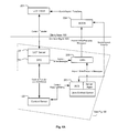
- FIG. 16 is a flow chart illustrating a process for dynamic provisioning of server resources using the dormant state.
- the dormant state is useful to provide flexibility to the system. For example, in the cloud-based environment, the ability to scale up or scale down to adjust and balance for system load requirements on-demand is critical. The use of the dormant state provides a simple tool to scale down a server deployment. Likewise, the dormant state may be used as a tool for load balancing.
- FIG. 1 is a simplified block diagram of a distributed computer network 10 .
- Computer network 10 includes a number of client systems 11 , 12 , 13 coupled to a server system 20 via a communication network 5 .
- Each of the client systems 11 , 12 , 13 and the server system 20 are coupled to the communication network 5 by communication links 6 , 7 , 8 , 9 , respectively.
- Communication network 5 provides a mechanism for allowing the various components of distributed network 10 to communicate and exchange information with each other.
- Communication network 5 may include many interconnected computer systems and communication links.
- Communication links 6 , 7 , 8 , 9 may be hardwire links, optical links, satellite or other wireless communications links, wave propagation links, or any other mechanisms for communication of information, and may be the same or different for the various hardware components that are coupled to the network 5 .
- Various communication protocols may be used to facilitate communication between the various systems shown in FIG. 1 , including TCP/IP, HTTP protocols, wireless application protocol (WAP), vendor-specific protocols, customized protocols and others.
- communication network 5 is the Internet, while in other embodiments, any suitable communication network may be used including a local area network (LAN), a wide area network (WAN), a wireless network, an intranet, a private network, a public network, a switched network, any combinations of these, and the like.
- LAN local area network
- WAN wide area network
- wireless network an intranet
- private network a private network
- public network a public network
- switched network any combinations of these, and the like.
- Distributed computer network 10 is merely one illustrative embodiment and is not intended to limit the scope of the disclosure.
- One of ordinary skill in the art would recognize many other variations, modifications and alternatives in how to effectively arrange such components and systems.
- one or more client systems may request information from the server system, which responds to the client by providing the requested information.
- a server system will typically have more computing and storage capacity than client systems, and indeed, the server system may be a gateway and content manager for providing access to content storage and related repository services as further described below.
- a particular computer system may act as either a client or a server depending on whether the computer system is requesting or providing information.
- aspects of the subject matter disclosed herein are described as using a client/server environment, it should be apparent that the subject matter may be embodied in other ways, for example, as a stand-alone computer system, or part of a cloud-computing environment.
- Server system 20 receives requests for information from one or more of client systems 11 , 12 , 13 and performs processing in order to satisfy the requests, then forwards the resultant information back to the requesting client system.
- the processing required to satisfy the request may be performed by server system 20 or may alternatively be delegated to or obtained with the help of other servers connected to communication network 5 or to server system 20 .
- Client systems 11 , 12 , 13 enable users to access and query information stored or managed by server system 20 .
- a web browser application executing on a client system enables users to select, access, retrieve and/or query information stored or managed by server system 20 .
- Examples of web browser programs include the Internet Explorer browser by Microsoft Corporation, the Firefox browser by Mozilla Foundation, and others.
- FIG. 2 shows an exemplary computer workstation 50 that may serve as either a client or server system, including a monitor 51 with display screen 52 , CPU cabinet 53 , keyboard 54 and mouse 55 having one or more selection buttons 56 .
- CPU cabinet 53 houses familiar computer components, such as mass storage devices 57 , and other internal components which are not shown, such as a processor, memory, and the like, as further described with reference to FIG. 3 below.
- Mass storage devices 57 may include disk drives, floppy disks, magnetic disks, optical disks, magneto-optical disks, fixed disks, hard disks, CD-ROMs, recordable CDs, DVDs, recordable DVDs (e.g., DVD-R, DVD+R, DVD-RW, DVD+RW, HD-DVD, or Blu-ray Disc), flash and other nonvolatile solid-state storage (e.g., USB flash drive), battery-backed-up volatile memory, tape storage, reader, and other similar media, and combinations of these.
- disk drives floppy disks, magnetic disks, optical disks, magneto-optical disks, fixed disks, hard disks, CD-ROMs, recordable CDs, DVDs, recordable DVDs (e.g., DVD-R, DVD+R, DVD-RW, DVD+RW, HD-DVD, or Blu-ray Disc), flash and other nonvolatile solid-state storage (e.g., USB flash drive), battery-backed-up volatile memory, tape
- a computer-readable medium may include any medium that participates in providing instructions to one or more processors for execution. Such a medium may take many forms including, but not limited to, nonvolatile, volatile, and transmission media.
- Nonvolatile media includes, for example, flash memory, or optical or magnetic disks.
- Volatile media includes static or dynamic memory, such as cache memory or RAM.
- Transmission media includes coaxial cables, copper wire, fiber optic lines, and wires arranged in a bus. Transmission media can also take the form of electromagnetic energy, radio frequency signals, acoustic or light waves, such as those generated during radio wave and infrared data communications.
- a binary machine-executable version of software instructions for providing the features described herein may be stored or reside in RAM or cache memory, or on mass storage device 57 .
- the source code of the software may also be stored or reside on mass storage device 57 (e.g., hard disk, magnetic disk, tape or CD-ROM).
- software code may be transmitted via wires or radio waves, or downloaded through a network such as the Internet.
- FIG. 3 A system block diagram of the computer system/workstation 50 is shown in FIG. 3 .
- the display monitor 51 , keyboard 54 and storage devices 57 are as shown in FIG. 2 .
- the CPU cabinet 53 contains key components such as central processor 61 , system memory 62 , input/output (I/O) controller 63 , display adapter 64 , serial or universal serial bus (USB) port 65 , network interface 66 , and speaker 67 .
- a computer system may include more or fewer components and/or subsystems.
- a computer system could include more than one processor (i.e., a multiprocessor system) or a system may include a cache memory.
- the system bus 70 of computer system 50 are exemplary of an interconnection scheme serving to link the subsystems.
- speaker 67 could be connected to the other subsystems through a port or have an internal direct connection to central processor 61 .
- the processor 61 may include multiple processors or a multi-core processor, which may permit parallel processing of information.
- Computer system 50 is only one example of a suitable computer system. Other configurations of components and/or subsystems suitable for use with the methods described herein will be readily apparent to one of ordinary skill in the art.
- Computer software products may be written in any of various suitable programming languages, such as C, C++, C#, Pascal, Fortran, Perl, Matlab (from MathWorks), SAS, SPSS, JavaScript, AJAX, Java, SQL, and XQuery.
- a computer software product may be an independent application with data input and data display modules.
- computer software products may be classes that are instantiated as distributed objects, or component software such as Java Beans or Enterprise Java Beans (both by Oracle Corporation).
- the subject matter described herein is embodied as a computer program product which stores instructions, such as computer code, that when executed by a computer cause the computer to perform the processes and/or techniques described below.
- the computer system 50 runs an operating system (OS) to manage hardware resources and provide common application services for application software.
- OS operating system
- the computer 50 may run a Microsoft Windows® operating system (e.g., Windows NT, Windows XP, Windows Vista, Windows 7, Windows CE, Windows Mobile), or Linux, UNIX, Sun OS, Solaris, Mac OS X, Alpha OS, AIX, IRIX32, or IRIX64.
- Microsoft Windows® operating system e.g., Windows NT, Windows XP, Windows Vista, Windows 7, Windows CE, Windows Mobile
- Linux e.g., NT, Windows XP, Windows Vista, Windows 7, Windows CE, Windows Mobile
- Linux e.g., UNIX, Sun OS, Solaris, Mac OS X, Alpha OS, AIX, IRIX32, or IRIX64.
- Other operating systems may also be used.
- FIG. 4 illustrates a more detailed embodiment of a distributed client/server system that provides an enterprise-level content management and repository service.
- a repository system 140 is operated and managed by a content management system 120 , which in turn provides access to the repository for client applications 100 .
- the client applications 100 originate from client devices, such as devices 101 , 102 , 103 , which communicate through a network 104 with an application server 121 in order to use one or more applications hosted on the application server.
- the network 104 is an Ethernet connection using conventional TCP/IP communication methods with both client devices and server devices.
- LAN local area network
- WAN wide area network
- SAN storage area network
- Client devices may be any type of processor-based digital device, such as desktop or laptop computer, iPhone® or other smart hand-held device, or other.
- the application server 121 hosts one or more applications running on a content management platform that provide access to repository 140 for clients hosted on content server 122 , which is also accessible to clients via network 104 .
- An HTTP server 123 is also coupled to the network 104 to provide an administrative terminal for system operators to perform system maintenance, logging, access control, etc., as further described below.
- the system operator may initiate a dormant state for server components to facilitate patches, upgrades, load balancing, and other useful operations as further described below.
- the repository 140 is provided for use by client applications 100 , through the content server 122 , which is accessible to the client devices through a network 104 .
- the repository 140 may include a file store 141 for storing content items, a relational database 142 for storing attributes/metadata associated with the content items, a full-text index store 143 for the content items, and directory services 144 .
- a software platform runs on each of the various components, such as the EMC Documentum Platform software and related EMC Enterprise Content Management software, distributed by EMC Corporation, Hopkington, Mass.
- the Documentum Platform provides capabilities for managing enterprise content and is the foundation for related content management and case management product offerings.
- FIG. 5 shows one simplified embodiment of the application server 121 , which runs a content management framework 150 having a foundation layer 151 , such as Documentum Foundation Classes (DFC), an interface layer 152 , such as Documentum Foundation Services (DFS), and one or more applications on application layer 153 having integrated Documentum functionality through a Web Development Kit (WDK) or Webtop, for example.
- the HTTP server 123 runs a similar content management framework, for applications such as System Administrator or Intranet Client.
- DFC is the programming interface for accessing the functionality of the Documentum platform through Java and COM class libraries and underlies all Documentum platforms.
- DFS is an SOA development framework and application programming interface (API), based on web services, and designed to support interoperable machine-to-machine interaction over a network.
- API application programming interface
- the Documentum platform also includes an extensible Business Objects Framework (BOF) which is built into DFC.
- BOF provides a useful framework and methodology for developing reusable business logic components called Business Objects that can be plugged into middle tier or client applications. More information about the Documentum Platform and related content management and case management product offerings can be found on the EMC website located at URL www.emc.com.
- FIG. 6A is a simplified diagram of the relevant Documentum components that work together in one embodiment to implement content transfer sessions.
- Documentum provides a utility called Unified Client Facilities (UCF) that is used to transfer content between servers and clients.
- UCF client component 201 runs as a Java applet on a client machine.
- a UCF server component 202 runs on the application server 121 , with integrated DFC 151 of the content management framework.
- One route for content transfer to and from the repository is through the content server 122 , the UCF Server 202 and the UCF client 201 .
- a faster route for content transfers is through an Accelerated Content Server (ACS) 203 .
- ACS 203 is installed with each content server installation (including primary content server CS and remote content server RCS) and provides direct access to content on the content server machine 122 for synchronous or asynchronous transfer to a local cache 204 .
- ACS is installed as a web application in the embedded application server as part of each content server, and is run as a Java Method Server.
- the local cache 204 is called a Branch Office Caching Server (BOCS) in the Documentum platform, and is a light-weight cache server 203 that allows remote users to read and write content from/to local servers.
- the Documentum Messaging Server 205 receives and delivers messages between applications, such as requests for action from DFC 151 on the application server to the BOCS 203 .
- FIG. 6B is a portion of FIG. 6A showing how a connection broker 206 may be used as an intermediary between the content server 122 , the ACS 205 , and the DFC 151 .
- FIG. 6C is a simplified version of FIG. 6B .
- the connection broker 206 is a name server for the Documentum content server. When a connect method is issued, the request goes to the connection broker identified in an initialization file (dmcl.ini) in the client device.
- the connection broker provides a list of active content servers in return to the application server/DFC 151 , and the DFC establishes a session with one of the active servers.
- connection broker 206 does not request information from the content server 122 , but relies on the server to regularly broadcast or project its status/connection information to the connection broker. This feature, i.e., which connection broker to project to, is set in the configuration file (config.ini) on each server.
- server components may be configured with a “dormant” state of operation wherein no new connections with clients are accepted, and existing connections/sessions are made read-only. Any pending transactions in existing sessions are preferably completed prior to moving to read-only status.
- a server is in the dormant state, its status at the connection broker will be updated, and the connection broker will notify end users that new connections can be made to that server.
- the dormant state will be invoked through program instructions executed in relevant computer-implemented components, for example, using a remote procedure call (RPC) in the server, and application programming interfaces (APIs) in other components having DFC and DFS frameworks. Examples of such instructions are included in the Appendix below. Instructions should also include status checks to see whether the selected components are in the dormant state or not.
- RPC remote procedure call
- APIs application programming interfaces
- the dormant server state may be useful to help avoid overloading issues. For example, a server that appears to be failing or becoming overloaded may be moved to a dormant state so that it can avoid processing new tasks and simply complete processing of its existing load if possible. The server may then be taken offline for evaluation, upgrade, repair or replacement as necessary.
- the dormant state may be used to provide system flexibility, for example, by being part of a scheme to balance loads across a system of multiple servers, or to allocate the deployment of resources dynamically in a multiple server system.
- the dormant state may also be useful to make component and/or system upgrades, such as a software patch, service pack, minor release, or major release.
- the dormant state facilitates performing upgrades in a multiple server system by moving one server at a time to the dormant state, upgrading the server, then returning the server to active service.
- the dormant state can only be set or reset by members of a privileged access group.
- a group called Data Center Managers dm_datacenter_managers
- dm_datacenter_managers can be established and maintained by a superuser and/or group administrator to use and administer a server or server cluster resource with among other things, the techniques described herein.
- the dormant state may be implemented in a server through the process 300 shown in FIG. 7A .
- a request to change state to a dormant mode is received by the server, for example, as sent by a user, such as Data Center Manager.
- the authorization of the user making the request is tested. If the user is not authorized for this operation, i.e., a member of the Data Center Managers group, then an error is generated in step 303 . If the user is authorized in step 302 , then the server proceeds to process the state change request in step 304 , as further illustrated in FIG. 7B . When the processing associated with the state change request is complete, the server waits in step 305 to be placed back into active service.
- step 310 the server is configured to not accept any new connections from regular users (but see exception for privileged users below).
- the server checks in step 311 to see if there are any existing connections. If not, then in step 312 the server is changed to a read-only state, and other system components are notified accordingly as necessary in step 320 . If there are existing connections, then in step 313 , the server checks to see if there are open transactions pending for these sessions. If not, then the server moves to the read-only state in step 312 . If there are open transactions in the existing connections in step 313 , then those transactions are allowed to commit or abort in step 314 , before the server is moved to the read-only state in step 312 .
- the objectives of the dormant state for a content server are largely met by prohibiting new connections to the server and by allowing server content to be accessed in a read-only mode.
- an exception to the prohibition against new connections may be provided for the privileged user group to allow them to connect and perform regular content server and repository transactions as well as administrative tasks.
- these privileged users want to perform update operations, they need to explicitly enable that feature in the configuration object.
- the elements of the repository can also be made read-only through the content server—no changes can be made to content in the file system, to metadata in the database, or to the repository index.
- the job agent which normally schedules and processes jobs for the server, is prohibited from processing jobs, and methods are prohibited from launching through the Java Method Server by not sending any HTTP post instructions.
- other components may need to be made dormant, or at least have their behaviors defined for the times when one or more content servers is dormant.
- the ACS associated with that content server should also be moved to a dormant state.
- the dormant status of the ACS should be persisted, for example, in the ACS configuration object.
- no new read or write operations for content are allowed.
- connection broker may also be set to a dormant state, and that status persisted.
- the connection broker When dormant, the connection broker will not send a server map in response to a client request, and may stop receiving status projections from other components (like content server and ACS).
- Instructions to set the dormant state and check the dormant status of the connection broker are implemented as APIs, which will be used by the DFS to check if it can pull information from the connection broker, and by the ACS to see if it can project information to the connection broker.
- the Java Method Server will generally not be moved to a dormant state, largely because some instances of the JMS can be shared by multiple servers. This can be readily handled by having the server in its dormant state not post method execution requests to the JMS. If all servers using a particular JMS become dormant, then the JMS will simply have no methods to execute.
- FIG. 8A illustrates a method 320 implemented in the content server for using the dormant state in a content server deployment.
- a request for a status change is received from the Data Center Manager in step 321 .
- the status change to dormant for the content server is initiated in step 322 (for example, as described with reference to FIGS. 7A-7B above);
- a request to make a status change to dormant is sent to the ACS in step 323 ; and
- posts to the Java method server are stopped in step 324 .
- the content server projects its changed status to the connection broker in step 325 .
- the ACS will also project its status change to the connection broker upon entering the dormant state.
- FIGS. 8B and 8C These steps are more clearly illustrated in the sequence diagram for a state change in the content server and related components shown in FIGS. 8B and 8C .
- these changes may be implemented through suitable instructions formed in remote procedure calls (RPCs) in the content server and application programming interfaces (APIs) in the other components, examples of which are provided in the Appendix below.
- RPCs remote procedure calls
- APIs application programming interfaces
- FIG. 8B a Data Center Manager with suitable privileges makes a request for the state change, typically through a client device or admin terminal located internally to the content management system 120 , for example at the HTTP server 123 (rather than externally through the client application layer 100 ). The request is sent to the DFC layer in step 401 .
- the state change request triggers a RPC in the content server to “requestDormancy” in step 402 .
- the content server registers the state change request.
- the result (success or failure) is reported backed to the DFC, which likewise reports back to the Data Center Manager in step 405 .
- Step 408 is a loop run in the ACS that checks for any state change requests from the content server, e.g. in step 407 .
- a state change request is received by the ACS, it changes state in step 409 , then either stops processing requests if changed to dormant state, or allows requests if changed to active state, in step 410 .
- the status change is then projected to the connection broker in step 411 .
- the content server waits for current sessions to either commit or abort. For example, the content server waits for open data collections to close (step 421 ); stops all post requests to the Java Method Server (step 422 ); waits for all open transactions to close (step 423 ); and makes any current sessions read-only (step 424 ).
- step 425 the content server is moved to the requested state. If the requested state is the active state, then after the ACS changes state, the content server is moved to the active state. If the requested state is the dormant state, then after current sessions are committed or aborted, the content server is moved to the dormant state.
- FIG. 9A illustrates a method 330 implemented in the content server or connection broker for using the dormant state in a multi-server (server cluster) deployment.
- a request from the Data Center Manager is received in step 331 , but note this request specifies “all servers.”
- three steps occur: (i) the status in the configuration object for the server cluster is changed in step 332 ; (ii) a counter is incremented in the change record in step 333 ; and (iii) a process thread is used to invoke status changes for all servers in step 334 .
- “Change Checker” is a simple thread or process that wakes up periodically to look for changes from other servers and refresh the changes to its server instances.
- a Data Center Manager requests a state change, which is sent to the DFC layer in step 451 .
- the state change request triggers a RPC in the repository server to “requestDormancyforRepository” in step 452 .
- the repository server marks the state change request, and in step 454 , the changed record count is incremented.
- FIG. 10A illustrates a method 340 implemented in the content server or connection broker for checking the dormant status of a single server or multi-server deployment.
- the status request from the Data Center Manager is received in step 341 . If a single server deployment in step 342 , then the process checks and interprets values stored in server memory. If not a single server deployment in step 342 , then it is a multi-server deployment, and the process 340 checks and interprets values stored in the configuration object for the server cluster.
- FIGS. 10B and 10C Related sequence diagrams for checking the status of a single content server and a multi-server cluster are shown in FIGS. 10B and 10C , respectively.
- the Data Center Manager requests a status check on the dormant status for the repository in step 471 , which causes the DFC to trigger a RPC in the content server to “checkDormantStatus” in step 472 .
- the content server runs a routine to identify the non-persistent state of the server in step 473 , and returns that result to the DFC in step 474 , which in turn delivers the result to the Data Center Manager in step 475 .
- FIG. 10B the Data Center Manager requests a status check on the dormant status for the repository in step 471 , which causes the DFC to trigger a RPC in the content server to “checkDormantStatus” in step 472 .
- the content server runs a routine to identify the non-persistent state of the server in step 473 , and
- the Data Center Manager requests a status check on the dormant status of the repository server in step 481 , which causes the DFC to trigger a RPC in the repository server to “checkRepositoryStatus” in step 482 .
- the repository server retrieves the state of the server from its configuration file in step 483 , returns the status to the DFC in step 484 , which delivers the result to the Data Center Manager in step 485 .
- the application server seeks to create a new session on behalf of a client device, and thus contacts the connection broker (connection 511 ) to refresh the current active server map.
- the connection broker provides a list of active servers back to the application server (connection 512 ).
- the DFC then establishes a session with one of the active servers through one of the connections 513 , 514 or 515 .
- the selected content server can be maintained, upgraded or replaced as necessary while in the dormant state, and then returned to active service only when appropriate.
- a server count x is initialized in step 501 , e.g. set equal to one. Other selection or indexing criteria could be used by the Data Center Manager to pick and choose servers.
- the Data Center Manager requests that the selected server be set to the dormant state. Before setting the server to the dormant state, however, the server checks to see if all pending sessions have been committed or aborted in step 503 . If not, then the process waits for a predefined interval (step 504 ), which is set in the configuration file for the server, and checks again in step 503 .
- step 505 When all pending sessions have been committed or aborted in the check of step 503 , then the server is set to the dormant state in step 505 . As described above, the server will not allow any new connections while in the dormant state.
- the Data Center Manager makes changes in step 506 , for example, software upgrades, patches, service packs and releases, which may include shutting down the server before loading the new software.
- the server After loading the new software, the server is restarted in step 507 with a new binary dump.
- the server count is incremented n step 508 , and if the server count has not reached the maximum, then the process returns to step 502 to perform the upgrade on the next server. If the server count has reached its maximum, the process ends in step 510 .
- FIGS. 13A-13B An example of a service pack upgrade is illustrated in FIGS. 13A-13B .
- the production system 535 is placed into the dormant mode, as shown by the dashed box. Further, the production system operates on read-only snapshot 536 of the file system taken at a discrete point-in-time.
- FIG. 13B a writable copy 537 of the snapshot is created, and upgrades 538 are performed directly on the file system in the snapshot copy. If the upgrade is successful, then users are moved to the upgraded copy of the production system 539 .
- a process 520 for providing the service pack upgrade is illustrated in FIG. 14 .
- Many servers regularly take a point-in-time snapshot image of the file systems, and in step 521 , the Data Center Manager obtains a current point-in-time snapshot of the file system.
- the Data Center Manager requests that all servers in the file system be moved to the dormant state, and in step 523 , that the file system be operated on a read-only basis on the snapshot copy of the file system.
- step 524 a writeable copy is created from the point-in-time snapshot, which is used to perform the upgrade in step 525 . If the upgrade is successful (step 526 ), then the servers are returned to the active state based on the upgraded copy (step 527 ), and all users are moved to the upgraded copy (step 528 ). The read-only snapshot is discarded in step 529 and the process is done.
- step 526 If the upgrade was unsuccessful in step 526 , then the writable snapshot is discarded (step 530 ), the point-in-time snapshot is placed into a writable mode (step 531 ), and the servers are returned to the active state based on the writable point-in-time snapshot copy (step 532 ).
- connection broker By setting one or more servers into a dormant mode, the connection broker can redistribute loads to other active servers. This would force reduced loading before it becomes problematic.
- a simple process 540 is shown in FIG. 15A .
- a load threshold is set.
- each of the server loads in the cluster is monitored, for example, by a user in the Data Center Manager group, or with a monitoring software routine in the server itself.
- monitored server loads are periodically compared to the threshold. If no server loads exceed the threshold (step 544 ), then the process continues to monitor in step 542 and periodically make comparisons in step 543 . If a server load does exceed the threshold in step 544 , then that server is handled by a load balancing module in step 545 , and the process returns to the monitoring step.
- step 546 the overloaded server is placed into the dormant state. At this point, no new connections are accepted from client/users, and the server status is projected to the connection broker, i.e., changed state to dormant.
- step 547 pending transactions on existing connections are continued until complete or the server load has fallen to within acceptable limits.
- Step 548 checks to see if all pending transactions are complete. If not, return to step 547 . If so, the server is returned to the active state in step 549 .
- machine resources such as shared memory, CPU usage, file handles
- Resources of the content server may also be monitored and evaluated, such as internal cache usage; response time for each RPC or each user transaction; size of database tables; configuration settings for workflow agents; database usage; and file system usage.
- Activity response times may be recorded and stored in shared memory; or this information may be obtained through a query from DFC.
- Global cache and session cache are monitored for cache consumption.
- the content server and other components provide an interface to return performance metrics data so that it may be aggregated and analyzed.
- a service may be called or run to collect relevant information.
- server deployments need to be scaled up or down to meet load requirements.
- Using the dormant mode can be an effective method of scaling down a deployment. Scaling up is simply a matter of adding another server to the server cluster.
- FIG. 16 shows a simple process 560 for scaling up or scaling down a server deployment.
- the connection broker maintains information about ongoing load requirements and available server capacity.
- the connection broker distributes loads equally across all servers in the cluster.
- the connection broker periodically evaluates the load requirements, and in step 563 , considers whether more capacity is needed, based upon collected metrics. If so, then one or more servers is added to the cluster in step 564 .
- the connection broker is updated in step 565 , then returns to maintain and distribute loads in steps 561 and 562 . If more capacity was not called for in step 563 , then the question of whether less capacity is needed, based upon collected metrics, in considered in step 566 .
- the process returns to maintain and distribute loads in steps 561 and 562 . If so, then one or more servers is moved to a dormant state in step 567 , then the connection broker is updated in step 565 , and returns to maintain and distribute loads in steps 561 and 562 . Any of the dormant state techniques previously described could be incorporated.
- a status indicator called “DormantStatus” is provided to enumerate the present state for the relevant server or repository, and has the state values of ACTIVE (1), DORMANT (2), or DORMANCY_REQUESTED (3).
- This instruction initiates a request to change the state of the server to which a session is connected to the dormant state.
- the dormant state is not persistent and the server will become active by default upon a restart or re-initialization.
- the requestDormancy instruction will return a True result if the request succeeds, False if not, and will throw a DfException if an error occurs.
- This instruction checks the status of the server to which this session is connected, and returns DormantStatus as an enumeration representing the status of the requested entity.
- a value of “ACTIVE” means the entity is active; a value of “DORMANCY_REQUESTED” means that the entity has submitted a request to become dormant; and a value of “DORMANT” means the entity is dormant.
- the instruction will throw a “DfException” if an error occurs while requesting status.
- This instruction sends a request to move the server to which this session is connected to an active state.
- the instruction will return “True” if the request succeeds, “False” if not; and will throw a DfException if an error occurs while requesting dormancy.
- This instruction sends a request to move the repository or server to a dormant state.
- allServersForThisRepository When the parameter “allServersForThisRepository” is True, dormancy is requested for this repository. This state is persistent for the repository and will have to be explicitly made active. When false, dormancy is requested only for the server through which this session is connected. The instruction will return True if the request succeeds, False if not, and throws a DfException if an error occurs while requesting dormancy.
- This instruction checks to see whether a server or repository is dormant or not. When the parameter “allServersForThisRepository” is true, a status check is requested for this repository. When false, a status check is requested only for the server through which this session is connected.
- the instruction will return a “DormantStatus” enumeration representing the status of the requested entity: ACTIVE means that the entity is active, DORMANCY_REQUESTED means that the entity has submitted a request to become dormant, DORMANT means the entity is dormant.
- the instruction will throw a DfException if an error occurs while requesting status.
- This instruction sends a request to move the repository or server to an active state.
- the parameter “allServersForThisRepository” is True, the request is to make the entire repository active.
- the request is to make only the server to which this session is connected active.
- the instruction will return True if the request succeeds, False otherwise, and throws a “DfException” if an error occurs while requesting dormancy.
- This instruction disables save operation for the dormant state.
- a privileged user from the (dm_datacenter_managers) group has enabled the save operation, it can be disabled back again after performing necessary operation in the dormant state.
- This method allows the user of this session to disable save operations. The method will return True if the save was disabled for the user of this session, False otherwise, and throws a “DfException” if an error occurs while disabling save.
- This instruction only projects to the connection broker that this server is dormant. The server could actually be active. After calling this method, no new connections are made to that server. It will have no impact on existing connections or activities that do not require a new connection. The instruction will return True if projection to connection broker was successful, False otherwise, and throws a “DfException” if an error occurs while projecting dormant status to connection broker.
- a generic RPC called “DATACENTER_OPERATION” is provided to support all datacenter related operations of which dormancy is one. The following are the dormancy-related datacenter operations and parameters:
- the CHECK_DORMANCY operation is different from other operations because it can be run by any user in the repository, instead of being restricted to only privileged users like the Data Center Managers group.
- This flag indicates whether dormancy needs to be applied to all servers serving a repository or just to the server that is connected for the current session;
- This parameter reflects the state to which this server/repository is being moved. This parameter is meaningful only when the value for DATACENTER_OPERATION is REQUEST_DORMANCY. Valid values are: ACTIVE—state change is going back to the normal state; or DORMANT—state change is going back to the dormant state.
- This flag indicates to the server that it should only project its status, i.e., dormant or active, to the connection broker. This is used primarily when the server sees its load increasing and wants to reduce the load. For example, if the OPERATION is REQUEST_DORMANCY, and the REQUEST_STATE is DORMANT, then if PROJECTION_ONLY is set to TRUE, then the server will project its status to the connection broker as dormant even though it is actually active. However, if the OPERATION is REQUEST_DORMANCY, and the REQUEST_STATE is ACTIVE, then if PROJECTION_ONLY is set to TRUE, then the server will project its status to the connection broker as active.
- the server may be active, but had previously informed the connection broker it was dormant. If the server is dormant and the PROJECTION_ONLY flag is set to true while making the server active, it will throw an error. Also, marking a server as dormant with this flag set to true should stop the server projection to the connection broker, until it is explicitly called to make the server active.
- RESULT is an attribute that will be set when either REQUEST_DORMANCY or CHECK_DORMANCY is executed, and provides more detail regarding the operation. If RESULT is False, then this attribute could contain an error messaging with the details of the failure. If RESULT is True, then this attribute could have the following values: ACTIVE, DORMANCY_REQUESTED, or DORMANCY.
Abstract
Description
Claims (20)
Priority Applications (1)
| Application Number | Priority Date | Filing Date | Title |
|---|---|---|---|
| US13/433,574 US9319274B1 (en) | 2012-03-29 | 2012-03-29 | Method and system for dynamic provisioning using server dormant mode for virtual server dormancy |
Applications Claiming Priority (1)
| Application Number | Priority Date | Filing Date | Title |
|---|---|---|---|
| US13/433,574 US9319274B1 (en) | 2012-03-29 | 2012-03-29 | Method and system for dynamic provisioning using server dormant mode for virtual server dormancy |
Publications (1)
| Publication Number | Publication Date |
|---|---|
| US9319274B1 true US9319274B1 (en) | 2016-04-19 |
Family
ID=55700142
Family Applications (1)
| Application Number | Title | Priority Date | Filing Date |
|---|---|---|---|
| US13/433,574 Active 2032-09-14 US9319274B1 (en) | 2012-03-29 | 2012-03-29 | Method and system for dynamic provisioning using server dormant mode for virtual server dormancy |
Country Status (1)
| Country | Link |
|---|---|
| US (1) | US9319274B1 (en) |
Cited By (5)
| Publication number | Priority date | Publication date | Assignee | Title |
|---|---|---|---|---|
| US20150178137A1 (en) * | 2013-12-23 | 2015-06-25 | Microsoft Corporation | Dynamic system availability management |
| US20160026481A1 (en) * | 2013-03-21 | 2016-01-28 | Storone Ltd. | System and method for deploying a data-path-related plug-in for a logical storage entity of storage system |
| US20160197850A1 (en) * | 2015-01-04 | 2016-07-07 | Emc Corporation | Performing cross-layer orchestration of resources in data center having multi-layer architecture |
| US9652263B2 (en) * | 2015-06-15 | 2017-05-16 | International Business Machines Corporation | Migrating servers into a secured environment |
| CN109062761A (en) * | 2018-07-26 | 2018-12-21 | 郑州云海信息技术有限公司 | A kind of server state management method, apparatus and system |
Citations (44)
| Publication number | Priority date | Publication date | Assignee | Title |
|---|---|---|---|---|
| US5819292A (en) * | 1993-06-03 | 1998-10-06 | Network Appliance, Inc. | Method for maintaining consistent states of a file system and for creating user-accessible read-only copies of a file system |
| US6141759A (en) * | 1997-12-10 | 2000-10-31 | Bmc Software, Inc. | System and architecture for distributing, monitoring, and managing information requests on a computer network |
| US6226667B1 (en) * | 1998-05-26 | 2001-05-01 | International Business Machines Corporation | Method and apparatus for preloading data in a distributed data processing system |
| US20020194015A1 (en) * | 2001-05-29 | 2002-12-19 | Incepto Ltd. | Distributed database clustering using asynchronous transactional replication |
| US20030158940A1 (en) * | 2002-02-20 | 2003-08-21 | Leigh Kevin B. | Method for integrated load balancing among peer servers |
| US20040111508A1 (en) * | 2002-12-10 | 2004-06-10 | International Business Machines Corporation | Apparatus and methods for co-location and offloading of web site traffic based on traffic pattern recognition |
| US20040210796A1 (en) * | 2001-11-19 | 2004-10-21 | Kenneth Largman | Computer system capable of supporting a plurality of independent computing environments |
| US6877016B1 (en) * | 2001-09-13 | 2005-04-05 | Unisys Corporation | Method of capturing a physically consistent mirrored snapshot of an online database |
| US20050188252A1 (en) * | 2004-02-25 | 2005-08-25 | Hitachi, Ltd. | Data storage systems and methods |
| US20050193245A1 (en) * | 2004-02-04 | 2005-09-01 | Hayden John M. | Internet protocol based disaster recovery of a server |
| US20050234931A1 (en) * | 2004-04-06 | 2005-10-20 | Microsoft Corporation | Managing client configuration data |
| US20060130040A1 (en) * | 2004-11-30 | 2006-06-15 | Oracle International Corporation | Patch Impact analyzer |
| US20060212481A1 (en) * | 2005-03-21 | 2006-09-21 | Stacey Christopher H | Distributed open writable snapshot copy facility using file migration policies |
| US20060212350A1 (en) * | 2005-03-07 | 2006-09-21 | Ellis John R | Enhanced online advertising system |
| US20070006214A1 (en) * | 2005-06-20 | 2007-01-04 | Dubal Scott P | Updating machines while disconnected from an update source |
| US7200626B1 (en) * | 2004-01-22 | 2007-04-03 | Unisys Corporation | System and method for verification of a quiesced database copy |
| US7373644B2 (en) * | 2001-10-02 | 2008-05-13 | Level 3 Communications, Llc | Automated server replication |
| US20080148083A1 (en) * | 2006-12-15 | 2008-06-19 | Microchip Technology Incorporated | Direct Memory Access Controller |
| US7441135B1 (en) * | 2008-01-14 | 2008-10-21 | International Business Machines Corporation | Adaptive dynamic buffering system for power management in server clusters |
| US20090006884A1 (en) * | 2007-06-29 | 2009-01-01 | Microsoft Corporation | Automatically managing system downtime in a computer network |
| US20090077367A1 (en) * | 2007-09-14 | 2009-03-19 | International Business Machines Corporation | Managing reboot operations |
| US20090177684A1 (en) * | 2008-01-07 | 2009-07-09 | International Business Machines Corporation | Automated configuration updater |
| US7590660B1 (en) * | 2006-03-21 | 2009-09-15 | Network Appliance, Inc. | Method and system for efficient database cloning |
| US20100058093A1 (en) * | 2008-09-02 | 2010-03-04 | Computer Associates Think, Inc. | System and Method for Energy and Assets Saving and for Improving Ownership and Sustainability Awareness |
| US20100088281A1 (en) * | 2008-10-08 | 2010-04-08 | Volker Driesen | Zero Downtime Maintenance Using A Mirror Approach |
| US20100106990A1 (en) * | 2008-10-27 | 2010-04-29 | Netapp, Inc. | Power savings using dynamic storage cluster membership |
| US7739388B2 (en) * | 2007-05-30 | 2010-06-15 | International Business Machines Corporation | Method and system for managing data center power usage based on service commitments |
| US20100218005A1 (en) * | 2009-02-23 | 2010-08-26 | Microsoft Corporation | Energy-aware server management |
| US20100257140A1 (en) * | 2009-03-31 | 2010-10-07 | Philip John Davis | Data archiving and retrieval system |
| US7823145B1 (en) * | 2006-03-31 | 2010-10-26 | Vmware, Inc. | Updating software on dormant disks |
| US7870241B2 (en) * | 2002-11-27 | 2011-01-11 | International Business Machines Corporation | Automated power control policies based on application-specific redundancy characteristics |
| US20110082835A1 (en) * | 2009-10-02 | 2011-04-07 | Symantec Corporation | Periodic file system checkpoint manager |
| US20110087912A1 (en) * | 2009-10-08 | 2011-04-14 | Bridgette, Inc. Dba Cutting Edge Networked Storage | Power saving archive system |
| US20110106949A1 (en) * | 2009-10-30 | 2011-05-05 | Cisco Technology, Inc. | Balancing Server Load According To Availability Of Physical Resources |
| US20110161957A1 (en) * | 2009-12-31 | 2011-06-30 | Microsoft Corporation | Virtualized Eco-Friendly Remote Presentation Session Role |
| US8046694B1 (en) * | 2007-08-06 | 2011-10-25 | Gogrid, LLC | Multi-server control panel |
| US20110265076A1 (en) * | 2010-04-21 | 2011-10-27 | Computer Associates Think, Inc. | System and Method for Updating an Offline Virtual Machine |
| US20120110142A1 (en) * | 2010-10-29 | 2012-05-03 | Bank Of America Corporation | Configuration management utility |
| US8181046B2 (en) * | 2008-10-29 | 2012-05-15 | Sandisk Il Ltd. | Transparent self-hibernation of non-volatile memory system |
| US8230249B2 (en) * | 2009-07-15 | 2012-07-24 | International Business Machines Corporation | Dynamic selection of server states for servers in a cluster of servers |
| US8261116B2 (en) * | 2006-12-07 | 2012-09-04 | Juniper Networks, Inc. | Distribution of network communications based on server power consumption |
| US8453214B1 (en) * | 2010-10-25 | 2013-05-28 | Go Daddy Operating Company, LLC | Methods of locking a website |
| US20130166943A1 (en) * | 2011-12-22 | 2013-06-27 | Alcatel-Lucent Usa Inc. | Method And Apparatus For Energy Efficient Distributed And Elastic Load Balancing |
| US8522228B1 (en) * | 2006-03-31 | 2013-08-27 | Vmware, Inc. | Updating software on dormant disks |
-
2012
- 2012-03-29 US US13/433,574 patent/US9319274B1/en active Active
Patent Citations (45)
| Publication number | Priority date | Publication date | Assignee | Title |
|---|---|---|---|---|
| US5819292A (en) * | 1993-06-03 | 1998-10-06 | Network Appliance, Inc. | Method for maintaining consistent states of a file system and for creating user-accessible read-only copies of a file system |
| US6141759A (en) * | 1997-12-10 | 2000-10-31 | Bmc Software, Inc. | System and architecture for distributing, monitoring, and managing information requests on a computer network |
| US6226667B1 (en) * | 1998-05-26 | 2001-05-01 | International Business Machines Corporation | Method and apparatus for preloading data in a distributed data processing system |
| US20020194015A1 (en) * | 2001-05-29 | 2002-12-19 | Incepto Ltd. | Distributed database clustering using asynchronous transactional replication |
| US6877016B1 (en) * | 2001-09-13 | 2005-04-05 | Unisys Corporation | Method of capturing a physically consistent mirrored snapshot of an online database |
| US7373644B2 (en) * | 2001-10-02 | 2008-05-13 | Level 3 Communications, Llc | Automated server replication |
| US20040210796A1 (en) * | 2001-11-19 | 2004-10-21 | Kenneth Largman | Computer system capable of supporting a plurality of independent computing environments |
| US20030158940A1 (en) * | 2002-02-20 | 2003-08-21 | Leigh Kevin B. | Method for integrated load balancing among peer servers |
| US7284067B2 (en) * | 2002-02-20 | 2007-10-16 | Hewlett-Packard Development Company, L.P. | Method for integrated load balancing among peer servers |
| US7870241B2 (en) * | 2002-11-27 | 2011-01-11 | International Business Machines Corporation | Automated power control policies based on application-specific redundancy characteristics |
| US20040111508A1 (en) * | 2002-12-10 | 2004-06-10 | International Business Machines Corporation | Apparatus and methods for co-location and offloading of web site traffic based on traffic pattern recognition |
| US7200626B1 (en) * | 2004-01-22 | 2007-04-03 | Unisys Corporation | System and method for verification of a quiesced database copy |
| US20050193245A1 (en) * | 2004-02-04 | 2005-09-01 | Hayden John M. | Internet protocol based disaster recovery of a server |
| US20050188252A1 (en) * | 2004-02-25 | 2005-08-25 | Hitachi, Ltd. | Data storage systems and methods |
| US20050234931A1 (en) * | 2004-04-06 | 2005-10-20 | Microsoft Corporation | Managing client configuration data |
| US20060130040A1 (en) * | 2004-11-30 | 2006-06-15 | Oracle International Corporation | Patch Impact analyzer |
| US20060212350A1 (en) * | 2005-03-07 | 2006-09-21 | Ellis John R | Enhanced online advertising system |
| US20060212481A1 (en) * | 2005-03-21 | 2006-09-21 | Stacey Christopher H | Distributed open writable snapshot copy facility using file migration policies |
| US20070006214A1 (en) * | 2005-06-20 | 2007-01-04 | Dubal Scott P | Updating machines while disconnected from an update source |
| US7590660B1 (en) * | 2006-03-21 | 2009-09-15 | Network Appliance, Inc. | Method and system for efficient database cloning |
| US8522228B1 (en) * | 2006-03-31 | 2013-08-27 | Vmware, Inc. | Updating software on dormant disks |
| US7823145B1 (en) * | 2006-03-31 | 2010-10-26 | Vmware, Inc. | Updating software on dormant disks |
| US8261116B2 (en) * | 2006-12-07 | 2012-09-04 | Juniper Networks, Inc. | Distribution of network communications based on server power consumption |
| US20080148083A1 (en) * | 2006-12-15 | 2008-06-19 | Microchip Technology Incorporated | Direct Memory Access Controller |
| US7739388B2 (en) * | 2007-05-30 | 2010-06-15 | International Business Machines Corporation | Method and system for managing data center power usage based on service commitments |
| US20090006884A1 (en) * | 2007-06-29 | 2009-01-01 | Microsoft Corporation | Automatically managing system downtime in a computer network |
| US8046694B1 (en) * | 2007-08-06 | 2011-10-25 | Gogrid, LLC | Multi-server control panel |
| US20090077367A1 (en) * | 2007-09-14 | 2009-03-19 | International Business Machines Corporation | Managing reboot operations |
| US20090177684A1 (en) * | 2008-01-07 | 2009-07-09 | International Business Machines Corporation | Automated configuration updater |
| US7441135B1 (en) * | 2008-01-14 | 2008-10-21 | International Business Machines Corporation | Adaptive dynamic buffering system for power management in server clusters |
| US20100058093A1 (en) * | 2008-09-02 | 2010-03-04 | Computer Associates Think, Inc. | System and Method for Energy and Assets Saving and for Improving Ownership and Sustainability Awareness |
| US20100088281A1 (en) * | 2008-10-08 | 2010-04-08 | Volker Driesen | Zero Downtime Maintenance Using A Mirror Approach |
| US20100106990A1 (en) * | 2008-10-27 | 2010-04-29 | Netapp, Inc. | Power savings using dynamic storage cluster membership |
| US8181046B2 (en) * | 2008-10-29 | 2012-05-15 | Sandisk Il Ltd. | Transparent self-hibernation of non-volatile memory system |
| US20100218005A1 (en) * | 2009-02-23 | 2010-08-26 | Microsoft Corporation | Energy-aware server management |
| US20100257140A1 (en) * | 2009-03-31 | 2010-10-07 | Philip John Davis | Data archiving and retrieval system |
| US8230249B2 (en) * | 2009-07-15 | 2012-07-24 | International Business Machines Corporation | Dynamic selection of server states for servers in a cluster of servers |
| US20110082835A1 (en) * | 2009-10-02 | 2011-04-07 | Symantec Corporation | Periodic file system checkpoint manager |
| US20110087912A1 (en) * | 2009-10-08 | 2011-04-14 | Bridgette, Inc. Dba Cutting Edge Networked Storage | Power saving archive system |
| US20110106949A1 (en) * | 2009-10-30 | 2011-05-05 | Cisco Technology, Inc. | Balancing Server Load According To Availability Of Physical Resources |
| US20110161957A1 (en) * | 2009-12-31 | 2011-06-30 | Microsoft Corporation | Virtualized Eco-Friendly Remote Presentation Session Role |
| US20110265076A1 (en) * | 2010-04-21 | 2011-10-27 | Computer Associates Think, Inc. | System and Method for Updating an Offline Virtual Machine |
| US8453214B1 (en) * | 2010-10-25 | 2013-05-28 | Go Daddy Operating Company, LLC | Methods of locking a website |
| US20120110142A1 (en) * | 2010-10-29 | 2012-05-03 | Bank Of America Corporation | Configuration management utility |
| US20130166943A1 (en) * | 2011-12-22 | 2013-06-27 | Alcatel-Lucent Usa Inc. | Method And Apparatus For Energy Efficient Distributed And Elastic Load Balancing |
Cited By (8)
| Publication number | Priority date | Publication date | Assignee | Title |
|---|---|---|---|---|
| US20160026481A1 (en) * | 2013-03-21 | 2016-01-28 | Storone Ltd. | System and method for deploying a data-path-related plug-in for a logical storage entity of storage system |
| US9612851B2 (en) * | 2013-03-21 | 2017-04-04 | Storone Ltd. | Deploying data-path-related plug-ins |
| US10169021B2 (en) | 2013-03-21 | 2019-01-01 | Storone Ltd. | System and method for deploying a data-path-related plug-in for a logical storage entity of a storage system |
| US20150178137A1 (en) * | 2013-12-23 | 2015-06-25 | Microsoft Corporation | Dynamic system availability management |
| US20160197850A1 (en) * | 2015-01-04 | 2016-07-07 | Emc Corporation | Performing cross-layer orchestration of resources in data center having multi-layer architecture |
| US10756979B2 (en) * | 2015-01-04 | 2020-08-25 | EMC IP Holding Company LLC | Performing cross-layer orchestration of resources in data center having multi-layer architecture |
| US9652263B2 (en) * | 2015-06-15 | 2017-05-16 | International Business Machines Corporation | Migrating servers into a secured environment |
| CN109062761A (en) * | 2018-07-26 | 2018-12-21 | 郑州云海信息技术有限公司 | A kind of server state management method, apparatus and system |
Similar Documents
| Publication | Publication Date | Title |
|---|---|---|
| US11740943B2 (en) | Techniques for managing long-running tasks with a declarative provisioner | |
| US11550630B2 (en) | Monitoring and automatic scaling of data volumes | |
| US11824721B2 (en) | Method and system for virtual server dormancy | |
| US11075913B1 (en) | Enforceable launch configurations | |
| US10169068B2 (en) | Live migration for virtual computing resources utilizing network-based storage | |
| US11307939B2 (en) | Low impact snapshot database protection in a micro-service environment | |
| US8656019B2 (en) | Data processing workload administration in a cloud computing environment | |
| US9098578B2 (en) | Interactive search monitoring in a virtual machine environment | |
| US20230350898A1 (en) | Methods for updating reference count and shared objects in a concurrent system | |
| US9836327B1 (en) | Network-based storage access control for migrating live storage clients | |
| US20120204187A1 (en) | Hybrid Cloud Workload Management | |
| US9319274B1 (en) | Method and system for dynamic provisioning using server dormant mode for virtual server dormancy | |
| US20220232090A1 (en) | Techniques for managing distributed computing components | |
| US9924002B1 (en) | Managing stateless processes | |
| US11169982B2 (en) | Dynamic deactivation of cold database in database service | |
| US10237341B1 (en) | Method and system for load balancing using server dormant mode | |
| US20230096716A1 (en) | Desired state configuration for virtual machines | |
| US10666721B2 (en) | Resource management device and method | |
| US10706051B1 (en) | Methods for updating reference count and shared objects in a concurrent system | |
| Engman et al. | A Feasibility Study of Migrating a Telematics Solution Back-end into the Cloud |
Legal Events
| Date | Code | Title | Description |
|---|---|---|---|
| AS | Assignment |
Owner name: EMC CORPORATION, MASSACHUSETTS Free format text: ASSIGNMENT OF ASSIGNORS INTEREST;ASSIGNORS:WEI, SHU-SHANG SAM;KAUSHIK, SHREYAS SATYANAND;LI, ZHENPENG;AND OTHERS;SIGNING DATES FROM 20120412 TO 20120614;REEL/FRAME:028412/0903 |
|
| STCF | Information on status: patent grant |
Free format text: PATENTED CASE |
|
| AS | Assignment |
Owner name: CREDIT SUISSE AG, CAYMAN ISLANDS BRANCH, AS COLLATERAL AGENT, NORTH CAROLINA Free format text: SECURITY AGREEMENT;ASSIGNORS:ASAP SOFTWARE EXPRESS, INC.;AVENTAIL LLC;CREDANT TECHNOLOGIES, INC.;AND OTHERS;REEL/FRAME:040134/0001 Effective date: 20160907 Owner name: THE BANK OF NEW YORK MELLON TRUST COMPANY, N.A., AS NOTES COLLATERAL AGENT, TEXAS Free format text: SECURITY AGREEMENT;ASSIGNORS:ASAP SOFTWARE EXPRESS, INC.;AVENTAIL LLC;CREDANT TECHNOLOGIES, INC.;AND OTHERS;REEL/FRAME:040136/0001 Effective date: 20160907 Owner name: CREDIT SUISSE AG, CAYMAN ISLANDS BRANCH, AS COLLAT Free format text: SECURITY AGREEMENT;ASSIGNORS:ASAP SOFTWARE EXPRESS, INC.;AVENTAIL LLC;CREDANT TECHNOLOGIES, INC.;AND OTHERS;REEL/FRAME:040134/0001 Effective date: 20160907 Owner name: THE BANK OF NEW YORK MELLON TRUST COMPANY, N.A., A Free format text: SECURITY AGREEMENT;ASSIGNORS:ASAP SOFTWARE EXPRESS, INC.;AVENTAIL LLC;CREDANT TECHNOLOGIES, INC.;AND OTHERS;REEL/FRAME:040136/0001 Effective date: 20160907 |
|
| AS | Assignment |
Owner name: THE BANK OF NEW YORK MELLON TRUST COMPANY, N.A., T Free format text: SECURITY AGREEMENT;ASSIGNORS:CREDANT TECHNOLOGIES, INC.;DELL INTERNATIONAL L.L.C.;DELL MARKETING L.P.;AND OTHERS;REEL/FRAME:049452/0223 Effective date: 20190320 Owner name: THE BANK OF NEW YORK MELLON TRUST COMPANY, N.A., TEXAS Free format text: SECURITY AGREEMENT;ASSIGNORS:CREDANT TECHNOLOGIES, INC.;DELL INTERNATIONAL L.L.C.;DELL MARKETING L.P.;AND OTHERS;REEL/FRAME:049452/0223 Effective date: 20190320 |
|
| MAFP | Maintenance fee payment |
Free format text: PAYMENT OF MAINTENANCE FEE, 4TH YEAR, LARGE ENTITY (ORIGINAL EVENT CODE: M1551); ENTITY STATUS OF PATENT OWNER: LARGE ENTITY Year of fee payment: 4 |
|
| AS | Assignment |
Owner name: THE BANK OF NEW YORK MELLON TRUST COMPANY, N.A., TEXAS Free format text: SECURITY AGREEMENT;ASSIGNORS:CREDANT TECHNOLOGIES INC.;DELL INTERNATIONAL L.L.C.;DELL MARKETING L.P.;AND OTHERS;REEL/FRAME:053546/0001 Effective date: 20200409 |
|
| AS | Assignment |
Owner name: WYSE TECHNOLOGY L.L.C., CALIFORNIA Free format text: RELEASE BY SECURED PARTY;ASSIGNOR:CREDIT SUISSE AG, CAYMAN ISLANDS BRANCH;REEL/FRAME:058216/0001 Effective date: 20211101 Owner name: SCALEIO LLC, MASSACHUSETTS Free format text: RELEASE BY SECURED PARTY;ASSIGNOR:CREDIT SUISSE AG, CAYMAN ISLANDS BRANCH;REEL/FRAME:058216/0001 Effective date: 20211101 Owner name: MOZY, INC., WASHINGTON Free format text: RELEASE BY SECURED PARTY;ASSIGNOR:CREDIT SUISSE AG, CAYMAN ISLANDS BRANCH;REEL/FRAME:058216/0001 Effective date: 20211101 Owner name: MAGINATICS LLC, CALIFORNIA Free format text: RELEASE BY SECURED PARTY;ASSIGNOR:CREDIT SUISSE AG, CAYMAN ISLANDS BRANCH;REEL/FRAME:058216/0001 Effective date: 20211101 Owner name: FORCE10 NETWORKS, INC., CALIFORNIA Free format text: RELEASE BY SECURED PARTY;ASSIGNOR:CREDIT SUISSE AG, CAYMAN ISLANDS BRANCH;REEL/FRAME:058216/0001 Effective date: 20211101 Owner name: EMC IP HOLDING COMPANY LLC, TEXAS Free format text: RELEASE BY SECURED PARTY;ASSIGNOR:CREDIT SUISSE AG, CAYMAN ISLANDS BRANCH;REEL/FRAME:058216/0001 Effective date: 20211101 Owner name: EMC CORPORATION, MASSACHUSETTS Free format text: RELEASE BY SECURED PARTY;ASSIGNOR:CREDIT SUISSE AG, CAYMAN ISLANDS BRANCH;REEL/FRAME:058216/0001 Effective date: 20211101 Owner name: DELL SYSTEMS CORPORATION, TEXAS Free format text: RELEASE BY SECURED PARTY;ASSIGNOR:CREDIT SUISSE AG, CAYMAN ISLANDS BRANCH;REEL/FRAME:058216/0001 Effective date: 20211101 Owner name: DELL SOFTWARE INC., CALIFORNIA Free format text: RELEASE BY SECURED PARTY;ASSIGNOR:CREDIT SUISSE AG, CAYMAN ISLANDS BRANCH;REEL/FRAME:058216/0001 Effective date: 20211101 Owner name: DELL PRODUCTS L.P., TEXAS Free format text: RELEASE BY SECURED PARTY;ASSIGNOR:CREDIT SUISSE AG, CAYMAN ISLANDS BRANCH;REEL/FRAME:058216/0001 Effective date: 20211101 Owner name: DELL MARKETING L.P., TEXAS Free format text: RELEASE BY SECURED PARTY;ASSIGNOR:CREDIT SUISSE AG, CAYMAN ISLANDS BRANCH;REEL/FRAME:058216/0001 Effective date: 20211101 Owner name: DELL INTERNATIONAL, L.L.C., TEXAS Free format text: RELEASE BY SECURED PARTY;ASSIGNOR:CREDIT SUISSE AG, CAYMAN ISLANDS BRANCH;REEL/FRAME:058216/0001 Effective date: 20211101 Owner name: DELL USA L.P., TEXAS Free format text: RELEASE BY SECURED PARTY;ASSIGNOR:CREDIT SUISSE AG, CAYMAN ISLANDS BRANCH;REEL/FRAME:058216/0001 Effective date: 20211101 Owner name: CREDANT TECHNOLOGIES, INC., TEXAS Free format text: RELEASE BY SECURED PARTY;ASSIGNOR:CREDIT SUISSE AG, CAYMAN ISLANDS BRANCH;REEL/FRAME:058216/0001 Effective date: 20211101 Owner name: AVENTAIL LLC, CALIFORNIA Free format text: RELEASE BY SECURED PARTY;ASSIGNOR:CREDIT SUISSE AG, CAYMAN ISLANDS BRANCH;REEL/FRAME:058216/0001 Effective date: 20211101 Owner name: ASAP SOFTWARE EXPRESS, INC., ILLINOIS Free format text: RELEASE BY SECURED PARTY;ASSIGNOR:CREDIT SUISSE AG, CAYMAN ISLANDS BRANCH;REEL/FRAME:058216/0001 Effective date: 20211101 |
|
| AS | Assignment |
Owner name: SCALEIO LLC, MASSACHUSETTS Free format text: RELEASE OF SECURITY INTEREST IN PATENTS PREVIOUSLY RECORDED AT REEL/FRAME (040136/0001);ASSIGNOR:THE BANK OF NEW YORK MELLON TRUST COMPANY, N.A., AS NOTES COLLATERAL AGENT;REEL/FRAME:061324/0001 Effective date: 20220329 Owner name: EMC IP HOLDING COMPANY LLC (ON BEHALF OF ITSELF AND AS SUCCESSOR-IN-INTEREST TO MOZY, INC.), TEXAS Free format text: RELEASE OF SECURITY INTEREST IN PATENTS PREVIOUSLY RECORDED AT REEL/FRAME (040136/0001);ASSIGNOR:THE BANK OF NEW YORK MELLON TRUST COMPANY, N.A., AS NOTES COLLATERAL AGENT;REEL/FRAME:061324/0001 Effective date: 20220329 Owner name: EMC CORPORATION (ON BEHALF OF ITSELF AND AS SUCCESSOR-IN-INTEREST TO MAGINATICS LLC), MASSACHUSETTS Free format text: RELEASE OF SECURITY INTEREST IN PATENTS PREVIOUSLY RECORDED AT REEL/FRAME (040136/0001);ASSIGNOR:THE BANK OF NEW YORK MELLON TRUST COMPANY, N.A., AS NOTES COLLATERAL AGENT;REEL/FRAME:061324/0001 Effective date: 20220329 Owner name: DELL MARKETING CORPORATION (SUCCESSOR-IN-INTEREST TO FORCE10 NETWORKS, INC. AND WYSE TECHNOLOGY L.L.C.), TEXAS Free format text: RELEASE OF SECURITY INTEREST IN PATENTS PREVIOUSLY RECORDED AT REEL/FRAME (040136/0001);ASSIGNOR:THE BANK OF NEW YORK MELLON TRUST COMPANY, N.A., AS NOTES COLLATERAL AGENT;REEL/FRAME:061324/0001 Effective date: 20220329 Owner name: DELL PRODUCTS L.P., TEXAS Free format text: RELEASE OF SECURITY INTEREST IN PATENTS PREVIOUSLY RECORDED AT REEL/FRAME (040136/0001);ASSIGNOR:THE BANK OF NEW YORK MELLON TRUST COMPANY, N.A., AS NOTES COLLATERAL AGENT;REEL/FRAME:061324/0001 Effective date: 20220329 Owner name: DELL INTERNATIONAL L.L.C., TEXAS Free format text: RELEASE OF SECURITY INTEREST IN PATENTS PREVIOUSLY RECORDED AT REEL/FRAME (040136/0001);ASSIGNOR:THE BANK OF NEW YORK MELLON TRUST COMPANY, N.A., AS NOTES COLLATERAL AGENT;REEL/FRAME:061324/0001 Effective date: 20220329 Owner name: DELL USA L.P., TEXAS Free format text: RELEASE OF SECURITY INTEREST IN PATENTS PREVIOUSLY RECORDED AT REEL/FRAME (040136/0001);ASSIGNOR:THE BANK OF NEW YORK MELLON TRUST COMPANY, N.A., AS NOTES COLLATERAL AGENT;REEL/FRAME:061324/0001 Effective date: 20220329 Owner name: DELL MARKETING L.P. (ON BEHALF OF ITSELF AND AS SUCCESSOR-IN-INTEREST TO CREDANT TECHNOLOGIES, INC.), TEXAS Free format text: RELEASE OF SECURITY INTEREST IN PATENTS PREVIOUSLY RECORDED AT REEL/FRAME (040136/0001);ASSIGNOR:THE BANK OF NEW YORK MELLON TRUST COMPANY, N.A., AS NOTES COLLATERAL AGENT;REEL/FRAME:061324/0001 Effective date: 20220329 Owner name: DELL MARKETING CORPORATION (SUCCESSOR-IN-INTEREST TO ASAP SOFTWARE EXPRESS, INC.), TEXAS Free format text: RELEASE OF SECURITY INTEREST IN PATENTS PREVIOUSLY RECORDED AT REEL/FRAME (040136/0001);ASSIGNOR:THE BANK OF NEW YORK MELLON TRUST COMPANY, N.A., AS NOTES COLLATERAL AGENT;REEL/FRAME:061324/0001 Effective date: 20220329 |
|
| AS | Assignment |
Owner name: SCALEIO LLC, MASSACHUSETTS Free format text: RELEASE OF SECURITY INTEREST IN PATENTS PREVIOUSLY RECORDED AT REEL/FRAME (045455/0001);ASSIGNOR:THE BANK OF NEW YORK MELLON TRUST COMPANY, N.A., AS NOTES COLLATERAL AGENT;REEL/FRAME:061753/0001 Effective date: 20220329 Owner name: EMC IP HOLDING COMPANY LLC (ON BEHALF OF ITSELF AND AS SUCCESSOR-IN-INTEREST TO MOZY, INC.), TEXAS Free format text: RELEASE OF SECURITY INTEREST IN PATENTS PREVIOUSLY RECORDED AT REEL/FRAME (045455/0001);ASSIGNOR:THE BANK OF NEW YORK MELLON TRUST COMPANY, N.A., AS NOTES COLLATERAL AGENT;REEL/FRAME:061753/0001 Effective date: 20220329 Owner name: EMC CORPORATION (ON BEHALF OF ITSELF AND AS SUCCESSOR-IN-INTEREST TO MAGINATICS LLC), MASSACHUSETTS Free format text: RELEASE OF SECURITY INTEREST IN PATENTS PREVIOUSLY RECORDED AT REEL/FRAME (045455/0001);ASSIGNOR:THE BANK OF NEW YORK MELLON TRUST COMPANY, N.A., AS NOTES COLLATERAL AGENT;REEL/FRAME:061753/0001 Effective date: 20220329 Owner name: DELL MARKETING CORPORATION (SUCCESSOR-IN-INTEREST TO FORCE10 NETWORKS, INC. AND WYSE TECHNOLOGY L.L.C.), TEXAS Free format text: RELEASE OF SECURITY INTEREST IN PATENTS PREVIOUSLY RECORDED AT REEL/FRAME (045455/0001);ASSIGNOR:THE BANK OF NEW YORK MELLON TRUST COMPANY, N.A., AS NOTES COLLATERAL AGENT;REEL/FRAME:061753/0001 Effective date: 20220329 Owner name: DELL PRODUCTS L.P., TEXAS Free format text: RELEASE OF SECURITY INTEREST IN PATENTS PREVIOUSLY RECORDED AT REEL/FRAME (045455/0001);ASSIGNOR:THE BANK OF NEW YORK MELLON TRUST COMPANY, N.A., AS NOTES COLLATERAL AGENT;REEL/FRAME:061753/0001 Effective date: 20220329 Owner name: DELL INTERNATIONAL L.L.C., TEXAS Free format text: RELEASE OF SECURITY INTEREST IN PATENTS PREVIOUSLY RECORDED AT REEL/FRAME (045455/0001);ASSIGNOR:THE BANK OF NEW YORK MELLON TRUST COMPANY, N.A., AS NOTES COLLATERAL AGENT;REEL/FRAME:061753/0001 Effective date: 20220329 Owner name: DELL USA L.P., TEXAS Free format text: RELEASE OF SECURITY INTEREST IN PATENTS PREVIOUSLY RECORDED AT REEL/FRAME (045455/0001);ASSIGNOR:THE BANK OF NEW YORK MELLON TRUST COMPANY, N.A., AS NOTES COLLATERAL AGENT;REEL/FRAME:061753/0001 Effective date: 20220329 Owner name: DELL MARKETING L.P. (ON BEHALF OF ITSELF AND AS SUCCESSOR-IN-INTEREST TO CREDANT TECHNOLOGIES, INC.), TEXAS Free format text: RELEASE OF SECURITY INTEREST IN PATENTS PREVIOUSLY RECORDED AT REEL/FRAME (045455/0001);ASSIGNOR:THE BANK OF NEW YORK MELLON TRUST COMPANY, N.A., AS NOTES COLLATERAL AGENT;REEL/FRAME:061753/0001 Effective date: 20220329 Owner name: DELL MARKETING CORPORATION (SUCCESSOR-IN-INTEREST TO ASAP SOFTWARE EXPRESS, INC.), TEXAS Free format text: RELEASE OF SECURITY INTEREST IN PATENTS PREVIOUSLY RECORDED AT REEL/FRAME (045455/0001);ASSIGNOR:THE BANK OF NEW YORK MELLON TRUST COMPANY, N.A., AS NOTES COLLATERAL AGENT;REEL/FRAME:061753/0001 Effective date: 20220329 |
|
| MAFP | Maintenance fee payment |
Free format text: PAYMENT OF MAINTENANCE FEE, 8TH YEAR, LARGE ENTITY (ORIGINAL EVENT CODE: M1552); ENTITY STATUS OF PATENT OWNER: LARGE ENTITY Year of fee payment: 8 |