US9289577B2 - Occlusion access method - Google Patents
Occlusion access method Download PDFInfo
- Publication number
- US9289577B2 US9289577B2 US14/656,964 US201514656964A US9289577B2 US 9289577 B2 US9289577 B2 US 9289577B2 US 201514656964 A US201514656964 A US 201514656964A US 9289577 B2 US9289577 B2 US 9289577B2
- Authority
- US
- United States
- Prior art keywords
- catheter
- departure angle
- wire
- patient
- needle wire
- Prior art date
- Legal status (The legal status is an assumption and is not a legal conclusion. Google has not performed a legal analysis and makes no representation as to the accuracy of the status listed.)
- Active
Links
- 238000000034 method Methods 0.000 title claims description 11
- 230000010339 dilation Effects 0.000 claims description 6
- 238000002594 fluoroscopy Methods 0.000 claims description 5
- 238000002224 dissection Methods 0.000 description 13
- 210000001519 tissue Anatomy 0.000 description 8
- 239000003550 marker Substances 0.000 description 6
- 210000003109 clavicle Anatomy 0.000 description 4
- 230000008901 benefit Effects 0.000 description 3
- 210000004013 groin Anatomy 0.000 description 3
- 238000010276 construction Methods 0.000 description 2
- 230000009977 dual effect Effects 0.000 description 2
- 210000003462 vein Anatomy 0.000 description 2
- 238000012800 visualization Methods 0.000 description 2
- 230000003466 anti-cipated effect Effects 0.000 description 1
- 238000013459 approach Methods 0.000 description 1
- 238000005452 bending Methods 0.000 description 1
- 210000003191 femoral vein Anatomy 0.000 description 1
- 238000002955 isolation Methods 0.000 description 1
- 210000004731 jugular vein Anatomy 0.000 description 1
- 238000007726 management method Methods 0.000 description 1
- 239000000463 material Substances 0.000 description 1
- HLXZNVUGXRDIFK-UHFFFAOYSA-N nickel titanium Chemical compound [Ti].[Ti].[Ti].[Ti].[Ti].[Ti].[Ti].[Ti].[Ti].[Ti].[Ti].[Ni].[Ni].[Ni].[Ni].[Ni].[Ni].[Ni].[Ni].[Ni].[Ni].[Ni].[Ni].[Ni].[Ni] HLXZNVUGXRDIFK-UHFFFAOYSA-N 0.000 description 1
- 229910001000 nickel titanium Inorganic materials 0.000 description 1
- 229920000642 polymer Polymers 0.000 description 1
- 238000002360 preparation method Methods 0.000 description 1
- 238000005086 pumping Methods 0.000 description 1
- 238000011084 recovery Methods 0.000 description 1
- 210000005245 right atrium Anatomy 0.000 description 1
- 229910001220 stainless steel Inorganic materials 0.000 description 1
- 239000010935 stainless steel Substances 0.000 description 1
- 230000002792 vascular Effects 0.000 description 1
- 210000002620 vena cava superior Anatomy 0.000 description 1
Images


Classifications
-
- A—HUMAN NECESSITIES
- A61—MEDICAL OR VETERINARY SCIENCE; HYGIENE
- A61B—DIAGNOSIS; SURGERY; IDENTIFICATION
- A61B5/00—Measuring for diagnostic purposes; Identification of persons
- A61B5/06—Devices, other than using radiation, for detecting or locating foreign bodies ; determining position of probes within or on the body of the patient
- A61B5/061—Determining position of a probe within the body employing means separate from the probe, e.g. sensing internal probe position employing impedance electrodes on the surface of the body
- A61B5/064—Determining position of a probe within the body employing means separate from the probe, e.g. sensing internal probe position employing impedance electrodes on the surface of the body using markers
-
- A—HUMAN NECESSITIES
- A61—MEDICAL OR VETERINARY SCIENCE; HYGIENE
- A61M—DEVICES FOR INTRODUCING MEDIA INTO, OR ONTO, THE BODY; DEVICES FOR TRANSDUCING BODY MEDIA OR FOR TAKING MEDIA FROM THE BODY; DEVICES FOR PRODUCING OR ENDING SLEEP OR STUPOR
- A61M25/00—Catheters; Hollow probes
- A61M25/01—Introducing, guiding, advancing, emplacing or holding catheters
- A61M25/0105—Steering means as part of the catheter or advancing means; Markers for positioning
- A61M25/0108—Steering means as part of the catheter or advancing means; Markers for positioning using radio-opaque or ultrasound markers
-
- A—HUMAN NECESSITIES
- A61—MEDICAL OR VETERINARY SCIENCE; HYGIENE
- A61B—DIAGNOSIS; SURGERY; IDENTIFICATION
- A61B17/00—Surgical instruments, devices or methods, e.g. tourniquets
- A61B17/34—Trocars; Puncturing needles
- A61B17/3478—Endoscopic needles, e.g. for infusion
-
- A—HUMAN NECESSITIES
- A61—MEDICAL OR VETERINARY SCIENCE; HYGIENE
- A61M—DEVICES FOR INTRODUCING MEDIA INTO, OR ONTO, THE BODY; DEVICES FOR TRANSDUCING BODY MEDIA OR FOR TAKING MEDIA FROM THE BODY; DEVICES FOR PRODUCING OR ENDING SLEEP OR STUPOR
- A61M25/00—Catheters; Hollow probes
- A61M25/01—Introducing, guiding, advancing, emplacing or holding catheters
- A61M25/0105—Steering means as part of the catheter or advancing means; Markers for positioning
- A61M25/0133—Tip steering devices
- A61M25/0136—Handles therefor
-
- A—HUMAN NECESSITIES
- A61—MEDICAL OR VETERINARY SCIENCE; HYGIENE
- A61M—DEVICES FOR INTRODUCING MEDIA INTO, OR ONTO, THE BODY; DEVICES FOR TRANSDUCING BODY MEDIA OR FOR TAKING MEDIA FROM THE BODY; DEVICES FOR PRODUCING OR ENDING SLEEP OR STUPOR
- A61M25/00—Catheters; Hollow probes
- A61M25/01—Introducing, guiding, advancing, emplacing or holding catheters
- A61M25/09—Guide wires
-
- A—HUMAN NECESSITIES
- A61—MEDICAL OR VETERINARY SCIENCE; HYGIENE
- A61M—DEVICES FOR INTRODUCING MEDIA INTO, OR ONTO, THE BODY; DEVICES FOR TRANSDUCING BODY MEDIA OR FOR TAKING MEDIA FROM THE BODY; DEVICES FOR PRODUCING OR ENDING SLEEP OR STUPOR
- A61M29/00—Dilators with or without means for introducing media, e.g. remedies
- A61M29/02—Dilators made of swellable material
-
- A—HUMAN NECESSITIES
- A61—MEDICAL OR VETERINARY SCIENCE; HYGIENE
- A61B—DIAGNOSIS; SURGERY; IDENTIFICATION
- A61B17/00—Surgical instruments, devices or methods, e.g. tourniquets
- A61B17/32—Surgical cutting instruments
- A61B17/3205—Excision instruments
- A61B17/3207—Atherectomy devices working by cutting or abrading; Similar devices specially adapted for non-vascular obstructions
-
- A—HUMAN NECESSITIES
- A61—MEDICAL OR VETERINARY SCIENCE; HYGIENE
- A61B—DIAGNOSIS; SURGERY; IDENTIFICATION
- A61B17/00—Surgical instruments, devices or methods, e.g. tourniquets
- A61B17/22—Implements for squeezing-off ulcers or the like on the inside of inner organs of the body; Implements for scraping-out cavities of body organs, e.g. bones; Calculus removers; Calculus smashing apparatus; Apparatus for removing obstructions in blood vessels, not otherwise provided for
- A61B2017/22094—Implements for squeezing-off ulcers or the like on the inside of inner organs of the body; Implements for scraping-out cavities of body organs, e.g. bones; Calculus removers; Calculus smashing apparatus; Apparatus for removing obstructions in blood vessels, not otherwise provided for for crossing total occlusions, i.e. piercing
- A61B2017/22095—Implements for squeezing-off ulcers or the like on the inside of inner organs of the body; Implements for scraping-out cavities of body organs, e.g. bones; Calculus removers; Calculus smashing apparatus; Apparatus for removing obstructions in blood vessels, not otherwise provided for for crossing total occlusions, i.e. piercing accessing a blood vessel true lumen from the sub-intimal space
-
- A61B2019/5466—
-
- A—HUMAN NECESSITIES
- A61—MEDICAL OR VETERINARY SCIENCE; HYGIENE
- A61B—DIAGNOSIS; SURGERY; IDENTIFICATION
- A61B90/00—Instruments, implements or accessories specially adapted for surgery or diagnosis and not covered by any of the groups A61B1/00 - A61B50/00, e.g. for luxation treatment or for protecting wound edges
- A61B90/39—Markers, e.g. radio-opaque or breast lesions markers
- A61B2090/3966—Radiopaque markers visible in an X-ray image
-
- A—HUMAN NECESSITIES
- A61—MEDICAL OR VETERINARY SCIENCE; HYGIENE
- A61M—DEVICES FOR INTRODUCING MEDIA INTO, OR ONTO, THE BODY; DEVICES FOR TRANSDUCING BODY MEDIA OR FOR TAKING MEDIA FROM THE BODY; DEVICES FOR PRODUCING OR ENDING SLEEP OR STUPOR
- A61M25/00—Catheters; Hollow probes
- A61M2025/0008—Catheters; Hollow probes having visible markings on its surface, i.e. visible to the naked eye, for any purpose, e.g. insertion depth markers, rotational markers or identification of type
-
- A—HUMAN NECESSITIES
- A61—MEDICAL OR VETERINARY SCIENCE; HYGIENE
- A61M—DEVICES FOR INTRODUCING MEDIA INTO, OR ONTO, THE BODY; DEVICES FOR TRANSDUCING BODY MEDIA OR FOR TAKING MEDIA FROM THE BODY; DEVICES FOR PRODUCING OR ENDING SLEEP OR STUPOR
- A61M25/00—Catheters; Hollow probes
- A61M25/0067—Catheters; Hollow probes characterised by the distal end, e.g. tips
- A61M25/0082—Catheter tip comprising a tool
- A61M25/0084—Catheter tip comprising a tool being one or more injection needles
- A61M2025/0089—Single injection needle protruding axially, i.e. along the longitudinal axis of the catheter, from the distal tip
-
- A—HUMAN NECESSITIES
- A61—MEDICAL OR VETERINARY SCIENCE; HYGIENE
- A61M—DEVICES FOR INTRODUCING MEDIA INTO, OR ONTO, THE BODY; DEVICES FOR TRANSDUCING BODY MEDIA OR FOR TAKING MEDIA FROM THE BODY; DEVICES FOR PRODUCING OR ENDING SLEEP OR STUPOR
- A61M25/00—Catheters; Hollow probes
- A61M25/01—Introducing, guiding, advancing, emplacing or holding catheters
- A61M25/0105—Steering means as part of the catheter or advancing means; Markers for positioning
- A61M2025/0166—Sensors, electrodes or the like for guiding the catheter to a target zone, e.g. image guided or magnetically guided
-
- A—HUMAN NECESSITIES
- A61—MEDICAL OR VETERINARY SCIENCE; HYGIENE
- A61M—DEVICES FOR INTRODUCING MEDIA INTO, OR ONTO, THE BODY; DEVICES FOR TRANSDUCING BODY MEDIA OR FOR TAKING MEDIA FROM THE BODY; DEVICES FOR PRODUCING OR ENDING SLEEP OR STUPOR
- A61M29/00—Dilators with or without means for introducing media, e.g. remedies
- A61M29/02—Dilators made of swellable material
- A61M2029/025—Dilators made of swellable material characterised by the guiding element
-
- A—HUMAN NECESSITIES
- A61—MEDICAL OR VETERINARY SCIENCE; HYGIENE
- A61M—DEVICES FOR INTRODUCING MEDIA INTO, OR ONTO, THE BODY; DEVICES FOR TRANSDUCING BODY MEDIA OR FOR TAKING MEDIA FROM THE BODY; DEVICES FOR PRODUCING OR ENDING SLEEP OR STUPOR
- A61M2205/00—General characteristics of the apparatus
- A61M2205/02—General characteristics of the apparatus characterised by a particular materials
- A61M2205/0266—Shape memory materials
Definitions
- Access to the central venous system of a patient is necessary to carry out many life saving medical procedures.
- the usual method of gaining access to the venous system in the area of the neck is to directly puncture a major vein in the neck with a large gauge needle through which a guide wire is placed.
- the guide wire supports the remainder of the intervention at the site that usually results in the placement of an introducer sheath or the like.
- the usual standard of care is to acquire venous access via another or alternate major vessel in the neck region.
- the sequential sacrifice of major vessels is quite common but it is believed by the inventors to be a very undesirable practice.
- Pillai publications (US 2012/0136320) and (US 2012/0136247) which together teach the use of a soft pliant dual lumen catheter to achieve central venous access in an alternative fashion to the conventional direct puncture technique. Pillai does not propose a solution to the recovery or salvage of an already occluded vessel.
- Pillai the user introduces a dual lumen sheath in to the venous vascular system in the groin or arm and navigates the pliant sheath or catheter to the internal jugular vein, for example. Next a stiff shaped wire is placed in to one of the lumens and it forces the soft pliant tip into a hook shape.
- Applicants device can in fact enter an occluded vessel and reliably aim and launch a needle wire along a straight pre-determined trajectory to a desired and pre-determined exit location indicated and defined on the surface of the patient with a radiopaque external target marker.
- the present invention relates to a catheter system used to gain access to a patients central venous system through an occluded large vessel in the neck at a location near the clavicle.
- the central venous system is approached from the inside out, with the initial entry point in the groin area and an exit location near and usually above the clavicle.
- a radiopaque target is placed on the surface of the patient to identify and mark the desired and pre-determined exit point for a so-called needle wire.
- an elongate working catheter is introduced into the venous system though the femoral vein in the groin using a conventional cut down technique.
- a delivery sheath will be introduced over a guide wire and navigated to the approximate location of the stump of the occlusion and then the working catheter portion of the inventive system is delivered to that site through the delivery sheath after the removal of the guide wire.
- the working section of the elongate working catheter emerges from the delivery sheath and this working section has sufficient stiffness to be pushed, torqued and translated with enough force to permit a distal blunt dissection tip terminating the working section to be forced into the occlusion in the vessel.
- the radiopaque marker device or target on the exterior surface of the patient defines a desired exit location reference point and the marker is used fluoroscopically to assist in guiding the working section of the elongate catheter into position.
- the working section is manipulated, oriented and aimed by translating and rotating the working section, while visualizing it fluoroscopically with respect to an aperture in the surface target.
- a structural feature near the tip allows for the setting of a departure angle plane that places the needle wire guide in a plane that intersects the exit point on the surface of the patient.
- a departure angle is read from the fluoroscopic visualization equipment (C-arm X-ray) and this departure angle is entered or set on a companion catheter handle.
- the departure angle setting causes a needle wire departure angle guide tube to emerges from a side hole in the appropriate plane and near to aim the needle wire at the departure angle that ensures that the needle wire is aimed directly toward the exit target aperture.
- the departure angle is fixed in the catheter and the C-arm is set to the departure angle and the catheter working section is positioned to align with the target.
- a needle wire is advanced.
- the needle wire is pushed through the departure angle guide tube to traverse the occlusion, transect the vessel wall and form a straight tissue track toward the surface target where it is exteriorized.
- the needle wire exteriorized through the central aperture of the exit target it is preferred to remove the working section and elongate working catheter from the body and use the needle wire to pull a dilation catheter along the tissue tack thus enlarging it.
- This dilation may be easily achieved by dragging a dilation catheter from the exit wound near the clavicle into the central venous system through the occlusion by pulling on the needle wire from the femoral location.
- the needle wire may be locked to the handle and the removal of the working catheter draws the needle wire ante-grade. Once enlarged by dilation the tissue track is ready for conventional use, which may be supported by the introduction an introducer or the like in the ante grade direction.
- FIG. 1 is a schematic drawing of a patient showing the context of the invention
- FIG. 2 is a schematic drawing of a patient showing the invention with the needle wire advanced;
- FIG. 3 is a perspective drawing of the working catheter of the invention.
- FIG. 4 is a perspective drawing of a portion of the working catheter of the invention.
- FIG. 5 is a perspective drawing of a portion of the working catheter of the invention.
- FIG. 6 is a schematic drawing of a portion of the working catheter of the invention showing a lateral view of the aiming process
- FIG. 7 is a perspective drawing of a portion of the working catheter of the invention seen through with the exit target;
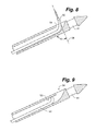
- FIG. 8 is a schematic drawing of an alternate embodiment of the distal tip region of a working section with a guide tube advanced outside the working section;
- FIG. 9 is schematic drawing of an alternate embodiment of the distal tip region of a working section with a guide tube retracted within the working section.
- FIG. 10 is a cross section of an embodiment of the proximal handle portion of the working catheter.
- FIG. 1 shows a patient 10 with a complex occlusion 13 involving several vessels in neck region above the level of the superior vena cava and the right atrium near reference numeral 15 .
- the working section 18 of the elongate working catheter 20 has entered the occlusion 13 via blunt dissection.
- the blunt dissection distal tip 22 of the working section 18 is being pushed in to the occlusion by forces applied to a handle (not seen in this view) attached to the proximal end of the elongate working catheter 20 .
- the user is advancing the blunt dissection tip toward the patient's head. This motion will place the blunt tip 22 in the vicinity of the radiopaque marker 30 on the surface of the patient.
- a delivery sheath 24 of conventional design used to help position the elongate working catheter 20 at the stump 26 of the occlusion.
- FIG. 2 shows that the radiopaque target 30 placed on the surface of the patient 10 serves to define a desired exit point 40 on the surface of the patient.
- the closed end blunt dissection tip 22 is imaged via fluoroscopy (anterior/posterior) and the tip 22 is moved to a desired distal end location 36 .
- the C-arm cranial angle is observed and it is used to set the departure angle.
- the C-arm is moved to image the tip 22 through the target 30 .
- the angular location of the blunt tip is determined by a slot feature in the blunt dissection tip, this feature is seen better in detail FIG. 5 .
- the opacity of the slot varies and this changing image feature is used to determine the orientation of the exit plane of the departure angle guide.
- the C-arm is moved to image the tip 22 through the target 30 .
- the C-arm cranial angle is observed and it is used to set the departure angle that defines a tissue track 38 angle that aims the sharp dissection tip of the needle wire 32 toward the central aperture of the radiopaque target 30 via forces supplied by the user to the needle wire 32 through a handle not seen in this view.
- the needle wire 32 exteriorized as seen in the figure the access provided to the end of the wire allows additional intervention at the exit wound site as described below.
- FIG. 3 shows the catheter system 12 in isolation.
- the shaft of the working catheter 20 is connected to a handle 28 through a strain relief 14 .
- the distal working section of the catheter 18 and the shaft of the working catheter 20 are sufficiently push-able and torque-able to allow the blunt dissection tip 22 to be forced into the occlusion.
- Experimentation has established that an appropriate value of bending stiffness is around 52 (pounds force) times (inches squared).
- a stainless steel tube with an inside diameter of 0.074 inches and outside diameter of 0.094 inches is sufficient for this purpose and meets this parameter.
- variable wall thickness structures and otherwise flexible materials can be readily substituted. For example braided nitinol embedding in a polymer or a laser cut hypodermic tube may be used.
- the functional characteristic required is sufficient push-ability and torque-ability to permit entry into the occlusion via blunt dissection.
- the magnitude of the forces required also depend on the “sharpness” of the blunt dissection tip 22 feature and the overall diameter of the blunt tip itself. In general the tip is blunt enough that it will not penetrate skin if it is touched while handling the catheter.
- FIG. 4 and FIG. 5 should be considered together, where FIG. 4 shows details of the handle 28 and FIG. 5 shows details of the tip.
- the rotary knob 16 may turned or twisted ( FIG. 4 ) to advance the needle wire departure angle guide tube out of the blunt dissection tip 22 side aperture 21 ( FIG. 5 ).
- the position of the needle wire departure angle guide tube 34 and the departure angle is read from a gauge 17 in the handle 28 .
- the knob sets the departure angle which is read from the gauge on the handle.
- the plane of the departure angle guide is set by the rotation of the handle 28 itself and visualization of the opacity of the aperture feature 21 in the distal tip.
- a wire clamping and propelling system located within the handle 28 allows the user to advance the needle wire 32 out of the handle with a “pumping motion”, as indicated by motion arrow 27 .
- This may be achieved in this embodiment by reciprocating the sliding pommel 25 to advance the needle wire 32 through the handle and out of the needle wire departure angle guide tube 34 along path 38 defined by the rotational plane of the needle wire departure angle guide tube and the location 26 ( FIG. 1 ) of the blunt dissection distal tip 22 relative to the target 30 ( FIG. 1 and FIG. 2 ).
- FIG. 6 and FIG. 7 should be considered together. Together they illustrate the use of the radiopaque marker 30 positioned on the surface of the patient to facilitate catheter setup and aiming.
- the goal is to quickly, via C-arm fluoroscopy determine the optimal distal tip location or position 36 as well as the optimal departure angle (theta in the figure) that correspond to the alignment of the needle wire 32 with the central aperture 31 of target 30 .
- the distal tip position 36 and departure angle theta the tissue track 38 traversed by the needle wire 32 will track in a straight line and exit the body at the desired and pre-defined location.
- FIG. 6 shows the relationship between tip location 36 and the appropriate departure angle theta. In the figure the anatomic structures are not shown to simplify and clarify the figure.
- FIG. 7 is a schematic and simplified and highly stylized view of the image the user would see via C-Arm fluoroscopy.
- the blunt dissection tip 22 has a slot aperture 41 that can be view through the central aperture 31 of radiopaque target 30 .
- the opacity of the slot 41 will vary with the rotation indicated by motion arrow “R” of the working section of the catheter.
- the slot will appear brightest when the plane of the needle wire guide tube is “aimed” at the central aperture 31 that is the plane of the guide tube intersects the exit point on the patient.
- the viewing axis of the fluoroscope (VAF) is aligned with the target which is assumed to be the case in this description.
- the user will advance or retract the tip 22 (“D”) and rotate (“R”) the working section 18 to optimize the location of the planned tissue track 38 .
- an angle corresponding to theta is read off the C-Arm and used to set the guide tube position or departure angle.
- the knob 16 is twisted until the scale 17 corresponds to the desired departure angle.
- the angular range varies from about 15 degrees to 60 degrees as indicated on the handle. This corresponds to the operational angle seen on FIG. 6 of about 75 degrees to 30 degrees as measured perpendicular to the axis of the shaft.
- FIG. 8 and FIG. 9 should be considered together. They represent an alternative embodiment of the system where the needle wire departure angle guide tube 50 has a fixed value that is not adjustable by the user.
- the fixed departure angle device differed from the variable angle device in that a degree of freedom is eliminated. That is the linear travel of the needle guide with respect to the tip have only one correct value to achieve target aiming. Only the distal section of the device is shown and the remaining details of handle construction are well known to those of skill in the art and need not be further described.
- the super-elastic departure angle guide tube 50 has a value of approximately 90 degrees in FIG. 8 . As the needle wire departure angle guide tube is advanced distally within lumen 52 it emerges through a port 54 and assumes it preset configuration defining tissue track 38 .
- FIG. 10 is a cross section of the handle with an illustrative implementation of structures for carrying out the wire management and departure angle setting features.
- This embodiment is intended to be illustrative but not limiting. Some items described previously are absent from this view to simplify and clarify the operation of the handle.
- the handle is approximately cylindrical with a central axis. A portion of the needle wire departure guide tube is seen at 34 . Rotation of the knob 16 turns a screw that advances or retracts the tube 34 depending upon direction of rotation. The position of the tube and therefore the departure angle is indicated by the position of post 60 in its companion slot. The user twists the knob 16 until the indicator post indicates the desired departure angle as read from the gauge or scale 17 seen best in FIG. 4 .
- the pommel 25 interacts with a J-arm clamp 62 that is pivoted 64 to wedge against the wire 32 as the pommel is advanced distally in the handle.
- the return stroke allows the J-arm clamp to release the wire which will remain stationary while the pommel is moved again to its start position in preparation for another stroke of wire advancement.
- the pommel and handle structures together support the wire 32 during the stroke so that the wire does not bend or kink.
- the stroke is relatively fixed so that a user may count the number of pommel strokes to have an estimate of how much wire has been advanced out the guide tube.
- An optional locking and releasing structure 66 can be used to connect the wire to the handle so the withdrawal of the handle also pulls the wire 32 or alternatively the wire 32 maybe released entirely from the handle to allow the wire 32 to remain in the body while the handle and associated structures are removed from the body over the wire.
Abstract
Description
Claims (4)
Priority Applications (1)
| Application Number | Priority Date | Filing Date | Title |
|---|---|---|---|
| US14/656,964 US9289577B2 (en) | 2012-02-09 | 2015-03-13 | Occlusion access method |
Applications Claiming Priority (3)
| Application Number | Priority Date | Filing Date | Title |
|---|---|---|---|
| US201261596834P | 2012-02-09 | 2012-02-09 | |
| US13/680,327 US10092726B2 (en) | 2012-02-09 | 2012-11-19 | Occlusion access system |
| US14/656,964 US9289577B2 (en) | 2012-02-09 | 2015-03-13 | Occlusion access method |
Related Parent Applications (1)
| Application Number | Title | Priority Date | Filing Date |
|---|---|---|---|
| US13/680,327 Continuation US10092726B2 (en) | 2012-02-09 | 2012-11-19 | Occlusion access system |
Publications (2)
| Publication Number | Publication Date |
|---|---|
| US20150182727A1 US20150182727A1 (en) | 2015-07-02 |
| US9289577B2 true US9289577B2 (en) | 2016-03-22 |
Family
ID=50728597
Family Applications (3)
| Application Number | Title | Priority Date | Filing Date |
|---|---|---|---|
| US13/680,327 Active 2033-08-13 US10092726B2 (en) | 2012-02-09 | 2012-11-19 | Occlusion access system |
| US14/656,964 Active US9289577B2 (en) | 2012-02-09 | 2015-03-13 | Occlusion access method |
| US16/154,106 Active 2035-04-29 US11383065B2 (en) | 2012-02-09 | 2018-10-08 | Occlusion access method |
Family Applications Before (1)
| Application Number | Title | Priority Date | Filing Date |
|---|---|---|---|
| US13/680,327 Active 2033-08-13 US10092726B2 (en) | 2012-02-09 | 2012-11-19 | Occlusion access system |
Family Applications After (1)
| Application Number | Title | Priority Date | Filing Date |
|---|---|---|---|
| US16/154,106 Active 2035-04-29 US11383065B2 (en) | 2012-02-09 | 2018-10-08 | Occlusion access method |
Country Status (1)
| Country | Link |
|---|---|
| US (3) | US10092726B2 (en) |
Cited By (3)
| Publication number | Priority date | Publication date | Assignee | Title |
|---|---|---|---|---|
| US11045224B2 (en) | 2018-09-24 | 2021-06-29 | University Of Maryland, Baltimore | Apparatus and method for septal punch |
| US11523808B2 (en) | 2017-03-22 | 2022-12-13 | University Of Maryland, Baltimore | Device and method for transseptal puncture |
| US20230173230A1 (en) * | 2012-02-09 | 2023-06-08 | Bluegrass Vascular Technologies, Inc. | Occlusion access method |
Families Citing this family (16)
| Publication number | Priority date | Publication date | Assignee | Title |
|---|---|---|---|---|
| US9511214B2 (en) | 2006-05-02 | 2016-12-06 | Vascular Access Technologies, Inc. | Methods of transvascular retrograde access placement and devices for facilitating therein |
| WO2011068540A1 (en) | 2009-12-03 | 2011-06-09 | Therix Medical Development, Ltd. | Central venous access system |
| US8377034B2 (en) | 2009-12-04 | 2013-02-19 | Std Med, Inc. | Vascular access port |
| US10092726B2 (en) | 2012-02-09 | 2018-10-09 | Bluegrass Vascular Technologies, Inc. | Occlusion access system |
| US9623217B2 (en) | 2012-05-30 | 2017-04-18 | Vascular Access Techonlogies, Inc. | Transvascular access methods |
| US9220874B2 (en) | 2012-05-30 | 2015-12-29 | Vascular Access Technologies, Inc. | Transvascular access device and method |
| JP6568200B2 (en) | 2014-04-03 | 2019-08-28 | ヴェルサゴ ヴァスキュラー アクセス インコーポレイテッド | Device for attaching and removing the needle tip of a needle |
| JP6173287B2 (en) * | 2014-09-30 | 2017-08-02 | 富士フイルム株式会社 | Endoscope device |
| JP6110828B2 (en) * | 2014-09-30 | 2017-04-05 | 富士フイルム株式会社 | Endoscope device |
| JP6837971B2 (en) | 2014-12-18 | 2021-03-03 | ヴェルサゴ ヴァスキュラー アクセス インコーポレイテッド | Catheter patency system and method |
| JP6879946B2 (en) | 2015-07-14 | 2021-06-02 | ヴェルサゴ ヴァスキュラー アクセス インコーポレイテッド | Medical access ports, transport devices and how to use them |
| EP3422968B1 (en) * | 2016-02-29 | 2022-12-14 | Bluegrass Vascular Technologies, Inc. | Catheter systems for gaining access to a vessel |
| US10617854B2 (en) | 2016-12-09 | 2020-04-14 | Vascular Access Technologies, Inc. | Trans-jugular carotid artery access methods |
| US11654224B2 (en) | 2016-12-30 | 2023-05-23 | Vascular Access Technologies, Inc. | Methods and devices for percutaneous implantation of arterio-venous grafts |
| CA3086211A1 (en) | 2017-12-21 | 2019-06-27 | Versago Vascular Access, Inc. | Medical access ports, transfer devices and methods of use thereof |
| US10932815B1 (en) * | 2019-01-02 | 2021-03-02 | Indian Wells Medical, Inc. | Steerable endoluminal punch |
Citations (39)
| Publication number | Priority date | Publication date | Assignee | Title |
|---|---|---|---|---|
| US4559039A (en) | 1983-12-05 | 1985-12-17 | Purdue Research Foundation | Permanently placed transcutaneous access device to blood vessels |
| US5152749A (en) | 1991-06-28 | 1992-10-06 | American Medical Systems, Inc. | Instrument placement apparatus |
| US5800378A (en) | 1992-08-12 | 1998-09-01 | Vidamed, Inc. | Medical probe device and method |
| US5851195A (en) | 1995-05-17 | 1998-12-22 | Gill; Inderbir S. | Direct percutaneous endoscopic jejunostomy method and apparatus |
| US6190353B1 (en) | 1995-10-13 | 2001-02-20 | Transvascular, Inc. | Methods and apparatus for bypassing arterial obstructions and/or performing other transvascular procedures |
| US20010016752A1 (en) | 1998-01-28 | 2001-08-23 | St. Jude Medical Cardiovascular Group, Inc. | Vessel cutting devices |
| US20020022857A1 (en) | 1996-11-07 | 2002-02-21 | St. Jude Medical Cardiovascular Group, Inc. | Medical grafting methods and apparatus |
| US6475226B1 (en) | 1999-02-03 | 2002-11-05 | Scimed Life Systems, Inc. | Percutaneous bypass apparatus and method |
| US20030191449A1 (en) | 1999-08-05 | 2003-10-09 | Kensey Nash Corporation | Systems for delivering agents into targeted tissue of a living being |
| US20030220698A1 (en) | 2000-04-26 | 2003-11-27 | Dana Mears | Method and apparatus for performing a minimally invasive total hip arthroplasty |
| US6662036B2 (en) | 1991-01-28 | 2003-12-09 | Sherwood Services Ag | Surgical positioning system |
| US6726677B1 (en) | 1995-10-13 | 2004-04-27 | Transvascular, Inc. | Stabilized tissue penetrating catheters |
| US20040165966A1 (en) | 2002-12-18 | 2004-08-26 | Aukzemas Thomas V. | Telescopic captive fastener |
| US20040181150A1 (en) | 1999-09-01 | 2004-09-16 | Bacchus Vascular, Inc. | Methods and apparatus for accessing and treating body lumens |
| US20040199177A1 (en) | 1996-06-14 | 2004-10-07 | Ducksoo Kim | Catheter apparatus having an improved shape-memory alloy cuff and inflatable on-demand balloon for creating a bypass graft in-vivo |
| US20050125002A1 (en) | 2003-10-31 | 2005-06-09 | George Baran | System and method for manipulating a catheter for delivering a substance to a body cavity |
| US20060106288A1 (en) | 2004-11-17 | 2006-05-18 | Roth Alex T | Remote tissue retraction device |
| US7179220B2 (en) | 2001-02-07 | 2007-02-20 | Siemens Corporate Research, Inc. | Method for guiding flexible instrument procedures |
| US20070135803A1 (en) | 2005-09-14 | 2007-06-14 | Amir Belson | Methods and apparatus for performing transluminal and other procedures |
| US20070166345A1 (en) | 2003-11-28 | 2007-07-19 | Dusan Pavcnik | Vascular occlusion methods, systems and devices |
| US20070203517A1 (en) | 2005-09-27 | 2007-08-30 | Williams Michael S | Transgastric surgical devices and procedures |
| US20080230070A1 (en) | 2007-03-20 | 2008-09-25 | Felix Gregorian | Endotracheal Tube with Radiopaque Distal End Marker |
| US20090005755A1 (en) | 2002-11-22 | 2009-01-01 | Keith Peter T | Guide wire control catheter for crossing occlusions and related methods of use |
| US20090281379A1 (en) | 2008-05-12 | 2009-11-12 | Xlumena, Inc. | System and method for transluminal access |
| US7635353B2 (en) | 2004-09-22 | 2009-12-22 | St. Jude Medical, Atrial Fibrillation Division, Inc. | Transseptal puncture needles and needle assemblies |
| US20100056862A1 (en) | 2008-09-03 | 2010-03-04 | Ethicon Endo-Surgery, Inc. | Access needle for natural orifice translumenal endoscopic surgery |
| US7678081B2 (en) | 2004-07-12 | 2010-03-16 | Pacesetter, Inc. | Methods and devices for transseptal access |
| WO2011068540A1 (en) | 2009-12-03 | 2011-06-09 | Therix Medical Development, Ltd. | Central venous access system |
| US8029470B2 (en) | 2004-09-30 | 2011-10-04 | Pacesetter, Inc. | Transmembrane access systems and methods |
| US20120136247A1 (en) | 2006-05-02 | 2012-05-31 | Lakshmikumar Pillai | Methods of Transvascular Retrograde Access Placement and Devices for Facilitating the Placement |
| US20120239069A1 (en) | 2011-03-17 | 2012-09-20 | Medtronic, Inc. | Transseptal Puncturing Device |
| US8337518B2 (en) | 2006-12-20 | 2012-12-25 | Onset Medical Corporation | Expandable trans-septal sheath |
| US8357193B2 (en) | 2009-05-29 | 2013-01-22 | Xlumena, Inc. | Apparatus and method for deploying stent across adjacent tissue layers |
| US20130197621A1 (en) | 2010-08-12 | 2013-08-01 | Silk Road Medical, Inc. | Systems and methods for treating a carotid artery |
| US8500768B2 (en) | 2010-05-11 | 2013-08-06 | Cardiac Inventions Unlimited Inc. | Apparatus for safe performance of transseptal technique and placement and positioning of an ablation catheter |
| US8568435B2 (en) | 2009-08-21 | 2013-10-29 | Vascular Access Technologies, Inc. | Transvascular retrograde access devices |
| US20140142418A1 (en) | 2012-02-09 | 2014-05-22 | Therix Medical Development, Ltd. | Occlusion access system |
| US8771287B2 (en) | 2010-11-15 | 2014-07-08 | Jason Benjamin Wynberg | Percutaneous renal access system |
| US8795310B2 (en) | 2010-04-13 | 2014-08-05 | Sentreheart, Inc. | Methods and devices for accessing and delivering devices to a heart |
Family Cites Families (10)
| Publication number | Priority date | Publication date | Assignee | Title |
|---|---|---|---|---|
| US6217527B1 (en) * | 1998-09-30 | 2001-04-17 | Lumend, Inc. | Methods and apparatus for crossing vascular occlusions |
| WO1999062415A1 (en) | 1998-05-29 | 1999-12-09 | By-Pass, Inc. | Methods and devices for vascular surgery |
| JP4653104B2 (en) * | 2003-06-10 | 2011-03-16 | ルーメンド インコーポレイテッド | Catheter apparatus and method for opening a vascular occlusion |
| US8241315B2 (en) * | 2004-06-24 | 2012-08-14 | Boston Scientific Scimed, Inc. | Apparatus and method for treating occluded vasculature |
| US7751868B2 (en) | 2004-11-12 | 2010-07-06 | Philips Electronics Ltd | Integrated skin-mounted multifunction device for use in image-guided surgery |
| WO2006105244A2 (en) | 2005-03-30 | 2006-10-05 | Lumend, Inc. | Catheter systems for crossing total occlusions in vasculature |
| WO2008070262A2 (en) | 2006-10-06 | 2008-06-12 | The Cleveland Clinic Foundation | Apparatus and method for targeting a body tissue |
| US8900214B2 (en) | 2007-03-30 | 2014-12-02 | Onset Medical Corporation | Expandable trans-septal sheath |
| EP2259830B1 (en) | 2008-02-05 | 2017-08-16 | Bridgepoint Medical, Inc. | Crossing occlusions in blood vessels |
| US8814873B2 (en) | 2011-06-24 | 2014-08-26 | Benvenue Medical, Inc. | Devices and methods for treating bone tissue |
-
2012
- 2012-11-19 US US13/680,327 patent/US10092726B2/en active Active
-
2015
- 2015-03-13 US US14/656,964 patent/US9289577B2/en active Active
-
2018
- 2018-10-08 US US16/154,106 patent/US11383065B2/en active Active
Patent Citations (42)
| Publication number | Priority date | Publication date | Assignee | Title |
|---|---|---|---|---|
| US4559039A (en) | 1983-12-05 | 1985-12-17 | Purdue Research Foundation | Permanently placed transcutaneous access device to blood vessels |
| US6662036B2 (en) | 1991-01-28 | 2003-12-09 | Sherwood Services Ag | Surgical positioning system |
| US5152749A (en) | 1991-06-28 | 1992-10-06 | American Medical Systems, Inc. | Instrument placement apparatus |
| US5800378A (en) | 1992-08-12 | 1998-09-01 | Vidamed, Inc. | Medical probe device and method |
| US5851195A (en) | 1995-05-17 | 1998-12-22 | Gill; Inderbir S. | Direct percutaneous endoscopic jejunostomy method and apparatus |
| US6726677B1 (en) | 1995-10-13 | 2004-04-27 | Transvascular, Inc. | Stabilized tissue penetrating catheters |
| US6655386B1 (en) | 1995-10-13 | 2003-12-02 | Transvascular, Inc. | Transluminal method for bypassing arterial obstructions |
| US7059330B1 (en) | 1995-10-13 | 2006-06-13 | Medtronic Vascular, Inc. | Methods and apparatus for bypassing arterial obstructions and/or performing other transvascular procedures |
| US6190353B1 (en) | 1995-10-13 | 2001-02-20 | Transvascular, Inc. | Methods and apparatus for bypassing arterial obstructions and/or performing other transvascular procedures |
| US7134438B2 (en) | 1995-10-13 | 2006-11-14 | Medtronic Vascular, Inc. | Methods and apparatus for bypassing arterial obstructions and/or performing other transvascular procedures |
| US20040199177A1 (en) | 1996-06-14 | 2004-10-07 | Ducksoo Kim | Catheter apparatus having an improved shape-memory alloy cuff and inflatable on-demand balloon for creating a bypass graft in-vivo |
| US20020022857A1 (en) | 1996-11-07 | 2002-02-21 | St. Jude Medical Cardiovascular Group, Inc. | Medical grafting methods and apparatus |
| US20010016752A1 (en) | 1998-01-28 | 2001-08-23 | St. Jude Medical Cardiovascular Group, Inc. | Vessel cutting devices |
| US6475226B1 (en) | 1999-02-03 | 2002-11-05 | Scimed Life Systems, Inc. | Percutaneous bypass apparatus and method |
| US20030191449A1 (en) | 1999-08-05 | 2003-10-09 | Kensey Nash Corporation | Systems for delivering agents into targeted tissue of a living being |
| US20040181150A1 (en) | 1999-09-01 | 2004-09-16 | Bacchus Vascular, Inc. | Methods and apparatus for accessing and treating body lumens |
| US20030220698A1 (en) | 2000-04-26 | 2003-11-27 | Dana Mears | Method and apparatus for performing a minimally invasive total hip arthroplasty |
| US7179220B2 (en) | 2001-02-07 | 2007-02-20 | Siemens Corporate Research, Inc. | Method for guiding flexible instrument procedures |
| US20090005755A1 (en) | 2002-11-22 | 2009-01-01 | Keith Peter T | Guide wire control catheter for crossing occlusions and related methods of use |
| US20040165966A1 (en) | 2002-12-18 | 2004-08-26 | Aukzemas Thomas V. | Telescopic captive fastener |
| US20050125002A1 (en) | 2003-10-31 | 2005-06-09 | George Baran | System and method for manipulating a catheter for delivering a substance to a body cavity |
| US20070166345A1 (en) | 2003-11-28 | 2007-07-19 | Dusan Pavcnik | Vascular occlusion methods, systems and devices |
| US7678081B2 (en) | 2004-07-12 | 2010-03-16 | Pacesetter, Inc. | Methods and devices for transseptal access |
| US7635353B2 (en) | 2004-09-22 | 2009-12-22 | St. Jude Medical, Atrial Fibrillation Division, Inc. | Transseptal puncture needles and needle assemblies |
| US8029470B2 (en) | 2004-09-30 | 2011-10-04 | Pacesetter, Inc. | Transmembrane access systems and methods |
| US20060106288A1 (en) | 2004-11-17 | 2006-05-18 | Roth Alex T | Remote tissue retraction device |
| US20070135803A1 (en) | 2005-09-14 | 2007-06-14 | Amir Belson | Methods and apparatus for performing transluminal and other procedures |
| US20070203517A1 (en) | 2005-09-27 | 2007-08-30 | Williams Michael S | Transgastric surgical devices and procedures |
| US20120136247A1 (en) | 2006-05-02 | 2012-05-31 | Lakshmikumar Pillai | Methods of Transvascular Retrograde Access Placement and Devices for Facilitating the Placement |
| US8337518B2 (en) | 2006-12-20 | 2012-12-25 | Onset Medical Corporation | Expandable trans-septal sheath |
| US20080230070A1 (en) | 2007-03-20 | 2008-09-25 | Felix Gregorian | Endotracheal Tube with Radiopaque Distal End Marker |
| US20090281379A1 (en) | 2008-05-12 | 2009-11-12 | Xlumena, Inc. | System and method for transluminal access |
| US20100056862A1 (en) | 2008-09-03 | 2010-03-04 | Ethicon Endo-Surgery, Inc. | Access needle for natural orifice translumenal endoscopic surgery |
| US8357193B2 (en) | 2009-05-29 | 2013-01-22 | Xlumena, Inc. | Apparatus and method for deploying stent across adjacent tissue layers |
| US8568435B2 (en) | 2009-08-21 | 2013-10-29 | Vascular Access Technologies, Inc. | Transvascular retrograde access devices |
| WO2011068540A1 (en) | 2009-12-03 | 2011-06-09 | Therix Medical Development, Ltd. | Central venous access system |
| US8795310B2 (en) | 2010-04-13 | 2014-08-05 | Sentreheart, Inc. | Methods and devices for accessing and delivering devices to a heart |
| US8500768B2 (en) | 2010-05-11 | 2013-08-06 | Cardiac Inventions Unlimited Inc. | Apparatus for safe performance of transseptal technique and placement and positioning of an ablation catheter |
| US20130197621A1 (en) | 2010-08-12 | 2013-08-01 | Silk Road Medical, Inc. | Systems and methods for treating a carotid artery |
| US8771287B2 (en) | 2010-11-15 | 2014-07-08 | Jason Benjamin Wynberg | Percutaneous renal access system |
| US20120239069A1 (en) | 2011-03-17 | 2012-09-20 | Medtronic, Inc. | Transseptal Puncturing Device |
| US20140142418A1 (en) | 2012-02-09 | 2014-05-22 | Therix Medical Development, Ltd. | Occlusion access system |
Non-Patent Citations (5)
| Title |
|---|
| Apr. 30, 2013 PCT Search Report (Serial No. PCT/US20131024738)-Our Matter 4950. |
| Feb. 18, 2014 PCT Preliminary Examination Report (Serial No. PCT/US2013/024738)-Our Matter 4950. |
| Jan. 29, 2014 USPTO Office Action (U.S. Appl. No. 13/680,327)-Our Matter 4888. |
| May 29, 2014 USPTO Office Action (Serial No. 13/680,327)-Our Matter 4888. |
| Nov. 7, 2014 USPTO Office Action (U.S. Appl. No. 13/680,327)-Our Matter 4888. |
Cited By (6)
| Publication number | Priority date | Publication date | Assignee | Title |
|---|---|---|---|---|
| US20230173230A1 (en) * | 2012-02-09 | 2023-06-08 | Bluegrass Vascular Technologies, Inc. | Occlusion access method |
| US11806485B2 (en) * | 2012-02-09 | 2023-11-07 | Merit Medical Systems, Inc. | Occlusion access method |
| US11523808B2 (en) | 2017-03-22 | 2022-12-13 | University Of Maryland, Baltimore | Device and method for transseptal puncture |
| US11045224B2 (en) | 2018-09-24 | 2021-06-29 | University Of Maryland, Baltimore | Apparatus and method for septal punch |
| US11154325B2 (en) | 2018-09-24 | 2021-10-26 | University Of Maryland, Baltimore | Apparatus and method for septal punch |
| US11172960B2 (en) | 2018-09-24 | 2021-11-16 | University Of Maryland, Baltimore | Apparatus and method for septal punch |
Also Published As
| Publication number | Publication date |
|---|---|
| US20140142418A1 (en) | 2014-05-22 |
| US11383065B2 (en) | 2022-07-12 |
| US10092726B2 (en) | 2018-10-09 |
| US20150182727A1 (en) | 2015-07-02 |
| US20190209808A1 (en) | 2019-07-11 |
Similar Documents
| Publication | Publication Date | Title |
|---|---|---|
| US11383065B2 (en) | Occlusion access method | |
| US11806485B2 (en) | Occlusion access method | |
| US11801065B2 (en) | Catheter systems, kits, and methods for gaining access to a vessel | |
| US5221269A (en) | Guide for localizing a nonpalpable breast lesion | |
| EP2259832B1 (en) | Transseptal guidewire | |
| CN111601633A (en) | Transseptal guide wire puncture system | |
| US20130274783A1 (en) | Percutaneous renal access system | |
| JP2022153554A (en) | Methods and devices for puncturing tissue | |
| US20230371936A1 (en) | Transseptal systems, devices and methods | |
| US20150202410A1 (en) | Apparatuses for steering catheters | |
| US10624669B2 (en) | Image-guided drainage of abscesses | |
| EP3662963A1 (en) | Drainage catheter and guide wire introducer kit |
Legal Events
| Date | Code | Title | Description |
|---|---|---|---|
| AS | Assignment |
Owner name: BLUEGRASS VASCULAR TECHNOLOGIES, INC., TEXAS Free format text: ASSIGNMENT OF ASSIGNORS INTEREST;ASSIGNOR:THERIX MEDICAL DEVELOPMENT, LTD.;REEL/FRAME:037402/0346 Effective date: 20151117 |
|
| STCF | Information on status: patent grant |
Free format text: PATENTED CASE |
|
| AS | Assignment |
Owner name: THERIX MEDICAL DEVELOPMENT, LTD., KENTUCKY Free format text: ASSIGNMENT OF ASSIGNORS INTEREST;ASSIGNORS:GURLEY, JOHN;TRAUTMAN, JOSEPH GREAGAN;DE LA MENARDIERE, BRICE ARNAULT;AND OTHERS;SIGNING DATES FROM 20121112 TO 20121118;REEL/FRAME:040501/0427 |
|
| AS | Assignment |
Owner name: THERIX MEDICAL DEVELOPMENT, LTD., KENTUCKY Free format text: CORRECTIVE ASSIGNMENT TO CORRECT THE CONVEYING PARTY DATA PREVIOUSLY RECORDED ON REEL 040501 FRAME 0427. ASSIGNOR(S) HEREBY CONFIRMS THE ASSIGNMENT;ASSIGNORS:GURLEY, JOHN;TRAUTMAN, JOSEPH CREAGAN;DE LA MENARDIERE, BRICE ARNAULT;AND OTHERS;SIGNING DATES FROM 20121112 TO 20121118;REEL/FRAME:041256/0990 |
|
| AS | Assignment |
Owner name: MERIT MEDICAL SYSTEMS, INC., UTAH Free format text: SECURITY INTEREST;ASSIGNOR:BLUEGRASS VASCULAR TECHNOLOGIES, INC.;REEL/FRAME:041003/0133 Effective date: 20161219 |
|
| MAFP | Maintenance fee payment |
Free format text: PAYMENT OF MAINTENANCE FEE, 4TH YR, SMALL ENTITY (ORIGINAL EVENT CODE: M2551); ENTITY STATUS OF PATENT OWNER: SMALL ENTITY Year of fee payment: 4 |
|
| AS | Assignment |
Owner name: BLUEGRASS VASCULAR TECHNOLOGIES, INC., TEXAS Free format text: RELEASE BY SECURED PARTY;ASSIGNOR:MERIT MEDICAL SYSTEMS, INC.;REEL/FRAME:058409/0574 Effective date: 20211201 |
|
| AS | Assignment |
Owner name: MERIT MEDICAL SYSTEMS, INC., UTAH Free format text: ASSIGNMENT OF ASSIGNORS INTEREST;ASSIGNOR:BLUEGRASS VASCULAR TECHNOLOGIES, INC.;REEL/FRAME:063745/0189 Effective date: 20230504 Owner name: THERIX MEDICAL DEVELOPEMENT, LTD., KENTUCKY Free format text: ASSIGNMENT OF ASSIGNORS INTEREST;ASSIGNORS:GURLEY, JOHN;TRAUTMAN, JOSEPH CREAGAN;DE LA MENARDIERE, BRICE ARNAULT;AND OTHERS;SIGNING DATES FROM 20230501 TO 20230502;REEL/FRAME:063745/0113 |
|
| FEPP | Fee payment procedure |
Free format text: ENTITY STATUS SET TO UNDISCOUNTED (ORIGINAL EVENT CODE: BIG.); ENTITY STATUS OF PATENT OWNER: LARGE ENTITY |
|
| MAFP | Maintenance fee payment |
Free format text: PAYMENT OF MAINTENANCE FEE, 8TH YEAR, LARGE ENTITY (ORIGINAL EVENT CODE: M1552); ENTITY STATUS OF PATENT OWNER: LARGE ENTITY Year of fee payment: 8 |
|
| AS | Assignment |
Owner name: THERIX MEDICAL DEVELOPEMENT, LTD., KENTUCKY Free format text: ASSIGNMENT OF ASSIGNORS INTEREST;ASSIGNORS:GURLEY, JOHN;TRAUTMAN, JOSEPH CREAGAN;DE LA MENARDIERE, BRICE ARNAULT;AND OTHERS;SIGNING DATES FROM 20230501 TO 20230502;REEL/FRAME:065811/0677 |