US9289074B1 - Sleeping system and method for adjusting the same - Google Patents
Sleeping system and method for adjusting the same Download PDFInfo
- Publication number
- US9289074B1 US9289074B1 US13/090,331 US201113090331A US9289074B1 US 9289074 B1 US9289074 B1 US 9289074B1 US 201113090331 A US201113090331 A US 201113090331A US 9289074 B1 US9289074 B1 US 9289074B1
- Authority
- US
- United States
- Prior art keywords
- firmness
- layer
- section
- comfort
- foundation
- Prior art date
- Legal status (The legal status is an assumption and is not a legal conclusion. Google has not performed a legal analysis and makes no representation as to the accuracy of the status listed.)
- Expired - Fee Related, expires
Links
- 238000000034 method Methods 0.000 title abstract description 17
- 238000010276 construction Methods 0.000 claims description 13
- 239000000463 material Substances 0.000 description 27
- 229910000831 Steel Inorganic materials 0.000 description 6
- 239000010959 steel Substances 0.000 description 6
- 229920001821 foam rubber Polymers 0.000 description 5
- 229920000079 Memory foam Polymers 0.000 description 4
- 230000008859 change Effects 0.000 description 4
- 239000008210 memory foam Substances 0.000 description 4
- 239000002023 wood Substances 0.000 description 4
- 229920005830 Polyurethane Foam Polymers 0.000 description 3
- 230000004075 alteration Effects 0.000 description 3
- 230000008901 benefit Effects 0.000 description 3
- 239000004744 fabric Substances 0.000 description 3
- 239000000203 mixture Substances 0.000 description 3
- 239000011496 polyurethane foam Substances 0.000 description 3
- 238000004026 adhesive bonding Methods 0.000 description 2
- 230000012447 hatching Effects 0.000 description 2
- 239000004816 latex Substances 0.000 description 2
- 229920000126 latex Polymers 0.000 description 2
- 238000004519 manufacturing process Methods 0.000 description 2
- 238000012986 modification Methods 0.000 description 2
- 230000004048 modification Effects 0.000 description 2
- 238000009958 sewing Methods 0.000 description 2
- 238000012360 testing method Methods 0.000 description 2
- 229920000742 Cotton Polymers 0.000 description 1
- 230000003466 anti-cipated effect Effects 0.000 description 1
- 238000011161 development Methods 0.000 description 1
- 230000018109 developmental process Effects 0.000 description 1
- 238000005516 engineering process Methods 0.000 description 1
- 239000006260 foam Substances 0.000 description 1
- 230000006870 function Effects 0.000 description 1
- 230000008569 process Effects 0.000 description 1
- 238000011160 research Methods 0.000 description 1
- 238000006467 substitution reaction Methods 0.000 description 1
- -1 wool Polymers 0.000 description 1
- 210000002268 wool Anatomy 0.000 description 1
Images


Classifications
-
- A—HUMAN NECESSITIES
- A47—FURNITURE; DOMESTIC ARTICLES OR APPLIANCES; COFFEE MILLS; SPICE MILLS; SUCTION CLEANERS IN GENERAL
- A47C—CHAIRS; SOFAS; BEDS
- A47C27/00—Spring, stuffed or fluid mattresses or cushions specially adapted for chairs, beds or sofas
- A47C27/14—Spring, stuffed or fluid mattresses or cushions specially adapted for chairs, beds or sofas with foamed material inlays
- A47C27/148—Spring, stuffed or fluid mattresses or cushions specially adapted for chairs, beds or sofas with foamed material inlays of different resilience
-
- A—HUMAN NECESSITIES
- A47—FURNITURE; DOMESTIC ARTICLES OR APPLIANCES; COFFEE MILLS; SPICE MILLS; SUCTION CLEANERS IN GENERAL
- A47C—CHAIRS; SOFAS; BEDS
- A47C27/00—Spring, stuffed or fluid mattresses or cushions specially adapted for chairs, beds or sofas
- A47C27/14—Spring, stuffed or fluid mattresses or cushions specially adapted for chairs, beds or sofas with foamed material inlays
- A47C27/15—Spring, stuffed or fluid mattresses or cushions specially adapted for chairs, beds or sofas with foamed material inlays consisting of two or more layers
Definitions
- a sleeping system that provides at least six different firmness levels per bed, which may adjusted by an end user.
- the present invention may be reconfigured in a variety of ways in order to provide a user the convenience of an altered firmness level with little effort.
- a method of selling the sleeping system by using minimal retail floor space Also disclosed is a method of exchanging the comfort layer of the sleeping system after it has been sold in order to provide the user with further alternate firmness levels. That is, the invention disclosed herein provides the benefit of a single sleeping system having modular components so that, after it is sold, the comfort layer may be easily exchanged for a new or alternate comfort layer which is compatible with the sleeping system.
- the sleeping system includes a comfort layer, support layer, and foundation layer.
- each layer different types of technology, such as latex or foam, may be chosen to customize the resulting sleep experience.
- either side of the comfort layer may be used as a sleeping surface.
- the surface of the support layer may be used as a sleeping surface. Also disclosed herein is a method of offering different price points for the variety of sleeping systems that are available.
- a sleeping system including, a comfort layer, a support layer positioned beneath the comfort layer, a foundation layer positioned beneath the support layer, wherein the comfort layer has a plurality of firmness sections, and wherein the support layer has a sleeping surface.
- the comfort layer has a first side and a second side, the first side of the comfort layer has a sleeping surface and the second side of the comfort layer has a sleeping surface.
- the foundation layer has a plurality of firmness sections.
- the system has an original firmness level and rotation of the comfort layer by 180 degrees results in a secondary firmness level.
- a bedding system including, a support layer, the support layer having a sleeping surface, a foundation layer positioned beneath the support layer, wherein the foundation layer has a first firmness section and a second firmness section, so that the bedding system has a plurality of firmness levels.
- the first firmness section of the foundation layer is more firm than the second firmness section of the foundation layer.
- the portion of the system having the first firmness section of the foundation layer has the first of the plurality of the firmness levels.
- the portion of the system having the second firmness section of the foundation layer has the second of the plurality of the firmness levels.
- the system further includes a comfort layer positioned on top of the support layer, the comfort layer having a first side and a second side, wherein the comfort layer is customizable to a desired firmness.
- the first side of the comfort layer is a sleeping surface and the second side of the comfort layer is a sleeping surface.
- the comfort layer is rotatable or flippable.
- the comfort layer has a first firmness section and a second firmness section. In certain embodiments, the first firmness section of the comfort layer is more firm than the second firmness section of the comfort layer.
- the portion of the system having the orientation of the first firmness section of the comfort layer above the first firmness section of the foundation layer has the third of the plurality of the firmness levels. In yet other embodiments, the portion of the system having the orientation of the second firmness section of the comfort layer above the first firmness section of the foundation layer has the fourth of the plurality of the firmness levels. In other embodiments, the portion of the system having the orientation of the first firmness section of the comfort layer above the second firmness section of the foundation layer has the fifth of the plurality of the firmness levels. In still other embodiments, the portion of the system having the orientation of the second firmness section of the comfort layer above the second firmness section of the foundation layer has the sixth of the plurality of the firmness levels.
- a method of selling interchangeable modular bedding including, providing interchangeable modular bedding, the interchangeable modular bedding further including a comfort layer, a support layer, and a foundation layer, displaying for sale the interchangeable modular bedding in a reduced floor space due to the lack of a need for display of multiple beds, providing a plurality of different foundation layers and comfort layers at a plurality of price points, configuring the interchangeable modular bedding to the firmness desire of a consumer so that the consumer may test the bedding, determining a price point to apply to the consumer, selling the bedding, and exchanging the comfort layer after selling the interchangeable modular bedding so that the consumer may experience an alternate firmness level.
- two beds are displayed so that at least twelve different firmness levels are available for consideration by the consumer.
- one object of the present invention is to provide a sleeping system which is adjustable to the needs of the user.
- Another object of the present invention is to provide a sleeping system that is easily reconfigured to alter the firmness level provided.
- Still another object of the present invention is to provide a method of selling bedding which minimizes the amount of retail floor space required for display units.
- Yet another object of the present invention is to provide a method of offering different price points to consumers for bedding.
- Still another object of the present invention is to provide a method of exchanging components of a modular bedding system such that replacement of the entire system is not required.
- FIG. 1 is an isometric view of an embodiment of the sleeping system disclosed herein. Shown therein is the comfort layer, support layer, foundation layer, and a bed frame. Also shown therein are the sleeping surfaces of the comfort layer and support layer.
- FIG. 2 is a top view of an embodiment of the comfort layer disclosed herein.
- the broken line depicts the boundary of the different firmness sections within the comfort layer, and is not actually visible but rather is provided as part of the schematic drawing.
- FIG. 3 is a schematic drawing of a cross-sectional view of an embodiment of the sleeping system disclosed herein. The cross-section is along the 3 - 3 line shown in FIG. 7 .
- Shown in FIG. 3 is a comfort layer having two firmness sections which are constructed of two different materials, a support layer having a single material of construction, and a foundation layer having two firmness sections which are constructed of different material.
- FIGS. 4 , 5 A and 5 B reconfiguration of the layers results in the sleeping system having different firmness levels.
- Firmness levels are noted in the hexagon shapes. The lower the number, the more firm the firmness level. Accordingly, firmness level one is the most firm and firmness level six is the most plush. Shown in this Figure is a configuration resulting in firmness levels three and six.
- FIG. 4 is a schematic drawing of a cross-sectional view of the embodiment of the sleep system show in FIG. 3 with the comfort layer flipped, or rotated, so that the firmness sections therein are in a reverse configuration. Such reconfiguration results in firmness levels four and five.
- FIG. 5A is a schematic drawing of a cross-sectional view of the embodiment of the present invention shown in FIG. 6 , the embodiment having a single foundation layer with two firmness sections.
- the cross-section is along the 5 A- 5 A line shown in FIG. 6 .
- FIG. 5B is a schematic drawing of a cross-sectional view of an embodiment having two separate foundation layers which are placed side by side, so that each foundation layer provides a firmness section as shown therein.
- the cross-section is along the 5 B- 5 B line shown in FIG. 6 .
- the comfort layer has been removed so that the sleeping surface of the support layer is exposed. Such reconfiguration results in firmness levels one and two.
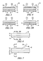
- FIG. 6 is a side view of an embodiment of the present invention. This Figure shows the exposed sleeping surface of the support layer of the sleep system.
- FIG. 7 is a side view of an embodiment of the present invention. Shown therein is the comfort layer bent in an upward position in order to show the first side and second side, both of which are upholstered to provide a comfortable sleeping surface.
- the present invention is a sleeping system that is easily adjustable to different levels of firmness.
- the sleeping system referred to as the system 10
- the sleeping system includes a comfort layer 12 , support layer 14 , and a foundation layer 16 .
- a retailer, wholesaler, or end user may position or reconfigure the three layers in order to customize the sleeping surface.
- the comfort layer 12 is sized for easy rotation, flipping, or removal, as desired.
- the resulting adjustments to the firmness of the system 10 are further discussed below.
- the present invention includes a method of selling the system 10 in which only minimal floor space is required for display.
- the methods disclosed herein allow for selling the systems 10 at various price points depending upon the desire of the consumer.
- the methods disclosed herein allow for the exchange, or replacement, of the comfort layer 12 of the system 10 after the system 10 has been sold so that the end user may experience yet an alternate level of firmness.
- FIG. 1 there is shown an isometric view of the system 10 including a comfort layer 12 positioned on top of a support layer 14 , which is positioned on top of a foundation layer 16 .
- the system 10 may be positioned on a bed frame 18 , or other mount, as known to those of ordinary skill in the art.
- Customization of the system 10 is accomplished by rotating, flipping, or removing the comfort layer 12 . Further customization is accomplished by rotation of the foundation layer 16 .
- the comfort layer 12 and the foundation layer 16 each have multiple firmness sections therein. The line of delineation between the two firmness sections may be along the longitudinal middle of each layer, as best seen in FIGS. 2-5B .
- the boundary of such firmness sections may be according to the needs of a user, as further described in the next paragraph.
- the retailer or end user is altering the firmness of each sleeping position of the system 10 . While the figures represent systems 10 sufficient for sleeping two people, in other embodiments, the system 10 may be constructed for a single person.
- FIG. 2 there is shown a top view of a comfort layer 12 . Shown therein is the first firmness section 20 and second firmness section 22 of the comfort layer 12 .
- the broken line therein is a schematic delineation of the boundaries of the two firmness sections.
- the first firmness section 20 is firm and the second firmness section 22 is plush, or soft.
- the boundaries of the firmness sections may change depending upon the needs of the end user. For example, in certain embodiments, firmness sections may have horizontal boundaries, rather than longitudinal boundaries, in order to create comfort zones for better posture.
- a comfort layer 12 or a foundation layer 16 may have different firmness sections corresponding to different areas of the body, such as the torso or legs.
- a comfort layer 12 , or a foundation layer 16 may have a section therein which is firm and another section therein which is plush, soft or less firm. As further described herein, the comfort layer 12 may be rotated for firmness and flipped for longevity.
- FIGS. 3 , 4 , 5 A and 5 B are cross sectional views of alternate configurations of the three layers within the system.
- the cross-sections, or slices, which result in the views shown in FIGS. 3 and 4 are along the 3 - 3 and 4 - 4 lines shown in FIG. 7 .
- the cross-section which results in the views shown in FIGS. 5A and 5B are along the 5 A- 5 A line and 5 B- 5 B line, respectively, shown in FIG. 6 .
- the hatching shown in FIGS. 3-5B represents various materials of construction, which are described in detail below. The purpose of the hatching is to show that each firmness section is constructed of a different material. Thus, resulting in the different firmness levels.
- reorienting or reconfiguring the comfort layer 12 and the foundation layer 16 results in at least six different firmness levels. Those firmness levels are shown in the hexagon shapes in the Figures and are referred to as firmness levels 1-6, with firmness level one being the most firm and firmness level 6 being the most plush. Stated another way, beneath each hexagon shape is a portion of the system 10 including a foundation layer 16 , support layer 14 and comfort layer 12 which result in the firmness level indicated. As further described below, firmness levels 1 and 2 result from a foundation layer 16 and support layer 14 , without a comfort layer 12 .
- a single system 10 having a foundation layer 16 , support layer 14 , and comfort layer 12 may be oriented or configured to provide the six firmness levels described herein. Even more alternate firmness levels may be accomplished by substituting into a system 10 a layer made of different materials of construction than the layer which it replaces.
- the first firmness section 20 is firm.
- the second firmness section 22 of the comfort layer 12 is plush, or soft.
- the support layer 14 has a consistent firmness such that multiple levels of firmness are not available within the support layer 14 .
- the first firmness section 24 is firm and the second firmness section 26 is plush.
- the relative firmness of the comfort layer 12 and the foundation layer 16 differ due to the function of each within the system 10 . Discussion of materials of construction of each layer is provided below. In the orientation shown in FIG.
- firmness level six the most plush, or soft, is achieved by the combination of the second firmness section 22 of the comfort layer 12 , the support layer 14 , and the second firmness section 26 of the foundation layer 16 .
- the resulting firmness level three is also shown in FIG. 3 , due to the combination of the first firmness section 20 of the comfort layer and the first firmness section 24 of the foundation layer 16 , both of which are firm.
- the first firmness section 24 and the second firmness section 26 of the foundation layer 16 may result from the use of separate foundation units which are placed side by side on a bed frame, as further described in relation to FIG. 5B . In such a configuration, the ability to adjust firmness is still present.
- FIG. 4 there is shown a cross sectional view of the system 10 , which has been reconfigured by rotating or flipping the comfort layer 12 .
- the orientation of the comfort layer 12 has been changed such that the location of the first firmness section 20 of the comfort layer 12 has been reversed with the second firmness section 22 of the comfort layer 12 .
- Firmness level four results from the combination of the first firmness section 24 of the foundation layer 16 and the second firmness section 22 of the comfort layer 12 .
- resulting firmness level five due to the combination of the second firmness section 26 of the foundation layer 16 and the first firmness section 20 of the comfort layer 12 .
- FIG. 5A there is shown an embodiment of the system 10 having a foundation layer 16 having two firmness sections.
- FIG. 5B is a system 10 having two separate foundation layers 16 , each having a different firmness, being placed side by side. Each embodiment shown includes the support layer 14 .
- the comfort layer 12 has been removed from each embodiment of the system 10 .
- firmness level one the most firm level
- Firmness level two results from the combination of the support layer 14 and the second firmness section 26 of the foundation layer 16 .
- firmness level one, the most firm level results from the support layer 14 in combination with the first foundation layer 16 providing firmness section 24 .
- Firmness level two results from the combination of the support layer 14 and the second foundation layer 16 providing firmness section 26 .
- the support layer 14 has a first side 32 .
- the first side 32 of the support layer 14 is constructed of upholstered material such that a sleeping surface is provided. Accordingly, when the comfort layer 12 is removed from the system 10 , the first side 32 is exposed and may be used as a comfortable sleeping surface.
- FIG. 7 there is shown the system 10 in which the comfort layer 12 is bent upward away from the support layer 14 in order to show its flexibility and the first side 28 and the second side 30 .
- the comfort layer 12 is constructed so that both the first side 28 and the second side 30 are sleeping surfaces.
- the comfort layer 12 may be flipped, or rotated, such that either the first side 28 or the second side 30 is facing upward and used for sleeping.
- Each of the comfort layer 12 , support layer 14 , or foundation layer 16 may be selected from a plurality of available firmnesses or mixture of firmnesses. Any of the following examples of each layer may be positioned so that the support layer 14 is on top of the foundation layer 16 and the comfort layer 12 is on top of the support layer 14 , in order to provide a system 10 , as described herein.
- the system 10 may have the dimensions as known to those of ordinary skill in the art, for example, a single bed, double, queen, king, and the like.
- the foundation layer 16 and comfort layer 12 may not have multiple firmness sections on the longitudinal halves of the system 10 for twin size systems 10 , although alternate firmness section positioning, as described above, may apply. That is, in a narrow twin size unit, having multiple firmness sections as shown in FIG. 2 may not be desirable.
- each system 10 includes only one of each layer, and the composition of each layer may be selected from abundant choices.
- the foundation layer 16 may be constructed of material well known to those of ordinary skill in the art, including, wood, steel wire grids, steel coils, polyurethane foam, or the like, and/or any combination thereof.
- the foundation layer 16 may consist of two separate units which are placed side by side, as best seen in FIG. 5B . Accordingly, each foundation layer 16 unit is constructed of certain materials in order to provide a certain firmness.
- each foundation layer 16 unit acts like a either a first firmness section 24 or a second firmness section 26 .
- the foundation layer 16 may be constructed as a single unit having a first firmness section 24 and a second firmness section 26 .
- a foundation layer 16 may have a first firmness section 24 that is constructed of wood and a second firmness section 26 that is constructed of wood and a steel wire grid.
- the foundation layer 16 may, for example, have a first firmness section 24 that is constructed of steel coil springs and a second firmness section 26 that is constructed of wood, a steel wire grid, and padding.
- any of the materials of construction may be mixed and matched to obtain a foundation layer 16 having a firmness section, or multiple firmness sections, so that each firmness section has the specifically desired firmness.
- the foundation layer 16 is then encased within an upholstered covering as known to those of ordinary skill in the art.
- Those of ordinary skill in the art are familiar with the manner of gluing, sewing, or otherwise attaching the various materials in order to construct a unitary foundation layer 16 .
- Those of ordinary skill in the art are also familiar with the manner of constructing each of the various layers of the system 10 disclosed herein.
- U.S. Patents and U.S. Patent application Publications for various beds include U.S.
- the foundation layer 16 may have a height of from about 4 inches to about 12 inches, and is preferably 8-10 inches high.
- the foundation layer 16 is not intended to provide a sleeping surface. Accordingly, such additional padding or preferred fabric associated with a sleeping surface is not present. While only limited examples of the construction of the foundation layer 16 have been described herein, those of ordinary skill in the art will appreciate the large number of differing adjustments which may be made to the disclosure provided herein.
- the support layer 14 may be constructed of material similar to those used in a conventional mattress. Such materials generally including steel inner springs, polyurethane foam, wool, cotton, latex foam, memory foam, and the like, and/or any combination thereof. In certain embodiments, the support layer 14 may include air chambers, bladders, or the like. Such materials are well known in the bedding industry and readily commercially available.
- the support layer 14 has a consistent firmness, or density, and does not have various firmness sections like the foundation layer 16 and the comfort layer 12 .
- the support layer 14 is encased within fabric or other conventional material as known in the bedding industry.
- the first side 32 of the support layer 14 is provided to be a sleeping surface.
- the first side 32 is covered in an upholstered material, as known to those of ordinary skill in the art, in order to provide a comfortable sleeping surface.
- upholstered materials are readily commercially available and well known in the bedding industry.
- Such materials are fixedly secured, as known to those of ordinary skill in the art, to the support layer 14 .
- the support layer 14 has a height of from about 9 inches to about 16 inches. In still other embodiments, the support layer 14 has a height of from about 9 inches to about 12 inches.
- the comfort layer 12 may be constructed of material well known in the bedding industry and readily commercially available, such as gel, latex foam, memory foam, micro-coils, polyurethane foam, and the like, and/or any combination thereof.
- the comfort layer 12 may, for example, have a first firmness section 20 constructed of memory foam and a second firmness section 22 constructed of latex.
- the comfort layer 12 may, for example, have a first firmness section 20 constructed of latex foam and a second firmness section 22 constructed of a mixture of latex foam and memory foam.
- the comfort layer 12 may, for example, have a first firmness section 20 constructed of gel and a second firmness section 22 constructed of latex foam.
- any of the materials of construction may be mixed and matched to obtain a comfort layer 12 having a firmness section, or multiple firmness sections, so that each firmness section has the specifically desired firmness.
- Those of ordinary skill in the art are familiar with gluing, sewing, or otherwise fixedly securing the first firmness section 20 to the second firmness section 22 of the comfort layer 12 .
- Both the first side 28 and the second side 30 of the comfort layer 12 are covered with an upholstered material, or other sleeping surface fabric, so that a user may sleep on either side.
- the comfort layer 12 may have a height of from about 3 inches to about 7 inches. In alternate embodiments, the comfort layer 12 may have a height of from about 4 inches to about 6 inches.
- the sleeping system 10 is easily reconfigured by a person.
- One manner of reconfiguring the system 10 is to remove the comfort layer 12 .
- Another manner of reconfiguring the system 10 is to rotate, or flip, the comfort layer 12 , in order to reverse the positions of the firmness sections therein.
- a person may rotate (not flip) the foundation layer 16 . That said, in practical terms, rotating the foundation layer 16 is really just repositioning the system 10 so that the head of the bed is swapped with the foot of the bed. In alternate embodiments having side by side foundation layer 16 units, a person may reverse the positioning of the side by side foundation layer 16 units.
- the wide range of adjustable bedding which is provided by the present invention has been described herein.
- any of the many foundation layers 16 may be combined with any of the many comfort layers 12 in order to build a bed which provides the desired firmness. Additionally, in certain embodiments, varieties of materials of construction for the support layer 14 allow for selection of a support layer 14 to compliment the foundation layer 16 and comfort layer 12 .
- the method of selling the present system 10 provides the benefit that only a limited number of display systems 10 are needed on retail floor space, rather than a large number of individual beds, each of which offers a different firmness. Because the comfort layer 12 may be easily rotated, flipped, or removed by a single person, all six of the firmness levels of a system 10 may be shown to, and experienced by, a consumer with the use of only a single display system 10 . Further, many comfort layers 12 having alternate firmnesses may be stored near the system 10 for easy substitution with the system 10 . The only reason there would be a need for multiple display systems 10 would be display alternate foundation layers 16 .
- the current system 10 also provides the opportunity to offer different price points of bedding depending on the configuration of the system 10 sold.
- a retailer may offer a system 10 at a reduced price point merely by not including the comfort layer 12 in the sale.
- the retailer may offer bedding at a higher price point by including the comfort layer 12 .
- a retailer, or wholesaler that sold a system 10 may exchange, or replace, the comfort layer 12 of the system 10 without having to replace the remainder of the system 10 .
- the party selling the system 10 generally a retailer or wholesaler, may exchange the comfort layer 12 by mail, or shipping. Those of ordinary skill in the art are familiar with the many types of mailing or shipping which would be appropriate to provide timely transport of comfort layers 12 as described herein.
- a retailer may provide a previous consumer an alternate firmness experience by providing the latest comfort layer 12 for use in combination with the consumer's system 10 , which may have been purchased years before.
- This method of exchanging component parts may be applied to other bedding as well.
Abstract
Description
Claims (17)
Priority Applications (2)
| Application Number | Priority Date | Filing Date | Title |
|---|---|---|---|
| US13/090,331 US9289074B1 (en) | 2011-04-20 | 2011-04-20 | Sleeping system and method for adjusting the same |
| US15/077,790 US20160270548A1 (en) | 2011-04-20 | 2016-03-22 | Adjustable sleeping system |
Applications Claiming Priority (1)
| Application Number | Priority Date | Filing Date | Title |
|---|---|---|---|
| US13/090,331 US9289074B1 (en) | 2011-04-20 | 2011-04-20 | Sleeping system and method for adjusting the same |
Related Child Applications (1)
| Application Number | Title | Priority Date | Filing Date |
|---|---|---|---|
| US15/077,790 Continuation US20160270548A1 (en) | 2011-04-20 | 2016-03-22 | Adjustable sleeping system |
Publications (1)
| Publication Number | Publication Date |
|---|---|
| US9289074B1 true US9289074B1 (en) | 2016-03-22 |
Family
ID=55487224
Family Applications (2)
| Application Number | Title | Priority Date | Filing Date |
|---|---|---|---|
| US13/090,331 Expired - Fee Related US9289074B1 (en) | 2011-04-20 | 2011-04-20 | Sleeping system and method for adjusting the same |
| US15/077,790 Abandoned US20160270548A1 (en) | 2011-04-20 | 2016-03-22 | Adjustable sleeping system |
Family Applications After (1)
| Application Number | Title | Priority Date | Filing Date |
|---|---|---|---|
| US15/077,790 Abandoned US20160270548A1 (en) | 2011-04-20 | 2016-03-22 | Adjustable sleeping system |
Country Status (1)
| Country | Link |
|---|---|
| US (2) | US9289074B1 (en) |
Cited By (3)
| Publication number | Priority date | Publication date | Assignee | Title |
|---|---|---|---|---|
| US20170119168A1 (en) * | 2015-10-30 | 2017-05-04 | Intercoil International Co, LLC | Mattresses with mutilple customizable and replaceable levels and sections and methods thereof |
| US20180035819A1 (en) * | 2016-08-05 | 2018-02-08 | PT Massindo International | Mattress with adjustable hardness and comfort levels |
| US10542825B1 (en) * | 2017-07-12 | 2020-01-28 | Protech, Llc | Multi-zone mattress |
Families Citing this family (1)
| Publication number | Priority date | Publication date | Assignee | Title |
|---|---|---|---|---|
| CN106724369A (en) * | 2016-12-13 | 2017-05-31 | 佛山市顺德区标越家具有限公司 | A kind of mattress with multimode comfort liner |
Citations (51)
| Publication number | Priority date | Publication date | Assignee | Title |
|---|---|---|---|---|
| US2651788A (en) * | 1950-05-09 | 1953-09-15 | Taylor Bedding Mfg Co | Mattress |
| US3521311A (en) * | 1968-03-01 | 1970-07-21 | Paul P Cohen | Mattress |
| US3534417A (en) | 1968-07-08 | 1970-10-20 | Truman C Boyles | Reversible foam mattress having different degrees of firmness |
| US3626523A (en) * | 1970-09-25 | 1971-12-14 | Harry J Robins | Bed foundation and mattress assembly |
| US4040133A (en) | 1976-06-28 | 1977-08-09 | Murvin Bruce Gilreath | Bedding attachment system |
| US4213214A (en) | 1978-12-26 | 1980-07-22 | Gilhooly James E | Multiple firmness multiple sleeper mattress |
| US4458371A (en) | 1981-03-16 | 1984-07-10 | Leggett & Platt, Incorporated | Bed frame with mattress retainer clip |
| US4554692A (en) | 1984-12-13 | 1985-11-26 | Leggett & Platt, Incorporated | Adjustable box spring retainer bracket |
| US4771995A (en) | 1987-04-15 | 1988-09-20 | Leggett & Platt, Incorporated | Collapsible box spring |
| US4862541A (en) | 1988-05-12 | 1989-09-05 | Hutton William B | Device for attaching a sheet to a mattress |
| US4916766A (en) | 1989-08-18 | 1990-04-17 | Grandy Malcolm B | Bed sheet and mattress attachment means |
| US5161276A (en) | 1992-04-10 | 1992-11-10 | Hutton William B | Bed sheet attachment device for a mattress |
| US5182827A (en) | 1991-10-31 | 1993-02-02 | Carrier Odie R | Sheet-mattress retainer |
| US5259079A (en) | 1992-10-26 | 1993-11-09 | Big Sur Waterbeds, Inc. | Double bed arrangement with combination mattress |
| US5471688A (en) * | 1994-02-28 | 1995-12-05 | Cavazos; Frank G. | Modular innerspring and box spring assemblies |
| US5513402A (en) * | 1991-08-20 | 1996-05-07 | Schwartz; Jack | Mattress system |
| US5642547A (en) | 1996-07-12 | 1997-07-01 | Hutton; William B. | Bed sheet attachment device for a mattress, and method |
| US5745940A (en) | 1996-06-18 | 1998-05-05 | Roberts; Derek | Customized modular mattress and bedding |
| US5794285A (en) | 1997-01-30 | 1998-08-18 | Burch; Reda R. | Bed cover assembly |
| US5819340A (en) | 1997-09-15 | 1998-10-13 | Kelly; Jim E. | Infant sleeper |
| US5960496A (en) * | 1998-07-14 | 1999-10-05 | Boyd; Dennis | Mattress system |
| US5970547A (en) * | 1997-04-07 | 1999-10-26 | Cavazos; Frank G. | Modular mattress and innerspring |
| US6101653A (en) | 1999-02-22 | 2000-08-15 | England/Corsair, Inc. | Spilt support configuration mattress |
| US6298510B1 (en) | 1999-09-15 | 2001-10-09 | L&P Property Management Company | Roll packed bedding products |
| US20020062524A1 (en) | 1999-11-29 | 2002-05-30 | Vogland James H. | Mattress and sheet attachment assembly |
| US6481033B2 (en) | 1998-09-25 | 2002-11-19 | Isaac Fogel | Multiple module mattress system with depressions accomodating inserts of differing firmness |
| US20030135930A1 (en) | 2002-01-21 | 2003-07-24 | Varese Emanuele Piccolomini Clementini Adami | Mattress with diversified density |
| US20030140422A1 (en) | 2002-01-29 | 2003-07-31 | Nick Sama | Mattress attachment apparatus |
| US6684425B2 (en) | 2002-02-14 | 2004-02-03 | Edmund Scott Davis | Mattress retainer for adjustable bed |
| US6687935B2 (en) | 1995-11-30 | 2004-02-10 | Hill-Rom Services, Inc. | Mattress structure |
| US6721982B2 (en) | 2002-03-25 | 2004-04-20 | Sealy Technology Llc | Quilt-stitched internal mattress pillows |
| US20050028273A1 (en) | 2001-05-11 | 2005-02-10 | Weedling Robert E. | Patient transfer mattress having connectable segments |
| US7047579B2 (en) | 2004-03-23 | 2006-05-23 | L&P Property Management | Mattress retainer bracket |
| US7104593B2 (en) | 2003-11-14 | 2006-09-12 | Freightliner Llc | Lower bunk for a vehicle |
| US7155765B2 (en) * | 2003-10-14 | 2007-01-02 | Tempur World, Llc | Pillow top for a cushion |
| US7191483B2 (en) * | 2005-06-03 | 2007-03-20 | American Pacific Plastic Fabricators | Composite foam mattress assembly |
| US20070283501A1 (en) | 2006-06-12 | 2007-12-13 | L&P Property Management Company | Modular Bedding System and Method of Assembly |
| US7353550B2 (en) | 2004-09-21 | 2008-04-08 | Antinori Steven J | Retainer system for adjustable beds |
| US20080134431A1 (en) | 2006-12-11 | 2008-06-12 | Boyd Flotation, Inc. | Bed with an Apparatus for Securing an Adjustable Base Support to a Mattress |
| US7386903B2 (en) | 2005-06-03 | 2008-06-17 | American Pacific Plastic Fabricators, Inc. | Composite mattress assembly and method for adjusting the same |
| US20080201856A1 (en) | 2007-02-26 | 2008-08-28 | Howard John Hunter | Mattress system and method |
| US7454810B2 (en) | 2006-06-20 | 2008-11-25 | Wells Thomas J | Divided support mattress |
| US7607181B1 (en) | 2009-01-26 | 2009-10-27 | L & P | Mattress retainer blocks |
| US7661166B1 (en) | 2008-09-18 | 2010-02-16 | Fredman Bros. Furniture Company, Inc. | Adjustable firmness mattress assembly |
| US20100115697A1 (en) | 2008-11-10 | 2010-05-13 | L & P Property Management Company | Mattress with attachment panels for removable attachment to a mattress support |
| US7748066B2 (en) | 2003-09-26 | 2010-07-06 | Dreamwell, Ltd. | Mattress center ridge compensator |
| US20100229309A1 (en) | 2009-03-11 | 2010-09-16 | Aaron Goldsmith | Mattress retainer |
| US7827633B2 (en) | 2008-11-03 | 2010-11-09 | Barbara Taylor | Bed clothing assembly |
| US7930780B2 (en) | 2006-06-29 | 2011-04-26 | Alain Clenet | Adjustable bed frame assembly |
| US20120017370A1 (en) | 2007-10-19 | 2012-01-26 | Zinus Inc. | Edge Attachment for a Mattress Supporting System |
| US20130174348A1 (en) * | 2012-01-06 | 2013-07-11 | Jon Stowe | Dual Sided Comfort Sleep System |
-
2011
- 2011-04-20 US US13/090,331 patent/US9289074B1/en not_active Expired - Fee Related
-
2016
- 2016-03-22 US US15/077,790 patent/US20160270548A1/en not_active Abandoned
Patent Citations (53)
| Publication number | Priority date | Publication date | Assignee | Title |
|---|---|---|---|---|
| US2651788A (en) * | 1950-05-09 | 1953-09-15 | Taylor Bedding Mfg Co | Mattress |
| US3521311A (en) * | 1968-03-01 | 1970-07-21 | Paul P Cohen | Mattress |
| US3534417A (en) | 1968-07-08 | 1970-10-20 | Truman C Boyles | Reversible foam mattress having different degrees of firmness |
| US3626523A (en) * | 1970-09-25 | 1971-12-14 | Harry J Robins | Bed foundation and mattress assembly |
| US4040133A (en) | 1976-06-28 | 1977-08-09 | Murvin Bruce Gilreath | Bedding attachment system |
| US4213214A (en) | 1978-12-26 | 1980-07-22 | Gilhooly James E | Multiple firmness multiple sleeper mattress |
| US4458371A (en) | 1981-03-16 | 1984-07-10 | Leggett & Platt, Incorporated | Bed frame with mattress retainer clip |
| US4554692A (en) | 1984-12-13 | 1985-11-26 | Leggett & Platt, Incorporated | Adjustable box spring retainer bracket |
| US4771995A (en) | 1987-04-15 | 1988-09-20 | Leggett & Platt, Incorporated | Collapsible box spring |
| US4862541A (en) | 1988-05-12 | 1989-09-05 | Hutton William B | Device for attaching a sheet to a mattress |
| US4916766A (en) | 1989-08-18 | 1990-04-17 | Grandy Malcolm B | Bed sheet and mattress attachment means |
| US5513402A (en) * | 1991-08-20 | 1996-05-07 | Schwartz; Jack | Mattress system |
| US5819349A (en) | 1991-08-20 | 1998-10-13 | Schwartz; Jack | Mattress |
| US5182827A (en) | 1991-10-31 | 1993-02-02 | Carrier Odie R | Sheet-mattress retainer |
| US5161276A (en) | 1992-04-10 | 1992-11-10 | Hutton William B | Bed sheet attachment device for a mattress |
| US5259079A (en) | 1992-10-26 | 1993-11-09 | Big Sur Waterbeds, Inc. | Double bed arrangement with combination mattress |
| US5471688A (en) * | 1994-02-28 | 1995-12-05 | Cavazos; Frank G. | Modular innerspring and box spring assemblies |
| US6687935B2 (en) | 1995-11-30 | 2004-02-10 | Hill-Rom Services, Inc. | Mattress structure |
| US5745940A (en) | 1996-06-18 | 1998-05-05 | Roberts; Derek | Customized modular mattress and bedding |
| US5642547A (en) | 1996-07-12 | 1997-07-01 | Hutton; William B. | Bed sheet attachment device for a mattress, and method |
| US5794285A (en) | 1997-01-30 | 1998-08-18 | Burch; Reda R. | Bed cover assembly |
| US5970547A (en) * | 1997-04-07 | 1999-10-26 | Cavazos; Frank G. | Modular mattress and innerspring |
| US5819340A (en) | 1997-09-15 | 1998-10-13 | Kelly; Jim E. | Infant sleeper |
| US5960496A (en) * | 1998-07-14 | 1999-10-05 | Boyd; Dennis | Mattress system |
| US6481033B2 (en) | 1998-09-25 | 2002-11-19 | Isaac Fogel | Multiple module mattress system with depressions accomodating inserts of differing firmness |
| US6101653A (en) | 1999-02-22 | 2000-08-15 | England/Corsair, Inc. | Spilt support configuration mattress |
| US6298510B1 (en) | 1999-09-15 | 2001-10-09 | L&P Property Management Company | Roll packed bedding products |
| US20020062524A1 (en) | 1999-11-29 | 2002-05-30 | Vogland James H. | Mattress and sheet attachment assembly |
| US20050028273A1 (en) | 2001-05-11 | 2005-02-10 | Weedling Robert E. | Patient transfer mattress having connectable segments |
| US20030135930A1 (en) | 2002-01-21 | 2003-07-24 | Varese Emanuele Piccolomini Clementini Adami | Mattress with diversified density |
| US20030140422A1 (en) | 2002-01-29 | 2003-07-31 | Nick Sama | Mattress attachment apparatus |
| US6684425B2 (en) | 2002-02-14 | 2004-02-03 | Edmund Scott Davis | Mattress retainer for adjustable bed |
| US6721982B2 (en) | 2002-03-25 | 2004-04-20 | Sealy Technology Llc | Quilt-stitched internal mattress pillows |
| US7748066B2 (en) | 2003-09-26 | 2010-07-06 | Dreamwell, Ltd. | Mattress center ridge compensator |
| US7155765B2 (en) * | 2003-10-14 | 2007-01-02 | Tempur World, Llc | Pillow top for a cushion |
| US7104593B2 (en) | 2003-11-14 | 2006-09-12 | Freightliner Llc | Lower bunk for a vehicle |
| US7047579B2 (en) | 2004-03-23 | 2006-05-23 | L&P Property Management | Mattress retainer bracket |
| US7353550B2 (en) | 2004-09-21 | 2008-04-08 | Antinori Steven J | Retainer system for adjustable beds |
| US7386903B2 (en) | 2005-06-03 | 2008-06-17 | American Pacific Plastic Fabricators, Inc. | Composite mattress assembly and method for adjusting the same |
| US7191483B2 (en) * | 2005-06-03 | 2007-03-20 | American Pacific Plastic Fabricators | Composite foam mattress assembly |
| US20070283501A1 (en) | 2006-06-12 | 2007-12-13 | L&P Property Management Company | Modular Bedding System and Method of Assembly |
| US7454810B2 (en) | 2006-06-20 | 2008-11-25 | Wells Thomas J | Divided support mattress |
| US7930780B2 (en) | 2006-06-29 | 2011-04-26 | Alain Clenet | Adjustable bed frame assembly |
| US20080134431A1 (en) | 2006-12-11 | 2008-06-12 | Boyd Flotation, Inc. | Bed with an Apparatus for Securing an Adjustable Base Support to a Mattress |
| US20080201856A1 (en) | 2007-02-26 | 2008-08-28 | Howard John Hunter | Mattress system and method |
| US8117700B2 (en) * | 2007-02-26 | 2012-02-21 | Howard John Hunter | Mattress system and method |
| US20120017370A1 (en) | 2007-10-19 | 2012-01-26 | Zinus Inc. | Edge Attachment for a Mattress Supporting System |
| US7661166B1 (en) | 2008-09-18 | 2010-02-16 | Fredman Bros. Furniture Company, Inc. | Adjustable firmness mattress assembly |
| US7827633B2 (en) | 2008-11-03 | 2010-11-09 | Barbara Taylor | Bed clothing assembly |
| US20100115697A1 (en) | 2008-11-10 | 2010-05-13 | L & P Property Management Company | Mattress with attachment panels for removable attachment to a mattress support |
| US7607181B1 (en) | 2009-01-26 | 2009-10-27 | L & P | Mattress retainer blocks |
| US20100229309A1 (en) | 2009-03-11 | 2010-09-16 | Aaron Goldsmith | Mattress retainer |
| US20130174348A1 (en) * | 2012-01-06 | 2013-07-11 | Jon Stowe | Dual Sided Comfort Sleep System |
Non-Patent Citations (1)
| Title |
|---|
| "Unity-Half Soft and Half Firm Mattress by Essentia", Essentia, Quebec, Canada-http://www.myessentia.com/product-info.php?unity-pid8.html; Feb. 24, 2011. |
Cited By (4)
| Publication number | Priority date | Publication date | Assignee | Title |
|---|---|---|---|---|
| US20170119168A1 (en) * | 2015-10-30 | 2017-05-04 | Intercoil International Co, LLC | Mattresses with mutilple customizable and replaceable levels and sections and methods thereof |
| US20210161302A1 (en) * | 2015-10-30 | 2021-06-03 | Intercoil International Co, LLC | Mattresses with multiple customizable and replaceable levels and sections and methods thereof |
| US20180035819A1 (en) * | 2016-08-05 | 2018-02-08 | PT Massindo International | Mattress with adjustable hardness and comfort levels |
| US10542825B1 (en) * | 2017-07-12 | 2020-01-28 | Protech, Llc | Multi-zone mattress |
Also Published As
| Publication number | Publication date |
|---|---|
| US20160270548A1 (en) | 2016-09-22 |
Similar Documents
| Publication | Publication Date | Title |
|---|---|---|
| US11019936B2 (en) | Pocketed foam systems and methods | |
| US10368655B2 (en) | Mattress | |
| US20070283501A1 (en) | Modular Bedding System and Method of Assembly | |
| US9949571B2 (en) | Spring unit for a mattress | |
| US7386903B2 (en) | Composite mattress assembly and method for adjusting the same | |
| US20160270548A1 (en) | Adjustable sleeping system | |
| US7191483B2 (en) | Composite foam mattress assembly | |
| AU695946B2 (en) | Multiple firmness mattress | |
| EP3666127B1 (en) | Mattress | |
| US9867475B2 (en) | Mattress structure, mattress system and method for using a mattress | |
| US20040172767A1 (en) | Posturized pocketed bedding or seating product having pockets of differing heights | |
| US10617224B2 (en) | Mattress | |
| CA2801789A1 (en) | Modular component mattress | |
| US20190038043A1 (en) | Dual density systems and methods for bedding applications | |
| US11324334B2 (en) | Mattress | |
| AU2016303392A1 (en) | Customizable mattress | |
| US20170156507A1 (en) | Mattress Assembly | |
| CA3171155A1 (en) | Apparatus for convertible and selectable mattress firmness | |
| US20040163180A1 (en) | Compressible encasement tray for bedding and method for selectively modifying bedding product with such a tray | |
| US20070204408A1 (en) | Bedding system with replaceable comfort layer |
Legal Events
| Date | Code | Title | Description |
|---|---|---|---|
| AS | Assignment |
Owner name: SOUTHERLAND, INC., TENNESSEE Free format text: ASSIGNMENT OF ASSIGNORS INTEREST;ASSIGNORS:CORBIN, DAVID R.;RUSSO, STEPHEN S.;SIGNING DATES FROM 20110726 TO 20110727;REEL/FRAME:026744/0652 |
|
| AS | Assignment |
Owner name: PNC BANK, NATIONAL ASSOCIATION, PENNSYLVANIA Free format text: SECURITY AGREEMENT;ASSIGNOR:SOUTHERLAND, INC.;REEL/FRAME:027450/0047 Effective date: 20111223 |
|
| STCF | Information on status: patent grant |
Free format text: PATENTED CASE |
|
| FEPP | Fee payment procedure |
Free format text: MAINTENANCE FEE REMINDER MAILED (ORIGINAL EVENT CODE: REM.); ENTITY STATUS OF PATENT OWNER: LARGE ENTITY |
|
| LAPS | Lapse for failure to pay maintenance fees |
Free format text: PATENT EXPIRED FOR FAILURE TO PAY MAINTENANCE FEES (ORIGINAL EVENT CODE: EXP.); ENTITY STATUS OF PATENT OWNER: LARGE ENTITY |
|
| STCH | Information on status: patent discontinuation |
Free format text: PATENT EXPIRED DUE TO NONPAYMENT OF MAINTENANCE FEES UNDER 37 CFR 1.362 |
|
| FP | Lapsed due to failure to pay maintenance fee |
Effective date: 20200322 |
|
| PRDP | Patent reinstated due to the acceptance of a late maintenance fee |
Effective date: 20210203 |
|
| FEPP | Fee payment procedure |
Free format text: SURCHARGE, PETITION TO ACCEPT PYMT AFTER EXP, UNINTENTIONAL (ORIGINAL EVENT CODE: M1558); ENTITY STATUS OF PATENT OWNER: LARGE ENTITY Free format text: PETITION RELATED TO MAINTENANCE FEES GRANTED (ORIGINAL EVENT CODE: PMFG); ENTITY STATUS OF PATENT OWNER: LARGE ENTITY Free format text: PETITION RELATED TO MAINTENANCE FEES FILED (ORIGINAL EVENT CODE: PMFP); ENTITY STATUS OF PATENT OWNER: LARGE ENTITY |
|
| MAFP | Maintenance fee payment |
Free format text: PAYMENT OF MAINTENANCE FEE, 4TH YEAR, LARGE ENTITY (ORIGINAL EVENT CODE: M1551); ENTITY STATUS OF PATENT OWNER: LARGE ENTITY Year of fee payment: 4 |
|
| STCF | Information on status: patent grant |
Free format text: PATENTED CASE |
|
| AS | Assignment |
Owner name: MIDCAP BUSINESS CREDIT LLC, CONNECTICUT Free format text: SECURITY INTEREST;ASSIGNOR:SOUTHERLAND, INC.;REEL/FRAME:062790/0325 Effective date: 20230215 Owner name: SOUTHERLAND, INC., TENNESSEE Free format text: RELEASE BY SECURED PARTY;ASSIGNOR:PNC BANK, NATIONAL ASSOCIATION;REEL/FRAME:062790/0253 Effective date: 20230215 |
|
| FEPP | Fee payment procedure |
Free format text: MAINTENANCE FEE REMINDER MAILED (ORIGINAL EVENT CODE: REM.); ENTITY STATUS OF PATENT OWNER: LARGE ENTITY |