US9282949B2 - Charging station for battery powered biopsy apparatus - Google Patents
Charging station for battery powered biopsy apparatus Download PDFInfo
- Publication number
- US9282949B2 US9282949B2 US13/630,851 US201213630851A US9282949B2 US 9282949 B2 US9282949 B2 US 9282949B2 US 201213630851 A US201213630851 A US 201213630851A US 9282949 B2 US9282949 B2 US 9282949B2
- Authority
- US
- United States
- Prior art keywords
- driver assembly
- housing
- assembly
- charging
- charging station
- Prior art date
- Legal status (The legal status is an assumption and is not a legal conclusion. Google has not performed a legal analysis and makes no representation as to the accuracy of the status listed.)
- Active, expires
Links
Images


Classifications
-
- A—HUMAN NECESSITIES
- A61—MEDICAL OR VETERINARY SCIENCE; HYGIENE
- A61B—DIAGNOSIS; SURGERY; IDENTIFICATION
- A61B10/00—Other methods or instruments for diagnosis, e.g. instruments for taking a cell sample, for biopsy, for vaccination diagnosis; Sex determination; Ovulation-period determination; Throat striking implements
- A61B10/02—Instruments for taking cell samples or for biopsy
- A61B10/0233—Pointed or sharp biopsy instruments
- A61B10/0283—Pointed or sharp biopsy instruments with vacuum aspiration, e.g. caused by retractable plunger or by connected syringe
-
- A—HUMAN NECESSITIES
- A61—MEDICAL OR VETERINARY SCIENCE; HYGIENE
- A61B—DIAGNOSIS; SURGERY; IDENTIFICATION
- A61B10/00—Other methods or instruments for diagnosis, e.g. instruments for taking a cell sample, for biopsy, for vaccination diagnosis; Sex determination; Ovulation-period determination; Throat striking implements
- A61B10/02—Instruments for taking cell samples or for biopsy
- A61B10/0233—Pointed or sharp biopsy instruments
- A61B10/0266—Pointed or sharp biopsy instruments means for severing sample
- A61B10/0275—Pointed or sharp biopsy instruments means for severing sample with sample notch, e.g. on the side of inner stylet
-
- A—HUMAN NECESSITIES
- A61—MEDICAL OR VETERINARY SCIENCE; HYGIENE
- A61B—DIAGNOSIS; SURGERY; IDENTIFICATION
- A61B10/00—Other methods or instruments for diagnosis, e.g. instruments for taking a cell sample, for biopsy, for vaccination diagnosis; Sex determination; Ovulation-period determination; Throat striking implements
- A61B10/02—Instruments for taking cell samples or for biopsy
- A61B2010/0208—Biopsy devices with actuators, e.g. with triggered spring mechanisms
-
- A—HUMAN NECESSITIES
- A61—MEDICAL OR VETERINARY SCIENCE; HYGIENE
- A61B—DIAGNOSIS; SURGERY; IDENTIFICATION
- A61B17/00—Surgical instruments, devices or methods, e.g. tourniquets
- A61B2017/00367—Details of actuation of instruments, e.g. relations between pushing buttons, or the like, and activation of the tool, working tip, or the like
- A61B2017/00398—Details of actuation of instruments, e.g. relations between pushing buttons, or the like, and activation of the tool, working tip, or the like using powered actuators, e.g. stepper motors, solenoids
-
- A—HUMAN NECESSITIES
- A61—MEDICAL OR VETERINARY SCIENCE; HYGIENE
- A61B—DIAGNOSIS; SURGERY; IDENTIFICATION
- A61B17/00—Surgical instruments, devices or methods, e.g. tourniquets
- A61B2017/0042—Surgical instruments, devices or methods, e.g. tourniquets with special provisions for gripping
- A61B2017/00424—Surgical instruments, devices or methods, e.g. tourniquets with special provisions for gripping ergonomic, e.g. fitting in fist
-
- A—HUMAN NECESSITIES
- A61—MEDICAL OR VETERINARY SCIENCE; HYGIENE
- A61B—DIAGNOSIS; SURGERY; IDENTIFICATION
- A61B17/00—Surgical instruments, devices or methods, e.g. tourniquets
- A61B2017/0046—Surgical instruments, devices or methods, e.g. tourniquets with a releasable handle; with handle and operating part separable
-
- A—HUMAN NECESSITIES
- A61—MEDICAL OR VETERINARY SCIENCE; HYGIENE
- A61B—DIAGNOSIS; SURGERY; IDENTIFICATION
- A61B17/00—Surgical instruments, devices or methods, e.g. tourniquets
- A61B2017/00477—Coupling
-
- A—HUMAN NECESSITIES
- A61—MEDICAL OR VETERINARY SCIENCE; HYGIENE
- A61B—DIAGNOSIS; SURGERY; IDENTIFICATION
- A61B17/00—Surgical instruments, devices or methods, e.g. tourniquets
- A61B2017/00681—Aspects not otherwise provided for
- A61B2017/00734—Aspects not otherwise provided for battery operated
-
- H—ELECTRICITY
- H02—GENERATION; CONVERSION OR DISTRIBUTION OF ELECTRIC POWER
- H02J—CIRCUIT ARRANGEMENTS OR SYSTEMS FOR SUPPLYING OR DISTRIBUTING ELECTRIC POWER; SYSTEMS FOR STORING ELECTRIC ENERGY
- H02J2310/00—The network for supplying or distributing electric power characterised by its spatial reach or by the load
- H02J2310/10—The network having a local or delimited stationary reach
- H02J2310/20—The network being internal to a load
- H02J2310/23—The load being a medical device, a medical implant, or a life supporting device
-
- H—ELECTRICITY
- H02—GENERATION; CONVERSION OR DISTRIBUTION OF ELECTRIC POWER
- H02J—CIRCUIT ARRANGEMENTS OR SYSTEMS FOR SUPPLYING OR DISTRIBUTING ELECTRIC POWER; SYSTEMS FOR STORING ELECTRIC ENERGY
- H02J7/00—Circuit arrangements for charging or depolarising batteries or for supplying loads from batteries
- H02J7/0042—Circuit arrangements for charging or depolarising batteries or for supplying loads from batteries characterised by the mechanical construction
- H02J7/0044—Circuit arrangements for charging or depolarising batteries or for supplying loads from batteries characterised by the mechanical construction specially adapted for holding portable devices containing batteries
Definitions
- the present invention relates to a biopsy apparatus, and, more particularly, to a charging station for a battery powered biopsy apparatus.
- a biopsy may be performed on a patient to help in determining whether the cells in a biopsied region are cancerous.
- One type of vacuum assisted biopsy apparatus includes a hand-held driver assembly having a vacuum source, and a disposable biopsy probe assembly configured for releasable attachment to the driver assembly.
- One biopsy technique used to evaluate breast tissue involves inserting a biopsy probe into the breast tissue region of interest to capture one or more tissue samples from the region.
- the biopsy probe typically includes a biopsy cannula, e.g., a needle, having a cylindrical side wall defining a lumen, and having a side sample notch located near the distal end that extends though the side wall to the lumen.
- a cutting cannula is positioned coaxial with the biopsy cannula to selectively open and close the sample notch. Vacuum is applied to the lumen, and in turn to the sample notch, for receiving the tissue to be sampled when the sample notch is opened, after which the sample notch is closed by the cutting cannula to sever the tissue, and the severed tissue is transported by vacuum out of the lumen and collected.
- One type of hand-held driver assembly is battery powered, which requires occasional charging to keep the biopsy apparatus operational.
- the present invention provides a charging station for a battery powered biopsy apparatus.
- first and second preceding an element name, e.g., first housing, second housing, third housing, etc., are for identification purposes to distinguish between different elements having similar characteristic, and are not intended to necessarily imply order, unless otherwise specified, nor are the terms “first” and “second” intended to preclude the inclusion of additional similar elements.
- the invention in one form thereof, is directed to a charging station for a battery powered biopsy apparatus.
- the biopsy apparatus includes a driver assembly configured for releasable attachment to a biopsy probe assembly.
- the driver assembly has a battery and a first housing configured to be grasped by a user.
- the first housing has a first cavity.
- the first cavity of the driver assembly is configured for receiving a second housing of the biopsy probe assembly when the biopsy probe assembly is mounted to the driver assembly.
- the second housing has a first shape.
- the charging station includes a charging dock having a third housing and a charging unit contained in the third housing.
- the charging unit has a set of electrical contacts.
- the third housing has a second shape.
- the third housing is received in the first cavity of the driver assembly with the electrical contacts being coupled in electrical communication with the driver assembly when the driver assembly is mounted on the charging dock for charging.
- the charging unit provides a signal to the driver assembly to reset the driver assembly to an initialized state when the driver assembly is mounted to the charging station.
- the invention in another form thereof, is directed to a biopsy system, including a driver assembly, a biopsy probe assembly, and a charging dock.
- the driver assembly has an electromechanical power source with a battery and has a first housing configured to be grasped by a user.
- the first housing has a first cavity.
- the biopsy probe assembly is configured for releasable attachment to the driver assembly.
- the biopsy probe assembly has a frame, a biopsy probe, a transmission device and a second housing.
- the biopsy probe and the second housing are mounted to the frame.
- the second housing contains at least a portion of the transmission device with the biopsy probe being drivably coupled to the transmission device.
- the transmission device is configured for releasable driven coupling to the electromechanical power source of the driver assembly.
- the first cavity of the driver assembly is configured for receiving the second housing of the biopsy probe assembly when the driver assembly is mounted to the biopsy probe assembly.
- the second housing has a first shape.
- the charging dock has a third housing and a charging unit contained in the third housing.
- the charging unit has a set of electrical contacts.
- the third housing has a second shape substantially the same as the first shape of the second housing of the biopsy probe assembly. The third housing is received in the first cavity of the driver assembly with the electrical contacts being coupled in electrical communication with the driver assembly when the driver assembly is mounted on the charging dock for charging.
- the invention in another form thereof, is directed to a method for charging a battery operated biopsy apparatus.
- the method includes providing a signal to a driver assembly of the battery operated biopsy apparatus indicating that a connection between first electrical contacts of a charging unit of a charging station and second electrical contacts of the driver assembly has been made; upon receiving the signal, determining whether the driver assembly is in an error state, wherein if the error state exists, then resetting the driver assembly to an initialized state; and charging a battery of the driver assembly.
- FIG. 1 is a perspective view of a biopsy apparatus, configured in accordance with an embodiment of the present invention, with a disposable biopsy probe mounted to a driver assembly;
- FIG. 2 is a perspective view of a biopsy apparatus of FIG. 1 , with the disposable biopsy probe detached from the driver assembly;
- FIG. 3 is a schematic representation of the biopsy apparatus of FIG. 1 ;
- FIG. 4A is a perspective view of a vacuum seal element of the vacuum path of the driver assembly of FIG. 3 ;
- FIG. 4B is a perspective view of a vacuum seal element of the vacuum path of the disposable biopsy probe of FIG. 3 ;
- FIG. 5A is a perspective view of the fluid management tank of the disposable biopsy probe shown in FIGS. 2 and 3 , with a portion broken away to expose a filter arrangement;
- FIG. 5B is an exploded view of a plurality of fluid absorption layers of the filter arrangement of FIG. 5A ;
- FIG. 5C is a perspective view of a porous filter element of the filter arrangement of FIG. 5A .
- FIG. 6 is a side view of the disposable biopsy probe of FIG. 2 showing in further detail a tissue sample retrieval mechanism with the sample collection tank removed;
- FIG. 7 is a side view of the disposable biopsy probe of FIG. 6 showing the tissue sample retrieval mechanism with the sample collection tank installed, and with the sample collection tank in the raised position;
- FIG. 8 is a side view of the disposable biopsy probe of FIG. 6 showing the tissue sample retrieval mechanism with the sample collection tank installed, and with the sample collection tank in the lowered collection position;
- FIG. 9 is a side view of a portion of the tissue sample retrieval mechanism of FIG. 8 with a portion of the cutter cannula sectioned away to expose the retracting sample basket, and with a portion of the sample basket broken way to show the interaction of the tissue sample scoop of the sample collection tank with the sample notch;
- FIG. 10 is an enlarged front view of the sample collection tank of FIG. 9 showing the interaction of the rim of the sample collection tank with the sample basket shown in section along line 10 - 10 of FIG. 9 ;
- FIG. 11 is a top view of tank positioning mechanism of FIG. 8 ;
- FIG. 12 is a top view of the sample basket and the lift member of the disposable biopsy probe of FIG. 7 , with a portion of lift member broken away to expose a T-shaped stop, and a leaf spring tongue forming a portion of the T-shaped stop for removing residual tissue material and debris from a vacuum path at the sample notch of the sample basket;
- FIG. 13 is a side view of the disposable biopsy probe of FIG. 7 showing the latch member of the tank positioning mechanism in the latched transport position;
- FIG. 14 is a perspective view of a charging station for use in charging the battery contained in the driver assembly of FIGS. 1 and 2 ;
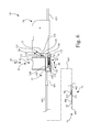
- FIG. 15 is a side view of the charging station of FIG. 14 with the driver assembly shown in phantom lines in an installed position;
- FIG. 16 is an exploded view of the charging station of FIG. 14 ;
- FIG. 17 is an opposite side view of the charging dock of the charging station of FIG. 14 ;
- FIG. 18 is a bottom view of a portion of the housing of the driver assembly of FIG. 1 ;
- FIG. 19 is a bottom perspective view of the charging dock of FIG. 17 with a removable cover removed;
- FIG. 20 is a bottom perspective view of the charging dock of FIG. 17 with the removable cover installed on the charging dock;
- FIG. 21A is a side perspective view of the removable cover of FIG. 20 mounting the electronic components of the charging unit;
- FIG. 21B is a side perspective view of the removable cover opposite to that of FIG. 21A ;
- FIG. 21C is a diagrammatic representation of a power unit suitable for use with the charging unit of FIGS. 21A and 21B ;
- FIG. 22 is a block diagram of a control system associated with the driver assembly of FIGS. 1 and 2 , and the charging station of FIG. 14 ;
- FIG. 23 is a flowchart of a method for charging a battery operated biopsy apparatus in accordance with an embodiment of the present invention.
- a biopsy apparatus 10 which generally includes a non-invasive, e.g., non-disposable, driver assembly 12 and a disposable biopsy probe assembly 14 .
- driver assembly 12 and disposable biopsy probe assembly 14 collectively include a fluid management system 16 that includes a vacuum source 18 , first vacuum path 20 and a second vacuum path 22 .
- Vacuum source 18 and a first vacuum path 20 are permanently associated with driver assembly 12
- a second vacuum path 22 is permanently associated with disposable biopsy probe assembly 14 , as more fully described below, to help facilitate the safe and effective collection of a biopsy tissue sample.
- non-disposable is used to refer to a device that is intended for use on multiple patients during the lifetime of the device
- the term “disposable” is used to refer to a device that is intended to be disposed of after use on a single patient.
- vacuum path means a fluid passageway used to facilitate a vacuum between two points, the fluid passageway passing through one or more components, such as for example, one or more of tubing, conduits, couplers, and interposed devices.
- permanently associated means a connection that is not intended for releasable attachment on a routine basis during the lifetime of the components.
- driver assembly 12 including vacuum source 18 and first vacuum path 20 is reusable as a unit in its entirety
- disposable biopsy probe assembly 14 and second vacuum path 22 are disposable as a unit in its entirety.
- Driver assembly 12 includes a housing 24 configured, and ergonomically designed, to be grasped by a user.
- Driver assembly 12 includes (contained within housing 24 ) vacuum source 18 , first vacuum path 20 , a controller 26 , an electromechanical power source 28 , and a vacuum monitoring mechanism 30 .
- a user interface 32 is located to be mounted to, and externally accessible with respect to, housing 24 .
- Housing 24 defines an elongate cavity 241 which is configured for receiving a corresponding housing 57 of biopsy probe assembly 14 when driver assembly 12 is mounted to biopsy probe assembly 14 .
- Controller 26 is communicatively coupled to electromechanical power source 28 , vacuum source 18 , user interface 32 , and vacuum monitoring mechanism 30 .
- Controller 26 may include, for example, a microprocessor and associated memory for executing program instructions to perform functions associated with the retrieval of biopsy tissue samples, such as controlling one or more components of vacuum source 18 and electromechanical power source 28 .
- Controller 26 also may execute program instructions to monitor one or more conditions and/or positions of components of biopsy apparatus 10 , and to monitor the status of fluid management system 16 associated with driver assembly 12 and biopsy probe assembly 14 .
- the user interface 32 includes control buttons 321 and visual indicators 322 , with control buttons 321 providing user control over various functions of biopsy apparatus 10 , and visual indicators 322 providing visual feedback of the status of one or more conditions and/or positions of components of biopsy apparatus 10 .
- the electromechanical power source 28 may include, for example, an electrical energy source, e.g., battery, 34 and an electrical drive assembly 36 .
- Battery 34 may be, for example, a rechargeable battery. Battery 34 provides electrical power to all electrically powered components in biopsy apparatus 10 , and thus for simplicity in the drawings, such electrical couplings are not shown.
- battery 34 is electrically coupled to vacuum source 18 , controller 26 , user interface 32 and electrical drive assembly 36 .
- electrical drive assembly 36 includes a first drive 361 and a second drive 362 , each being respectively coupled to battery 34 , and each of first drive 361 and second drive 362 respectively electrically and controllably coupled to user interface 32 .
- First drive 361 may include an electrical motor 381 and a motion transfer unit 401 (shown schematically by a line).
- Second drive 362 may include an electrical motor 382 and a motion transfer unit 402 (shown schematically by a line).
- Each electrical motor 381 , 382 may be, for example, a direct current (DC) motor, stepper motor, etc.
- Motion transfer unit 401 of first drive 361 may be configured, for example, with a rotational-to-linear motion converter, such as a worm gear arrangement, rack and pinion arrangement, solenoid-slide arrangement, etc.
- Motion transfer unit 402 of second drive 362 may be configured to transmit rotary motion.
- Each of first drive 361 and second drive 362 may include one or more of a gear, gear train, belt/pulley arrangement, etc.
- Vacuum source 18 is electrically coupled to battery 34 , and has a vacuum source port 181 for establishing a vacuum. Vacuum source 18 is electrically and controllably coupled to user interface 32 . Vacuum source 18 may further include, for example, a vacuum pump 182 driven by an electric motor 183 . Vacuum pump 182 may be, for example, a peristaltic pump, a diaphragm pump, syringe-type pump, etc.
- First vacuum path 20 of driver assembly 12 is permanently associated with vacuum source 18 .
- First vacuum path 20 also sometimes referred to as a non-disposable vacuum path, has a proximal end 201 and a distal end 202 , and includes, for example, conduits 203 , a first one-way valve 204 , and a particulate filter 205 .
- Proximal end 201 is fixedly coupled to vacuum source 18 in fluid communication therewith, e.g., is fixedly connected to vacuum source port 181 of vacuum source 18 .
- distal end 202 includes a first vacuum seal element 206 .
- first vacuum seal element 206 is a planar abutment surface that surrounds a first passageway 207 of first vacuum path 20 .
- First one-way valve 204 is configured and arranged to permit a negative pressure fluid flow toward vacuum source 18 and to prevent a positive pressure fluid flow away from vacuum source 18 toward the distal end 202 of first vacuum path 20 .
- the first one-way valve 204 may be, for example, a check-valve, such as a ball valve or reed valve, that opens with a fluid flow toward vacuum source 18 , and closes in the case of a reverse (positive) flow away from vacuum source 18 .
- particulate filter 205 is located between vacuum source 18 and distal end 202 of first vacuum path 20 .
- Particulate filter 205 may be, for example, a mesh screen formed from metal or plastic. However, it is contemplated that particulate filter 205 may be located in fluid management system 16 between vacuum source 18 and a vacuum receiving component of biopsy probe assembly 14 .
- the vacuum monitoring mechanism 30 is coupled to vacuum source 18 to shut off vacuum source 18 when a sensed vacuum level has fallen below a threshold level.
- Vacuum monitoring mechanism 30 may include, for example, a vacuum monitor and control program executing on controller 26 , and a pressure sensor 301 coupled to controller 26 , and in fluid communication with first vacuum path 20 for detecting a pressure in first vacuum path 20 . If, for example, the vacuum flow level in first vacuum path 20 falls below a predetermined level, indicating a restriction in fluid management system 16 , controller 26 may respond by shutting off vacuum source 18 , e.g., turning off electric motor 183 .
- controller 26 may monitor the current supplied to electric motor 183 , and if the current exceeds a predetermined amount, indicating a restriction in fluid management system 16 , controller 26 may respond by shutting off vacuum source 18 , e.g., turning off electric motor 183 .
- the disposable biopsy probe assembly 14 is configured for releasable attachment to driver assembly 12 .
- releasable attachment means a configuration that facilitates an intended temporary connection followed by selective detachment involving a manipulation of disposable biopsy probe assembly 14 relative to driver assembly 12 , without the need for tools.
- the disposable biopsy probe assembly 14 includes a frame 141 to which a transmission device 42 , a biopsy probe 44 , and the second vacuum path 22 are mounted.
- Biopsy probe 44 is drivably coupled to transmission device 42
- transmission device 42 is drivably coupled to electromechanical power source 28 of driver assembly 12 .
- transmission device 42 includes a first driven unit 421 and a second driven unit 422 that are drivably engaged with various components of biopsy probe 44 .
- first driven unit 421 is drivably engaged with first drive 361 of electrical drive assembly 36 of driver assembly 12 .
- Second driven unit 422 is drivably engaged with second drive 362 of electrical drive assembly 36 of driver assembly 12 .
- biopsy probe 44 includes a sample basket 441 and a cutter cannula 442 .
- Sample basket 441 has a sharpened tip 443 to aid in puncturing tissue and has a sample notch 444 in the form of a recessed region for receiving a biopsy tissue sample.
- Sample basket 441 and a cutter cannula 442 are configured to be individually movable along a longitudinal axis 445 .
- cutter cannula 442 is linearly driven by first driven unit 421 to traverse over sample notch 444 of sample basket 441 along longitudinal axis 445 .
- first driven unit 421 may be in the form of a linear slide that is drivably engaged with first drive 361 of driver assembly 12 , which in turn drives cutter cannula 442 along longitudinal axis 445 in a first direction 46 , i.e., toward a proximal end of driver assembly 12 , to expose sample notch 444 of sample basket 441 , and drives cutter cannula 442 in a second direction 48 opposite to first direction 46 to sever tissue prolapsed into sample notch 444 .
- first driven unit 421 and second driven unit 422 may be configured to operate in unison to advance both sample basket 441 and cutter cannula 442 in unison along an longitudinal axis 445 in a piercing shot operation to aid in inserting biopsy probe 44 into fibrous tissue.
- the second driven unit 422 may include a flexible toothed rack 50 and a gear train 52 .
- Flexible toothed rack 50 is connected to sample basket 441 , and gear train 52 is engaged with the teeth of flexible toothed rack 50 .
- second drive 362 transfers rotary motion to gear train 52 , and in turn gear train 52 engages flexible toothed rack 50 to move sample basket 441 linearly to transport the tissue captured in sample notch 444 out of the body of the patient.
- Flexible toothed rack 50 is received in a coiling unit 54 when retracting, thereby enabling substantial reduction in the overall device length of biopsy apparatus 10 as compared to a rigid capture system.
- Each harvested tissue sample is transported out of the body of the patient and is collected by tissue sample retrieval mechanism 56 , which scoops the tissue sample out of sample notch 444 .
- coiling unit 54 and tissue sample retrieval mechanism 56 are as an integral unit with housing 57 that is common to coiling unit 54 and tissue sample retrieval mechanism 56 .
- Housing 57 is attached to frame 141 .
- Tissue sample retrieval mechanism 56 will be described in greater detail later.
- housing 57 has a distinct shape S 1 as a combination of curved and flat surfaces with an overall height H 1 , length L 1 , and width W 1 dimensions which in combination define a unique profile of housing 57 .
- the second vacuum path 22 also sometimes referred to as a disposable vacuum path 22 , has a first end 221 and a second end 222 , and includes for example, conduits 223 , a second one-way valve 224 , and a fluid management tank 225 .
- the first end 221 is configured for removable attachment to the distal end 202 of the first vacuum path 20 of driver assembly 12 .
- the second end 222 is coupled in fluid communication with sample basket 441 , and more particularly, is coupled in fluid communication with sample notch 444 of sample basket 441 .
- the first end 221 of the disposable vacuum path 22 includes a second vacuum seal element 226 .
- the first vacuum seal element 206 of the driver assembly 12 contacts the second vacuum seal element 226 of the disposable biopsy probe assembly 14 in sealing engagement when the disposable biopsy probe assembly 14 is attached to driver assembly 12 .
- the second vacuum seal element 226 is a compliant, e.g., rubber, annular member that surrounds a second passageway 227 of the second vacuum path 22 .
- the second one-way valve 224 configured and arranged to permit the negative pressure fluid flow from sample basket 441 toward the first end 221 of the second vacuum path 22 , and to redundantly (in conjunction with first one-way valve 204 of driver assembly 12 ) prevent any positive pressure fluid flow in a direction from the first end 221 of the second vacuum path 22 toward sample basket 441 .
- the second one-way valve 224 provides a redundant second level of protection in preventing any positive pressure from reaching sample notch 444 of sample basket 441 .
- the second one-way valve 224 may be, for example, a duckbill valve, e.g., a reed-type valve, that opens with a fluid flow out the bill portion of the duckbill valve, and closes with a reverse flow. As shown, the second one-way valve 224 may be positioned within the second vacuum seal element 226 at first end 221 of second vacuum path 22 .
- fluid management tank 225 is fluidically interposed in the second vacuum path 22 between the first end 221 and the second end 222 .
- Fluid management tank 225 includes a body 58 and a filter arrangement 60 contained within body 58 configured to prevent a flow of residual biopsy biological material, e.g., blood and particulate matter, from sample notch 444 of sample basket 441 to vacuum source 18 of driver assembly 12 .
- Body 58 of fluid management tank 225 has a first port 581 and a second port 582 , with the second vacuum path 22 continuing between the first port 581 and the second port 582 .
- the second port 582 of fluid management tank 225 is coupled to sample basket 441 .
- Each of the second one-way valve 224 and the second vacuum seal element 226 of the second vacuum path 22 is coupled to the first port 581 of fluid management tank 225 , and in the present embodiment, is mounted to an external surface of body 58 of fluid management tank 225 .
- filter arrangement 60 includes a plurality of fluid absorption layers 62 , individually identified as layers 621 , 622 , 623 and 624 , arranged side by side, with each fluid absorption layer 621 , 622 , 623 and 624 being spaced apart from an adjacent fluid absorption layer e.g., 621 to 622 , 622 to 623 , 623 , to 624 .
- Each fluid absorption layer 621 , 622 , 623 and 624 has a respective through opening 641 , 642 , 643 , 644 , wherein adjacent through openings of through openings 641 , 642 , 643 , 644 of the plurality of fluid absorption layers 62 are offset one to the next, e.g., in at least one of an X, Y, and Z direction, to form a tortuous open fluid passageway 66 through the plurality of fluid absorption layers 62 .
- Each fluid absorption layer 621 , 622 , 623 and 624 may be, for example, a blotting paper.
- filter arrangement 60 may further include a porous filter element 68 arranged to be fluidically in series with the plurality of fluid absorption layers 62 along the second vacuum path 22 that defines second passageway 227 .
- the porous filter element 68 exhibits increased restriction to fluid flow as an increased number of pores 70 in the porous filter element 68 become clogged by residual biopsy biological material, such as blood and tissue particles.
- tissue sample retrieval mechanism 56 collects tissue samples that have been harvested by scooping the tissue sample out of sample notch 444 of sample basket 441 of biopsy probe 44 .
- biopsy probe 44 of probe assembly 14 includes a biopsy cannula, e.g., cutter cannula 442 , and sample basket 441 arranged coaxially about longitudinal axis 445 .
- Sample basket 441 having sample notch 444 is movably disposed relative to biopsy cannula 442 along longitudinal axis 445 from a tissue harvesting position 72 , as shown in FIGS. 6 and 7 , to a tissue sample retrieval region 74 , as illustrated in FIGS. 6-8 by electromechanical power source 28 and second drive 362 , as more fully described above with respect to FIG. 3 .
- sample notch 444 is an elongate recessed region of sample basket 441 having a generally semicircular cross-section, and has a recessed floor 76 , a pair of spaced elongate edges 78 , 80 on opposite sides of recessed floor 76 , a leading transition bevel 82 , and a trailing transition bevel 84 .
- Leading transition bevel 82 and trailing transition bevel 84 are located at opposite ends of the elongate recessed region, i.e., sample notch, 444 .
- tissue sample retrieval mechanism 56 includes a sample tank receptacle 86 , a sample collection tank 88 , a toggle mechanism 90 , and a tank positioning mechanism 92 .
- Sample collection tank 88 is configured for removable insertion into sample tank receptacle 86 .
- Sample tank receptacle 86 which may be formed integral with housing 57 , includes a hollow guide 87 size to slidably receive sample collection tank 88 .
- the configuration of sample tank receptacle 86 is such that sample tank receptacle 86 permits bi-directional movement of sample collection tank 88 in directions 89 (signified by double headed arrow) that are substantially perpendicular to longitudinal axis 445 .
- the configuration of sample tank receptacle 86 is such that sample tank receptacle 86 prohibits movement of sample collection tank 88 in a direction 46 or 48 along longitudinal axis 445 .
- Sample collection tank 88 defines a single collection cavity 94 (see FIG. 9 ) configured for receiving multiple tissue samples, such as tissue sample TS.
- Sample collection tank 88 has, in forming collection cavity 94 , a base 96 , a front wall 98 , a rear wall 100 , a pair of side walls 102 , 104 , and a removable cap 106 .
- Sample collection tank 88 further includes a tissue sample scoop 108 .
- Sample collection tank 88 is configured to collect a tissue sample directly from sample notch 444 as sample basket 441 moves along longitudinal axis 445 at tissue sample retrieval region 74 .
- tissue sample scoop 108 of sample collection tank 88 is configured to engage sample notch 444 of sample basket 441 .
- Tissue sample scoop 108 is fixed to and projects downwardly from base 96 .
- Tissue sample scoop 108 extends forward toward a front portion 110 of sample collection tank 88 to terminate at a rim 112 .
- Tissue sample scoop 108 has a tissue collection lumen 114 through which each tissue sample TS harvested by biopsy probe assembly 14 will pass.
- Tissue collection lumen 114 begins at an opening 116 located near rim 112 and extends to collection cavity 94 .
- Tissue sample scoop 108 has a ramped face 118 located adjacent rim 112 .
- tissue sample scoop 108 has a first shoulder 120 and a second shoulder 122 that are positioned on opposite sides of opening 116 .
- a rack gear 124 is longitudinally (e.g., vertically) positioned on rear wall 100 of sample collection tank 88 to engage toggle mechanism 90 .
- toggle mechanism 90 is configured to aid in the mounting of sample collection tank 88 in sample tank receptacle 86 , and to aid in the removal of sample collection tank 88 from sample tank receptacle 86 .
- Toggle mechanism 90 is mounted to housing 57 and includes a rotary gear 126 and a spring 128 .
- Rotary gear 126 has a rotational axis 130 , e.g., an axle, which is attached to, or formed integral with, housing 57 .
- Spring 128 is coupled between rotary gear 126 and housing 57 , and is eccentrically mounted to rotary gear 126 , i.e., at a location offset from rotational axis 130 .
- Rotary gear 126 is located for driving engagement with rack gear 124 of sample collection tank 88 , as sample collection tank 88 is slidably received by sample tank receptacle 86 .
- toggle mechanism 90 is configured to define a break-over point 132 , e.g., at the 12:00 o'clock position in the orientation as shown.
- FIG. 6 shows an orientation of toggle mechanism 90 when sample collection tank 88 is not installed in hollow guide 87 of sample tank receptacle 86 , where spring 128 is positioned beyond the 12 o'clock position in a clockwise direction in the orientation as shown, thus defining a home position 133 for toggle mechanism 90 .
- FIG. 7 shows an orientation of toggle mechanism 90 when sample collection tank 88 is installed (inserted) in hollow guide 87 of sample tank receptacle 86 .
- rack gear 124 of sample collection tank 88 engages rotary gear 126 and rotates rotary gear 126 about rotational axis 130 in the counterclockwise direction in the orientation as shown.
- biasing force 134 exerts downward pressure on sample collection tank 88 when spring 128 is moved beyond the 12 o′clock position in the counterclockwise direction, in the orientation as shown in FIG. 7 , and biasing force 134 is maintained when sample collection tank 88 is installed in sample tank receptacle 86 .
- tank positioning mechanism 92 is configured to selectively move sample collection tank 88 between a raised position 136 illustrated in FIG. 7 and a lowered position 138 illustrated in FIGS. 8 and 9 .
- Tank positioning mechanism 92 is drivably engaged with electromechanical power source 28 to selectively lower, in conjunction with toggle mechanism 90 , sample collection tank 88 from raised position 136 to lowered position 138 to position a portion, i.e., tissue sample scoop 108 , of sample collection tank 88 in sliding engagement with sample notch 444 to facilitate collection of a tissue sample, e.g., tissue sample TS, from sample basket 441 as sample basket 441 is moved in tissue sample retrieval region 74 .
- tissue sample e.g., tissue sample TS
- electromechanical power source 28 is drivably engaged with tank positioning mechanism 92 and/or flexible toothed rack 50 to selectively raise sample collection tank 88 , against the biasing force 134 exerted by toggle mechanism 90 and the biasing force 152 exerted by tank positioning mechanism 92 , from lowered position 138 to raised position 136 to disengage sample collection tank 88 from sample notch 444 of sample basket 441 prior to, and following, tissue collection from sample basket 441 .
- tank positioning mechanism 92 includes a lift member 140 , a spring 142 , a lever 144 , a latch member 146 and a latch catch 148 .
- lift member 140 is positioned along longitudinal axis 445 .
- Lift member 140 has a ramp surface 150 positioned to engage ramped face 118 of sample collection tank 88 .
- Spring 142 is positioned between lift member 140 and housing 57 to exert biasing force 152 on lift member 140 to bias ramp surface 150 in a direction away from ramped face 118 of sample collection tank 88 .
- lever 144 extends from lift member 140 in a direction 154 perpendicular to longitudinal axis 445 .
- Lever 144 has a distal end 156 configured to engage electromechanical power source 28 , which may be in the form of a pin 158 .
- Electromechanical power source 28 is operable to move lift member 140 along longitudinal axis 445 in direction 46 to lift sample collection tank 88 away from longitudinal axis 445 as ramp surface 150 of lift member 140 slides along ramped face 118 of sample collection tank 88 Likewise, electromechanical power source 28 is operable to move lift member 140 along longitudinal axis 445 in direction 48 opposite first direction 46 to lower sample collection tank 88 toward longitudinal axis 445 as ramp surface 150 of lift member 140 slides along ramped face 118 of sample collection tank 88 .
- electromechanical power source 28 includes a lift drive 363 having an electrical motor 383 coupled to a motion transfer unit 403 (shown schematically in part by a line) that generally terminates at gears 164 and 166 .
- Gear 166 includes a slot 168 for engaging pin 158 of lever 144 .
- Motion transfer unit 403 provides rotary motion to gear 164 , which in turn imparts rotary motion to gear 166 .
- Motion transfer unit 403 may include one or more of a gear, gear train, belt/pulley arrangement, etc., for effecting at least a partial rotation of gear 164 .
- Gear 166 is only rotated at a partial revolution, so as to effect a linear translation of pin 158 of lever 144 , and in turn a linear translation of lift member 140 .
- sample collection tank 88 for tissue sample collection is initiated by electromechanical power source 28 wherein gear 166 of lift drive 363 of electromechanical power source 28 is rotated in a direction to translate the lever 144 , and in turn lift member 140 , in direction 48 to lower sample collection tank 88 .
- Biasing force 152 exerted on lift member 140 aids in moving ramp surface 150 in direction 48 away from ramped face 118 of sample collection tank 88 .
- first shoulder 120 and second shoulder 122 of tissue sample scoop 108 are positioned for respective sliding engagement with the pair of spaced elongate edges 78 , 80 of the elongate recessed region of sample notch 444 of sample basket 441 along longitudinal axis 445 .
- the translation of the lever 144 and in turn lift member 140 in direction 48 causes the oblique face ramped face 118 of sample collection tank 88 to slide down the oblique ramp surface 150 of lift member 140 , and tissue sample scoop 108 with rim 112 are moved into the elongate recessed region of sample notch 444 of sample basket 441 toward recessed floor 76 .
- tissue sample scoop 108 continues transport of the sample notch 444 in direction 46 by electromechanical power source 28 will cause rim 112 of tissue sample scoop 108 to slide along recessed floor 76 and along the sides between elongate edges 78 , 80 of sample notch 444 , scooping up the tissue sample TS and transporting the tissue sample TS through tissue collection lumen 114 into collection cavity 94 of sample collection tank 88 along path 170 .
- the shoulders 120 , 122 of sample collection tank 88 are configured to slide along the upper spaced elongate edges 78 , 80 of sample basket 441 , ensuring that no tissue sample material is pushed out of sample notch 444 .
- sample collection tank 88 occurs near the conclusion of the tissue collection sequence. Near the conclusion of the tissue collection sequence, the further movement of sample notch 444 of sample basket 441 in direction 46 by operation of electromechanical power source 28 and second drive 362 is transferred to lift member 140 by a driving engagement of sample basket 441 in direction 46 with a T-shaped stop 172 (see FIG. 12 ) attached to lift member 140 , causing lift member 140 to move in direction 46 .
- the scoop rim 112 of sample collection tank 88 reaches the sloping leading transition bevel 82 of sample notch 444 and is pushed upwards by the interplay between ramped face 118 of sample collection tank 88 and leading transition bevel 82 of sample notch 444 , thus beginning to raise sample collection tank 88 .
- lift drive 363 is rotated to ensure that lift member 140 is translated fully in direction 46 in the event that the force exerted by sample notch 444 is insufficient to accomplish the translation.
- electromechanical power source 28 rotates gear 166 of lift drive 363 in a direction to translate the lever 144 in direction 46 .
- electromechanical power source 28 facilitates movement of lift member 140 along longitudinal axis 445 in first direction 46 against the biasing force 152 exerted by spring 142 to lift sample collection tank 88 as ramp surface 150 of lift member 140 slides along ramped face 118 of sample collection tank 88 .
- a leaf spring tongue 174 of T-shaped stop 172 removes residual tissue material and debris from the second end 222 of vacuum path 22 at trailing transition bevel 84 of sample notch 444 to ensure that a sufficient vacuum may be drawn into sample notch 444 .
- latch member 146 is attached to, or formed integral with, lift member 140 .
- Latch member 146 extends from lever 144 in direction 46 , and has a distal hook 176 .
- Latch member 146 is located for engagement with latch catch 148 to latch lift member 140 in a transport latched position, shown in FIG. 13 , corresponding to raised position 136 of sample collection tank 88 .
- Latch catch 148 may be attached to, or formed integral with, housing 57 .
- latch member 146 One purpose of latch member 146 is to maintain the proper insertion position of lever 144 during transport of biopsy probe assembly 14 to ensure proper insertion of biopsy probe assembly 14 in driver assembly 12 .
- lever 144 Prior to insertion of biopsy probe assembly 14 in driver assembly 12 , lever 144 is held in a latched transport position, which is the only position permitting pin 158 at distal end 156 of lever 144 to be inserted into slot 168 (e.g., a driver recess) of lift drive 363 (see FIG. 11 ). In the latched transport position, as illustrated in
- the lever 144 is held in position by latch member 146 that is held in tension against latch catch 148 by pressure (biasing force 152 ) from spring 142 .
- insertion of biopsy probe assembly 14 in driver assembly 12 in the latched transport position results in placement of pin 158 at distal end 156 of lever 144 in slot 168 (e.g., a driver recess) of lift drive 363 .
- a second purpose of the latch member 146 is to prevent accidental reuse of the disposable probe.
- the lift drive 363 engages pin 158 at distal end 156 of lever 144 and moves lever 144 in direction 46 to a fully retracted position, which in turn causes latch member 146 to move out of engagement with latch catch 148 .
- the tension of the latch member 146 is released, causing latch member 146 to move out of the plane of latch catch 148 and preventing latch member 146 from reestablishing contact with latch catch 148 .
- spring 142 will bias lift member 140 in direction 48 , the latched transport position illustrated in FIG. 13 may not be reestablished once biopsy probe assembly 14 has been removed from driver assembly 12 . Since the latched transport position is the only position permitting biopsy probe assembly 14 to be inserted in driver assembly 12 , accidental reuse of biopsy probe assembly 14 is prevented.
- FIGS. 14-23 relate to a charging station 700 used for automatically charging battery 34 of driver assembly 12 .
- FIG. 14 illustrates charging station 700 in isolation
- FIG. 15 illustrates charging station 700 with driver assembly 12 removably mounted to charging station 700 for charging battery 34 of driver assembly 12 .
- charging station 700 includes a base 702 and a charging dock 704 .
- Base 702 is of sufficient size and weight to ensure stability when charging station 700 is placed on a flat horizontal surface, such as a table top. Also, base 702 may include holes (not shown) to enable wall mounting of base 702 of charging station 700 in a vertical orientation.
- a protecting disc 706 which may be made of a rubber or rubber-like material, is mounted to base 702 to make charging station 700 slide-resistant when not permanently mounted to a mounting surface.
- Base 702 includes a concave receptacle 708 to facilitate a mounting of charging dock 704 in a pivoting relationship with respect to base 702 .
- Charging dock 704 includes a frame 710 which has a convex protrusion 712 configured for mating engagement with concave receptacle 708 of base 702 .
- Charging dock 704 is guided relative to base 702 via a screw 714 that passes through a slotted opening 716 extending through convex protrusion 712 , and with a threaded portion of screw 714 being received by corresponding threads of a threaded hole 718 located in concave receptacle 708 of base 702 .
- At least one threaded knob 720 (two shown in FIG.
- a length and general shape of frame 710 corresponds to the length and general shape of frame 141 of biopsy probe assembly 14 .
- frame 710 closes elongate cavity 241 in housing 24 of driver assembly 12 to protect the internal structure of driver assembly 12 when driver assembly 12 is placed on charging dock 704 .
- Charging dock 704 includes a housing 724 that is mounted to frame 710 .
- housing 724 has a distinct shape S 2 as a combination of curved and flat surfaces, with an overall height H 2 , length L 2 , and width W 2 dimensions, which in combination define a unique profile of housing 724 .
- a nose portion 726 extends distally to housing 724 , and generally corresponds to the location of sample tank receptacle 86 of biopsy probe assembly 14 .
- the shape S 2 of housing 724 is substantially the same as the shape S 1 of housing 57 of biopsy probe assembly 14 (see, e.g., FIG. 5A ), making biopsy probe assembly 14 and charging dock 704 interchangeably insertable into cavity 241 of driver assembly 12 (e.g., compare FIGS. 2 and 15 ).
- a set of electrical contacts 728 is located to be accessible at a side wall 730 of housing 724 to facilitate electrical communication between charging station 700 and driver assembly 12 when driver assembly 12 is mounted on charging dock 704 for charging of battery 34 .
- a corresponding set of electrical contacts 732 is positioned to be accessible through a side wall 734 of elongate cavity 241 of housing 24 of driver assembly 12 for engagement with the set of electrical contacts 728 of charging dock 704 .
- a manual software reset switch 735 may be positioned in the proximity of electrical contacts 732 , or other location as desired, which may be manually actuated by a user using a small pointed object such as a straightened paper clip, to reset controller 26 to reboot the software executed by driver assembly 12 .
- frame 710 has an access opening 736 leading to an internal cavity 738 of housing 724
- side wall 730 of housing 724 has an access opening 740 leading to internal cavity 738 of housing 724
- a removable cover 742 is provided to cover access opening 736 of frame 710 leading to internal cavity 738 of housing 724
- a plate holding the set of electrical contacts 728 is provided to cover access opening 740
- a charging unit 744 of charging dock 704 is mounted to removable cover 742 .
- charging unit 744 includes a printed circuit board 746 connected in electrical communication with a power jack 748 , with printed circuit board 746 mounting all electronic components of charging unit 744 , such as for example, a fuse, an indicator light emitting diode (LED) 749 , etc.
- Printed circuit board 746 includes appropriate shielding to minimize EMI interference.
- the terminals of power jack 748 extend upwardly through an elevated portion of removable cover 742 and are thus protected from corrosion as there is no risk of fluids (e.g. excess fluids from cleaning) being trapped on or near the terminals.
- LED 749 is positioned so as not to penetrate the outer surface of removable cover 742 , thus making the design more cleaner friendly. LED 749 lights up a distinct section of the plastic from within indicating that charging unit 744 is supplying correct current and that the built-in fuse is functional. If this LED stops lighting the user can see that a problem is related to charging unit 744 and not the biopsy driver assembly 12 .
- Printed circuit board 746 also mounts electrical contacts 728 , such that electrical contacts 728 are exposed through access opening 740 of side wall 730 of housing 724 when removable cover 742 is mounted to frame 710 . Also, housing 724 and removable cover 742 are configured such that all electronic components of charging unit 744 are positioned internally to housing 724 in internal cavity 738 when removable cover 742 is coupled to housing 724 , i.e., when removable cover 742 is attached to frame 710 .
- power unit 750 electrical power is provided to power jack 748 via a power unit 750 , which in turn is coupled to an alternating current (AC) power source 752 , such as a wall electrical outlet.
- Power unit 750 may be configured as a transformer/rectifier unit to supply direct current (DC) power to power jack 748 .
- DC direct current
- power unit 750 may be configured as a transformer to supply AC current to power jack 748 , with the rectifier being located on printed circuit board 746 .
- FIG. 22 is a block diagram of a control system associated with charging station 700 .
- controller 26 is communicatively coupled to drives 361 , 362 , and 363 .
- Position sensors 754 communicatively coupled to controller 26 provide feedback to controller 26 of the current positions of mechanical components of drives 361 , 362 , and 363 .
- a monitor circuit 756 monitors the connection between electrical contacts 728 of charging dock 704 and electrical contacts 732 of driver assembly 12 , and includes voltage and current control circuitry for facilitating the charging of battery 34 .
- the voltage and current control circuitry may be located in charging unit 744 of charging dock 704 .
- any biopsy probe assembly 14 installed on driver assembly 12 Prior to mounting driver assembly 12 on charging dock 704 of charging station 700 , any biopsy probe assembly 14 installed on driver assembly 12 must be removed from driver assembly 12 to vacate cavity 241 of driver assembly 12 for receiving housing 724 of charging dock 704 of charging station 700 .
- controller 26 invokes a monitor subroutine, as depicted in the flow chart of FIG. 23 .
- a connection made between electrical contacts 728 of charging unit 744 of charging station 700 and electrical contacts 732 of driver assembly 12 is sensed.
- monitor circuit 756 may sense a connection being made between electrical contacts 728 of charging unit 744 of charging station 700 and electrical contacts 732 of driver assembly 12 by a change of voltage at electrical contacts 732 .
- a signal is provided to controller 26 of driver assembly 12 indicating that a connection between electrical contacts 728 of charging unit 744 of charging dock 704 and electrical contacts 732 of driver assembly 12 has been made.
- charging unit 744 may provide a voltage signal, e.g., a digital “high” signal, to controller 26 via monitor circuit 756 indicating that a connection between electrical contacts 728 of charging unit 744 of charging dock 704 and electrical contacts 732 of driver assembly 12 has been made.
- controller 26 executes program instructions to determine whether driver assembly 12 is in an error state, i.e., in a fault condition.
- An error state may exist, for example, if the mechanical components of one or more of drives 361 , 362 and 363 are not in the proper position to facilitate a coupling of driver assembly 12 to biopsy probe assembly 14 .
- controller 26 executes program instructions to reset driver assembly 12 to an initialized state.
- controller 26 may command drives 361 , 362 and 363 of electrical drive assembly 36 of electromechanical power source 28 to an initialized state.
- the initialized state prepositions the mechanical components of drives 361 , 362 and 363 of electrical drive assembly 36 of electromechanical power source 28 to correspond to the factory preset state of a new biopsy probe assembly 14 to thereby facilitate the proper mechanical drivable coupling between driver assembly 12 and biopsy probe assembly 14 .
- Monitor circuit 756 of driver assembly 12 conditions the DC voltage supplied by charging dock 704 , e.g., by providing voltage and current regulation, to charge battery 34 .
- driver assembly 12 Since no biopsy probe assembly can be installed on driver assembly 12 during recharging, by resetting driver assembly 12 at the initial stage of the charging process it is insured that driver assembly 12 is ready for drivable coupling to a new biopsy probe assembly 14 once the driver assembly 12 is removed from charging station 700 .
Abstract
A charging station for a battery powered biopsy apparatus includes a charging dock having a housing and a charging unit contained in the housing. The charging unit has a set of electrical contacts. The housing is received in a first cavity of a driver assembly with the electrical contacts being coupled in electrical communication with the driver assembly when the driver assembly is mounted on the charging dock for charging. The charging unit provides a signal to the driver assembly to reset the driver assembly to an initialized state when the driver assembly is mounted to the charging station.
Description
This application is a divisional of U.S. patent application Ser. No. 12/567,164, filed Sep. 25, 2009, now U.S. Pat. No. 8,283,890, which is related to International Application No. PCT/US2009/040663, filed Apr. 15, 2009, and U.S. patent application Ser. No. 12/551,819 filed Sep. 1, 2009, now U.S. Pat. No. 8,485,989.
None.
None.
1. Field of the Invention
The present invention relates to a biopsy apparatus, and, more particularly, to a charging station for a battery powered biopsy apparatus.
2. Description of the Related Art
A biopsy may be performed on a patient to help in determining whether the cells in a biopsied region are cancerous. One type of vacuum assisted biopsy apparatus includes a hand-held driver assembly having a vacuum source, and a disposable biopsy probe assembly configured for releasable attachment to the driver assembly. One biopsy technique used to evaluate breast tissue, for example, involves inserting a biopsy probe into the breast tissue region of interest to capture one or more tissue samples from the region.
The biopsy probe typically includes a biopsy cannula, e.g., a needle, having a cylindrical side wall defining a lumen, and having a side sample notch located near the distal end that extends though the side wall to the lumen. A cutting cannula is positioned coaxial with the biopsy cannula to selectively open and close the sample notch. Vacuum is applied to the lumen, and in turn to the sample notch, for receiving the tissue to be sampled when the sample notch is opened, after which the sample notch is closed by the cutting cannula to sever the tissue, and the severed tissue is transported by vacuum out of the lumen and collected.
One type of hand-held driver assembly is battery powered, which requires occasional charging to keep the biopsy apparatus operational.
The present invention provides a charging station for a battery powered biopsy apparatus.
As used herein, the terms “first” and “second” preceding an element name, e.g., first housing, second housing, third housing, etc., are for identification purposes to distinguish between different elements having similar characteristic, and are not intended to necessarily imply order, unless otherwise specified, nor are the terms “first” and “second” intended to preclude the inclusion of additional similar elements.
The invention, in one form thereof, is directed to a charging station for a battery powered biopsy apparatus. The biopsy apparatus includes a driver assembly configured for releasable attachment to a biopsy probe assembly. The driver assembly has a battery and a first housing configured to be grasped by a user. The first housing has a first cavity. The first cavity of the driver assembly is configured for receiving a second housing of the biopsy probe assembly when the biopsy probe assembly is mounted to the driver assembly. The second housing has a first shape. The charging station includes a charging dock having a third housing and a charging unit contained in the third housing. The charging unit has a set of electrical contacts. The third housing has a second shape. The third housing is received in the first cavity of the driver assembly with the electrical contacts being coupled in electrical communication with the driver assembly when the driver assembly is mounted on the charging dock for charging. The charging unit provides a signal to the driver assembly to reset the driver assembly to an initialized state when the driver assembly is mounted to the charging station.
The invention, in another form thereof, is directed to a biopsy system, including a driver assembly, a biopsy probe assembly, and a charging dock. The driver assembly has an electromechanical power source with a battery and has a first housing configured to be grasped by a user. The first housing has a first cavity. The biopsy probe assembly is configured for releasable attachment to the driver assembly. The biopsy probe assembly has a frame, a biopsy probe, a transmission device and a second housing. The biopsy probe and the second housing are mounted to the frame. The second housing contains at least a portion of the transmission device with the biopsy probe being drivably coupled to the transmission device. The transmission device is configured for releasable driven coupling to the electromechanical power source of the driver assembly. The first cavity of the driver assembly is configured for receiving the second housing of the biopsy probe assembly when the driver assembly is mounted to the biopsy probe assembly. The second housing has a first shape. The charging dock has a third housing and a charging unit contained in the third housing. The charging unit has a set of electrical contacts. The third housing has a second shape substantially the same as the first shape of the second housing of the biopsy probe assembly. The third housing is received in the first cavity of the driver assembly with the electrical contacts being coupled in electrical communication with the driver assembly when the driver assembly is mounted on the charging dock for charging.
The invention, in another form thereof, is directed to a method for charging a battery operated biopsy apparatus. The method includes providing a signal to a driver assembly of the battery operated biopsy apparatus indicating that a connection between first electrical contacts of a charging unit of a charging station and second electrical contacts of the driver assembly has been made; upon receiving the signal, determining whether the driver assembly is in an error state, wherein if the error state exists, then resetting the driver assembly to an initialized state; and charging a battery of the driver assembly.
The above-mentioned and other features and advantages of this invention, and the manner of attaining them, will become more apparent and the invention will be better understood by reference to the following description of an embodiment of the invention taken in conjunction with the accompanying drawings, wherein:
Corresponding reference characters indicate corresponding parts throughout the several views. The exemplifications set out herein illustrate an embodiment of the invention, and such exemplifications are not to be construed as limiting the scope of the invention in any manner.
Referring now to the drawings, and more particularly to FIGS. 1 and 2 , there is shown a biopsy apparatus 10 which generally includes a non-invasive, e.g., non-disposable, driver assembly 12 and a disposable biopsy probe assembly 14.
Referring also to FIG. 3 , driver assembly 12 and disposable biopsy probe assembly 14 collectively include a fluid management system 16 that includes a vacuum source 18, first vacuum path 20 and a second vacuum path 22. Vacuum source 18 and a first vacuum path 20 are permanently associated with driver assembly 12, and a second vacuum path 22 is permanently associated with disposable biopsy probe assembly 14, as more fully described below, to help facilitate the safe and effective collection of a biopsy tissue sample.
As used herein, the term “non-disposable” is used to refer to a device that is intended for use on multiple patients during the lifetime of the device, and the term “disposable” is used to refer to a device that is intended to be disposed of after use on a single patient. Also, the term “vacuum path” means a fluid passageway used to facilitate a vacuum between two points, the fluid passageway passing through one or more components, such as for example, one or more of tubing, conduits, couplers, and interposed devices. Also, the term “permanently associated” means a connection that is not intended for releasable attachment on a routine basis during the lifetime of the components. Thus, for example, driver assembly 12 including vacuum source 18 and first vacuum path 20 is reusable as a unit in its entirety, whereas disposable biopsy probe assembly 14 and second vacuum path 22 are disposable as a unit in its entirety.
The user interface 32 includes control buttons 321 and visual indicators 322, with control buttons 321 providing user control over various functions of biopsy apparatus 10, and visual indicators 322 providing visual feedback of the status of one or more conditions and/or positions of components of biopsy apparatus 10.
The electromechanical power source 28 may include, for example, an electrical energy source, e.g., battery, 34 and an electrical drive assembly 36. Battery 34 may be, for example, a rechargeable battery. Battery 34 provides electrical power to all electrically powered components in biopsy apparatus 10, and thus for simplicity in the drawings, such electrical couplings are not shown. For example, battery 34 is electrically coupled to vacuum source 18, controller 26, user interface 32 and electrical drive assembly 36.
In the present embodiment, electrical drive assembly 36 includes a first drive 361 and a second drive 362, each being respectively coupled to battery 34, and each of first drive 361 and second drive 362 respectively electrically and controllably coupled to user interface 32.
First drive 361 may include an electrical motor 381 and a motion transfer unit 401 (shown schematically by a line). Second drive 362 may include an electrical motor 382 and a motion transfer unit 402 (shown schematically by a line). Each electrical motor 381, 382 may be, for example, a direct current (DC) motor, stepper motor, etc. Motion transfer unit 401 of first drive 361 may be configured, for example, with a rotational-to-linear motion converter, such as a worm gear arrangement, rack and pinion arrangement, solenoid-slide arrangement, etc. Motion transfer unit 402 of second drive 362 may be configured to transmit rotary motion. Each of first drive 361 and second drive 362 may include one or more of a gear, gear train, belt/pulley arrangement, etc.
Vacuum source 18 is electrically coupled to battery 34, and has a vacuum source port 181 for establishing a vacuum. Vacuum source 18 is electrically and controllably coupled to user interface 32. Vacuum source 18 may further include, for example, a vacuum pump 182 driven by an electric motor 183. Vacuum pump 182 may be, for example, a peristaltic pump, a diaphragm pump, syringe-type pump, etc.
First one-way valve 204 is configured and arranged to permit a negative pressure fluid flow toward vacuum source 18 and to prevent a positive pressure fluid flow away from vacuum source 18 toward the distal end 202 of first vacuum path 20. The first one-way valve 204 may be, for example, a check-valve, such as a ball valve or reed valve, that opens with a fluid flow toward vacuum source 18, and closes in the case of a reverse (positive) flow away from vacuum source 18.
In the present embodiment, particulate filter 205 is located between vacuum source 18 and distal end 202 of first vacuum path 20. Particulate filter 205 may be, for example, a mesh screen formed from metal or plastic. However, it is contemplated that particulate filter 205 may be located in fluid management system 16 between vacuum source 18 and a vacuum receiving component of biopsy probe assembly 14.
The vacuum monitoring mechanism 30 is coupled to vacuum source 18 to shut off vacuum source 18 when a sensed vacuum level has fallen below a threshold level. Vacuum monitoring mechanism 30 may include, for example, a vacuum monitor and control program executing on controller 26, and a pressure sensor 301 coupled to controller 26, and in fluid communication with first vacuum path 20 for detecting a pressure in first vacuum path 20. If, for example, the vacuum flow level in first vacuum path 20 falls below a predetermined level, indicating a restriction in fluid management system 16, controller 26 may respond by shutting off vacuum source 18, e.g., turning off electric motor 183. Alternatively, controller 26 may monitor the current supplied to electric motor 183, and if the current exceeds a predetermined amount, indicating a restriction in fluid management system 16, controller 26 may respond by shutting off vacuum source 18, e.g., turning off electric motor 183.
The disposable biopsy probe assembly 14 is configured for releasable attachment to driver assembly 12. As used herein, the term “releasable attachment” means a configuration that facilitates an intended temporary connection followed by selective detachment involving a manipulation of disposable biopsy probe assembly 14 relative to driver assembly 12, without the need for tools.
The disposable biopsy probe assembly 14 includes a frame 141 to which a transmission device 42, a biopsy probe 44, and the second vacuum path 22 are mounted. Biopsy probe 44 is drivably coupled to transmission device 42, and transmission device 42 is drivably coupled to electromechanical power source 28 of driver assembly 12.
In the embodiment shown, transmission device 42 includes a first driven unit 421 and a second driven unit 422 that are drivably engaged with various components of biopsy probe 44. Also, first driven unit 421 is drivably engaged with first drive 361 of electrical drive assembly 36 of driver assembly 12. Second driven unit 422 is drivably engaged with second drive 362 of electrical drive assembly 36 of driver assembly 12.
In the embodiment shown (see, e.g., FIGS. 1-3 ), biopsy probe 44 includes a sample basket 441 and a cutter cannula 442. Sample basket 441 has a sharpened tip 443 to aid in puncturing tissue and has a sample notch 444 in the form of a recessed region for receiving a biopsy tissue sample. Sample basket 441 and a cutter cannula 442 are configured to be individually movable along a longitudinal axis 445.
In operation, cutter cannula 442 is linearly driven by first driven unit 421 to traverse over sample notch 444 of sample basket 441 along longitudinal axis 445. For example, first driven unit 421 may be in the form of a linear slide that is drivably engaged with first drive 361 of driver assembly 12, which in turn drives cutter cannula 442 along longitudinal axis 445 in a first direction 46, i.e., toward a proximal end of driver assembly 12, to expose sample notch 444 of sample basket 441, and drives cutter cannula 442 in a second direction 48 opposite to first direction 46 to sever tissue prolapsed into sample notch 444. Also, first driven unit 421 and second driven unit 422 may be configured to operate in unison to advance both sample basket 441 and cutter cannula 442 in unison along an longitudinal axis 445 in a piercing shot operation to aid in inserting biopsy probe 44 into fibrous tissue.
The second driven unit 422 may include a flexible toothed rack 50 and a gear train 52. Flexible toothed rack 50 is connected to sample basket 441, and gear train 52 is engaged with the teeth of flexible toothed rack 50. In operation, second drive 362 transfers rotary motion to gear train 52, and in turn gear train 52 engages flexible toothed rack 50 to move sample basket 441 linearly to transport the tissue captured in sample notch 444 out of the body of the patient. Flexible toothed rack 50 is received in a coiling unit 54 when retracting, thereby enabling substantial reduction in the overall device length of biopsy apparatus 10 as compared to a rigid capture system. Each harvested tissue sample is transported out of the body of the patient and is collected by tissue sample retrieval mechanism 56, which scoops the tissue sample out of sample notch 444.
In the present embodiment, coiling unit 54 and tissue sample retrieval mechanism 56 are as an integral unit with housing 57 that is common to coiling unit 54 and tissue sample retrieval mechanism 56. Housing 57 is attached to frame 141. Tissue sample retrieval mechanism 56 will be described in greater detail later. As shown, for example, in FIGS. 2 , 5A and 6-8, housing 57 has a distinct shape S1 as a combination of curved and flat surfaces with an overall height H1, length L1, and width W1 dimensions which in combination define a unique profile of housing 57.
In the present embodiment, the second vacuum path 22, also sometimes referred to as a disposable vacuum path 22, has a first end 221 and a second end 222, and includes for example, conduits 223, a second one-way valve 224, and a fluid management tank 225. The first end 221 is configured for removable attachment to the distal end 202 of the first vacuum path 20 of driver assembly 12. The second end 222 is coupled in fluid communication with sample basket 441, and more particularly, is coupled in fluid communication with sample notch 444 of sample basket 441.
Referring also to FIG. 4B , the first end 221 of the disposable vacuum path 22 includes a second vacuum seal element 226. The first vacuum seal element 206 of the driver assembly 12 contacts the second vacuum seal element 226 of the disposable biopsy probe assembly 14 in sealing engagement when the disposable biopsy probe assembly 14 is attached to driver assembly 12. The second vacuum seal element 226 is a compliant, e.g., rubber, annular member that surrounds a second passageway 227 of the second vacuum path 22.
The second one-way valve 224 configured and arranged to permit the negative pressure fluid flow from sample basket 441 toward the first end 221 of the second vacuum path 22, and to redundantly (in conjunction with first one-way valve 204 of driver assembly 12) prevent any positive pressure fluid flow in a direction from the first end 221 of the second vacuum path 22 toward sample basket 441. In other words, the second one-way valve 224 provides a redundant second level of protection in preventing any positive pressure from reaching sample notch 444 of sample basket 441. In the present embodiment, the second one-way valve 224 may be, for example, a duckbill valve, e.g., a reed-type valve, that opens with a fluid flow out the bill portion of the duckbill valve, and closes with a reverse flow. As shown, the second one-way valve 224 may be positioned within the second vacuum seal element 226 at first end 221 of second vacuum path 22.
Referring also to FIG. 5A , fluid management tank 225 is fluidically interposed in the second vacuum path 22 between the first end 221 and the second end 222. Fluid management tank 225 includes a body 58 and a filter arrangement 60 contained within body 58 configured to prevent a flow of residual biopsy biological material, e.g., blood and particulate matter, from sample notch 444 of sample basket 441 to vacuum source 18 of driver assembly 12.
As illustrated in FIGS. 5A and 5B , filter arrangement 60 includes a plurality of fluid absorption layers 62, individually identified as layers 621, 622, 623 and 624, arranged side by side, with each fluid absorption layer 621, 622, 623 and 624 being spaced apart from an adjacent fluid absorption layer e.g., 621 to 622, 622 to 623, 623, to 624. Each fluid absorption layer 621, 622, 623 and 624 has a respective through opening 641, 642, 643, 644, wherein adjacent through openings of through openings 641, 642, 643, 644 of the plurality of fluid absorption layers 62 are offset one to the next, e.g., in at least one of an X, Y, and Z direction, to form a tortuous open fluid passageway 66 through the plurality of fluid absorption layers 62. Each fluid absorption layer 621, 622, 623 and 624 may be, for example, a blotting paper.
As illustrated in FIGS. 5A and 5C , filter arrangement 60 may further include a porous filter element 68 arranged to be fluidically in series with the plurality of fluid absorption layers 62 along the second vacuum path 22 that defines second passageway 227. The porous filter element 68 exhibits increased restriction to fluid flow as an increased number of pores 70 in the porous filter element 68 become clogged by residual biopsy biological material, such as blood and tissue particles. When a volume of the fluid flow through fluid management tank 225 has been reduced to a predetermined level, vacuum monitoring mechanism 30 senses the vacuum restriction, and controller 26 responds to shut off vacuum source 18.
Referring to FIGS. 6-13 , each harvested tissue sample is transported out of the body of the patient and is collected by tissue sample retrieval mechanism 56. In general, tissue sample retrieval mechanism 56 collects tissue samples that have been harvested by scooping the tissue sample out of sample notch 444 of sample basket 441 of biopsy probe 44.
Referring to FIGS. 6-9 , biopsy probe 44 of probe assembly 14 includes a biopsy cannula, e.g., cutter cannula 442, and sample basket 441 arranged coaxially about longitudinal axis 445. Sample basket 441 having sample notch 444 is movably disposed relative to biopsy cannula 442 along longitudinal axis 445 from a tissue harvesting position 72, as shown in FIGS. 6 and 7 , to a tissue sample retrieval region 74, as illustrated in FIGS. 6-8 by electromechanical power source 28 and second drive 362, as more fully described above with respect to FIG. 3 . Referring also to FIGS. 10 and 12 , sample notch 444 is an elongate recessed region of sample basket 441 having a generally semicircular cross-section, and has a recessed floor 76, a pair of spaced elongate edges 78, 80 on opposite sides of recessed floor 76, a leading transition bevel 82, and a trailing transition bevel 84. Leading transition bevel 82 and trailing transition bevel 84 are located at opposite ends of the elongate recessed region, i.e., sample notch, 444.
In the present embodiment, tissue sample retrieval mechanism 56 includes a sample tank receptacle 86, a sample collection tank 88, a toggle mechanism 90, and a tank positioning mechanism 92. Sample collection tank 88 is configured for removable insertion into sample tank receptacle 86.
A rack gear 124 is longitudinally (e.g., vertically) positioned on rear wall 100 of sample collection tank 88 to engage toggle mechanism 90.
Referring to FIGS. 6-9 , toggle mechanism 90 is configured to aid in the mounting of sample collection tank 88 in sample tank receptacle 86, and to aid in the removal of sample collection tank 88 from sample tank receptacle 86. Toggle mechanism 90 is mounted to housing 57 and includes a rotary gear 126 and a spring 128. Rotary gear 126 has a rotational axis 130, e.g., an axle, which is attached to, or formed integral with, housing 57. Spring 128 is coupled between rotary gear 126 and housing 57, and is eccentrically mounted to rotary gear 126, i.e., at a location offset from rotational axis 130. Rotary gear 126 is located for driving engagement with rack gear 124 of sample collection tank 88, as sample collection tank 88 is slidably received by sample tank receptacle 86.
Referring to FIGS. 6-8 , toggle mechanism 90 is configured to define a break-over point 132, e.g., at the 12:00 o'clock position in the orientation as shown. FIG. 6 shows an orientation of toggle mechanism 90 when sample collection tank 88 is not installed in hollow guide 87 of sample tank receptacle 86, where spring 128 is positioned beyond the 12 o'clock position in a clockwise direction in the orientation as shown, thus defining a home position 133 for toggle mechanism 90.
Referring to FIG. 11 in conjunction with FIGS. 7-9 , tank positioning mechanism 92 is configured to selectively move sample collection tank 88 between a raised position 136 illustrated in FIG. 7 and a lowered position 138 illustrated in FIGS. 8 and 9 .
More particularly, referring to FIGS. 6-8 and 11, tank positioning mechanism 92 includes a lift member 140, a spring 142, a lever 144, a latch member 146 and a latch catch 148.
Referring to FIGS. 7 and 8 , lift member 140 is positioned along longitudinal axis 445. Lift member 140 has a ramp surface 150 positioned to engage ramped face 118 of sample collection tank 88. Spring 142 is positioned between lift member 140 and housing 57 to exert biasing force 152 on lift member 140 to bias ramp surface 150 in a direction away from ramped face 118 of sample collection tank 88.
As shown in FIG. 11 , lever 144 extends from lift member 140 in a direction 154 perpendicular to longitudinal axis 445. Lever 144 has a distal end 156 configured to engage electromechanical power source 28, which may be in the form of a pin 158.
As shown in FIG. 11 , electromechanical power source 28 includes a lift drive 363 having an electrical motor 383 coupled to a motion transfer unit 403 (shown schematically in part by a line) that generally terminates at gears 164 and 166. Gear 166 includes a slot 168 for engaging pin 158 of lever 144. Motion transfer unit 403 provides rotary motion to gear 164, which in turn imparts rotary motion to gear 166. Motion transfer unit 403 may include one or more of a gear, gear train, belt/pulley arrangement, etc., for effecting at least a partial rotation of gear 164. Gear 166, however, is only rotated at a partial revolution, so as to effect a linear translation of pin 158 of lever 144, and in turn a linear translation of lift member 140.
The lowering of sample collection tank 88 for tissue sample collection (retrieval) is initiated by electromechanical power source 28 wherein gear 166 of lift drive 363 of electromechanical power source 28 is rotated in a direction to translate the lever 144, and in turn lift member 140, in direction 48 to lower sample collection tank 88. Biasing force 152 exerted on lift member 140 aids in moving ramp surface 150 in direction 48 away from ramped face 118 of sample collection tank 88. At this time, first shoulder 120 and second shoulder 122 of tissue sample scoop 108 are positioned for respective sliding engagement with the pair of spaced elongate edges 78, 80 of the elongate recessed region of sample notch 444 of sample basket 441 along longitudinal axis 445.
More particularly, with reference to FIGS. 8 and 11 , the translation of the lever 144 and in turn lift member 140 in direction 48 causes the oblique face ramped face 118 of sample collection tank 88 to slide down the oblique ramp surface 150 of lift member 140, and tissue sample scoop 108 with rim 112 are moved into the elongate recessed region of sample notch 444 of sample basket 441 toward recessed floor 76. Referring also to FIGS. 9 and 10 , continued transport of the sample notch 444 in direction 46 by electromechanical power source 28 will cause rim 112 of tissue sample scoop 108 to slide along recessed floor 76 and along the sides between elongate edges 78, 80 of sample notch 444, scooping up the tissue sample TS and transporting the tissue sample TS through tissue collection lumen 114 into collection cavity 94 of sample collection tank 88 along path 170. The shoulders 120, 122 of sample collection tank 88 are configured to slide along the upper spaced elongate edges 78, 80 of sample basket 441, ensuring that no tissue sample material is pushed out of sample notch 444.
The raising of sample collection tank 88 occurs near the conclusion of the tissue collection sequence. Near the conclusion of the tissue collection sequence, the further movement of sample notch 444 of sample basket 441 in direction 46 by operation of electromechanical power source 28 and second drive 362 is transferred to lift member 140 by a driving engagement of sample basket 441 in direction 46 with a T-shaped stop 172 (see FIG. 12 ) attached to lift member 140, causing lift member 140 to move in direction 46. The scoop rim 112 of sample collection tank 88 reaches the sloping leading transition bevel 82 of sample notch 444 and is pushed upwards by the interplay between ramped face 118 of sample collection tank 88 and leading transition bevel 82 of sample notch 444, thus beginning to raise sample collection tank 88. As lift member 140 is further moved in direction 46 by movement of sample notch 444, the scoop rim 112 leaves sample notch 444 and ramped face 118 of sample collection tank 88 and comes to rest against ramp surface 150 of lift member 140, which closes off tissue collection lumen 114 of sample collection tank 88 and prevents the tissue sample TS from falling out of tissue collection lumen 114.
In addition, lift drive 363 is rotated to ensure that lift member 140 is translated fully in direction 46 in the event that the force exerted by sample notch 444 is insufficient to accomplish the translation. More particularly, electromechanical power source 28 rotates gear 166 of lift drive 363 in a direction to translate the lever 144 in direction 46. Thus, electromechanical power source 28 facilitates movement of lift member 140 along longitudinal axis 445 in first direction 46 against the biasing force 152 exerted by spring 142 to lift sample collection tank 88 as ramp surface 150 of lift member 140 slides along ramped face 118 of sample collection tank 88.
At the conclusion of the transport of sample notch 444 in direction 46 towards the proximal end of driver assembly 12, a leaf spring tongue 174 of T-shaped stop 172 (see FIG. 12 ) removes residual tissue material and debris from the second end 222 of vacuum path 22 at trailing transition bevel 84 of sample notch 444 to ensure that a sufficient vacuum may be drawn into sample notch 444.
Referring again to FIGS. 6-8 , 11 and 13, latch member 146 is attached to, or formed integral with, lift member 140. Latch member 146 extends from lever 144 in direction 46, and has a distal hook 176. Latch member 146 is located for engagement with latch catch 148 to latch lift member 140 in a transport latched position, shown in FIG. 13 , corresponding to raised position 136 of sample collection tank 88. Latch catch 148 may be attached to, or formed integral with, housing 57.
One purpose of latch member 146 is to maintain the proper insertion position of lever 144 during transport of biopsy probe assembly 14 to ensure proper insertion of biopsy probe assembly 14 in driver assembly 12. Prior to insertion of biopsy probe assembly 14 in driver assembly 12, lever 144 is held in a latched transport position, which is the only position permitting pin 158 at distal end 156 of lever 144 to be inserted into slot 168 (e.g., a driver recess) of lift drive 363 (see FIG. 11 ). In the latched transport position, as illustrated in
A second purpose of the latch member 146 is to prevent accidental reuse of the disposable probe. As part of power up, the lift drive 363 engages pin 158 at distal end 156 of lever 144 and moves lever 144 in direction 46 to a fully retracted position, which in turn causes latch member 146 to move out of engagement with latch catch 148. The tension of the latch member 146 is released, causing latch member 146 to move out of the plane of latch catch 148 and preventing latch member 146 from reestablishing contact with latch catch 148. Since spring 142 will bias lift member 140 in direction 48, the latched transport position illustrated in FIG. 13 may not be reestablished once biopsy probe assembly 14 has been removed from driver assembly 12. Since the latched transport position is the only position permitting biopsy probe assembly 14 to be inserted in driver assembly 12, accidental reuse of biopsy probe assembly 14 is prevented.
Charging dock 704 includes a frame 710 which has a convex protrusion 712 configured for mating engagement with concave receptacle 708 of base 702. Charging dock 704 is guided relative to base 702 via a screw 714 that passes through a slotted opening 716 extending through convex protrusion 712, and with a threaded portion of screw 714 being received by corresponding threads of a threaded hole 718 located in concave receptacle 708 of base 702. At least one threaded knob 720 (two shown in FIG. 14 ) is threaded into corresponding holes 722 in convex protrusion 712, which when tightened engage concave receptacle 708 to maintain charging dock 704 in the chosen position relative to base 702. A loosing of knob 720 permits the pivoting of charging dock 704 to the desired angular position, e.g., 20 degrees as shown) relative to base 702.
A length and general shape of frame 710 corresponds to the length and general shape of frame 141 of biopsy probe assembly 14. Thus, frame 710 closes elongate cavity 241 in housing 24 of driver assembly 12 to protect the internal structure of driver assembly 12 when driver assembly 12 is placed on charging dock 704.
Charging dock 704 includes a housing 724 that is mounted to frame 710. Referring to FIG. 14 , housing 724 has a distinct shape S2 as a combination of curved and flat surfaces, with an overall height H2, length L2, and width W2 dimensions, which in combination define a unique profile of housing 724. A nose portion 726 extends distally to housing 724, and generally corresponds to the location of sample tank receptacle 86 of biopsy probe assembly 14. Purposely, the shape S2 of housing 724 is substantially the same as the shape S1 of housing 57 of biopsy probe assembly 14 (see, e.g., FIG. 5A ), making biopsy probe assembly 14 and charging dock 704 interchangeably insertable into cavity 241 of driver assembly 12 (e.g., compare FIGS. 2 and 15 ).
Referring to FIGS. 15 and 17 , a set of electrical contacts 728 is located to be accessible at a side wall 730 of housing 724 to facilitate electrical communication between charging station 700 and driver assembly 12 when driver assembly 12 is mounted on charging dock 704 for charging of battery 34. Correspondingly, as shown in FIG. 18 , a corresponding set of electrical contacts 732 is positioned to be accessible through a side wall 734 of elongate cavity 241 of housing 24 of driver assembly 12 for engagement with the set of electrical contacts 728 of charging dock 704. Also, a manual software reset switch 735 may be positioned in the proximity of electrical contacts 732, or other location as desired, which may be manually actuated by a user using a small pointed object such as a straightened paper clip, to reset controller 26 to reboot the software executed by driver assembly 12.
Referring to FIG. 19 , frame 710 has an access opening 736 leading to an internal cavity 738 of housing 724, and side wall 730 of housing 724 has an access opening 740 leading to internal cavity 738 of housing 724. Referring to FIGS. 20 , 21A and 21B, a removable cover 742 is provided to cover access opening 736 of frame 710 leading to internal cavity 738 of housing 724, and a plate holding the set of electrical contacts 728 is provided to cover access opening 740. A charging unit 744 of charging dock 704 is mounted to removable cover 742.
Referring to FIGS. 21A and 21B , charging unit 744 includes a printed circuit board 746 connected in electrical communication with a power jack 748, with printed circuit board 746 mounting all electronic components of charging unit 744, such as for example, a fuse, an indicator light emitting diode (LED) 749, etc. Printed circuit board 746 includes appropriate shielding to minimize EMI interference. The terminals of power jack 748 extend upwardly through an elevated portion of removable cover 742 and are thus protected from corrosion as there is no risk of fluids (e.g. excess fluids from cleaning) being trapped on or near the terminals.
Printed circuit board 746 also mounts electrical contacts 728, such that electrical contacts 728 are exposed through access opening 740 of side wall 730 of housing 724 when removable cover 742 is mounted to frame 710. Also, housing 724 and removable cover 742 are configured such that all electronic components of charging unit 744 are positioned internally to housing 724 in internal cavity 738 when removable cover 742 is coupled to housing 724, i.e., when removable cover 742 is attached to frame 710.
Referring also to FIG. 21C , electrical power is provided to power jack 748 via a power unit 750, which in turn is coupled to an alternating current (AC) power source 752, such as a wall electrical outlet. Power unit 750 may be configured as a transformer/rectifier unit to supply direct current (DC) power to power jack 748. As an alternative to supplying direct current (DC) current to power jack 748, those skilled in the art will recognize that power unit 750 may be configured as a transformer to supply AC current to power jack 748, with the rectifier being located on printed circuit board 746.
When driver assembly 12 is mounted on charging station 700, upon connection being made between electrical contacts 728 of charging dock 704 and electrical contacts 732 of driver assembly 12, controller 26 invokes a monitor subroutine, as depicted in the flow chart of FIG. 23 .
At act S1000, a connection made between electrical contacts 728 of charging unit 744 of charging station 700 and electrical contacts 732 of driver assembly 12 is sensed. For example, monitor circuit 756 may sense a connection being made between electrical contacts 728 of charging unit 744 of charging station 700 and electrical contacts 732 of driver assembly 12 by a change of voltage at electrical contacts 732.
At act S1002, based on the sensing at act S1000 a signal is provided to controller 26 of driver assembly 12 indicating that a connection between electrical contacts 728 of charging unit 744 of charging dock 704 and electrical contacts 732 of driver assembly 12 has been made. For example, charging unit 744 may provide a voltage signal, e.g., a digital “high” signal, to controller 26 via monitor circuit 756 indicating that a connection between electrical contacts 728 of charging unit 744 of charging dock 704 and electrical contacts 732 of driver assembly 12 has been made.
At act S1004, upon receiving the signal from charging unit 744, controller 26 executes program instructions to determine whether driver assembly 12 is in an error state, i.e., in a fault condition. An error state may exist, for example, if the mechanical components of one or more of drives 361, 362 and 363 are not in the proper position to facilitate a coupling of driver assembly 12 to biopsy probe assembly 14.
If no error state is present, then the process proceeds to act S1006 to begin charging battery 34.
However, if at act S1004 it is determined that an error state exists, then the process continues at act S1008 wherein controller 26 executes program instructions to reset driver assembly 12 to an initialized state. For example, controller 26 may command drives 361, 362 and 363 of electrical drive assembly 36 of electromechanical power source 28 to an initialized state. The initialized state prepositions the mechanical components of drives 361, 362 and 363 of electrical drive assembly 36 of electromechanical power source 28 to correspond to the factory preset state of a new biopsy probe assembly 14 to thereby facilitate the proper mechanical drivable coupling between driver assembly 12 and biopsy probe assembly 14.
Thereafter, the process continues to act S1006 to charge battery 34. Monitor circuit 756 of driver assembly 12 conditions the DC voltage supplied by charging dock 704, e.g., by providing voltage and current regulation, to charge battery 34.
Since no biopsy probe assembly can be installed on driver assembly 12 during recharging, by resetting driver assembly 12 at the initial stage of the charging process it is insured that driver assembly 12 is ready for drivable coupling to a new biopsy probe assembly 14 once the driver assembly 12 is removed from charging station 700.
While this invention has been described with respect to at least one embodiment, the present invention can be further modified within the spirit and scope of this disclosure. This application is therefore intended to cover any variations, uses, or adaptations of the invention using its general principles. Further, this application is intended to cover such departures from the present disclosure as come within known or customary practice in the art to which this invention pertains and which fall within the limits of the appended claims.
Claims (16)
1. A charging station for a battery powered biopsy apparatus, said biopsy apparatus including a driver assembly configured for releasable attachment to a biopsy probe assembly, said driver assembly having a battery, an electromechanical drive electrically connected to said battery, and a first housing configured to contain said battery and said electromechanical drive, said first housing configured to be grasped by a user, said first housing having a first cavity, said first cavity of said driver assembly being configured for receiving a second housing of said biopsy probe assembly when said biopsy probe assembly is mounted to said driver assembly, said second housing having a first shape, said electromechanical drive being drivably coupled to the biopsy probe assembly when said biopsy probe assembly is mounted to said driver assembly, said charging station comprising:
a charging dock having a third housing and a charging unit contained in said third housing, said charging unit having a set of electrical contacts, said third housing having a second shape, said third housing configured to be received in said first cavity of said driver assembly of said biopsy apparatus with said electrical contacts being coupled in electrical communication with said driver assembly when said driver assembly is mounted on said charging dock for charging; and
said charging unit configured to provide a signal to said driver assembly to reset said driver assembly to an initialized state when said driver assembly is mounted to said charging station.
2. The charging station of claim 1 , wherein said reset of said driver assembly to said initialized state by said charging unit initializes a controller of said driver assembly to preposition components of said electromechanical drive of said driver assembly such that said electromechanical drive is ready to be drivably coupled to said biopsy probe assembly upon removal of said driver assembly from said charging station.
3. The charging station of claim 2 , said controller configured to reset said driver assembly to said initialized state when said driver assembly is mounted to said charging station if said driver assembly is in an error state.
4. The charging station of claim 1 , wherein said second shape of said third housing of said charging dock is substantially the same as said first shape of said second housing of said biopsy probe assembly.
5. The charging station of claim 1 , wherein:
said second housing of said biopsy probe assembly is configured to contain a coiling unit, said biopsy probe assembly having a sample basket arranged coaxially within a cutter cannula, with said sample basket being connected to said coiling unit; and
said third housing configured to contain all electronic components of said charging unit.
6. The charging station of claim 1 , comprising a removable cover to which all electronic components of said charging unit are mounted, said third housing of said charging dock having a second cavity such that said all electronic components are positioned internally to said third housing in said second cavity when said removable cover is coupled to said third housing.
7. The charging station of claim 1 , wherein:
said second housing is configured to contain a coiling unit, said biopsy probe assembly having a sample basket arranged coaxially within a cutter cannula, with said sample basket being connected to said coiling unit; and
said third housing contains all electronic components of said charging unit.
8. A method for charging a battery operated biopsy apparatus having a driver assembly to which a removable biopsy probe assembly is mounted, said driver assembly having an electromechanical drive electrically connected to a battery contained in said driver assembly, said electromechanical drive being drivably coupled to said biopsy probe assembly when said biopsy probe assembly is mounted to said driver assembly, comprising:
providing a signal from a charging station to said driver assembly of said battery operated biopsy apparatus indicating that a connection between first electrical contacts of a charging unit of said charging station and second electrical contacts of said driver assembly has been made;
upon receiving said signal from said charging station, determining whether said driver assembly is in an error state, wherein if said error state exists, then resetting said electromechanical drive of said driver assembly to an initialized state in preparation for mounting said biopsy probe assembly to said driver assembly; and
charging a battery of said driver assembly.
9. The method of claim 8 , wherein said initialized state prepositions mechanical components of said driver assembly to facilitate a proper mechanical drivable coupling between said driver assembly and said biopsy probe assembly upon removal of said driver assembly from said charging station.
10. The method of claim 8 , wherein prior to mounting said driver assembly on said charging station, any biopsy probe assembly installed on said driver assembly must be removed from said driver assembly to vacate a cavity in said driver assembly for receiving a housing of said charging station.
11. A charging station for a battery powered biopsy apparatus, said biopsy apparatus including a driver assembly configured for releasable attachment to a biopsy probe assembly, said driver assembly having a battery, an electromechanical drive electrically connected to said battery, and a first housing that contains said battery and said electromechanical drive, said first housing configured to be grasped by a user, said first housing having a first cavity, said first cavity of said driver assembly being configured for receiving a second housing of said biopsy probe assembly when said biopsy probe assembly is mounted to said driver assembly, said second housing having a first shape, said electromechanical drive being drivably coupled to the biopsy probe assembly when said biopsy probe assembly is mounted to said driver assembly, said charging station comprising:
a charging dock having a third housing and a charging unit contained in said third housing, said charging unit having a set of electrical contacts, said third housing having a second shape, said third housing configured to be received in said first cavity of said driver assembly of said biopsy apparatus with said electrical contacts being coupled in electrical communication with said driver assembly when said driver assembly is mounted on said charging dock for charging.
12. The charging station of claim 11 , said charging unit configured to reset said driver assembly to an initialized state when said driver assembly is mounted to said charging station.
13. The charging station of claim 12 , wherein said driver assembly includes a controller, and wherein said reset of said driver assembly to said initialized state initializes said controller of said driver assembly to preposition components of said electromechanical drive of said driver assembly such that said electromechanical drive is ready to be drivably coupled to said biopsy probe assembly upon removal of said driver assembly from said charging station.
14. The charging station of claim 11 , said driver assembly including a controller, said charging unit configured to provide a signal to said controller to reset said driver assembly to an initialized state when said driver assembly is mounted to said charging station if said driver assembly is in an error state.
15. The charging station of claim 11 , wherein said second shape of said third housing of said charging dock is substantially the same as said first shape of said second housing of said biopsy probe assembly.
16. The charging station of claim 11 , comprising a removable cover to which all electronic components of said charging unit are mounted, said third housing having a second cavity configured such that said all electronic components are positioned internally to said third housing in said second cavity when said removable cover is coupled to said third housing.
Priority Applications (1)
| Application Number | Priority Date | Filing Date | Title |
|---|---|---|---|
| US13/630,851 US9282949B2 (en) | 2009-09-01 | 2012-09-28 | Charging station for battery powered biopsy apparatus |
Applications Claiming Priority (4)
| Application Number | Priority Date | Filing Date | Title |
|---|---|---|---|
| US12/551,819 US8485989B2 (en) | 2009-09-01 | 2009-09-01 | Biopsy apparatus having a tissue sample retrieval mechanism |
| US29/344,248 USD640977S1 (en) | 2009-09-25 | 2009-09-25 | Charging station for a battery operated biopsy device |
| US12/567,164 US8283890B2 (en) | 2009-09-25 | 2009-09-25 | Charging station for battery powered biopsy apparatus |
| US13/630,851 US9282949B2 (en) | 2009-09-01 | 2012-09-28 | Charging station for battery powered biopsy apparatus |
Related Parent Applications (1)
| Application Number | Title | Priority Date | Filing Date |
|---|---|---|---|
| US12/567,164 Division US8283890B2 (en) | 2009-09-01 | 2009-09-25 | Charging station for battery powered biopsy apparatus |
Publications (2)
| Publication Number | Publication Date |
|---|---|
| US20140062405A1 US20140062405A1 (en) | 2014-03-06 |
| US9282949B2 true US9282949B2 (en) | 2016-03-15 |
Family
ID=43249243
Family Applications (3)
| Application Number | Title | Priority Date | Filing Date |
|---|---|---|---|
| US12/567,164 Active 2030-11-04 US8283890B2 (en) | 2009-09-01 | 2009-09-25 | Charging station for battery powered biopsy apparatus |
| US29/344,248 Active USD640977S1 (en) | 2009-09-01 | 2009-09-25 | Charging station for a battery operated biopsy device |
| US13/630,851 Active 2031-07-15 US9282949B2 (en) | 2009-09-01 | 2012-09-28 | Charging station for battery powered biopsy apparatus |
Family Applications Before (2)
| Application Number | Title | Priority Date | Filing Date |
|---|---|---|---|
| US12/567,164 Active 2030-11-04 US8283890B2 (en) | 2009-09-01 | 2009-09-25 | Charging station for battery powered biopsy apparatus |
| US29/344,248 Active USD640977S1 (en) | 2009-09-01 | 2009-09-25 | Charging station for a battery operated biopsy device |
Country Status (11)
| Country | Link |
|---|---|
| US (3) | US8283890B2 (en) |
| EP (3) | EP2480137B1 (en) |
| JP (1) | JP5680651B2 (en) |
| CN (1) | CN102510737B (en) |
| AU (2) | AU2010298658B2 (en) |
| BR (2) | BR112012007430B1 (en) |
| CA (1) | CA2771707C (en) |
| ES (1) | ES2571103T3 (en) |
| IN (1) | IN2012DN02040A (en) |
| MX (1) | MX2012003627A (en) |
| WO (1) | WO2011037730A1 (en) |
Cited By (5)
| Publication number | Priority date | Publication date | Assignee | Title |
|---|---|---|---|---|
| US9498300B1 (en) * | 2015-07-30 | 2016-11-22 | Novartis Ag | Communication system for surgical devices |
| US10456120B2 (en) | 2013-11-05 | 2019-10-29 | C. R. Bard, Inc. | Biopsy device having integrated vacuum |
| US10463350B2 (en) | 2015-05-01 | 2019-11-05 | C. R. Bard, Inc. | Biopsy device |
| US11382608B2 (en) | 2002-03-19 | 2022-07-12 | C. R. Bard, Inc. | Disposable biopsy unit |
| US11779316B2 (en) | 2013-03-20 | 2023-10-10 | Bard Peripheral Vascular, Inc. | Biopsy device |
Families Citing this family (49)
| Publication number | Priority date | Publication date | Assignee | Title |
|---|---|---|---|---|
| EP1524940B1 (en) | 2002-03-19 | 2011-08-24 | Bard Dublin ITC Limited | Biopsy device and biopsy needle module that can be inserted into the biopsy device |
| DK1768572T3 (en) | 2004-07-09 | 2008-07-28 | Bard Peripheral Vascular Inc | Length detection system for biopsy device |
| US7517321B2 (en) | 2005-01-31 | 2009-04-14 | C. R. Bard, Inc. | Quick cycle biopsy system |
| JP5102207B2 (en) | 2005-08-10 | 2012-12-19 | シー・アール・バード・インコーポレーテッド | Single-insertion, multiple-sampling biopsy device that can be used with various transport systems and integrated markers |
| JP4955681B2 (en) | 2005-08-10 | 2012-06-20 | シー・アール・バード・インコーポレーテッド | Single insertion multiple sampling biopsy device with linear drive |
| EP2061378B1 (en) | 2006-08-21 | 2018-10-03 | C.R.Bard, Inc. | Self-contained handheld biopsy needle |
| EP2086418B1 (en) | 2006-10-06 | 2010-12-29 | Bard Peripheral Vascular, Inc. | Tissue handling system with reduced operator exposure |
| EP3714798A3 (en) | 2006-10-24 | 2020-12-16 | C. R. Bard, Inc. | Large sample low aspect ratio biopsy needle |
| US8241225B2 (en) | 2007-12-20 | 2012-08-14 | C. R. Bard, Inc. | Biopsy device |
| WO2010107424A1 (en) | 2009-03-16 | 2010-09-23 | C.R. Bard, Inc. | Biopsy device having rotational cutting |
| CA2965976C (en) | 2009-04-15 | 2019-05-07 | C.R. Bard, Inc. | Biopsy apparatus having integrated fluid management |
| US9173641B2 (en) | 2009-08-12 | 2015-11-03 | C. R. Bard, Inc. | Biopsy apparatus having integrated thumbwheel mechanism for manual rotation of biopsy cannula |
| US8485989B2 (en) | 2009-09-01 | 2013-07-16 | Bard Peripheral Vascular, Inc. | Biopsy apparatus having a tissue sample retrieval mechanism |
| US8283890B2 (en) * | 2009-09-25 | 2012-10-09 | Bard Peripheral Vascular, Inc. | Charging station for battery powered biopsy apparatus |
| US8430824B2 (en) | 2009-10-29 | 2013-04-30 | Bard Peripheral Vascular, Inc. | Biopsy driver assembly having a control circuit for conserving battery power |
| US8597206B2 (en) | 2009-10-12 | 2013-12-03 | Bard Peripheral Vascular, Inc. | Biopsy probe assembly having a mechanism to prevent misalignment of components prior to installation |
| US20110105946A1 (en) * | 2009-10-31 | 2011-05-05 | Sorensen Peter L | Biopsy system with infrared communications |
| US9463002B2 (en) * | 2010-02-25 | 2016-10-11 | JJ Dogs LLC | Full core biopsy device |
| CA2817589A1 (en) | 2010-11-16 | 2012-05-24 | The Board Of Trustees Of The Leland Stanford Junior University | Systems and methods for treatment of dry eye |
| US9821159B2 (en) | 2010-11-16 | 2017-11-21 | The Board Of Trustees Of The Leland Stanford Junior University | Stimulation devices and methods |
| JP6180405B2 (en) * | 2011-05-03 | 2017-08-16 | エンドーシー コーポレイションEndosee Corporation | Methods and apparatus for hysteroscopy and endometrial biopsy |
| US9901328B2 (en) * | 2012-06-06 | 2018-02-27 | Carefusion 2200, Inc. | Vacuum assisted biopsy device |
| US9717627B2 (en) | 2013-03-12 | 2017-08-01 | Oculeve, Inc. | Implant delivery devices, systems, and methods |
| EP2986339A4 (en) | 2013-04-19 | 2016-12-21 | Oculeve Inc | Nasal stimulation devices and methods |
| BR202013024295Y1 (en) * | 2013-09-23 | 2019-04-02 | Dorival Paronetto | ARRANGEMENT INTRODUCED IN MOTORIZED TRIGGER FOR BIOPSY SAMPLE COLLECTION |
| JP6384035B2 (en) * | 2013-10-11 | 2018-09-05 | セイコーエプソン株式会社 | Portable electronic devices |
| US20150201726A1 (en) * | 2013-12-04 | 2015-07-23 | Tristar Products, Inc. | Handheld Iron and Stand |
| WO2015130707A2 (en) | 2014-02-25 | 2015-09-03 | Oculeve, Inc. | Polymer formulations for nasolacrimal stimulation |
| AU358535S (en) | 2014-04-18 | 2014-11-03 | Oculeve | Nasal stimulator device |
| EP3171928B1 (en) | 2014-07-25 | 2020-02-26 | Oculeve, Inc. | Stimulation patterns for treating dry eye |
| WO2016065213A1 (en) | 2014-10-22 | 2016-04-28 | Oculeve, Inc. | Implantable nasal stimulator systems and methods |
| CA2965514A1 (en) | 2014-10-22 | 2016-04-28 | Oculeve, Inc. | Contact lens for increasing tear production |
| BR112017008267A2 (en) | 2014-10-22 | 2017-12-19 | Oculeve Inc | Devices and methods for treating dry eye |
| US10426958B2 (en) | 2015-12-04 | 2019-10-01 | Oculeve, Inc. | Intranasal stimulation for enhanced release of ocular mucins and other tear proteins |
| US10500373B2 (en) | 2015-12-04 | 2019-12-10 | Project Moray, Inc. | Lateral articulation anchors for catheters and other uses |
| WO2017143170A1 (en) | 2016-02-17 | 2017-08-24 | Keith Phillip Laby | Local contraction of flexible bodies using balloon expansion for extension-contraction catheter articulation and other uses |
| US10252048B2 (en) | 2016-02-19 | 2019-04-09 | Oculeve, Inc. | Nasal stimulation for rhinitis, nasal congestion, and ocular allergies |
| US11420021B2 (en) | 2016-03-25 | 2022-08-23 | Project Moray, Inc. | Fluid-actuated displacement for catheters, continuum manipulators, and other uses |
| EP3432834B1 (en) | 2016-03-25 | 2021-01-13 | Project Moray, Inc. | Fluid-actuated sheath displacement and articulation behavior improving systems for catheters |
| AU2017260237A1 (en) | 2016-05-02 | 2018-11-22 | Oculeve, Inc. | Intranasal stimulation for treatment of meibomian gland disease and blepharitis |
| WO2018064398A1 (en) | 2016-09-28 | 2018-04-05 | Project Moray, Inc. | Arrhythmia diagnostic and/or therapy delivery methods and devices, and robotic systems for other uses |
| EP3518748A4 (en) | 2016-09-28 | 2020-06-03 | Project Moray, Inc. | Base station, charging station, and/or server for robotic catheter systems and other uses, and improved articulated devices and systems |
| JP2020500609A (en) | 2016-12-02 | 2020-01-16 | オキュリーブ, インコーポレイテッド | Apparatus and method for dry eye prediction and treatment recommendations |
| WO2018200537A1 (en) | 2017-04-25 | 2018-11-01 | Project Moray, Inc. | Matrix supported balloon articulation systems, devices, and methods for catheters and other users |
| US10250051B2 (en) * | 2017-07-18 | 2019-04-02 | Casey Hopkins | Electronic device docking station |
| TWI741245B (en) * | 2017-12-29 | 2021-10-01 | 英屬開曼群島商睿能創意公司 | Systems and methods for managing energy storage devices positioned in device exchange station |
| USD944194S1 (en) * | 2018-07-30 | 2022-02-22 | Sharkninja Operating Llc | Dock for wand vacuum |
| USD904296S1 (en) * | 2019-01-11 | 2020-12-08 | Henkel Ag & Co. Kgaa | Washing ball charger |
| USD906239S1 (en) * | 2019-01-11 | 2020-12-29 | Henkel Ag & Co. Kgaa | Washing ball and charger |
Citations (349)
| Publication number | Priority date | Publication date | Assignee | Title |
|---|---|---|---|---|
| US737293A (en) | 1900-11-01 | 1903-08-25 | George H Summerfeldt | Veterinary surgical instrument. |
| US1585934A (en) | 1923-12-29 | 1926-05-25 | Radium Emanation Corp | Diagnostic needle |
| US1663761A (en) | 1927-02-07 | 1928-03-27 | George A Johnson | Surgical instrument |
| US2953934A (en) | 1958-04-28 | 1960-09-27 | Sundt Edward Victor | Mechanism for operating telescopic antennas or the like |
| US3019733A (en) | 1957-05-21 | 1962-02-06 | Harvey Machine Co Inc | Projectile construction |
| FR1345429A (en) | 1963-01-22 | 1963-12-06 | Hypodermic needle | |
| US3289669A (en) | 1964-02-25 | 1966-12-06 | Donald J Dwyer | Biopsy capsule arrangement |
| US3477423A (en) | 1967-01-09 | 1969-11-11 | Baxter Laboratories Inc | Biopsy instrument |
| US3512519A (en) | 1967-10-26 | 1970-05-19 | Robert M Hall | Anatomical biopsy sampler |
| US3561429A (en) | 1968-05-23 | 1971-02-09 | Eversharp Inc | Instrument for obtaining a biopsy specimen |
| US3727602A (en) | 1970-06-15 | 1973-04-17 | V Hyden | Instrument for taking samples from internal organs |
| US3732858A (en) | 1968-09-16 | 1973-05-15 | Surgical Design Corp | Apparatus for removing blood clots, cataracts and other objects from the eye |
| US3785380A (en) | 1972-02-22 | 1974-01-15 | R Brumfield | Filtering blood sucker |
| US3844272A (en) | 1969-02-14 | 1974-10-29 | A Banko | Surgical instruments |
| US3889682A (en) | 1973-08-17 | 1975-06-17 | Said Roger Denis By Said Jewel | Vacuum curettage device |
| US3916948A (en) | 1973-07-27 | 1975-11-04 | Medical Environment Devices In | Control valve for medicinal fluids |
| GB2018601A (en) | 1978-03-28 | 1979-10-24 | Microsurgical Administrative S | Surgical cutting apparatus |
| US4282884A (en) | 1978-06-08 | 1981-08-11 | Richard Wolf Gmbh | Device for obtaining tissue samples |
| US4354092A (en) | 1978-10-05 | 1982-10-12 | Matsushita Electric Industrial Co., Ltd. | Electric hair curling iron with rechargeable battery power supply |
| US4393879A (en) | 1980-04-11 | 1983-07-19 | Milex Products, Inc. | Tissue-collecting apparatus |
| US4445509A (en) | 1982-02-04 | 1984-05-01 | Auth David C | Method and apparatus for removal of enclosed abnormal deposits |
| US4577629A (en) | 1983-10-28 | 1986-03-25 | Coopervision, Inc. | Surgical cutting instrument for ophthalmic surgery |
| US4589414A (en) | 1983-04-27 | 1986-05-20 | Olympus Optical Co., Ltd. | Surgical cutting instrument |
| US4603694A (en) | 1983-03-08 | 1986-08-05 | Richards Medical Company | Arthroscopic shaver |
| US4605011A (en) | 1983-03-23 | 1986-08-12 | Naeslund Jan Ingemar | Cell sampling apparatus |
| US4617430A (en) | 1984-04-19 | 1986-10-14 | General Electric Company | Swivel mount |
| US4643197A (en) | 1985-05-10 | 1987-02-17 | E-Z-Em, Inc. | Suction collection and drainage apparatus |
| US4645153A (en) | 1985-05-23 | 1987-02-24 | Ncr Corporation | Tilt and swivel support |
| US4678459A (en) | 1984-07-23 | 1987-07-07 | E-Z-Em, Inc. | Irrigating, cutting and aspirating system for percutaneous surgery |
| US4696298A (en) | 1985-11-19 | 1987-09-29 | Storz Instrument Company | Vitrectomy cutting mechanism |
| US4702260A (en) | 1985-04-16 | 1987-10-27 | Ko Pen Wang | Flexible bronchoscopic needle assembly |
| JPH01126957A (en) | 1987-09-30 | 1989-05-19 | Baxter Internatl Inc | Surgical cutting tool |
| US4832044A (en) | 1987-09-16 | 1989-05-23 | Garg Rakesh K | Cannula including a valve structure and associated instrument elements |
| US4850354A (en) | 1987-08-13 | 1989-07-25 | Baxter Travenol Laboratories, Inc. | Surgical cutting instrument |
| US4907598A (en) | 1987-05-05 | 1990-03-13 | Alberto Bauer | Guillotine biopsy needle provided with flexible stylus and cannula |
| USRE33258E (en) | 1984-07-23 | 1990-07-10 | Surgical Dynamics Inc. | Irrigating, cutting and aspirating system for percutaneous surgery |
| US4952817A (en) | 1989-05-31 | 1990-08-28 | Dallas Semiconductor Corporation | Self-starting test station |
| US4986807A (en) | 1989-01-23 | 1991-01-22 | Interventional Technologies, Inc. | Atherectomy cutter with radially projecting blade |
| DE3924291A1 (en) | 1989-07-22 | 1991-01-31 | Norbert F Heske | DEVICE FOR TAKING TISSUE SAMPLES |
| US4989614A (en) | 1988-02-23 | 1991-02-05 | Vance Products Incorporated | Fine-needle aspiration cell sampling methods |
| US5078603A (en) | 1989-09-22 | 1992-01-07 | Howard Cohen | Filtering suction nozzle |
| US5138245A (en) | 1988-05-11 | 1992-08-11 | Wella Aktiengesellschaft | Holder for a rechargeable tool |
| US5146921A (en) | 1987-11-27 | 1992-09-15 | Vance Products Inc. | Biopsy instrument stylet and cannula assembly |
| US5156160A (en) | 1990-06-22 | 1992-10-20 | Bennett Lavon L | Adjustable biopsy device capable of controlling tissue sample size collected thereby |
| US5158528A (en) | 1990-06-15 | 1992-10-27 | Sherwood Medical Company | Peristaltic infusion device and charger unit |
| US5172702A (en) | 1989-11-24 | 1992-12-22 | Medical Device Technologies, Inc. | Disposable spring-loaded soft tissue biopsy apparatus |
| US5176628A (en) | 1989-10-27 | 1993-01-05 | Alcon Surgical, Inc. | Vitreous cutter |
| US5183052A (en) | 1990-11-07 | 1993-02-02 | Terwilliger Richard A | Automatic biopsy instrument with cutting cannula |
| US5197484A (en) | 1990-09-18 | 1993-03-30 | Peb Biopsy Corporation | Method and device for precutaneous excisional breast biopsy |
| US5223012A (en) | 1990-05-26 | 1993-06-29 | Thomas Josef Heimbach Gmbh & Co. | Filter candle |
| US5225763A (en) * | 1991-03-20 | 1993-07-06 | Sherwood Medical Company | Battery charging circuit and method for an ambulatory feeding pump |
| US5234000A (en) | 1992-09-25 | 1993-08-10 | Hakky Said I | Automatic biopsy device housing a plurality of stylets |
| US5236334A (en) | 1991-12-16 | 1993-08-17 | Bennett Lavon L | Core biopsy needle units for use with automated biopsy guns |
| US5249583A (en) | 1991-02-01 | 1993-10-05 | Vance Products Incorporated | Electronic biopsy instrument with wiperless position sensors |
| US5282477A (en) | 1991-12-18 | 1994-02-01 | Alberto Bauer | Device for reliably performing a biopsy, in particular a bone-marrow biopsy |
| US5290253A (en) | 1989-06-09 | 1994-03-01 | Terumo Kabushiki Kaisha | Cap for medical tool connection and medical tool |
| US5324306A (en) | 1991-10-30 | 1994-06-28 | Howmedica, Inc. | Hemostatic implant introducer |
| US5334183A (en) | 1985-08-28 | 1994-08-02 | Valleylab, Inc. | Endoscopic electrosurgical apparatus |
| US5335671A (en) | 1989-11-06 | 1994-08-09 | Mectra Labs, Inc. | Tissue removal assembly with provision for an electro-cautery device |
| US5383874A (en) | 1991-11-08 | 1995-01-24 | Ep Technologies, Inc. | Systems for identifying catheters and monitoring their use |
| US5397462A (en) | 1993-08-24 | 1995-03-14 | Matsushita Electric Industrial Co., Ltd. | Filter with laterally removable element and valve means |
| WO1995008945A2 (en) | 1993-09-20 | 1995-04-06 | Boston Scientific Corporation | Multiple biopsy sampling device |
| US5439474A (en) | 1993-10-08 | 1995-08-08 | Li Medical Technologies, Inc. | Morcellator system |
| US5469860A (en) | 1994-04-11 | 1995-11-28 | De Santis; Stephen A. | Fine needle aspiration cytology device syringe holder |
| US5471994A (en) | 1989-01-10 | 1995-12-05 | Guirguis; Raouf A. | Method and apparatus for obtaining a cytology monolayer |
| US5479486A (en) | 1993-03-15 | 1995-12-26 | Rohm Co., Ltd. | Cordless telephone set having a warning signal representing that a storage battery is not being charged |
| US5485917A (en) | 1993-12-06 | 1996-01-23 | Ethicon-Endo-Surgery | Quick release package for surgical instrument |
| US5492130A (en) | 1991-06-04 | 1996-02-20 | Chiou; Rei-Kwen | Biopsy device and method |
| US5526822A (en) | 1994-03-24 | 1996-06-18 | Biopsys Medical, Inc. | Method and apparatus for automated biopsy and collection of soft tissue |
| US5535755A (en) | 1989-07-22 | 1996-07-16 | Heske; Norbert | Tissue sampler |
| WO1996024289A2 (en) | 1995-02-10 | 1996-08-15 | Biopsys Medical, Inc. | Methods and devices for automated biopsy and collection of soft tissue |
| US5554151A (en) | 1994-09-27 | 1996-09-10 | United States Surgical Corporation | Specimen retrieval container |
| US5560373A (en) | 1994-04-11 | 1996-10-01 | De Santis; Stephen A. | Needle core biopsy instrument with durable or disposable cannula assembly |
| US5569284A (en) | 1994-09-23 | 1996-10-29 | United States Surgical Corporation | Morcellator |
| US5602449A (en) | 1992-04-13 | 1997-02-11 | Smith & Nephew Endoscopy, Inc. | Motor controlled surgical system and method having positional control |
| US5601585A (en) | 1994-02-08 | 1997-02-11 | Boston Scientific Corporation | Multi-motion side-cutting biopsy sampling device |
| US5601583A (en) | 1995-02-15 | 1997-02-11 | Smith & Nephew Endoscopy Inc. | Surgical instrument |
| US5612768A (en) * | 1994-11-12 | 1997-03-18 | Samsung Electronics Co., Ltd. | Image forming apparatus with an air ventilation structure for preventing contamination of charging device |
| FR2739293A1 (en) | 1995-11-15 | 1997-04-04 | Nogitek Sa | Suction device for removal of fatty tissue |
| US5655657A (en) | 1995-09-25 | 1997-08-12 | Ethicon, Inc. | Package for specimen retrieval bag |
| US5665101A (en) | 1996-04-01 | 1997-09-09 | Linvatec Corporation | Endoscopic or open lipectomy instrument |
| US5669394A (en) | 1989-02-06 | 1997-09-23 | The Board Of Regents Of The Univ. Of Oklahoma | Biosample aspirator |
| WO1997034531A1 (en) | 1996-03-22 | 1997-09-25 | Medical Device Technologies, Inc. | Improved biopsy needle set |
| US5699909A (en) | 1996-08-07 | 1997-12-23 | United States Surgical Corporation | Surgical instrument package |
| US5735264A (en) | 1989-11-21 | 1998-04-07 | Fischer Imaging Corporation | Motorized mammographic biopsy apparatus |
| US5755714A (en) | 1996-09-17 | 1998-05-26 | Eclipse Surgical Technologies, Inc. | Shaped catheter for transmyocardial revascularization |
| US5769086A (en) | 1995-12-06 | 1998-06-23 | Biopsys Medical, Inc. | Control system and method for automated biopsy device |
| US5779649A (en) | 1996-12-17 | 1998-07-14 | Pabban Development, Inc. | Surgical suction wand with filter |
| US5792167A (en) | 1996-09-13 | 1998-08-11 | Stryker Corporation | Surgical irrigation pump and tool system |
| WO1998035615A1 (en) | 1997-02-14 | 1998-08-20 | Gordon Mark G | Tissue sampling device |
| JPH10508504A (en) | 1994-09-16 | 1998-08-25 | バイオプシス メディカル インコーポレイテッド | Method and apparatus for identifying and marking tissue |
| WO1998046290A1 (en) | 1997-04-11 | 1998-10-22 | Vacsax Limited | Apparatus for separating tissue from aspirates |
| US5830219A (en) | 1997-02-24 | 1998-11-03 | Trex Medical Corporation | Apparatus for holding and driving a surgical cutting device using stereotactic mammography guidance |
| US5871699A (en) | 1995-01-10 | 1999-02-16 | Ruggeri; Guido | Apparatus and method for drawing liquid samples and dispensing them into a plurality of test tubes |
| US5908233A (en) | 1997-11-26 | 1999-06-01 | Heskett Bryon Kenneth | Auto rechargeable flashlight |
| US5913857A (en) | 1996-08-29 | 1999-06-22 | Ethicon End0-Surgery, Inc. | Methods and devices for collection of soft tissue |
| US5916229A (en) | 1996-02-07 | 1999-06-29 | Evans; Donald | Rotating needle biopsy device and method |
| WO1999033501A1 (en) | 1997-12-29 | 1999-07-08 | T.C.T. Products Ltd. | Suction-based tissue collecting device |
| US5944673A (en) | 1998-05-14 | 1999-08-31 | Ethicon Endo-Surgery, Inc. | Biopsy instrument with multi-port needle |
| US5951575A (en) | 1996-03-01 | 1999-09-14 | Heartport, Inc. | Apparatus and methods for rotationally deploying needles |
| US5964716A (en) | 1998-05-14 | 1999-10-12 | Ethicon Endo-Surgery, Inc. | Method of use for a multi-port biopsy instrument |
| US5976164A (en) | 1996-09-13 | 1999-11-02 | Eclipse Surgical Technologies, Inc. | Method and apparatus for myocardial revascularization and/or biopsy of the heart |
| USD416536S (en) | 1999-02-16 | 1999-11-16 | Motorola, Inc. | Charging and programming dock |
| US6017316A (en) | 1997-06-18 | 2000-01-25 | Biopsys Medical | Vacuum control system and method for automated biopsy device |
| US6018227A (en) | 1998-06-22 | 2000-01-25 | Stryker Corporation | Battery charger especially useful with sterilizable, rechargeable battery packs |
| US6019733A (en) | 1997-09-19 | 2000-02-01 | United States Surgical Corporation | Biopsy apparatus and method |
| WO2000004832A1 (en) | 1998-07-21 | 2000-02-03 | Spectrx, Inc. | System and method for continuous analyte monitoring |
| US6022324A (en) | 1998-01-02 | 2000-02-08 | Skinner; Bruce A. J. | Biopsy instrument |
| US6050955A (en) | 1997-09-19 | 2000-04-18 | United States Surgical Corporation | Biopsy apparatus and method |
| EP0995400A1 (en) | 1998-10-23 | 2000-04-26 | Ethicon Endo-Surgery | A surgical device for the collection of soft tissue |
| US6055870A (en) | 1999-06-22 | 2000-05-02 | Jaeger; Ben E. | Sampler for fluidized product |
| US6071247A (en) | 1996-07-21 | 2000-06-06 | Kennedy; William R. | Skin blister biopsy apparatus and method |
| US6086544A (en) | 1999-03-31 | 2000-07-11 | Ethicon Endo-Surgery, Inc. | Control apparatus for an automated surgical biopsy device |
| US6120462A (en) | 1999-03-31 | 2000-09-19 | Ethicon Endo-Surgery, Inc. | Control method for an automated surgical biopsy device |
| US6142955A (en) | 1997-09-19 | 2000-11-07 | United States Surgical Corporation | Biopsy apparatus and method |
| US6162187A (en) | 1999-08-02 | 2000-12-19 | Ethicon Endo-Surgery, Inc. | Fluid collection apparatus for a surgical device |
| US6193673B1 (en) | 1998-02-20 | 2001-02-27 | United States Surgical Corporation | Biopsy instrument driver apparatus |
| US20010034530A1 (en) | 2000-01-27 | 2001-10-25 | Malackowski Donald W. | Surgery system |
| US20010047183A1 (en) | 2000-04-05 | 2001-11-29 | Salvatore Privitera | Surgical device for the collection of soft tissue |
| US6331166B1 (en) | 1998-03-03 | 2001-12-18 | Senorx, Inc. | Breast biopsy system and method |
| DE10026303A1 (en) | 2000-05-26 | 2002-02-07 | Pajunk Gmbh | Biopsy needle has triangular cross section needle improves suction of tissue samples |
| US6358217B1 (en) | 2000-01-31 | 2002-03-19 | Hugh Bourassa | Automatic and semi-automatic disposable biopsy needle device |
| WO2002022023A1 (en) | 2000-09-11 | 2002-03-21 | Tyco Healthcare Group Lp | Biopsy system |
| DE20204363U1 (en) | 2002-03-19 | 2002-05-29 | Heske Norbert F | biopsy device |
| US20020065474A1 (en) | 2000-11-27 | 2002-05-30 | Tyco Healthcare Group Lp | Tissue sampling and removal apparatus and method |
| US20020067151A1 (en) | 2000-11-28 | 2002-06-06 | Isamu Tanishita | Battery charger for portable telephone |
| US6402701B1 (en) | 1999-03-23 | 2002-06-11 | Fna Concepts, Llc | Biopsy needle instrument |
| US20020082518A1 (en) | 2000-12-22 | 2002-06-27 | David Weiss | Control systems for biopsy devices |
| US6419641B1 (en) | 2000-11-28 | 2002-07-16 | Promex, Llc | Flexible tip medical instrument |
| US6428487B1 (en) | 1999-12-17 | 2002-08-06 | Ethicon Endo-Surgery, Inc. | Surgical biopsy system with remote control for selecting an operational mode |
| US20020107043A1 (en) | 2001-01-19 | 2002-08-08 | Adamson Alan D. | Cordless phone apparatus |
| US6432064B1 (en) | 2001-04-09 | 2002-08-13 | Ethicon Endo-Surgery, Inc. | Biopsy instrument with tissue marking element |
| US20020115942A1 (en) | 2001-02-20 | 2002-08-22 | Stanford Ulf Harry | Low profile emboli capture device |
| WO2002069808A2 (en) | 2000-11-06 | 2002-09-12 | Suros Surgical Systems, Inc. | Biopsy apparatus |
| US20020143269A1 (en) | 2001-03-30 | 2002-10-03 | Neuenfeldt Eric Matthew | Method and device to reduce needle insertion force |
| US6461302B1 (en) | 1999-12-17 | 2002-10-08 | Medworks Corp. | Device for retrieval of ovum |
| US6482158B2 (en) | 2000-05-19 | 2002-11-19 | Healthetech, Inc. | System and method of ultrasonic mammography |
| US6485436B1 (en) | 2000-08-10 | 2002-11-26 | Csaba Truckai | Pressure-assisted biopsy needle apparatus and technique |
| US6494844B1 (en) | 2000-06-21 | 2002-12-17 | Sanarus Medical, Inc. | Device for biopsy and treatment of breast tumors |
| US20030023188A1 (en) | 2001-07-26 | 2003-01-30 | Common Sense Ltd. | Method, device and kit for obtaining biological samples |
| US20030023239A1 (en) | 1998-03-03 | 2003-01-30 | Senorx, Inc. | Apparatus and method for accessing a body site |
| US6527736B1 (en) | 2000-10-23 | 2003-03-04 | Grieshaber & Co. Ag Schaffhausen | Device for use in ophthalmologic procedures |
| US6540761B2 (en) | 1995-01-23 | 2003-04-01 | Russell A. Houser | Tissue cutting/tissue removing device with vacuum feature |
| US6544194B1 (en) | 1996-11-25 | 2003-04-08 | Symbiosis Corporation | Proximal actuation handle for a biopsy forceps instrument having irrigation and aspiration capabilities |
| US20030073929A1 (en) * | 2000-08-30 | 2003-04-17 | Horst Baltschun | Automatic biopsy device for use in an MRT |
| US20030093103A1 (en) | 2001-08-08 | 2003-05-15 | Don Malackowski | Surgical tool system with components that perform inductive data transfer |
| US6586585B1 (en) | 1994-01-07 | 2003-07-01 | Qiagen Gmbh | Method for the size reduction of high-molecular structures |
| US6585664B2 (en) | 2000-08-02 | 2003-07-01 | Ethicon Endo-Surgery, Inc. | Calibration method for an automated surgical biopsy device |
| US20030130677A1 (en) | 2002-01-08 | 2003-07-10 | Whitman Michael P. | Surgical device |
| US20030163142A1 (en) | 1997-11-27 | 2003-08-28 | Yoav Paltieli | System and method for guiding the movements of a device to a target particularly for medical applications |
| US6626849B2 (en) | 2001-11-01 | 2003-09-30 | Ethicon Endo-Surgery, Inc. | MRI compatible surgical biopsy device |
| US6632182B1 (en) | 1998-10-23 | 2003-10-14 | The Trustees Of Columbia University In The City Of New York | Multiple bit, multiple specimen endoscopic biopsy forceps |
| US6638235B2 (en) | 2000-11-06 | 2003-10-28 | Suros Surgical Systems, Inc. | Biopsy apparatus |
| USD483016S1 (en) | 2002-11-15 | 2003-12-02 | Motorola, Inc. | Communication device accessory |
| US6659105B2 (en) | 1998-02-26 | 2003-12-09 | Senorx, Inc. | Tissue specimen isolating and damaging device and method |
| US6659338B1 (en) | 1997-09-11 | 2003-12-09 | Biopsytec Gmbh | Method and device for withdrawing biological samples |
| US20040015079A1 (en) | 1999-06-22 | 2004-01-22 | Teratech Corporation | Ultrasound probe with integrated electronics |
| US6683439B2 (en) | 2001-05-25 | 2004-01-27 | Hitachi Koki Co., Ltd. | DC power source unit with battery charging function |
| US20040019297A1 (en) | 2002-03-20 | 2004-01-29 | Angel Luis F. | Biopsy needle |
| DE10235480A1 (en) | 2002-08-02 | 2004-02-19 | Bard Dublin Itc Ltd., Crawley | Handheld biopsy unit for the removal of tissue, comprises at least one tensioning and launching unit, and a needle unit with an outer hollow needle and a hollow biopsy needle |
| US6695786B2 (en) | 2001-03-16 | 2004-02-24 | U-Systems, Inc. | Guide and position monitor for invasive medical instrument |
| US6702832B2 (en) | 1999-07-08 | 2004-03-09 | Med Logics, Inc. | Medical device for cutting a cornea that has a vacuum ring with a slitted vacuum opening |
| US6712774B2 (en) | 2000-10-13 | 2004-03-30 | James W. Voegele | Lockout for a surgical biopsy device |
| US20040082915A1 (en) | 2000-02-01 | 2004-04-29 | Kadan Jeffrey S. | Diagnostic needle arthroscopy and lavage system |
| USD489322S1 (en) | 2003-07-14 | 2004-05-04 | Sony Corporation | Charger |
| US20040092992A1 (en) | 2002-10-23 | 2004-05-13 | Kenneth Adams | Disposable battery powered rotary tissue cutting instruments and methods therefor |
| US6753671B1 (en) | 2001-04-17 | 2004-06-22 | Thomas Patrick Harvey | Recharger for use with a portable electronic device and which includes a proximally located light emitting device |
| US6755802B2 (en) | 2002-05-06 | 2004-06-29 | Beckman Coulter, Inc. | Whole blood sampling device |
| US6764495B2 (en) | 1998-09-03 | 2004-07-20 | Rubicor Medical, Inc. | Excisional biopsy devices and methods |
| USD493801S1 (en) | 2003-01-10 | 2004-08-03 | Sung Ho Byun | Charging cradle for bar code reader |
| US20040167428A1 (en) | 2003-02-24 | 2004-08-26 | Senorx, Inc. | Biopsy device with inner cutting member |
| US20040215103A1 (en) | 2003-04-24 | 2004-10-28 | Mueller Richard L. | Biopsy device |
| US20040220495A1 (en) | 2000-09-28 | 2004-11-04 | Norwood Abbey Ltd. | Diagnostic device |
| US20040230135A1 (en) | 2003-05-16 | 2004-11-18 | Merkle William L. | Specimen trap with strainer |
| US20050004559A1 (en) | 2003-06-03 | 2005-01-06 | Senorx, Inc. | Universal medical device control console |
| US20050020909A1 (en) | 2003-07-10 | 2005-01-27 | Moctezuma De La Barrera Jose Luis | Display device for surgery and method for using the same |
| US20050027210A1 (en) | 2000-11-06 | 2005-02-03 | Miller Michael E. | Biopsy apparatus |
| US20050065453A1 (en) | 2003-02-24 | 2005-03-24 | Senorx, Inc. | Biopsy device with selectable tissue receiving aperture orientation and site illumination |
| US6875183B2 (en) | 1999-03-19 | 2005-04-05 | Paul Laurence Cervi | Biopsy needle |
| EP1520518A2 (en) | 2003-09-30 | 2005-04-06 | Ethicon Endo-Surgery | Biopsy instrument with internal specimen collection mechanism |
| US20050080355A1 (en) | 2003-10-14 | 2005-04-14 | Mark Joseph L. | Vacuum assisted biopsy needle set |
| US20050088120A1 (en) | 2003-01-22 | 2005-04-28 | Avis Deborah K. | Automatic power control module for battery powered devices |
| US6887210B2 (en) | 2000-11-13 | 2005-05-03 | Atossa Healthcare, Inc. | Devices and methods for obtaining mammary fluid samples for evaluating breast diseases, including cancer |
| US20050124915A1 (en) | 2003-07-30 | 2005-06-09 | Eggers Philip E. | Electrical apparatus and system with improved tissue capture component |
| US20050165328A1 (en) | 2002-03-19 | 2005-07-28 | Norbert Heske | Biopsy device and biopsy needle module that can be inserted into the biopsy device |
| US20050165329A1 (en) | 2004-01-22 | 2005-07-28 | Reflux Corporation | Multiple biopsy collection device |
| US6926676B2 (en) | 1996-11-25 | 2005-08-09 | Boston Scientific Scimed, Inc. | Biopsy instrument having irrigation and aspiration capabilities |
| USD508458S1 (en) | 2004-06-25 | 2005-08-16 | Harman International Industries, Incorporated | Audio and charging station for a handheld electronic device |
| US20050193451A1 (en) | 2003-12-30 | 2005-09-01 | Liposonix, Inc. | Articulating arm for medical procedures |
| US20050203439A1 (en) | 2002-03-19 | 2005-09-15 | Norbert Heske | Vacuum biopsy device |
| US20050209530A1 (en) | 2001-03-23 | 2005-09-22 | Stryker Puerto Rico Limited | Micro-invasive tissue removal device |
| US20050275378A1 (en) | 2004-06-14 | 2005-12-15 | Serafino Canino | Apparatus and method for illuminated battery charging device |
| US20050277829A1 (en) | 2004-05-21 | 2005-12-15 | Mark Tsonton | Mri biopsy apparatus incorporating a sleeve and multi-function obturator |
| WO2006015302A1 (en) | 2004-07-29 | 2006-02-09 | X-Sten, Corp. | Spinal ligament modification devices |
| US7004174B2 (en) | 2002-05-31 | 2006-02-28 | Neothermia Corporation | Electrosurgery with infiltration anesthesia |
| US7010332B1 (en) | 2000-02-21 | 2006-03-07 | Telefonaktiebolaget Lm Ericsson(Publ) | Wireless headset with automatic power control |
| JP2006509545A (en) | 2002-12-11 | 2006-03-23 | エシコン・エンド−サージェリィ・インコーポレイテッド | Biopsy device with sample tube |
| US20060074350A1 (en) | 2004-10-04 | 2006-04-06 | Biosensors International Usa | Blood sampling kit and method of using same |
| US20060116603A1 (en) | 2004-11-16 | 2006-06-01 | Olympus Corporation | Biopsy device and container for biopsy device |
| US20060113958A1 (en) | 2004-11-07 | 2006-06-01 | Lobert Jonathan P | Light |
| US20060122535A1 (en) | 2004-12-08 | 2006-06-08 | Wolfgang Daum | Method and device to obtain percutaneous tissue samples |
| US20060129063A1 (en) | 2003-02-25 | 2006-06-15 | Bennie Thompson | Biopsy device with variable speed cutter advance |
| US20060149162A1 (en) | 2004-11-29 | 2006-07-06 | Derek Daw | Graphical user interface for tissue biopsy system |
| USD525583S1 (en) | 2005-01-20 | 2006-07-25 | Braun Gmbh | Combination stand and charger unit for a toothbrush |
| US20060173377A1 (en) | 2005-01-31 | 2006-08-03 | Mccullough Adam B | Quick cycle biopsy system |
| US20060184063A1 (en) | 2005-02-15 | 2006-08-17 | Miller Michael E | Single motor handheld biopsy device |
| US7108660B2 (en) | 2001-04-20 | 2006-09-19 | Ethicon Endo-Surgery, Inc. | Surgical biopsy device having automatic rotation of the probe for taking multiple samples |
| US20060241515A1 (en) | 2005-04-21 | 2006-10-26 | Jones Jeffrey L | Single-hand operated syringe-like device that provides electronic chain of custody when securing a sample for analysis |
| US20060258956A1 (en) | 2004-05-21 | 2006-11-16 | Haberstich Wells D | MRI Biopsy Device |
| US20060260994A1 (en) | 2005-05-18 | 2006-11-23 | Mark Joseph L | Selectively openable tissue filter |
| US7153274B2 (en) | 2000-10-13 | 2006-12-26 | Ethicon-Endo Surgery, Inc. | Remote thumbwheel for a surgical biopsy device |
| JP2006528907A (en) | 2003-05-23 | 2006-12-28 | セノークス・インコーポレイテッド | Fibrous markers and their delivery in the body |
| US7156814B1 (en) | 1996-05-14 | 2007-01-02 | Biopath Automation, L.L.C. | Apparatus and method for harvesting and handling tissue samples for biopsy analysis |
| US20070016101A1 (en) | 2005-07-13 | 2007-01-18 | Feldman Dennis D | Core Biopsy Device |
| US20070032743A1 (en) | 2005-08-05 | 2007-02-08 | Hibner John A | Vacuum Syringe Assisted Biopsy Device |
| JP2007502159A (en) | 2003-08-13 | 2007-02-08 | ボストン サイエンティフィック リミテッド | Biopsy site marking |
| US7182754B2 (en) | 2002-06-19 | 2007-02-27 | N.M. Beale Company | Containerless tissue sample collection trap |
| US20070055173A1 (en) | 2005-08-23 | 2007-03-08 | Sanarus Medical, Inc. | Rotational core biopsy device with liquid cryogen adhesion probe |
| US20070073326A1 (en) | 2005-09-26 | 2007-03-29 | Miller Michael E | Rotating surgical cutter |
| WO2007047128A1 (en) | 2005-10-13 | 2007-04-26 | Advanced Medical Optics, Inc. | Reliable communications for wireless devices |
| US20070090788A1 (en) | 2005-10-21 | 2007-04-26 | Hansford Brey D | System and method for recharging a battery exposed to a harsh environment |
| US7219867B2 (en) | 2005-07-14 | 2007-05-22 | Garmin Ltd. | Mount assembly for electronic devices |
| US20070123797A1 (en) | 2004-06-01 | 2007-05-31 | William Krause | Automated biopsy and delivery device |
| US20070167943A1 (en) | 2004-06-17 | 2007-07-19 | Jnj Technology Holdings Llc | Ablation apparatus and system to limit nerve conduction |
| US20070167736A1 (en) | 2004-05-21 | 2007-07-19 | Dietz Timothy G | MRI biopsy apparatus incorporating an imageable penetrating portion |
| US20070167782A1 (en) | 2005-11-28 | 2007-07-19 | Callahan Karla M | Methods and Apparatus for Conformable Medical Data Acquisition Pad and Configurable Imaging System |
| US20070213632A1 (en) | 2004-10-05 | 2007-09-13 | Olympus Corporation | Endoscope system, biopsy-sample container, method of obtaining biopsy samples, and method of processing biopsy samples |
| US20070213590A1 (en) | 2003-10-09 | 2007-09-13 | Gyntec Medical, Inc. | Apparatus and methods for examining, visualizing, diagnosing, manipulating, treating and recording of abnormalities within interior regions of body cavities |
| US20070213630A1 (en) | 2006-03-07 | 2007-09-13 | Beckman Andrew T | Device for minimally invasive internal tissue removal |
| US20070219572A1 (en) | 2004-07-31 | 2007-09-20 | Frank Deck | Integrated device for diagnostic purposes |
| US7276032B2 (en) | 2004-09-29 | 2007-10-02 | Ethicon Endo-Surgery, Inc. | Biopsy apparatus and method |
| WO2007112751A2 (en) | 2006-03-31 | 2007-10-11 | Sonion Roskilde A/S | Tissue sample collection system with visual sample inspection |
| US20070239067A1 (en) | 2005-08-05 | 2007-10-11 | Hibner John A | Tissue Sample Revolver Drum Biopsy Device |
| US20070236180A1 (en) | 2006-04-11 | 2007-10-11 | Andrew Rodgers | Recharging device for use with portable electronic devices |
| US20070255173A1 (en) | 2004-09-29 | 2007-11-01 | Ethicon Endo-Surgery, Inc. | Biopsy Device with Integral Vacuum Assist and Tissue Sample and Fluid Capturing Canister |
| US20070276288A1 (en) | 2004-04-05 | 2007-11-29 | Kenneth Khaw | Vascular Access Needle |
| US20070287933A1 (en) | 2006-06-08 | 2007-12-13 | Chris Phan | Tissue debulking device and method of using the same |
| US20070292858A1 (en) | 2004-06-07 | 2007-12-20 | Iquum, Inc. | Sample Multiprocessing |
| US20070293830A1 (en) | 2004-10-29 | 2007-12-20 | Smith & Nephew, Plc | Simultaneous Aspirate & Irrigate & Scaffold |
| US20070293788A1 (en) | 2006-06-19 | 2007-12-20 | Vita Special Purpose Corporation | Bone harvest system |
| US20080004545A1 (en) | 2005-08-05 | 2008-01-03 | Garrison William A | Trigger Fired Radial Plate Specimen Retrieval Biopsy Instrument |
| USD559485S1 (en) | 2006-03-16 | 2008-01-08 | Ab Electrolux | Handheld vacuum base |
| US20080007217A1 (en) | 2006-07-06 | 2008-01-10 | Riley Louis F | Method and apparatus for recharging a hearing device |
| US20080021488A1 (en) | 2006-07-24 | 2008-01-24 | Sascha Berberich | Medical Instrument for Cutting Tissue |
| US20080021487A1 (en) | 2006-07-19 | 2008-01-24 | Heisler Gary R | Endoscopic cutting instrument with axial and rotary motion |
| US20080030170A1 (en) | 2006-08-03 | 2008-02-07 | Bruno Dacquay | Safety charging system for surgical hand piece |
| US7328794B2 (en) | 2004-03-05 | 2008-02-12 | Boston Scientific Scimed, Inc. | Packaging for elongate medical devices and methods of manufacture and use thereof |
| WO2008021687A1 (en) | 2006-08-16 | 2008-02-21 | Alcon Research, Ltd. | Safety battery meter system for surgical hand piece |
| WO2008024684A2 (en) | 2006-08-21 | 2008-02-28 | C.R. Bard, Inc. | Self-contained handheld biopsy needle |
| US20080064984A1 (en) | 2001-03-23 | 2008-03-13 | Stryker Puerto Rico Limited | Micro-invasive device |
| US20080064925A1 (en) | 2001-10-19 | 2008-03-13 | Gill Thomas J | Portable imaging system employing a miniature endoscope |
| US20080071193A1 (en) * | 2004-07-09 | 2008-03-20 | Claus Reuber | Length Detection System for Biopsy Device |
| US7347829B2 (en) | 2002-10-07 | 2008-03-25 | Suros Surgical Systems, Inc. | Introduction system for minimally invasive surgical instruments |
| US20080079391A1 (en) | 2006-09-28 | 2008-04-03 | W&H Dentalwerk Burmoos Gmbh | Device for charging batteries |
| WO2008040812A1 (en) | 2006-10-06 | 2008-04-10 | Sonion Roskilde A/S | Tissue handling system with reduced operator exposure |
| US20080103411A1 (en) | 2000-10-16 | 2008-05-01 | Sanarus Medical Inc. | Device for Biopsy of Tumors |
| USD568327S1 (en) | 2006-08-18 | 2008-05-06 | Hand Held Products, Inc. | Optical reading device stand |
| USD568808S1 (en) | 2007-01-31 | 2008-05-13 | Kyosho Corporation | Combined display stand and battery charger for model airplane |
| US20080110261A1 (en) | 2006-11-10 | 2008-05-15 | Penrith Corporation | Transducer array imaging system |
| US7374544B2 (en) | 2002-04-19 | 2008-05-20 | Pelikan Technologies, Inc. | Method and apparatus for penetrating tissue |
| US20080125634A1 (en) | 2006-06-14 | 2008-05-29 | Cornova, Inc. | Method and apparatus for identifying and treating myocardial infarction |
| US20080135443A1 (en) | 2006-11-22 | 2008-06-12 | Becton, Dickinson And Company | Extravascular system packaging systems |
| US20080146962A1 (en) | 2006-12-13 | 2008-06-19 | Ritchie Paul G | Biopsy system with vacuum control module |
| US20080146965A1 (en) | 2003-08-11 | 2008-06-19 | Salvatore Privitera | Surgical Device for The Collection of Soft Tissue |
| USD572188S1 (en) | 2007-03-22 | 2008-07-01 | Koninklijke Philips Electronics N. V. | Stand for shaver |
| US20080161720A1 (en) | 2002-10-07 | 2008-07-03 | Nicoson Zachary R | Registration system |
| US20080161682A1 (en) | 2007-01-02 | 2008-07-03 | Medtronic Navigation, Inc. | System and method for tracking positions of uniform marker geometries |
| US20080161718A1 (en) | 2002-04-23 | 2008-07-03 | Tissue Extraction Devices, Llc | Evaporation Valve |
| US7397654B2 (en) | 2005-06-07 | 2008-07-08 | Belkin International Inc. | Uninterruptible power supply and method of manufacturing same |
| US7402140B2 (en) | 2004-02-12 | 2008-07-22 | Sanarus Medical, Inc. | Rotational core biopsy device with liquid cryogen adhesion probe |
| US7405536B2 (en) | 2003-10-08 | 2008-07-29 | Black & Decker Inc. | Battery pack-detecting charger |
| US7407054B2 (en) | 2002-12-30 | 2008-08-05 | Calypso Medical Technologies, Inc. | Packaged systems for implanting markers in a patient and methods for manufacturing and using such systems |
| US20080195066A1 (en) | 2006-12-13 | 2008-08-14 | Speeg Trevor W V | Revolving Tissue Sample Holder For Biopsy Device |
| US20080200836A1 (en) | 2006-12-13 | 2008-08-21 | Speeg Trevor W V | Biopsy Device With Motorized Needle Cocking |
| US20080200833A1 (en) | 2003-10-14 | 2008-08-21 | Hardin Terry D | Vacuum assisted biopsy device |
| US20080208194A1 (en) | 2007-02-13 | 2008-08-28 | Christine Bickenbach | Double cut shaver |
| US20080215056A1 (en) | 2002-05-31 | 2008-09-04 | Miller Larry J | Powered Drivers, Intraosseous Devices And Methods To Access Bone Marrow |
| US20080221478A1 (en) | 2007-03-07 | 2008-09-11 | Ritchie Paul G | Integrated Imaging and Biopsy System with Integrated Control Interface |
| US20080228104A1 (en) | 2004-03-11 | 2008-09-18 | Uber Arthur E | Energy Assisted Medical Devices, Systems and Methods |
| US20080232604A1 (en) | 2007-03-23 | 2008-09-25 | 3M Innovative Properties Company | Power management for medical sensing devices employing multiple sensor signal feature detection |
| US20080234715A1 (en) | 2003-09-11 | 2008-09-25 | Depuy Mitek, Inc. | Tissue Extraction and Collection Device |
| US7432813B2 (en) | 2003-11-26 | 2008-10-07 | General Electric Company | Method and system for determining hardware configuration of medical equipment using RF tags |
| WO2008131362A2 (en) | 2007-04-20 | 2008-10-30 | Doheny Eye Institute | Personal surgical center |
| US7464040B2 (en) | 1999-12-18 | 2008-12-09 | Raymond Anthony Joao | Apparatus and method for processing and/or for providing healthcare information and/or healthcare-related information |
| US20080306406A1 (en) | 2005-08-10 | 2008-12-11 | C.R. Bard Inc. | Single-Insertion, Multiple Sampling Biopsy Device With Linear Drive |
| US20080308607A1 (en) | 2007-06-18 | 2008-12-18 | Timm Richard W | Surgical stapling and cutting instrument with improved closure system |
| US20080319341A1 (en) | 2005-08-10 | 2008-12-25 | C.R. Bard Inc. | Single-Insertion, Multiple Sample Biopsy Device with Integrated Markers |
| US20090015208A1 (en) * | 2007-07-13 | 2009-01-15 | Black & Decker Inc. | Reset mechanism for a battery pack |
| US7490048B2 (en) | 1999-12-18 | 2009-02-10 | Raymond Anthony Joao | Apparatus and method for processing and/or for providing healthcare information and/or healthcare-related information |
| US20090062624A1 (en) | 2007-04-26 | 2009-03-05 | Thomas Neville | Methods and systems of delivering a probability of a medical condition |
| US20090082695A1 (en) | 2007-06-25 | 2009-03-26 | Led Medical Diagnostics, Inc. | Methods, systems and apparatus relating to colposcopic-type viewing extension devices |
| US7510534B2 (en) | 2001-07-20 | 2009-03-31 | Ethicon Endo-Surgery, Inc. | Method for operating biopsy device |
| US20090088666A1 (en) | 2007-10-01 | 2009-04-02 | Miller Michael E | Surgical device |
| USD590834S1 (en) | 2007-12-27 | 2009-04-21 | Harald Richter | Apparatus support device holder |
| US20090112118A1 (en) | 2005-08-05 | 2009-04-30 | Senorx, Inc. | Biopsy device with fluid delivery to tissue specimens |
| US20090125062A1 (en) | 2007-11-08 | 2009-05-14 | Uri Arnin | Spinal implant having a post-operative adjustable dimension |
| USD593103S1 (en) | 2007-12-17 | 2009-05-26 | Harald Richter | Apparatus support device holder |
| USD593566S1 (en) | 2007-12-17 | 2009-06-02 | Harald Richter | Support device for supporting an apparatus holder |
| US20090146609A1 (en) * | 2007-12-10 | 2009-06-11 | Cesario Dos Santos | Charging Base with Testing Capability for Medical Device |
| US7549978B2 (en) | 2001-08-10 | 2009-06-23 | Symyx Technologies, Inc. | Needle assembly |
| US20090171243A1 (en) | 2007-12-27 | 2009-07-02 | Hibner John A | Vacuum Sensor And Pressure Pump For Tetherless Biopsy Device |
| US20090171242A1 (en) | 2007-12-27 | 2009-07-02 | Hibner John A | Clutch and valving system for tetherless biopsy device |
| USD595722S1 (en) | 2008-07-17 | 2009-07-07 | Clarion Co., Ltd. | Support for handheld computer |
| US20090204022A1 (en) | 2007-09-13 | 2009-08-13 | Tissue Extraction Devices, Llc | Pneumatic Circuit and Biopsy Device |
| US7575557B2 (en) | 2001-05-30 | 2009-08-18 | Neo Matrix, Llc | Disposable fluid loop for intraductal fluid aspiration system |
| EP2095772A1 (en) | 2008-02-27 | 2009-09-02 | Ethicon Endo-Surgery, Inc. | Needle tip for biopsy device |
| US20090227893A1 (en) | 2005-08-10 | 2009-09-10 | C.R. Bard Inc. | Single-insertion, multiple sampling biopsy device usable with various transport systems and integrated markers |
| EP2106750A2 (en) | 2008-04-02 | 2009-10-07 | Olympus Medical Systems Corporation | Operation system |
| US20100030020A1 (en) | 2006-10-20 | 2010-02-04 | Femsuite Llc | Optical surgical device and method of use |
| US20100063416A1 (en) | 2002-12-11 | 2010-03-11 | Chris Cicenas | Biopsy Device and Method |
| US20100102777A1 (en) * | 2008-10-29 | 2010-04-29 | Sa Shuang | Docking charger for charging a hand held electronic device with or without a protective cover case fitted thereon |
| US20100152610A1 (en) | 2008-12-16 | 2010-06-17 | Parihar Shailendra K | Hand Actuated Tetherless Biopsy Device with Pistol Grip |
| US20100160824A1 (en) | 2008-12-18 | 2010-06-24 | Parihar Shailendra K | Biopsy Device with Discrete Tissue Chambers |
| US20100160823A1 (en) | 2008-12-18 | 2010-06-24 | Parihar Shailendra K | Biopsy Probe and Targeting Set Interface |
| US20100222700A1 (en) | 2004-09-29 | 2010-09-02 | Hibner John A | BIOPSY Device With Sample Storage |
| WO2010107424A1 (en) | 2009-03-16 | 2010-09-23 | C.R. Bard, Inc. | Biopsy device having rotational cutting |
| WO2010120294A1 (en) | 2009-04-15 | 2010-10-21 | C.R. Bard, Inc. | Biopsy apparatus having integrated fluid management |
| US20100292607A1 (en) | 2009-05-18 | 2010-11-18 | Moore Kyle P | Tetherless biopsy device with self-reversing cutter drive mechanism |
| US7846109B2 (en) | 2008-12-18 | 2010-12-07 | Devicor Medical Products, Inc. | Biopsy device with sliding cutter cover |
| US20100317997A1 (en) * | 2009-06-12 | 2010-12-16 | Hibner John A | Tetherless Biopsy Device with Reusable Portion |
| US20100324449A1 (en) | 2007-11-02 | 2010-12-23 | Rostaing Herve | Blood Sampling Device Comprising At Least One Filter |
| US7862518B2 (en) | 2008-12-18 | 2011-01-04 | Devicor Medical Products, Inc. | Biopsy device with telescoping cutter cover |
| US20110004119A1 (en) | 2009-07-01 | 2011-01-06 | Michael Hoffa | Surgical system |
| WO2011019343A1 (en) | 2009-08-12 | 2011-02-17 | C.R. Bard, Inc. | Biopsy appaparatus having integrated thumbwheel mechanism for manual rotation of biopsy cannula |
| US20110054350A1 (en) | 2009-09-01 | 2011-03-03 | Videbaek Karsten | Biopsy apparatus having a tissue sample retrieval mechanism |
| US7906076B2 (en) | 2007-07-02 | 2011-03-15 | University Of Massachusetts | Method and apparatus for biopsy sample processing |
| US7914462B2 (en) | 2006-08-15 | 2011-03-29 | Cytyc Corporation | Methods for processing cell block |
| US20110087131A1 (en) | 2009-10-12 | 2011-04-14 | Videbaek Karsten | Biopsy probe assembly having a mechanism to prevent misalignment of components prior to installation |
| US20110105945A1 (en) | 2009-10-29 | 2011-05-05 | Videbaek Karsten | Biopsy driver assembly having a control circuit for conserving battery power |
| US20110105946A1 (en) | 2009-10-31 | 2011-05-05 | Sorensen Peter L | Biopsy system with infrared communications |
| US20110152715A1 (en) | 2009-12-22 | 2011-06-23 | Cook Incorporated | Biopsy needle with vacuum assist |
| USD640977S1 (en) | 2009-09-25 | 2011-07-05 | C. R. Bard, Inc. | Charging station for a battery operated biopsy device |
| US7974681B2 (en) | 2004-03-05 | 2011-07-05 | Hansen Medical, Inc. | Robotic catheter system |
| US20110224577A1 (en) | 2008-11-18 | 2011-09-15 | Hee Boong Park | Biopsy device |
| US8073008B2 (en) | 2006-04-28 | 2011-12-06 | Medtronic Minimed, Inc. | Subnetwork synchronization and variable transmit synchronization techniques for a wireless medical device network |
| US8075495B2 (en) | 2008-06-18 | 2011-12-13 | Devicor Medical Products, Inc. | Biopsy devices with universal probe |
| US8083671B2 (en) | 2004-09-30 | 2011-12-27 | Boston Scientific Scimed, Inc. | Fluid delivery system for use with an endoscope |
| US8083687B2 (en) | 2008-12-18 | 2011-12-27 | Devicor Medical Products, Inc. | Tissue biopsy device with rotatably linked thumbwheel and tissue sample holder |
| US8152738B2 (en) | 2006-03-20 | 2012-04-10 | Rongshan Li | Cytoblock preparation system and methods of use |
| US8172771B2 (en) | 2008-02-13 | 2012-05-08 | Suros Surgical Systems, Inc. | Tissue collection system |
| US8190238B2 (en) | 2005-12-09 | 2012-05-29 | Hansen Medical, Inc. | Robotic catheter system and methods |
| US20120191009A1 (en) | 2003-12-22 | 2012-07-26 | David Hoon | Method and apparatus for in vivo surveillance of circulating biological components |
| US20120203135A1 (en) | 2003-03-29 | 2012-08-09 | C. R. Bard, Inc. | Biopsy needle system having a pressure generating unit |
| US8287465B2 (en) | 2008-07-29 | 2012-10-16 | Suros Surgical Systems, Inc. | Disposable automated tissue excision and collection device |
| US8343069B2 (en) | 2004-03-25 | 2013-01-01 | Olympus Corporation | In-vivo information acquisition apparatus and in-vivo information acquisition apparatus system |
| US20130023789A1 (en) | 2006-10-24 | 2013-01-24 | C.R. Bard, Inc. | Large sample low aspect ratio biopsy needle |
| US8430827B2 (en) | 2003-10-14 | 2013-04-30 | Suros Surgical Sysytems, Inc. | Vacuum assisted biopsy device |
| US8430825B2 (en) | 2008-12-16 | 2013-04-30 | Nico Corporation | Tissue removal device for neurosurgical and spinal surgery applications |
| US8597205B2 (en) | 2007-12-20 | 2013-12-03 | C. R. Bard, Inc. | Biopsy device |
Family Cites Families (9)
| Publication number | Priority date | Publication date | Assignee | Title |
|---|---|---|---|---|
| US33258A (en) * | 1861-09-10 | Improvement in gas-burners | ||
| US5496860A (en) | 1992-12-28 | 1996-03-05 | Suntory Limited | Antibacterial fiber, textile and water-treating element using the fiber and method of producing the same |
| US6623429B2 (en) * | 2001-11-06 | 2003-09-23 | Reichert, Inc. | Hand-held non-contact tonometer |
| DE10212154A1 (en) * | 2002-03-19 | 2003-10-09 | Norbert F Heske | Handheld biopsy unit for the removal of tissue, comprises at least one tensioning and launching unit, and a needle unit with an outer hollow needle and a hollow biopsy needle |
| US7951089B2 (en) * | 2002-05-31 | 2011-05-31 | Vidacare Corporation | Apparatus and methods to harvest bone and bone marrow |
| DE60336939D1 (en) * | 2002-05-31 | 2011-06-09 | Vidacare Corp | Device for access to bone marrow |
| CN2894616Y (en) * | 2006-03-24 | 2007-05-02 | 张孟正 | Intelligent chargeable tattooing machine |
| DE102007038358A1 (en) * | 2007-08-14 | 2009-02-26 | Wisap Gesellschaft für wissenschaftlichen Apparatebau mbH | Device for driving instruments and tools and their use |
| GB2452286B (en) * | 2007-08-29 | 2012-09-26 | Cilag Gmbh Int | Injection system |
-
2009
- 2009-09-25 US US12/567,164 patent/US8283890B2/en active Active
- 2009-09-25 US US29/344,248 patent/USD640977S1/en active Active
-
2010
- 2010-08-31 ES ES10760150T patent/ES2571103T3/en active Active
- 2010-08-31 WO PCT/US2010/047290 patent/WO2011037730A1/en active Application Filing
- 2010-08-31 EP EP10760150.2A patent/EP2480137B1/en active Active
- 2010-08-31 MX MX2012003627A patent/MX2012003627A/en active IP Right Grant
- 2010-08-31 CN CN201080042412.1A patent/CN102510737B/en active Active
- 2010-08-31 EP EP12191985.6A patent/EP2559384B1/en active Active
- 2010-08-31 AU AU2010298658A patent/AU2010298658B2/en not_active Ceased
- 2010-08-31 BR BR112012007430-0A patent/BR112012007430B1/en active IP Right Grant
- 2010-08-31 BR BR122019018678A patent/BR122019018678B8/en active IP Right Grant
- 2010-08-31 EP EP16182685.4A patent/EP3132750B1/en active Active
- 2010-08-31 JP JP2012530907A patent/JP5680651B2/en active Active
- 2010-08-31 CA CA2771707A patent/CA2771707C/en active Active
-
2012
- 2012-03-07 IN IN2040DEN2012 patent/IN2012DN02040A/en unknown
- 2012-09-28 US US13/630,851 patent/US9282949B2/en active Active
-
2014
- 2014-06-27 AU AU2014203509A patent/AU2014203509A1/en not_active Abandoned
Patent Citations (458)
| Publication number | Priority date | Publication date | Assignee | Title |
|---|---|---|---|---|
| US737293A (en) | 1900-11-01 | 1903-08-25 | George H Summerfeldt | Veterinary surgical instrument. |
| US1585934A (en) | 1923-12-29 | 1926-05-25 | Radium Emanation Corp | Diagnostic needle |
| US1663761A (en) | 1927-02-07 | 1928-03-27 | George A Johnson | Surgical instrument |
| US3019733A (en) | 1957-05-21 | 1962-02-06 | Harvey Machine Co Inc | Projectile construction |
| US2953934A (en) | 1958-04-28 | 1960-09-27 | Sundt Edward Victor | Mechanism for operating telescopic antennas or the like |
| FR1345429A (en) | 1963-01-22 | 1963-12-06 | Hypodermic needle | |
| US3289669A (en) | 1964-02-25 | 1966-12-06 | Donald J Dwyer | Biopsy capsule arrangement |
| US3477423A (en) | 1967-01-09 | 1969-11-11 | Baxter Laboratories Inc | Biopsy instrument |
| US3512519A (en) | 1967-10-26 | 1970-05-19 | Robert M Hall | Anatomical biopsy sampler |
| US3561429A (en) | 1968-05-23 | 1971-02-09 | Eversharp Inc | Instrument for obtaining a biopsy specimen |
| US3732858A (en) | 1968-09-16 | 1973-05-15 | Surgical Design Corp | Apparatus for removing blood clots, cataracts and other objects from the eye |
| US3844272A (en) | 1969-02-14 | 1974-10-29 | A Banko | Surgical instruments |
| US3727602A (en) | 1970-06-15 | 1973-04-17 | V Hyden | Instrument for taking samples from internal organs |
| US3785380A (en) | 1972-02-22 | 1974-01-15 | R Brumfield | Filtering blood sucker |
| US3916948A (en) | 1973-07-27 | 1975-11-04 | Medical Environment Devices In | Control valve for medicinal fluids |
| US3889682A (en) | 1973-08-17 | 1975-06-17 | Said Roger Denis By Said Jewel | Vacuum curettage device |
| GB2018601A (en) | 1978-03-28 | 1979-10-24 | Microsurgical Administrative S | Surgical cutting apparatus |
| US4282884A (en) | 1978-06-08 | 1981-08-11 | Richard Wolf Gmbh | Device for obtaining tissue samples |
| US4354092A (en) | 1978-10-05 | 1982-10-12 | Matsushita Electric Industrial Co., Ltd. | Electric hair curling iron with rechargeable battery power supply |
| US4393879A (en) | 1980-04-11 | 1983-07-19 | Milex Products, Inc. | Tissue-collecting apparatus |
| US4445509A (en) | 1982-02-04 | 1984-05-01 | Auth David C | Method and apparatus for removal of enclosed abnormal deposits |
| US4603694A (en) | 1983-03-08 | 1986-08-05 | Richards Medical Company | Arthroscopic shaver |
| US4605011A (en) | 1983-03-23 | 1986-08-12 | Naeslund Jan Ingemar | Cell sampling apparatus |
| US4589414A (en) | 1983-04-27 | 1986-05-20 | Olympus Optical Co., Ltd. | Surgical cutting instrument |
| US4577629A (en) | 1983-10-28 | 1986-03-25 | Coopervision, Inc. | Surgical cutting instrument for ophthalmic surgery |
| US4617430A (en) | 1984-04-19 | 1986-10-14 | General Electric Company | Swivel mount |
| US4678459A (en) | 1984-07-23 | 1987-07-07 | E-Z-Em, Inc. | Irrigating, cutting and aspirating system for percutaneous surgery |
| USRE33258E (en) | 1984-07-23 | 1990-07-10 | Surgical Dynamics Inc. | Irrigating, cutting and aspirating system for percutaneous surgery |
| US4702260A (en) | 1985-04-16 | 1987-10-27 | Ko Pen Wang | Flexible bronchoscopic needle assembly |
| US4643197A (en) | 1985-05-10 | 1987-02-17 | E-Z-Em, Inc. | Suction collection and drainage apparatus |
| US4645153A (en) | 1985-05-23 | 1987-02-24 | Ncr Corporation | Tilt and swivel support |
| US5334183A (en) | 1985-08-28 | 1994-08-02 | Valleylab, Inc. | Endoscopic electrosurgical apparatus |
| US4696298A (en) | 1985-11-19 | 1987-09-29 | Storz Instrument Company | Vitrectomy cutting mechanism |
| US4907598A (en) | 1987-05-05 | 1990-03-13 | Alberto Bauer | Guillotine biopsy needle provided with flexible stylus and cannula |
| US4850354A (en) | 1987-08-13 | 1989-07-25 | Baxter Travenol Laboratories, Inc. | Surgical cutting instrument |
| US4832044A (en) | 1987-09-16 | 1989-05-23 | Garg Rakesh K | Cannula including a valve structure and associated instrument elements |
| US4844064A (en) | 1987-09-30 | 1989-07-04 | Baxter Travenol Laboratories, Inc. | Surgical cutting instrument with end and side openings |
| JPH01126957A (en) | 1987-09-30 | 1989-05-19 | Baxter Internatl Inc | Surgical cutting tool |
| US5146921A (en) | 1987-11-27 | 1992-09-15 | Vance Products Inc. | Biopsy instrument stylet and cannula assembly |
| US4989614A (en) | 1988-02-23 | 1991-02-05 | Vance Products Incorporated | Fine-needle aspiration cell sampling methods |
| US5138245A (en) | 1988-05-11 | 1992-08-11 | Wella Aktiengesellschaft | Holder for a rechargeable tool |
| US5471994A (en) | 1989-01-10 | 1995-12-05 | Guirguis; Raouf A. | Method and apparatus for obtaining a cytology monolayer |
| US4986807A (en) | 1989-01-23 | 1991-01-22 | Interventional Technologies, Inc. | Atherectomy cutter with radially projecting blade |
| US5669394A (en) | 1989-02-06 | 1997-09-23 | The Board Of Regents Of The Univ. Of Oklahoma | Biosample aspirator |
| US4952817A (en) | 1989-05-31 | 1990-08-28 | Dallas Semiconductor Corporation | Self-starting test station |
| US5290253A (en) | 1989-06-09 | 1994-03-01 | Terumo Kabushiki Kaisha | Cap for medical tool connection and medical tool |
| DE3924291C2 (en) | 1989-07-22 | 2000-07-13 | Bip Acquisition Company Inc | Biopsy channels for taking tissue samples |
| US5535755A (en) | 1989-07-22 | 1996-07-16 | Heske; Norbert | Tissue sampler |
| DE3924291A1 (en) | 1989-07-22 | 1991-01-31 | Norbert F Heske | DEVICE FOR TAKING TISSUE SAMPLES |
| US5078603A (en) | 1989-09-22 | 1992-01-07 | Howard Cohen | Filtering suction nozzle |
| US5176628A (en) | 1989-10-27 | 1993-01-05 | Alcon Surgical, Inc. | Vitreous cutter |
| US5335671A (en) | 1989-11-06 | 1994-08-09 | Mectra Labs, Inc. | Tissue removal assembly with provision for an electro-cautery device |
| US5735264A (en) | 1989-11-21 | 1998-04-07 | Fischer Imaging Corporation | Motorized mammographic biopsy apparatus |
| US6022325A (en) | 1989-11-21 | 2000-02-08 | Fischer Imaging Corporation | Mammographic biopsy apparatus |
| US5172702A (en) | 1989-11-24 | 1992-12-22 | Medical Device Technologies, Inc. | Disposable spring-loaded soft tissue biopsy apparatus |
| US5223012A (en) | 1990-05-26 | 1993-06-29 | Thomas Josef Heimbach Gmbh & Co. | Filter candle |
| US5158528A (en) | 1990-06-15 | 1992-10-27 | Sherwood Medical Company | Peristaltic infusion device and charger unit |
| US5156160A (en) | 1990-06-22 | 1992-10-20 | Bennett Lavon L | Adjustable biopsy device capable of controlling tissue sample size collected thereby |
| US5197484A (en) | 1990-09-18 | 1993-03-30 | Peb Biopsy Corporation | Method and device for precutaneous excisional breast biopsy |
| US5183052A (en) | 1990-11-07 | 1993-02-02 | Terwilliger Richard A | Automatic biopsy instrument with cutting cannula |
| US5249583A (en) | 1991-02-01 | 1993-10-05 | Vance Products Incorporated | Electronic biopsy instrument with wiperless position sensors |
| US5225763A (en) * | 1991-03-20 | 1993-07-06 | Sherwood Medical Company | Battery charging circuit and method for an ambulatory feeding pump |
| US5492130A (en) | 1991-06-04 | 1996-02-20 | Chiou; Rei-Kwen | Biopsy device and method |
| US5324306A (en) | 1991-10-30 | 1994-06-28 | Howmedica, Inc. | Hemostatic implant introducer |
| US5383874A (en) | 1991-11-08 | 1995-01-24 | Ep Technologies, Inc. | Systems for identifying catheters and monitoring their use |
| US5236334A (en) | 1991-12-16 | 1993-08-17 | Bennett Lavon L | Core biopsy needle units for use with automated biopsy guns |
| US5282477A (en) | 1991-12-18 | 1994-02-01 | Alberto Bauer | Device for reliably performing a biopsy, in particular a bone-marrow biopsy |
| US5602449A (en) | 1992-04-13 | 1997-02-11 | Smith & Nephew Endoscopy, Inc. | Motor controlled surgical system and method having positional control |
| US5234000A (en) | 1992-09-25 | 1993-08-10 | Hakky Said I | Automatic biopsy device housing a plurality of stylets |
| US5479486A (en) | 1993-03-15 | 1995-12-26 | Rohm Co., Ltd. | Cordless telephone set having a warning signal representing that a storage battery is not being charged |
| US5397462A (en) | 1993-08-24 | 1995-03-14 | Matsushita Electric Industrial Co., Ltd. | Filter with laterally removable element and valve means |
| WO1995008945A2 (en) | 1993-09-20 | 1995-04-06 | Boston Scientific Corporation | Multiple biopsy sampling device |
| US5439474A (en) | 1993-10-08 | 1995-08-08 | Li Medical Technologies, Inc. | Morcellator system |
| US5485917A (en) | 1993-12-06 | 1996-01-23 | Ethicon-Endo-Surgery | Quick release package for surgical instrument |
| US6586585B1 (en) | 1994-01-07 | 2003-07-01 | Qiagen Gmbh | Method for the size reduction of high-molecular structures |
| US5601585A (en) | 1994-02-08 | 1997-02-11 | Boston Scientific Corporation | Multi-motion side-cutting biopsy sampling device |
| US20020120212A1 (en) | 1994-03-24 | 2002-08-29 | Ritchart Mark A. | Methods and devices for automated biopsy and collection of soft tissue |
| US20080154151A1 (en) | 1994-03-24 | 2008-06-26 | Ritchart Mark A | Methods and Devices for Automated Biopsy and Collection of Soft Tissue |
| US5928164A (en) | 1994-03-24 | 1999-07-27 | Ethicon Endo-Surgery, Inc. | Apparatus for automated biopsy and collection of soft tissue |
| US5526822A (en) | 1994-03-24 | 1996-06-18 | Biopsys Medical, Inc. | Method and apparatus for automated biopsy and collection of soft tissue |
| US5775333A (en) | 1994-03-24 | 1998-07-07 | Ethicon Endo-Surgery, Inc. | Apparatus for automated biopsy and collection of soft tissue |
| US5980469A (en) | 1994-03-24 | 1999-11-09 | Ethicon Endo-Surgery, Inc. | Method and apparatus for automated biopsy and collection of soft tissue |
| US6428486B2 (en) | 1994-03-24 | 2002-08-06 | Ethicon Endo-Surgery, Inc. | Methods and devices for automated biopsy and collection of soft tissue |
| US7226424B2 (en) | 1994-03-24 | 2007-06-05 | Ethicon Endo-Surgery, Inc. | Methods and devices for automated biopsy and collection of soft tissue |
| US20010007925A1 (en) | 1994-03-24 | 2001-07-12 | Ritchart Mark A. | Methods and devices for automated biopsy and collection of soft tissue |
| US5560373A (en) | 1994-04-11 | 1996-10-01 | De Santis; Stephen A. | Needle core biopsy instrument with durable or disposable cannula assembly |
| US5469860A (en) | 1994-04-11 | 1995-11-28 | De Santis; Stephen A. | Fine needle aspiration cytology device syringe holder |
| US5511556A (en) | 1994-04-11 | 1996-04-30 | Desantis; Stephen A. | Needle core biopsy instrument |
| US20050049489A1 (en) | 1994-09-16 | 2005-03-03 | Foerster Seth A. | Methods for marking a biopsy site |
| JPH10508504A (en) | 1994-09-16 | 1998-08-25 | バイオプシス メディカル インコーポレイテッド | Method and apparatus for identifying and marking tissue |
| US5569284A (en) | 1994-09-23 | 1996-10-29 | United States Surgical Corporation | Morcellator |
| US5554151A (en) | 1994-09-27 | 1996-09-10 | United States Surgical Corporation | Specimen retrieval container |
| US5612768A (en) * | 1994-11-12 | 1997-03-18 | Samsung Electronics Co., Ltd. | Image forming apparatus with an air ventilation structure for preventing contamination of charging device |
| US5871699A (en) | 1995-01-10 | 1999-02-16 | Ruggeri; Guido | Apparatus and method for drawing liquid samples and dispensing them into a plurality of test tubes |
| US6540761B2 (en) | 1995-01-23 | 2003-04-01 | Russell A. Houser | Tissue cutting/tissue removing device with vacuum feature |
| WO1996024289A2 (en) | 1995-02-10 | 1996-08-15 | Biopsys Medical, Inc. | Methods and devices for automated biopsy and collection of soft tissue |
| US5601583A (en) | 1995-02-15 | 1997-02-11 | Smith & Nephew Endoscopy Inc. | Surgical instrument |
| US5655657A (en) | 1995-09-25 | 1997-08-12 | Ethicon, Inc. | Package for specimen retrieval bag |
| FR2739293A1 (en) | 1995-11-15 | 1997-04-04 | Nogitek Sa | Suction device for removal of fatty tissue |
| US5769086A (en) | 1995-12-06 | 1998-06-23 | Biopsys Medical, Inc. | Control system and method for automated biopsy device |
| US5827305A (en) | 1996-01-24 | 1998-10-27 | Gordon; Mark G. | Tissue sampling device |
| US5916229A (en) | 1996-02-07 | 1999-06-29 | Evans; Donald | Rotating needle biopsy device and method |
| US5951575A (en) | 1996-03-01 | 1999-09-14 | Heartport, Inc. | Apparatus and methods for rotationally deploying needles |
| WO1997034531A1 (en) | 1996-03-22 | 1997-09-25 | Medical Device Technologies, Inc. | Improved biopsy needle set |
| US5720760A (en) | 1996-04-01 | 1998-02-24 | Linvatec Corporation | Endoscopic or open lipectomy instrument |
| US5665101A (en) | 1996-04-01 | 1997-09-09 | Linvatec Corporation | Endoscopic or open lipectomy instrument |
| US7156814B1 (en) | 1996-05-14 | 2007-01-02 | Biopath Automation, L.L.C. | Apparatus and method for harvesting and handling tissue samples for biopsy analysis |
| US6071247A (en) | 1996-07-21 | 2000-06-06 | Kennedy; William R. | Skin blister biopsy apparatus and method |
| US5699909A (en) | 1996-08-07 | 1997-12-23 | United States Surgical Corporation | Surgical instrument package |
| US5913857A (en) | 1996-08-29 | 1999-06-22 | Ethicon End0-Surgery, Inc. | Methods and devices for collection of soft tissue |
| US5792167A (en) | 1996-09-13 | 1998-08-11 | Stryker Corporation | Surgical irrigation pump and tool system |
| US6007556A (en) | 1996-09-13 | 1999-12-28 | Stryker Corporation | Surgical irrigation pump and tool system |
| US5976164A (en) | 1996-09-13 | 1999-11-02 | Eclipse Surgical Technologies, Inc. | Method and apparatus for myocardial revascularization and/or biopsy of the heart |
| US5755714A (en) | 1996-09-17 | 1998-05-26 | Eclipse Surgical Technologies, Inc. | Shaped catheter for transmyocardial revascularization |
| US6832990B2 (en) | 1996-11-25 | 2004-12-21 | Symbiosis Corporation | Biopsy instrument having aspiration capabilities |
| US6926676B2 (en) | 1996-11-25 | 2005-08-09 | Boston Scientific Scimed, Inc. | Biopsy instrument having irrigation and aspiration capabilities |
| US6544194B1 (en) | 1996-11-25 | 2003-04-08 | Symbiosis Corporation | Proximal actuation handle for a biopsy forceps instrument having irrigation and aspiration capabilities |
| US5779649A (en) | 1996-12-17 | 1998-07-14 | Pabban Development, Inc. | Surgical suction wand with filter |
| WO1998035615A1 (en) | 1997-02-14 | 1998-08-20 | Gordon Mark G | Tissue sampling device |
| US5830219A (en) | 1997-02-24 | 1998-11-03 | Trex Medical Corporation | Apparatus for holding and driving a surgical cutting device using stereotactic mammography guidance |
| WO1998046290A1 (en) | 1997-04-11 | 1998-10-22 | Vacsax Limited | Apparatus for separating tissue from aspirates |
| US6017316A (en) | 1997-06-18 | 2000-01-25 | Biopsys Medical | Vacuum control system and method for automated biopsy device |
| US6659338B1 (en) | 1997-09-11 | 2003-12-09 | Biopsytec Gmbh | Method and device for withdrawing biological samples |
| US6142955A (en) | 1997-09-19 | 2000-11-07 | United States Surgical Corporation | Biopsy apparatus and method |
| US20020029007A1 (en) | 1997-09-19 | 2002-03-07 | Bryan Graham W. | Biopsy apparatus and method |
| US6050955A (en) | 1997-09-19 | 2000-04-18 | United States Surgical Corporation | Biopsy apparatus and method |
| US6019733A (en) | 1997-09-19 | 2000-02-01 | United States Surgical Corporation | Biopsy apparatus and method |
| US6488636B2 (en) | 1997-09-19 | 2002-12-03 | United States Surgical Corporation | Biopsy apparatus |
| US5908233A (en) | 1997-11-26 | 1999-06-01 | Heskett Bryon Kenneth | Auto rechargeable flashlight |
| US20030163142A1 (en) | 1997-11-27 | 2003-08-28 | Yoav Paltieli | System and method for guiding the movements of a device to a target particularly for medical applications |
| WO1999033501A1 (en) | 1997-12-29 | 1999-07-08 | T.C.T. Products Ltd. | Suction-based tissue collecting device |
| US6022324A (en) | 1998-01-02 | 2000-02-08 | Skinner; Bruce A. J. | Biopsy instrument |
| US20010011156A1 (en) | 1998-02-20 | 2001-08-02 | Viola Frank J. | Biopsy instrument driver apparatus |
| US6193673B1 (en) | 1998-02-20 | 2001-02-27 | United States Surgical Corporation | Biopsy instrument driver apparatus |
| US6659105B2 (en) | 1998-02-26 | 2003-12-09 | Senorx, Inc. | Tissue specimen isolating and damaging device and method |
| US6331166B1 (en) | 1998-03-03 | 2001-12-18 | Senorx, Inc. | Breast biopsy system and method |
| US20030023239A1 (en) | 1998-03-03 | 2003-01-30 | Senorx, Inc. | Apparatus and method for accessing a body site |
| US5964716A (en) | 1998-05-14 | 1999-10-12 | Ethicon Endo-Surgery, Inc. | Method of use for a multi-port biopsy instrument |
| US5944673A (en) | 1998-05-14 | 1999-08-31 | Ethicon Endo-Surgery, Inc. | Biopsy instrument with multi-port needle |
| US6018227A (en) | 1998-06-22 | 2000-01-25 | Stryker Corporation | Battery charger especially useful with sterilizable, rechargeable battery packs |
| WO2000004832A1 (en) | 1998-07-21 | 2000-02-03 | Spectrx, Inc. | System and method for continuous analyte monitoring |
| US6764495B2 (en) | 1998-09-03 | 2004-07-20 | Rubicor Medical, Inc. | Excisional biopsy devices and methods |
| US6849080B2 (en) | 1998-09-03 | 2005-02-01 | Rubicon Medical, Inc. | Excisional biopsy device and methods |
| US6273862B1 (en) | 1998-10-23 | 2001-08-14 | Ethicon Endo-Surgery, Inc | Surgical device for the collection of soft tissue |
| EP0995400A1 (en) | 1998-10-23 | 2000-04-26 | Ethicon Endo-Surgery | A surgical device for the collection of soft tissue |
| US6632182B1 (en) | 1998-10-23 | 2003-10-14 | The Trustees Of Columbia University In The City Of New York | Multiple bit, multiple specimen endoscopic biopsy forceps |
| US8016844B2 (en) | 1998-10-23 | 2011-09-13 | Devicor Medical Products, Inc. | Surgical device for the collection of soft tissue |
| US20040034280A1 (en) | 1998-10-23 | 2004-02-19 | Salvatore Privitera | Surgical device for the collection of soft tissue |
| US8206409B2 (en) | 1998-10-23 | 2012-06-26 | Devicor Medical Products, Inc. | Surgical device for the collection of soft tissue |
| USD416536S (en) | 1999-02-16 | 1999-11-16 | Motorola, Inc. | Charging and programming dock |
| US6875183B2 (en) | 1999-03-19 | 2005-04-05 | Paul Laurence Cervi | Biopsy needle |
| US6402701B1 (en) | 1999-03-23 | 2002-06-11 | Fna Concepts, Llc | Biopsy needle instrument |
| US6689072B2 (en) | 1999-03-23 | 2004-02-10 | Leopold S. Kaplan | Biopsy needle instrument |
| US20040162505A1 (en) | 1999-03-23 | 2004-08-19 | Kaplan Leopold S. | Biopsy needle instrument |
| US6120462A (en) | 1999-03-31 | 2000-09-19 | Ethicon Endo-Surgery, Inc. | Control method for an automated surgical biopsy device |
| US6086544A (en) | 1999-03-31 | 2000-07-11 | Ethicon Endo-Surgery, Inc. | Control apparatus for an automated surgical biopsy device |
| US6055870A (en) | 1999-06-22 | 2000-05-02 | Jaeger; Ben E. | Sampler for fluidized product |
| US20040015079A1 (en) | 1999-06-22 | 2004-01-22 | Teratech Corporation | Ultrasound probe with integrated electronics |
| US6702832B2 (en) | 1999-07-08 | 2004-03-09 | Med Logics, Inc. | Medical device for cutting a cornea that has a vacuum ring with a slitted vacuum opening |
| US6162187A (en) | 1999-08-02 | 2000-12-19 | Ethicon Endo-Surgery, Inc. | Fluid collection apparatus for a surgical device |
| US6752768B2 (en) | 1999-12-17 | 2004-06-22 | Ethicon Endo-Surgery | Surgical biopsy system with remote control for selecting an operational mode |
| US6428487B1 (en) | 1999-12-17 | 2002-08-06 | Ethicon Endo-Surgery, Inc. | Surgical biopsy system with remote control for selecting an operational mode |
| US6461302B1 (en) | 1999-12-17 | 2002-10-08 | Medworks Corp. | Device for retrieval of ovum |
| US7490048B2 (en) | 1999-12-18 | 2009-02-10 | Raymond Anthony Joao | Apparatus and method for processing and/or for providing healthcare information and/or healthcare-related information |
| US7464040B2 (en) | 1999-12-18 | 2008-12-09 | Raymond Anthony Joao | Apparatus and method for processing and/or for providing healthcare information and/or healthcare-related information |
| US20010034530A1 (en) | 2000-01-27 | 2001-10-25 | Malackowski Donald W. | Surgery system |
| US6358217B1 (en) | 2000-01-31 | 2002-03-19 | Hugh Bourassa | Automatic and semi-automatic disposable biopsy needle device |
| US20040082915A1 (en) | 2000-02-01 | 2004-04-29 | Kadan Jeffrey S. | Diagnostic needle arthroscopy and lavage system |
| US7010332B1 (en) | 2000-02-21 | 2006-03-07 | Telefonaktiebolaget Lm Ericsson(Publ) | Wireless headset with automatic power control |
| US20010047183A1 (en) | 2000-04-05 | 2001-11-29 | Salvatore Privitera | Surgical device for the collection of soft tissue |
| US6482158B2 (en) | 2000-05-19 | 2002-11-19 | Healthetech, Inc. | System and method of ultrasonic mammography |
| DE10026303A1 (en) | 2000-05-26 | 2002-02-07 | Pajunk Gmbh | Biopsy needle has triangular cross section needle improves suction of tissue samples |
| US6494844B1 (en) | 2000-06-21 | 2002-12-17 | Sanarus Medical, Inc. | Device for biopsy and treatment of breast tumors |
| US6585664B2 (en) | 2000-08-02 | 2003-07-01 | Ethicon Endo-Surgery, Inc. | Calibration method for an automated surgical biopsy device |
| US6485436B1 (en) | 2000-08-10 | 2002-11-26 | Csaba Truckai | Pressure-assisted biopsy needle apparatus and technique |
| US20030073929A1 (en) * | 2000-08-30 | 2003-04-17 | Horst Baltschun | Automatic biopsy device for use in an MRT |
| US20070118049A1 (en) | 2000-09-11 | 2007-05-24 | Tyco Healthcare Group Lp | Biopsy system |
| WO2002022023A1 (en) | 2000-09-11 | 2002-03-21 | Tyco Healthcare Group Lp | Biopsy system |
| US20040220495A1 (en) | 2000-09-28 | 2004-11-04 | Norwood Abbey Ltd. | Diagnostic device |
| US7648466B2 (en) | 2000-10-13 | 2010-01-19 | Ethicon Endo-Surgery, Inc. | Manually rotatable piercer |
| US20090048532A1 (en) | 2000-10-13 | 2009-02-19 | Stephens Randy R | Biopsy device tissue port adjustment |
| US6712774B2 (en) | 2000-10-13 | 2004-03-30 | James W. Voegele | Lockout for a surgical biopsy device |
| US20070118048A1 (en) | 2000-10-13 | 2007-05-24 | Stephens Randy R | Remote thumbwheel for a surgical biopsy device |
| US7153274B2 (en) | 2000-10-13 | 2006-12-26 | Ethicon-Endo Surgery, Inc. | Remote thumbwheel for a surgical biopsy device |
| US20080103411A1 (en) | 2000-10-16 | 2008-05-01 | Sanarus Medical Inc. | Device for Biopsy of Tumors |
| US6527736B1 (en) | 2000-10-23 | 2003-03-04 | Grieshaber & Co. Ag Schaffhausen | Device for use in ophthalmologic procedures |
| US20060030784A1 (en) | 2000-11-06 | 2006-02-09 | Miller Michael E | Collection filter |
| US20070027407A1 (en) | 2000-11-06 | 2007-02-01 | Suros Surgical Systems, Inc. | Biopsy apparatus with vacuum relief |
| US20050113715A1 (en) | 2000-11-06 | 2005-05-26 | Jeffrey Schwindt | Biopsy apparatus |
| US6758824B1 (en) | 2000-11-06 | 2004-07-06 | Suros Surgical Systems, Inc. | Biopsy apparatus |
| US20090137927A1 (en) | 2000-11-06 | 2009-05-28 | Miller Michael E | Biopsy apparatus with vacuum relief |
| US7883476B2 (en) | 2000-11-06 | 2011-02-08 | Suros Surgical Systems, Inc. | Selectively detachable outer cannula hub |
| US7458940B2 (en) | 2000-11-06 | 2008-12-02 | Suros Surgical Systems, Inc. | Biopsy apparatus |
| US8277393B2 (en) | 2000-11-06 | 2012-10-02 | Suros Surgical Systems, Inc. | Biopsy apparatus |
| US7497833B2 (en) | 2000-11-06 | 2009-03-03 | Suros Surgical Systems, Inc. | Biopsy apparatus with vacuum relief |
| US20040049128A1 (en) | 2000-11-06 | 2004-03-11 | Miller Michael E. | Biopsy apparatus |
| WO2002069808A2 (en) | 2000-11-06 | 2002-09-12 | Suros Surgical Systems, Inc. | Biopsy apparatus |
| US6638235B2 (en) | 2000-11-06 | 2003-10-28 | Suros Surgical Systems, Inc. | Biopsy apparatus |
| US20040267157A1 (en) | 2000-11-06 | 2004-12-30 | Miller Michael E | Biopsy apparatus |
| US20090048533A1 (en) | 2000-11-06 | 2009-02-19 | Miller Michael E | Biopsy apparatus |
| US20050049521A1 (en) | 2000-11-06 | 2005-03-03 | Suros Surgical Systems, Inc. | Collection filter for biopsy apparatus |
| US20050027210A1 (en) | 2000-11-06 | 2005-02-03 | Miller Michael E. | Biopsy apparatus |
| US6887210B2 (en) | 2000-11-13 | 2005-05-03 | Atossa Healthcare, Inc. | Devices and methods for obtaining mammary fluid samples for evaluating breast diseases, including cancer |
| US6860860B2 (en) | 2000-11-27 | 2005-03-01 | Tyco Healthcare Group, Lp | Tissue sampling and removal apparatus and method |
| US20020065474A1 (en) | 2000-11-27 | 2002-05-30 | Tyco Healthcare Group Lp | Tissue sampling and removal apparatus and method |
| US6419641B1 (en) | 2000-11-28 | 2002-07-16 | Promex, Llc | Flexible tip medical instrument |
| US20020067151A1 (en) | 2000-11-28 | 2002-06-06 | Isamu Tanishita | Battery charger for portable telephone |
| US20020082518A1 (en) | 2000-12-22 | 2002-06-27 | David Weiss | Control systems for biopsy devices |
| US20020107043A1 (en) | 2001-01-19 | 2002-08-08 | Adamson Alan D. | Cordless phone apparatus |
| US20020115942A1 (en) | 2001-02-20 | 2002-08-22 | Stanford Ulf Harry | Low profile emboli capture device |
| US6695786B2 (en) | 2001-03-16 | 2004-02-24 | U-Systems, Inc. | Guide and position monitor for invasive medical instrument |
| US20050209530A1 (en) | 2001-03-23 | 2005-09-22 | Stryker Puerto Rico Limited | Micro-invasive tissue removal device |
| US20080064984A1 (en) | 2001-03-23 | 2008-03-13 | Stryker Puerto Rico Limited | Micro-invasive device |
| US20020143269A1 (en) | 2001-03-30 | 2002-10-03 | Neuenfeldt Eric Matthew | Method and device to reduce needle insertion force |
| US6432064B1 (en) | 2001-04-09 | 2002-08-13 | Ethicon Endo-Surgery, Inc. | Biopsy instrument with tissue marking element |
| US6753671B1 (en) | 2001-04-17 | 2004-06-22 | Thomas Patrick Harvey | Recharger for use with a portable electronic device and which includes a proximally located light emitting device |
| US7108660B2 (en) | 2001-04-20 | 2006-09-19 | Ethicon Endo-Surgery, Inc. | Surgical biopsy device having automatic rotation of the probe for taking multiple samples |
| US6683439B2 (en) | 2001-05-25 | 2004-01-27 | Hitachi Koki Co., Ltd. | DC power source unit with battery charging function |
| US7575557B2 (en) | 2001-05-30 | 2009-08-18 | Neo Matrix, Llc | Disposable fluid loop for intraductal fluid aspiration system |
| US7510534B2 (en) | 2001-07-20 | 2009-03-31 | Ethicon Endo-Surgery, Inc. | Method for operating biopsy device |
| US20030023188A1 (en) | 2001-07-26 | 2003-01-30 | Common Sense Ltd. | Method, device and kit for obtaining biological samples |
| US20030093103A1 (en) | 2001-08-08 | 2003-05-15 | Don Malackowski | Surgical tool system with components that perform inductive data transfer |
| US7549978B2 (en) | 2001-08-10 | 2009-06-23 | Symyx Technologies, Inc. | Needle assembly |
| US20080064925A1 (en) | 2001-10-19 | 2008-03-13 | Gill Thomas J | Portable imaging system employing a miniature endoscope |
| US6626849B2 (en) | 2001-11-01 | 2003-09-30 | Ethicon Endo-Surgery, Inc. | MRI compatible surgical biopsy device |
| US20030130677A1 (en) | 2002-01-08 | 2003-07-10 | Whitman Michael P. | Surgical device |
| US20050165328A1 (en) | 2002-03-19 | 2005-07-28 | Norbert Heske | Biopsy device and biopsy needle module that can be inserted into the biopsy device |
| US8002713B2 (en) | 2002-03-19 | 2011-08-23 | C. R. Bard, Inc. | Biopsy device and insertable biopsy needle module |
| US20120095366A1 (en) | 2002-03-19 | 2012-04-19 | C. R. Bard, Inc. | Disposable biopsy unit |
| US8109885B2 (en) | 2002-03-19 | 2012-02-07 | C. R. Bard, Inc. | Biopsy device for removing tissue specimens using a vacuum |
| DE20204363U1 (en) | 2002-03-19 | 2002-05-29 | Heske Norbert F | biopsy device |
| US8016772B2 (en) * | 2002-03-19 | 2011-09-13 | C. R. Bard, Inc. | Biopsy device for removing tissue specimens using a vacuum |
| US20070149894A1 (en) | 2002-03-19 | 2007-06-28 | C.R. Bard, Inc. | Biopsy device for removing tissue specimens using a vacuum |
| US20120238905A1 (en) | 2002-03-19 | 2012-09-20 | C.R. Bard, Inc. | Biopsy device and insertable biopsy needle module |
| US20050203439A1 (en) | 2002-03-19 | 2005-09-15 | Norbert Heske | Vacuum biopsy device |
| US20070149893A1 (en) * | 2002-03-19 | 2007-06-28 | C.R. Bard, Inc. | Biopsy device and biopsy needle module that can be inserted into the biopsy device |
| US20040019297A1 (en) | 2002-03-20 | 2004-01-29 | Angel Luis F. | Biopsy needle |
| US7374544B2 (en) | 2002-04-19 | 2008-05-20 | Pelikan Technologies, Inc. | Method and apparatus for penetrating tissue |
| US20080161718A1 (en) | 2002-04-23 | 2008-07-03 | Tissue Extraction Devices, Llc | Evaporation Valve |
| US6755802B2 (en) | 2002-05-06 | 2004-06-29 | Beckman Coulter, Inc. | Whole blood sampling device |
| US7004174B2 (en) | 2002-05-31 | 2006-02-28 | Neothermia Corporation | Electrosurgery with infiltration anesthesia |
| US20080215056A1 (en) | 2002-05-31 | 2008-09-04 | Miller Larry J | Powered Drivers, Intraosseous Devices And Methods To Access Bone Marrow |
| US7182754B2 (en) | 2002-06-19 | 2007-02-27 | N.M. Beale Company | Containerless tissue sample collection trap |
| JP2005530554A (en) | 2002-06-21 | 2005-10-13 | セノークス・インコーポレイテッド | Apparatus and method for accessing body position |
| DE10235480A1 (en) | 2002-08-02 | 2004-02-19 | Bard Dublin Itc Ltd., Crawley | Handheld biopsy unit for the removal of tissue, comprises at least one tensioning and launching unit, and a needle unit with an outer hollow needle and a hollow biopsy needle |
| US20080161720A1 (en) | 2002-10-07 | 2008-07-03 | Nicoson Zachary R | Registration system |
| US7347829B2 (en) | 2002-10-07 | 2008-03-25 | Suros Surgical Systems, Inc. | Introduction system for minimally invasive surgical instruments |
| US20040092992A1 (en) | 2002-10-23 | 2004-05-13 | Kenneth Adams | Disposable battery powered rotary tissue cutting instruments and methods therefor |
| USD483016S1 (en) | 2002-11-15 | 2003-12-02 | Motorola, Inc. | Communication device accessory |
| JP2006509545A (en) | 2002-12-11 | 2006-03-23 | エシコン・エンド−サージェリィ・インコーポレイテッド | Biopsy device with sample tube |
| US20100063416A1 (en) | 2002-12-11 | 2010-03-11 | Chris Cicenas | Biopsy Device and Method |
| US7407054B2 (en) | 2002-12-30 | 2008-08-05 | Calypso Medical Technologies, Inc. | Packaged systems for implanting markers in a patient and methods for manufacturing and using such systems |
| USD493801S1 (en) | 2003-01-10 | 2004-08-03 | Sung Ho Byun | Charging cradle for bar code reader |
| US20050088120A1 (en) | 2003-01-22 | 2005-04-28 | Avis Deborah K. | Automatic power control module for battery powered devices |
| US20070161925A1 (en) | 2003-02-24 | 2007-07-12 | Senorx, Inc. | Biopsy device with inner cutter |
| US20050065453A1 (en) | 2003-02-24 | 2005-03-24 | Senorx, Inc. | Biopsy device with selectable tissue receiving aperture orientation and site illumination |
| US20040167428A1 (en) | 2003-02-24 | 2004-08-26 | Senorx, Inc. | Biopsy device with inner cutting member |
| US7189206B2 (en) | 2003-02-24 | 2007-03-13 | Senorx, Inc. | Biopsy device with inner cutter |
| US7871384B2 (en) | 2003-02-25 | 2011-01-18 | Devicor Medical Products, Inc. | Biopsy device with variable speed cutter advance |
| US8313444B2 (en) | 2003-02-25 | 2012-11-20 | Devicor Medical Products, Inc. | Biopsy device with variable speed cutter advance |
| US20060129063A1 (en) | 2003-02-25 | 2006-06-15 | Bennie Thompson | Biopsy device with variable speed cutter advance |
| US20120203135A1 (en) | 2003-03-29 | 2012-08-09 | C. R. Bard, Inc. | Biopsy needle system having a pressure generating unit |
| US20040215103A1 (en) | 2003-04-24 | 2004-10-28 | Mueller Richard L. | Biopsy device |
| US20050113716A1 (en) | 2003-04-24 | 2005-05-26 | Mueller Richard L.Jr. | Biopsy device having endoscope |
| US20040230135A1 (en) | 2003-05-16 | 2004-11-18 | Merkle William L. | Specimen trap with strainer |
| JP2006528907A (en) | 2003-05-23 | 2006-12-28 | セノークス・インコーポレイテッド | Fibrous markers and their delivery in the body |
| US20050004559A1 (en) | 2003-06-03 | 2005-01-06 | Senorx, Inc. | Universal medical device control console |
| US20090030405A1 (en) | 2003-06-03 | 2009-01-29 | Senorx, Inc. | Universal medical device control console |
| US20050020909A1 (en) | 2003-07-10 | 2005-01-27 | Moctezuma De La Barrera Jose Luis | Display device for surgery and method for using the same |
| USD489322S1 (en) | 2003-07-14 | 2004-05-04 | Sony Corporation | Charger |
| US7494473B2 (en) | 2003-07-30 | 2009-02-24 | Intact Medical Corp. | Electrical apparatus and system with improved tissue capture component |
| US20050124915A1 (en) | 2003-07-30 | 2005-06-09 | Eggers Philip E. | Electrical apparatus and system with improved tissue capture component |
| US20080146965A1 (en) | 2003-08-11 | 2008-06-19 | Salvatore Privitera | Surgical Device for The Collection of Soft Tissue |
| JP2007502159A (en) | 2003-08-13 | 2007-02-08 | ボストン サイエンティフィック リミテッド | Biopsy site marking |
| US20080234715A1 (en) | 2003-09-11 | 2008-09-25 | Depuy Mitek, Inc. | Tissue Extraction and Collection Device |
| US7419472B2 (en) | 2003-09-30 | 2008-09-02 | Ethicon Endo-Surgery, Inc. | Biopsy instrument with internal specimen collection mechanism |
| US20050215921A1 (en) | 2003-09-30 | 2005-09-29 | John Hibner | Biopsy instrument with internal specimen collection mechanism |
| EP1520518A2 (en) | 2003-09-30 | 2005-04-06 | Ethicon Endo-Surgery | Biopsy instrument with internal specimen collection mechanism |
| US7405536B2 (en) | 2003-10-08 | 2008-07-29 | Black & Decker Inc. | Battery pack-detecting charger |
| US20070213590A1 (en) | 2003-10-09 | 2007-09-13 | Gyntec Medical, Inc. | Apparatus and methods for examining, visualizing, diagnosing, manipulating, treating and recording of abnormalities within interior regions of body cavities |
| US7390306B2 (en) | 2003-10-14 | 2008-06-24 | Suros Surgical Systems, Inc. | Vacuum assisted biopsy needle set |
| US20080200833A1 (en) | 2003-10-14 | 2008-08-21 | Hardin Terry D | Vacuum assisted biopsy device |
| US8430827B2 (en) | 2003-10-14 | 2013-04-30 | Suros Surgical Sysytems, Inc. | Vacuum assisted biopsy device |
| US20050080355A1 (en) | 2003-10-14 | 2005-04-14 | Mark Joseph L. | Vacuum assisted biopsy needle set |
| US7432813B2 (en) | 2003-11-26 | 2008-10-07 | General Electric Company | Method and system for determining hardware configuration of medical equipment using RF tags |
| US20120191009A1 (en) | 2003-12-22 | 2012-07-26 | David Hoon | Method and apparatus for in vivo surveillance of circulating biological components |
| US20050193451A1 (en) | 2003-12-30 | 2005-09-01 | Liposonix, Inc. | Articulating arm for medical procedures |
| US20050165329A1 (en) | 2004-01-22 | 2005-07-28 | Reflux Corporation | Multiple biopsy collection device |
| US7402140B2 (en) | 2004-02-12 | 2008-07-22 | Sanarus Medical, Inc. | Rotational core biopsy device with liquid cryogen adhesion probe |
| US20080281225A1 (en) | 2004-02-12 | 2008-11-13 | Spero Richard K | Rotational Core Biopsy Device With Liquid Cryogen Adhesion Probe |
| US7328794B2 (en) | 2004-03-05 | 2008-02-12 | Boston Scientific Scimed, Inc. | Packaging for elongate medical devices and methods of manufacture and use thereof |
| US7974681B2 (en) | 2004-03-05 | 2011-07-05 | Hansen Medical, Inc. | Robotic catheter system |
| US20080228104A1 (en) | 2004-03-11 | 2008-09-18 | Uber Arthur E | Energy Assisted Medical Devices, Systems and Methods |
| US8343069B2 (en) | 2004-03-25 | 2013-01-01 | Olympus Corporation | In-vivo information acquisition apparatus and in-vivo information acquisition apparatus system |
| US20070276288A1 (en) | 2004-04-05 | 2007-11-29 | Kenneth Khaw | Vascular Access Needle |
| US20080015429A1 (en) | 2004-05-21 | 2008-01-17 | Tsonton Mark T | Mri biopsy device |
| US7862517B2 (en) | 2004-05-21 | 2011-01-04 | Devicor Medical Products, Inc. | MRI biopsy device |
| US20050277829A1 (en) | 2004-05-21 | 2005-12-15 | Mark Tsonton | Mri biopsy apparatus incorporating a sleeve and multi-function obturator |
| US20070167736A1 (en) | 2004-05-21 | 2007-07-19 | Dietz Timothy G | MRI biopsy apparatus incorporating an imageable penetrating portion |
| US20090281453A1 (en) | 2004-05-21 | 2009-11-12 | Ethicon Endo-Surgery, Inc. | MRI Biopsy Apparatus Incorporating a Sleeve and Multi-Function Obturator |
| US20060258956A1 (en) | 2004-05-21 | 2006-11-16 | Haberstich Wells D | MRI Biopsy Device |
| US20070123797A1 (en) | 2004-06-01 | 2007-05-31 | William Krause | Automated biopsy and delivery device |
| US20070292858A1 (en) | 2004-06-07 | 2007-12-20 | Iquum, Inc. | Sample Multiprocessing |
| US20050275378A1 (en) | 2004-06-14 | 2005-12-15 | Serafino Canino | Apparatus and method for illuminated battery charging device |
| US20070167943A1 (en) | 2004-06-17 | 2007-07-19 | Jnj Technology Holdings Llc | Ablation apparatus and system to limit nerve conduction |
| USD508458S1 (en) | 2004-06-25 | 2005-08-16 | Harman International Industries, Incorporated | Audio and charging station for a handheld electronic device |
| US20100210966A1 (en) | 2004-07-09 | 2010-08-19 | Bard Peripheral Vascular, Inc. | Firing System For Biopsy Device |
| US20080071193A1 (en) * | 2004-07-09 | 2008-03-20 | Claus Reuber | Length Detection System for Biopsy Device |
| US20120184873A1 (en) | 2004-07-09 | 2012-07-19 | Bard Periphral Vascular, Inc. | Tissue sample flushing system for biopsy device |
| US8052615B2 (en) | 2004-07-09 | 2011-11-08 | Bard Peripheral Vascular, Inc. | Length detection system for biopsy device |
| US20150025415A1 (en) | 2004-07-09 | 2015-01-22 | Bard Peripheral Vascular, Inc. | Transport System for Biopsy Device |
| US20080183099A1 (en) | 2004-07-09 | 2008-07-31 | Martin Bondo Jorgensen | Tissue Sample Flushing System for Biopsy Device |
| US20120071787A1 (en) | 2004-07-09 | 2012-03-22 | Bard Peripheral Vascular, Inc. | Length detection system for biopsy device |
| US20080287826A1 (en) | 2004-07-09 | 2008-11-20 | Bard Peripheral Vasular, Inc. | Transport System for Biopsy Device |
| WO2006015302A1 (en) | 2004-07-29 | 2006-02-09 | X-Sten, Corp. | Spinal ligament modification devices |
| US20070219572A1 (en) | 2004-07-31 | 2007-09-20 | Frank Deck | Integrated device for diagnostic purposes |
| US8956306B2 (en) | 2004-09-29 | 2015-02-17 | Devicor Medical Products, Inc. | Biopsy device with integral vacuum assist and tissue sample and fluid capturing canister |
| US20100222700A1 (en) | 2004-09-29 | 2010-09-02 | Hibner John A | BIOPSY Device With Sample Storage |
| US7276032B2 (en) | 2004-09-29 | 2007-10-02 | Ethicon Endo-Surgery, Inc. | Biopsy apparatus and method |
| US7758515B2 (en) | 2004-09-29 | 2010-07-20 | Ethicon Endo-Surgery, Inc. | Biopsy device with integral vacuum assist and tissue sample and fluid capturing canister |
| US20070255173A1 (en) | 2004-09-29 | 2007-11-01 | Ethicon Endo-Surgery, Inc. | Biopsy Device with Integral Vacuum Assist and Tissue Sample and Fluid Capturing Canister |
| US8083671B2 (en) | 2004-09-30 | 2011-12-27 | Boston Scientific Scimed, Inc. | Fluid delivery system for use with an endoscope |
| US20060074350A1 (en) | 2004-10-04 | 2006-04-06 | Biosensors International Usa | Blood sampling kit and method of using same |
| US20070213632A1 (en) | 2004-10-05 | 2007-09-13 | Olympus Corporation | Endoscope system, biopsy-sample container, method of obtaining biopsy samples, and method of processing biopsy samples |
| US7883494B2 (en) | 2004-10-29 | 2011-02-08 | Smith & Nephew Plc | Simultaneous aspirate and irrigate and scaffold |
| US20070293830A1 (en) | 2004-10-29 | 2007-12-20 | Smith & Nephew, Plc | Simultaneous Aspirate & Irrigate & Scaffold |
| US20060113958A1 (en) | 2004-11-07 | 2006-06-01 | Lobert Jonathan P | Light |
| US20060116603A1 (en) | 2004-11-16 | 2006-06-01 | Olympus Corporation | Biopsy device and container for biopsy device |
| US20060149162A1 (en) | 2004-11-29 | 2006-07-06 | Derek Daw | Graphical user interface for tissue biopsy system |
| US20060122535A1 (en) | 2004-12-08 | 2006-06-08 | Wolfgang Daum | Method and device to obtain percutaneous tissue samples |
| USD525583S1 (en) | 2005-01-20 | 2006-07-25 | Braun Gmbh | Combination stand and charger unit for a toothbrush |
| US20110295150A1 (en) | 2005-01-31 | 2011-12-01 | C. R. Bard, Inc. | Quick cycle biopsy system |
| US20060173377A1 (en) | 2005-01-31 | 2006-08-03 | Mccullough Adam B | Quick cycle biopsy system |
| US7517321B2 (en) | 2005-01-31 | 2009-04-14 | C. R. Bard, Inc. | Quick cycle biopsy system |
| US20140228706A1 (en) | 2005-01-31 | 2014-08-14 | C.R. Bard, Inc. | Quick cycle biopsy system |
| US20110208085A1 (en) | 2005-01-31 | 2011-08-25 | C.R. Bard, Inc. | Quick cycle biopsy system |
| US20060184063A1 (en) | 2005-02-15 | 2006-08-17 | Miller Michael E | Single motor handheld biopsy device |
| US20060241515A1 (en) | 2005-04-21 | 2006-10-26 | Jones Jeffrey L | Single-hand operated syringe-like device that provides electronic chain of custody when securing a sample for analysis |
| US20060260994A1 (en) | 2005-05-18 | 2006-11-23 | Mark Joseph L | Selectively openable tissue filter |
| US7397654B2 (en) | 2005-06-07 | 2008-07-08 | Belkin International Inc. | Uninterruptible power supply and method of manufacturing same |
| US20070016101A1 (en) | 2005-07-13 | 2007-01-18 | Feldman Dennis D | Core Biopsy Device |
| US7219867B2 (en) | 2005-07-14 | 2007-05-22 | Garmin Ltd. | Mount assembly for electronic devices |
| US20070239067A1 (en) | 2005-08-05 | 2007-10-11 | Hibner John A | Tissue Sample Revolver Drum Biopsy Device |
| US20080004545A1 (en) | 2005-08-05 | 2008-01-03 | Garrison William A | Trigger Fired Radial Plate Specimen Retrieval Biopsy Instrument |
| US20070032743A1 (en) | 2005-08-05 | 2007-02-08 | Hibner John A | Vacuum Syringe Assisted Biopsy Device |
| US20090112118A1 (en) | 2005-08-05 | 2009-04-30 | Senorx, Inc. | Biopsy device with fluid delivery to tissue specimens |
| US20080319341A1 (en) | 2005-08-10 | 2008-12-25 | C.R. Bard Inc. | Single-Insertion, Multiple Sample Biopsy Device with Integrated Markers |
| US20120330185A1 (en) | 2005-08-10 | 2012-12-27 | C.R. Bard, Inc. | Single-insertion, multiple sampling biopsy device usable with various transport systems and integrated markers |
| US20090227893A1 (en) | 2005-08-10 | 2009-09-10 | C.R. Bard Inc. | Single-insertion, multiple sampling biopsy device usable with various transport systems and integrated markers |
| US20130023791A1 (en) | 2005-08-10 | 2013-01-24 | C.R. Bard, Inc. | Single-insertion, multiple sampling biopsy device with linear drive |
| US20120323120A1 (en) | 2005-08-10 | 2012-12-20 | C.R. Bard, Inc. | Single-insertion, multiple sample biopsy device with integrated markers |
| US20080306406A1 (en) | 2005-08-10 | 2008-12-11 | C.R. Bard Inc. | Single-Insertion, Multiple Sampling Biopsy Device With Linear Drive |
| US20120323140A1 (en) | 2005-08-10 | 2012-12-20 | C. R. Bard, Inc. | Single-insertion, multiple sample biopsy device with integrated markers |
| US20070055173A1 (en) | 2005-08-23 | 2007-03-08 | Sanarus Medical, Inc. | Rotational core biopsy device with liquid cryogen adhesion probe |
| US20070073326A1 (en) | 2005-09-26 | 2007-03-29 | Miller Michael E | Rotating surgical cutter |
| WO2007047128A1 (en) | 2005-10-13 | 2007-04-26 | Advanced Medical Optics, Inc. | Reliable communications for wireless devices |
| US20070090788A1 (en) | 2005-10-21 | 2007-04-26 | Hansford Brey D | System and method for recharging a battery exposed to a harsh environment |
| US20070167782A1 (en) | 2005-11-28 | 2007-07-19 | Callahan Karla M | Methods and Apparatus for Conformable Medical Data Acquisition Pad and Configurable Imaging System |
| US8190238B2 (en) | 2005-12-09 | 2012-05-29 | Hansen Medical, Inc. | Robotic catheter system and methods |
| US7806834B2 (en) | 2006-03-07 | 2010-10-05 | Devicor Medical Products, Inc. | Device for minimally invasive internal tissue removal |
| US20070213630A1 (en) | 2006-03-07 | 2007-09-13 | Beckman Andrew T | Device for minimally invasive internal tissue removal |
| USD559485S1 (en) | 2006-03-16 | 2008-01-08 | Ab Electrolux | Handheld vacuum base |
| US8152738B2 (en) | 2006-03-20 | 2012-04-10 | Rongshan Li | Cytoblock preparation system and methods of use |
| WO2007112751A2 (en) | 2006-03-31 | 2007-10-11 | Sonion Roskilde A/S | Tissue sample collection system with visual sample inspection |
| US20070236180A1 (en) | 2006-04-11 | 2007-10-11 | Andrew Rodgers | Recharging device for use with portable electronic devices |
| US8073008B2 (en) | 2006-04-28 | 2011-12-06 | Medtronic Minimed, Inc. | Subnetwork synchronization and variable transmit synchronization techniques for a wireless medical device network |
| US20070287933A1 (en) | 2006-06-08 | 2007-12-13 | Chris Phan | Tissue debulking device and method of using the same |
| US20080125634A1 (en) | 2006-06-14 | 2008-05-29 | Cornova, Inc. | Method and apparatus for identifying and treating myocardial infarction |
| US20070293788A1 (en) | 2006-06-19 | 2007-12-20 | Vita Special Purpose Corporation | Bone harvest system |
| US20080007217A1 (en) | 2006-07-06 | 2008-01-10 | Riley Louis F | Method and apparatus for recharging a hearing device |
| US20080021487A1 (en) | 2006-07-19 | 2008-01-24 | Heisler Gary R | Endoscopic cutting instrument with axial and rotary motion |
| US20080021488A1 (en) | 2006-07-24 | 2008-01-24 | Sascha Berberich | Medical Instrument for Cutting Tissue |
| US20080030170A1 (en) | 2006-08-03 | 2008-02-07 | Bruno Dacquay | Safety charging system for surgical hand piece |
| US7914462B2 (en) | 2006-08-15 | 2011-03-29 | Cytyc Corporation | Methods for processing cell block |
| WO2008021687A1 (en) | 2006-08-16 | 2008-02-21 | Alcon Research, Ltd. | Safety battery meter system for surgical hand piece |
| USD568327S1 (en) | 2006-08-18 | 2008-05-06 | Hand Held Products, Inc. | Optical reading device stand |
| US20120310109A1 (en) | 2006-08-21 | 2012-12-06 | C.R. Bard, Inc. | Self-contained Handheld Biopsy Needle |
| WO2008024684A2 (en) | 2006-08-21 | 2008-02-28 | C.R. Bard, Inc. | Self-contained handheld biopsy needle |
| US20080079391A1 (en) | 2006-09-28 | 2008-04-03 | W&H Dentalwerk Burmoos Gmbh | Device for charging batteries |
| US20150073301A1 (en) | 2006-10-06 | 2015-03-12 | Bard Peripheral Vascular, Inc. | Tissue handling system with reduced operator exposure |
| US20130289441A1 (en) | 2006-10-06 | 2013-10-31 | Bard Peripheral Vascular, Inc. | Tissue handling system with reduced operator exposure |
| US20100106053A1 (en) | 2006-10-06 | 2010-04-29 | Videbaek Karsten | Tissue handling system with reduced operator exposure |
| WO2008040812A1 (en) | 2006-10-06 | 2008-04-10 | Sonion Roskilde A/S | Tissue handling system with reduced operator exposure |
| US20100030020A1 (en) | 2006-10-20 | 2010-02-04 | Femsuite Llc | Optical surgical device and method of use |
| US20130023789A1 (en) | 2006-10-24 | 2013-01-24 | C.R. Bard, Inc. | Large sample low aspect ratio biopsy needle |
| US20080110261A1 (en) | 2006-11-10 | 2008-05-15 | Penrith Corporation | Transducer array imaging system |
| US20080135443A1 (en) | 2006-11-22 | 2008-06-12 | Becton, Dickinson And Company | Extravascular system packaging systems |
| US8251916B2 (en) | 2006-12-13 | 2012-08-28 | Devicor Medical Products, Inc. | Revolving tissue sample holder for biopsy device |
| US8118755B2 (en) | 2006-12-13 | 2012-02-21 | Devicor Medical Products, Inc. | Biopsy sample storage |
| US20080146962A1 (en) | 2006-12-13 | 2008-06-19 | Ritchie Paul G | Biopsy system with vacuum control module |
| US20080195066A1 (en) | 2006-12-13 | 2008-08-14 | Speeg Trevor W V | Revolving Tissue Sample Holder For Biopsy Device |
| US20080200836A1 (en) | 2006-12-13 | 2008-08-21 | Speeg Trevor W V | Biopsy Device With Motorized Needle Cocking |
| US20080221480A1 (en) | 2006-12-13 | 2008-09-11 | Hibner John A | Biopsy Sample Storage |
| US20080161682A1 (en) | 2007-01-02 | 2008-07-03 | Medtronic Navigation, Inc. | System and method for tracking positions of uniform marker geometries |
| USD568808S1 (en) | 2007-01-31 | 2008-05-13 | Kyosho Corporation | Combined display stand and battery charger for model airplane |
| US20080208194A1 (en) | 2007-02-13 | 2008-08-28 | Christine Bickenbach | Double cut shaver |
| US20080221443A1 (en) | 2007-03-07 | 2008-09-11 | Ritchie Paul G | Integrated Imaging and Biopsy System with Ancillary Device Authentication |
| US20080221479A1 (en) | 2007-03-07 | 2008-09-11 | Ritchie Paul G | Integrated Imaging and Biopsy System with Integrated Utilities |
| US20080221444A1 (en) | 2007-03-07 | 2008-09-11 | Ritchie Paul G | Integrated Imaging and Biopsy System with Integrated Surgical, Therapy, and Diagnostic Devices |
| US20080221478A1 (en) | 2007-03-07 | 2008-09-11 | Ritchie Paul G | Integrated Imaging and Biopsy System with Integrated Control Interface |
| USD572188S1 (en) | 2007-03-22 | 2008-07-01 | Koninklijke Philips Electronics N. V. | Stand for shaver |
| US20080232604A1 (en) | 2007-03-23 | 2008-09-25 | 3M Innovative Properties Company | Power management for medical sensing devices employing multiple sensor signal feature detection |
| WO2008131362A2 (en) | 2007-04-20 | 2008-10-30 | Doheny Eye Institute | Personal surgical center |
| US20090062624A1 (en) | 2007-04-26 | 2009-03-05 | Thomas Neville | Methods and systems of delivering a probability of a medical condition |
| US20080308607A1 (en) | 2007-06-18 | 2008-12-18 | Timm Richard W | Surgical stapling and cutting instrument with improved closure system |
| US20090082695A1 (en) | 2007-06-25 | 2009-03-26 | Led Medical Diagnostics, Inc. | Methods, systems and apparatus relating to colposcopic-type viewing extension devices |
| US7906076B2 (en) | 2007-07-02 | 2011-03-15 | University Of Massachusetts | Method and apparatus for biopsy sample processing |
| US20090015208A1 (en) * | 2007-07-13 | 2009-01-15 | Black & Decker Inc. | Reset mechanism for a battery pack |
| US20090204022A1 (en) | 2007-09-13 | 2009-08-13 | Tissue Extraction Devices, Llc | Pneumatic Circuit and Biopsy Device |
| US20090087249A1 (en) | 2007-10-01 | 2009-04-02 | Jake Flagle | Adapter assembly |
| US20090088666A1 (en) | 2007-10-01 | 2009-04-02 | Miller Michael E | Surgical device |
| US8187204B2 (en) | 2007-10-01 | 2012-05-29 | Suros Surgical Systems, Inc. | Surgical device and method for using same |
| US20100324449A1 (en) | 2007-11-02 | 2010-12-23 | Rostaing Herve | Blood Sampling Device Comprising At Least One Filter |
| US20090125062A1 (en) | 2007-11-08 | 2009-05-14 | Uri Arnin | Spinal implant having a post-operative adjustable dimension |
| US20090146609A1 (en) * | 2007-12-10 | 2009-06-11 | Cesario Dos Santos | Charging Base with Testing Capability for Medical Device |
| USD593103S1 (en) | 2007-12-17 | 2009-05-26 | Harald Richter | Apparatus support device holder |
| USD593566S1 (en) | 2007-12-17 | 2009-06-02 | Harald Richter | Support device for supporting an apparatus holder |
| US20150018712A1 (en) | 2007-12-20 | 2015-01-15 | C. R. Bard, Inc. | Biopsy device |
| US8597205B2 (en) | 2007-12-20 | 2013-12-03 | C. R. Bard, Inc. | Biopsy device |
| USD590834S1 (en) | 2007-12-27 | 2009-04-21 | Harald Richter | Apparatus support device holder |
| US8057402B2 (en) | 2007-12-27 | 2011-11-15 | Devicor Medical Products, Inc. | Vacuum sensor and pressure pump for tetherless biopsy device |
| US20090171242A1 (en) | 2007-12-27 | 2009-07-02 | Hibner John A | Clutch and valving system for tetherless biopsy device |
| US20090171243A1 (en) | 2007-12-27 | 2009-07-02 | Hibner John A | Vacuum Sensor And Pressure Pump For Tetherless Biopsy Device |
| US8172771B2 (en) | 2008-02-13 | 2012-05-08 | Suros Surgical Systems, Inc. | Tissue collection system |
| EP2095772A1 (en) | 2008-02-27 | 2009-09-02 | Ethicon Endo-Surgery, Inc. | Needle tip for biopsy device |
| EP2106750A2 (en) | 2008-04-02 | 2009-10-07 | Olympus Medical Systems Corporation | Operation system |
| US8075495B2 (en) | 2008-06-18 | 2011-12-13 | Devicor Medical Products, Inc. | Biopsy devices with universal probe |
| USD595722S1 (en) | 2008-07-17 | 2009-07-07 | Clarion Co., Ltd. | Support for handheld computer |
| US8287465B2 (en) | 2008-07-29 | 2012-10-16 | Suros Surgical Systems, Inc. | Disposable automated tissue excision and collection device |
| US20100102777A1 (en) * | 2008-10-29 | 2010-04-29 | Sa Shuang | Docking charger for charging a hand held electronic device with or without a protective cover case fitted thereon |
| US20110224577A1 (en) | 2008-11-18 | 2011-09-15 | Hee Boong Park | Biopsy device |
| US20100152610A1 (en) | 2008-12-16 | 2010-06-17 | Parihar Shailendra K | Hand Actuated Tetherless Biopsy Device with Pistol Grip |
| US8430825B2 (en) | 2008-12-16 | 2013-04-30 | Nico Corporation | Tissue removal device for neurosurgical and spinal surgery applications |
| US7862518B2 (en) | 2008-12-18 | 2011-01-04 | Devicor Medical Products, Inc. | Biopsy device with telescoping cutter cover |
| US20100160824A1 (en) | 2008-12-18 | 2010-06-24 | Parihar Shailendra K | Biopsy Device with Discrete Tissue Chambers |
| US8083687B2 (en) | 2008-12-18 | 2011-12-27 | Devicor Medical Products, Inc. | Tissue biopsy device with rotatably linked thumbwheel and tissue sample holder |
| US7846109B2 (en) | 2008-12-18 | 2010-12-07 | Devicor Medical Products, Inc. | Biopsy device with sliding cutter cover |
| US20100160823A1 (en) | 2008-12-18 | 2010-06-24 | Parihar Shailendra K | Biopsy Probe and Targeting Set Interface |
| US20110313316A1 (en) | 2009-03-16 | 2011-12-22 | Ranpura Himanshu M | Biopsy device having rotational cutting |
| WO2010107424A1 (en) | 2009-03-16 | 2010-09-23 | C.R. Bard, Inc. | Biopsy device having rotational cutting |
| US20130197391A1 (en) | 2009-04-15 | 2013-08-01 | Bard Peripheral Vascular, Inc. | Biopsy apparatus having integrated fluid management |
| US20120065541A1 (en) | 2009-04-15 | 2012-03-15 | Videbaek Karsten | Biopsy apparatus having integrated fluid management |
| US20130190648A1 (en) | 2009-04-15 | 2013-07-25 | Bard Peripheral Vascular, Inc. | Biopsy apparatus having integrated fluid management |
| WO2010120294A1 (en) | 2009-04-15 | 2010-10-21 | C.R. Bard, Inc. | Biopsy apparatus having integrated fluid management |
| US20100292607A1 (en) | 2009-05-18 | 2010-11-18 | Moore Kyle P | Tetherless biopsy device with self-reversing cutter drive mechanism |
| US20100317998A1 (en) | 2009-06-12 | 2010-12-16 | Ethicon Endo-Surgery, Inc. | Valve Mechanism for Tetherless Biopsy Device |
| US20100317995A1 (en) | 2009-06-12 | 2010-12-16 | Ethicon Endo-Surgery, Inc. | Method of Tetherless Biopsy Device Operation |
| US20100317997A1 (en) * | 2009-06-12 | 2010-12-16 | Hibner John A | Tetherless Biopsy Device with Reusable Portion |
| US20110004119A1 (en) | 2009-07-01 | 2011-01-06 | Michael Hoffa | Surgical system |
| US20120130275A1 (en) | 2009-08-12 | 2012-05-24 | C.R. Bard, Inc. | Biopsy apparatus having integrated thumbwheel mechanism for manual rotation of biopsy cannula |
| WO2011019343A1 (en) | 2009-08-12 | 2011-02-17 | C.R. Bard, Inc. | Biopsy appaparatus having integrated thumbwheel mechanism for manual rotation of biopsy cannula |
| US20110054350A1 (en) | 2009-09-01 | 2011-03-03 | Videbaek Karsten | Biopsy apparatus having a tissue sample retrieval mechanism |
| US8283890B2 (en) * | 2009-09-25 | 2012-10-09 | Bard Peripheral Vascular, Inc. | Charging station for battery powered biopsy apparatus |
| USD640977S1 (en) | 2009-09-25 | 2011-07-05 | C. R. Bard, Inc. | Charging station for a battery operated biopsy device |
| US20110087131A1 (en) | 2009-10-12 | 2011-04-14 | Videbaek Karsten | Biopsy probe assembly having a mechanism to prevent misalignment of components prior to installation |
| US20110105945A1 (en) | 2009-10-29 | 2011-05-05 | Videbaek Karsten | Biopsy driver assembly having a control circuit for conserving battery power |
| US20110105946A1 (en) | 2009-10-31 | 2011-05-05 | Sorensen Peter L | Biopsy system with infrared communications |
| US20110152715A1 (en) | 2009-12-22 | 2011-06-23 | Cook Incorporated | Biopsy needle with vacuum assist |
Non-Patent Citations (1)
| Title |
|---|
| Maxim; Maxim8606; USB/AC Adapter, Li+ Linear Battery Charger with Integrated 50m Omega Battery Switch in TDFN; http://datasheets.maxim-ic.com/en/ds/MAX8606.pdf; Dec. 2008; Rev 1. |
Cited By (7)
| Publication number | Priority date | Publication date | Assignee | Title |
|---|---|---|---|---|
| US11382608B2 (en) | 2002-03-19 | 2022-07-12 | C. R. Bard, Inc. | Disposable biopsy unit |
| US11779316B2 (en) | 2013-03-20 | 2023-10-10 | Bard Peripheral Vascular, Inc. | Biopsy device |
| US10456120B2 (en) | 2013-11-05 | 2019-10-29 | C. R. Bard, Inc. | Biopsy device having integrated vacuum |
| US11534148B2 (en) | 2013-11-05 | 2022-12-27 | C. R. Bard, Inc. | Biopsy device having integrated vacuum |
| US10463350B2 (en) | 2015-05-01 | 2019-11-05 | C. R. Bard, Inc. | Biopsy device |
| US11179142B2 (en) | 2015-05-01 | 2021-11-23 | C.R. Bard, Inc. | Biopsy device |
| US9498300B1 (en) * | 2015-07-30 | 2016-11-22 | Novartis Ag | Communication system for surgical devices |
Also Published As
| Publication number | Publication date |
|---|---|
| USD640977S1 (en) | 2011-07-05 |
| CA2771707A1 (en) | 2011-03-31 |
| EP2480137A1 (en) | 2012-08-01 |
| WO2011037730A1 (en) | 2011-03-31 |
| EP2480137B1 (en) | 2016-04-06 |
| EP2559384A1 (en) | 2013-02-20 |
| AU2014203509A1 (en) | 2014-07-17 |
| EP3132750A1 (en) | 2017-02-22 |
| US20110077551A1 (en) | 2011-03-31 |
| JP5680651B2 (en) | 2015-03-04 |
| EP2559384B1 (en) | 2016-08-10 |
| ES2571103T3 (en) | 2016-05-24 |
| IN2012DN02040A (en) | 2015-08-21 |
| BR112012007430B1 (en) | 2020-03-24 |
| CA2771707C (en) | 2018-04-10 |
| AU2010298658B2 (en) | 2014-05-29 |
| BR122019018678B8 (en) | 2021-06-22 |
| BR122019018678B1 (en) | 2020-11-24 |
| MX2012003627A (en) | 2012-04-20 |
| CN102510737B (en) | 2014-10-22 |
| US8283890B2 (en) | 2012-10-09 |
| BR112012007430A2 (en) | 2016-12-13 |
| EP3132750B1 (en) | 2019-11-13 |
| US20140062405A1 (en) | 2014-03-06 |
| AU2010298658A1 (en) | 2012-04-12 |
| JP2013505774A (en) | 2013-02-21 |
| CN102510737A (en) | 2012-06-20 |
Similar Documents
| Publication | Publication Date | Title |
|---|---|---|
| US9282949B2 (en) | Charging station for battery powered biopsy apparatus | |
| US8485989B2 (en) | Biopsy apparatus having a tissue sample retrieval mechanism | |
| US9949726B2 (en) | Biopsy driver assembly having a control circuit for conserving battery power | |
| US8597206B2 (en) | Biopsy probe assembly having a mechanism to prevent misalignment of components prior to installation | |
| EP2419025B1 (en) | Biopsy apparatus having integrated fluid management |
Legal Events
| Date | Code | Title | Description |
|---|---|---|---|
| STCF | Information on status: patent grant |
Free format text: PATENTED CASE |
|
| MAFP | Maintenance fee payment |
Free format text: PAYMENT OF MAINTENANCE FEE, 4TH YEAR, LARGE ENTITY (ORIGINAL EVENT CODE: M1551); ENTITY STATUS OF PATENT OWNER: LARGE ENTITY Year of fee payment: 4 |
|
| MAFP | Maintenance fee payment |
Free format text: PAYMENT OF MAINTENANCE FEE, 8TH YEAR, LARGE ENTITY (ORIGINAL EVENT CODE: M1552); ENTITY STATUS OF PATENT OWNER: LARGE ENTITY Year of fee payment: 8 |