US9265244B2 - Kit for converting a climbing tree stand into a cart - Google Patents
Kit for converting a climbing tree stand into a cart Download PDFInfo
- Publication number
- US9265244B2 US9265244B2 US13/773,805 US201313773805A US9265244B2 US 9265244 B2 US9265244 B2 US 9265244B2 US 201313773805 A US201313773805 A US 201313773805A US 9265244 B2 US9265244 B2 US 9265244B2
- Authority
- US
- United States
- Prior art keywords
- bracket
- tree stand
- climbing tree
- cart
- climbing
- Prior art date
- Legal status (The legal status is an assumption and is not a legal conclusion. Google has not performed a legal analysis and makes no representation as to the accuracy of the status listed.)
- Active, expires
Links
Images


Classifications
-
- A—HUMAN NECESSITIES
- A01—AGRICULTURE; FORESTRY; ANIMAL HUSBANDRY; HUNTING; TRAPPING; FISHING
- A01M—CATCHING, TRAPPING OR SCARING OF ANIMALS; APPARATUS FOR THE DESTRUCTION OF NOXIOUS ANIMALS OR NOXIOUS PLANTS
- A01M31/00—Hunting appliances
- A01M31/02—Shooting stands
-
- A—HUMAN NECESSITIES
- A01—AGRICULTURE; FORESTRY; ANIMAL HUSBANDRY; HUNTING; TRAPPING; FISHING
- A01M—CATCHING, TRAPPING OR SCARING OF ANIMALS; APPARATUS FOR THE DESTRUCTION OF NOXIOUS ANIMALS OR NOXIOUS PLANTS
- A01M31/00—Hunting appliances
- A01M31/006—Game carriers
-
- B—PERFORMING OPERATIONS; TRANSPORTING
- B62—LAND VEHICLES FOR TRAVELLING OTHERWISE THAN ON RAILS
- B62B—HAND-PROPELLED VEHICLES, e.g. HAND CARTS OR PERAMBULATORS; SLEDGES
- B62B1/00—Hand carts having only one axis carrying one or more transport wheels; Equipment therefor
- B62B1/10—Hand carts having only one axis carrying one or more transport wheels; Equipment therefor in which the load is intended to be transferred totally to the wheels
- B62B1/12—Hand carts having only one axis carrying one or more transport wheels; Equipment therefor in which the load is intended to be transferred totally to the wheels involving parts being adjustable, collapsible, attachable, detachable, or convertible
-
- B—PERFORMING OPERATIONS; TRANSPORTING
- B62—LAND VEHICLES FOR TRAVELLING OTHERWISE THAN ON RAILS
- B62B—HAND-PROPELLED VEHICLES, e.g. HAND CARTS OR PERAMBULATORS; SLEDGES
- B62B2202/00—Indexing codes relating to type or characteristics of transported articles
- B62B2202/42—Persons or animals, dead or alive
-
- B—PERFORMING OPERATIONS; TRANSPORTING
- B62—LAND VEHICLES FOR TRAVELLING OTHERWISE THAN ON RAILS
- B62B—HAND-PROPELLED VEHICLES, e.g. HAND CARTS OR PERAMBULATORS; SLEDGES
- B62B2205/00—Hand-propelled vehicles or sledges being foldable or dismountable when not in use
- B62B2205/006—Hand-propelled vehicles or sledges being foldable or dismountable when not in use dismountable
-
- B—PERFORMING OPERATIONS; TRANSPORTING
- B62—LAND VEHICLES FOR TRAVELLING OTHERWISE THAN ON RAILS
- B62B—HAND-PROPELLED VEHICLES, e.g. HAND CARTS OR PERAMBULATORS; SLEDGES
- B62B2206/00—Adjustable or convertible hand-propelled vehicles or sledges
- B62B2206/006—Convertible hand-propelled vehicles or sledges
-
- Y—GENERAL TAGGING OF NEW TECHNOLOGICAL DEVELOPMENTS; GENERAL TAGGING OF CROSS-SECTIONAL TECHNOLOGIES SPANNING OVER SEVERAL SECTIONS OF THE IPC; TECHNICAL SUBJECTS COVERED BY FORMER USPC CROSS-REFERENCE ART COLLECTIONS [XRACs] AND DIGESTS
- Y10—TECHNICAL SUBJECTS COVERED BY FORMER USPC
- Y10T—TECHNICAL SUBJECTS COVERED BY FORMER US CLASSIFICATION
- Y10T29/00—Metal working
- Y10T29/49—Method of mechanical manufacture
- Y10T29/49716—Converting
Definitions
- the present invention relates generally to parts for a tree stand, like a climbing tree stand. More particularly, the present invention relates to a kit for converting a climbing tree stand into a cart.
- Tree stands or deer stands are open or enclosed platforms used to provide an elevated position in a tree. Tree stands are commonly used in the hunting world, like deer hunting. The platforms are secured to trees in order to elevate the hunter and give the hunter a better vantage point. The majority of the millions of deer hunters in the U.S. use a tree stand. Hunters use many different types of tree stands, like ladder-style tree stands, climbing tree stands, hanging stands, box stands, etc. The instant invention is designed to be utilized with a climbing tree stand.
- a climbing tree stand is used by a person to not only provide an elevated position in a tree, but it also aids the user in climbing the tree.
- Climbing tree stands are typically made of two parts, a bottom part and a top part. The bottom part is the standing platform and the top part is the seat. A strap may be included that connects the top part to the bottom part, so if the bottom falls while in the tree or climbing, the platform doesn't fall all the way to the ground stranding the hunter.
- Climbing tree stands come in many different shapes and sizes and with many different accessories, like seats, seat backs, arm rests, cushions, footrests, etc. Climbing tree stands have a couple of different styles to connect to the tree.
- the tree gripping part or the part that grips the lower portion of the tree, is typically made from a concave shaped piece of metal with teeth or grooves utilized to grip the tree.
- An adjustable cable portion is wrapped around the tree above the tree gripping part to provide the cantilever forces required to position the top and/or bottom part on the tree.
- both parts need to be adjusted to the tree so they are level for the hunter to stand and sit on.
- To climb the tree the back of each part is angled to the tree one at a time and pulled up. Then the part that the hunter is moving is set back level and the next part is moved up. This is done until the person is at the desired height. For safety some hunters strap the tree stand to the tree. To go down the hunter does the same as climbing up except in reverse. Obviously, only trees that have no limbs up to the height desired for hunting will work.
- tree stands are heavy and bulky, and thus, very difficult to transport.
- Typical climbing tree stands weigh between 18-30 pounds.
- the transportation of a tree stand becomes even more difficult for long distances.
- some public hunting lands restrict the use of motorized vehicles, thereby requiring hunters to manually carry their equipment to the desired hunting location.
- the more remote the location is or the farther the location is away from human development the more likely the hunter is to see any game animals, like deer.
- most hunters desire their hunting location to be deep into the woods or hunting land. As such, some hunters may walk or bike multiple miles to their desired hunting location.
- top part and bottom part can be sized to nest together and transport like a backpack.
- One solution to transporting a killed animal back from the hunting location is to use a cart or hauler, or a deer cart.
- the instant invention is designed to address the problems described above and provide a kit for converting a climbing tree stand into a deer cart.
- the instant invention is directed toward a kit for converting a climbing tree stand into a cart.
- the kit includes a bracket having a first side and a second side.
- the first side is shaped to attach to a top part of a climbing tree stand.
- the second side is shaped to attach to a bottom part of the climbing tree stand.
- At least one wheel with an axle is positioned on the bracket.
- the bracket converts the climbing tree stand into a cart by attaching the top part of the climbing tree stand to the first side and attaching the bottom part of the climbing tree stand to the second side.
- FIG. 1 is a perspective view of a climbing tree stand converted into a cart with a kit according to one embodiment of the instant invention.
- FIG. 2 is a partially disassembled perspective view of the cart from FIG. 1 .
- FIG. 3 is another partially disassembled perspective view of the cart from FIG. 1 .
- FIG. 4 is a partially disassembled perspective view of the kit for converting a climbing tree stand into a cart according to one embodiment of the instant invention.
- FIG. 5 is an environmental perspective view of a climbing tree stand and a kit according to one embodiment of the instant invention.
- FIGS. 6 a - 6 c are environmental side views of a cart according to one embodiment of the instant invention.
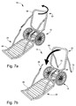
- FIGS. 7 a - 7 c are perspective views of a cart according to one embodiment of the instant invention showing one method of folding the cart for transportation and/or storage.
- FIGS. 8 a - 8 d are perspective views of a kit according to one embodiment of the instant invention showing one method of folding the kit for transportation and/or storage.
- kit 10 for converting a climbing tree stand 12 into a cart 14 , also known as a hauler, deer cart or deer hauler.
- the kit 10 may be ideally utilized for converting a climbing tree stand into a cart.
- kit 10 may be utilized for other tree stand types or other devices needed to be converted into a cart.
- kit 10 may also be utilized for converting such devices to any type of various carts, vehicles, wagons, scooters, etc.
- Kit 10 may convert the climbing tree stand 12 into any form of a cart, a hauler, a deer cart, a deer hauler, etc.
- kit 10 may be designed with hunters in mind, however, kit 10 may also be utilized by other users with for other various activities requiring a tree stand and/or a cart.
- Kit 10 may include any parts for converting a climbing tree stand into a cart.
- kit 10 may include a bracket 16 .
- Bracket 16 may be included in kit 10 for converting a climbing tree stand 12 into a cart 14 . See FIGS. 1-5 and 8 . Bracket 16 may be for connecting the top part 22 of climbing tree stand 12 to bottom part 24 of climbing tree stand 12 . Bracket 16 may include any parts or combination of parts for connecting top part 22 to bottom part 24 of climbing tree stand 12 . The connection of top part 22 to bottom part 24 of climbing tree stand 12 may convert the stand into the cart 14 . Bracket 16 may have a first side 18 and a second side 20 . The first side 18 may be shaped to attach to top part 22 of climbing tree stand 12 , the second side 20 may be shaped to attach to bottom part 24 of climbing tree stand 12 , or vice versa.
- first side 18 and/or second side 20 of bracket 16 may be shaped to fit any climbing tree stand or other tree stand with a top and bottom part ( 22 and 24 ).
- the bracket 16 may convert the climbing tree stand 12 into a cart 14 by attaching the top part 22 (also known as the seat climber 64 ) of the climbing tree stand 12 to first side 18 and attaching the bottom part 24 (also know as the base platform 66 ) of the climbing tree stand 12 to the second side 20 .
- the bracket 16 may be sized or shaped according to the desired climbing tree stand to be converted. In one embodiment, bracket 16 may have a hexagonal shape.
- the bracket 16 may be made from a single piece of material cast or stamped out or it may be made from multiple materials attached together, like, by welding.
- the bracket 16 may be made from any type of material strong enough to support cart 14 , including, but not limited to, steel aluminum, alloys, other like materials, etc.
- bracket 16 may be made from aluminum tubing, aluminum channels, and/or aluminum rods.
- bracket 16 may be constructed from Aluminum (6063 T52) u-channel tubing 1.25′′ ⁇ 1.25′′ ⁇ 0.125′′ welded together. Such aluminum u-channel may be available as part number 13-63-230 from AAC—All Aluminum Company of Asheville, N.C.
- the first side 18 may be shaped to attach to a tree gripping means 28 of the top part 22 and/or the second side 20 may be shaped to attach to a tree gripping means 30 of the bottom part 24 of climbing tree stand 12 . See FIGS. 2-4 .
- the top and bottom tree gripping means ( 28 and 30 ) of the climbing tree stand 12 can be any tree gripping means commonly used with tree stands or any tree gripping means developed in the future for tree stands.
- the first side 18 and second side 20 of bracket 16 may be shaped or designed to fit any style, shape or size tree stand or climbing tree stand, including any various style, shape or size of tree gripping means utilized on such various climbing tree stands.
- first side 18 may be shaped to attach to an inner portion 32 of the top tree gripping means 28
- second side 20 may be shaped to attach to an inner portion 34 of the bottom tree gripping means 30
- the first side 18 and/or second side 20 may have a convex shape 36 .
- This convex shape of first side 18 and/or second side 20 may be designed to conform to the respective inner portions ( 32 and 34 ) of top and/or bottom tree gripping means ( 28 and 30 ).
- Inner portions of standard climbing tree stands are typically concave shaped.
- the first side 18 may have a first u-shaped channel 38 and/or the second side 20 may have a second u-shaped channel 40 .
- the first u-shaped channel 38 and/or the second u-shaped channel 40 may be for receiving the respective top and/or bottom tree gripping means ( 28 and 30 ).
- the first u-shaped channel 38 may be for receiving the teeth 42 of top tree gripping means 28
- the second u-shaped channel 40 may be for receiving the teeth 44 of bottom tree gripping means 30 .
- the first side 18 and second side 20 of bracket 16 may attach to top part 22 and bottom part 24 of climbing tree stand 12 . See FIGS. 1-3 .
- the first and second sides ( 18 and 20 ) may attach to the respective top and bottom part ( 22 and 24 ) of climbing tree stand 12 , or vice versa, by any means, including, but not limited to, any brackets, fasteners, nails, screws, pins, locks, straps, ties, the like, and any combinations thereof.
- the first side 18 and/or the second side 20 of bracket 16 may be removably attachable to the respective top and/or bottom parts ( 22 and 24 ) of climbing tree stand 12 , or vice versa.
- the first side 18 may be removably attachable to the top part 22 of climbing tree stand 12 via at least one first strap 46
- the second side 20 may be removably attachable to the bottom part 24 of the climbing tree stand 12 via at least one second strap 48
- the first and second straps 46 and 48 may be similar or they may be different based on the similarities between the connections and the needs of attachment to the top and bottom parts ( 22 and 24 ) of the climbing tree stand 12
- the first and second straps 46 and 48 may be any straps for removably connecting the first and second sides 18 and 20 with the respective top and bottom parts 22 and 24 .
- the first strap may include a first cinch strap 50 (could also be a hook and loop type fastener or other like fastener) for securing the first strap 46 around the first side 18 and the top part 22 of the climbing tree stand 12 .
- the second strap 48 may include a second cinch strap 52 (could also be a hook and loop type fastener or other like fastener) for securing the second strap 48 around the second side 20 and the bottom part 24 of the climbing tree stand 12 .
- the combination of the convex shape 36 of first side 18 with the first u-shaped channel 38 adapted to receive the teeth 42 of top tree gripping means 28 may allow a single first strap 46 anywhere (preferably in the middle) to secure the first side 18 onto the top part 22 or seat climber 64 of climbing tree stand 12 .
- the combination of the convex shape 36 of second side 20 with the second u-shaped channel 40 adapted to receive the teeth 44 of bottom tree gripping means 30 may allow a single second strap 48 anywhere (preferably in the middle) to secure the second side 20 onto the bottom part 24 or base platform 66 of climbing tree stand 12 .
- This attachment of first side 18 to top part 22 and/or second side 20 to bottom part 24 with a single removable strap allows for easy conversion back and forth from climbing tree stand 12 to cart 14 .
- An axle 26 may be included on bracket 16 in kit 10 for converting a climbing tree stand 12 into a cart 14 . See FIG. 4 Axle 26 may be for providing the axle for wheels 62 . Axle 26 may be any sized or shaped axle. Axle 26 may be positioned anywhere on bracket 16 . In one embodiment, axle 26 may be positioned in the middle of bracket 16 between first side 18 and second side 20 . In one embodiment, axle 26 may be a cylindrical rod extending a small distance beyond both sides of bracket 16 . Axle 26 may be a single unitary axle that runs this distance, or it may be divided into two parts with one part of the axle supporting one wheel and the other part of the axle supporting the other wheel.
- Axle 26 may be made of any material strong enough to support the weight of cart 14 on wheels 62 and any desired weight in cart 14 , like steel, aluminum, alloys, other like materials, etc.
- axle 26 may be made from a metal, like steel or stainless steel.
- At least one wheel 62 may be provided on axle 26 .
- a wheel 62 may be provided on each end of axle 26 .
- the at least one wheel 62 may be any type or sized wheel adapted to rotate on axle 26 .
- the wheels 62 may be a flat-free solid polyurethane tire including, but not limited to, part #16-1.75-5 ⁇ 8 from Marathon Industries of Kent, Wash.
- the wheels 62 may be held in position onto axle 26 by any means.
- each wheel 62 may be held in position on axle 26 by use of a cotter pin (as shown in FIG. 4 ), nut, or other locking mechanism.
- a washer may optionally be included between the respective wheel 62 and the locking mechanism.
- Bracket 16 may be a single unitary structure adapted for connecting together top part 22 and bottom part 24 of climbing tree stand 12 , or bracket 16 may be made from multiple parts for connecting together top part 22 and bottom part 24 .
- bracket 16 may include a first bracket 54 and a second bracket 56 .
- First bracket 54 may include first side 18 on one end and second bracket 56 may include second side 20 on one end.
- the axle 26 may be positioned anywhere on first bracket 54 and/or second bracket 56 .
- the axle 26 may be positioned between the first bracket 54 and the second bracket 56 .
- the axle 26 may be utilized to connect together first bracket 54 and second bracket 56 .
- the first bracket 54 may have a middle tube 58 adapted to receive the axle 26 on the other end from the first side 18 and/or the second bracket 56 may have two outer tubes 60 adapted to receive axle 26 on the other end from second side 20 .
- the middle tube 58 of the first bracket 54 may be sized to fit between the two outer tubes 60 of second bracket 56 .
- the axle 26 may be utilized to connect together the first bracket 54 and the second bracket 56 by inserting the axle 26 through the two outer tubes 60 and the middle tube 58 .
- This configuration of the first bracket 54 and second bracket 56 may allow the bracket to rotate about each other via the pivot point of axle 26 .
- any form of lock may be used, including but not limited to, pins, screws, nails, locks, rivets, grooves, brackets, cables, ties, hook and loop fasteners, cinch-straps, ratchet straps or the like, other like devices, combinations thereof, etc.
- the cables 68 from bottom part 24 may be locked into the connection points 70 on top part 22 (or vice versa) for locking the angle of the first bracket 54 relative to the second bracket 56 .
- This locked in angle of first bracket 54 relative to second bracket 56 may create the angle of cart 14 shown in the Figures, which may aid in keeping objects or game inside of cart 14 .
- First bracket 54 and second bracket 56 may be designed with similar shapes or may be different.
- first bracket 54 may be one half of a hexagon
- second bracket 56 may be the other half of the hexagon.
- the two brackets 54 and 56 may each be made from a single piece of material cast or stamped out or it may be made from multiple materials attached together, like, by welding.
- the first bracket 54 and second bracket 56 may be made from any type of material strong enough to support cart 14 .
- first and second brackets ( 54 and 56 ) may be made from aluminum channels.
- the two brackets may be constructed from aluminum (6063 T52) U-channels 1.25′′ ⁇ 1.25′′ ⁇ 0.125′′ welded together. Such aluminum u-channels may be available as part number 13-63-230 from AAC—All Aluminum Company of Asheville, N.C.
- the middle tube 58 and two outer tubes 60 may also be made of any material strong enough to support axle 26 .
- middle tube 58 and/or two outer tubes 60 may be constructed from aluminum (6063 T52) round tube 3 ⁇ 4′′ ⁇ 0.065′′.
- Example round aluminum tubing may be available as part number 17-63-100 from AAC—All Aluminum Company of Asheville, N.C.
- the two brackets 54 and 56 may be made from a single piece of material or it may be made from multiple materials attached together, like, by welding.
- the cart 14 may require an angle between top part 22 and bottom part 24 for keeping object like game or other animals in the cart more easily during transportation.
- the angle between top part 22 and bottom part 24 may be created by an angle within bracket 16 between the first side 18 and the second side 20 . In one embodiment, this angle may be a fixed angle between first bracket 54 and second bracket 56 .
- bracket 16 may be able to pivot about itself for creating the angle for cart 14 . Such a pivoting embodiment of bracket 16 may be created by the first bracket 54 having a middle tube 58 and second bracket 56 having two outer tubes 60 , where the axle 26 connects together first bracket 54 and second bracket 56 and the axle 26 is the pivot point within bracket 16 .
- the cables 68 or hook and loop fasteners, cinch-straps, ratchet straps, or the like
- connections 70 of the top part 22 and bottom part 24 may be utilized for locking the cart 14 into the desired angle.
- the climbing tree stand 12 that kit 10 may be utilized on to convert into cart 14 may be any tree stand or climbing tree stand.
- the climbing tree stand 12 may typically include a top part 22 being a seat climber 64 and a bottom part 24 being a base platform 66 .
- the climbing tree stand 12 may include any optional features or accessories on or attached to seat climber 64 and/or base platform 66 .
- climbing tree stand 12 may include a seat, seat back, arm rests, cushions, etc. on seat climber 64 .
- the kit 10 may convert any size, shape or design of climbing tree stand 12 into a cart 14 .
- the cart 14 would generally include the seat climber 64 attached to one side of the kit 10 and the base platform 66 attached to the other side of the kit 10 .
- the cart 14 may then be easily wheeled around by pushing or pulling either seat climber 64 or base platform 66 .
- a cart 14 may be formed. As shown in FIG. 6 a , the cart 14 may rest on bottom part 24 . Although, not shown, cart 14 may also rest on top part 22 in a reverse fashion. As shown in FIG. 6 b , while the cart 14 is at rest, game, animals, or other desired objects, may be loaded onto cart 14 . As shown in FIG. 6 c , once the object is loaded, cart 14 may be leveraged off of bottom part 24 by pulling up on bottom part 24 and/or by pulling down on top part 22 . Once both top part 22 and bottom part 24 are leveraged off of the ground so that only wheels 62 are contacting the ground, the cart 14 may be pulled or pushed in either direction.
- FIGS. 7 a - 7 c a method of folding cart 14 is shown for making cart 14 smaller or more compact for transportation and/or storage.
- the top part 22 can be removed from bracket 16 and installed in reverse fashion. This will allow top part 22 to fold onto and next into bottom part 24 , as shown in FIG. 7 c .
- This method of folding cart 14 may reduce the size of cart 14 which, as one skilled in the art should readily understand, may allow cart 14 to be more easily transported and/or stored.
- kit 10 a method of folding kit 10 is shown for making kit 10 smaller or more compact for transportation and/or storage.
- the first step is to fold first bracket 54 onto second bracket 56 , or vice versa.
- the kit 10 may be more compact and easier for transportation and storage. This method is used when kit 10 is to be transported and/or stored separate from tree stand 12 .
- one wheel 62 may be removed off of the axle 26 and added to the same side of the axle 26 as the other wheel 62 .
- This method may also be utilized for transporting kit 10 inside of tree stand 12 , when tree stand 12 is folding into a backpack configuration, as known by one skilled in the art. With both wheels 62 positioned on one side of axle 26 , the other side of bracket 16 may be relatively compact and thus easily slid into the backpack configuration of the climbing tree stand.
- the instant invention also includes a method of converting climbing tree stand 12 into cart 14 .
- This method may include any steps or procedures required to convert climbing tree stand 12 into cart 14 .
- the method may include the steps of: providing climbing tree stand 12 including: top part 22 that is a seat climber 64 ; and a bottom part 24 that is a base platform 66 ; providing kit 10 as shown and described herein, attaching first side 18 of bracket 16 to top part 22 of the climbing tree stand 12 ; and attaching the second side 20 of the bracket 16 to the bottom part 24 of the climbing tree stand 12 .
Abstract
A kit for converting a climbing tree stand into a cart includes a bracket having a first side and a second side. The first side is shaped to attach to a top part of a climbing tree stand. The second side is shaped to attach to a bottom part of the climbing tree stand. At least one wheel with an axle is positioned on the bracket. The bracket converts the climbing tree stand into a cart by attaching the top part of the climbing tree stand to the first side and attaching the bottom part of the climbing tree stand to the second side.
Description
The present invention relates generally to parts for a tree stand, like a climbing tree stand. More particularly, the present invention relates to a kit for converting a climbing tree stand into a cart.
Tree stands or deer stands are open or enclosed platforms used to provide an elevated position in a tree. Tree stands are commonly used in the hunting world, like deer hunting. The platforms are secured to trees in order to elevate the hunter and give the hunter a better vantage point. The majority of the millions of deer hunters in the U.S. use a tree stand. Hunters use many different types of tree stands, like ladder-style tree stands, climbing tree stands, hanging stands, box stands, etc. The instant invention is designed to be utilized with a climbing tree stand.
A climbing tree stand is used by a person to not only provide an elevated position in a tree, but it also aids the user in climbing the tree. Climbing tree stands are typically made of two parts, a bottom part and a top part. The bottom part is the standing platform and the top part is the seat. A strap may be included that connects the top part to the bottom part, so if the bottom falls while in the tree or climbing, the platform doesn't fall all the way to the ground stranding the hunter. Climbing tree stands come in many different shapes and sizes and with many different accessories, like seats, seat backs, arm rests, cushions, footrests, etc. Climbing tree stands have a couple of different styles to connect to the tree. The tree gripping part, or the part that grips the lower portion of the tree, is typically made from a concave shaped piece of metal with teeth or grooves utilized to grip the tree. An adjustable cable portion is wrapped around the tree above the tree gripping part to provide the cantilever forces required to position the top and/or bottom part on the tree.
Before climbing the tree both parts need to be adjusted to the tree so they are level for the hunter to stand and sit on. To climb the tree the back of each part is angled to the tree one at a time and pulled up. Then the part that the hunter is moving is set back level and the next part is moved up. This is done until the person is at the desired height. For safety some hunters strap the tree stand to the tree. To go down the hunter does the same as climbing up except in reverse. Obviously, only trees that have no limbs up to the height desired for hunting will work.
One issue with tree stands and hunting is that tree stands are heavy and bulky, and thus, very difficult to transport. Typical climbing tree stands weigh between 18-30 pounds. The transportation of a tree stand becomes even more difficult for long distances. For example, some public hunting lands restrict the use of motorized vehicles, thereby requiring hunters to manually carry their equipment to the desired hunting location. As most should understand, the more remote the location is or the farther the location is away from human development, the more likely the hunter is to see any game animals, like deer. Thus, most hunters desire their hunting location to be deep into the woods or hunting land. As such, some hunters may walk or bike multiple miles to their desired hunting location. Thus, there is clearly a need to provide a climbing tree stand that is easier to transport, especially for long distances.
Another issue most hunters face is the transportation of the killed game or animal back from the hunting location. As most any person should understand, it is very difficult to transport dead weight, especially for long distances. For example, the average deer weighs around 200 pounds which is extremely difficult for a single person to carry, especially for long distances back from the hunting location. Thus, there is clearly a need to provide a means for transporting the killed game back from the hunting location.
One solution to transporting climbing tree stands is that the top part and bottom part can be sized to nest together and transport like a backpack. One solution to transporting a killed animal back from the hunting location is to use a cart or hauler, or a deer cart. However, no one wants to carry a 30 lb. stand and a 30 lb cart into the woods on each trip. Thus, there is clearly a need to create a light weight, compact, low cost “kit” to convert the typical climbing tree stand into a deer cart/hauler.
The instant invention is designed to address the problems described above and provide a kit for converting a climbing tree stand into a deer cart.
The instant invention is directed toward a kit for converting a climbing tree stand into a cart. The kit includes a bracket having a first side and a second side. The first side is shaped to attach to a top part of a climbing tree stand. The second side is shaped to attach to a bottom part of the climbing tree stand. At least one wheel with an axle is positioned on the bracket. The bracket converts the climbing tree stand into a cart by attaching the top part of the climbing tree stand to the first side and attaching the bottom part of the climbing tree stand to the second side.
For the purpose of illustrating the invention, there is shown in the drawings a form that is presently preferred; it being understood, however, that this invention is not limited to the precise arrangements and instrumentalities shown.
Referring to the drawings, wherein like numerals indicate like elements, there is shown in FIG. 1 an embodiment of a kit 10 for converting a climbing tree stand 12 into a cart 14, also known as a hauler, deer cart or deer hauler. As described and shown herein, the kit 10 may be ideally utilized for converting a climbing tree stand into a cart. However, the invention is not so limited, and kit 10 may be utilized for other tree stand types or other devices needed to be converted into a cart. In addition, kit 10 may also be utilized for converting such devices to any type of various carts, vehicles, wagons, scooters, etc. Kit 10 may convert the climbing tree stand 12 into any form of a cart, a hauler, a deer cart, a deer hauler, etc. As discussed herein, kit 10 may be designed with hunters in mind, however, kit 10 may also be utilized by other users with for other various activities requiring a tree stand and/or a cart. Kit 10 may include any parts for converting a climbing tree stand into a cart. In one embodiment, kit 10 may include a bracket 16.
In one embodiment of bracket 16, the first side 18 may be shaped to attach to a tree gripping means 28 of the top part 22 and/or the second side 20 may be shaped to attach to a tree gripping means 30 of the bottom part 24 of climbing tree stand 12. See FIGS. 2-4 . The top and bottom tree gripping means (28 and 30) of the climbing tree stand 12 can be any tree gripping means commonly used with tree stands or any tree gripping means developed in the future for tree stands. Thus, as should be readily understood by one skilled in the art, the first side 18 and second side 20 of bracket 16 may be shaped or designed to fit any style, shape or size tree stand or climbing tree stand, including any various style, shape or size of tree gripping means utilized on such various climbing tree stands. In one embodiment, the first side 18 may be shaped to attach to an inner portion 32 of the top tree gripping means 28, and/or the second side 20 may be shaped to attach to an inner portion 34 of the bottom tree gripping means 30. The first side 18 and/or second side 20 may have a convex shape 36. This convex shape of first side 18 and/or second side 20 may be designed to conform to the respective inner portions (32 and 34) of top and/or bottom tree gripping means (28 and 30). Inner portions of standard climbing tree stands are typically concave shaped. In one embodiment, the first side 18 may have a first u-shaped channel 38 and/or the second side 20 may have a second u-shaped channel 40. The first u-shaped channel 38 and/or the second u-shaped channel 40 may be for receiving the respective top and/or bottom tree gripping means (28 and 30). In one embodiment, the first u-shaped channel 38 may be for receiving the teeth 42 of top tree gripping means 28, and/or the second u-shaped channel 40 may be for receiving the teeth 44 of bottom tree gripping means 30.
The first side 18 and second side 20 of bracket 16 may attach to top part 22 and bottom part 24 of climbing tree stand 12. See FIGS. 1-3 . The first and second sides (18 and 20) may attach to the respective top and bottom part (22 and 24) of climbing tree stand 12, or vice versa, by any means, including, but not limited to, any brackets, fasteners, nails, screws, pins, locks, straps, ties, the like, and any combinations thereof. As should be readily understood by those skilled in the art, the first side 18 and/or the second side 20 of bracket 16 may be removably attachable to the respective top and/or bottom parts (22 and 24) of climbing tree stand 12, or vice versa. In one embodiment, the first side 18 may be removably attachable to the top part 22 of climbing tree stand 12 via at least one first strap 46, and/or the second side 20 may be removably attachable to the bottom part 24 of the climbing tree stand 12 via at least one second strap 48. The first and second straps 46 and 48 may be similar or they may be different based on the similarities between the connections and the needs of attachment to the top and bottom parts (22 and 24) of the climbing tree stand 12. The first and second straps 46 and 48 may be any straps for removably connecting the first and second sides 18 and 20 with the respective top and bottom parts 22 and 24. In one embodiment, the first strap may include a first cinch strap 50 (could also be a hook and loop type fastener or other like fastener) for securing the first strap 46 around the first side 18 and the top part 22 of the climbing tree stand 12. In another embodiment, the second strap 48 may include a second cinch strap 52 (could also be a hook and loop type fastener or other like fastener) for securing the second strap 48 around the second side 20 and the bottom part 24 of the climbing tree stand 12. The combination of the convex shape 36 of first side 18 with the first u-shaped channel 38 adapted to receive the teeth 42 of top tree gripping means 28, may allow a single first strap 46 anywhere (preferably in the middle) to secure the first side 18 onto the top part 22 or seat climber 64 of climbing tree stand 12. Likewise, the combination of the convex shape 36 of second side 20 with the second u-shaped channel 40 adapted to receive the teeth 44 of bottom tree gripping means 30, may allow a single second strap 48 anywhere (preferably in the middle) to secure the second side 20 onto the bottom part 24 or base platform 66 of climbing tree stand 12. This attachment of first side 18 to top part 22 and/or second side 20 to bottom part 24 with a single removable strap allows for easy conversion back and forth from climbing tree stand 12 to cart 14.
An axle 26 may be included on bracket 16 in kit 10 for converting a climbing tree stand 12 into a cart 14. See FIG. 4 Axle 26 may be for providing the axle for wheels 62. Axle 26 may be any sized or shaped axle. Axle 26 may be positioned anywhere on bracket 16. In one embodiment, axle 26 may be positioned in the middle of bracket 16 between first side 18 and second side 20. In one embodiment, axle 26 may be a cylindrical rod extending a small distance beyond both sides of bracket 16. Axle 26 may be a single unitary axle that runs this distance, or it may be divided into two parts with one part of the axle supporting one wheel and the other part of the axle supporting the other wheel. Axle 26 may be made of any material strong enough to support the weight of cart 14 on wheels 62 and any desired weight in cart 14, like steel, aluminum, alloys, other like materials, etc. In one embodiment, axle 26 may be made from a metal, like steel or stainless steel. At least one wheel 62 may be provided on axle 26. In one embodiment, a wheel 62 may be provided on each end of axle 26. The at least one wheel 62 may be any type or sized wheel adapted to rotate on axle 26. For example, the wheels 62 may be a flat-free solid polyurethane tire including, but not limited to, part #16-1.75-⅝ from Marathon Industries of Kent, Wash. The wheels 62 may be held in position onto axle 26 by any means. In one embodiment, each wheel 62 may be held in position on axle 26 by use of a cotter pin (as shown in FIG. 4 ), nut, or other locking mechanism. A washer may optionally be included between the respective wheel 62 and the locking mechanism.
The cart 14 may require an angle between top part 22 and bottom part 24 for keeping object like game or other animals in the cart more easily during transportation. The angle between top part 22 and bottom part 24 may be created by an angle within bracket 16 between the first side 18 and the second side 20. In one embodiment, this angle may be a fixed angle between first bracket 54 and second bracket 56. In another embodiment, bracket 16 may be able to pivot about itself for creating the angle for cart 14. Such a pivoting embodiment of bracket 16 may be created by the first bracket 54 having a middle tube 58 and second bracket 56 having two outer tubes 60, where the axle 26 connects together first bracket 54 and second bracket 56 and the axle 26 is the pivot point within bracket 16. In this embodiment, because the first and second brackets pivot freely about each other, the cables 68 (or hook and loop fasteners, cinch-straps, ratchet straps, or the like) and connections 70 of the top part 22 and bottom part 24 may be utilized for locking the cart 14 into the desired angle.
In operation, the climbing tree stand 12 that kit 10 may be utilized on to convert into cart 14 may be any tree stand or climbing tree stand. The climbing tree stand 12 may typically include a top part 22 being a seat climber 64 and a bottom part 24 being a base platform 66. The climbing tree stand 12 may include any optional features or accessories on or attached to seat climber 64 and/or base platform 66. For example, climbing tree stand 12 may include a seat, seat back, arm rests, cushions, etc. on seat climber 64. The kit 10 may convert any size, shape or design of climbing tree stand 12 into a cart 14. The cart 14 would generally include the seat climber 64 attached to one side of the kit 10 and the base platform 66 attached to the other side of the kit 10. The cart 14 may then be easily wheeled around by pushing or pulling either seat climber 64 or base platform 66.
Referring to FIGS. 6 a-6 c, once the kit 10 is connected to both the top part 22 and bottom part 24, a cart 14 may be formed. As shown in FIG. 6 a, the cart 14 may rest on bottom part 24. Although, not shown, cart 14 may also rest on top part 22 in a reverse fashion. As shown in FIG. 6 b, while the cart 14 is at rest, game, animals, or other desired objects, may be loaded onto cart 14. As shown in FIG. 6 c, once the object is loaded, cart 14 may be leveraged off of bottom part 24 by pulling up on bottom part 24 and/or by pulling down on top part 22. Once both top part 22 and bottom part 24 are leveraged off of the ground so that only wheels 62 are contacting the ground, the cart 14 may be pulled or pushed in either direction.
Referring to FIGS. 7 a-7 c, a method of folding cart 14 is shown for making cart 14 smaller or more compact for transportation and/or storage. As shown in FIGS. 7 a-7 b, the top part 22 can be removed from bracket 16 and installed in reverse fashion. This will allow top part 22 to fold onto and next into bottom part 24, as shown in FIG. 7 c. This method of folding cart 14, may reduce the size of cart 14 which, as one skilled in the art should readily understand, may allow cart 14 to be more easily transported and/or stored.
Referring to FIGS. 8 a-8 d, a method of folding kit 10 is shown for making kit 10 smaller or more compact for transportation and/or storage. As shown in FIGS. 8 a-8 b, the first step is to fold first bracket 54 onto second bracket 56, or vice versa. Once folded like in FIG. 8 b, the kit 10 may be more compact and easier for transportation and storage. This method is used when kit 10 is to be transported and/or stored separate from tree stand 12. As show in FIGS. 8 c-8 d, if the user prefers, one wheel 62 may be removed off of the axle 26 and added to the same side of the axle 26 as the other wheel 62. This method may also be utilized for transporting kit 10 inside of tree stand 12, when tree stand 12 is folding into a backpack configuration, as known by one skilled in the art. With both wheels 62 positioned on one side of axle 26, the other side of bracket 16 may be relatively compact and thus easily slid into the backpack configuration of the climbing tree stand.
The instant invention also includes a method of converting climbing tree stand 12 into cart 14. This method may include any steps or procedures required to convert climbing tree stand 12 into cart 14. In one embodiment, the method may include the steps of: providing climbing tree stand 12 including: top part 22 that is a seat climber 64; and a bottom part 24 that is a base platform 66; providing kit 10 as shown and described herein, attaching first side 18 of bracket 16 to top part 22 of the climbing tree stand 12; and attaching the second side 20 of the bracket 16 to the bottom part 24 of the climbing tree stand 12.
The present invention may be embodied in other forms without departing from the spirit and the essential attributes thereof, and, accordingly, reference should be made to the appended claims, rather than to the foregoing specification, as indicating the scope of the invention.
Claims (16)
1. A kit for converting a climbing tree stand into a cart, comprising:
a top part of a climbing tree stand having a tree gripping means with an inner portion;
a bottom part of a climbing tree stand having a tree gripping means with an inner portion;
a bracket having a first side and a second side;
said first side being shaped to attach to the inner portion of the tree gripping means of the top part of the climbing tree stand;
said second side being shaped to attach to the inner portion of the tree gripping means of the bottom part of said climbing tree stand; and
at least one wheel with an axle being positioned on said bracket;
whereby, said bracket converts said climbing tree stand into a cart by attaching said inner portion of the tree gripping means of the top part of said climbing tree stand to said first side and attaching said inner portion of the tree gripping means of the bottom part of said climbing tree stand to said second side.
2. The kit for converting a climbing tree stand into a cart of claim 1 wherein:
said first side having a convex shape, and
said second side having a convex shape.
3. The kit for converting a climbing tree stand into a cart of claim 1 wherein:
said first side having a first u-shaped channel, and
said second side having a second-u-shaped channel.
4. The kit for converting a climbing tree stand into a cart of claim 3 wherein:
said first u-shaped channel being sized to receive teeth of said tree gripping means of said top part, and
said second u-shaped channel being sized to receive teeth of the tree gripping means of said bottom part.
5. The kit for converting a climbing tree stand into a cart of claim 1 wherein:
said first side being removably attachable to the top part of said climbing tree stand, and
said second side being removably attachable to the bottom part of said climbing tree stand.
6. The kit for converting a climbing tree stand into a cart of claim 5 wherein:
said first side being removably attachable to the top part of said climbing tree stand via a first strap, and
said second side being removably attachable to the bottom part of said climbing tree stand via a second strap.
7. The kit for converting a climbing tree stand into a cart of claim 6 wherein:
said first strap including a first cinch strap for securing the strap around said first side and the top part of said climbing tree stand, and
said second strap including a second cinch strap for securing the strap around said second side and the bottom part of said climbing tree stand.
8. The kit for converting a climbing tree stand into a cart of claim 1 wherein said bracket comprising:
a first bracket with said first side on one end; and
a second bracket with said second side on one end.
9. The kit for converting a climbing tree stand into a cart of claim 8 wherein said axle being positioned between said first bracket and said second bracket.
10. The kit for converting a climbing tree stand into a cart of claim 9 wherein said axle connecting together said first bracket and said second bracket.
11. The kit for converting a climbing tree stand into a cart of claim 10 wherein said first bracket having a middle tube adapted to receive said axle on the other end from said first side, and said second bracket having two outer tubes adapted to receive said axle on the other end from said second side, where said middle tube of said first bracket being sized to fit between said two outer tubes of said second bracket.
12. The kit for converting a climbing tree stand into a cart of claim 11 whereby said axle connecting together said first bracket and said second bracket by positioning said middle tube between said two outer tubes and inserting said axle through said two outer tubes and said middle tube.
13. The kit for converting a climbing tree stand into a cart of claim 1 wherein said at least one wheel includes two wheels, where said axle having a wheel on both ends.
14. A kit for converting a climbing tree stand into a cart, comprising:
a top part of a climbing tree stand having a tree gripping means with an inner portion;
a bottom part of a climbing tree stand having a tree gripping means with an inner portion;
a bracket having a first side and a second side;
said first side being shaped to attach to the tree gripping means with teeth of the top part of the climbing tree stand, wherein said first side having a first u-shaped channel sized to receive the teeth of the tree gripping means of said top part;
said second side being shaped to attach the tree gripping means with teeth of the bottom part of said climbing tree stand, wherein said second side having a second u-shaped channel sized to receive the teeth of the tree gripping means of said bottom part; and
at least one wheel with an axle being positioned on said bracket;
whereby, said bracket converts said climbing tree stand into a cart by attaching said tree gripping means with teeth of the top part of said climbing tree stand to said first side and attaching said tree gripping means with teeth of the bottom part of said climbing tree stand to said second side.
15. A kit for converting a climbing tree stand into a cart, comprising:
a top part of a climbing tree stand and a bottom part of a climbing tree stand;
a bracket having a first side and a second side;
said first side being shaped to attach to the top part of the climbing tree stand, wherein said first side being removably attachable to the top part of said climbing tree stand via a first strap;
said second side being shaped to attach the bottom part of said climbing tree stand, wherein said second side being removable attachable to the bottom part of said climbing tree stand via a second strap; and
at least one wheel with an axle being positioned on said bracket;
whereby, said bracket converts said climbing tree stand into a cart by attaching said top part of said climbing tree stand to said first side and attaching said bottom part of said climbing tree stand to said second side.
16. A kit for converting a climbing tree stand into a cart comprising: a top part of a climbing tree stand and a bottom part of a climbing tree stand;
a bracket having a first side and a second side;
said first side being shaped to attach to a top part of the climbing tree stand;
said second side being shaped to attach a bottom part of said climbing tree stand; and
at least one wheel with an axle being positioned on said bracket;
wherein, said bracket comprising:
a first bracket with said first side on one end; and
a second bracket with said second side on one end;
said axle being positioned between said first bracket and said second bracket;
wherein, said axle connecting together said first bracket and said second bracket; and
wherein, said first bracket having a middle tube adapted to receive said axle on the other end from said first side, and said second bracket having two outer tubes adapted to receive said axle on the other end from said second side, where said middle tube of said first bracket being sized to fit between said two outer tubes of said second bracket;
whereby, said bracket converts said climbing tree stand into a cart by attaching said top part of said climbing tree stand to said first side and attaching said bottom part of said climbing tree stand to said second side.
Priority Applications (1)
| Application Number | Priority Date | Filing Date | Title |
|---|---|---|---|
| US13/773,805 US9265244B2 (en) | 2013-02-22 | 2013-02-22 | Kit for converting a climbing tree stand into a cart |
Applications Claiming Priority (1)
| Application Number | Priority Date | Filing Date | Title |
|---|---|---|---|
| US13/773,805 US9265244B2 (en) | 2013-02-22 | 2013-02-22 | Kit for converting a climbing tree stand into a cart |
Publications (2)
| Publication Number | Publication Date |
|---|---|
| US20140238776A1 US20140238776A1 (en) | 2014-08-28 |
| US9265244B2 true US9265244B2 (en) | 2016-02-23 |
Family
ID=51387010
Family Applications (1)
| Application Number | Title | Priority Date | Filing Date |
|---|---|---|---|
| US13/773,805 Active 2033-12-01 US9265244B2 (en) | 2013-02-22 | 2013-02-22 | Kit for converting a climbing tree stand into a cart |
Country Status (1)
| Country | Link |
|---|---|
| US (1) | US9265244B2 (en) |
Cited By (4)
| Publication number | Priority date | Publication date | Assignee | Title |
|---|---|---|---|---|
| US9993718B2 (en) * | 2013-10-21 | 2018-06-12 | Equalia LLC | Pitch-propelled vehicle |
| USD832461S1 (en) | 2017-06-20 | 2018-10-30 | Clark Ashley, Jr. | Set of wheels for a ladder tree stand |
| US10307659B2 (en) | 2013-10-21 | 2019-06-04 | Equalia LLC | Pitch-propelled vehicle |
| US10369453B2 (en) | 2013-10-21 | 2019-08-06 | Equalia LLC | Pitch-propelled vehicle |
Families Citing this family (4)
| Publication number | Priority date | Publication date | Assignee | Title |
|---|---|---|---|---|
| US9137982B2 (en) * | 2013-04-22 | 2015-09-22 | Kevin L. Yoder | Convertible treestand |
| US9832989B2 (en) * | 2014-05-15 | 2017-12-05 | Minis R. Hillis | Octagon portable tree platform |
| US10034472B2 (en) * | 2014-09-19 | 2018-07-31 | Stephen J Prescott, Sr. | Tree seat and hauler device and method |
| US20170027159A1 (en) * | 2015-07-30 | 2017-02-02 | Michael R. Johnson | Dual Anchor Climbing Tree Stand |
Citations (48)
| Publication number | Priority date | Publication date | Assignee | Title |
|---|---|---|---|---|
| US2375338A (en) * | 1943-10-09 | 1945-05-08 | Edith F Alexander | Luggage carriage |
| US2426244A (en) * | 1945-01-01 | 1947-08-26 | Philip N Sitton | Dolly |
| US2979338A (en) * | 1959-05-08 | 1961-04-11 | Arthur J Dwyer | Game cart |
| US3860254A (en) * | 1970-10-26 | 1975-01-14 | Harold William Wegener | Foldable packer |
| US4321982A (en) | 1980-06-23 | 1982-03-30 | Strickland Robert E | Tree climbing-hunting and game cart device |
| US4440409A (en) * | 1981-07-13 | 1984-04-03 | Margison Alan B | Boat transporter |
| US4582165A (en) * | 1985-08-08 | 1986-04-15 | Latini Lawrence R | Pack frame and tree stand |
| US4822065A (en) * | 1987-08-03 | 1989-04-18 | Enders Irvin D | Collapsible cargo carrier |
| US5048850A (en) * | 1990-09-17 | 1991-09-17 | Mcdonald Don C | Wheeled article carrier |
| US5181731A (en) * | 1991-08-30 | 1993-01-26 | Willard Gustavsen | Pivotable cart |
| US5265780A (en) * | 1992-06-05 | 1993-11-30 | Matthews Timothy I | Combined backpack frame and climbing stand |
| US5295556A (en) | 1992-08-03 | 1994-03-22 | Mullin Daniel J | Multipurpose hunting cart |
| US5433291A (en) | 1994-12-07 | 1995-07-18 | Shoestock, Sr.; Richard F. | Combination tree stand and wheeled game carrier |
| US5492196A (en) | 1994-12-07 | 1996-02-20 | Michno; John L. | Portable deer cart and tree stand |
| US5624008A (en) | 1995-03-29 | 1997-04-29 | Beardslee, Jr.; Charles E. | Convertible tree stand |
| US5727799A (en) * | 1995-10-13 | 1998-03-17 | Peter DiSario-RPM Painting | Ladder caddy |
| US5806868A (en) * | 1996-10-07 | 1998-09-15 | Sumner Manufacturing Co., Inc. | Manual cart for loading, transporting and unloading long or heavy objects |
| US5882023A (en) * | 1997-02-24 | 1999-03-16 | Sur-Loc™, Inc. | Wheeled transport device |
| US5887676A (en) * | 1996-09-13 | 1999-03-30 | Harbin; Daniel H. | Accessory for allowing use of a tree stand as a game carrier |
| US6234499B1 (en) * | 1997-12-12 | 2001-05-22 | Beam Buddy, Inc. | Heavy object transporting apparatus |
| US6505707B1 (en) * | 1998-09-03 | 2003-01-14 | Hurrican Graphics, Inc. | Combination tree stand, blind and equipment carrier |
| US6516918B2 (en) * | 2000-09-22 | 2003-02-11 | Robert L. Hess | Tree stand with cable support |
| US6516919B1 (en) * | 2001-02-07 | 2003-02-11 | Todd Sempel | Combination tree stand and game cart |
| US6746039B2 (en) * | 2001-02-23 | 2004-06-08 | Rubbermaid Commercial Products Llc | Dolly having multiple supports hingedly joined together |
| US6811180B1 (en) | 2002-02-15 | 2004-11-02 | Daryl W. Molliere | Combination work and recreation cart |
| US20040222040A1 (en) | 2003-05-09 | 2004-11-11 | Zirk Jason E. | Climbing tree stand and cart |
| US20050051999A1 (en) * | 2002-09-10 | 2005-03-10 | Ricky Bunce | Collapsible, portable utility cart |
| US6896273B2 (en) * | 2002-06-26 | 2005-05-24 | Kevin Forsberg | Ladder dolly |
| US6926292B1 (en) * | 2004-02-04 | 2005-08-09 | Kenneth Blair Weeks | Canoe cart |
| US7036631B2 (en) * | 2001-08-10 | 2006-05-02 | American Innovations, Inc. | Wheel attachment for ladder |
| US20070169994A1 (en) | 2006-01-26 | 2007-07-26 | Oftedahl Todd A | Modular hunting stand and hunting gear transport cart |
| US20070194560A1 (en) * | 2006-02-17 | 2007-08-23 | Zink Timothy W | Foldable cart |
| US20070235255A1 (en) | 2006-04-03 | 2007-10-11 | Wallace John L | Combination hunting stand and cart |
| US7306074B2 (en) | 2000-10-13 | 2007-12-11 | Barry Kent Voorhies | Climbing tree stand |
| US20080197608A1 (en) * | 2006-02-21 | 2008-08-21 | Dixon Gary J | Powered utility cart with drivetrain differential |
| US7484594B1 (en) * | 2006-05-03 | 2009-02-03 | Feliciano Jr Angel M | Device for transporting long objects such as a ladder |
| US20090178884A1 (en) * | 2008-01-09 | 2009-07-16 | Charles Joseph Maletestinic | Combination Treestand and Game Carrier |
| US20090205905A1 (en) * | 2008-02-14 | 2009-08-20 | Amacker Llc | Climbing tree stand and game cart |
| US20090229914A1 (en) * | 2008-03-11 | 2009-09-17 | Liles Dale L | Device for transporting and erecting a hunting ladder stand |
| US20100013182A1 (en) * | 2008-07-18 | 2010-01-21 | Kergosien Patrick J | Tree stand wheel attachment |
| US20110140382A1 (en) * | 2009-03-09 | 2011-06-16 | Scheermesser Steven | Deer hitcher |
| US8141887B1 (en) * | 2009-01-27 | 2012-03-27 | Poteat Donald L | Game gurney system |
| US8256794B1 (en) | 2008-06-17 | 2012-09-04 | Burton Roger A | Convertible deer cart |
| US8424639B1 (en) * | 2010-01-13 | 2013-04-23 | Gregory J. Davis | Collapsible tree stand with dolly |
| US8556277B1 (en) * | 2012-05-24 | 2013-10-15 | Eric Calvin Bolinski | Wheeled device to assist in carrying ladders |
| US8678329B1 (en) * | 2006-05-03 | 2014-03-25 | Thomas G. Bryant, Sr. | Transporting device |
| US8690167B1 (en) * | 2011-08-25 | 2014-04-08 | Alan Edward Huntley | Wheeled transport system |
| US20140311824A1 (en) * | 2013-04-22 | 2014-10-23 | Kevin L. Yoder | Convertible treestand |
-
2013
- 2013-02-22 US US13/773,805 patent/US9265244B2/en active Active
Patent Citations (49)
| Publication number | Priority date | Publication date | Assignee | Title |
|---|---|---|---|---|
| US2375338A (en) * | 1943-10-09 | 1945-05-08 | Edith F Alexander | Luggage carriage |
| US2426244A (en) * | 1945-01-01 | 1947-08-26 | Philip N Sitton | Dolly |
| US2979338A (en) * | 1959-05-08 | 1961-04-11 | Arthur J Dwyer | Game cart |
| US3860254A (en) * | 1970-10-26 | 1975-01-14 | Harold William Wegener | Foldable packer |
| US4321982A (en) | 1980-06-23 | 1982-03-30 | Strickland Robert E | Tree climbing-hunting and game cart device |
| US4440409A (en) * | 1981-07-13 | 1984-04-03 | Margison Alan B | Boat transporter |
| US4582165A (en) * | 1985-08-08 | 1986-04-15 | Latini Lawrence R | Pack frame and tree stand |
| US4822065A (en) * | 1987-08-03 | 1989-04-18 | Enders Irvin D | Collapsible cargo carrier |
| US5048850A (en) * | 1990-09-17 | 1991-09-17 | Mcdonald Don C | Wheeled article carrier |
| US5181731A (en) * | 1991-08-30 | 1993-01-26 | Willard Gustavsen | Pivotable cart |
| US5265780A (en) * | 1992-06-05 | 1993-11-30 | Matthews Timothy I | Combined backpack frame and climbing stand |
| US5295556A (en) | 1992-08-03 | 1994-03-22 | Mullin Daniel J | Multipurpose hunting cart |
| US5433291A (en) | 1994-12-07 | 1995-07-18 | Shoestock, Sr.; Richard F. | Combination tree stand and wheeled game carrier |
| US5492196A (en) | 1994-12-07 | 1996-02-20 | Michno; John L. | Portable deer cart and tree stand |
| US5624008A (en) | 1995-03-29 | 1997-04-29 | Beardslee, Jr.; Charles E. | Convertible tree stand |
| US5727799A (en) * | 1995-10-13 | 1998-03-17 | Peter DiSario-RPM Painting | Ladder caddy |
| US5887676A (en) * | 1996-09-13 | 1999-03-30 | Harbin; Daniel H. | Accessory for allowing use of a tree stand as a game carrier |
| US5806868A (en) * | 1996-10-07 | 1998-09-15 | Sumner Manufacturing Co., Inc. | Manual cart for loading, transporting and unloading long or heavy objects |
| US5882023A (en) * | 1997-02-24 | 1999-03-16 | Sur-Loc™, Inc. | Wheeled transport device |
| US6234499B1 (en) * | 1997-12-12 | 2001-05-22 | Beam Buddy, Inc. | Heavy object transporting apparatus |
| US6505707B1 (en) * | 1998-09-03 | 2003-01-14 | Hurrican Graphics, Inc. | Combination tree stand, blind and equipment carrier |
| US6516918B2 (en) * | 2000-09-22 | 2003-02-11 | Robert L. Hess | Tree stand with cable support |
| US7306074B2 (en) | 2000-10-13 | 2007-12-11 | Barry Kent Voorhies | Climbing tree stand |
| US6516919B1 (en) * | 2001-02-07 | 2003-02-11 | Todd Sempel | Combination tree stand and game cart |
| US6746039B2 (en) * | 2001-02-23 | 2004-06-08 | Rubbermaid Commercial Products Llc | Dolly having multiple supports hingedly joined together |
| US7036631B2 (en) * | 2001-08-10 | 2006-05-02 | American Innovations, Inc. | Wheel attachment for ladder |
| US6811180B1 (en) | 2002-02-15 | 2004-11-02 | Daryl W. Molliere | Combination work and recreation cart |
| US6896273B2 (en) * | 2002-06-26 | 2005-05-24 | Kevin Forsberg | Ladder dolly |
| US20050051999A1 (en) * | 2002-09-10 | 2005-03-10 | Ricky Bunce | Collapsible, portable utility cart |
| US20040222040A1 (en) | 2003-05-09 | 2004-11-11 | Zirk Jason E. | Climbing tree stand and cart |
| US6926292B1 (en) * | 2004-02-04 | 2005-08-09 | Kenneth Blair Weeks | Canoe cart |
| US20070169994A1 (en) | 2006-01-26 | 2007-07-26 | Oftedahl Todd A | Modular hunting stand and hunting gear transport cart |
| US20070194560A1 (en) * | 2006-02-17 | 2007-08-23 | Zink Timothy W | Foldable cart |
| US20080197608A1 (en) * | 2006-02-21 | 2008-08-21 | Dixon Gary J | Powered utility cart with drivetrain differential |
| US20070235255A1 (en) | 2006-04-03 | 2007-10-11 | Wallace John L | Combination hunting stand and cart |
| US8678329B1 (en) * | 2006-05-03 | 2014-03-25 | Thomas G. Bryant, Sr. | Transporting device |
| US7484594B1 (en) * | 2006-05-03 | 2009-02-03 | Feliciano Jr Angel M | Device for transporting long objects such as a ladder |
| US20090178884A1 (en) * | 2008-01-09 | 2009-07-16 | Charles Joseph Maletestinic | Combination Treestand and Game Carrier |
| US20090205905A1 (en) * | 2008-02-14 | 2009-08-20 | Amacker Llc | Climbing tree stand and game cart |
| US7849964B2 (en) * | 2008-02-14 | 2010-12-14 | Joseph Amacker | Climbing tree stand and game cart |
| US20090229914A1 (en) * | 2008-03-11 | 2009-09-17 | Liles Dale L | Device for transporting and erecting a hunting ladder stand |
| US8256794B1 (en) | 2008-06-17 | 2012-09-04 | Burton Roger A | Convertible deer cart |
| US20100013182A1 (en) * | 2008-07-18 | 2010-01-21 | Kergosien Patrick J | Tree stand wheel attachment |
| US8141887B1 (en) * | 2009-01-27 | 2012-03-27 | Poteat Donald L | Game gurney system |
| US20110140382A1 (en) * | 2009-03-09 | 2011-06-16 | Scheermesser Steven | Deer hitcher |
| US8424639B1 (en) * | 2010-01-13 | 2013-04-23 | Gregory J. Davis | Collapsible tree stand with dolly |
| US8690167B1 (en) * | 2011-08-25 | 2014-04-08 | Alan Edward Huntley | Wheeled transport system |
| US8556277B1 (en) * | 2012-05-24 | 2013-10-15 | Eric Calvin Bolinski | Wheeled device to assist in carrying ladders |
| US20140311824A1 (en) * | 2013-04-22 | 2014-10-23 | Kevin L. Yoder | Convertible treestand |
Cited By (4)
| Publication number | Priority date | Publication date | Assignee | Title |
|---|---|---|---|---|
| US9993718B2 (en) * | 2013-10-21 | 2018-06-12 | Equalia LLC | Pitch-propelled vehicle |
| US10307659B2 (en) | 2013-10-21 | 2019-06-04 | Equalia LLC | Pitch-propelled vehicle |
| US10369453B2 (en) | 2013-10-21 | 2019-08-06 | Equalia LLC | Pitch-propelled vehicle |
| USD832461S1 (en) | 2017-06-20 | 2018-10-30 | Clark Ashley, Jr. | Set of wheels for a ladder tree stand |
Also Published As
| Publication number | Publication date |
|---|---|
| US20140238776A1 (en) | 2014-08-28 |
Similar Documents
| Publication | Publication Date | Title |
|---|---|---|
| US9265244B2 (en) | Kit for converting a climbing tree stand into a cart | |
| US8122998B2 (en) | Device for transporting and erecting a hunting ladder stand | |
| US9027709B2 (en) | Modular tree stand | |
| US8424639B1 (en) | Collapsible tree stand with dolly | |
| US6283496B1 (en) | Collapsible game hauling carrier | |
| US20060207831A1 (en) | Collapsible multi-use cart and tree stand | |
| US6053278A (en) | Multiple use convertible elevated stand and cart | |
| US5492196A (en) | Portable deer cart and tree stand | |
| US7849964B2 (en) | Climbing tree stand and game cart | |
| US5996738A (en) | Collapsible tree stand with rotating seat | |
| US8087678B2 (en) | Combination cart and stand device | |
| US5887676A (en) | Accessory for allowing use of a tree stand as a game carrier | |
| US8141888B1 (en) | Surfboard transportation device | |
| US8757639B2 (en) | Multi-functional hunter's accessory | |
| US8141887B1 (en) | Game gurney system | |
| US7810190B1 (en) | Split-apart basket stretcher | |
| US20120299258A1 (en) | Portable tree stand and system for hunting | |
| US20140008149A1 (en) | Tree stand | |
| US20100013182A1 (en) | Tree stand wheel attachment | |
| US20110114416A1 (en) | Portable modular ladder system | |
| US20040222040A1 (en) | Climbing tree stand and cart | |
| US20070199768A1 (en) | Universal ladder stand dolly system | |
| US20120080268A1 (en) | Climbing Treestand | |
| US8579082B1 (en) | Portable hunting stand apparatus and methods | |
| US20170318799A1 (en) | Ladder tree stand dolly and method |
Legal Events
| Date | Code | Title | Description |
|---|---|---|---|
| STCF | Information on status: patent grant |
Free format text: PATENTED CASE |
|
| MAFP | Maintenance fee payment |
Free format text: PAYMENT OF MAINTENANCE FEE, 4TH YEAR, MICRO ENTITY (ORIGINAL EVENT CODE: M3551); ENTITY STATUS OF PATENT OWNER: MICROENTITY Year of fee payment: 4 |
|
| MAFP | Maintenance fee payment |
Free format text: PAYMENT OF MAINTENANCE FEE, 8TH YEAR, MICRO ENTITY (ORIGINAL EVENT CODE: M3552); ENTITY STATUS OF PATENT OWNER: MICROENTITY Year of fee payment: 8 |