US9258765B1 - Chirp networks - Google Patents
Chirp networks Download PDFInfo
- Publication number
- US9258765B1 US9258765B1 US14/269,014 US201414269014A US9258765B1 US 9258765 B1 US9258765 B1 US 9258765B1 US 201414269014 A US201414269014 A US 201414269014A US 9258765 B1 US9258765 B1 US 9258765B1
- Authority
- US
- United States
- Prior art keywords
- chirp
- devices
- network
- data
- mesh
- Prior art date
- Legal status (The legal status is an assumption and is not a legal conclusion. Google has not performed a legal analysis and makes no representation as to the accuracy of the status listed.)
- Expired - Lifetime
Links
Images


Classifications
-
- H—ELECTRICITY
- H04—ELECTRIC COMMUNICATION TECHNIQUE
- H04W—WIRELESS COMMUNICATION NETWORKS
- H04W48/00—Access restriction; Network selection; Access point selection
- H04W48/08—Access restriction or access information delivery, e.g. discovery data delivery
- H04W48/12—Access restriction or access information delivery, e.g. discovery data delivery using downlink control channel
-
- H—ELECTRICITY
- H04—ELECTRIC COMMUNICATION TECHNIQUE
- H04L—TRANSMISSION OF DIGITAL INFORMATION, e.g. TELEGRAPHIC COMMUNICATION
- H04L43/00—Arrangements for monitoring or testing data switching networks
- H04L43/08—Monitoring or testing based on specific metrics, e.g. QoS, energy consumption or environmental parameters
-
- H—ELECTRICITY
- H04—ELECTRIC COMMUNICATION TECHNIQUE
- H04W—WIRELESS COMMUNICATION NETWORKS
- H04W8/00—Network data management
- H04W8/005—Discovery of network devices, e.g. terminals
-
- H—ELECTRICITY
- H04—ELECTRIC COMMUNICATION TECHNIQUE
- H04L—TRANSMISSION OF DIGITAL INFORMATION, e.g. TELEGRAPHIC COMMUNICATION
- H04L41/00—Arrangements for maintenance, administration or management of data switching networks, e.g. of packet switching networks
- H04L41/12—Discovery or management of network topologies
-
- H—ELECTRICITY
- H04—ELECTRIC COMMUNICATION TECHNIQUE
- H04L—TRANSMISSION OF DIGITAL INFORMATION, e.g. TELEGRAPHIC COMMUNICATION
- H04L43/00—Arrangements for monitoring or testing data switching networks
- H04L43/20—Arrangements for monitoring or testing data switching networks the monitoring system or the monitored elements being virtualised, abstracted or software-defined entities, e.g. SDN or NFV
-
- H—ELECTRICITY
- H04—ELECTRIC COMMUNICATION TECHNIQUE
- H04L—TRANSMISSION OF DIGITAL INFORMATION, e.g. TELEGRAPHIC COMMUNICATION
- H04L45/00—Routing or path finding of packets in data switching networks
- H04L45/02—Topology update or discovery
- H04L45/04—Interdomain routing, e.g. hierarchical routing
-
- H—ELECTRICITY
- H04—ELECTRIC COMMUNICATION TECHNIQUE
- H04W—WIRELESS COMMUNICATION NETWORKS
- H04W40/00—Communication routing or communication path finding
- H04W40/02—Communication route or path selection, e.g. power-based or shortest path routing
-
- H—ELECTRICITY
- H04—ELECTRIC COMMUNICATION TECHNIQUE
- H04W—WIRELESS COMMUNICATION NETWORKS
- H04W40/00—Communication routing or communication path finding
- H04W40/02—Communication route or path selection, e.g. power-based or shortest path routing
- H04W40/22—Communication route or path selection, e.g. power-based or shortest path routing using selective relaying for reaching a BTS [Base Transceiver Station] or an access point
-
- H—ELECTRICITY
- H04—ELECTRIC COMMUNICATION TECHNIQUE
- H04W—WIRELESS COMMUNICATION NETWORKS
- H04W40/00—Communication routing or communication path finding
- H04W40/24—Connectivity information management, e.g. connectivity discovery or connectivity update
-
- H—ELECTRICITY
- H04—ELECTRIC COMMUNICATION TECHNIQUE
- H04W—WIRELESS COMMUNICATION NETWORKS
- H04W40/00—Communication routing or communication path finding
- H04W40/24—Connectivity information management, e.g. connectivity discovery or connectivity update
- H04W40/246—Connectivity information discovery
-
- H—ELECTRICITY
- H04—ELECTRIC COMMUNICATION TECHNIQUE
- H04W—WIRELESS COMMUNICATION NETWORKS
- H04W40/00—Communication routing or communication path finding
- H04W40/24—Connectivity information management, e.g. connectivity discovery or connectivity update
- H04W40/248—Connectivity information update
-
- H—ELECTRICITY
- H04—ELECTRIC COMMUNICATION TECHNIQUE
- H04W—WIRELESS COMMUNICATION NETWORKS
- H04W84/00—Network topologies
- H04W84/005—Moving wireless networks
-
- H—ELECTRICITY
- H04—ELECTRIC COMMUNICATION TECHNIQUE
- H04W—WIRELESS COMMUNICATION NETWORKS
- H04W84/00—Network topologies
- H04W84/18—Self-organising networks, e.g. ad-hoc networks or sensor networks
-
- H—ELECTRICITY
- H04—ELECTRIC COMMUNICATION TECHNIQUE
- H04W—WIRELESS COMMUNICATION NETWORKS
- H04W84/00—Network topologies
- H04W84/18—Self-organising networks, e.g. ad-hoc networks or sensor networks
- H04W84/22—Self-organising networks, e.g. ad-hoc networks or sensor networks with access to wired networks
-
- H—ELECTRICITY
- H04—ELECTRIC COMMUNICATION TECHNIQUE
- H04L—TRANSMISSION OF DIGITAL INFORMATION, e.g. TELEGRAPHIC COMMUNICATION
- H04L12/00—Data switching networks
- H04L12/28—Data switching networks characterised by path configuration, e.g. LAN [Local Area Networks] or WAN [Wide Area Networks]
- H04L12/2854—Wide area networks, e.g. public data networks
- H04L12/2856—Access arrangements, e.g. Internet access
- H04L12/2858—Access network architectures
-
- H—ELECTRICITY
- H04—ELECTRIC COMMUNICATION TECHNIQUE
- H04L—TRANSMISSION OF DIGITAL INFORMATION, e.g. TELEGRAPHIC COMMUNICATION
- H04L12/00—Data switching networks
- H04L12/28—Data switching networks characterised by path configuration, e.g. LAN [Local Area Networks] or WAN [Wide Area Networks]
- H04L12/46—Interconnection of networks
-
- H—ELECTRICITY
- H04—ELECTRIC COMMUNICATION TECHNIQUE
- H04L—TRANSMISSION OF DIGITAL INFORMATION, e.g. TELEGRAPHIC COMMUNICATION
- H04L12/00—Data switching networks
- H04L12/66—Arrangements for connecting between networks having differing types of switching systems, e.g. gateways
-
- H—ELECTRICITY
- H04—ELECTRIC COMMUNICATION TECHNIQUE
- H04L—TRANSMISSION OF DIGITAL INFORMATION, e.g. TELEGRAPHIC COMMUNICATION
- H04L12/00—Data switching networks
- H04L12/28—Data switching networks characterised by path configuration, e.g. LAN [Local Area Networks] or WAN [Wide Area Networks]
- H04L12/44—Star or tree networks
- H04L2012/445—Star or tree networks with switching in a hub, e.g. ETHERNET switch
-
- H—ELECTRICITY
- H04—ELECTRIC COMMUNICATION TECHNIQUE
- H04L—TRANSMISSION OF DIGITAL INFORMATION, e.g. TELEGRAPHIC COMMUNICATION
- H04L45/00—Routing or path finding of packets in data switching networks
- H04L45/02—Topology update or discovery
-
- H—ELECTRICITY
- H04—ELECTRIC COMMUNICATION TECHNIQUE
- H04W—WIRELESS COMMUNICATION NETWORKS
- H04W84/00—Network topologies
- H04W84/02—Hierarchically pre-organised networks, e.g. paging networks, cellular networks, WLAN [Wireless Local Area Network] or WLL [Wireless Local Loop]
-
- H—ELECTRICITY
- H04—ELECTRIC COMMUNICATION TECHNIQUE
- H04W—WIRELESS COMMUNICATION NETWORKS
- H04W84/00—Network topologies
- H04W84/18—Self-organising networks, e.g. ad-hoc networks or sensor networks
- H04W84/20—Master-slave selection or change arrangements
-
- H—ELECTRICITY
- H04—ELECTRIC COMMUNICATION TECHNIQUE
- H04W—WIRELESS COMMUNICATION NETWORKS
- H04W92/00—Interfaces specially adapted for wireless communication networks
- H04W92/04—Interfaces between hierarchically different network devices
-
- H—ELECTRICITY
- H04—ELECTRIC COMMUNICATION TECHNIQUE
- H04W—WIRELESS COMMUNICATION NETWORKS
- H04W92/00—Interfaces specially adapted for wireless communication networks
- H04W92/04—Interfaces between hierarchically different network devices
- H04W92/045—Interfaces between hierarchically different network devices between access point and backbone network device
Definitions
- This invention relates to the field of computer networks and machine communications and, more particularly to a network system and method for facilitating large scale messaging emanating from the edge of the network e.g. sensors and actuators that interface with the dynamics of the physical world and each other, through terse messaging (chirps).
- Machine-to-machine communications are typically terse. Most sensors and actuators will report or act upon small pieces of information—“chirps.” Burdening these devices with current network protocol stacks is inefficient, unnecessary and unduly increases their cost of ownership.
- the architecture of the Internet of Things necessarily entails a widely distributed topology incorporating simpler chirp protocols towards at the edges of the network. Intermediate network elements perform information propagation, manage broadcasts, and provide protocol translation. Another class of devices house integrator functions providing higher-level analysis, for both near-edge analytics and broader-scope analysis. Small chirp data will feed “big data” systems.
- pollen is lightweight by nature, to improve its reach. It is inherently secure, only the receiver can decode its message. Nature's design is very different from today's traditional large packet and sender-oriented network traffic.
- This invention addresses multiple embodiments of the logical 2 radio approach depicted in FIG. 4 provides solutions that address a variety of networking applications. These embodiments are shown in FIGS. 5 , 6 , 7 , 8 , 9 . Extensions to support voice and video in mission critical public safety networks are described in FIGS. 10 , 11 , 12 . This invention also addresses how combining the logical radio embodiments may be dynamically reconfigured—in the field and on the fly—to support both infrastructure style mesh networks and conventional ad hoc mesh networks. These Hybrid mesh networks for military and public safety applications are discussed and shown in FIGS. 13 , 14 , 15 . Implementation specifics and Architecture abstractions are addressed in FIGS. 16 through 21 . FIGS.
- FIGS. 56 through 63 extend the logical 2 radio approach to include Chirp devices, bridging over to the IP side using propagators, Propogators are depicted in FIGS. 56 through 63 .
- Organically grown, (not central standardization committee based) chirp protocols is introduced, see FIG. 64 . Its relevance to localized zones at the network edge is explored. These edge chirp mesh network extensively use methods taught in referenced applications notably:
- FIG. 1 illustrates how the network topology is changed by selecting a different backhaul in a two-radio system, with one link to the backhaul AP and the other link servicing the child AP. It depicts four network topologies. Each of the four network topologies provides a different set of performance in terms of latency and throughput.
- the mesh control software adjusts the latency and throughput parameters to meet voice/video or data performance requirements in terms of latency and bandwidth.
- FIG. 2 contrasts the conventional “Dual Radio” mesh with the Logical Two-Radio Mesh.
- 2 radios labeled 010 and 020 provide client connectivity and ad hoc mesh backhaul functionality, respectively. All the mesh backhaul radios ( 020 ) are on the same channel depicted by the clouds of coverage of the same color ( 030 ). There are all part of the same sub-network.
- the same radio ( 025 ) provides service to clients and also backhaul functionality but operates in different sub domains depicted by different color clouds of coverage ( 035 ).
- the LHS resembles a “hub”, the RHS a “switch”. Hubs are not scalable.
- FIG. 4 shows how the structure of two-radio multiple hop mesh network where each two radio unit services a Basic Service Set (BSS) by configuring one of the two radios to serve as an AP to its clients.
- Clients may include the second radio of another two radio system, with this radio configured to run in station mode, providing the backhaul path back to the Ethernet link.
- the uplink radio (labeled 010 ) connects to the parent mesh node while the downlink radio (labeled 020 ) acts like an Access Point to client radios, including other mesh nodes that connect to it through their uplink radio.
- all service radios ( 020 ) operate on different non-interfering channels, depicted by different color ovals.
- FIG. 5 shows the similarities between FIG. 4 and a wired switch stack with the same chain of connectivity 040 - 050 - 060 . Both have the same tree-like structure and up link and down link connections. In both cases the units ( 040 , 050 , 060 ) operate on a distinct sub domain.
- FIG. 6 illustrates one embodiment of the two logical-radio approach with three physical radios.
- Two radios constitute logically one radio of the two logical radio concept, while the third physical radio serves clients as the second radio of the two logical radio concept.
- the backhaul bandwidth has improved and also reduced the dependency to use the same type of radios for the backhaul and the client.
- the uplink radio (labeled 010 ) connects to the parent mesh node while the downlink radio (labeled 020 ) connects to the uplink radio of child mesh nodes.
- the service radio (labeled 030 ) act as Access Points to client radios shown as triangles. One such is labeled 040 . Note that all service radios ( 030 ) operate on different non-interfering channels, depicted by different color ovals.
- FIG. 7 illustrates another embodiment of the two logical radio approach but with five physical radios.
- the uplink and downlink radios (shown as one radio FIG. 6 ) are split into two radios, in this embodiment, with each responsible for one direction of traffic. Bandwidth is doubled and latency halved, since traffic in the opposing direction now has its own channel or logical “lane”.
- the radio labeled 010 in FIG. 6 is now radios 012 and 010 .
- the radio marked 020 in FIG. 6 is now split into radios labeled 022 and 020 .
- the radio pairs 012 - 010 and 022 - 020 provide the same functionality as the radios labeled 010 and 020 in FIG. 6 but with twice the bandwidth and approximately half the latency.
- FIG. 8 is an extension of the five-radio embodiment shown in FIG. 7 .
- FIG. 7 there is one service radio to service both voice and data customers.
- voice and data traffic has different performance requirements.
- the Access Point radios servicing the voice clients could therefore be operating in TDMA (time division multiple access) mode while the AP radio servicing the data clients operates in CSMA (Collision Sense Multiple Access) mode.
- the two radios ( 032 ) and ( 034 ) thus provide different functionality. VoIP devices such as phones connect to the former, data devices such as laptops to the latter.
- FIG. 9 is a five-radio extension of the three-radio configuration shown in FIG. 6 but with more dedicated service radios operating on different frequencies for different types of client radios.
- FIG. 11 shows the maximum VOIP bandwidth available per client, using 802.11a radios, as the number of clients increase. This is the size of the packet that each client can send every 20 ms. As the number of clients increase the size of the packet—and the associated voice quality—drops dramatically. In one embodiment, to maintain 64 Kbps voice quality, an 802.11a radio can support around 55 clients.
- FIG. 12 shows extensions developed and implemented in the mesh network stack to provide an efficient backhaul for voice.
- the small voice packets are concatenated into larger packets and sent (as one packet) at regular intervals to the backhaul radios.
- voice packets intended for that destination are removed and the rest sent back (as one large packet).
- Salient portions include the Packet classifier (labeled 010 ) that recognizes voice packets based on size and regularity of transmissions, the VOIP concatenation engine (labeled 020 ) that “containerizes” small voice packets into a larger “container” packet for more efficient transportation, Real time extensions (labeled 030 ) to the Linux kernel enable the system to provide near real time performance regarding sending and receiving the latency sensitive VOIP container packets through the network—regardless of what the Operating System is doing at the time.
- FIG. 13 shows the concept of a “Hybrid Mesh network” where 2 radio systems provide two types of service. In one case, they are part of an infrastructure mesh as shown by the 2-radio mesh node labeled 010 . In another embodiment, the same node may be dynamically reconfigured to support ad hoc peer-to-peer connectivity.
- the node labeled 020 (marked as E 8 ) has two radios. One is intended for client radio connection to infrastructure mesh nodes—see the radio labeled 030 on the unit marked E 9 . The other provides a peer-to-peer mesh capability, as shown by radio labeled 040 .
- the 2-radio units are dynamically re-configured to support either need, infrastructure mesh ( 010 ) or backhaul support to ad hoc mesh ( 020 ).
- Labels 050 and 060 designate connected and broken ad hoc mesh links.
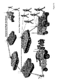
- FIG. 14 is an application of the Hybrid Mesh concept to a Public Safety embodiment.
- the node labeled 010 is a Stationary node on top of a light pole, in this embodiment.
- a mobile embodiment shown as labeled 020 is entering the building (arrow) such as when carried by firefighters. These mobile units are also called “breadcrumb” routers.
- the Mobile Mesh nodes provide connectivity to two-radio portable units worn by the firefighters in this picture. All firefighters are thus connected to themselves through a peer-to-peer mesh network shown as a thin line. They are also connected to the Infrastructure mesh backhaul through one or more connect points. This ensures redundancy in network connectivity.
- the broken link (labeled 060 , FIG. 13 ) is avoided.
- FIG. 17 indicates the modular mesh framework, whereby a four slot board, as shown in FIG. 16 , may be configured to provide different functionalities: Two radio Backhaul (BH) 010 ; three radios BH+AP 020 ; four Radio with BH AP and Scanner 030 ; four radio with Full Duplex (FD) using a coupled two radio BH 040 . Further, since the modular mesh framework always forms a tree, these nodes are part of a switch hierarchy, as shown in FIG. 5 .
- BH Two radio Backhaul
- BH+AP 020 three radios BH+AP 020
- FD Full Duplex
- FIG. 18 depicts how the installation software is tagged to both the radios and board characteristics. It shows a serial line connected to load the boot loader program, after which the Ethernet port is used to complete the software installation and branding process. Compiling the install program on the board it is intended to run on performs this function, thus creating a unique software image.
- FIG. 19 is a screen dump of the Flash Deployment software developed and implemented to ensure that software generated for the install of this board cannot be used by another mesh node.
- the software installation process begins, the software is compiled on the board it is intended for and the compilation process is unique since it is based on a number of unique factors.
- the software is generated on the board that it is intended to run on—to ensure that the software image cannot be used to run on another board, thus preventing both software privacy and dissuading theft of the mesh nodes.
- FIG. 20 shows that the Mesh Control Software sits above the Media Access Control (MAC) of the radio. As such it is radio and protocol agnostic, in one embodiment.
- MAC Media Access Control
- FIG. 21 shows how channel interference is dynamically managed in the logical two-radio system.
- FIGS. 22 and 23 introduce an embodiment bridging across diverse wireless medium using the example of an N-Logical wireless medium bridge, referred to as the “nightlight”
- the nightlight serves as both range extender and intermediary between device “chirps” and more conventional, IP based, communication devices and protocols.
- FIG. 24 shows the synchronization of multiple voice devices accessing the same wireless medium with a focus on the time for bulk receipt of packets that are shared among the separate devices.
- FIG. 25 shows a voice device talking to a dedicated voice radio and data devices taking to a data radio, with one phone 2501 , capable of taking to both 2502 and 2503 in one embodiment.
- the night light embodiment 2504 manages both voice and data transceivers, in the depicted embodiment.
- FIG. 26 depicts the dynamic collaboration tree for an exemplary supply chain application.
- FIG. 27 shows an isolated mobile network cluster and communication within it using VOIP phones.
- FIG. 28 through 29 describes an embodiment wherein isolated network clusters may converge with distributed DHCP services and inherent conflict resolution using randomized sub net address ranges.
- FIG. 30 through 31 depict the process of generating an OS less image for secure small footprint devices and an exemplary graphical programming environment for simple sensory devices, in one embodiment.
- FIGS. 32 and 33 depict device repeaters and range extenders.
- these devices are similar to clients, such as the soldiers shown in FIG. 15 . They provide blind repeating and therefore range extension for remote devices. They also serve as a redundant path, similar to FIG. 13 but employing a single physical radio. Thus, in chirp language, they are birds that repeat and relay a bird song in string of pearl configurations.
- FIG. 34 through 36 depict representative IP based “light” or low payload packets that may be used to transport chirp data over a IP based network.
- 802.11 packets are used as examples.
- Chirp data is encapsulated in such packets for onward transmissions, in unicast, multicast or broadcast modes, in search of flower/agents/tunes/subscribers interested in the chirp/pollen.
- chirp devices use such innocuous frames to transport payload—only chirp aware routers know how to recognize them as chirp packets and process their (secure) routing to appropriate agents accordingly.
- FIG. 37 through 38 map the equivalent slots/ports of wired and wireless switch equivalents as shown in FIGS. 4 and 5 .
- FIG. 39 shows how logical radio modes, Uplink (U), Downlink (D), Scanner (S), Access Point for Service (A) map to physical transceivers in single radio and multi radio mesh node embodiments.
- the joining of tree branches 3950 to tree trunks 3960 is aided by common routers 3952 .
- FIG. 40 is a simulation of a representative prior art mesh routing algorithm and its comparison to tree based routing of FIG. 4 .
- the thicker blue lines in FIG. 40 , 4040 denote the minimal spanning tree. Note the dashed lines have to be additionally recomputed for each node in prior art mesh routing. Performance deteriorates exponentially as O (n 2 ) where n is the number of mesh members.
- FIG. 44 shows the bridging function (as described in FIG. 43 ).
- Mobile node 4455 switches from “blue” 5.8 G backhaul to a “pink” 2.4 G backhaul.
- the sub tree beginning with mobile node 4457 is thus operating on a non-interfering channel/frequency/protocol.
- the static counterpart is 4460 .
- FIG. 45 depicts a “string of pearls” configuration of static mesh nodes.
- a mobile mesh node traveling at 60 mph makes temporary connections with each node in the string. Switching from node to another is seamless and unbroken, as noted by the video output below. Note that this is raw video and did not include the efficiency enhancements described in prior application Ser. No. 12/625,365.
- the process is repeated with single radios embodiments, using logical radios. Bandwidth degraded along the string of pearls, as expected, but video output was still jitter free and unbroken, due to proactive Scan Control, FIG. 12 , Logical Radio abstractions and the benefits of O(n), tree based routing.
- FIG. 46 is reprinted from Ser. No. 11/434,948 (FIG. 10). It depicts the dependency of latency sensitive traffic to the network tree topology, specifically, the number of siblings in sub trees along the route to the destination node/parent/root.
- FIG. 47 depicts the use of a reserved time slot for transmitting bulked, latency sensitive data, in accordance with the protocol explained in Ser. No. 11/266,884, whereby clients remain silent during transmission in this time slot.
- the time slot allocations may be fixed or variable. In one embodiment it is dynamically managed by Collaborative Scheduling, 61/555,400
- FIG. 48 depicts broadcasts/streams restricted to a region.
- the region may be defined by geography, membership and mesh topology e.g. restrict the number of hops or sub trees. Further, the region may include directions: up/down or a set of turn by turn directions.
- An example of regional streams may include a section of the home, where only siblings of a sub tree need Note that backhaul bandwidth is not affected outside stipulated regions. Restricted broadcasting improves overall network health.
- FIG. 49 is effectively the reverse of FIG. 48 and is global: e.g. not restricted. Tree based topologies favor global broadcasts. Streams from the root are always downwards. While streams from nodes may be either, they are typically upwards. The majority of devices populate the edge of the network and their pollen is typically upward bound, necessitating bulking, exception handling and deterministic time mail delivery along the route.
- FIG. 50 depicts the Stream Reader, an agent authorized to peer into network router transmission and receiving packet queues, prior to their onward transmission through the network. Like Post office sorters, they identify and sort packets for scheduled deliveries, prune dead letters, duplicate messages etc. They also provide decoded outputs for Stream viewers, a custom GUI for the data. Stream readers may also forward output to other readers, mail boxes or messaging systems.
- FIG. 51 depicts a circuit diagram of Stream Readers and their associated Stream Viewers, wired together to provide a capability, in this case “feeding” a section of the composite view ports 5190 .
- the composite view port is back drivable since its connection may be to real or historical data.
- FIG. 52 depicts the adapters and API interface components that provide an extensible, open library of stream reader and viewers. This enables the rapid prototyping of custom circuits to provide specialized competencies.
- the view port additions enable human participation in managing the network health. This includes, through adaptor view ports, all assets of the network and their health.
- FIGS. 53 and 54 depict the published interfaces for the Network Manager Streams API and the Heart Beat Entity relationships, respectively. Together, they enable speedy viewport development.
- FIG. 55 depicts an embodiment of methods outlined in FIGS. 47 through 54 .
- FIG. 56 compares contemporary thin client, single control loop architecture to a dual control loop, with a membrane separating the two control loops but, through the chirp to IP bridge/membrane, there is bidirectional, pruned and selective traffic, based on collaborative scheduling of bus schedules in both directions. Note that the two control loops are working on their own frequencies but neither is waiting on the other, see also FIG. 46 . This predicates the need for a “hub”, e.g. Propagator. They also serve as bridges between the upper control loop, IP based and lower, tighter (low latency/isochronous) control loops preferably in more efficient chirp protocols.
- the overhead of converting raw, machine specific raw data to a more palatable device abstracted format is performed within the cloud in the single control loop model in one case, and delegated to propagators in the other.
- the lower control loop, between propagators and devices can be low latency/isochronous while the upper control loop can focus on more infrequent high level tasks: performance tracking, exception handling system updates (event based, low latency), routine hourly reports (periodic) etc.
- FIGS. 59 , 60 depict a publish/subscribe exchange/market supporting multiple devices and integrators each operating in their own private communities/but also part of the same logical exchange
- FIG. 57 through 58 depicts a burgeoning market place “exchange”, where the confluence of multiple sources of terse but potentially rich content streams, often in organic protocols occurs at propagator trees.
- the root node serves as the Chirp to IP bridge/membrane.
- Small data is progressively refined and pruned, in proactive manner, as data moves upstream, like salmon upstream.
- Chirp packets no longer needed are discarded along the way, thus managing content relevance. Since chirps are category based, the protocol handlers (on both sides of the membrane) are logically part of the same publish subscribe bus system, with buses operating at different schedules.
- the distributed system manages the bus schedules to ensure control loops at all levels are operating without disruption.
- An Analogy would be nation wide bus services involving both greyhound and county run bus services collaborating on bus schedules to minimize overall delay, based on current traffic supply/demand.
- FIG. 59 is a example of a small “exchange” of multiple data streams, operating on different, non interfering wire-less media.
- the “vital signs” Integrator is fed exception and periodic, non urgent pruned data from the propagator.
- the exchange between device and integrator is managed by having two segmented control loops, maintained by the propagator.
- FIG. 60 is an example of a proactive control system, operating on the confluence of both local and external data publishers.
- the propagator picks up multiple sensor streams, from a grid of diverse sensor types.
- Local Integrators/Agents residing in the propagator can quick discern patterns and overall state of a large area—since small data is being generated and shared across a local mesh network, see FIGS. 57 through 58 .
- Local data streams are consolidated to provide a composite view of the region of interest. This feeds a second control systems where big data publishers provide a more global perspective.
- weather forecasts predicting rain can cause the cloud server to direct the propagator network to direct which section of the corn field need additional local irrigation.
- FIG. 61 depicts the simple circuitry needed to mass manufacture very low cost, low footprint, light “pollen” generators.
- FIG. 62 depicts a first layer, rudimentary small data generator, where sensor fusion/consensus generates early warning signals with fewer false positives.
- the propagator and first layer integrator may be bundled as one device, servicing both single and multi-sensor subscribers in the local meshed network and beyond.
- FIG. 63 depicts a four leaf clover like propagator, with 4 independent transceivers, 90 degrees rotated from each other.
- the 4 transceivers may be logically assigned uplink, downlink and scanner functionality, based on where the clients and relay node parents are located and the current network routing priorities.
- the transceivers may be dynamically and logically reassigned as the network topology changes or as clients migrate into and out of the network. Note that, as other 4 port devices depicted in this application, there is only one uplink per the 4 leaf clover design—it is scalable O(n) tree architecture. One layer is shown—overlays of such devices cover different wireless transmission media (e.g.
- Infrared LEDS for Chirp and Bluetooth for IP networking A stack of such four leaf transceivers than thus service both Chirp and IP clients, including other propagators. Since routing is lineage based, siblings are easily recognized. Ability to see siblings provides fail over redundancy with minimal change to routing tables. This engenders stable, healthy networks.
- FIGS. 65 through 67 relate to the collaborative scheduling engine described in previous applications.
- FIG. 65 is the starting condition where each task is taking just a little longer than expected.
- the usual first in first out queue, see FIG. 66 results on excessive delays further out for entities at the tail of the queue.
- FIG. 67 employs collaborative scheduling to balance out and maintain overall “customer satisfaction”.
- two tasks are “stacked”, because they are contending for the same resource a portion of the time. Stacking implies more resources are needed. When the resources are limited must be shared, this is not an option.
- Collaborative scheduling shifts the two tasks in opposite directions in time, to remove the stacking. The shifts are based on shifting those task start/end times within “Customer Satisfaction” constraints defined by the blue/red ranges for the task. An application to timing transmissions between chirp devices and their routers/bridges is discussed.
- FIGS. 9 , 22 Bridging across Wireless communications media, FIGS. 9 , 22 .
- FIGS. 4-8 The scalability of tree based logical network and mesh architectures, FIGS. 4-8 , 24 - 26 .
- This section applies those methods to transport “chirp” broadcasts akin to VoIP packets from “chirp” device networks to co-existent and incumbent IP based network devices and protocols.
- Emails are sender oriented. Sender oriented communications are intended to be read by stated intended recipients only. It is not lightweight: it contains destination addresses and encryption so they are not tampered by hackers. They were historically point to point communications.
- IP based Routing protocols favor economies of scale in moving large packets, preferably with best effort only.
- QoS latency/jitter/assured delivery
- IP protocols extract a premium.
- Small packets are also charged a premium because the “standard” minimum packet size was not designed with them in mind. Traveling inside the minimum size, they have to pay the same price in transmission time and bandwidth requirements as the “standard” minimum.
- FIGS. 10-12 are discussed in referenced applications. Filling the packet container reduces the “price” per VOIP packet and also ensures reliable (assured latency/jitter) delivery. Without containerization, client capacity rapidly deteriorates, FIGS. 10-11 .
- the IP highway is not suited for short chirp like devices, whether they are VOIP packets or other types of small-payload transmissions.
- receiver oriented security enables pollen to be lightweight (terse) and carried far by even small low power winds. Further, pollen is reasonably patient or latency indifferent. As long as winds appear within pollen season, spring will occur. Light weight chirps/pollen are thus secure and lower Total Cost of Ownership (TCO) based on their lightness and “patience.”
- TCO Total Cost of Ownership
- IP based routing services require customers to choose their “value” between extremes:
- FIGS. 10-12 teach methods related to which packets need to leave on which bus and how often those buses need to visit the bus station (polling frequency).
- FIG. 24-25 focus on what would be the best times for pollen to “arrive” at the bus station or other “wind” transport for onward routing.
- “Chirps” are short duration and terse commands/status messages, primarily for machine to machine (“M2M”) communications in home, factory or outdoor enterprise networks. M2M communications are purpose built and terse. Chirps from a TV remote to a TV, for example, has a limited but adequate word vocabulary to be able to control the complicated communications sources used by the television to change channels.
- M2M machine to machine
- FIGS. 6-9 , 13 - 15 , 22 - 23 core issues of dynamic channel interference remain: there are still limits to the number of available “channels” despite extending the usable channel list. The challenges addressed by previous work, still remain real and relevant.
- IP based devices operate on CSMA/CA protocols. Using random back off, radios “sense” collisions and, in decentralized manner, avoid collisions. As an analogy, there can still be two or more people talking at the same time but it is minimized because most people are being polite and waiting their turn. In the event a packet did not go through, it is retried but this is the exception not the rule.
- the protocol is robust, scalable and ubiquitous for IP based wired and wire-less traffic. Thus an “agile” and “polite” competent networking protocol already exists.
- Listening and avoiding interference in proactive manner is also referred to as “agile” and/or “polite” systems.
- Agile is analogous to one dance partner compensating for the (random) clumsiness of the other.
- Polite refers to listening and then avoiding interrupting others (collisions) in conversations.
- Chirp devices and protocols leverage this politeness/agility of IP stack based devices to coexist. If Chirp durations are very small, many that occur during IP protocol enforced silent periods have no adverse effect. Further, chirps transmitted at the same time as active radios, may not significantly affect IP based traffic if they are so short that radios can adaptively manage the chirps as noise.
- Low cost chirp devices can be very simple, in one embodiment. Some simple chirp device, like birds, chirp “blindly,” with no consideration or verification of whether the chirps are heard or not. Multiple such blindly chirping devices can be chirping at the same time, resulting in retries and interference. These (repetitive) deadly embraces are avoided by randomly scheduling “blind” chirps by the device transceivers. This is a simple fix, used in one embodiment.
- IP protocol based wireless transceivers operate in the same frequency domains as chirp devices.
- these chirps are treated as random and transient noise. It is adaptively filtered out using Automatic Gain Control, Error Correction, Noise cancellation, and other methods, while the Wi-Fi radios are sending messages other than chirp communications.
- IP based wire-less or wired transceivers As more chirp devices join the network, their random chirps are like white noise for the IP based wire-less or wired transceivers. These adaptive IP transceivers adjust. It is their modus operandi. At the worst case, one or two IP based packets may be retried, but IP throughput is not appreciably affected. It is certainly no less affected than having a nearby Access Point (AP) producing channel interference. This is because chirp transmissions are short, by design. Thus, short random chirps, are inherently capable of coexisting with legacy incumbent wire-less (or wired) transmission protocols.
- AP Access Point
- Chirp packets contain information of their intended transmission pattern.
- the Access point can thus, anticipating a chirp, preempt contention by sending out a CTS “incoming” notification to its IP client stations, thus clearing the air waves.
- sophisticated chirp devices with listen/see capability can be directed by chirp router embodiments to modify transmission times and channels, see embodiments FIGS. 22-23 .
- Advanced chirp-aware routers with chirp equivalent of scanning radios in one of the slots, see 030 , FIG. 17 may also scan the RF environment.
- the AP can then direct some chirp devices to schedule their chirps to “avoid” or “cluster” with other concurrent transmitters. Clustering changes the transmission times of listen capable chirp devices to engender sequential chirps—and the AP can schedule a bulk concatenated CTS “incoming” warning to its IP clients.
- Ser. No. 11/266,884 teaches methods so custom VOIP phones and advanced chirp inside (chirp aware) device equivalents, which schedule their chirps to avoid collisions with each other and downstream bulk broadcasts from the AP, as shown in the embodiment of FIG. 24 .
- Chirp aware devices are capable, therefore, of being agile and polite within the network environment. Instead of random blind chirps, these proactive devices are listening and timing transmissions to be collision free with bulk transmissions back from the bridge router, FIG. 23 , or other collaborating chirp inside devices (e.g. TV, camera etc), FIG. 22 .
- Collaborative ant like agents schedule small chirps to avoid each other or to cluster in dynamic alignment with resource stacks taught in Ser. No. 13/571,294.
- Chirps are small and repetitive, analogous to small VOIP packets. IP does not favor small repetitive packets, see FIG. 10-12 . Like VOIP packets, chirp packets will be repackaged for bulk transmission when bridged from Chirp networks to IP networks, FIG. 12 , 22 - 23 . Small Chirp packets, like small VOIP packets, will be routed/distributed efficiently using pruned broadcasting methods as described in Ser. Nos. 12/352,457 and 11/266,884. In one embodiment, Chirps transmitted to IP based networks are containerized and under router management: they cannot individually create broadcast storms.
- the mesh control layer provides “radio” and “protocol” agnostic mediation. These words were not restricted to either Wi-Fi radios or IP protocols, as indicated above.
- the system provides a common mediation layer for all disparate forms of mesh networks that are bridged together to form one logical meshed and scalable network topology, FIG. 22 . Only then can a logical mesh network exist, across multiple frequency and protocol domains.
- the wire-less radio and protocol agnostic mesh control layer ( FIG. 20 ) includes mesh networks different from IP based protocols as shown in FIG. 9 . A new protocol is “chirp” based. It is specifically designed to minimize interference with existent and incumbent network protocols.
- the mediation layer supports it, in one embodiment.
- chirps may be efficiently and reliably transported up/down the (bridged) logical network tree, comprising of both IP and chirp networks, see FIG. 22 .
- Ser. Nos. 12/352,457 and 11/266,884 teaches methods for VOIP, to enable chirp like broadcasts from chirp like device networks to be efficiently repackaged to travel on existent and incumbent prior art IP based Network devices and protocols.
- a temporary broadcast storm despite the unwanted effects of allergy season, is tolerated. It is the only time-proven method of ensuring sufficient pollen is “heard” in Nature's chaos based ecosystem. The storm is intentional and over provisioned but effective. It is undirected, so it covers all bases.
- Pollen is lightweight. That works in its favor. Small gusts of wind appearing randomly move it along. It may need multiple gusts of wind, like multiple relay hops in a mesh network. Nature does not know where ‘subscribers” are. Scatter shot approaches cover large unknown subscriber regions.
- chirps are light weight and receiver oriented. They do not have destination addresses. Like school children boarding a school bus, they must be directed to get on the “yellow” bus/wind. In one embodiment, at each bus stop along the way, they need to be told which next bus to board.
- the edge router FIG. 12 , 23 manages bus arrival and departure times and also getting the chirp/pollen bulk containerized and ready for each bus trip. Where containers go is driven by the “clients”: it is directing pollen to interested parties only. This is a more directed beam vs. scatter shot.
- the yellow bus routes mark pockets of subscriber interests, available for trend analysis, if desired.
- pollen/chirps are delivered to the subscribers interested in them/waiting for them, in a timely manner.
- the chirp routers manage pollen/chirps getting on the correct “yellow” buses and bus departure schedules etc.
- Buses leave at regular intervals to help schedule when a container of chirps arrives and leaves at each bus station. They are a part of the mesh network support infrastructure for chirp travel. Their frequency of arrival is driven by the polling frequency (e.g. 20 ms for VOIP phones). It will vary depending on the chirp device nature and urgency per methods taught previously, FIGS. 12, 24-25. Scanning and polling frequency is adaptive, per methods taught for mobile nodes, Ser. No. 11/818,899.
- pollen bus depots (the routers) schedule bus size and frequency of departure (polling), as well as time spent waiting for data to collect (minimum queue), and other variables in certain embodiments.
- Collaborative scheduling agents in some embodiments, ensure global supply chain alignment of supply/demand using simple concepts like “avoid” and “cluster” to ensure appropriate use of bandwidth resources and prevent “stacking”. Ser. No. 13/571,294 et al. teaches scheduling collaborative agents in control systems.
- QoS equivalent services are dynamically managed in a receiver oriented network. This is a departure from Prior Art, when sender oriented IP packets must declare their QoS requirements a priori, and QoS requirements are blindly enforced along the network path at significant added cost.
- FIGS. 27-28 Subscribers are stationary and mobile. Hence routing is a moving target Mobile intermittent connectivity (not “always-on”) is supported, FIGS. 27-28 .
- the client is currently unavailable and messages are delivered to a trusted community mailbox.
- the subscriber may request temporary mail holds or re-directs, akin to when people relocate or move residence.
- Chirp routers are made aware of updated subscriber locations, by secure authenticated means, in one embodiment. They maintain a community mail box and support addresses for otherwise anonymous but authenticated subscribers. Thus chirp routers serve as post offices, part of a meshed postal service network infrastructure, with coexisting IP and Chirp publishers and subscribers, see FIG. 22 .
- chirp routers may also be requested to manage a family of devices. For example, in one embodiment, all kitchen appliances broadcast chirps towards the kitchen router, which is a night light in one embodiment, FIG. 23 .
- the kitchen router is authenticated to communicate with a smart phone using secure IP based networks in one example.
- the smart phone is informed by the router/nightlight which processes chirps incoming from the new devices.
- Chirp routers perform these routing based services based on chirp signatures, described herein.
- routers recognize chirp “colors”/signatures. Also, in one embodiment, they know where (authenticated) subscriber destinations are. Hence, only they have the means to connect the two pieces of data and to dynamically direct chirp/pollen containers to subscribers/agents/mail boxes. Even if they do not know where the agents are, managed multicast and broadcast techniques will be used to find the “flowers”, described presently.
- pollen/chirp “publishers” are directed to “subscribers” with potential broad interests in multiple types of pollen/chirps. In the trivial case these interests maps to multiple individual active subscribers IP mail box addresses. Efficient, pruned broadcasting taught in Ser. Nos. 11/266,884 and 11/084,330, addresses those specific needs. In the less trivial case, the “destination” address is a movable target, both literally and figuratively.
- communications are a movable target because of dynamic consumer needs.
- Demographics of the communication network comprising of both human and machines, is in flux at all times, as shown in the embodiments of FIG. 13-16 and FIG. 26 .
- edge routers embodiments FIG. 23 to move pollen/chirps efficiently, are also in flux.
- a distributed control system monitors the environment, in one embodiment.
- Dynamic Load Balancing taught in Ser. No. 10/434,948 included switching data paths to less congested parent nodes. This in effect also changed mesh topology. This was needed because latency and throughput tradeoffs were being made.
- the traffic is (reasonably) latency indifferent, store and forward community mail boxes provide some relief to the deluge bound to a congested node in transient congestion situations.
- node congestion levels may be communicated to adjacent “buddy” nodes, who then “hold the mail” until toll costs are lower. This exemplifies proactive re-scheduling, driven by dynamics of toll/hop costs, Appendix A.
- Subscribers may also request redirection. For example, chirps from all Sony TVs in San Francisco, received between 8 am and 9 am today have been containerized. They are scheduled to be sent to a customer service center in Japan. The largest subscriber “blob” is in Japan. However, network connectivity is interrupted due to a natural disaster which has hit Japan. Those containers now need to be routed to the Customer service center in India.
- the present system determines who should get these requests, and does so on the basis of several variables—it is situation dependent. There are associated costs with different options. Finally, the device or machine has an owner with his preferences and overrides. One-to-one correspondence systems are too simplistic.
- the receiver oriented approach presents a simple solution—chirps or pollen is simply redirected at each bus station/router along this route.
- the chirp routers and control system thus stays aligned with shifts in subscriber needs.
- dynamic publish subscribe is scalable.
- Publish subscribe is generally scalable. For example, radio stations have no upper limit on subscribers. Enforcing a re-evaluation of where subscribers are, at each “bus depot” along the route, ensures that it is both dynamic and scalable.
- Subscriber driven “winds of change” are engineered and coordinated: convoys of buses, carrying bulk pollen and their engineered clones, thus concurrently supporting multiple subscriber requests. They are like VOIP packets bound for multiple destination phones, like walkie-talkie phones. One publisher is simultaneously received by all listeners. Thus pollen and clones of them, expressly created to cover multiple consumers, board multiple buses, on different schedules and routes. The chirp routers create the clones, engineer these winds and collaboratively manage their flow.
- the sending router only knows enough to send the school children to first bus station address. It may not have knowledge of final destinations, which may be dynamic.
- the hierarchical architecture is similar to a post office hierarchy (county, city, country are the hub levels), but unlike the post office, the direction or “default” address does not convert the communication into addressed and sender-oriented transmissions. The mailing address is being inspected and changed, based on the current situation at each router/bus station, a departure from the prior art.
- routing policies may be specified.
- One “policy” is in place that all GE refrigerators provide a daily health status short “chirp” “color” (e.g. red, orange, blue, purple) forwarded to GE appliance service centers/subscribers. There are four such appliance region centers e.g. North, South, East and West. Based on the chirp signature and device location, directives running in edge routers “know” which bus load this pollen/chirp has to be part of.
- packages are bulk shipped to one central logistics hub, which manages the dispatches to other logistic centers. If packets need to be cloned to support multiple subscribers, they are, at forks along the path, in this embodiment. Further, VOIP like chirp packet cloning is managed by the router on a need basis, where forks occur—e.g. the container was traveling north, now is split into eastward and westward “half” containers and combined with other fellow “half” eastward and westward bound containers to form a more efficient whole container. Some chirp packets are cloned because it has both east and west subscribers. Thus, efficient repackaging and pruning of routing paths, as described in FIGS. 12 , 24 - 25 and 27 - 28 address multiple scenarios including mobile devices, temporal mesh network clusters and VOIP like schedulable periodicity.
- the destination of the bus is dynamic and so is its routing path. This is analogous to not just changing bus routing (e.g. an accident) but also end destination (e.g. hospital) based on the current situation and nature of containerized load. If the load is no longer needed, it is discarded mid journey. Round tripping, caused by static destination addresses, is avoided. Further Cloning at forking junctions ensures concurrent, low latency deliveries.
- the schedules for convoys of buses are adaptively managed by collaborative scheduling agents see Ser. No. 13/571,294 et al.
- Winds in nature are seemingly undirected broadcast storms. As in nature, seasonal, undirected and sporadic broadcasts are tolerable if time-to-live functions are adaptively managed at the control system level. This is more than just preset time-to-live or maximum hop count values instilled in IP packet header data. Macro level system control is needed so broadcast storms cannot perpetuate.
- the control system should monitor and modulate “decay” function and its PID control parameters and make changes to network topology accordingly, see FIG. 1 .
- An embodiment of the invention has implemented inherent Distributed Decay Functions that include time-to-live, heartbeat sequences, max number of relay hops, stop at “root” nodes etc. PID parameters and mesh topology change dynamically, to ensure network scalability and stability.
- Winds are a more amorphous concept. They are closer to broad agency announcement to address an Emergency Response involving sharing of diverse resources e.g. Joint Armed Forces embarking on a common mission.
- Convoys of chirp buses emanating from multiple locations are merging, dispersing and coalescing, driven by both publisher type and subscriber demands. They are generally directed to a concentrated location (e.g. New La post Hurricane Katrina). Note that multiple such “Hurricanes” can be occurring concurrently. Clustering and dispersal in mobile mesh networks was taught in Ser. No. 11/818,899, FIGS. 27-28.
- known subscriber requests are handled by scheduled deliveries, with varying level of urgency, latency, QoS etc.
- Winds serve a different purpose. They provide the capability to support coordinated efforts in sharing communication. One of many lessons learnt in New La was the inability to get different agency wireless devices to “talk” with one another. Winds address this.
- Interpreters may be safely installed in chirp routers. These are software/hardware/firmware. They can also be cards that fit in either the front or back slots of nightlight embodiments FIG. 22 , 26 . Event bound inter agency communication is thus supported by these embodiments. The inter-agency communication ends when the interpreter card is removed. Winds and other temporal relationships are now manageable. This is relevant to secure remote diagnostics and repair.
- Such routers may then, with appropriate interpreters installed, provide secure lingua franca capabilities between all types of devices in the network.
- the routers are also capable of real time communication and translation between IP based devices and chirp based devices.
- the chirp birdsong is now comprehensible to existing IP based system diagnostics and repair tools. No reinvention is needed.
- Chirp versions of machine independent programming languages like Java and Machine Esperanto will engender Human to Machine interaction as well as M2M communication.
- Chirp signatures define the broad property of the pollen/chirp. They do not have to be unique, just characteristic of a category of “bird,” some bird watchers (subscribers) are currently interested in. Chirp signatures provide one piece of the routing puzzle. Chirp routers are aggregate subscriber aware, on a real time basis. This provides the other piece to the puzzle. For example, the chirp router, in one embodiment, includes a data stores of how many (redundancy), how often (frequency) and suitable directions to engineer the buses needed to move current inventory of chirps. Scheduling buses is a collaborative supply and demand logistics exercise with dynamic alignment to prevent stacking, per methods taught in Ser. Nos. 11/266,884, 13/571,294 et al, FIG. 26.
- Chirps may be parallel and/or sequential transmissions. They form signature patterns and payload patterns. The signature patterns are needed by the edge routers to categorize the type of pollen/chirp and route it to appropriate subscribers. Subscribers exist on both chirp and IP based networks.
- the diesel generators in a community network wish to schedule a mass repair visit. They need to share information. They can certainly send their data to the IP based customer service center in India. However, for each diesel generator that is a round trip from chirp network to service center and back. If instead, an embodiment of the invention is used and the generators are capable to chirping over a meshed chirp network, FIG. 22 , then based on chirp signatures, diesel generators can recognize each other and use collaborative agents internally to perform needed scheduling for repairs. This was also discussed in Ser. No. 13/571,294.
- Signatures are thus key to both intra-network and inter-network chirp payload propagation and routing, in one embodiment. Further, chirps are also temporarily stored in community mailboxes, in transit in times of congestion or network non-availability. To get a sense of the “demographic” of passengers awaiting transit services, chirp routers inspect signatures and accordingly arrange appropriate transit services (e.g. small bus or convoy of buses).
- appropriate transit services e.g. small bus or convoy of buses.
- signatures are a distinctive pattern of ringtones.
- Each chirp/ringtone is based on multiple variables e.g.:
- a two chirp/ringtone signature has two chirps/ringtones in sequence.
- Each ring tone can include one or more transmitters.
- the two chirp signature has four distinct states (0-0, 0-1, 1-0, 1-1).
- the device is therefore capable of three distinct non trivial (not all zero, or silence) states for each transmitter. (2 2 ⁇ 1).
- the number of possible signature sequences for simple on/off transmitters is (2 M ⁇ 1), where M is the number of ring tones in the sequence.
- a three ring tone signature sequence has 7 distinct non zero variations (2 3 ⁇ 1).
- S total S 1 *S 2 *S 3 . . . *S t
- S total Total nontrivial unique signature “tunes available with t active transceiver pairs.
- the ringtone concept may be applied to other non-audio frequency domains.
- the ringtones may also include multiple simultaneous send/receive on diverse “channels” (e.g. infrared and audio), in some embodiments.
- the composite ringtone is analogous to a musical chord: it's a “richer” tone.
- the chord carries more information for multiple uses e.g. redundancy, error correction and multi-level security, denoted by number of chords and receiver capability to receive them some or all the tones.
- the “public” message may be simulcast with a “private” message decipherable only by devices with capable receivers.
- enhanced services may be provided to select customers, by providing them the appropriate chirp equivalent of a TV cable decoder that, with installed firmware, provides access to more TV channels in the “bulk” broadcast.
- ring tone chords from different devices provide two-level authentication system capabilities.
- a police car will not start unless the policeman and his partner are safe in the car, determined by synchronized chirps from both their smart phones.
- the phones are secure in that only the authorized users have the correct access codes so stealing the phones renders them ineffective.
- Chording thus provides multiple security layers.
- Ringtones are one example, easily available on smart phones.
- chirps can be “rich” in information even if it is a short, unobtrusive burst.
- smart phones and other computers are thus multi-lingual devices, capable of translating chirp chords from Wi-Fi, Infrared, Audio (ringtone) and light patterns (camera flashes and photo image analysis).
- the smartphone software consists of one or more apps.
- the apps are loaded on these computing devices also provide translation mechanisms to understand what was said in chirp languages and what to do with the payload data.
- the chirp signature like a bird chirp, is essential for this translation and categorization—it tells us what type of bird is speaking Note that the apps were downloaded through secure and authenticated sources via standard IP.
- chirp signatures may also share some chirps common to the flock.
- higher level systems such as the embodiment of FIG. 26 , know where the chirp devices of type “Yellow bird” are and their states. Demographic data is readily available.
- Chirp routers employ in one embodiment the chirp equivalent of the distributed DHCP server based IP addressing scheme with inherent conflict resolution, as shown in the embodiment in FIG. 29 .
- devices are given names, randomly chosen, but with inherent conflict resolution. These names can be changed frequently by the router for all but the simplest “blind” (no listening) chirp devices.
- Blind devices in one embodiment, like garage door openers, have simple means for identification variation, such as DIP switch settings so their timing and/or channel are modifiable by the user, as directed by the routers governing the devices.
- Sibling names must be distinct but need not be unique, in one embodiment. If a device name is distinct, amongst its siblings, then tree based logical routing is sound. As an analogy, Eric, child of Paul, child of James is distinct in a tree based topology from Eric, child of James, child of Paul. The routing table entries and routing paths for the two Eric's are distinct: James ⁇ Paul ⁇ Eric and Paul ⁇ James ⁇ Eric. Note that in this approach, the “lineage” is exploited to provide context/delineation between two devices of the same name and in the same network.
- chirp routers will either first attempt to change the name (for embodiments where the chirp device name is programmable) and otherwise will notify the user to change device signatures, (e.g. dip switches for garage doors) or move them to another chirp access point/router.
- chirp devices take direction, in one embodiment. That direction comes from routers and tune directives from trusted “mother” agencies. When a chirp signature or chirp language/protocol has been compromised, the device may be taught different birdsong. “Mother” chirp directives may rename a device and switch from one language to another. The languages may be closely equivalent e.g. dialects of a purpose built machine Esperanto. Changing names and word “look up tables” thus provides additional enterprise security.
- humans have multiple forms of secret data in handshakes, nods and winks intended for specific audiences.
- Certain groups have a secret handshake that provides intended recipients with additional information. Neither party shaking hands may have prior knowledge of the other. They are shaking hands in broadcast mode, visible to everyone. In fact the person initiating the handshake may not even be aware that he is communicating special information—it is simply the way he always shakes hands.
- the security is “genetically encoded.” The onus shifts to the recipient to decode the message, based on secret signatures they were taught to look for.
- security infrastructure requiring encryption at the source is no longer essential, since the message signature is already encrypted and only intended recipients can decode it.
- the publish/subscribe broadcast may be “open” and hence lightweight.
- how communications are understood may depend on multiple levels of security. Adding more transceivers, operating in diverse frequency bands, is an effective way of sending partial messages, and is used in one embodiment of the system.
- decoy signals are be sent on one or both “channels,” in one embodiment, that are being watched. Only devices that know the secret handshake, can piece the “real” message together, removing the decoy components of the transmission.
- Decoders can access the entire information, others have limited access. Thus, despite their simplicity, even smart phone ring tone chirps are difficult to decode, especially when there are multiple concurrent independent transmissions. See embodiments shown in FIGS. 7-8 , 23 , which are the equivalent of musical chords.
- Changing the bit mask using “dip switches”, for example, can change the bit mask and therefore signature “tunes” that the chirp device will listen for.
- the owner changed the signature “tune” for his chirp device.
- Single tune for single chirp device In one embodiment there are three chirp devices on a local network (wireless or wired). They both have three ring tone signatures and five tones for payload data for a total of eight ring tones. It is unclear to snoopers, which machine is being addressed when a single eight ring tone tune is sent.
- FIGS. 19-20 , 30 - 31 relate to methods previously taught to remotely manage secure devices.
- Chirp devices reside inside a local network is not public knowledge. Their routing is a function of both the IP address of their parent chirp node/router and chirp device signature.
- Chirp Signature, protocols, internal routing information is accessible only within the local area network and restricted access to authenticated members only, typically router embodiments that manage the devices e.g. night light, smart phones et al.
- routers may employ a distributed DHCP IP addressing scheme with inherent conflict resolution, FIG. 29 . They are capable of autonomously changing their current IP addresses and privately communicating this way within their local IP networks. They are also internally capable of changing IP addresses for their IP clients and those IP to chirp tunnels that connect chirp devices to IP addresses. Finally, they may also request listen-capable chirp devices to change their “names” and even teach them a new equivalent vocabulary, in one embodiment. Thus a traffic light swaps “green” for “red”—only the router or its agents knows that red now means go.
- an IP based tunnel/socket needs to be established for real time interaction with a chirp device, it is the router, using DCHP, that makes a temporary IP connection available, per methods taught for temporary and mobile mesh networks, see Ser. No. 12/352,457. Thus all “contact” is router managed and the router is secure in several embodiments of the invention.
- Pollen is moved based on its chirp signature or its explicit naming of an agent/flower. Where it goes is managed by the router. Only the router network knows both pieces of the puzzle (sender “color” and subscribers for those “colors”). Further, in a receiver oriented world, only the destination address (e.g. Agent-ID) need be known to the router. It cannot decipher the contents. Only subscribers/agents at the final destination know how to unlock the pollen's message.
- Agent-ID the destination address
- Temporal ring tone sequences generated by the routers, may be added to chirp signatures. At each hop they may be replaced by another (thus only adjacent routers know each others keys). Or network level keys are distributed, by IP, from the Enterprise and their agents. They are known only to those in the trusted network and are periodically changed. Without this additional key, all chirp communication is unintelligible. A simple 2 or 3 light flash or ring tone sequence, sent by the routers, thus suffices in one embodiment. If the routers are using beacons to inform chirp devices of their presence, then this data could be in the beacon chirp. Since it is a temporal key, hacking it has limited value. Further, the chirps do not need to be encrypted on a packet basis. Container level encryption may be sufficient, for those embodiments, thus reducing security key distribution complexity. This reduces the complexities of large scale security key distribution and its management.
- Secure interpreter cards offer a portable form of device security for one embodiment. Machines chirp terse status and error codes. These are received by a meshed network of night light routers or their agents. Removable Interpreter cards may be installed in the slots, FIG. 17 , 22 , 26 . Chirps can be interpreted and translated at multiple locations of the logical mesh network tree, including at the router itself. Further, the cards and their agent may have limited access privileges to the chirp data. Hence multiple agents/cards may be needed to get the full message decoded.
- secure software upgrades to chirp devices and the router follow the same method taught in Ser. No. 11/088,330, see FIG. 18, 19 and in Ser. No. 10/434,948, FIG. 30,31.
- Dongles may be used in the router slots or USB hubs to provide access only when inserted.
- An interpreter card in one embodiment, is inserted in one of the many slots (front and back) of the night light or router, FIG. 16 , 17 , 23 26 .
- the end user removes the cards.
- the “card” could also be a proximity chirp from an authorized device e.g. smart phone or dongle on the end user's key chain. When that chirp is heard, chirp routers are active.
- the same security card is used at a second location, such as at the end user's office, to perform similar interpreter functions.
- secure communication is portable across home and work environments.
- the smart phone suffices as the “card.”, engendering secure voice and data communications, authenticated by smart phones at both end. Since the mesh nodes/routers also manage regular IP traffic, both types of devices are accessible to the card, for secure inter-device communication.
- interpreter cards are used as a common home/office entry key in these embodiments. Further, the same card may have a separate section that filters out chirps from unfamiliar or unauthorized devices. It is then also acting as a firewall for both chirp and IP devices. Multiple cards, working together, can support complex collaborative efforts, involving both humans and machines, FIG. 26 and described in the associated application.
- Machines in contrast, may also have a lot of data to report—like a core dump—but this is the exception, not the rule. Most of the time simple red, green or orange “chirps” suffice. Further, since machine states are limited, small vocabularies are adequate. For example a color based language can concisely communicate many shades/hues/meanings tersely: complex shades of red sent from a single LED can communicate a lot tersely/swiftly, without lots of words.
- Chirp device communication may be short (for coexistence) but rich in meaning.
- the devices are also capable of faster parallel communication.
- a data byte is a sequential ordering of 8 bits of data.
- a serial port transmits 8 pulses sequentially.
- An 8 LED parallel port on the other hand, “chirps” once. Advanced LEDs or audio devices therefore transmit, in parallel, large packets of data in one chirp. The chirp bandwidth is dependent on the resolution of transceiver to send and decode the “parallel” port data.
- TCP/IP like protocols may be implemented to resend data but it defeats the objective of coexistence with verbose (sequential data) IP dance partners also operating in the same spectrum. Instead, like birds, repetitive chirps ensure that at least a few chirps are heard. Also, like pollen, the embodiments of this system err of the side of sending more repetitions in the hope that at least that a few bear seed. This implies, like Allergy season, a timed broadcast “storm.” Further, like pollen, the data is receiver oriented, so, like bird chirps, everyone can hear it but only intended receivers can decode it. Pollen can travel light.
- Chirp vocabulary is driven by what the devices wish to convey and since it is receiver oriented, it can be as simple or complex as needed. However, if chirps are using the same frequency spectrum, these chirping “radios” must broadcast short bursts, repetitively and randomly. “Chirp aware” devices, unlike their advanced Wi-Fi and Bluetooth cousins, emulate limited agile/polite behavior.
- Tunes are used as signature patterns and data payload. Or a concatenated and encrypted version of both, where encryption includes delayed transmission as in syncopation.
- two tunes are really a jumbled version of one secret handshake, where even the silence may have meaning, known only to intended receivers.
- Bird chirps respond to changes in the environment. For example, a cat walks through the park. Our eyes follow it. Our ears notice how the chirps follow the cat's motion as it moves from one tree to another. Chirp tunes will change both in the sequence of tones and their intensity. We therefore, as snoopers, may be able to discern activities common to the same consensual domain because we are matching patterns in two different sensor domains (eyes and ear). We are putting two and two together. Multiple sensor fusion drives our inference engine.
- the cat may visit different parts of the neighborhood. There are trend indicators there but the sampling duration may need to be months to accurately pin point “affected” regions.
- the quantity of data to be analyzed is considerable. Some may need to be stored and reviewed later by the big data analysis engines that are predicting trends based on past history.
- the night light routers of one embodiment of this invention are like node branches in a park of other trees and birds.
- the router hears chirps of birds in its network of branches.
- the router simply has to know which subscribers care about which chirp signatures and arrange for buses or “winds” to carry the chirps to them.
- it is also a hub for its bird subscribers.
- it provides disembodied intelligence and storage for these simple devices—like holes in its trunk for nests.
- Each tree and its branches form a root and relay mesh network.
- Each node in the chirp network mesh tree is a logical first level filter for interpreting small data birdsong.
- Chirps include signature (e.g. like device names) and payload. Payload and signatures are melded to form tunes, in one embodiment.
- Tune payload may include short directives (scripts) sent as series/parallel pattern of chirps e.g. encryption, security signatures, data payloads, commands, data requests, software upgrades or real time diagnostic conversations.
- chirp devices and remote customer support centers establish a real time tunnel to talk in secure chirp languages, in on embodiment. In other embodiments, they even switch languages and continue the conversation easily—recall that machine states are terse and purpose built—their vocabularies are concise and therefore can be remapped to other “colors” or ringtones easily.
- Chirp directives are called tunes because in a receiver oriented world, only specific devices can “dance” to the “tune”—those that know the secret handshake. Tunes are (secure) agents that know bird speak. Further, end devices are purpose built and OS-less, FIG. 30-31 , in one embodiment. They dance only to specific tunes from “mother.” In some embodiments, the system components may be capable of “changing their tune” (e.g., mode of operation) based on directives from the “mother” or “mothers.” At any point in time, however, these tunes are ant-like collaborations: simple robust stimulus-response pairs. Like traditional get-set protocols, each tune has a specific dance partner.
- Tunes typically perform simple tasks. They are ant like in abilities—a tune is not complex construct like a song. However, working together, they perform complex tasks, or complete songs, like super organism e.g. ant hills.
- tunes/agents intelligible only to authenticated chirp routers, may also contain application specific inference engines as described in Ser. No. 13/571,294. In one embodiment, they are interpreters for encrypted “short hand.”
- the kitchen night light router is directed to forward only exceptions: no news is good news.
- An installed tune states that, as long as at least one chirp is heard and it is not a red flag, the router does not forward it.
- Another installed tune/ant, for another subscriber states that, at midnight, 24 stored chirps should be sent, so it may “plot” the hourly pattern. This “tune” uses local storage and time stamping, heart beat sequence numbers etc., see Appendix A.
- Other ant-like tunes may include post office like services: hold some mail for a period of days but forward others, discard others etc. A variety of conditional transport mechanisms are thus supported.
- QoS equivalent tunes may drive bus schedules and polling frequency, based on pollen types (chirp signatures) and their subscriber size, urgency and interests. Note that all the heavy lifting is at the router—the end devices are still thin client.
- FIG. 26 may include collaboration from ant-like tunes operating on other routers.
- the a router having a battery backup the kitchen night light notes no chirps were received from kitchen appliances in the last 24 hours.
- the router is aware that it is running on battery backup and that chirps were expected at regular intervals.
- a collaboration tune request that the kitchen night light confer with the living room night light embodiment, a Samsung TV via the power line network.
- the Samsung TV confirms that its devices are fine. Bayesian Inference and causal reasoning engines, correctly infer that the kitchen fuse has blown. If so, further causal reasoning indicates that perishables in the GE refrigerator are suspect.
- the home owner is informed via his smart phone. No repair reports are made, other than to notify of a potential overload condition.
- application specific intelligence at the chirp router level reduces customer support overhead and false alarms.
- Simple ant-like collaborative agents, working together engender complex reasoning from simple messages or even the absence of simple messages.
- packet cloning along a route is managed by each router on a need to know basis, in one embodiment.
- a fork is needed is event based, since the publisher-subscriber relationship is dynamic and transient. Subscribers may direct a Mother (root) node to remove some of its publishers from the “follow” list. Some, en route, will be removed at the next bus stop.
- a dynamic bus schedule based supply and demand alignment is constantly taking place—e.g. containers traveling north as one convoy, now split into eastward and westward containers and combined with other fellow eastward and westward bound containers to form a more efficient bus convoy.
- efficient repackaging and pruning of routing paths as described in FIGS. 12 , 24 - 25 and 27 - 28 address multiple scenarios including periodic chirps, mobile device communication and temporal mesh network clusters.
- QoS etc is dynamically defined by the subscriber and their agents (e.g. Tunes) Recall there is no static QoS value inherent in chirps, vs. for IP packets.
- Chirp pollen are simply directed to the appropriate “yellow” buses, from one bus station to another along their route to subscribers, Only Chirp routers within a local network know bus schedules and/or if a chirp packet was placed on a bus. Further, this type of data may be accessible only via secure IP based protocols, Malicious or malfunctioning devices, either chirp or IP, cannot manipulate device routings because these are event driven and dynamic. Rule driven event based systems are hard to “crack”—explicitly stated bus schedules don't exist, so cannot be “stolen” or manipulated.
- Routers are intermediaries between “small” data publishers and their “big” data consumers (machines and humans). In addition to routing, authenticated routers serve as distributed “big” data agents. Interpreter “tunes” correlate patterns and map different types of “events”. Big Data tunes, resident on the routers, monitor chirps and correlate “cat events” to corresponding birdsongs/tunes in their tune pattern library.
- the same small event feeds multiple complex event analysis and prediction engines. No one single small event is significant (and can be missed), but a swarm of them is a noticeable trend.
- the interpreters at the router nodes are data sieves/filters and in effect are also virtual “rich” chirp publishers to subscribers above it in the information food chain—feeds on data to generate actionable intelligence e.g. trending.
- the multiple small event chirps may feed into an interpreter that chirps a simple yes or no, terse but rich” in content. This data “richness” is possible with interpreters residing at edge routers (both root and relay nodes). Inference Intelligence is distributed with collaboration between the layers, all the way from edge routers up to core routers—big data analysis systems. A hierarchical, distributed tree based collaborative control system emerges, as the embodiment shown in FIG. 26 .
- Communication can thus be both terse and rich throughput the collaborative ecosystem. It can be sporadic, intermittent or periodic. All of this drives control signals in an adaptive distributed communications and control network, FIG. 1 , 26 .
- Some chirp devices use rich chirp shorthand, periodically, like VOIP packets, to communicate periodic updates or participate in a remote diagnostics session.
- time delay between transmissions matters e.g. why a Mars rover needs onboard intelligence.
- Moving number crunching and interpretation closer to the source also ensures that context is not lost in translation in a rich chirp to its interpretations along the tree.
- intelligence is clustered in routers—end devices are a thin client or even an OS-less one. This is win-win at multiple levels (e.g. lower costs, collaboration ease).
- a video surveillance systems include smarter cameras connected through a chirp mesh network. Each camera has been taught what an intruder pattern looks like, from its own chirps and those of its adjacent mesh nodes. When any camera detects an intruder, it sends out a broadcast chirp. All cameras in the community network are alerted and “follow” the intruder, based on taught entry and exit paths in the building and their locations. Finally, a night light embodiment receives the salient footage from each camera, from their mail boxes, in one example. The router contains the substantial software and hardware to assemble these simple messages and present the information to the alarm system or to the human operator. The end result is a pieced together video that takes up where the last camera left off. This is forwarded to subscribers (e.g. Police).
- subscribers e.g. Police
- FIGS. 9 , 22 Thus turning off errant zone of “things” is managed at the nightlight parent node for client chirp device relays and device sub trees in the logical mesh network tree, FIGS. 9 , 22 .
- the nightlight is multi-lingual and messages to turn off/on chirp devices are not decipherable by those “rebel” chirp devices—IP based encryption is foreign to them, they have no IP stack. They also have no access to IP transport except through the night light.
- these chirp streams are stored in community mail boxes on routers. There, they await the next bus for their journey to subscribers. The chirp is terse e.g. yes, the cat has entered my region and this is the cats current location. Big Data systems take that “rich” chirp stream, of small “events” and interpret it to make sense of complex events. This is made easier when Big Data agents have defined the “tunes” directives that end devices are dancing to. They know exactly what is being said.
- FIG. 26 multiple “rich” chirp events are concurrently feeding multiple big data analysis engines providing layers of intelligent analysis. Further, in a trusted network of one embodiment they are also privy to each others findings and interpreters to arrive to larger trends that affect them both. Symbiosis is mutually beneficial. Thus, it may be discovered that GE refrigerators are being bought by people who own Samsung TVs—perhaps a common customer support center is mutually advantageous. Further GE and Samsung may collaborate so their chirp signatures and vocabulary/tunes do not overlap—thus reducing the need to change frequencies (e.g. the garage door opener dip switch setting changes). This would improve Customer Satisfaction, a shared objective.
- an intruder is detected. Like birds in the park, chirp volume and chirp effective range increase. It is propagated by repeater relay nodes and reaches router/hub, FIG. 22 , Tunes convert chirps to English and inform humans. Thus low cost, purpose built ant like rich chirp devices can provide zone based security at a fraction of the hardware cost of more generic IP based devices. Further, like buddy systems, one device can watch over another's domain and provide sleep and wake-up tunes. Thus changing of the guard is also supported in a not “always-on” world. Purpose built chirp devices, like ants, can provide ant hill like complexity, at costs lower than their generic, IP based cousins.
- the routers are like school teachers, managing the unruly chatter of school children. Some are “chirp aware” and self-directed to be more polite and agile. They need less “retries.” Other simpler devices are chirping blindly. Being random ensures that deadly embraces are avoided by two devices chirping at the same time. However, blind chirpers, like unruly school children, may cause temporary contention with others, sharing the same classroom.
- Randomness reduces the chances of the blind chirpers creating habitual noise during periodic bulk transmissions, as shown in the embodiment of FIG. 24 .
- Further Improvements to reduce blind chirp interference include the following approaches in some embodiments:
- beacons contain Application Specific Information Elements (ASIE). ASIE provide cues for when best to chirp, for example in one embodiment. Further, chirp routers and access point equivalents can tell their clients when they are available to listen to them and/or request silence them in the interim. Like police car sirens, they send a “silence” command, requesting that devices be silent till a mission critical transport has completed. Chirp routers may also request clients to “sleep” and then provide a persistent wake up clarion call when they are ready to receive their data. Variations on these themes are taught in Ser. Nos. 11/266,884, 11/088,330, 11/818,899.
- devices like school children, need not all be polite/agile “chirp aware.” If they are capable of receiving simple “stop” or “go” instructions, the edge router school teacher is capable to managing the interference environment proactively. Scheduling the interactions may be as simple as round robin scanning techniques described in Ser. Nos. 11/818,899 and 11/088,330, see FIG. 13-17.
- chirp aware devices like good students, take charge of unruly ones, in one embodiment.
- Adaptive Power control is used in one embodiment so blind chirpers “whisper” their chirp/states to more sophisticated neighbors, who, like good neighbors, propagate their chirps in timely fashion, potentially bundling it with their own.
- buddy systems between polite and unruly chirp devices help maintain decorum in the classroom.
- Very simple chirping devices like Infrared LED based TV remotes, don't need to chirp constantly-their human is closing the loop for them. One short burst of chirps is sufficient for a button press.
- More complex chirp devices may pack more data into each short chirp.
- an 8 LED parallel chirp conveying 8 bits each chirp. Chirps may thus be short and yet “rich” (e.g. parallel 8 LED chirp has 8 ⁇ more data in a single flash than a single LED flash).
- chirp devices can listen and be directed, the parent router may direct them when to chirp, thus supporting reservation time slots.
- devices chirp may be assigned sequence numbers so broadcasting is managed, using the sequence numbers to avoid flooding. Appendix A teaches relevant methods to improve chirp propagation using heart beats sequences. Thus as long as chirp devices, like school children, can follow direction, they do not need to be intelligent or aware of the transmission status of the entire system.
- Some embodiments use pollen chirps which have a finite relevant “life.”
- the logical mesh tree topology is aligned, FIG. 1 as is the bus size and frequency of departure, FIG. 12 , 24 .
- Aggregate demand is calling the shots at each bus stop.
- the system is attempting to stay in dynamic alignment at each router along the path.
- Aggregate Supply/Demand Alignment and the arbitration and auctioning mechanism, employing collaborative scheduling, is taught in FIG. 26 and Ser. No. 61/615,802.
- Next generation IP protocols may allow senders to include both a specific IP address (default setting) and a more “fuzzy” suitable wind direction to aid pollen to:
- the logical meshed network trees FIG. 1 , 9 , 22 changes connectivity in response.
- the radio and protocol agnostic mediation layers, FIG. 20 at each network node, enable scalable distributed control.
- Chirp Routers include chirp-to-chirp routing and also bridging across chirp and IP based devices.
- the bridging includes wire-less (e.g. Infrared, Sonar, Wi-Fi, Bluetooth, Audio et. al) and wired connectivity devices (e.g. power line, Ethernet, serial/parallel cables et. al).
- wire-less e.g. Infrared, Sonar, Wi-Fi, Bluetooth, Audio et. al
- wired connectivity devices e.g. power line, Ethernet, serial/parallel cables et. al.
- FIG. 22 shows an embodiment using a bridge provided by an edge router that is both Chirp and IP protocol aware.
- the bridge 2216 transports chirp devices operating with low cost infrared LED transceivers, transporting data through the nightlight embodiment, via Wi-Fi into a wired network 2212 .
- Wi-Fi radios e.g. laptops, TV
- They use the same physical Wi-Fi radios for logical radio chirp and IP transmissions, in one embodiment.
- One physical radio supports diverse media access protocols (MAC) concurrently.
- Logical radios FIG. 7-9 and protocol agnostic control layers, FIG. 20 enable this.
- Wi-Fi radios “upgraded” to support both Wi-Fi and chirp protocols, can now communicate over two different protocols, for different packet sizes, latency, retry and reliability requirements. How the two coexist is a matter of collaboration.
- the dance partners may agree to not stub each other's toes: this means that VOIP like chirps are bulk shipped and/or Chirps are directed to be sent during silent periods e.g. IFS spacing times.
- chirps being short, may be included in the Beacon Information Element section.
- more Wi-Fi physical radios may be added, like more lanes on the highway.
- the mesh bridge device in one embodiment, has slots for dedicated chirp only road/channel see VOIP radios FIG. 7-8 .
- multiple physical and logical radio combinations are supported in modular embodiments FIGS. 9 , 17 , 23 , 26 .
- next generation Wi-Fi devices as embodiments of this system include chirp-aware features—chirps sent in the quiet times of IFS spacing, known to Wi-Fi radios and managed by the router.
- the chirp is digitally encoded in the ASIE section of router beacons.
- the smarter chirp devices can be directed to time their chirps like smart VOIP phones, FIG. 24 , in yet another embodiment.
- the Access Point may also send out an anticipatory “incoming” siren like warning, using CTS packets, to silence Wi-Fi client, if it knows/surmises chirp periodicity/patterns.
- an anticipatory “incoming” siren like warning using CTS packets
- CTS packets CTS packets
- chirp periodicity/patterns Many options thus exist for concurrent chirp stream and IP transmissions using one transceiver pair.
- Logical radios and protocol agnostic control layers support using the same physical radio but different Media Access Control (MAC).
- MAC Media Access Control
- chirp aware routers also manage efficient bulk packaging and scheduling of buses of VOIP like chirps per methods taught in Ser. No. 11/266,884 FIGS. 24-25 and Ser. No. 11/088,330, FIG. 9.
- the mediation layer, FIG. 20 supports both stationary and mobile nodes, FIG. 14-17 .
- Methods employing Chirp equivalents of SIP registries is taught in Ser. No. 12/352,457, FIG. 27.
- chirps may more efficiently be directed to their agent/subscribers without unnecessary brute force means like broadcasting.
- Mobile Agents may not be currently resident on the system.
- Methods supporting persistent and temporal mesh networks are taught in Ser. No. 12/696,947, see FIGS. 28-29. These methods are relevant to both chirp and IP based chirp devices (e.g. VOIP).
- Mobile and intermittent connectivity devices are linked through mail boxes and persistent mesh networks, see 61/148,809, FIGS. 27-29. Routers can provide a logical and convenient post office and local support center hub. These edge routers are also fellow collaborators in the flow of small data stream fish upstream to bigger information pools.
- chirp aware mesh nodes provide disembodied machine intelligence for low cost and/or blind devices.
- the cost of making blind devices agile/polite is avoided.
- the nightlight embodiments provide order in the classroom. Chirp listen-capable devices are told to stop and go so they do not interfere with important transmissions, see FI. 24 - 25 .
- chirp based end devices may be lower cost and “thin client”. Computing and storage needs are entrusted to others in the “social network” community FIGS. 22 , 26 .
- the Apple TV box can also, with additional memory or “tune” slots, support chirp based collaborations.
- routers service low cost chirp devices with no IP stack, in one embodiment.
- Ant-like Scheduling agents e.g. “Avoid” and “Cluster” also monitor the environment and help minimize blind chirp contentions, in one embodiment.
- Tree based collaboration frameworks, FIG. 26 schedule bus route and departure times to “avoid” and “cluster” and manage “Stacking” Ant-like Tunes, operating through the night light embodiments are thus, collaboratively managing the activities of the ants (devices) in the ant colony (collaborative distributed network). Like ant hills, complex organisms can be built on top of collaborative simple ant like “tunes.” Exceptions are addressed at multiple levels of the super organism, through distributed responsibilities but central thought process, in this case managed by the secure nightlight embodiments and/or mesh nodes.
- both chirp and IP collisions are collaboratively managed.
- some chirp aware devices like VOIP phone counterparts, are capable of timing their transmissions without supervision from the nightlight, see FIG. 25 .
- the nightlight provides stop and go signals.
- multiple transceivers are supported FIG. 22 , 2214 .
- Such devices support wire-less 2216 , and/or wired connectivity 2212 (e.g. Ethernet, Power line).
- Serial USB connections connect external specialized secure transceivers.
- stop and go directives are received on different frequencies, all part of the logical radio and logical mesh tree.
- Mobile smart phones, tablets or laptops have the transceivers needed to communicate “tunes” to and from light based, sound based and Wi-Fi and Bluetooth based purpose built chirp devices. Additionally, software “apps” provide interpretation and translation functions between chirp, IP and Hybrid Chirp and IP devices, in one embodiment.
- Smart phones from Apple, Google, Samsung, H T C, et al support cellular service and/or VOIP and VOIP service (e.g. Skype, Google, Vonage).
- Laptops and tablet computers support IP and VOIP. Thus, they may also, serve as routers, using wireless and wired IP networking to provide real time communications between chirp devices and support agencies.
- chirp capable devices have Infrared and Wi-Fi. Like custom VOIP phones, they are taught as discussed in the embodiments in Ser. No. 11/266,884, FIG. 24-25 to be more agile. Apps, loaded on night light (AP) and/or VOIP like devices, may coordinate multi-band duplex communications, FIG. 7-8 for remote diagnostics.
- AP night light
- VOIP like devices may coordinate multi-band duplex communications, FIG. 7-8 for remote diagnostics.
- these devices also use their internal and/or external, removable SD card storage for community mail boxes as needed by one embodiment of this invention. They thus provide a base for mobile, intermittent connectivity devices.
- Distributed collaborations includes collaboration from ant-like tunes operating on other routers.
- the (battery backed) Kitchen night light notes no chirps were received from kitchen appliances in the last 24 hours.
- a collaboration tune request that the kitchen night light confer with the living room night light embodiment, a Samsung TV via the power line network.
- the Samsung TV confirms that its devices are fine.
- Bayesian Inference and causal reasoning engines correctly infer that the kitchen fuse has blown. If so, further causal reasoning indicates that perishables in the GE refrigerator are suspect.
- the home owner is informed via his smart phone. No repair reports are made.
- application specific intelligence at the chirp router level reduces customer support overhead and false alarms. Simple ant like collaborative agents worked together to provide complex reasoning.
- Single chirps are less reliable than consensus from multiple sibling devices. Further, hypotheses are supported by corroborating evidence from independent observers e.g. the living room router information assisting in the conclusion that the fuse is blown. The combination, in a trusted network increases local inference capability.
- Chirps are being continuously broadcast, in one embodiment.
- the Network Management System and/or Diagnostics data is thus simulcast where machine participants such as Collaborative agents, may offer advice on scheduling etc.
- chirp routers support their less advanced and less versatile chirp “country cousins.”
- the relationship is symbiotic since disembodied intelligence of low cost chirp devices reduces the total cost of ownership of the entire community of devices, both chirp and IP based. Centralizing the intelligence at the routers is good, secure strategy for all.
- routers are chirp aware the methods taught therein are applicable.
- Routers slots that are modular support chirp and IP protocol aware and support transceiver slots, FIG. 22 .
- Hybrid routers may then, with appropriate interpreters provide cross communication between all types of devices in the network.
- Night lights thus provide connectivity and interpretation layers (described as propagator and integrator layers in application Ser. No. 13/571,294). Further, chirp devices with store and forward capacity may act as relays for devices not directly reachable by routers (root nodes).
- FIGS. 32-33 show a variant on FIG. 13 .
- the devices are serving as repeaters and range extenders but use the same physical layer to service both uplink and downlink in the two-logical radio concept.
- the routers listen and then repeat after a delay, like birds repeating each others songs.
- FIG. 32-33 thus serve as single radio repeaters in FIG. 14-15 .
- the Mesh Control Layer, FIG. 20 in active in all units shown in FIG. 32-33 .
- Chirp aware devices serving as propagators/range extenders are also be mesh aware, in some embodiments.
- FIG. 13 Label 030 depicts a two radio bridge, with one radio as an uplink and another as a single radio mesh AP, also referred to as single radio ad hoc mesh networking
- Radio 040 routing is a graph, not a tree. Tree structures have no loops and complications of looping are thus eliminated. Recall that the routing table is O(n) in size. Routing updates are much faster, even with many nodes in the network. In contrast Radio 040 is a hub like structure which can involve looping. Routing table are O(n ⁇ 2)—they grow exponentially. Updates are slower since graphs have loops and minimal spanning trees have to be recomputed periodically. Thus, this form of range extension is to be avoided in general. However, it is a viable and much used form of mesh networking.
- Apps or agents also provide users with status reports on the health of their chirp devices on tablets or phone routers. These apps include collaboration agents such as “avoid” and “cluster” that collaboratively schedule repair visits, per methods are taught in 61/615,802, 61/555,400.
- Agent/Tune capabilities span the gamut from simple relay propagation through real time interpretation all the way to completing transactions in a global supply chain scenario, in different embodiments of the system.
- devices self-order replacement parts or automatically upgrade automatically, because their human parents have opened an “account” for them. These devices are now capable of self-healing.
- a newly purchased chirp device is registered and software “apps” are downloaded to the owner's smart phone.
- the “apps” contain tunes for remote diagnostics, over the air firmware upgrades, et. al.
- These apps are authorized, by the user, to charge “ringtone” services to her phone service account or bank/credit card account, with usual overrides, counter signatures beyond a certain limit etc.
- the human in the loop can step in and challenge a device replacement part request. For instance, She would rather use those funds to buy another type of device. Planned Obsolesces replacement patterns are thus supported. Notifications of death are also supported. Low cost products can chirp before they “die”, reminding their owner to replace them, similar to smoke alarms chirping before their battery dies.
- Tunes can serve as aggregation agents for Enterprise customer support and sales.
- the chirp router may “open” a subscriber account for these chirp signatures based pollen.
- the enterprise has a secure IP based address through the router that patches through a chirp equivalent of a VOIP phone line for it. This simplifies remote diagnostics and repair. It also enables a centralized Enterprise Server to monitor devices and provide after sales services, thus enabling Womb to Tomb remote customer support. Intermittently connecting devices are serviced through community mail boxes at the “home” post office branch (e.g. home base router).
- Womb to Tomb support may require communication over the IP bridge with varying degrees of urgency, based on the type of customer support purchased, in one embodiment. This is akin to QoS but is subscriber driven and both authorized and secure.
- Some restaurants have their own delivery “buses” that they have leased or scheduled with the bus travel service provider (e.g. Chirp routers).
- the cost of the bus “ticket” is added to the cost of the meal delivery paid for by subscribers.
- Other restaurants may suggest the customer contact a trusted delivery service (e.g. Waiter-on-Wheels). They deliver the “package” per customer QoS, latency and proof of service requirements. For example, couriers assure timely delivery (e.g. Fresh-baked Pizza).
- the nightlight embodiments with chirp-to-IP and “app” based tunes support multiple QoS levels e.g. courier service, scheduled buses and bus convoys, shipping/freight containers.
- Recall nightlights provide disembodied intelligence for chirp devices and their IP counterparts. That intelligence includes collaborating with others to pack in as much into a container, whether the container is a special courier, bus or train/ship container.
- Tunes/Agents acting as advocates and agents for their owners, can also initiate a “call home” VOIP call between a “lost” or ailing device and its support center, through trusted router intermediaries.
- the user may be directed to hold the smart phone close to a “lost” device.
- the tune then automatically calls an anonymous automated answering service. Ringtones are exchanged over an inexpensive audio transceiver on end devices. Other trusted friend tunes are part of the conference call.
- One is interpreting the conversation in English, using voice synthesis on the smart phone. If a decision point is reached requiring human interaction, the human is asked.
- human in the loop and human override is optionally available through voice or touchpad etc.
- Chirp Device pairing managed by secure chirps, ensures that devices in transit cannot be tampered with. Thus, mobile chirp devices do not talk to strangers who don't sound like mother or mothers agents. Further, “lost” devices are recoverable as long they can recall their mothers chirp. Further, Publisher—subscriber relationships are multiple and varied. Chirp Devices may visit an “aunt”, along the journey home and in response to her chirps, relay a message from Mother. Chirp based secure courier services are thus viable, a more modern, versatile and secure version of carrier pigeons.
- Smart phone and other mobile computers thus serve dual roles as routers and couriers. They are servicing an extensible iterant chirp and IP device community network with chirp-to-IP bridging available for immediate, emergency use. And QoS is supported through IP tunneling and through trusted chirp to chirp couriers via chirp routers or other mobile chirp aware devices.
- Device pairing renders stolen devices as unusable. Its chirps are not understood by unauthorized nightlight. Further, if mothers/aunts do not “tuck in” their charges at night, they may be programmed to “sleep”. Nightlights may also report un-paired chirping devices to appropriate authorities.
- Chirps like pollen, are often simple and lightweight, for reasons explained above. In one embodiment, they use low cost and low overhead IR based transceivers, see FIG. 22 .
- the chirp may be relayed through propagation agents via multiple hops. Eventually it reaches the port of entry in the chirp aware router—using transceiver slots operating in the same medium as the chirp or its relay agents, see slots in FIGS. 7 , 8 , 12 , 16 , 17 , 23 .
- FIGS. 7 , 8 show transport up to the root node using dedicated backhauls for VOIP chirp-like packets and data.
- the chirp data may be converted by agents to travel in another packet format/protocol, see 22 in FIG. 9 . Then, after the first hop, IR chirp data would be converted to Wi-Fi based chirp data formats, see FIG. 22 .
- chirp devices may share the same Wi-Fi spectrum, as described below.
- the chirps are “simple”, they operate clumsily and the agile IP based Wi-Fi devices must proactively avoid contention.
- This agility may be provided by Access Points, in one embodiment.
- One slot of nightlight embodiments, FIG. 17 , 020 indicates a four slot configuration with an Access Point. Another slot, could house an IR transceiver. Once received, the chirp must eventually be converted into some Internet Protocol compliant packet, to travel upstream/downstream in search of interested flower/agent/tunes.
- FIG. 34 shows a representative Wi-Fi Request-To-Send (RTS) packet format.
- RTS announces the intent to transmit and specifies the “to” (receiver) and “from” (transmitter) addresses, see 3424 , 3426 .
- the Frame Control data, 3420 at the beginning of the packet contains pertinent information such as power management features intended for access points to know when the device will awake and thus buffer its packets. This is also relevant to chirp devices and their interactions with night lights. Note that Frame Control Data may be used an existing protocol to communicate a distinctly different form of addressing, related to pollen and flower/agents Chirp communications are not limited on strict requirement of providing a fixed “to” addresses, as is described herein.
- the Duration Field, 3422 indicates time of transmission requested, which Wi-Fi stations use to set their Network Allocation Vector (NAV) and avoid contention.
- NAV Network Allocation Vector
- to prevent network congestion and to prevent transmittal of outdated chirps even blind chirp devices—chirping randomly—can provide this information. Co-located devices can then be agile and avoid stepping on their clumsy fellow dancers in the same RF space.
- an RTS is typically followed by a CTS or Clear-To-Send from the Access point managing 802.11 stations associated with it.
- the APs can preempt contention at the expected chirp transmission time by sending a CTS ahead—like a police car siren, it warns both IP aware and Chirp aware (hear and send) devices of other, unexpected traffic.
- Vendor specific chirp information exchange may be supported in the 802.11 standard through Action Frames, see FIG. 35 .
- Action Frames see FIG. 35 .
- these contain 1 byte for Category and 1 Byte for Action type, see FIG. 35 .
- one Action Frame could provide data for multiple agents/tunes in a compact transmission.
- Duration information akin to the RTS packet, it contains Duration information. It may also contain the chirp equivalents of Destination Address DA, 3520 , Sender Address SA, 3522 and BSSID, 3524 .
- DA and SA relate to Receiver and Transmitter Addresses in the RTS, FIG. 34 .
- BSSID may be loosely thought of as a chirp in search of a specific “flower”/tune/agent.
- Chirps may thus be encapsulated in exemplary Wi-Fi Action Frames, for onward transmission to other chirp aware routers.
- the packets will travel through prior art—and not chirp aware—routers without incidence.
- the exemplary Action Frames may be sent in unicast, multicast or broadcast modes—this is dependent on the Destination Address DA. Should IP multicasting be used, then, with IGMP protocols, chirps will be efficiently transported to the interested members of the multicast group. Efficient transport mechanisms have been described in Ser. Nos. 11/266,884, 11/818,899, 12/696,947 involving bulking, scheduled delivery, servicing isolated clusters, maintaining SIP like registries, etc. are all are applicable to chirp transports over IP.
- IP group based multicasting e.g. IGMP
- IGMP IP group based multicasting
- Broadcasting is how pollen reaches the “interested” flowers in nature. As long as the broadcast durations are managed, flooding and network congestion is contained. For example, mesh network nodes described in this application send out “heart beats” announcing their presence and current state regularly in broadcast mode. Heart beat counters are used to avoid resending of “old” packets. Second, the mesh topology is tree-like, hence broadcast directions are limited to up, down or local (within siblings). Third, the packets themselves may be encoded with time to live function or the maximum number of mesh tree hops. These methods have been successfully applied to contain flooding in a tree based mesh network. They are be reapplied to “chirp” heart beats, maintained by the routers, if needed, in one embodiment.
- flooding control is used, with time to live functionality employed in one embodiment.
- the bulk container bus delivery service is specifically designed to efficiently send packets over non chirp aware networks by forwarding them to a chirp aware router at the other end, using standard IP based routing, with applicable encryption.
- chirps will get to where they need to go, to their agents/tunes/flowers, using either multicasting or broadcast modes.
- While (pruned) broadcasting techniques will get the chirp to the interested flowers, it is over-provisioned, like allergy season.
- One approach to providing more routing information is to specify both a navigation agent and a data handling agent in the same chirp.
- the navigation agent accesses a portion of the chirp packet. Access is limited to the routing/navigation of the chirp, not its payload.
- Navigation directives may be either physical or logical. Physical navigation is turn-by-turn directions e.g. three nodes up, third child sibling node down, stop. This is useful when private and static networks are deployed.
- Logical navigation is more flexible e.g. move up within three hops in search of Agent-For-GE-Toaster, stop. If the agent is not found, then put the chirp in a lost and found area in a community mail box for forwarding to mobile agents. For example a kitchen night light provides updates, via smart phone agents, to a user, when he returns home, in one embodiment.
- Chirp data transport involves traversing the IP network, in some embodiments, and are thus susceptible to snooping/hacking But this is not your typical IP data packet since the data is based or Chirp/Pollen-ID and/or Flower/Agents-ID etc. These are not typical IP or MAC-ID type Sender/Receiver Address Frames, FIGS. 34 through 36 . However the same format is available for chirp devices use to specify, if desired:
- FIG. 36 shows a measurement request action frame, 3630 .
- These management or action frames look like the innocuous request from stations requesting information from a specific AP (with BSSID). Only chirp aware routers are aware that these are actually chirp packets and that the data in the DA, SA and BSSID is to be interpreted differently.
- chirp routers know just enough to decode the DA, SA and BSSID data sections, FIGS. 35-36 , to provide necessary routing. They cannot decipher the vendor specific information elements—only specific agents/tunes/flowers hold those keys. In other words, routers can engineer the “winds” and “buses” to move the pollen, define the schedules for the buses, based on QoS settings in IP-like packet, but do nothing else.
- the router knows which interface transports Chirp packets. It has a complete list of 802.11 stations associated with this AP. As part of the tree topology, it also has a list of all stations downstream—via the downlinks, FIGS. 4 through 8 . It does not have access to the routing tables up stream, as part of the tree based routing scheme. However, it may use distributed SIP registries that contain both chirp device and agent ID locations. Ser. No. 12/352,457 describes using dynamic SIP registries to provide VOIP phone connectivity within dynamic isolated clusters. The same principles may be used to define where agents/flowers are, or the reverse look up—where chirp devices are, of interest to a particular agent.
- each chirp aware router is aware that these chirp packets are not emanating from one of their 802.11 clients/stations. No one else in the system—both outside the mesh network and within it has this insight—access to the distributed routing tables of 802.11 clients and/or distributed SIP like registries is needed.
- chirp routers are still cognizant of the special nature of the data packets being transmitted. Chirp routers are keeping track of which interface was used to inject the IP packet into the mesh network. In the mesh nodes shown in FIGS. 17 , 23 , there are multiple interfaces generally provided—the uplink and down links of Backhauls (BH and FD) and the client Access Points (AP). If the chirp packet came in through on of the APs, then it is marked as a chirp, since the Chirp ID provided does not match an associated IP based client's IP address or MAC-ID in its routing table.
- BH and FD Backhauls
- AP client Access Points
- Chirp-ID and Agent-ID hidden agents who receive broadcast chirp packets, are the only ones privy to what is being said, by whom, and intended for whom, using this specific data format etc. And only these agents can route such packets to other agents in its private SIP like registries, have them or other agents inform routers to stop broadcasts other otherwise affect the routing—at each step along the bus delivery route.
- an agent can convert the data flow to be IP based, with regular IP addresses.
- private networks coexist and span both chirp and conventional transmissions using “pattern” hopping techniques known only to them. Part of the data could travel as IP Data frames while others via chirp protocols, analogous to musical chords or dual signatures needed on a check. Only agents know the (chorded) “tune” This further obfuscates the chirp data flow.
- chirp data comprises IP based transport packets whose format is regular and legitimate IP-based packet. It supports all the Frame Control feature sets, FIG. 34 , 3420 , including multiple frames, power management and Distribution System (DS) flags.
- competent agents running on chirp aware routers, may also convert IP data (including VOIP packets) into chirp packets, send them anonymously to another agent and then reconvert them back to IP traffic. This obfuscates IP based data flow.
- both Chirp and IP payloads may be used interchangeably to obfuscate data flow within both chirp and legacy networks.
- the typical chirp data transport data packet must necessarily be small/light, to avoid contentions with IP based “heavy” traffic.
- the RTS packet FIG. 34 and the Action Frame, 35 are short packet types used and attractive candidates for individual chirp packet transmissions to the Access Point (AP) that first receives them.
- even blind chirp devices can include the DURATION information 3422 , so IP based devices and other Chirp devices with listening can avoid contention during the time that chirp packets are known to be active. Further, if the device follows a known transmission periodicity/pattern, then the AP can preemptively clear the communication medium, by sending out a Request to Send/Clear to Send frame (CTS) that effectively silences both chirp aware listen capable devices and 802.11 client stations.
- CTS Request to Send/Clear to Send frame
- blind chirp packets should register their chirp pattern with the nightlight/router. Each chirp must then also contain the chirp pattern sequence number in each transmission. Then the router can generate a CTS in anticipation, since it knows both pattern and sequence number. The CTS will therefore preannounce the time reservation made for the blind chirp device.
- listen-capable chirp devices use larger packets, then they also should register their transmission patterns when first pairing with the nightlight/router. The router can then generate the anticipatory CTS. Additionally, routers, based on the type of traffic pattern it is seeing, can direct these chirp devices to reposition their time of transmission to avail of a bulk CTS with a duration value set to cover multiple sequential device chirps.
- each of the 255 categories for each chirp device have 255*255 different ways to express machine state as classified under Action, and Dialog Token.
- M2M communications may be terse but specific in terms of the data provided to “small” data integrators.
- chirp devices may follow patterns in bulking transmissions. Thus 5 different measurements, for 5 distinct variables, may be transmitted in one payload or five smaller ones.
- the Dialog Token defines the “key” to parsing the data, it could also represent 255 unique parameter list orderings.
- the chirp data can be jumbled between patterns making it difficult, like secret handshakes, for snoopers to decipher content, especially since the pattern used is also changing, like temporal keys, but with significantly lower overhead.
- Agents can operate on other agents. Hence one agent can forward the chirp—after massaging the data, if needed—to another agent and so on. Agents can also spawn other agents, so distributed computing and routing is engendered. Thus one agent could clone itself to generate two containers so two buses concurrently carry containers to different destinations. Note that pruned broadcasting mechanisms, see Ser. No. 11/266,884, ensure that chirp like VOIP packets are transported selectively. Further SIP-like local registries, see Ser. No. 12/352,457, may also be used as subscribers/agents interested in specific chirps.
- Propagation/Routing agents also signal to each other, in some embodiments,—so if one agent receives the packet first, it can tell the routing agents in the chirp aware routers to stop broadcasting, thus containing broadcast traffic proactively. Agents on mobile devices can move from one router to another, to further obfuscate their location/identity.
- agents are physically located on a mesh node or node clients (e.g. removable USB security stick on a laptop client device). Agents may also physically reside on the mesh node, FIG. 16 on a card slot or Ethernet port in the node. They can also be baked into the firmware at flash time, see FIGS. 18 , 19 . And they can also be “registered guests”, through software that manages the ACL and other lists that Access Points use, for example. Operating inside the mesh node, they can redirect massaged data to a secure server, through secure socket connections. Many agents may be mobile, with intermittent connectivity, see FIG. 27 , 28 . Since the connection is both intermittent and short, the data flow is not useful from a snooper's perspective.
- Agents resident or remote, may be used to buffer recent broadcasts for the agent and obfuscate flow.
- Applying an agent/tune/flower female receiver oriented approach provides a transport mechanism which is inherently more secure and more versatile, without requiring any changes to legacy systems.
- the base level chirp/agent discovery process is multicasting/broadcasting.
- the pollen/flower search is driven by chirp ID and/or Agent ID, through Chirp Aware Routers. Extensions include inter agent communications within the Agent “Social” Network/Collaborative Ecosystem. Thus, very private internal broadcasting clusters may form, within the outer layer of the base layers.
- the soldier returns to his unit, 3940 and smart phones exchange information again, as part of buddy system-if the soldier did not return the data is not compromised.
- Distributed agents local and remote confer over the mesh network to decrypt the information and disseminate relevant snippets to individual smart phones.
- One information snippet may be the time and place for the next rendezvous.
- Only the “chosen” phone owner receives this message at a “schedule” defined by stacking agents, see 61/555,400 et al.
- agent based “social” networks may form, merge, disperse with agents dynamically managing the “schedule” for dispersal of secret information.
- FIG. 37 maps the wireless transceiver having multiple logical radio “slots” of FIG. 16 , 17 to the Wired transceivers on the slots/ports of your typical switch/bridge/routers of FIG. 5 .
- the Uplink, 3702 , Downlink 3706 and Service Access 3704 provide equivalent services in a switch stack hierarchy, see FIG. 5 .
- AP access point
- Service Access and Down link ports/slots are typical, there is always only one UP link, since a tree based (non cyclical) topology, is being maintained at all times by Mesh Control FIGS. 12 , 20
- FIG. 38 explores this equivalence further.
- 3810 is a view into what the “Routing Modifications” 3810 of FIG. 20 entails.
- radio/wired slots/ports are equivalently either a uplink (U) or one of multiple downlinks (D), service access or APs (A) or scanners (S), 3830 , managed by the Scan Control, FIG. 12 .
- U uplink
- D service access or APs
- S scanners
- FIG. 12 shows a six slot/port switch, with four 802.11 radio and two wired ports.
- Slots could be U, D, S, A in non overlapping transceiver domains (e.g. Wi-Fi to 3G, Infra Red to Power-line). This embodiment allows for bridging across disparate mediums, see FIG. 9 , 22 , 23 .
- FIG. 38 , 3840 depicts an embodiment of this principle for a four physical radio and six slot box, FIGS. 12 and 16 .
- each U, D, S, A logical radio functions maps to a physical radio.
- each slot is performing a dedicated function.
- the mesh control layer is logical radio function based. For example, in FIG. 17 , 010 , AP or Service Access logical radio “A” is being supported by the same radio supporting BH downlink (D) services.
- a single physical transceiver/radio may share U, D and S responsibilities with dynamically allocated duty cycle for each, based on application and present circumstances, see FIGS. 14 , 15 .
- the physical radio may be directed to switch back and forth between distinct uplink or downlink channels, for example, thus emulating a two radio backhaul. Or they may share the same channel, collaboratively reducing “stacking” of packet queues, to stay in alignment with requirements, see FIG. 1 and 61/555,400.
- FIG. 39 , 3920 is an embodiment of a single Wi-Fi radio that is successfully employed to provide mission critical voice and video communication in military applications, as shown in FIGS. 14 , 15 . Since the embodiment uses a single radio, three U, D and S logical radios are shown supported by the same physical radio, 3920 . 3930 shows a single radio uplink connecting to a four radio downlink. In 3940 they form an isolated cluster, where each single radio mesh node performs U, D and S, logical radio functions/agents, see also FIGS. 14 , 15 . Further, the single radio connectivity linkage is a thinner “tree branch”, (blue) 3950 , connecting back to the backhaul or trunk of the tree (red) 3960 . Thus, mesh node 3952 , join the “red” and “blue” lines of two otherwise isolated trees. It is providing the common router function described in Ser. No. 10/434,948, Appendix A.
- the SCAN Agent makes that bridge happen, in one embodiment.
- the red and blue “channels” are intentionally distinct, on non-interfering channels, possibly on different frequency bands e.g. IR and Wi-Fi, FIGS. 9 and 22 .
- mobile/temporal networks scan, using logical radio S, so they may join others on the “blue” line 3950 . They may also apply a portion of their scan duty cycle in search for a “red” node, as described in Ser. No. 12/696,947 and FIGS. 28 , 29 .
- routing updates within prior art mesh architectures require O(n 2 ) resources.
- Ser. No. 10/434,948 Appendix A describes these mesh routing techniques and their limitations. Topologies are peer to peer, single physical radio backhauls. A minimal spanning tree must be maintained by each node. In a family of n siblings, each sibling must re-evaluate its relationships with all the other (n ⁇ 1) siblings. For all n siblings, the routing update is O (n 2 ). In contrast, with tree based routing overhead is still O(n), even in single radio chains, see FIG. 39 , 3940 , 3950 .
- the smart phones form their own mesh networks with both static (kitchen night light) and mobile (other smart phones) chirp aware devices.
- a network is capable of maintaining communications with many such devices.
- a prior art single radio peer to peer network with O(n 2 ) will be consumed with overhead from routing and other functions within a few hops and/or a few members, limiting its “Social Network” value.
- O(n) systems can exploit advancements in radio technology further to stay “current”.
- the slot based system FIG. 16 , 17 , 23 , 25 , 26 and their embodiments, FIGS. 38 , 39 are future proofed—the radio cards, FIG. 16 , 010 , are removable and upgradable.
- Smart phones provide wireless connectivity through Wi-Fi, Bluetooth and Cellular. Chirps may travel via both IP and Cellular networks. SMS messaging are used to communicate between smart phone agents and associated chirp devices, in one embodiment. Thus, two phones may be used to remotely operate, monitor, control, or diagnose devices securely and cost effectively via SMS also.
- a terse SMS e.g. “Cat in Kitchen” and a snapshot, can cover the essence of an exception handling update.
- the mesh control layer proactively reduces the duty cycle of the SCAN S function to mostly quick scans. Interspersed within those quick scans would still be one or two periodic “detail” scans, in one embodiment. Thus the system would stay in dynamic alignment to changes in motion/situation, per methods also described in Ser. No. 11/818,889, 61/555,400 and 61/615,802, while using the radio for functions other than Scanning (uplink, downlink, client service/access).
- the phone and/or receiving node in some embodiments may bridge IR and Wi-Fi Slots, see FIG. 22 , 23 .
- parts of the transmission may be over IR interspersed with Wi-Fi, where IR was not available. Further they may serve as temporal common routers 3952 to provide intermittent connectivity to otherwise isolated temporal or mobile networks, 3940 , operating on their own private channels and dialects.
- a kitchen chirp aware nightlight/router embodiment thus supports a small, select chirp family, operating quietly on a common channel and possibly with their own machine Esperanto, in one embodiment.
- Common routers FIG. 39 , 3952 , and their agents provide intermittent connectivity to these largely self-sufficient clusters.
- a matrix of collaborating yet largely autonomous and scalable ant-like communities emerges.
- FIGS. 12 and 20 distinctions between wired or wireless cease to be relevant.
- a bank of logical radios/transceivers 4130 , FIG. 41 supports multiple otherwise isolated trees through common router functionality.
- Each bank is a “switch” with dynamically reconfigurable slots.
- a slot in the switch is equivalent to a slot in FIG. 16 , 010 .
- FIGS. 12 , 16 has six such slots: four “radio” slots 010 and two Ethernet ports 020 .
- 4130 , 4270 depict six port configurable switches, in a switch stack hierarchy. Note that the two trees, wired and wireless, provide redundant fail over functionality.
- FIG. 16 shows a six slot switch in one embodiment.
- Switch port embodiments support (intermittent) wired and wireless connectivity.
- a single-radio unit, 4110 has been successfully reprogrammed to provide a U, D, S capabilities, singly and in combination.
- the switch ports themselves are also reprogrammed so that some ports may be configured to provide 24V Power Over Ethernet (POE) to the single radio units.
- POE Power Over Ethernet
- units 4140 , 4150 , 4145 logical radio agents U, D, S may be serviced by one physical radio 4110 , see FIGS. 14 , 15 , 39 , 40 .
- a logical radio agent S, 4150 hears uplink 4120 operating on a different channel than downlink 4140 is currently on—and therefore cannot “hear” uplink 4120 .
- the Scan Function, FIG. 12 communicates this with the adjacent Mesh Control, FIG. 12 .
- Downlink 4140 is directed to change its channel temporarily to provide intermittent service to Uplink 4120 .
- Connectivity is intermittent: both uplink and downlink may also be servicing other clients, at other times, per the collaborative scheduling and queue/stack management, see 61/555,400. Buffering packets during scan requests is described in Ser. No. 11/818,889.
- FIG. 46 a reprint of FIG. 10, Ser. No. 10/434,948, explains why network latency and topology are inter-related and hence relevant to latency sensitive VOIP/Chirp bus delivery schedules.
- Ser. No. 10/434,948, teaches a round robin approach where, the AP services each client in turn. In that example, 10 ms is the (equal) service duration for individual client services. Packets are buffered till a round robin cycle is complete. At the end of each cycle the container is sent, per up the tree, in one embodiment. The local latency upper bound would therefore be 30 ms for section 70 .
- bus delivery schedules are driven by the round robin delay caused by servicing siblings, at each sub tree along a route. More siblings imply more latency and favor node/device migrations. Accordingly, network topology is dynamically modified based on toll costs of larger “families” see FIG. 1 and Appendix A.
- nodes operated independently and asynchronously but based on a common multiple of some service time interval e.g. 10 ms.
- Minimum Bus Intervals vary, based in the number of siblings.
- Ser. No. 11/266,884, FIG. 24, the bus interval is set. Buses leave at preset intervals, regardless of whether the bus is full or not.
- the departure time is flexible, and buses may wait till more passengers arrive, within a prescribed waiting limit, see 61/555,400.
- the stream and CSMA allocations are based on “stacking”, in dynamic alignment with “Customer Satisfaction”.
- regular chirps/heart beats are received by the node through one of its logical “slot” interfaces.
- IP traffic is also received from a slot interface. Both data types are then priority queued for onward transmission. Further, the data may be limited for local consumption, e.g. regional streams, FIG. 48 , or sent upwards and/or downwards e.g. Global streams, FIG. 49 .
- the amount of traffic flowing through the network is lumped together.
- the ability to identify different traffic regions, their locations and patterns is therefore of value to network administrators and VOIP/chirp device manufacturers alike.
- the ability to record and play back sequential snapshots of network topology changes is also relevant to simulation, diagnostics and adaptive learning.
- FIG. 50 depicts the stream reader, in one embodiment.
- Special purpose Stream Readers are privy to data traffic queued for transmission at a node. Like post office sorters, they identify and sort the “mail” and therefore, help to collectively define bus schedules, reduce dead letter re-transmissions etc. Stream readers, resident at the node, feel the “pulse” and therefore provide early warning signals to the Mesh Control Layer. More “mail” from one node may increase toll cost for other child nodes to switch parents, using load balancing and adaptive power control methods, Ser. No. 10/434,948 and FIG. 1 . The use of resident agents in Access Points, to manage flow, was also first introduced in Ser. No. 10/434,948
- Network Viewer 5190 may be connected to the real time stream plug in circuit 5145 or run it in playback mode, 5165 from knowledge repositories 5180 .
- the same circuit based framework 5120 may also provide interleaved real time and historical trending, simulations and machine learning, FIG. 52 , 5290 and 61/555,400. Note that 5155 is not connected—it is in “connectionless” broadcast/multicast mode. Thus both direct and indirect subscription styles are supported within the same stream reader framework.
- 55 , 5530 depicts the current mesh topology in dark lines.
- the lighter lines are alternatives gleamed from mesh node heart beats, which in turn was gleamed from SCAN agents, FIG. 12 .
- the Packet Classifier 010 and VOIP Concatenation Engine, 020 are particularly relevant for terse M2M messaging. Their status/health is also monitored, 5520 .
- the client activity and alerts, 5540 are generated by M2M readers at the node interface, which in turn are received by subscriber agents. They generate the alert for the machine maintenance subscribers.
- JavaScript API 5230 provides dynamic and customizable HTML based views.
- Custom Stream viewers define the GUI for different devices and form factors.
- More complex business logic applications use the Enterprise class Java API and Repository 5240 .
- Third party adapters and applications, 5250 extend the network to consumers/providers of information and their viewers.
- FIGS. 53 and 54 depicts the published interfaces for the Network Manager Streams API and the Heart Beat Entity relationships, respectively. Together, they enable speedy viewport development, FIG. 55 , for extensible human and agent collaborations e.g. FIGS. 1 , 14 , 15 , 20 , 24 , 27 , 28 , 39 , 42 , 44 , 45 .
- IP based packet handlers will need to be invented to stem the deluge of largely repetitive and non critical data. Since sensors do not typically have large memory, sending it up will be the common option. Periodic IP connectivity will be mandated.
- a layered control loop (with agents as intermediaries acting as the translation mechanisms between the upper and lower control loops) is inherent more efficient than round tripping.
- Some devices like smart phones, are inherently chirp capable (e.g. IR and Wi-Fi) and can participate in both control loops, acting a bridge between the two banks of the river, each with their own control loops.
- FIG. 56 Left, that translation takes place in the cloud, where data is sent in a format palatable to big data consumers. Needless to say, that puts the onus on the machines and their M2M communication protocols to be intelligible. What was a terse purpose built dialect now has to be interpreted in a device abstracted language. Agents and their location within the lower control loop reduce this burden, FIG. 56 Right.
- An intermediate agent based architecture is also closer to publish-subscribe frameworks that big data systems are familiar with.
- Cloud servers through web services, subscribe to multiple sources of data. Big data systems may be viewed as market places where publishers/subscribers or data providers and consumers meet and exchange.
- the “exchange” is one service that enterprise middleware software provide at Layers 7 and above on the network stack.
- Tibco www.tibco.com
- Tibco provides a platform where real time feeds are both published and consumed.
- Multiple and diverse applications employ generic and extensible real time publish/subscribe “exchange” infrastructure to conduct business.
- FIGS. 57 through 58 Another type of “exchange” is burgeoning at the lowest edge of the network, see FIGS. 57 through 58 .
- M2M communications is rapidly evolving into its own form of localized publish/subscribe exchange, with its own function driven vocabulary. This community of sensors and actuators will need for their own, potentially private/isolated exchange. Many to one relationships, like any publish/subscribe framework needs to be supported.
- the smaller communities coalesce into a community tree of communities, but with flattened information flow, akin to bus routes along the network of mesh nodes and their agents.
- FIG. 59 is an example of a small community of sensors, providing, vital sign inferences and warnings gleaned from pattern/trends of multiple sensor streams.
- a composite view of the current ground moisture level is integrated with weather forecasts of likely rain to direct whether some areas of the field need additional water.
- FIG. 63 shows a network of chirp propagator nodes.
- Each of the elements in the four leaf clover configuration are transceivers.
- the transceivers in one embodiment, are identical, so that uplink, downlink and scanning functionalities may be logically assigned.
- the network topology is flexible, when required, see FIG. 1 .
- One layer of this 4 element propagator services chirp IR traffic. Layers are stackable, since they are operating on different, non interfering wire-less medium (e.g. IR and Wi-Fi).
- the propagator proactively reserves time slices for chirp devices, using well understood reservation techniques (e.g. RTS/CTS).
- the social network or community of M2M participants will, over time form their own real time market place, with links to the enterprise level market places in the cloud. Some form of linking the two market places is needed, without forcing either to coalesce into a single control loop, thin client model.
- the Mars Rover is a single entity functioning semi-autonomously with at least two control loops.
- the lower control loop operating every few milliseconds, closes a tight, purpose built, isochronous loop between sensors and motors, keeping the Rover on track with its planned destination.
- the higher control loop operating in minutes (between Earth and Mars), cannot be used for tight motor control. It is, instead, used to provide planned destination coordinates, for example, which is then translated to lower level commands and activities by the intermediate translation layer between the two control loops.
- One implementation requires hubs to publish their incoming traffic schedules upstream. Upstream ascendants on the mesh network or routing path, can then back calculate when a chirp bus of aggregated packets needs to arrive so their “stock” feeding into their business processes, is maintain in a regular, non-disruptive rate. It can communicate that “demand” to the “supplier” node.
- the aggregated demand at the supplier drives it to be in dynamic alignment with its subscriber. This may involve more frequent smaller shuttles. Conversely, it may dictate convoys but will lower frequency.
- the two control loops are collaboratively changing their polling intervals if needed.
- IP agents can decipher the IP encapsulation where the payload is a aggregation of chirps and perpetuate the publishing beyond chirp membranes.
- Packet type ID in the packet header provide the information needed to drive the routing according to associated packet handlers. Adding new packet handlers vocabulary and protocols for IP based M2M communities poses a challenge. Routers have to know how to route these new types of packets. The new “agents” need to be accessible across the entire router network core and edge routers, including legacy routers.
- IP formats were designed for coarse classifications of packet type routing handlers: e.g. Voice, Video, Web browsing, File transfer.
- Application specific granularity (Devices ⁇ Sensors ⁇ Moisture ⁇ Device-Type-A) cannot be easily expressed in a format intended to address sender oriented communications based on IP addresses and MAC-IDS.
- the type of data may be expressed in the payload section, but peering in payloads, slows down traffic. There are inherent limitations to sender oriented traffic flow.
- Pollen publishers have no receiver address per se, nor do they know where their ultimate destination will be.
- a pollen category based identification scheme is receiver oriented—the pollen simply travels in all applicable directions, it is not destination based. It is the onus of the subscriber to accept (flower) or reject (sneezing) the pollen.
- Category Classification publishing connect pollen to flowers in an inherently more direct manner.
- pollen/passenger will collect and should be directed the bus best suited for them. This must be determined largely by public information, provided by the chirp/pollen, as its genus type, depicted by a DNA like strand of data in its public category bit stream.
- markers in a relative manner as opposed to fixed settings in an IP packet is a light form of security, like pollen—only the intended flower knows how to decipher the payload. Note that “markers” between “packet header” fields is fuzzy, unlike IP packet headers. This makes security “light”.
- Propagators simply need to know what direction to send the data—up or down the network tree. This is not complex in a tree structure with O(n) routing. Recall, this is not a peer to peer network, requiring O(n2) computation of routing paths, as suggested by traditional sensor networks, e.g. Zigbee. Thus, the direction (up/down) suffices in tree structures. And the direction should point to where subscribers are.
- propagators in conjunction with their subscriber preferences may also be needed to perform pruning. Traffic flowing upwards from remote moisture sensors in the Wine country in France, to an Amazon hosted cloud service in the United States, could well be small, but, given the number of such sensors, the IP traffic is significant. IP traffic is not free: some means to control what is sent over IP is needed, specifically, prune repetitive data, close to its source (as opposed to the cloud server/Integrator).
- Locating the subscribers efficiently and developing the correct bus schedules and routes, is of common interest to both pollen and flowers. As in spring, there is a finite time of life for the pollen to have value to flowers.
- Propagators need some pollen genus category description to enable the match making What does this descriptor look like?
- We return to bird chirps We have categorized bird chirp sounds, based on studying individual bird categories. We can identify the bird type from its chirp/tune/melody. Hence those subscribers interested in melodies from doves, can now receive those recordings, based on bird category.
- the categories will have to support different levels of granularity—some bird enthusiasts are only interested in doves near their homes. Hence the category field, should be sufficiently flexible in design, to support further drill down.
- Propagators depending on their access to internal field data, can always provide at least 3 levels of addressing (e.g. 4.8.255) and potentially the complete DNA strand/signature. That may be sufficient for coarse aggregation: pollen of the same feather may be flocked together. At least three levels of granularity in bus schedules are supported. Larger, infrequent convoys cover 4.8.XX categories, while smaller shuttles for more frequently requested data can specify precisely what is of interest e.g. 4.8.255.A.B.C.XX Pollen categories thus drive the bus loads, their contents and their frequency, at differing levels of granularity.
- A.B.C.D is distinct from B.A.C.D.
- the set of 255 8 bit pattern markers denote eight 4 bit markers.
- pollen may need to travel incognito. That is, they expect propagators to rebroadcast them, potentially in all directions, till an agent discovers them.
- a “4.0” category pollen implies a marker at byte 4 but its length is not specified. Agents with bit mask filtering can locate such semi-incognito pollen, they know what the marker is. Note the marker can be arbitrarily long or short. Short markers increase the occurrence of false positives with other marker types (e.g. 4 bit markers 1.0.1.1 sharing same 4 bits as 8 bit marker 1.0.1.1.0.0.1.1). Agents that have this level of information can also glean other data from the packet melody/strands, to filter them out.
- a “0.0” category pollen does not specify either the location or size of the marker. This is completely incognito and the propagator may continue to rebroadcast the pollen both up and down the tree till it reaches either roots or leaves of the tree.
- Chirp devices have no access to the IP network except through the bridging propagators. An agent at the chirp interfaces is either present or the pollen dies. It cannot cross the Chirp Membrane. Hence IP traffic congestion is obviated.
- a 0.0 pollen may wish to specify a direction and nothing else—e.g. up or down the tree. Thus, in one embodiment 0.0.1 pollen are upwards, while 0.0.2 pollen are downwards. Since each category has its own vocabulary and language, 0.0 chirp families may choose to use the next two bits to define direction (0.0.0.1, 0.0.1.0), as opposed to marker size. Languages defining how the strands of DNA comprised by bit streams are both versatile and secure—since it is generally receiver oriented.
- IP based sensors and their traffic may also use category patterns as part of their data classification schemes.
- IP based packet headers will specify the sensor MAC_ID or serial number within the payload, in addition to the category classification for IP based agents in the cloud servers or local to the IP interface of the propagator.
- IP based packet headers may, in their private payload or public category type, contain an IP address where they wish their pollen to be sent.
- the chirp interface of the propagator receives this chirp, local agents/apps decipher it, prune it, repackage as needed for IP highways.
- the IoT counterpart of this individual identification may include:
- the propagator after review of local client device transmission patterns, can request a change to the dipswitch settings of a device.
- the devices that support such flexibility is again, part of the Pattern Marker et al.
- mother propagators can easily recognize individual offspring.
- a skeletal view of the Pollen “Uniform” emerges. It contains patterns, defining other patterns, each of which provide a more refined level of detail. Access of that detail can be controlled to answer:
- a propagator agent is instructed to look at bit location 13 in all 4.8.11 packets. If it is set to 1, that is a universal flag for “unit malfunction, type 1”. The agent is required to convert that information into an IP packet and forward to the manufacturer specified in a byte 1 (e.g. A in 4.8.11.A.B.C.D).
- the public section defines the chirp/pollen category, needed for bus scheduling and packaging of packets. This is sort of like the bird category. Without this category information, the propagator does not know which direction to send the packets, as in which bus route to employ going up, down trees and where to clone more packets for multi-cast transmissions when multiple subscribers exist.
- the second, typically private, section is the message—what a particular bird is saying and some (typically private) information about this particular bird. It uses the same concepts as the public section, but it has its own locations of where markers are, what those pattern signify and hence where the implicit field markers are.
- the 4.8.11.A.B.C.D family may use a completely different scheme for the private section than the 4.8.11.A.B.D.C strand/family.
- exemplary 6 byte genus family a end-of public-section-marker will always appear at the end of the 6th byte. It will be one of the defined types. New types may be added as within the size of the marker in bits. Thus, if manufacturers feel that 255 distinct markers are needed to define a second level of granularity in the category classification, then they would jointly agree to support a 1 byte (8 bit) marker and its associated overhead.
- All chirp packets may not need 6 bytes of classifications. If it 4 bytes, then the marker appears at the 4 byte partition. How does one know where to look for the marker quickly and efficiently?
- the first part of the public classification category contains both marker location and its size. For example, the classification category pattern with 6 bytes would have the 8 bit marker position 6.8 stated so before the public section begins. Without knowledge of the location and size of the marker, the entire packet is gibberish, recall classifications are based on public marker location.
- One embodiment reserves the first three bits of public category field to define the end marker location only and the fourth bit is the size of the marker. If both are specified then both marker location and contents are extractable. The category field can then be deciphered based on the marker pattern description. The Marker pointer is shown in the start of the packet but is also a variable. If some propagators do not know of this new type of bird chirp, they will simply send it upwards. This is one way pollen can direct the winds that carry it.
- the first three 3 bits for the Marker position support 7 marker locations. These may adequately express the location of the marker, e.g. 0, 1, 2, 3, 4, 5, 6 and 7 bytes long.
- the marker type provides all the information needed to interpret it.
- the pattern defines where the content subsections/fields reside within the public section.
- simple devices may use a larger public section to include data, also public.
- no private section is needed/used.
- a zero byte location is defined, in one embodiment, to mean that there is no public section.
- the Marker type points to a data pattern which provides the information needed to interpret the private section, following the (empty) public section.
- the Marker pattern is then being used to interpret what follows generally as payload.
- a marker pattern and associated classification of the data packet may together constitute an IP packet payload. This is relevant to IP based sensor streams that prefer IP connectivity over Chirp to IP bridges.
- Sharing the same marker type, at the specific locations engenders collaboration between manufacturers of the same sensor type. They may agree to jointly use a range of Marker types (e.g. 200 - 220 ), which share common fields, but use other fields, both in the public and private sections to provide more detailed and/or secure information. An shared used marker pattern template emerges through this collaboration.
- Creating a new marker type may not require the traditional central standards body review process because the repercussions are local. For example, introducing a new marker type in location 1 , affects only the 1 byte public category users. Within that, it affects those who wish to use the same marker pattern number. Contrast this with defining an new IP header format. IP headers must comply with IP requirements in order to be readable. This is potentially affecting all users.
- the Marker Template is therefore a organically evolving pattern masking scheme that helps consumers delve deeper into the public section/category classification ID. As such, it loosely resembles IPV4 or IPV6, subsections of the entire IP address. Note however that IP addressing is destination based. After the packet reaches its destination, the payload is deciphered, in the cloud. Then the information, perhaps still device specific, is device abstracted. Then comes pruning and aggregation in the generation of small data. The small data is now publishable, within the distributed processing of big data servers (e.g. Hadoop based). It must now be inserted into the publish/subscribe framework of web baaed services.
- big data servers e.g. Hadoop based
- the category section this a bit stream with contiguous fields, like strands in a DNA sequence. Knowing how to look into it, helps decipher the bird chirp category better. But this requires more processing and is therefore intended for subscribers interested in finer granularity. As the pollen progresses up stream, it continues to be disseminated with finer targeting to the interested subscribers, who can also drill down themselves, if they prefer, by requesting broader category searches.
- specialized 6.4.11 travel agents may peruse the category pattern to uncover two more sub categories each of which, are specified by the pattern description to be 1 byte each. Now it is known that category is 6.4.11.250.250. Subscribers willing to pay for this level of detail are alerted. Thus chirp/pollen can be very specific in terms of where they want to go, using a variable pattern template structure.
- pollen is implicitly managing the winds that carry it, since manufacturers can decide where those agents are placed along the route starting with 6.4.11 and getting progressively finer.
- Bus schedules are now driven by the bus load and when the packets need to delivered. This is related to the collaborative scheduling engine, where the coffee order and its delivery are aligned to provide lower stacking and better quality of service/Customer satisfaction.
- the size and content of the packets is being managed to ensure timely delivery in dynamically changing scenarios. This becomes a more tractable problem as more refinement into the pollen category is possible closer to the pollen publishers.
- pattern matching agents 6.8.001 through 6.8.255 (8 bit marker) resident at the bus station requires CPU processing—this may be an enterprise chirp router but overkill for the home.
- a public pattern template (e.g. 255, 15) specifies how detailed navigation details are in the category section, e.g. UP 3, DN 1, Left 2).
- the network topology is being used to find the flower this is relevant to static, secure networks, where the topology is managed.
- the directions can encompass both the chirp network topology and it parent IP based network tree, in an hybrid mesh network comprising of both.
- the marker number is essentially a pointer to a look up table of patterns, see FIG. 56 .
- Device manufacturers have multiple options regarding how to use the marker patterns.
- 15 and 255 denote navigation based information for 4 and 8 bit markers respectively, e.g. (North 4, East 1)
- 14 and 254 denote IP addresses in 6.X classification schemes for 4 and 8 bit markers.
- IoT pollen can drive the winds that transport them, all the way into IP land, without agents.
- Pollen intentions can thus be explicitly encoded. Or it may be fuzzy, as in: “look for an agent that knows about 6.8.11.A.B”.
- the propagator network and its routing tables are needed.
- the routing table keeps track of where the clients are, includes chirp devices and chirp routing agents.
- Some chirp routing agents/apps may be on the Chirp to IP bridge, and capable of securely accessing the entire category fingerprint, peruse the contents and decide what to do with it.
- Dynamic loading on the network is examined by nodes of the hybrid mesh tree (of both IP and chirp devices), from the root of the IP tree, downwards.
- System administrator are notified, who can move the agents residing on the network nodes. This will alter the pollen path and streamline flow. Further, if the agent is mobile (as in not locked to a particular physical device) then the network can automatically move the agents to where overall traffic flows best. This is akin to changing mesh network topology to meet changing latency and throughput requirements.
- Trees come to mind when we think of Nature's scalable creations. Trees are older than Man and have a highly evolved networking structure that is both efficient and adaptive. The structure is recursive: Any part of the tree replicates the same structure.
- the underground roots are an inverted tree, branches are horizontal tree, all connected through the trunk.
- the logical and physical network of branches all follow one simple rule: the “uplink”—the head of the branch is always one.
- An pitch fork branch (one with three roots to the tree trunk) would be considered a bass of nature. It is this simple rule—one uplink only—that ensures O(n) routing. Scalable Networks are possible.
- the tree structure is emulated in the IoT world envisaged. For example consider the propagators P 0 , P 1 . . . P 3 see FIG. 64 .
- P 0 is the “root” node since it has an access to the IP network bridge.
- P 0 -P 1 -P 2 form a string of pearls relay for chirp clients C 3 and C 4 .
- the both share the lineage P 0 .P 1 .P 2 and hence are identified as siblings. Lineage is part of their identity.
- Propagators form sections of a sub tree, the simplest of which are a string of pearls e.g. P 0 ⁇ P 1 ⁇ P 2 forming a link in the chain requires at least two interfaces e.g. uplink and downlink transceivers.
- P 1 slot 0 is an uplink connecting to P 0 Slot 0 .
- P 2 slot 3 is a downlink providing connectivity to P 2 uplink slot 0 .
- Slot 0 refers to the uplink, except for root nodes (P 0 ). Root nodes have only downlinks—their uplink is the IP bridge.
- the propagators are shown with 4 transceivers e.g. Infrared LEDs or other short range wire-less transceivers. They are placed in the general vicinity and with arbitrary orientation. Propagators periodically scan the environment and reorient/re-assign the slots so there is always one uplink connecting to a parent propagator node. The choice is based on the best available effective throughput, all the way back to a root node. The parent selections are not always smaller hop based. For example, P 2 may be able to “see” P 0 but throughput P 0 ⁇ P 2 is inferior to P 0 ⁇ P 1 ⁇ P 2 .
- P 2 may be able to “see” P 0 but throughput P 0 ⁇ P 2 is inferior to P 0 ⁇ P 1 ⁇ P 2 .
- Min (throughput P 0 ⁇ P 1 , throughput P 1 ⁇ P 2 ) is still better than (throughput P 0 ⁇ P 2 ).
- P 2 would logically reorient its uplink, so Slot 3 would now be the Uplink facing Slot 0 of P 0 .
- a 4 slot transceiver may logically reassign slots 0 through 3 to ensure connectivity back to an upstream root node.
- the slots 0 to 3 are thus being dynamically reassigned to maintain an effective tree based network topology.
- Propagators are placed in locations where they can form tree branches as shown above, all the way to a “root” node, that bridges to the IP edge node.
- Chirp networks extend the edges of the IP network without adding additional overhead to the IP end of the network and also serving as pruning and aggregation agents for IP based subscribers. In effect, they present alternatives to the current IPV6 thin client model, which, even if intermittent connectivity is assured, requires data to travel up the cloud before its essence is extracted. The cost of IP transport is minimized. And the cost of more expensive and power hungry IP aware devices is concurrently avoided.
- Some chirp data is more time sensitive than others. Kicking the can upstream to big data cloud servers, simply burdens both the edge and core network infrastructures. Further, Moore's law is linear, while Metcalfe's in O(n2). As the sensor data at the edge grows, processor speeds (for both routers and cloud servers) will not keep up. Hence M2M traffic latency will deteriorate or become more expensive. Hence some relief is needed at the source of the deluge—the edge of the network. Here pruning and aggregation of only “relevant” data brings things back into balance. Metcalfe Effects are kept in check.
- the primary function of the propagators/relays nodes is to send upstream “relevant” data, which agents, residing in their firmware, have expressly requested.
- the agents know the categories of interest. Additionally there could an exclusion list provided—for categories of no interest.
- the nodes will record the existence of those categories in the network, but will not forward. This reduces up stream traffic.
- Agents would logically reside at main branches of sub trees, where there is sufficient data flow/analysis to justify to additional processing power needed in the propagator. It is thus tree based, in accordance with O(n) scalability.
- PLC Programmable Logic Controllers
- propagators are relays, connecting to a “root” node, thus forming a tree.
- its primitive behavior is to become associated with a parent, which provides a path up stream to the root node, the closer to the root node, the better.
- the preference may therefore be, at a rudimentary level, to connect to parents with a low hop count, 0 for the root, 1 for one removed etc.
- M2M traffic is moving mostly upstream, hence, there is more contention closer to the root.
- propagators must also be able to send a “probe request”, to determine the signal quality for transmission. Additionally, it would need to know how many siblings it will need to contend with.
- hop cost how many hops they are from the root node
- each relay node In order to discover candidate parents, each relay node needs to scan its environment periodically, preferably a broad scan covering multiple frequency channels available to the transceivers. If it has a dedicated scanning radio then its normal function of transporting chirps is not interrupted. Else, it must request a scan “lunch break” from its parent, in order to use its radios to scan on other frequencies than the one it is using. At that point, it will need to tell its incoming link from its parent, to “hold all messages”. During that period, the clients are effectively temporarily detached, see FIG. 57 .
- the root node For network topologies with less than a few hops, it is more efficient to let the root node address both switch and scan requests.
- the root node is generally more processor and memory equipped, since it also handles the IP to chirp interface.
- Some of those agents, Navigational agents may wish to have a say in the changes in network topology.
- agents are part of the control plane managing the physical network. Since the physical network and logical network map to each other, the only option is to change the network topology, by moving nodes around, based on the global (root level) toll cost/hop cost criteria. The network topology is thus managed to be in dynamic alignment to subscriber demand.
- a node may be directed by the root node to switch parents because it would streamline the publishing stream.
- nodes may be directed to disassociate a chirp child and have another sibling (aunt) adopt the orphan.
- each of the sibling nodes may, over time, become specialist hubs for category clusters and the social network coalesces towards more efficient routing. This is akin to trees changing their growth to favor changes in sun direction.
- Adaptive Network trees like natural trees are driven by the common good of the entire tree, including all constituents, down to the chirp devices at the edges.
- the extensible chirp protocol may be used by propagators also, to provide information at various levels of granularity.
- the basic routing is akin to layer 2 wired switch stacks and their wireless mesh node equivalents, see FIG. 1 .
- tree topology ensures scalable O(n) routing overhead. In each case, there is only one uplink.
- the very basic “beacon” information that relays may transmit must minimally include the hop cost, toll cost and parent name.
- the parent name is needed, because then a prospective child can talk directly to the parent.
- the grandparent manages scan and switch events. Hence, they know if a better parent is available but is out to lunch, performing a scan. Thus, a propagator node may be left awaiting association permission from a prospective parent node's parent till a scan is over. This delay ensures that connections once made do not have to switch to a better candidate, discovered after some later scans.
- the grandparent is being proactive.
- the orphan during its scanning period after power up, sends and receives probe requests from multiple connected nodes in its vicinity.
- Beacon heart beats enabled orphans to discover potential parent presence. Their relative proximity is measured during probe requests, to determine effective link quality and include that in its selection process. The total available throughput in a string of pearls link is simply that of the weakest link—the link with the worst “performance”.
- Caption 1 overall back haul throughput, from all upstream traffic to the root degrades as the tree topology (Caption 1 ) is modified by Toll Cost/Hop Cost ratios favoring low hop cost. Notice that Caption 4 is the familiar hub and spoke, single hop topology—with the worst overall throughput.
- Toll Cost provides the nodes level of availability. Higher toll cost nodes are being selective, mindful of their own limitations and therefore protecting their existing clients for being crowded out. Thus allegiances are formed, where propagators develop preferences to belong to particular sub trees that demonstrate healthy characteristics (e.g. multiple sibling accessibility etc)
- routing tables are maintained that provide layer 2 switch stack functionality. Packets are moved either up the tree to ancestors or down the tree to descendants. The decision is based on a condensed routing table, updated by each node, based on comprehensive routing heart beat sent periodically and circulated within the relevant sub tree.
- nodes operating on different frequencies, send out heart beats received through its uplink to a parents downlink. It then rebroadcasts it, both on its downlinks and uplinks, operating on different frequencies. Nodes now receive updates on their own uplink and downlink channels and disseminate the information to their own sub trees. In effect
- the routing table is available to all members of the current sub tree to (at least) the level of a grandparent.
- each node is aware of is entire sub tree of descendants below it, at least two hops down. After that, it is somewhat irrelevant, since its grandchildren, on having the packets delivered to them, will know how to relay it further. All the grandparent needs to know is *roughly* where the chirp parent node, resides e.g. which portion of its descendant sub tree—a general direction of routing suffices. In the event chirp devices move around, one or two packets intended for them, will be lost (there is no retry or retransmission in chirp world). But most traffic is upstream. It suffices, for each chirp descendant under its care, nodes need only be aware of:
- Some chirps will be picked up by multiple propagators. They will all rebroadcast the packets, in the directions specified (up/dwn). However in each case it will tag the packet with the chirp device's immediate propagator, which is the last part of a lineage tree. Multiple chirp packets will thus travel separately up stream through different relay paths, from multiple propagators that pick up the chirps in their vicinity. Multiple lineage paths are available.
- a tree based, scalable, hierarchy driven control system emerges, where filters are applied to progressively reduce redundant data upstream.
- the agents may be simple, ant like, but their strength also lies in numbers and their ability to support multiple interpretations of the same data and provide that perspective with significantly lower latency than if everything was pushed up to the cloud.
- raw chirp data needs to send all the way up, but like the Mars Rover, when latency matters, some level of local autonomy is essential to the survival of a network burdened at the edges.
- agents at strategic locations along the chirp route may perform local pruning, aggregation and exception handling, thereby reducing the traffic and improving load performance. Since multiple agents can be operating on the same data, some form of collaborative scheduling and sharing of timing requirements is needed. This will be discussed in a later chapter.
- Edge networks are at the extremes, part of a localized and often partially isolated cluster/region, FIGS. 14 through 15 , 28 and 39 .
- a temporary chirp based classification/addressing scheme, operating within the local zone is akin to the distributed DHCP servers for isolated clusters see FIGS. 27 through 29 .
- each node of the network maintains its own DHCP/SIP registry contention free address space based on the distributed DHCP framework.
- each node is part of a distributed, contention free addressing scheme at each node of the dynamic tree based logical mesh network.
- chirp classification assignments may use the same distributed DHCP framework to temporarily assign new chirp classifications (akin to DHCP addresses) without confusion.
- the DHCP approach may also be used to assign chirp classifications or mappings, specific to the application/zone, based on subscriber preferences—hence the agents, working with the distributed DHCP scheme, can confer internally to review renaming options.
- the distributed DHCP framework FIG. 27 , 28 , 29 also provides a “gasket” between chirp based devices using similar/identical chirp classification and/or protocols conflicting with other existing chirp devices operating in the same local network/zone.
- Agent managed renaming/reclassification reduces confusion when devices are employed in applications where incumbent current chirp classification is misleading.
- a wearable fitness device with a personal fitness running/tracking classification may be repurposed for an industrial application, where the device is now monitoring vibration on a portable/remote diesel generator.
- the chirp category may then need to be reclassified in accordance with industrial sensor categories, since agent subscribers are looking for that specific bit mask/pattern. Doing this at the agent level, with support from the distributed DHCP services is simpler than recoding the chirp devices thus supporting non-programmable/blind chirp devices
- Two devices may be separated so their chirps are received on a distinct interface/port of the wireless switch stack network, FIGS. 1 through 8 .
- Propagators may be inserted, FIG. 57 or the router interface rotated/repositioned as shown in the 4 leaf clover design FIG. 63 .
- Other discrimination patterns e.g. frequency of intervals, physical location et al, may also be used by the chirp aware router to generate a logically distinct classification for the new devices and route the chirp packets without ambiguity and without requiring further modifications upstream. These lineage based discriminators apply to the routing topology of the network.
- agent based network operating at the nodes, may redefine/alter subscription bit mask patterns they are now interested in, as a sequence/pattern/script for the forwarding table entries in the routers.
- multiple options support the ability to support devices with completely identical chirp classifications.
- these methods in simulation, with virtual chirp devices may automatically suggest where the propagators nodes should be positioned, to avoid ambiguous chirp classifications (without changing the agent level bit mask matching). It may also be used to direct some port/radio interfaces to accept only chirp traffic and disassociate with any IP clients on that wireless medium in the event blind devices, chirping on their random/preset patterns are adversely affecting other network traffic on the same interface/port/radio/LED etc. Further, the agents are positioned judiciously along the control node paths, in order to meet the bus schedules and stem the deluge of unsubscribed/uninteresting upstream data. Thus the latency/throughput model FIG. 1 , is applicable to both the physical (nodes) and virtual (agent) tree networks.
- Ser. No. 12/352,457 expanded on the DHCP approach with the isolated distributed SIP registry functionality as described in that invention.
- Terse and periodic VOIP chirps are routed by the local SIP server.
- SIP registry information is exchanged.
- the Chirp registries may thus also exchange chirp device classifications and protocol specifics.
- Other (restricted) registries may contain location of agents dispersed at local nodes based on bus scheduling requirements. This enables discovery using the same approaches as described in Ser. No. 12/352,457 for devices, agents and logistics hubs.
- a comprehensive framework for discovery and routing for both Chirp and IP devices are thus supported by the DHCP and SIP registry modules, specifically designed for mobile, temporal wireless mesh networks.
- Blind chirp devices may be low cost, throw away consumer items.
- Industrial/enterprise networks may prefer the “upgraded” version supporting bi-directional communications. This enables better sharing of the wireless/wire-less mediums (e.g. WiFi, Audio, Sonar, LED). Like polite children, they are taught when to speak and listen, unlike their more unruly blind cousins.
- latency sensitive IP traffic e.g. VOIP
- FIGS. 65 through 67 relate to the collaborative scheduling engine.
- FIG. 65 is the starting condition where each task is taking just a little longer than expected.
- the usual first in first out queue, see FIG. 66 results on excessive delays further out for entities at the tail of the queue.
- FIG. 67 employs collaborative scheduling to balance out and maintain overall “customer satisfaction”. “Customer satisfaction” here includes setting up the timing and task intervals of multiple chirp packet deliveries and their aggregated forms.
- FIGS. 34 through 36 When chirp and wifi share the same medium, dynamic scheduling of the silent periods (for chirp transmissions) becomes necessary using the NAV, RTS and CTS control signals see FIGS. 34 through 36 . More deterministic chirp transmission elapsed time, combined with some flexibility in chirp transmission initiation intervals provides the Task Duration, Start and Task End time slot reservations for the Collaborative Scheduler. As shown in FIGS. 65 through 67 , stacking is reduced in favor of overall customer satisfaction, see FIG. 67 , as opposed to conventional FIFO or other priority based queuing algorithms, FIG. 66 . Recall that the collaborative scheduler shifts adjacent time reservation slots to the blue (before) or red (after) regions to reduce FIFO effects, FIG. 66 .
- the mesh control layer, FIGS. 12 , 20 may thus use Collaborative scheduling to manage collaborative sharing of wireless medium in terms of setting up silent period reservations. To do this, it subscribes to the Collaborative scheduling engine, managing the chirp bus schedules. The schedule is then provided to the chirp routers/Access Points communicating with chirp devices. The device chirp schedules are thus coordinated through small blue/red shifts. Jitter and Latency performance objectives are thus proactively managed downstream from the source devices. Access Points sharing the same medium with IP devices then set up periodic NAV directives and RTS/CTS procedures to ensure that simple chirp devices can take control of the medium without IP based techniques e.g. CSMA/CA.
- CSMA/CA IP based technique
- FIGS. 65 through 67 may be used also by mesh nodes for the bus schedules for the node-node transport system. This in turn, also drives when chirps need to arrive and is another input to the mesh control layer, FIGS. 12 , 20 .
- the schedule knows when the buses leave—t may also thus request the devices to chirp more (missing buses) or less frequently (waiting in line). Chirps should occur with the timing constraints of the bus scheduling system so that chirp packets arrive in time to climb aboard the bus in time to meet the inter-bus schedules of the logistics hubs.
- Chirp transmissions should occur sufficiently frequently for the level of granularity requested by the subscribers/“Customers” schedules.
- the bus schedules is driven by the subscriber demanding more frequent updates. But this is dynamic and hence the need to manage smart chirp transmission frequency and blue/red shifts at the source (e.g. sensors).
- Listen capable Source chirp devices with a lower level MAC layer capability are capable of this proactive response.
- a lower level MAC can run on low cost microcontrollers and requires far less power than low power IP alternatives (e.g. Bluetooth).
- the chirps tunes/directives are specific for the device—non standardized communication format/protocol is supported in an software agent based network.
- Small blue/red shifts are thus managed by listen capable chirp devices.
- the Access Point receiving the chirps monitors them to determine the range of the transmission “task” start/end times and their blue/red regions. It can thus profile the task and its variants.
- the bus schedule for the subscribers are then examined to determine the optimal bus size and interval. This, in turn drives how often the chirps must be transmitted and at what time. Synchronization may be approximate, measured in terms of a non dimensional parameter e.g. the fraction of the current chirp interval. This ensures complicity since both parties understand what that means regardless of whether they represent the time in nanoseconds or primitive register counters, Thus intelligent chirp devices may be controlled to adapt to the subscriber interests.
- the Layer 2 mesh network see FIGS. 4 through 15 and FIGS. 57 through 58 is logical switch stack tree based. Agents may reside anywhere on the network, and each mesh node can support an agent friendly application layer, see FIG. 12 .
- the application layer, FIG. 12 may also access the VOIP concatenation engine 020 and the packet classification engine 010 , both of which support both chirp and IP protocols, through an hardware abstraction layer, FIG. 20 .
- the application layer FIG. 12 may need to access distributed DCHP/SIP services, FIGS. 27 through 29 , and localized chirp streams, see FIG. 48 through 49 .
- agents When a new device is registered on the network, its agent/app is “loaded”-. This agent/app then provides the subscriber-based chirp-to-chirp translations and chirp-to-IP translations and filtered “small” data. Based on the direction of the chirp, agents may also direct propagators to provide intermediate translations see FIGS. 22 , 23 through applets operating at the routing and “port” forwarding tables at each mesh node port/interface of the dynamic switch stack tree. Techniques to do this with Software Defined Switches (e.g. OpenFlow) may then be easily adopted to support Chirp Extensions at the edge.
- Software Defined Switches e.g. OpenFlow
- a logical SDN network emerges from core/enterprise routing, where Big Data servers reside, all the way down to local edge network clusters where “Small” data is being generated for their subscribers operating at the application layer, see FIG. 12 , 20 .
- a software driven MAC (e.g. MAC802.11) supports building flexible, extensible chirp to IP and chirp to chirp bridging and software based switching at any node of the network.
- agents may subscribe to support services (e.g. DHCP, routing tables, switch level port forwarding tables) that enable efficient bus scheduling.
- the scheduling supports the jitter and latency constraints of small packet flow over IP networks see FIGS. 10 , 12 , 24 .
- Agents register on the Chirp IP membrane, and subscribe to specific chirp/IP streams. Any expressible bit mask pattern or combinations thereof is possible with a software defined routing e.g. managing the forwarding tables based on both simple and complex bit mask patterns/scripts not just on IP based headers.
- An agent based chirp to IP membrane, operating within a soft MAC layer can thus support the communication with external networks that together support a global publish-subscribe chirp an IP exchange. Each port of the network is thus logically addressable with intermediate agents providing the security and translations.
- Software driven switches operating within the factory/enterprise, may thus easily support registered external agents authorized to subscribe to any node or chirp bus logistics hub. The forwarding tables on the switches controlling those ports is then modified accordingly.
- the network becomes the control system, comprising of listen capable chirp devices, chirp aware meshed routers/Access Points, a shared vocabulary collaborative task scheduler operating through a open and extensible chirp based publish-subscribe exchange with agents logically/physically residing at any control point/node within the mesh network.
- This scalable distributed control system thus enables that the data flow from publishers stays in alignment to subscriber requirements within deterministic latency/jitter for packet delivery
Abstract
Description
-
- 1. Chirp transmitter type (e.g. infrared, audio, Wi-Fi)
- 2. Its selected frequency channel
- 3. Its selected Power level
- 4. Other parameters specific to transmitter type
S t=(F t *P t)−1)M Where:
St: number of distinct signatures/states for transceiver t
Ft: number of frequencies/channels/ringtones/light colors available to transceiver pair t
Pt: Number of distinct (as seen by receiver) power levels available for transceiver pair t
M: number of ring tone/chirps in sequence.
S total =S 1 *S 2 *S 3 . . . *S t
Where:
Stotal: Total nontrivial unique signature “tunes available with t active transceiver pairs.
-
- a. travel more efficiently (fewer hops, low latency) and/or
- b. travel more cost effectively (bulk, latency-indifferent delivery) and/or
- c. travel more reliably (e.g. TCP/IP like services ensure packet delivery)
-
- a) The IP Destination Address (if applicable), and can include other addressing information depending on the type of transmission involved—e.g. unicast, multi-cast or broadcast, 3520,
- b) Chirp-ID (in the Sender Address frame, SA, 3522),
- c) Agent-ID being sought (in the BSSID Element, 3524)
- d) Any other use of the IP frame formats, recognizable by an agent.
-
- 1) Category: What type of chirp data is being transmitted
- 2) Action: Which State information is being sent.
- 3) Dialog Token: What type of data format, parameter list is being used.
-
- Its usually unidirectional—many chirping devices, may not have listening capabilities, so the communication is one way only. Receiver address is then meaningless.
- The IP packet header overhead is unacceptable for small chirp packets and the IP protocol was designed to be general purpose and static—you cannot use the bit stream to define your own genetic strands and its vocabularies. This is too restrictive for a burgeoning class of devices that simply chirp a few bits a day but want to be sure their chirps get to the right flower.
- Since the same data source may be of interest to multiple subscribers, point to point communications make little sense—its simply kicking the can up to a central server that then still distributes data as part cloud services for subscribing Integrators. Contemporary thin client paradigms are based a more direct link between devices and integrators, via incumbent IP based traffic flow. Device (raw) data is forwarded up to big data cloud servers, where the economies of scale favor centralized processing. This is a top heavy architecture where point to point transport is convert into more usable publish-subscribe format only at the top.
- A more balanced architecture, especially if device (raw) data is repetitive, is to provide some pruning/aggregation and exception handling closer to the publisher sources, rather than pay for it to travel upstream and then be discarded. If the devices in the thin client model can support it, it will be tempting to move some of that processing downstream, resulting in fatter clients. Putting more processing into every device does not favor economies of scale.
- A more economic and efficient model would be to provide a central “hub” for device raw data to massaged into more useful forms for cloud servers. Big data subscribers are interested in massaged “small data” that fits into the format needed to feed the big data analytics. Intermediate agents fill this gap between raw data and big data. In short, some form of agent based local processing makes sense, regardless of whether devices are IP or chirp based. The control loop, is then split between the devices and agents and then the agents to their big data subscribers. In the thin client model, there was effectively one control loop between devices and servers. With the agent hub in place, devices may converse with the hub, in native dialects. The agents convert their bird speak in to a form more palatable to the vocabulary and formats of big data servers. The device publish stream is being converted into a small data stream, which big data servers are subscribing to, in addition to receiving raw data, if needed, on a case by case basis. The overall architecture is more scalable and more efficient.
- In this distributed and balanced setting, a local agent of the big data server can manage what exceptions interest them. The task of pruning and aggregating is delegated to a lower level of control. Round tripping is obviated. Using the Mars Rover as an analogy, Houston is kept abreast of “interesting” developments but local control of sensors/actuators in handled autonomously by resident software agents. This obviates needless round tripping between the rover and Houston, providing a more equitable distribution of task and resources. This is more efficient since it also reduces both traffic and server load. The output is from agents is more palatable “small data”
-
- Where the flower in search of this pollen/passenger is and
- When the flower requires the pollen/passenger to arrive there.
- 1. Chirps at distinctively different patterns (e.g. tunes)
- 2. Public category classification, include some ID
- e.g. last 4 digits of the manufacturer SKU number of the device.
- 3. Lineage based—e.g. child of kitchen router.
- 4. Location based: e.g. located in kitchen, close to toaster. (from signal strength analysis)
-
- a. Based on current processing power usage at node
- b. Based on number of active chirp and propagator descendants
- c. Its overall link quality of path back to root node
- d. Etc
Claims (2)
Priority Applications (1)
| Application Number | Priority Date | Filing Date | Title |
|---|---|---|---|
| US14/269,014 US9258765B1 (en) | 2003-05-08 | 2014-05-02 | Chirp networks |
Applications Claiming Priority (16)
| Application Number | Priority Date | Filing Date | Title |
|---|---|---|---|
| US10/434,948 US7420952B2 (en) | 2002-10-28 | 2003-05-08 | High performance wireless networks using distributed control |
| US11/084,330 US20050232179A1 (en) | 2003-05-08 | 2005-03-17 | Multiple-radio mission critical wireless mesh networks |
| US11/266,884 US7583648B2 (en) | 2003-05-08 | 2005-11-04 | Managing latency and jitter on wireless LANs |
| US11750208P | 2008-11-24 | 2008-11-24 | |
| US12/352,457 US8477762B2 (en) | 2005-11-04 | 2009-01-12 | Self-forming VoIP network |
| US14880309P | 2009-01-30 | 2009-01-30 | |
| US12/625,365 US8514852B2 (en) | 2008-11-24 | 2009-11-24 | Real time packet transforms to avoid re-transmission |
| US12/696,947 US8520691B2 (en) | 2003-05-08 | 2010-01-29 | Persistent mesh for isolated mobile and temporal networking |
| US201161555400P | 2011-11-03 | 2011-11-03 | |
| US201261615802P | 2012-03-26 | 2012-03-26 | |
| US201261621926P | 2012-04-09 | 2012-04-09 | |
| US201213541446A | 2012-07-03 | 2012-07-03 | |
| US13/571,294 US9172738B1 (en) | 2003-05-08 | 2012-08-09 | Collaborative logistics ecosystem: an extensible framework for collaborative logistics |
| US13/627,883 US8923186B1 (en) | 2003-05-08 | 2012-09-26 | Chirp networks |
| US13/764,008 US9363651B1 (en) | 2003-05-08 | 2013-02-11 | Chirp networks |
| US14/269,014 US9258765B1 (en) | 2003-05-08 | 2014-05-02 | Chirp networks |
Related Parent Applications (4)
| Application Number | Title | Priority Date | Filing Date |
|---|---|---|---|
| US12/352,457 Continuation US8477762B2 (en) | 2002-10-28 | 2009-01-12 | Self-forming VoIP network |
| US12/625,365 Continuation-In-Part US8514852B2 (en) | 2002-10-28 | 2009-11-24 | Real time packet transforms to avoid re-transmission |
| US201213541446A Continuation-In-Part | 2002-10-28 | 2012-07-03 | |
| US13/571,294 Continuation US9172738B1 (en) | 2002-10-28 | 2012-08-09 | Collaborative logistics ecosystem: an extensible framework for collaborative logistics |
Publications (1)
| Publication Number | Publication Date |
|---|---|
| US9258765B1 true US9258765B1 (en) | 2016-02-09 |
Family
ID=55235753
Family Applications (1)
| Application Number | Title | Priority Date | Filing Date |
|---|---|---|---|
| US14/269,014 Expired - Lifetime US9258765B1 (en) | 2003-05-08 | 2014-05-02 | Chirp networks |
Country Status (1)
| Country | Link |
|---|---|
| US (1) | US9258765B1 (en) |
Cited By (42)
| Publication number | Priority date | Publication date | Assignee | Title |
|---|---|---|---|---|
| US20050044268A1 (en) * | 2003-07-31 | 2005-02-24 | Enigmatec Corporation | Self-managed mediated information flow |
| US20150138977A1 (en) * | 2002-10-28 | 2015-05-21 | Dynamic Mesh Networks, Inc. Dba Meshdynamics | Terse message networks |
| US9465511B1 (en) * | 2015-09-28 | 2016-10-11 | International Business Machines Corporation | Graphical user interfaces for managing hierarchical systems |
| US20160301620A1 (en) * | 2015-04-08 | 2016-10-13 | Qualcomm Incorporated | Setting parameters pertaining to service period for reduced latency in wireless communication |
| US20170099156A1 (en) * | 2014-06-24 | 2017-04-06 | Huawei Technologies Co., Ltd. | Multicast Method, Apparatus, and System for Software-Defined Network |
| CN107273209A (en) * | 2017-06-09 | 2017-10-20 | 北京工业大学 | The Hadoop method for scheduling task of improved adaptive GA-IAGA is clustered based on minimum spanning tree |
| US20170366545A1 (en) * | 2016-06-18 | 2017-12-21 | Lior Malka | Sealed network external applications |
| US20170366406A1 (en) * | 2016-06-18 | 2017-12-21 | Lior Malka | Sealed network servers |
| CN108075831A (en) * | 2017-12-13 | 2018-05-25 | 中山大学 | The resource allocation methods of non-orthogonal multiple communication system based on ant group algorithm |
| US10013181B2 (en) | 2015-12-07 | 2018-07-03 | International Business Machines Corporation | Distributed storage of data in a local storage and a heterogeneous cloud |
| CN108347384A (en) * | 2018-01-26 | 2018-07-31 | 乐鑫信息科技(上海)有限公司 | A method of being suitable for transmission packet one-to-many in mesh networks |
| US10122832B2 (en) * | 2015-12-07 | 2018-11-06 | International Business Machines Corporation | Communications of usernames and passwords to a plurality of cloud storages via a plurality of communications protocols that change over time |
| US20180367383A1 (en) * | 2015-05-14 | 2018-12-20 | Eero Inc. | Methods for dynamic router configuration in a mesh network |
| US10171585B2 (en) | 2015-12-07 | 2019-01-01 | International Business Machines Corporation | Method, system, and computer program product for distributed storage of data in a heterogeneous cloud |
| CN109150646A (en) * | 2017-06-28 | 2019-01-04 | 华为技术有限公司 | Link state detection system, method and apparatus |
| US10177985B2 (en) | 2016-04-25 | 2019-01-08 | Google Llc | Systems and methods for routing and topology management of computer networks with steerable beam antennas |
| CN109314715A (en) * | 2016-07-02 | 2019-02-05 | 英特尔公司 | Resource layout for Internet of Things is acted on behalf of |
| KR20190011496A (en) * | 2017-07-25 | 2019-02-07 | 한국전자통신연구원 | Method for dynamic scheduling to ensure quality of service according to network transmission traffic in large scale iot environment and system using the same |
| US10270840B2 (en) * | 2015-01-01 | 2019-04-23 | Bank Of America Corporation | Modular system for holistic data transmission across an enterprise |
| CN109831831A (en) * | 2019-03-07 | 2019-05-31 | 西安电子科技大学 | Node acceptance method based on competition sequence |
| US20190190999A1 (en) * | 2017-12-18 | 2019-06-20 | The Chinese University Of Hong Kong | On-demand real-time sensor data distribution system |
| US10404559B2 (en) * | 2015-07-17 | 2019-09-03 | Dataprobe Inc. | Apparatus and system for automatically rebooting an electronically powered device via power over ethernet |
| EP3595362A1 (en) * | 2018-07-13 | 2020-01-15 | Nokia Solutions and Networks Oy | Optimizing a wi-fi network comprising multiple range extenders and associated devices |
| US20200021983A1 (en) * | 2018-07-13 | 2020-01-16 | Nvidia Corp. | Connectionless fast method for configuring wi-fi on displayless wi-fi iot device |
| US10581523B2 (en) | 2017-04-26 | 2020-03-03 | Loon Llc | Temporospatial software-defined networking for NGSO satellite networks |
| US10650621B1 (en) | 2016-09-13 | 2020-05-12 | Iocurrents, Inc. | Interfacing with a vehicular controller area network |
| US10757231B2 (en) * | 2017-06-27 | 2020-08-25 | Cisco Technology, Inc. | Providing network efficiencies in forwarding packets among provider networks and applying segment routing policies |
| US10785316B2 (en) | 2008-11-24 | 2020-09-22 | MeshDynamics | Evolutionary wireless networks |
| US10879999B2 (en) | 2017-05-26 | 2020-12-29 | Loon Llc | Temporospatial software-defined networking for NGSO satellite networks |
| US10890901B2 (en) * | 2017-07-28 | 2021-01-12 | Siemens Aktiengesellschaft | Control unit and method for operating an industrial automation system communication network comprising a plurality of communication devices |
| US10944669B1 (en) | 2018-02-09 | 2021-03-09 | GoTenna, Inc. | System and method for efficient network-wide broadcast in a multi-hop wireless network using packet echos |
| US11350360B2 (en) * | 2017-06-27 | 2022-05-31 | Amazon Technologies, Inc. | Generating adaptive models for IoT networks |
| US11381971B2 (en) * | 2019-01-31 | 2022-07-05 | Hewlett Packard Enterprise Development Lp | Bluetooth low energy authorization of cloud-managed devices |
| US11429457B2 (en) | 2019-09-26 | 2022-08-30 | Dell Products L.P. | System and method to securely exchange system diagnostics information between firmware, operating system and payload |
| US11481259B2 (en) | 2020-01-07 | 2022-10-25 | International Business Machines Corporation | Distributing computation workloads based on calculated compute gravity within differing computing paradigms |
| US11614975B2 (en) * | 2018-11-13 | 2023-03-28 | Vantiq, Inc. | Mesh-based event broker for distributed computing |
| WO2023151478A1 (en) * | 2022-02-09 | 2023-08-17 | 阿里云计算有限公司 | Network access device and system, and communication method |
| CN116738928A (en) * | 2023-07-07 | 2023-09-12 | 成都电科星拓科技有限公司 | Printed circuit board parallel disconnecting and re-distributing method, medium and device |
| CN116800557A (en) * | 2023-08-21 | 2023-09-22 | 成都炎兴自动化技术有限公司 | CAN bus fusion communication system based on CANOpen application protocol |
| US11811642B2 (en) | 2018-07-27 | 2023-11-07 | GoTenna, Inc. | Vine™: zero-control routing using data packet inspection for wireless mesh networks |
| WO2024044009A1 (en) * | 2022-08-25 | 2024-02-29 | Zebra Technologies Corporation | Devices and methods for using separate advertisement streams in a single beacon device |
| US11962644B2 (en) | 2016-07-02 | 2024-04-16 | Intel Corporation | Resource orchestration brokerage for internet-of-things networks |
Citations (18)
| Publication number | Priority date | Publication date | Assignee | Title |
|---|---|---|---|---|
| US5226045A (en) * | 1992-05-07 | 1993-07-06 | Bell Communications Research, Inc. | Method and apparatus for autonomous selective routing during radio access in TDMA portable radio systems |
| US5428636A (en) * | 1993-05-03 | 1995-06-27 | Norand Corporation | Radio frequency local area network |
| US20020118682A1 (en) * | 2000-12-22 | 2002-08-29 | Myongsu Choe | Apparatus and method for performing high-speed IP route lookup and managing routing/forwarding tables |
| US20020137459A1 (en) | 2001-03-21 | 2002-09-26 | Koichi Ebata | Network and method for transmitting messages on a common wireless resource without causing broadcast storm |
| US20020191573A1 (en) * | 2001-06-14 | 2002-12-19 | Whitehill Eric A. | Embedded routing algorithms under the internet protocol routing layer of a software architecture protocol stack in a mobile Ad-Hoc network |
| US6567383B1 (en) * | 1998-02-18 | 2003-05-20 | Sony International (Europe) Gmbh | Header structure for TDD systems |
| US20030115282A1 (en) | 2001-11-28 | 2003-06-19 | Rose Steven W. | Interactive broadband server system |
| US20040042435A1 (en) * | 2002-09-04 | 2004-03-04 | Koninklijke Philips Electronics N.V. | Apparatus and method for providing QoS service schedule and bandwidth allocation to a wireless station |
| US20040095900A1 (en) * | 2002-11-14 | 2004-05-20 | Siegel Neil G. | Secure network-routed voice multicast dissemination |
| US20040100929A1 (en) * | 2002-11-27 | 2004-05-27 | Nokia Corporation | System and method for collision-free transmission scheduling in a network |
| US20060119508A1 (en) * | 2004-11-19 | 2006-06-08 | Miller John D | Method and apparatus for conserving power on a mobile device through motion awareness |
| US20070183346A1 (en) * | 2002-10-28 | 2007-08-09 | Pascal Thubert | Arrangement for router attachments between roaming mobile routers in a clustered network |
| US7420952B2 (en) | 2002-10-28 | 2008-09-02 | Mesh Dynamics, Inc. | High performance wireless networks using distributed control |
| US7500004B1 (en) * | 1999-12-29 | 2009-03-03 | Gregg Homer | System for tracking files transmitted over the internet |
| US7583648B2 (en) | 2003-05-08 | 2009-09-01 | Meshdynamics, Inc. | Managing latency and jitter on wireless LANs |
| US20090304381A1 (en) | 2002-02-06 | 2009-12-10 | Ciena Corporation | System and method for configuration discovery in an optical network |
| US7738402B2 (en) | 2004-12-23 | 2010-06-15 | Carmel-Haifa University Economic Corp. Ltd. | Ad hoc communication system and method for routing speech packets therein |
| US7835265B2 (en) * | 2002-10-31 | 2010-11-16 | Conexant Systems, Inc. | High availability Ethernet backplane architecture |
-
2014
- 2014-05-02 US US14/269,014 patent/US9258765B1/en not_active Expired - Lifetime
Patent Citations (19)
| Publication number | Priority date | Publication date | Assignee | Title |
|---|---|---|---|---|
| US5226045A (en) * | 1992-05-07 | 1993-07-06 | Bell Communications Research, Inc. | Method and apparatus for autonomous selective routing during radio access in TDMA portable radio systems |
| US5428636A (en) * | 1993-05-03 | 1995-06-27 | Norand Corporation | Radio frequency local area network |
| US6567383B1 (en) * | 1998-02-18 | 2003-05-20 | Sony International (Europe) Gmbh | Header structure for TDD systems |
| US7500004B1 (en) * | 1999-12-29 | 2009-03-03 | Gregg Homer | System for tracking files transmitted over the internet |
| US20020118682A1 (en) * | 2000-12-22 | 2002-08-29 | Myongsu Choe | Apparatus and method for performing high-speed IP route lookup and managing routing/forwarding tables |
| US20020137459A1 (en) | 2001-03-21 | 2002-09-26 | Koichi Ebata | Network and method for transmitting messages on a common wireless resource without causing broadcast storm |
| US20020191573A1 (en) * | 2001-06-14 | 2002-12-19 | Whitehill Eric A. | Embedded routing algorithms under the internet protocol routing layer of a software architecture protocol stack in a mobile Ad-Hoc network |
| US20030115282A1 (en) | 2001-11-28 | 2003-06-19 | Rose Steven W. | Interactive broadband server system |
| US20090304381A1 (en) | 2002-02-06 | 2009-12-10 | Ciena Corporation | System and method for configuration discovery in an optical network |
| US20040042435A1 (en) * | 2002-09-04 | 2004-03-04 | Koninklijke Philips Electronics N.V. | Apparatus and method for providing QoS service schedule and bandwidth allocation to a wireless station |
| US7420952B2 (en) | 2002-10-28 | 2008-09-02 | Mesh Dynamics, Inc. | High performance wireless networks using distributed control |
| US20070183346A1 (en) * | 2002-10-28 | 2007-08-09 | Pascal Thubert | Arrangement for router attachments between roaming mobile routers in a clustered network |
| US7649852B2 (en) | 2002-10-28 | 2010-01-19 | Cisco Technology, Inc. | Arrangement for router attachements between roaming mobile routers in a clustered network |
| US7835265B2 (en) * | 2002-10-31 | 2010-11-16 | Conexant Systems, Inc. | High availability Ethernet backplane architecture |
| US20040095900A1 (en) * | 2002-11-14 | 2004-05-20 | Siegel Neil G. | Secure network-routed voice multicast dissemination |
| US20040100929A1 (en) * | 2002-11-27 | 2004-05-27 | Nokia Corporation | System and method for collision-free transmission scheduling in a network |
| US7583648B2 (en) | 2003-05-08 | 2009-09-01 | Meshdynamics, Inc. | Managing latency and jitter on wireless LANs |
| US20060119508A1 (en) * | 2004-11-19 | 2006-06-08 | Miller John D | Method and apparatus for conserving power on a mobile device through motion awareness |
| US7738402B2 (en) | 2004-12-23 | 2010-06-15 | Carmel-Haifa University Economic Corp. Ltd. | Ad hoc communication system and method for routing speech packets therein |
Cited By (67)
| Publication number | Priority date | Publication date | Assignee | Title |
|---|---|---|---|---|
| US20150138977A1 (en) * | 2002-10-28 | 2015-05-21 | Dynamic Mesh Networks, Inc. Dba Meshdynamics | Terse message networks |
| US9730100B2 (en) * | 2002-10-28 | 2017-08-08 | MeshDynamics | Terse message networks |
| US9525566B2 (en) * | 2003-07-31 | 2016-12-20 | Cloudsoft Corporation Limited | Self-managed mediated information flow |
| US20050044268A1 (en) * | 2003-07-31 | 2005-02-24 | Enigmatec Corporation | Self-managed mediated information flow |
| US10785316B2 (en) | 2008-11-24 | 2020-09-22 | MeshDynamics | Evolutionary wireless networks |
| US10218522B2 (en) * | 2014-06-24 | 2019-02-26 | Huawei Technologies Co., Ltd. | Multicast method, apparatus, and system for software-defined network |
| US20170099156A1 (en) * | 2014-06-24 | 2017-04-06 | Huawei Technologies Co., Ltd. | Multicast Method, Apparatus, and System for Software-Defined Network |
| US10270840B2 (en) * | 2015-01-01 | 2019-04-23 | Bank Of America Corporation | Modular system for holistic data transmission across an enterprise |
| US20160301620A1 (en) * | 2015-04-08 | 2016-10-13 | Qualcomm Incorporated | Setting parameters pertaining to service period for reduced latency in wireless communication |
| US11075802B2 (en) * | 2015-05-14 | 2021-07-27 | A9.Com, Inc. | Methods for dynamic router configuration in a mesh network |
| US20180367383A1 (en) * | 2015-05-14 | 2018-12-20 | Eero Inc. | Methods for dynamic router configuration in a mesh network |
| US10404559B2 (en) * | 2015-07-17 | 2019-09-03 | Dataprobe Inc. | Apparatus and system for automatically rebooting an electronically powered device via power over ethernet |
| US20170131861A1 (en) * | 2015-09-28 | 2017-05-11 | International Business Machines Corporation | Graphical user interfaces for managing hierarchical systems |
| US9465511B1 (en) * | 2015-09-28 | 2016-10-11 | International Business Machines Corporation | Graphical user interfaces for managing hierarchical systems |
| US10013181B2 (en) | 2015-12-07 | 2018-07-03 | International Business Machines Corporation | Distributed storage of data in a local storage and a heterogeneous cloud |
| US10122832B2 (en) * | 2015-12-07 | 2018-11-06 | International Business Machines Corporation | Communications of usernames and passwords to a plurality of cloud storages via a plurality of communications protocols that change over time |
| US10171585B2 (en) | 2015-12-07 | 2019-01-01 | International Business Machines Corporation | Method, system, and computer program product for distributed storage of data in a heterogeneous cloud |
| US10177985B2 (en) | 2016-04-25 | 2019-01-08 | Google Llc | Systems and methods for routing and topology management of computer networks with steerable beam antennas |
| US11570053B2 (en) | 2016-04-25 | 2023-01-31 | Aalyria Technologies, Inc. | Systems and methods for routing and topology management of computer networks with steerable beam antennas |
| US11159380B2 (en) | 2016-04-25 | 2021-10-26 | Waymo Llc | Systems and methods for routing and topology management of computer networks with steerable beam antennas |
| US20170366406A1 (en) * | 2016-06-18 | 2017-12-21 | Lior Malka | Sealed network servers |
| US20170366545A1 (en) * | 2016-06-18 | 2017-12-21 | Lior Malka | Sealed network external applications |
| CN109314715B (en) * | 2016-07-02 | 2022-03-29 | 英特尔公司 | Resource orchestration agent for internet of things |
| CN109314715A (en) * | 2016-07-02 | 2019-02-05 | 英特尔公司 | Resource layout for Internet of Things is acted on behalf of |
| US11962644B2 (en) | 2016-07-02 | 2024-04-16 | Intel Corporation | Resource orchestration brokerage for internet-of-things networks |
| US11232655B2 (en) | 2016-09-13 | 2022-01-25 | Iocurrents, Inc. | System and method for interfacing with a vehicular controller area network |
| US10650621B1 (en) | 2016-09-13 | 2020-05-12 | Iocurrents, Inc. | Interfacing with a vehicular controller area network |
| US11206082B2 (en) | 2017-04-26 | 2021-12-21 | Google Llc | Temporospatial software-defined networking for NGSO satellite networks |
| US10581523B2 (en) | 2017-04-26 | 2020-03-03 | Loon Llc | Temporospatial software-defined networking for NGSO satellite networks |
| US10587340B2 (en) | 2017-04-26 | 2020-03-10 | Loon Llc | Temporospatial software-defined networking for NGSO satellite networks |
| US10812185B2 (en) | 2017-04-26 | 2020-10-20 | Loon Llc | Temporospatial software-defined networking for NGSO satellite networks |
| US10879999B2 (en) | 2017-05-26 | 2020-12-29 | Loon Llc | Temporospatial software-defined networking for NGSO satellite networks |
| US11212000B2 (en) | 2017-05-26 | 2021-12-28 | Google Llc | Temporospatial software-defined networking for NGSO satellite networks |
| CN107273209A (en) * | 2017-06-09 | 2017-10-20 | 北京工业大学 | The Hadoop method for scheduling task of improved adaptive GA-IAGA is clustered based on minimum spanning tree |
| US10757231B2 (en) * | 2017-06-27 | 2020-08-25 | Cisco Technology, Inc. | Providing network efficiencies in forwarding packets among provider networks and applying segment routing policies |
| US11838396B2 (en) | 2017-06-27 | 2023-12-05 | Cisco Technology, Inc. | Ethernet virtual private network using segment routing |
| US11350360B2 (en) * | 2017-06-27 | 2022-05-31 | Amazon Technologies, Inc. | Generating adaptive models for IoT networks |
| US11882203B2 (en) | 2017-06-27 | 2024-01-23 | Cisco Technology, Inc. | Providing efficiencies in processing and communicating internet protocol packets in a network using segment routing |
| CN109150646B (en) * | 2017-06-28 | 2022-05-06 | 华为云计算技术有限公司 | Link state detection system, method and device |
| CN109150646A (en) * | 2017-06-28 | 2019-01-04 | 华为技术有限公司 | Link state detection system, method and apparatus |
| KR20190011496A (en) * | 2017-07-25 | 2019-02-07 | 한국전자통신연구원 | Method for dynamic scheduling to ensure quality of service according to network transmission traffic in large scale iot environment and system using the same |
| US10890901B2 (en) * | 2017-07-28 | 2021-01-12 | Siemens Aktiengesellschaft | Control unit and method for operating an industrial automation system communication network comprising a plurality of communication devices |
| CN108075831A (en) * | 2017-12-13 | 2018-05-25 | 中山大学 | The resource allocation methods of non-orthogonal multiple communication system based on ant group algorithm |
| CN108075831B (en) * | 2017-12-13 | 2020-05-12 | 中山大学 | Resource allocation method of non-orthogonal multiple access communication system based on ant colony algorithm |
| US20190190999A1 (en) * | 2017-12-18 | 2019-06-20 | The Chinese University Of Hong Kong | On-demand real-time sensor data distribution system |
| US10862988B2 (en) * | 2017-12-18 | 2020-12-08 | The Chinese University Of Hong Kong | On-demand real-time sensor data distribution system |
| CN108347384A (en) * | 2018-01-26 | 2018-07-31 | 乐鑫信息科技(上海)有限公司 | A method of being suitable for transmission packet one-to-many in mesh networks |
| CN108347384B (en) * | 2018-01-26 | 2020-12-01 | 乐鑫信息科技(上海)股份有限公司 | One-to-many data packet transmission method suitable for mesh network |
| US10944669B1 (en) | 2018-02-09 | 2021-03-09 | GoTenna, Inc. | System and method for efficient network-wide broadcast in a multi-hop wireless network using packet echos |
| US11750505B1 (en) | 2018-02-09 | 2023-09-05 | goTenna Inc. | System and method for efficient network-wide broadcast in a multi-hop wireless network using packet echos |
| EP3595362A1 (en) * | 2018-07-13 | 2020-01-15 | Nokia Solutions and Networks Oy | Optimizing a wi-fi network comprising multiple range extenders and associated devices |
| US20200021983A1 (en) * | 2018-07-13 | 2020-01-16 | Nvidia Corp. | Connectionless fast method for configuring wi-fi on displayless wi-fi iot device |
| US10993110B2 (en) * | 2018-07-13 | 2021-04-27 | Nvidia Corp. | Connectionless fast method for configuring Wi-Fi on displayless Wi-Fi IoT device |
| US11811642B2 (en) | 2018-07-27 | 2023-11-07 | GoTenna, Inc. | Vine™: zero-control routing using data packet inspection for wireless mesh networks |
| US11829801B2 (en) | 2018-11-13 | 2023-11-28 | Vantiq, Inc. | Mesh agents for distributed computing |
| US11614975B2 (en) * | 2018-11-13 | 2023-03-28 | Vantiq, Inc. | Mesh-based event broker for distributed computing |
| US11381971B2 (en) * | 2019-01-31 | 2022-07-05 | Hewlett Packard Enterprise Development Lp | Bluetooth low energy authorization of cloud-managed devices |
| CN109831831B (en) * | 2019-03-07 | 2022-03-04 | 西安电子科技大学 | Node admission method based on competition sequencing |
| CN109831831A (en) * | 2019-03-07 | 2019-05-31 | 西安电子科技大学 | Node acceptance method based on competition sequence |
| US11429457B2 (en) | 2019-09-26 | 2022-08-30 | Dell Products L.P. | System and method to securely exchange system diagnostics information between firmware, operating system and payload |
| US11481259B2 (en) | 2020-01-07 | 2022-10-25 | International Business Machines Corporation | Distributing computation workloads based on calculated compute gravity within differing computing paradigms |
| WO2023151478A1 (en) * | 2022-02-09 | 2023-08-17 | 阿里云计算有限公司 | Network access device and system, and communication method |
| WO2024044009A1 (en) * | 2022-08-25 | 2024-02-29 | Zebra Technologies Corporation | Devices and methods for using separate advertisement streams in a single beacon device |
| CN116738928A (en) * | 2023-07-07 | 2023-09-12 | 成都电科星拓科技有限公司 | Printed circuit board parallel disconnecting and re-distributing method, medium and device |
| CN116738928B (en) * | 2023-07-07 | 2024-03-29 | 成都电科星拓科技有限公司 | Printed circuit board parallel disconnecting and re-distributing method, medium and device |
| CN116800557A (en) * | 2023-08-21 | 2023-09-22 | 成都炎兴自动化技术有限公司 | CAN bus fusion communication system based on CANOpen application protocol |
| CN116800557B (en) * | 2023-08-21 | 2023-12-29 | 成都炎兴自动化技术有限公司 | CAN bus fusion communication system based on CANOpen application protocol |
Similar Documents
| Publication | Publication Date | Title |
|---|---|---|
| US9258765B1 (en) | Chirp networks | |
| US9363651B1 (en) | Chirp networks | |
| US9730100B2 (en) | Terse message networks | |
| US9819747B2 (en) | Chirp networks | |
| US8923186B1 (en) | Chirp networks | |
| Cotrim et al. | LoRaWAN mesh networks: A review and classification of multihop communication | |
| Habibzadeh et al. | Sensing, communication and security planes: A new challenge for a smart city system design | |
| DaCosta et al. | Rethinking the Internet of Things: a scalable approach to connecting everything | |
| Sheng et al. | Recent advances in industrial wireless sensor networks toward efficient management in IoT | |
| Fitzek et al. | Computing in communication networks: From theory to practice | |
| US11277351B2 (en) | Priority-based queueing for scalable device communication | |
| Rezgui et al. | Service-oriented sensor–actuator networks: Promises, challenges, and the road ahead | |
| CN110301143A (en) | Method and apparatus for radio communication | |
| De Poorter et al. | Enabling direct connectivity between heterogeneous objects in the internet of things through a network-service-oriented architecture | |
| Del-Valle-Soto et al. | Smart campus: An experimental performance comparison of collaborative and cooperative schemes for wireless sensor network | |
| Jose | Internet of things | |
| KR20110063819A (en) | Applications for a mobiel broadband, routable internet | |
| Ja’afreh et al. | Toward integrating software defined networks with the Internet of Things: a review | |
| Alahari et al. | A survey on network routing protocols in internet of things (IOT) | |
| Kanellopoulos et al. | Networking architectures and protocols for IoT applications in smart cities: Recent developments and perspectives | |
| Salina et al. | Next Generation Networks: perspectives and potentials | |
| Verma et al. | Future networks inspired by opportunistic networks | |
| Richerzhagen | Mechanism Transitions in Publish/Subscribe Systems: Adaptive Event Brokering for Location-based Mobile Social Applications | |
| Bhuvaneswari | A Survey on Internet of Things [IoT]. | |
| Ahlawat et al. | Towards smart technologies with integration of the internet of things, cloud computing, and fog computing |
Legal Events
| Date | Code | Title | Description |
|---|---|---|---|
| AS | Assignment |
Owner name: DYNAMIC MESH NETWORKS, INC. DBA MESHDYNAMICS, CALI Free format text: ASSIGNMENT OF ASSIGNORS INTEREST;ASSIGNOR:DACOSTA, FRANCIS;REEL/FRAME:034232/0504 Effective date: 20141120 |
|
| STCF | Information on status: patent grant |
Free format text: PATENTED CASE |
|
| MAFP | Maintenance fee payment |
Free format text: PAYMENT OF MAINTENANCE FEE, 4TH YR, SMALL ENTITY (ORIGINAL EVENT CODE: M2551); ENTITY STATUS OF PATENT OWNER: SMALL ENTITY Year of fee payment: 4 |
|
| MAFP | Maintenance fee payment |
Free format text: PAYMENT OF MAINTENANCE FEE, 8TH YR, SMALL ENTITY (ORIGINAL EVENT CODE: M2552); ENTITY STATUS OF PATENT OWNER: SMALL ENTITY Year of fee payment: 8 |