US9238203B2 - Microperforated polymeric film and methods of making and using the same - Google Patents
Microperforated polymeric film and methods of making and using the same Download PDFInfo
- Publication number
- US9238203B2 US9238203B2 US13/514,336 US201013514336A US9238203B2 US 9238203 B2 US9238203 B2 US 9238203B2 US 201013514336 A US201013514336 A US 201013514336A US 9238203 B2 US9238203 B2 US 9238203B2
- Authority
- US
- United States
- Prior art keywords
- polymeric film
- film
- microperforated
- cavities
- polymeric
- Prior art date
- Legal status (The legal status is an assumption and is not a legal conclusion. Google has not performed a legal analysis and makes no representation as to the accuracy of the status listed.)
- Expired - Fee Related, expires
Links
- 238000000034 method Methods 0.000 title claims abstract description 62
- 239000012530 fluid Substances 0.000 claims description 45
- 238000007669 thermal treatment Methods 0.000 claims description 34
- XLYOFNOQVPJJNP-UHFFFAOYSA-N water Substances O XLYOFNOQVPJJNP-UHFFFAOYSA-N 0.000 claims description 11
- 238000000576 coating method Methods 0.000 claims description 6
- 239000011248 coating agent Substances 0.000 claims description 4
- 239000007788 liquid Substances 0.000 claims description 4
- 239000010408 film Substances 0.000 description 228
- 239000000463 material Substances 0.000 description 49
- 230000008569 process Effects 0.000 description 20
- 238000011282 treatment Methods 0.000 description 18
- 229920000642 polymer Polymers 0.000 description 13
- 238000006073 displacement reaction Methods 0.000 description 12
- 238000001914 filtration Methods 0.000 description 12
- 239000000203 mixture Substances 0.000 description 12
- 238000002844 melting Methods 0.000 description 9
- 230000008018 melting Effects 0.000 description 9
- 238000004049 embossing Methods 0.000 description 8
- 238000001125 extrusion Methods 0.000 description 8
- 238000004519 manufacturing process Methods 0.000 description 8
- 239000008367 deionised water Substances 0.000 description 6
- 229910021641 deionized water Inorganic materials 0.000 description 6
- 239000004744 fabric Substances 0.000 description 6
- 238000012545 processing Methods 0.000 description 6
- 238000003860 storage Methods 0.000 description 6
- 230000008901 benefit Effects 0.000 description 5
- 239000000835 fiber Substances 0.000 description 5
- 239000007789 gas Substances 0.000 description 5
- 229920006254 polymer film Polymers 0.000 description 5
- 230000000052 comparative effect Effects 0.000 description 4
- -1 for example Polymers 0.000 description 4
- 239000000654 additive Substances 0.000 description 3
- 238000001816 cooling Methods 0.000 description 3
- 229920001577 copolymer Polymers 0.000 description 3
- 238000003754 machining Methods 0.000 description 3
- 239000000178 monomer Substances 0.000 description 3
- 238000000465 moulding Methods 0.000 description 3
- 229920000098 polyolefin Polymers 0.000 description 3
- 239000004743 Polypropylene Substances 0.000 description 2
- ATUOYWHBWRKTHZ-UHFFFAOYSA-N Propane Chemical compound CCC ATUOYWHBWRKTHZ-UHFFFAOYSA-N 0.000 description 2
- 229910052782 aluminium Inorganic materials 0.000 description 2
- XAGFODPZIPBFFR-UHFFFAOYSA-N aluminium Chemical compound [Al] XAGFODPZIPBFFR-UHFFFAOYSA-N 0.000 description 2
- 238000005452 bending Methods 0.000 description 2
- 238000013461 design Methods 0.000 description 2
- 238000010586 diagram Methods 0.000 description 2
- 238000005553 drilling Methods 0.000 description 2
- 238000010336 energy treatment Methods 0.000 description 2
- 238000005530 etching Methods 0.000 description 2
- 238000010438 heat treatment Methods 0.000 description 2
- 239000000155 melt Substances 0.000 description 2
- 239000003973 paint Substances 0.000 description 2
- 239000002245 particle Substances 0.000 description 2
- 239000002952 polymeric resin Substances 0.000 description 2
- 229920001155 polypropylene Polymers 0.000 description 2
- 229920005629 polypropylene homopolymer Polymers 0.000 description 2
- 230000003014 reinforcing effect Effects 0.000 description 2
- 125000006850 spacer group Chemical group 0.000 description 2
- 229920003002 synthetic resin Polymers 0.000 description 2
- 229920001169 thermoplastic Polymers 0.000 description 2
- 239000004416 thermosoftening plastic Substances 0.000 description 2
- 239000010409 thin film Substances 0.000 description 2
- 238000012546 transfer Methods 0.000 description 2
- 238000009736 wetting Methods 0.000 description 2
- 229910001018 Cast iron Inorganic materials 0.000 description 1
- 239000004698 Polyethylene Substances 0.000 description 1
- 238000002679 ablation Methods 0.000 description 1
- 238000002835 absorbance Methods 0.000 description 1
- 238000010521 absorption reaction Methods 0.000 description 1
- 230000004075 alteration Effects 0.000 description 1
- QVGXLLKOCUKJST-UHFFFAOYSA-N atomic oxygen Chemical compound [O] QVGXLLKOCUKJST-UHFFFAOYSA-N 0.000 description 1
- 230000000903 blocking effect Effects 0.000 description 1
- 230000005587 bubbling Effects 0.000 description 1
- 230000009172 bursting Effects 0.000 description 1
- 230000008859 change Effects 0.000 description 1
- 239000003086 colorant Substances 0.000 description 1
- 238000004891 communication Methods 0.000 description 1
- 238000000748 compression moulding Methods 0.000 description 1
- 238000010276 construction Methods 0.000 description 1
- 238000003851 corona treatment Methods 0.000 description 1
- 238000007766 curtain coating Methods 0.000 description 1
- 238000005520 cutting process Methods 0.000 description 1
- 229920001971 elastomer Polymers 0.000 description 1
- 238000005516 engineering process Methods 0.000 description 1
- 239000002657 fibrous material Substances 0.000 description 1
- 230000009969 flowable effect Effects 0.000 description 1
- 239000000446 fuel Substances 0.000 description 1
- 230000009477 glass transition Effects 0.000 description 1
- 238000000227 grinding Methods 0.000 description 1
- 239000011551 heat transfer agent Substances 0.000 description 1
- 238000007373 indentation Methods 0.000 description 1
- 238000007689 inspection Methods 0.000 description 1
- 238000010884 ion-beam technique Methods 0.000 description 1
- 238000003475 lamination Methods 0.000 description 1
- 238000000608 laser ablation Methods 0.000 description 1
- 239000012528 membrane Substances 0.000 description 1
- 229910052751 metal Inorganic materials 0.000 description 1
- 239000002184 metal Substances 0.000 description 1
- 238000003801 milling Methods 0.000 description 1
- 238000012986 modification Methods 0.000 description 1
- 230000004048 modification Effects 0.000 description 1
- 239000004745 nonwoven fabric Substances 0.000 description 1
- 239000007800 oxidant agent Substances 0.000 description 1
- 239000001301 oxygen Substances 0.000 description 1
- 229910052760 oxygen Inorganic materials 0.000 description 1
- 239000013618 particulate matter Substances 0.000 description 1
- 230000037361 pathway Effects 0.000 description 1
- 238000000059 patterning Methods 0.000 description 1
- JTJMJGYZQZDUJJ-UHFFFAOYSA-N phencyclidine Chemical compound C1CCCCN1C1(C=2C=CC=CC=2)CCCCC1 JTJMJGYZQZDUJJ-UHFFFAOYSA-N 0.000 description 1
- 230000000704 physical effect Effects 0.000 description 1
- 238000009832 plasma treatment Methods 0.000 description 1
- 239000004033 plastic Substances 0.000 description 1
- 229920003023 plastic Polymers 0.000 description 1
- 229920000728 polyester Polymers 0.000 description 1
- 229920000573 polyethylene Polymers 0.000 description 1
- 229920006124 polyolefin elastomer Polymers 0.000 description 1
- 239000004800 polyvinyl chloride Substances 0.000 description 1
- 229920000915 polyvinyl chloride Polymers 0.000 description 1
- 238000003672 processing method Methods 0.000 description 1
- 239000001294 propane Substances 0.000 description 1
- 229920005653 propylene-ethylene copolymer Polymers 0.000 description 1
- 238000004080 punching Methods 0.000 description 1
- 230000010076 replication Effects 0.000 description 1
- 229920005989 resin Polymers 0.000 description 1
- 239000011347 resin Substances 0.000 description 1
- 229920006395 saturated elastomer Polymers 0.000 description 1
- 239000000779 smoke Substances 0.000 description 1
- 239000002904 solvent Substances 0.000 description 1
- 239000007921 spray Substances 0.000 description 1
- 238000005507 spraying Methods 0.000 description 1
- 229910001220 stainless steel Inorganic materials 0.000 description 1
- 239000010935 stainless steel Substances 0.000 description 1
- 239000000126 substance Substances 0.000 description 1
- 229920001897 terpolymer Polymers 0.000 description 1
- 238000012360 testing method Methods 0.000 description 1
- 229920006029 tetra-polymer Polymers 0.000 description 1
- 239000012815 thermoplastic material Substances 0.000 description 1
- 238000009834 vaporization Methods 0.000 description 1
- 230000008016 vaporization Effects 0.000 description 1
- 235000012773 waffles Nutrition 0.000 description 1
- 238000004804 winding Methods 0.000 description 1
- 239000002023 wood Substances 0.000 description 1
- 239000002759 woven fabric Substances 0.000 description 1
Images


Classifications
-
- B—PERFORMING OPERATIONS; TRANSPORTING
- B01—PHYSICAL OR CHEMICAL PROCESSES OR APPARATUS IN GENERAL
- B01D—SEPARATION
- B01D67/00—Processes specially adapted for manufacturing semi-permeable membranes for separation processes or apparatus
- B01D67/0002—Organic membrane manufacture
- B01D67/0023—Organic membrane manufacture by inducing porosity into non porous precursor membranes
-
- B—PERFORMING OPERATIONS; TRANSPORTING
- B01—PHYSICAL OR CHEMICAL PROCESSES OR APPARATUS IN GENERAL
- B01D—SEPARATION
- B01D39/00—Filtering material for liquid or gaseous fluids
- B01D39/14—Other self-supporting filtering material ; Other filtering material
- B01D39/16—Other self-supporting filtering material ; Other filtering material of organic material, e.g. synthetic fibres
- B01D39/1692—Other shaped material, e.g. perforated or porous sheets
-
- B—PERFORMING OPERATIONS; TRANSPORTING
- B01—PHYSICAL OR CHEMICAL PROCESSES OR APPARATUS IN GENERAL
- B01D—SEPARATION
- B01D37/00—Processes of filtration
-
- B—PERFORMING OPERATIONS; TRANSPORTING
- B01—PHYSICAL OR CHEMICAL PROCESSES OR APPARATUS IN GENERAL
- B01D—SEPARATION
- B01D39/00—Filtering material for liquid or gaseous fluids
- B01D39/14—Other self-supporting filtering material ; Other filtering material
- B01D39/16—Other self-supporting filtering material ; Other filtering material of organic material, e.g. synthetic fibres
- B01D39/1607—Other self-supporting filtering material ; Other filtering material of organic material, e.g. synthetic fibres the material being fibrous
- B01D39/1623—Other self-supporting filtering material ; Other filtering material of organic material, e.g. synthetic fibres the material being fibrous of synthetic origin
-
- B—PERFORMING OPERATIONS; TRANSPORTING
- B01—PHYSICAL OR CHEMICAL PROCESSES OR APPARATUS IN GENERAL
- B01D—SEPARATION
- B01D69/00—Semi-permeable membranes for separation processes or apparatus characterised by their form, structure or properties; Manufacturing processes specially adapted therefor
- B01D69/02—Semi-permeable membranes for separation processes or apparatus characterised by their form, structure or properties; Manufacturing processes specially adapted therefor characterised by their properties
-
- B—PERFORMING OPERATIONS; TRANSPORTING
- B01—PHYSICAL OR CHEMICAL PROCESSES OR APPARATUS IN GENERAL
- B01D—SEPARATION
- B01D2239/00—Aspects relating to filtering material for liquid or gaseous fluids
- B01D2239/06—Filter cloth, e.g. knitted, woven non-woven; self-supported material
- B01D2239/065—More than one layer present in the filtering material
-
- B—PERFORMING OPERATIONS; TRANSPORTING
- B01—PHYSICAL OR CHEMICAL PROCESSES OR APPARATUS IN GENERAL
- B01D—SEPARATION
- B01D2239/00—Aspects relating to filtering material for liquid or gaseous fluids
- B01D2239/12—Special parameters characterising the filtering material
- B01D2239/1216—Pore size
-
- B—PERFORMING OPERATIONS; TRANSPORTING
- B01—PHYSICAL OR CHEMICAL PROCESSES OR APPARATUS IN GENERAL
- B01D—SEPARATION
- B01D2323/00—Details relating to membrane preparation
- B01D2323/42—Details of membrane preparation apparatus
-
- B—PERFORMING OPERATIONS; TRANSPORTING
- B01—PHYSICAL OR CHEMICAL PROCESSES OR APPARATUS IN GENERAL
- B01D—SEPARATION
- B01D2325/00—Details relating to properties of membranes
- B01D2325/02—Details relating to pores or porosity of the membranes
-
- B—PERFORMING OPERATIONS; TRANSPORTING
- B01—PHYSICAL OR CHEMICAL PROCESSES OR APPARATUS IN GENERAL
- B01D—SEPARATION
- B01D2325/00—Details relating to properties of membranes
- B01D2325/02—Details relating to pores or porosity of the membranes
- B01D2325/021—Pore shapes
-
- B—PERFORMING OPERATIONS; TRANSPORTING
- B01—PHYSICAL OR CHEMICAL PROCESSES OR APPARATUS IN GENERAL
- B01D—SEPARATION
- B01D2325/00—Details relating to properties of membranes
- B01D2325/02—Details relating to pores or porosity of the membranes
- B01D2325/0283—Pore size
-
- Y—GENERAL TAGGING OF NEW TECHNOLOGICAL DEVELOPMENTS; GENERAL TAGGING OF CROSS-SECTIONAL TECHNOLOGIES SPANNING OVER SEVERAL SECTIONS OF THE IPC; TECHNICAL SUBJECTS COVERED BY FORMER USPC CROSS-REFERENCE ART COLLECTIONS [XRACs] AND DIGESTS
- Y10—TECHNICAL SUBJECTS COVERED BY FORMER USPC
- Y10T—TECHNICAL SUBJECTS COVERED BY FORMER US CLASSIFICATION
- Y10T428/00—Stock material or miscellaneous articles
- Y10T428/24—Structurally defined web or sheet [e.g., overall dimension, etc.]
- Y10T428/24273—Structurally defined web or sheet [e.g., overall dimension, etc.] including aperture
- Y10T428/24322—Composite web or sheet
Definitions
- a novel microperforated polymeric film comprising a high percentage of open area and a high density of perforations. Methods of making and using these microperforated polymeric films are described. For example, these microperforated polymeric films may be used to filter particulates.
- perforated polymeric films Various methods for making perforated polymeric films are known. Generally the perforated polymeric films previously have been fabricated with either a high percent open area or a high thickness to hole spacing ratio, but not both.
- the percent open area is a relative measure of how much filter media area is needed to accommodate a flow rate. Generally, a larger percent open area is preferred because it can accommodate a greater flow rate in a smaller area.
- the ratio of film thickness to the shortest distance between adjacent holes is a relative measure of the physical strength of the microperforated polymeric film and the perforation density. A larger ratio is preferred because it indicates superior strength and durability while having closely located holes.
- G.B. Pat. No 851,473 generally describes the process of perforating a thermoplastic polymeric material by melting the material at selected localized areas, while simultaneously cooling other areas of the polymeric material to prevent them from melting.
- holes 33 mils (838 micrometers) in diameter were able to be fabricated with approximately 237 holes per square inch, equating to a ratio of film thickness to the shortest distance between adjacent holes of 0.007 and an open area of 20%.
- holes 250 mils (6350 micrometers) in diameter were able to be fabricated with approximately 8 holes per square inch, equating to a ratio of film thickness to the shortest distance between adjacent holes of 0.015 and an open area of 39%.
- G.B. Pat. No. 1,073,605 (Rowley) describes the process of perforating thin thermoplastic films containing recesses.
- the films, recess-side down are passed around a chilled cylinder while exposing the other side to the heat of a flame.
- the chilled cylinder cools the film, as the heat selectively melts the bottoms of the recesses, perforating the film.
- This patent discloses polymeric film thickness of 0.100 inches (2540 micrometers) and 400 recesses per square inch having a diameter of 1/64 of an inch (396 micrometers), equating to a ratio of film thickness to the shortest distance between adjacent holes of 2.6 and an open area of 8%.
- U.S. Pat. No. 3,560,601 (Johnson, et al.) describes the process of perforating a fabric backed polyvinyl chloride material by first embossing the material to create depressions in the material and then contacting the material with heated air to remove the thin sections remaining at the bottoms of the depressions.
- a low cost process for making polymer films having perforations that are both precisely shaped and densely located to achieve a high percent open area is desired.
- a novel feature of the process disclosed herein is the use of a fluid, which is believed to enhance cooling of the embossed polymeric film during the thermal treatment, enabling the manufacture of films having densely located and precisely shaped perforations.
- a method of forming a microperforated polymeric film comprising providing a polymeric film comprising opposed first and second surfaces and a plurality of cavities there between, wherein the plurality of cavities is open to the first surface and includes a cavity surface wherein the cavity surface intersects the first surface; providing a fluid between a support surface and the first surface; and exposing the second surface to a thermal treatment to perforate the polymeric film in the areas covering the plurality of cavities.
- a layer of gas separates the fluid from the apex of at least some of the plurality of cavities.
- the support surface comprises a textured or coated surface.
- an article made by the method of forming a microperforated polymeric film comprising providing a polymeric film comprising opposed first and second surfaces and a plurality of cavities there between, wherein the plurality of cavities is open to the first surface and includes a cavity surface wherein the cavity surface intersects the first surface; providing a fluid between a support surface and the first surface; and exposing the second surface to a thermal treatment to perforate the polymeric film in the areas covering the plurality of cavities.
- a microperforated polymeric film comprising: (i) opposed first and second surfaces separated by a first certain distance; and (ii) a plurality of channels perpendicular to the first and second surfaces, wherein a first opening of each channel intersects the first surface and a second opening of each channel intersects the second surface; wherein the diameter of the first opening is larger than the diameter of the second opening and the second openings on the second surface are spaced apart by a second certain distance; wherein the ratio of the first certain distance to the second certain distance is at least 0.25, and further wherein the second surface has an open area of at least 10%.
- the microperforated polymeric film is a polyolefin.
- a microperforated polymeric film comprising: (i) opposed first and second surfaces; and (ii) a plurality of channels perpendicular to the first and second surfaces, wherein a first opening of each channel intersects the first surface and a second opening of each channel intersects the second surface; wherein the diameter of the first opening is larger than the diameter of the second opening; and the wherein the second surface has an open area of at least 20%; and further wherein the second surface comprises at least 6,000 openings per square inch (930 openings per square centimeter).
- a multilayered filter device comprising: a microperforated polymeric film as disclosed herein and a second permeable material extending across at least a portion of the microperforated polymeric film.
- a method of filtering particulates comprising providing a microperforated polymeric film comprising: (a) opposed first and second surfaces separated by a first certain distance; and (ii) a plurality of channels perpendicular to the first and second surfaces, wherein a first opening of the channel intersects the first surface and a second opening of the channel intersects the second surface; wherein the diameter of the first opening is larger than the diameter of the second opening and the second openings on the second surface are spaced apart by a second certain distance; wherein the ratio of the first certain distance to the second certain distance is at least 0.25, and further wherein the second surface has an open area of at least 10%; (b) providing a mixture comprising particulates; and (c) contacting the mixture to the microperforated polymeric film so as to filter the mixture.
- FIG. 1 a is schematic cross-sectional view of microperforated polymeric film 10 according to one exemplary embodiment of the present disclosure
- FIG. 1 b is a schematic top view of microperforated polymeric film 10 according to one exemplary embodiment of the present disclosure
- FIG. 2 is schematic cross-sectional view of embossed polymeric film 200 according to one exemplary embodiment of the present disclosure
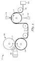
- FIG. 3 is a schematic diagram of an exemplary apparatus suitable for making the microperforated polymeric films of the present disclosure
- FIGS. 4 a and 4 b are top view pictures of representative portions of a microperforated polymeric film according to Comparative Example A;
- FIG. 5 is a top view picture of a representative portion of the second surface of a microperforated polymeric film according to Example 1;
- FIG. 6 is a cross-sectional picture of a representative portion of an embossed polymeric film according to Example 2.
- FIG. 7 is a magnified top view picture of a portion of the second surface of a microperforated polymeric film according to Example 2.
- FIG. 8 a is a further magnified top view picture of a representative portion of the first surface of a microperforated polymeric film according to Example 2;
- FIG. 8 b is a further magnified top view picture of a representative portion of the second surface of a microperforated polymeric film according to Example 2.
- FIG. 8 c is a cross-sectional picture of a microperforated polymeric film according to Example 2.
- a and/or B includes, (A and B) and (A or B).
- At least two includes all numbers of two and greater (e.g., at least 4, at least 6, at least 8, at least 10, at least 25, at least 50, at least 100, etc.).
- At least one includes all numbers of one and greater (e.g., at least 2, at least 4, at least 6, at least 8, at least 10, at least 25, at least 50, at least 100, etc.).
- the present description provides embodiments of a microperforated polymeric film and methods for perforating polymeric films using thermal treatments wherein the microperforated polymeric film is thick and comprises a high density of perforations and a high percent open area.
- the thick polymer film provides strength to the resulting article, while the high percent open area enables these microperforated polymeric films to be used in high throughput applications such as particulate filtering or acoustics.
- Microperforated films according to the present disclosure may be formed from various materials such as, for instance, polymeric materials. While many types of polymeric materials may be used, a particularly advantageous method of manufacturing a microperforated film utilizes thermoplastic materials.
- FIG. 1 a depicts a cross-sectional view of one embodiment of a microperforated film of the present disclosure.
- Microperforated polymeric film 10 comprises channels 20 A, 20 B, and 20 C (collectively plurality of channels 20 ) perpendicular to a first surface and an opposing second surface. As shown in FIG. 1 a , microperforated polymeric film 10 comprises first surface 14 and second surface 16 .
- Each channel (e.g., 22 A) of the plurality of channels comprises a first opening (e.g., 12 A), which intersects first surface 14 and a second opening (e.g., 22 A), which intersects second surface 16 , creating a through opening.
- FIG. 1 b depicts a top view of second surface 16 , showing second openings 22 A, 22 B, 22 C . . . 22 n (collectively plurality of openings 22 ).
- the shape and dimensions of the openings are not particularly limited.
- the openings of the channels may be elliptical, round, circular, oval, triangular, square, hexagonal, octagonal, etc.
- the opening of a channel intersecting the first surface e.g., first opening 12 A
- the term diameter is used herein to refer to the diameter of a circle having the equivalent area as the non-circular cross-section.
- the diameter of the first opening may be at least 100, 200, or even 500 micrometers; at most 100, 200, 500, or even 2000 micrometers.
- the diameter of the second opening may be at least 50, 100, 200, or even 500 micrometers; at most 100, 200, 500, or even 1000 micrometers. Due to the processing, the diameter of the first opening (e.g., 12 A) may be larger than the diameter of the second opening (e.g., 22 A) on the second surface (i.e., the thermal treated surface).
- the shape and dimensions of the channels are also not particularly limited and may be influenced by the tooling and processing conditions (e.g., film tension and thermal treatment exposure).
- the plurality of channels is substantially perpendicular to the first and second surfaces (i.e., the channel is at most 2, 5, 10, 15, or even 20 degrees off axis due to processing of the film).
- Each channel in the plurality of channels may comprise any shape, including, for example, cylindrical or a geometric prism (e.g., a hexagonal prism, a square prism, etc.).
- the shape of the channel may be slightly distorted due to the thermal treatment process.
- the channels are tapered.
- the microperforated polymeric film comprises at least 1000, 2000, 4000, 5000, 6000, 7000, 8000, 10000, or even 25000 channels per square inch.
- the plurality of channels in the microperforated polymeric film may be ordered or random.
- a square array may be used; alternatively, a staggered array (for example, a hexagonal array) may be used, in order to increase the density of the perforations.
- the opening size, shape, and/or spacing may also vary over the microperforated polymeric film if desired.
- microperforated polymeric films of the present disclosure comprise at least 8, 10, 15, 20, 22, 25, 30, 35, 40, 50, or even 60% open area.
- Open area as used herein is in reference to the second surface and is defined as the sum total of the area occupied by the second openings for a given area of the second surface.
- the microperforated polymeric film comprises a film thickness of 75 to 500 micrometers.
- the film thickness is measured as the maximum distance between the first surface and the second surface on the microperforated polymeric film.
- film thickness 40 a is the distance between the first surface and the second surface of microperforated polymeric film 10 .
- this distance will be referred to as “the first certain distance” and is the maximum distance between the first surface and second surface of the microperforated polymeric film.
- the first certain distance is at least 50, 60, 70, 75, 80, or even 100 micrometers; at most 100, 150, 200, 300, 400, 500, 750, or even 800 micrometers.
- the second openings on the second surface are spaced apart by a certain distance, represented as distance 50 a in FIG. 1 b of at least 20, 25, 30, 40, 50, 60, 75, or even 100 micrometers; at most 75, 80, 90, 100, 125, 150, 175, 200, 300, 400, or even 500 micrometers.
- this distance will be referred to as “the second certain distance” and is the minimum distance between adjacent openings on the second surface.
- the ratio of the first certain distance to the second certain distance is greater than 0.25, 0.5, 1, 2, 3, or even 3.5.
- the microperforated polymeric films of the present disclosure are made from embossed polymeric films (i.e., polymeric films comprising cavities), which are exposed to thermal treatment processes to perforated the polymeric films.
- embossed polymeric film 200 comprises cavities 220 A, 220 B, and 220 C (collectively plurality of cavities 220 ). Each cavity comprises a cavity surface (e.g., 210 , 211 , and 212 ). The cavities are perpendicular to a first surface 240 and an opposing second surface 260 . As shown in FIG.
- skins 280 A, 280 B, and 280 C refer to the small membrane of polymeric material (i.e., skin) located between the bottom (or apex) of each cavity and second surface 260 .
- skins, or a portion thereof melt and retract and/or combusts, resulting in through openings or channels (e.g., channel 20 A as depicted in microperforated polymeric film 10 in FIG. 1 a ).
- FIGS. 1 a , 1 b , and 2 are not drawn to scale and are for illustrative purposes only.
- the embossed polymeric film is wrapped (skin-side facing out) around a support surface while the outside of the film is exposed to a thermal treatment.
- the thermal treatment heats the outermost layers of polymer leading to the displacement of the skins.
- the support surface is typically a smooth chill roller, which is used to keep the polymeric film cool when exposed to the thermal treatment to precisely control the temperature of the polymeric film.
- the chill roll does not provide adequate cooling of the polymeric film during the thermal treatment process.
- Applicants have found that the addition of a fluid between the embossed polymeric film and the support surface (e.g., chill roll) results in microperforated polymeric films with well controlled perforations.
- the temperature of the polymeric film cannot be controlled well enough during the thermal treatment to balance the melting of the skins while keeping enough of the polymeric film cool to maintain its strength and dimensional integrity. Because of the patterning of the embossed polymeric film (e.g., larger diameter openings spaced close together), in some embodiments less than 30, 25, 20, 10, or even 5% of the polymeric material is in direct contact with the support surface (e.g., the chill roll). The fluid is thought to act as a heat transfer agent, helping to keep all but the outermost layers of the polymeric film sufficiently cool such that when the embossed polymeric film is exposed to the thermal treatment step, there is not uncontrolled melt.
- the support surface e.g., the chill roll
- the first surface of the embossed polymeric film can be substantially coated with fluid, while entrapping a layer of gas (e.g., air) between the fluid and the apex of each cavity.
- gas e.g., air
- the gaseous layer is believed to insulate the skins from the cool under-layers, allowing the controlled melting of the skins.
- Described below is the process of forming a microperforated polymeric film according to the present disclosure.
- the process for fabricating a microperforated polymeric film includes, forming the polymeric material, contacting the formed polymeric material with a tooling, hardening the polymeric material on the tooling, removing the embossed polymeric material from the tooling, and then displacing the skins
- Forming a polymeric material may include selecting the type of polymer and additives, if any.
- the polymeric material comprises a polyolefin, such as for example, polyethylene or polypropylene, and combinations thereof.
- Copolymers a polymer comprising at least two different interpolymerized monomers and include: terpolymers (comprising three different monomers), tetrapolymers (comprising four different monomers), etc.) and blends may also be used.
- An exemplary copolymer is a propylene ethylene copolymer.
- the type and amount of additives can vary and are typically selected in consideration of the desired properties of the microperforated polymeric film (for example, sound absorbance or filtering) as well as other characteristics of the film, such as for example, color, printability, adherability, smoke generation resistance, and heat/flame retardancy.
- a color code may be developed (i.e., a particular color corresponds to a particular perforation size) and colorants may be added to the polymeric film during the manufacturing process to indicate a particular perforation size.
- Additives may also be added to a polymeric material to increase its bending stiffness and/or surface density.
- the type of polymer as well as the specific physical characteristics (e.g., thickness, bending stiffness, surface density, opening diameter, opening spacing, and/or opening shape) of the film can vary.
- the polymeric film has a substantially uniform thickness over the entire film. That is, the film has a uniform thickness with the exception of possible variations in the vicinity of the microperforations, which may result from the process of forming the microperforations and/or displacing of thin skins, and natural variations in the manufacturing processes discussed below.
- the polymeric material may be contacted with a tool having features that are shaped and arranged to form cavities in the polymeric material, for example a tooling comprising projections.
- the cavities formed in the polymeric material will provide the desired properties (for example, filtering, and sound absorption) of the microperforated polymeric film.
- the polymeric material may be contacted with the tooling using a number of different techniques such as, for example, embossing, including extrusion embossing or compression molding.
- the polymeric material may be in the form of a molten extrudate, which is brought in contact with the tooling, or in the form of a pre-formed film, which is heated and placed into contact with the tooling.
- the polymeric material is first brought to an embossable state by heating the polymeric material above its softening point, melting point, or polymeric glass transition temperature. The polymeric material is then brought in contact with the tooling to which the polymeric material generally conforms.
- the tooling typically includes a base surface from which the features (e.g., projections) extend.
- the shape and surface of the projection is not particularly limited, however, the following may be considered when designing the projections.
- the projection shape may be limited by the ease of machining.
- the projection shape may be designed to facilitate the removal of the embossed polymeric film. For example, an appropriate draft angle greater than at least 0.5 degrees may be designed into the projection to ensure proper removal of the resulting embossed polymeric film from the tooling. This is particularly important when the design involves a projection having nearly straight walls.
- the projections may be designed to provide a resulting microperforated polymeric film that is effective for its intended use (e.g., particulate filtering, acoustics, etc.).
- the projections may be machined using techniques known in the art, for example, milling, cutting, grinding, chemically etching, electrode discharge machining, electrochemical etching, laser ablation, focused ion beam machining, or combinations thereof.
- the tooling is a negative mold for the embossed polymeric film
- the shape, dimensions, and arrangement of the features on the tool are suitably selected in consideration of the desired properties of the cavities to be formed in the embossed polymeric material and the subsequent channels of the microperforated polymeric film.
- projections on the tooling have a height corresponding to the desired film thickness and have edges that taper from a widest diameter to a narrowest diameter to provide tapered cavities.
- the polymeric material After contacting the flowable polymeric material with the tooling, the polymeric material is solidified to form a solidified polymeric film having features corresponding to the tool.
- the polymeric material typically solidifies while in contact with the tool. After solidifying, the solidified polymeric film is then removed from the tool.
- the resulting embossed film comprises a plurality of cavities.
- the cavities may not be identical positive replications of the tooling projections.
- the cavities and distance between cavities may be slightly stretched. If the projections are close together and depending on the line speeds and melt temperatures, the polymeric film may not completely form to the tooling, causing the valleys between the projections to not be completely filled with polymeric material. This may result in a non planar first surface of the microperforated polymeric film, such as that disclosed in FIG. 6 .
- a skin may be left covering or partially obstructing the bottom (or apex) of each cavity.
- the solidified polymeric film typically undergoes thermal treatment to displace the skins. Because the plurality of cavities typically turn into the plurality of channels (or through openings) after thermal treatment process, the cavity size, shape, and spacing is generally similar to that described for the channels above.
- a thermal treatment process is used to displace the skins to form the microperforated polymeric film
- Skin displacement may be performed using a number of different thermal treatments including, for example, forced air treatment, hot air treatment, flame treatment, radiant heat treatment (such as infrared), corona treatment, plasma treatment, ultrasonic, laser, or combinations thereof.
- the thermal treatment is used to heat the first few polymer layers to temperatures at which the polymer readily flows.
- the molten polymer of the skin ruptures and retracts, thereby defining a through opening, or channel, in the polymeric film.
- Thermal treatment generally works well for polymer films that are thicker (e.g., greater than about 300 micrometers) and have a lower percent opening per unit area (e.g., less than 3%).
- the present disclosure provides a method of controlling the temperature of the polymeric film during the thermal treatment process to produce microperforated polymeric films with a large percentage open area and high density of openings.
- a fluid is provided between the polymeric film and the support surface.
- the fluid serves as an intimately-contacting heat sink and heat transfer pathway between the embossed polymeric film and the support surface.
- the polymeric material in contact with the fluid remains below its softening temperature even as the skin layer is exposed to the heat source, thus maintaining strength and dimensional integrity of the polymeric film.
- An additional advantage is the potential vaporization of the fluid, which can cause a pressure increase within the cavities of the embossed polymeric film, assisting in perforating the film.
- Fluids of the present disclosure include those that are non-flammable.
- Exemplary fluid include, water, and fluorinated solvents.
- a syringe pump and needle die may be used to apply the fluid although other methods of applying fluid may also be employed.
- the fluid may be applied directly to the embossed polymeric film or to the support surface, which supports and generally cools the polymeric film during the thermal treatment process.
- the support surface is smooth (i.e., no noticeable surface pattern).
- a textured pattern may be etched or engraved into the support surface. See for example, the method disclosed in U.S. application Ser. No. 12/362,048 (Ehnes, et al.).
- the capillary forces of the fine grooves on the support surface may hold the fluid in a thin film of uniform thickness, preventing the beading of the fluid, which may result in inconsistently displaced skins across the microperforated polymeric film.
- Texture of the support surface means that any two dimensions (length, width, and/or depth) of the texture are less than or equal to 100, 75, 50, 20 or even 10 micrometers in length. In one embodiment, less than 30% or even 20% of the surface of the textured support surface is flat (i.e., not textured).
- the support surface may be covered with, for example, a high surface energy coating or finish to enable better wetting of the fluid.
- an additional flat film may be introduced between the support surface and the embossed polymeric film prior to thermal treatment.
- the fluid may be applied to the top surface of the secondary film prior to contacting with the embossed polymeric film.
- a fluid saturated fibrous web may be introduced between the support surface and the embossed polymeric film prior to thermal treatment.
- the fibrous web could be paper based, nonwoven or woven fabric in nature. Additional coating methods may be used to coat fluid onto the back side of the film or surface of the chill roll. Methods include roll coating, curtain coating, contact die, spray coating, enclosed doctor blade or sponge type transfer coating methods.
- the melting and displacement of the skins can be controlled. For example, if small droplets of fluid are sprayed onto the first surface of the embossed polymeric film, the skins may not be displaced during the thermal treatment. If the cavities in the embossed polymeric film are completely filled with the fluid, which can act as a heat sink, the skins may not get warm enough during the thermal treatment and thus, the cavities or a portion of the cavities will not open into a channel.
- the thermal energy is typically applied from the side of the film bearing the skin while a metal surface (e.g., a roll) acting as a heat sink, may be provided against the opposite surface, to draw heat from the bulk portions so that the bulk portions of the film do not deform during the thermal displacement treatment.
- a metal surface e.g., a roll
- the film may also be maintained under tension during and/or after the thermal energy treatment to assist in opening the openings. This may be done, for example, by applying positive pressure or vacuum to one side of the film.
- a variety of burners for thermal displacement treatment are commercially available, for example, from Flynn Burner Corporation, New Rochelle, N.Y.; Aerogen Company, Ltd., Alton, United Kingdom, and Sherman Treaters Ltd., Thame, United Kingdom.
- One preferred burner is commercially available from Flynn Burner Corporation as Series 850, which has an eight-port, 32 inch (81.3 cm) actual length that was deckled to 27 inch (68.6 cm) in length, stainless steel, deckled ribbon mounted in a cast iron housing.
- a ribbon burner is most preferred for the flame perforation of polymeric films, but other types of burners such as drilled-port or slot design burners may also be used.
- an oxidizer is mixed with the fuel before it feeds the flame used in the flame-perforating process of the disclosure.
- FIG. 3 illustrates a schematic diagram of an exemplary extrusion embossing system for forming microperforated polymeric film in accordance with one embodiment of the disclosure.
- the exemplary extrusion embossing system 120 generally includes an extrusion die 122 from which polymeric film 124 is extruded.
- the extrusion die 122 lies in fluid communication with nip roll system 126 , which includes a first roll 128 having a generally flat exterior surface (backup roll) and a second roll 130 having posts on its exterior surface (tooling roll).
- the polymeric film 124 generally flows between the first and second rolls 128 and 130 , conforms to the posts, and solidifies to form the embossed polymeric film 132 .
- a sacrificial polymeric film is provided between polymeric film 124 and first roll 128 to provide more uniform pressure against second roll 130 .
- the embossed polymeric film 132 moves out of the nip roll system 126 to a storage bin 134 for temporary storage.
- the storage bin 134 may, for example, be a winding roll upon which the embossed polymeric film is wound.
- the storage bin 134 may be a sheet bin which stores cut sheets of the embossed polymeric film 132 .
- the exemplary system 120 includes a displacement treatment system 136 for displacing skins covering the cavities on the embossed polymeric film to create the microperforated polymeric film 144 .
- the displacement treatment system 136 is provided in-line between nip roll system 126 and storage bin 134 .
- the displacement treatment system 136 may be an out-of-line system where stored embossed polymeric film from the storage bin 134 is moved to another assembly line having the displacement treatment system 136 . While a roll-based process provides significant cost savings, a step wise process using, for example, a sheet-like tool system, rather than a nip roll system, may alternatively be used.
- backing roll 138 is provided opposite the displacement treatment system.
- the support surface 140 of the backing roll 138 is temperature-controlled, relative to the ambient temperature around the exemplary system 120 .
- the support surface 140 of the backing roll 138 may be temperature-controlled by any means known in the art.
- the support surface 140 of the backing roll 138 may be cooled by providing cooled water through a hollow shaft in backing roll 138 .
- support surface 140 is smooth, (i.e., does not contain any features).
- support surface 140 includes a textured pattern on the support surface 140 .
- the textured pattern may be a plurality of fine grooves or indentations along the support surface 140 .
- other suitable means like ablation or drilling could be used to create an acceptable texture pattern.
- a fluid is provided between the embossed polymeric film 132 and support surface 140 .
- the manner in which the fluid may be applied to the support surface may be varied by one skilled in the art, depending on the pressure, rate or velocity of the fluid pumped through the fluid applicator 142 .
- the support surface is cooled to 20° C., 15° C., 10° C. or even 5° C.
- the apparatus may be modified to include an oxygen enriched flame as described in U.S. Publ. No. 2005/0073070 (Getschel et al.).
- microperforated polymeric films and processing techniques discussed above provide a number of advantages. As compared to conventional fibrous materials and perforated sheet materials, the above microperforated polymeric films are relatively inexpensive to form and are capable of wider use.
- the use of post molding provides a relatively inexpensive method of forming high aspect ratio openings.
- the use of post molding also provides significant quality advantages over other methods of generating perforations in films. For example, post molding generates significantly less debris or particulate matter than, for example, mechanical punching, drilling or boring techniques.
- the above process also allows for continuous processing and can provide significant cost savings over conventional processing methods. Further, using the methods as disclosed herein, may enable the fabrication of microperforated polymeric films having opening of various shapes and tightly controlled feature sizes.
- microperforated polymeric films of the present disclosure may be used in variety of applications, for example, filtering or acoustics.
- the microperforated polymeric films of the present disclosure may be used for filtering liquids or gases.
- a mixture comprising particulates may be contacted with a microperforated polymeric film as disclosed herein, and the microperforated polymeric film may be used to filter the mixture.
- the microperforated polymeric films according to the present disclosure may be used as filters in paint sprayers of the kind disclosed in W.O. Publ. No. 2006/055138 (Joseph et al.) and U.S. Publ. No. 2006/0049099 (Chang).
- the microperforated polymeric film according to the present disclosure comprises channels or openings, which may serve as passages through the filter. Objects in a sample larger than the openings are blocked from passage.
- Novel features of using the microperforated polymeric films of the present disclosure for particulate filtering include the ability to optimally shape the fluid passages and precisely controlled feature sizes. These features may result in a superior filter that minimizes pressure drop, while precisely limiting the size of particles that can pass through.
- circular-shaped openings are superior for minimizing pressure drop across a filter (assuming the same percent open area, thickness, etc.).
- the circular shape has minimum perimeter length and, hence, the opening has the least amount of surface-to-fluid contact area. This produces the least pressure drop since shear stresses in the fluid are proportionate to the contact area. Therefore, as with particle size control, it is preferable to make openings as circular as possible.
- a multilayered filter device comprises the microperforated polymeric film as disclosed herein and a second permeable material extending across at least a portion of the microperforated polymeric film.
- the second permeable material captures the largest objects. This prevents the larger objects from quickly plugging the first layer microreplicated polymeric film, thereby extending the life of the filter.
- This embodiment may be facilitated by one or more spacings between the layers. The spacing(s) may be created by a plurality of spacers, which are integral with at least one of the microperforated polymeric film or the second polymeric film. These spaces create a fluid flow gap between the adjacent layers.
- the second permeable material is a second microperforated polymeric film.
- the multi-layer construction comprises an outer layer of a non-woven-type material, and a microperforated polymeric films disclosed herein.
- the non-woven type material is effective at capturing large and gelatinous objects without substantially blocking fluid flow through the underlying filtering layers.
- Item 1 A method of forming a microperforated polymeric film comprising:
- a polymeric film comprising opposed first and second surfaces and a plurality of cavities there between, wherein the plurality of cavities is open to the first surface and includes a cavity surface wherein the cavity surface intersects the first surface;
- Item 2 The method of item 1 wherein a layer of gas separates the fluid from the apex of the cavity of at least some of the plurality of cavities.
- Item 3 The method of any one of the previous items, wherein the fluid is water.
- Item 4 The method of any one of the previous items, wherein the support surface is a chilled roller.
- Item 5 The method of any one of the previous items, wherein the thermal treatment is one of: flame, hot air, radiant heat, and combinations thereof.
- Item 6 The method of any one of the previous items, wherein the support surface comprises at least one of: a texture, a coating, and combinations thereof.
- Item 7 The article made by the method of any one of items 1 to 6, wherein the article is a particulate filter for liquids or gases.
- a microperforated polymeric film comprising: comprising: (i) opposed first and second surfaces separated by a first certain distance; and (ii) a plurality of channels perpendicular to the first and second surfaces, wherein a first opening of each channel intersects the first surface and a second opening of each channel intersects the second surface; wherein the diameter of the first opening is larger than the diameter of the second opening and the second openings on the second surface are spaced apart by a second certain distance; wherein the ratio of the first certain distance to the second certain distance is at least 0.25; and further wherein the second surface has an open area of at least 10%.
- Item 9 The microperforated polymeric film of item 8, wherein the distance between the opposed first and second surfaces is at least 75 micrometers.
- Item 11 The microperforated polymeric film according to any one items 8-10, wherein the channel has tapered walls.
- the second opening is elliptical or round in shape.
- Item 13 The microperforated polymeric film according to any one of items 8-12, wherein the second openings are less than 500 microns in diameter.
- Item 14 The microperforated polymeric film according to any one of items 8-13, further comprising at least one of embedded fibers, or integral ribs extending along at least one major surface.
- a microperforated polymeric film comprising: (i) opposed first and second surfaces; and (ii) a plurality of channels perpendicular to the first and second surfaces, wherein a first opening of each channel intersects the first surface and a second opening of each channel intersects the second surface; wherein the diameter of the first opening is larger than the diameter of the second opening; wherein the second surface has an open area of at least 20%; and further wherein the second surface comprises at least 6,000 openings per square inch.
- a multilayered filter device comprising:
- Item 18 The multilayered filter device of item 17, wherein the plurality of spacers is integral with at least one of the microperforated polymeric film or the second permeable material.
- a method of filtering particulates comprising:
- Item 20 The method of filtering particulates of item 19, wherein the mixture is a paint.
- cm centimeter
- ° F. Fahrenheit
- ° C. Centigrade
- rpm revolutions per minute
- m meter
- min minutes
- N Newtons
- lbf pound force
- ⁇ m micrometer
- hr hour
- s second
- mm millimeter
- mL milliliter.
- MFI melt flow index
- the molten polymer resin (i.e., extrudate) was fed into a vertical two roll nip comprising a tooling roll and backup roll.
- the 30.48 cm (12-inch) diameter tooling roll comprises hexagonally shaped posts configured in a frusto-hexagonal array pattern, with a positive sidewall angle of about 10 degrees.
- the height of the posts was approximately 250 ⁇ m, with a distal width (i.e., distance between opposing sides across the hexagonal post top) of 225 micrometers and a channel width (i.e., distance between the edge of one hexagonal post and its nearest neighbor on the top of the tool) of 150 micrometers.
- the 30.48 cm (12-inch) diameter backup roll comprised a 0.635 cm (0.25 inch) 80 durometer (Shore A) rubber covering, type “SS100” from American Roller Company, Waterbury, Conn.
- a sacrificial 75 micrometer (3 mil) polyester teraphthlate (PET) film was fed between the backup roll and the molten polymer resin, and was removed after embossing and solidifying of the polymeric film.
- the polymeric film was a positive of the tooling, comprising cavities where the posts of the tool were contacted. Because of the nip force between the tooling roll and the backup roll, a thin film (i.e., a skin) was left between the bottom of each cavity and the second surface of the embossed polymeric film.
- the chill roll temperature was controlled to 21° C. (70° F.).
- the embossed film was exposed to a propane fired, 8-port aluminum burner (30.48 cm (12 inch) Extruded Aluminum 861 Series Ribbon Burner, from Flynn Burner Corporation, New Rochelle, N.Y.). Burner-to-film gap was 20.3 mm, the energy output was 288.5 Watt hours/cm (2500 British Thermal Units/Hour/inch) at a line speed of 12.2 m/min (40 ft/min).
- Comparative Example A was prepared following the Flame Treatment Process above.
- the resulting polymeric film showed complete failure, i.e., uncontrolled melting and bubbling over substantially all areas of the polymeric film as shown in FIGS. 4 a and 4 b . It is believed that the embossed film was not sufficiently cooled by the chill-roll during the flame treatment, resulting in large-scale, uncontrolled melting of the film with no apparent channels (or through openings) in any substantial portion of the film.
- Example 1 was prepared as described in Comparative Example A except that deionized water was used between the chill roll and the embossed polymeric film during the flame treatment.
- the deionized water was applied to the first major surface of the embossed film approximately two feet up-web before the embossed film contacted the chill roll.
- the deionized water was applied by means of a syringe pump and a water spray die, as described in U.S. Pat. No. 5,115,972 (Maier et al.).
- the deionized water was sprayed using 19 nozzles over a 23 cm (9 inch) span, having a flow rate of 37 mL/min with an air pressure of 103,400 N/m 2 (15 psi).
- the resulting polymeric film was dimensionally well preserved, but exhibited variability in skin displacement. Many cavities were fully opened, creating clean through openings, but some cavities were only partially opened or not opened at all.
- a representative film is shown in FIG. 5 .
- Example 2 was prepared as described in Example 1 except for changes made to the chill roll surface and where the deionized water was applied.
- the smooth, water-cooled chill roll was substituted with a water-cooled chill roll having an engraved pattern comprised of pyramids, 62 micrometer pitch, 30 micrometers high, 10 degree bias angle on one side, and a 90 degree tip angle, as described in U.S. application Ser. No. 12/362,048 (Ehnes, et al.).
- the nozzles were positioned opposite from the flame as shown in FIG. 3 , applying the deionized water directly onto the chill roll before the chill roll contacted the embossed film.
- Shown in FIG. 6 is a cross sectional view of the embossed polymeric film.
- Surface 640 is the first surface of the polymeric film contacting the tooling. Because of the processing conditions, the polymeric film did not completely fill the tooling, resulting in a “waffle type” surface. In the figure, two full cavities ( 620 A and 620 B) and three polymer sections separating the cavities ( 630 A, 630 B, and 630 C) are observed. Careful inspection of FIG. 6 shows the thin skins ( 680 A and 680 B) at the bottom of cavities 620 A and 620 B, respectively.
- FIGS. 7 and 8 a - 8 c A representative film is shown in FIGS. 7 and 8 a - 8 c .
- FIG. 7 is a top view of the second surface of a portion of the microperforated polymeric film.
- FIG. 8 a is a further magnified top view of the first surface of the microperforated polymeric film. The channels are tapered with the larger diameter first openings being hexagonal in shape, while the smaller diameter second openings are oval in shape.
- FIG. 8 b is a further magnified top view of the second surface of microperforated polymeric film, only the second openings of the plurality of channels is observed. Also depicted on FIG.
- FIG. 8 b is 50 B, which is the minimum distance (second certain distance) between adjacent openings on the second surface.
- FIG. 8C is a cross-sectional view of the microperforated polymeric film. Surface 860 is the second surface of the polymeric film which was exposed to the thermal treatment. The skins have been displaced, resulting in channels (or through openings).
- FIG. 8 c two full channels ( 820 A and 820 B) and three polymer sections separating the cavities ( 830 A, 830 B, and 830 C) are observed. Comparing FIGS. 6 and 8C , one can note the differences in shape of the cavities versus the channels and the change in the polymer sections separating the cavities as a result of the thermal treatment.
- the distance between the first and second surface (i.e., the first certain distance, e.g., distance 40 B in FIG. 8 c ) of the microperforated polymeric film was measured to be 229 micrometers (9 mils) using a micrometer (Model 49-70-01-001 from Testing Machines, Inc., Ronkonkoma, N.Y.).
- the minimum distance (i.e., the second certain distance, e.g., distance 50 B in FIG. 8 b ) between two adjacent second openings on the second surface was measured to be 140 micrometers (5.5 mils) using a bench-top microscope (TM-1000, Hitachi High-Technologies America, Inc., Pleasanton, Calif.
- the ratio of the first certain distance to the second certain distance for Example 2 was calculated to be 1.63.
- the hole density was 982 holes/cm 2 (6336 holes per square inch) with an open area of 32%.
- Example 3 was prepared as described in Example 2, with the following exceptions: the polymer was a blend comprising 25% of the polypropylene homopolymer and 75% of a polyolefin elastomer (an ethylene-octene copolymer) available under the trade designation “ENGAGE 8401” obtained by Dow Plastics, Midland, Mich.; and the process conditions shown in Table 2 were used. The resulting microperforated polymeric film showed uniform openings.
- a polyolefin elastomer an ethylene-octene copolymer
Abstract
Description
wherein the second surface has an open area of at least 10%.
Item 9. The microperforated polymeric film of item 8, wherein the distance between the opposed first and second surfaces is at least 75 micrometers.
Item 11. The microperforated polymeric film according to any one items 8-10, wherein the channel has tapered walls.
Item 12. The microperforated polymeric film according to any one of items 8-11, wherein the second opening is elliptical or round in shape.
Item 13. The microperforated polymeric film according to any one of items 8-12, wherein the second openings are less than 500 microns in diameter.
Item 15. The microperforated polymeric film according to any one of items 8-14, wherein the second certain distance is at least 75 micrometers.
(i) opposed first and second surfaces; and (ii) a plurality of channels perpendicular to the first and second surfaces, wherein a first opening of each channel intersects the first surface and a second opening of each channel intersects the second surface; wherein the diameter of the first opening is larger than the diameter of the second opening; wherein the second surface has an open area of at least 20%; and further wherein the second surface comprises at least 6,000 openings per square inch.
Item 17. A multilayered filter device comprising:
| TABLE 1 | |||
| Extruder and Die Temperature | 204° C. (400° F.) | ||
| Setting | |||
| Extruder screw speed | 15 rpm | ||
| Tooling Roll Temperature | 21° C. (70° F.) | ||
| Backup Roll Temperature | 21° C. (70° F.) | ||
| Nip Force | 13,344 N (3000 Pound-Force) | ||
| Line Speed | 12.2 m/min (40 feet/min) | ||
Flame Treatment Process
| TABLE 2 | |||
| Extruder and Die Temperature | 190° C. (375° F.) | ||
| Setting | |||
| Extruder screw speed | 15 rpm | ||
| Tooling Roll Temperature | 21° C. (70° F.) | ||
| Backup Roll Temperature | 21° C. (70° F.) | ||
| Nip Force | 14679 N (3300 Pound-Force) | ||
| Line Speed | 11.6 m/min (38 feet/min) | ||
Claims (8)
Priority Applications (1)
| Application Number | Priority Date | Filing Date | Title |
|---|---|---|---|
| US13/514,336 US9238203B2 (en) | 2009-12-14 | 2010-12-14 | Microperforated polymeric film and methods of making and using the same |
Applications Claiming Priority (3)
| Application Number | Priority Date | Filing Date | Title |
|---|---|---|---|
| US28610209P | 2009-12-14 | 2009-12-14 | |
| PCT/US2010/060160 WO2011081894A1 (en) | 2009-12-14 | 2010-12-14 | Microperforated polymeric film and methods of making and using the same |
| US13/514,336 US9238203B2 (en) | 2009-12-14 | 2010-12-14 | Microperforated polymeric film and methods of making and using the same |
Related Parent Applications (1)
| Application Number | Title | Priority Date | Filing Date |
|---|---|---|---|
| PCT/US2010/060160 A-371-Of-International WO2011081894A1 (en) | 2009-12-14 | 2010-12-14 | Microperforated polymeric film and methods of making and using the same |
Related Child Applications (1)
| Application Number | Title | Priority Date | Filing Date |
|---|---|---|---|
| US14/923,492 Division US20160045846A1 (en) | 2009-12-14 | 2015-10-27 | Microperforated polymeric film and methods of making and using the same |
Publications (2)
| Publication Number | Publication Date |
|---|---|
| US20120244314A1 US20120244314A1 (en) | 2012-09-27 |
| US9238203B2 true US9238203B2 (en) | 2016-01-19 |
Family
ID=43501100
Family Applications (2)
| Application Number | Title | Priority Date | Filing Date |
|---|---|---|---|
| US13/514,336 Expired - Fee Related US9238203B2 (en) | 2009-12-14 | 2010-12-14 | Microperforated polymeric film and methods of making and using the same |
| US14/923,492 Abandoned US20160045846A1 (en) | 2009-12-14 | 2015-10-27 | Microperforated polymeric film and methods of making and using the same |
Family Applications After (1)
| Application Number | Title | Priority Date | Filing Date |
|---|---|---|---|
| US14/923,492 Abandoned US20160045846A1 (en) | 2009-12-14 | 2015-10-27 | Microperforated polymeric film and methods of making and using the same |
Country Status (7)
| Country | Link |
|---|---|
| US (2) | US9238203B2 (en) |
| EP (1) | EP2519339A1 (en) |
| JP (2) | JP5866294B2 (en) |
| KR (1) | KR101822209B1 (en) |
| RU (1) | RU2522441C2 (en) |
| TW (1) | TWI506070B (en) |
| WO (1) | WO2011081894A1 (en) |
Cited By (7)
| Publication number | Priority date | Publication date | Assignee | Title |
|---|---|---|---|---|
| US10704254B2 (en) | 2014-02-18 | 2020-07-07 | 3M Innovative Properties Company | Easy to apply air and water barrier articles |
| WO2020217131A1 (en) | 2019-04-25 | 2020-10-29 | 3M Innovative Properties Company | Acoustic articles and methods thereof |
| US10987837B2 (en) | 2015-09-23 | 2021-04-27 | Inteva Products, Llc | Method and apparatus for nonwoven trim panels |
| US11105089B2 (en) | 2015-08-18 | 2021-08-31 | 3M Innovative Properties Company | Self-sealing articles including elastic porous layer |
| WO2022084830A1 (en) | 2020-10-23 | 2022-04-28 | 3M Innovative Properties Company | Acoustic articles and assemblies |
| US11365328B2 (en) | 2017-02-23 | 2022-06-21 | 3M Innovative Properties Company | Air and water barrier article including inelastic porous layer |
| US11731394B2 (en) | 2014-12-22 | 2023-08-22 | 3M Innovative Properties Company | Air and water barrier articles |
Families Citing this family (28)
| Publication number | Priority date | Publication date | Assignee | Title |
|---|---|---|---|---|
| CN103582329B (en) * | 2012-07-24 | 2016-08-03 | 富泰华工业(深圳)有限公司 | Housing and manufacture method thereof |
| US10040018B2 (en) | 2013-01-09 | 2018-08-07 | Imagine Tf, Llc | Fluid filters and methods of use |
| JP6491184B2 (en) * | 2013-03-12 | 2019-03-27 | スリーエム イノベイティブ プロパティズ カンパニー | Polymer multilayer film and method for producing the same |
| CN105050806A (en) * | 2013-03-12 | 2015-11-11 | 3M创新有限公司 | Polymeric multilayer films and methods to make the same |
| KR20150127634A (en) * | 2013-03-12 | 2015-11-17 | 쓰리엠 이노베이티브 프로퍼티즈 캄파니 | Method of making polymeric multilayer films |
| US9168476B2 (en) | 2013-10-11 | 2015-10-27 | 3M Innovative Properties Company | Air filter comprising a microperforated film, and method of using |
| JP6807230B2 (en) * | 2013-12-12 | 2021-01-06 | スリーエム イノベイティブ プロパティズ カンパニー | Polymer multilayer film and its manufacturing method |
| JP6491211B2 (en) * | 2013-12-12 | 2019-03-27 | スリーエム イノベイティブ プロパティズ カンパニー | Method for producing polymer multilayer film |
| WO2015183354A2 (en) | 2014-02-18 | 2015-12-03 | 3M Innovative Properties Company | Self sealing articles |
| ES2698161T3 (en) * | 2014-04-08 | 2019-01-31 | Pantex Int S P A | Absorbent sanitary article comprising a multilayer material |
| US9861920B1 (en) | 2015-05-01 | 2018-01-09 | Imagine Tf, Llc | Three dimensional nanometer filters and methods of use |
| US10730047B2 (en) | 2014-06-24 | 2020-08-04 | Imagine Tf, Llc | Micro-channel fluid filters and methods of use |
| US10124275B2 (en) | 2014-09-05 | 2018-11-13 | Imagine Tf, Llc | Microstructure separation filters |
| WO2016133929A1 (en) | 2015-02-18 | 2016-08-25 | Imagine Tf, Llc | Three dimensional filter devices and apparatuses |
| AU2016233335B2 (en) * | 2015-03-17 | 2021-03-25 | President And Fellows Of Harvard College | Automated membrane fabrication system |
| US10118842B2 (en) | 2015-07-09 | 2018-11-06 | Imagine Tf, Llc | Deionizing fluid filter devices and methods of use |
| US10479046B2 (en) | 2015-08-19 | 2019-11-19 | Imagine Tf, Llc | Absorbent microstructure arrays and methods of use |
| ITUB20155364A1 (en) * | 2015-11-09 | 2017-05-09 | No El Srl | METHOD AND EQUIPMENT FOR THE DRILLING OF FILMS IN PLASTIC MATERIAL. |
| RU2627400C1 (en) * | 2016-02-24 | 2017-08-08 | Марк Юрьевич Коломиец | General purpose multi-layer material, forming flexible distribution channels system for selection, filtration, distribution and drainage of fluid media |
| CN110049956A (en) * | 2016-11-04 | 2019-07-23 | 康宁公司 | Microperforated panel system, application and the method for manufacturing microperforated panel system |
| WO2018231825A1 (en) * | 2017-06-12 | 2018-12-20 | Kci Licensing, Inc. | Foamed and textured sintered polymer wound filler |
| US10415601B2 (en) | 2017-07-07 | 2019-09-17 | Denso International America, Inc. | Blower noise suppressor |
| TWI651450B (en) * | 2017-08-17 | 2019-02-21 | 大中製線織造股份有限公司 | Thin film three-dimensional mesh cloth and manufacturing method thereof |
| FR3088848B1 (en) * | 2018-11-28 | 2020-12-04 | Airbus Operations Sas | A method of manufacturing an acoustic element of a sound absorption structure from at least one sheet of material |
| JP7292068B2 (en) * | 2019-03-15 | 2023-06-16 | 新科實業有限公司 | Thin film filter, thin film filter substrate, thin film filter manufacturing method, thin film filter substrate manufacturing method, MEMS microphone, and MEMS microphone manufacturing method |
| JP7284606B2 (en) | 2019-03-22 | 2023-05-31 | 新科實業有限公司 | MEMS package, MEMS microphone and method of manufacturing MEMS package |
| JP2021030100A (en) | 2019-08-15 | 2021-03-01 | 新科實業有限公司SAE Magnetics(H.K.)Ltd. | Thin film filter, thin film filter substrate, method of manufacturing thin film filter, method of manufacturing thin film filter substrate, mems microphone, and method of manufacturing mems microphone |
| CN114984764B (en) * | 2022-03-09 | 2023-02-03 | 嘉兴中芯纳米材料有限责任公司 | Nanofiber-based oil-water separation and purification material with shifted inclined hole structure and preparation method thereof |
Citations (26)
| Publication number | Priority date | Publication date | Assignee | Title |
|---|---|---|---|---|
| GB851473A (en) | 1956-01-03 | 1960-10-19 | Kendall & Co | Treatment of flexible, thermoplastic, organic polymeric sheets and films |
| GB1073605A (en) | 1962-12-21 | 1967-06-28 | Smith & Nephew | Improvements in and relating to perforating films of thermoplastic material |
| US3560601A (en) | 1968-11-25 | 1971-02-02 | Ford Motor Co | Process for manufacturing porous thermoplastic sheet material |
| US4248822A (en) | 1978-02-15 | 1981-02-03 | Lever Brothers Company | Process and apparatus for producing a moisture-permeable film |
| US4252516A (en) | 1979-08-23 | 1981-02-24 | Ethyl Corporation | Apparatus for producing perforated film |
| US4919810A (en) | 1986-05-30 | 1990-04-24 | Mitsubishi Rayon Co., Ltd. | Porous membrane |
| US5115972A (en) | 1991-02-06 | 1992-05-26 | Minnesota Mining And Manufacturing Company | Spray die for producing spray fans |
| RU2050930C1 (en) | 1992-08-04 | 1995-12-27 | Михаил Ярославович Алферов | Method for making sleeve-type filtering element |
| US5733628A (en) | 1996-10-10 | 1998-03-31 | Tredegar Industries, Inc. | Breathable elastic polymeric film laminates |
| US5948255A (en) | 1994-03-07 | 1999-09-07 | The Regents Of The University Of California | Microfabricated particle thin film filter and method of making it |
| WO2001019528A1 (en) | 1999-09-15 | 2001-03-22 | Aradigm Corporation | Pore structures for reduced pressure aerosolization |
| US20010050197A1 (en) * | 1998-07-24 | 2001-12-13 | Kenneth Brian Wood | Microperforated polymeric film for sound absorption and sound absorber using same |
| WO2002020668A2 (en) | 2000-09-05 | 2002-03-14 | Donaldson Company, Inc. | Polymer compositions, polymer microfibers, polymer nanofibers and applications including filter structure |
| US6599612B1 (en) | 1997-12-15 | 2003-07-29 | The Procter & Gamble Company | Process of forming a perforated web |
| US6598701B1 (en) | 2000-06-30 | 2003-07-29 | 3M Innovative Properties Company | Shaped microperforated polymeric film sound absorbers and methods of manufacturing the same |
| US6660361B1 (en) | 1997-12-22 | 2003-12-09 | Charles James Shimalla | Apertured web and an apparatus and process for supporting a starting web during formation of the apertured web |
| US20050073070A1 (en) | 2003-10-06 | 2005-04-07 | 3M Innovative Properties Company | Methods and apparatus for oxygen enriched flame-perforation of a polymer film |
| US20050104245A1 (en) | 1998-07-24 | 2005-05-19 | 3M.Innovative Properties Company | Process of forming a microperforated polymeric film for sound absorption |
| US20060049099A1 (en) | 2004-09-03 | 2006-03-09 | Chang Jen C | Filter device used in a paint cup of a spraying gun |
| US7037100B2 (en) | 2002-10-09 | 2006-05-02 | 3M Innovative Properties Company | Apparatus for flame-perforating films and methods of flame-perforating films |
| WO2006055138A1 (en) | 2004-11-18 | 2006-05-26 | 3M Innovative Properties Company | Liquid supply and filter assembly for a spray gun |
| WO2006058384A1 (en) | 2004-12-03 | 2006-06-08 | Siemens Water Technologies Corp. | Membrane post treatment |
| WO2007127891A2 (en) | 2006-04-27 | 2007-11-08 | 3M Innovative Properties Company | Methods of making structured films |
| WO2007127890A2 (en) | 2006-04-27 | 2007-11-08 | 3M Innovative Properties Company | Structured films having acoustical absorbance properties |
| RU2327510C1 (en) | 2006-10-09 | 2008-06-27 | Общество с ограниченной ответственностью "РЕАТРЕК-Фильтр" | Asymmetrical track-etched membrane and process of its production |
| WO2010088010A2 (en) | 2009-01-29 | 2010-08-05 | 3M Innovative Properties Company | Method for making an optical film having a variable prismatic structured surface |
Family Cites Families (15)
| Publication number | Priority date | Publication date | Assignee | Title |
|---|---|---|---|---|
| US851473A (en) | 1906-08-31 | 1907-04-23 | John W Yochem | Dashboard-holder. |
| US1073605A (en) | 1913-06-03 | 1913-09-23 | Gustaf Henrik Hultman | Method of removing impurities from coal-gas. |
| JPS5315104B2 (en) * | 1971-10-13 | 1978-05-22 | ||
| JPS5635223Y2 (en) * | 1974-07-27 | 1981-08-19 | ||
| US4272473A (en) * | 1978-12-07 | 1981-06-09 | The Procter & Gamble Company | Method for embossing and perforating a running ribbon of thermoplastic film on a metallic pattern roll |
| US4395215A (en) * | 1981-02-02 | 1983-07-26 | The Procter & Gamble Company | Film forming structure for uniformly debossing and selectively aperturing a resilient plastic web and method for its construction |
| US4609518A (en) * | 1985-05-31 | 1986-09-02 | The Procter & Gamble Company | Multi-phase process for debossing and perforating a polymeric web to coincide with the image of one or more three-dimensional forming structures |
| JPH05152020A (en) * | 1991-11-28 | 1993-06-18 | Nitto Denko Corp | Anisotropic conduction connector |
| RU94019986A (en) * | 1991-12-09 | 1996-04-27 | Миннесота Майнинг энд Мануфактуринг Компани (US) | Microstructural membrane and method for its manufacture |
| ATE270535T1 (en) * | 1997-12-15 | 2004-07-15 | Procter & Gamble | PROCESS FOR FILM PERFORATION |
| EP1140332A1 (en) * | 1998-12-23 | 2001-10-10 | Morphometrix Technologies Inc. | In-situ manufacture of membrane microfilters |
| CN101362058B (en) * | 1999-12-08 | 2011-10-12 | 巴克斯特国际公司 | Microporous filter membrane, method of making microporous filter membrane and separator employing microporous filter membranes |
| CN100503717C (en) * | 2000-09-05 | 2009-06-24 | 唐纳森公司 | Polymer, polymer microfiber, polymer nanofiber and applications including filter structures |
| JP2003088733A (en) * | 2001-09-20 | 2003-03-25 | Canon Inc | Gas/liquid separation membrane and its production method |
| JP2011031219A (en) * | 2009-08-05 | 2011-02-17 | Asahi Kasei Corp | Separation membrane with nano-holes and method for manufacturing the same |
-
2010
- 2010-12-13 TW TW099143566A patent/TWI506070B/en not_active IP Right Cessation
- 2010-12-14 RU RU2012121455/04A patent/RU2522441C2/en not_active IP Right Cessation
- 2010-12-14 EP EP10795550A patent/EP2519339A1/en not_active Withdrawn
- 2010-12-14 WO PCT/US2010/060160 patent/WO2011081894A1/en active Application Filing
- 2010-12-14 US US13/514,336 patent/US9238203B2/en not_active Expired - Fee Related
- 2010-12-14 KR KR1020127017735A patent/KR101822209B1/en active IP Right Grant
- 2010-12-14 JP JP2012543338A patent/JP5866294B2/en not_active Expired - Fee Related
-
2015
- 2015-05-27 JP JP2015107161A patent/JP6397798B2/en not_active Expired - Fee Related
- 2015-10-27 US US14/923,492 patent/US20160045846A1/en not_active Abandoned
Patent Citations (29)
| Publication number | Priority date | Publication date | Assignee | Title |
|---|---|---|---|---|
| GB851473A (en) | 1956-01-03 | 1960-10-19 | Kendall & Co | Treatment of flexible, thermoplastic, organic polymeric sheets and films |
| GB1073605A (en) | 1962-12-21 | 1967-06-28 | Smith & Nephew | Improvements in and relating to perforating films of thermoplastic material |
| US3560601A (en) | 1968-11-25 | 1971-02-02 | Ford Motor Co | Process for manufacturing porous thermoplastic sheet material |
| US4248822A (en) | 1978-02-15 | 1981-02-03 | Lever Brothers Company | Process and apparatus for producing a moisture-permeable film |
| US4252516A (en) | 1979-08-23 | 1981-02-24 | Ethyl Corporation | Apparatus for producing perforated film |
| US4919810A (en) | 1986-05-30 | 1990-04-24 | Mitsubishi Rayon Co., Ltd. | Porous membrane |
| US5115972A (en) | 1991-02-06 | 1992-05-26 | Minnesota Mining And Manufacturing Company | Spray die for producing spray fans |
| RU2050930C1 (en) | 1992-08-04 | 1995-12-27 | Михаил Ярославович Алферов | Method for making sleeve-type filtering element |
| US5948255A (en) | 1994-03-07 | 1999-09-07 | The Regents Of The University Of California | Microfabricated particle thin film filter and method of making it |
| US5733628A (en) | 1996-10-10 | 1998-03-31 | Tredegar Industries, Inc. | Breathable elastic polymeric film laminates |
| US6599612B1 (en) | 1997-12-15 | 2003-07-29 | The Procter & Gamble Company | Process of forming a perforated web |
| US6660361B1 (en) | 1997-12-22 | 2003-12-09 | Charles James Shimalla | Apertured web and an apparatus and process for supporting a starting web during formation of the apertured web |
| US20010050197A1 (en) * | 1998-07-24 | 2001-12-13 | Kenneth Brian Wood | Microperforated polymeric film for sound absorption and sound absorber using same |
| US20050104245A1 (en) | 1998-07-24 | 2005-05-19 | 3M.Innovative Properties Company | Process of forming a microperforated polymeric film for sound absorption |
| US6617002B2 (en) | 1998-07-24 | 2003-09-09 | Minnesota Mining And Manufacturing Company | Microperforated polymeric film for sound absorption and sound absorber using same |
| WO2001019528A1 (en) | 1999-09-15 | 2001-03-22 | Aradigm Corporation | Pore structures for reduced pressure aerosolization |
| US6598701B1 (en) | 2000-06-30 | 2003-07-29 | 3M Innovative Properties Company | Shaped microperforated polymeric film sound absorbers and methods of manufacturing the same |
| WO2002020668A2 (en) | 2000-09-05 | 2002-03-14 | Donaldson Company, Inc. | Polymer compositions, polymer microfibers, polymer nanofibers and applications including filter structure |
| US7037100B2 (en) | 2002-10-09 | 2006-05-02 | 3M Innovative Properties Company | Apparatus for flame-perforating films and methods of flame-perforating films |
| US20060125139A1 (en) | 2002-10-09 | 2006-06-15 | 3M Innovative Properties Company | Methods for flame-perforating films |
| US20060127639A1 (en) | 2002-10-09 | 2006-06-15 | Strobel Mark A | Flame-perforated films |
| US20050073070A1 (en) | 2003-10-06 | 2005-04-07 | 3M Innovative Properties Company | Methods and apparatus for oxygen enriched flame-perforation of a polymer film |
| US20060049099A1 (en) | 2004-09-03 | 2006-03-09 | Chang Jen C | Filter device used in a paint cup of a spraying gun |
| WO2006055138A1 (en) | 2004-11-18 | 2006-05-26 | 3M Innovative Properties Company | Liquid supply and filter assembly for a spray gun |
| WO2006058384A1 (en) | 2004-12-03 | 2006-06-08 | Siemens Water Technologies Corp. | Membrane post treatment |
| WO2007127891A2 (en) | 2006-04-27 | 2007-11-08 | 3M Innovative Properties Company | Methods of making structured films |
| WO2007127890A2 (en) | 2006-04-27 | 2007-11-08 | 3M Innovative Properties Company | Structured films having acoustical absorbance properties |
| RU2327510C1 (en) | 2006-10-09 | 2008-06-27 | Общество с ограниченной ответственностью "РЕАТРЕК-Фильтр" | Asymmetrical track-etched membrane and process of its production |
| WO2010088010A2 (en) | 2009-01-29 | 2010-08-05 | 3M Innovative Properties Company | Method for making an optical film having a variable prismatic structured surface |
Non-Patent Citations (1)
| Title |
|---|
| PCT International Search Report, PCT/US2010/060160, dated May 24, 2011, 6 pages. |
Cited By (8)
| Publication number | Priority date | Publication date | Assignee | Title |
|---|---|---|---|---|
| US10704254B2 (en) | 2014-02-18 | 2020-07-07 | 3M Innovative Properties Company | Easy to apply air and water barrier articles |
| US11731394B2 (en) | 2014-12-22 | 2023-08-22 | 3M Innovative Properties Company | Air and water barrier articles |
| US11105089B2 (en) | 2015-08-18 | 2021-08-31 | 3M Innovative Properties Company | Self-sealing articles including elastic porous layer |
| US11512463B2 (en) | 2015-08-18 | 2022-11-29 | 3M Innovative Properties Company | Air and water barrier article with porous layer and liner |
| US10987837B2 (en) | 2015-09-23 | 2021-04-27 | Inteva Products, Llc | Method and apparatus for nonwoven trim panels |
| US11365328B2 (en) | 2017-02-23 | 2022-06-21 | 3M Innovative Properties Company | Air and water barrier article including inelastic porous layer |
| WO2020217131A1 (en) | 2019-04-25 | 2020-10-29 | 3M Innovative Properties Company | Acoustic articles and methods thereof |
| WO2022084830A1 (en) | 2020-10-23 | 2022-04-28 | 3M Innovative Properties Company | Acoustic articles and assemblies |
Also Published As
| Publication number | Publication date |
|---|---|
| JP2013513472A (en) | 2013-04-22 |
| RU2012121455A (en) | 2014-01-27 |
| US20160045846A1 (en) | 2016-02-18 |
| US20120244314A1 (en) | 2012-09-27 |
| JP2015199069A (en) | 2015-11-12 |
| TWI506070B (en) | 2015-11-01 |
| JP5866294B2 (en) | 2016-02-17 |
| RU2522441C2 (en) | 2014-07-10 |
| JP6397798B2 (en) | 2018-09-26 |
| KR101822209B1 (en) | 2018-01-25 |
| AU2010337163A1 (en) | 2012-06-21 |
| EP2519339A1 (en) | 2012-11-07 |
| KR20120104299A (en) | 2012-09-20 |
| WO2011081894A1 (en) | 2011-07-07 |
| TW201129619A (en) | 2011-09-01 |
Similar Documents
| Publication | Publication Date | Title |
|---|---|---|
| US9238203B2 (en) | Microperforated polymeric film and methods of making and using the same | |
| US7037457B2 (en) | Systems and methods for composite webs with structured discrete polymeric regions | |
| US20160023393A1 (en) | Method of making polymeric multilayer films | |
| EP2969419B1 (en) | Polymeric multilayer film and methods to make the same | |
| CN1753774A (en) | Improved soft film | |
| EP3079867B1 (en) | Method of making polymeric multilayer films | |
| MXPA02006718A (en) | Antibacterial microporous film and method of making. | |
| CA2594263A1 (en) | Laminate of thermoplastic film materials exhibiting throughgoing porosity | |
| AU2013273670B2 (en) | Microperforated polymeric film and methods of making and using the same | |
| EP2969535B1 (en) | Polymeric multilayer films and methods to make the same | |
| JP2017503682A (en) | Polymer multilayer film and method for producing the same | |
| CA2957072C (en) | Ribbed and apertured fluoroplastic support sheet for a filter substrate and method of making same | |
| JP6866123B2 (en) | Porous film manufacturing method and porous film | |
| KR102170603B1 (en) | Separator element |
Legal Events
| Date | Code | Title | Description |
|---|---|---|---|
| AS | Assignment |
Owner name: 3M INNOVATIVE PROPERTIES COMPANY, MINNESOTA Free format text: ASSIGNMENT OF ASSIGNORS INTEREST;ASSIGNORS:SCHEIBNER, JOHN B.;HANSEN, BRENT R.;JOHNSON, TODD W.;AND OTHERS;SIGNING DATES FROM 20120510 TO 20120606;REEL/FRAME:028333/0619 |
|
| ZAAA | Notice of allowance and fees due |
Free format text: ORIGINAL CODE: NOA |
|
| ZAAB | Notice of allowance mailed |
Free format text: ORIGINAL CODE: MN/=. |
|
| STCF | Information on status: patent grant |
Free format text: PATENTED CASE |
|
| MAFP | Maintenance fee payment |
Free format text: PAYMENT OF MAINTENANCE FEE, 4TH YEAR, LARGE ENTITY (ORIGINAL EVENT CODE: M1551); ENTITY STATUS OF PATENT OWNER: LARGE ENTITY Year of fee payment: 4 |
|
| FEPP | Fee payment procedure |
Free format text: MAINTENANCE FEE REMINDER MAILED (ORIGINAL EVENT CODE: REM.); ENTITY STATUS OF PATENT OWNER: LARGE ENTITY |
|
| LAPS | Lapse for failure to pay maintenance fees |
Free format text: PATENT EXPIRED FOR FAILURE TO PAY MAINTENANCE FEES (ORIGINAL EVENT CODE: EXP.); ENTITY STATUS OF PATENT OWNER: LARGE ENTITY |
|
| STCH | Information on status: patent discontinuation |
Free format text: PATENT EXPIRED DUE TO NONPAYMENT OF MAINTENANCE FEES UNDER 37 CFR 1.362 |
|
| FP | Lapsed due to failure to pay maintenance fee |
Effective date: 20240119 |