US9237059B2 - Method and apparatus for dynamic mapping - Google Patents
Method and apparatus for dynamic mapping Download PDFInfo
- Publication number
- US9237059B2 US9237059B2 US12/832,300 US83230010A US9237059B2 US 9237059 B2 US9237059 B2 US 9237059B2 US 83230010 A US83230010 A US 83230010A US 9237059 B2 US9237059 B2 US 9237059B2
- Authority
- US
- United States
- Prior art keywords
- address
- address translator
- translator
- data packet
- destination
- Prior art date
- Legal status (The legal status is an assumption and is not a legal conclusion. Google has not performed a legal analysis and makes no representation as to the accuracy of the status listed.)
- Expired - Fee Related, expires
Links
- 238000013507 mapping Methods 0.000 title claims abstract description 79
- 238000000034 method Methods 0.000 title claims description 30
- 230000008859 change Effects 0.000 claims description 8
- 230000007246 mechanism Effects 0.000 description 18
- 238000004891 communication Methods 0.000 description 15
- 238000012545 processing Methods 0.000 description 11
- 230000006870 function Effects 0.000 description 9
- 230000001360 synchronised effect Effects 0.000 description 9
- 230000008569 process Effects 0.000 description 7
- 238000010586 diagram Methods 0.000 description 4
- 230000003287 optical effect Effects 0.000 description 4
- 230000003068 static effect Effects 0.000 description 4
- 238000013519 translation Methods 0.000 description 4
- 230000008901 benefit Effects 0.000 description 3
- 230000004044 response Effects 0.000 description 2
- 230000005540 biological transmission Effects 0.000 description 1
- 238000013500 data storage Methods 0.000 description 1
- 238000012986 modification Methods 0.000 description 1
- 230000004048 modification Effects 0.000 description 1
- 230000007704 transition Effects 0.000 description 1
Images


Classifications
-
- H04L29/12396—
-
- H—ELECTRICITY
- H04—ELECTRIC COMMUNICATION TECHNIQUE
- H04L—TRANSMISSION OF DIGITAL INFORMATION, e.g. TELEGRAPHIC COMMUNICATION
- H04L61/00—Network arrangements, protocols or services for addressing or naming
- H04L61/09—Mapping addresses
- H04L61/25—Mapping addresses of the same type
- H04L61/2503—Translation of Internet protocol [IP] addresses
- H04L61/2521—Translation architectures other than single NAT servers
- H04L61/2525—Translation at a client
-
- H—ELECTRICITY
- H04—ELECTRIC COMMUNICATION TECHNIQUE
- H04L—TRANSMISSION OF DIGITAL INFORMATION, e.g. TELEGRAPHIC COMMUNICATION
- H04L63/00—Network architectures or network communication protocols for network security
- H04L63/04—Network architectures or network communication protocols for network security for providing a confidential data exchange among entities communicating through data packet networks
- H04L63/0428—Network architectures or network communication protocols for network security for providing a confidential data exchange among entities communicating through data packet networks wherein the data content is protected, e.g. by encrypting or encapsulating the payload
- H04L63/0435—Network architectures or network communication protocols for network security for providing a confidential data exchange among entities communicating through data packet networks wherein the data content is protected, e.g. by encrypting or encapsulating the payload wherein the sending and receiving network entities apply symmetric encryption, i.e. same key used for encryption and decryption
Definitions
- the present invention relates generally to data communications and, more particularly, to mapping addresses in a network to confound network discovery.
- client workstations In distributed environments, such as network systems, client workstations typically transmit data to and receive data from a server over an unsecured network.
- the network typically routes a data packet from a client workstation to the server based on identifying information contained in the header of the data packet.
- IP Internet protocol
- TCP transmission control protocol
- UDP user datagram protocol
- IP Internet protocol
- IP destination address is a series of four 8-bit numbers defining a particular destination.
- the server may be the front end of a company's internal network that connects client workstations to company resources, such as private databases of information, secured systems and various company programs.
- Adversaries of a company, or hackers may attempt to infiltrate the company's internal network using packet “sniffers.”
- a sniffer is a mechanism that captures all traffic transmitted to/from the server.
- the adversary may use the information obtained by a sniffer to “map” the company's network. For example, the adversary may identify the network topology of the company's network by observing the addresses and ports being used in data packets transmitted to/from the server. The adversary may then try to use this network topology information to access confidential information or maliciously attack the company's network.
- Firewalls requiring passwords/IDs and other security features have been employed to lessen the risks of these types of attacks. Such mechanisms, however, often cannot prevent network discovery by sophisticated adversaries.
- Systems and methods consistent with the present invention address this and other needs by changing destination information used when transmitting data between a client and a server over an unsecured network.
- the real destination information is mapped to another address at one end of the unsecured network.
- the mapped addressed information is translated back to the real destination information.
- a method in a network including at least one server for communicating with at least one client.
- the method includes receiving a data packet from a client workstation where the data packet includes a first destination address.
- the method also includes changing the first destination address to a second destination address, transmitting the data packet with the second destination address via the network and receiving the data packet transmitted via the network.
- the method further includes translating the second destination address back to the first destination address and forwarding the data packet to the server using the first destination address.
- a system for mapping destination information includes a memory configured to store a mapping algorithm.
- the system also includes a processor that is configured to receive a data packet including a first destination address representing a real destination address.
- the processor is also configured to change the first destination address to a second destination address using the mapping algorithm and transmit the data packet with the second destination address.
- a computer-readable medium having sequences of instructions stored thereon.
- the instructions include sequences of instructions which, when executed by a processor, cause the processor to receive a data packet including a first destination address where the first destination address represents a mapped destination address.
- the instructions also cause the processor to perform the steps of translating the first destination address to a second destination address using a translation algorithm, where the second destination address represents a real destination address, and forwarding the data packet using the second destination address.
- FIG. 1 is a block diagram of an exemplary system in which methods and systems consistent with the present invention may be implemented
- FIG. 2 is an exemplary block diagram of the client-side address translator of FIG. 1 in an implementation consistent with the present invention
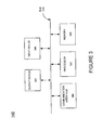
- FIG. 3 is an exemplary block diagram of the server-side address translator of FIG. 1 in an implementation consistent with the present invention
- FIG. 4 is a flowchart of processing, consistent with the present invention, for mapping address information in a manner consistent with the present invention
- FIG. 5 is a flowchart of processing, consistent with the present invention, for providing synchronized mapping
- FIG. 6 is a flowchart of processing, consistent with the present invention, for providing staggered and randomized mapping.
- Systems and methods consistent with the present invention provide dynamic mapping and translating of destination information used to transmit data packets in an unsecured network.
- a client-side device receives data to be transmitted to a server and modifies the destination address and port information.
- a dynamic address translation device at the server-side receives the modified destination address and port information and translates this information back to the real destination address and port information.
- FIG. 1 is a diagram of an exemplary system 100 in which methods and systems consistent with the present invention may be implemented.
- the system 100 includes several clients 110 , address translators 120 and 140 , server 150 and networks 130 , 160 and 170 .
- Clients 110 may each include any type of computer system, such as a personal computer or a laptop, with a connection to network 130 .
- the clients 110 receive inputs from users representing data to be transmitted via network 160 , such as data intended for server 150 .
- the clients 110 generate data packets and then transmit the packets via network 130 .
- the network 130 may include a local area network (LAN), wide area network (WAN), or another type of network.
- clients 110 may connect directly to address translator 120 . Only three clients 110 are shown for simplicity. It should be understood, however, that additional clients 110 may be included in system 100 , as described in more detail below.
- Address translator 120 may include any type of computer system, such as a mainframe, minicomputer or a personal computer. Address translator 120 includes a connection to network 130 to communicate with clients 110 . In alternative implementations, address translator 120 may include a mechanism for directly connecting to clients 110 . Address translator 120 also includes a mechanism for communicating with address translator 140 via network 160 . Address translator 120 may transmit data over network 160 via a wired, wireless or optical connection.
- the network 160 may include the Internet, a LAN, WAN, intranet or another type of network.
- Address translator 120 intercepts data packets transmitted from clients 110 and maps the destination information included with the data packets.
- the destination information may include, for example, an IP address and a TCP or UDP port.
- the address translator 120 maps the destination IP address and TCP/UDP port to another destination address and port, as described in more detail below.
- the address translator 120 then transmits the data packet with the mapped destinations via network 160 .
- the mapping of the destination information involves only the host portion of the IP address, leaving the network portion of the IP address and the resulting packet routing across network 160 unchanged.
- the address translator 140 may be any type of computer system, such as a mainframe computer, minicomputer or a personal computer.
- the address translator 140 receives data transmitted from address translator 120 and translates the mapped destination information back to the real destination information.
- the address translator 140 then transmits the data to its intended destination, via network 170 .
- Network 170 may include the Internet, a LAN, a WAN, an intranet or another type of network.
- the address translator 140 may connect directly to server 150 .
- the address translators 120 and 140 prevent the mapping of a network, such as network 170 , by unauthorized parties
- the server 150 may include any type of conventional computer system, such as a mainframe, minicomputer or personal computer, which may be used to receive and process information transmitted via network 170 .
- the server 150 may be the front-end of a company's private network and may provide access to secured databases of information and private company programs.
- FIG. 2 illustrates an exemplary address translator 120 upon which a system and method, consistent with the present invention, may be implemented.
- the address translator 120 includes a bus 210 , a processor 220 , a main memory 230 , a read only memory (ROM) 240 , a storage device 250 , an input device 260 , an output device 270 , and a communication interface 280 .
- the bus 210 permits communication among the components of the address translator 120 .
- the processor 220 may include any type of conventional processor or microprocessor that interprets and executes instructions.
- Main memory 230 may be a random access memory (RAM) or other dynamic storage device that stores information and instructions for execution by processor 220 .
- Main memory 230 may also store temporary variables or other intermediate information during execution of instructions by processor 220 .
- the ROM 240 may include a conventional ROM device or another type of static storage device that stores static information and instructions for processor 220 .
- the storage device 250 may include any type of magnetic or optical recording medium and its corresponding drive, such as a magnetic disk or optical disk and its corresponding disk drive.
- the input device 260 may include any conventional mechanism that permits an operator to input information to the address translator 120 , such as a keyboard, a mouse, a pen, voice recognition and/or biometric mechanisms, etc.
- the output device 270 may include any conventional mechanism that outputs information to the operator, including a display, a printer, a pair of speakers, etc.
- the communication interface 280 may include any transceiver-like mechanism that enables the address translator 120 to communicate with other devices and/or systems.
- the communication interface 280 may include mechanisms, such as a modem or an Ethernet interface, for communicating via a network, such as network 130 and network 160 ( FIG. 1 ).
- the communication interface 280 may include an internal network interface for receiving and transmitting data packets having real address information via network 130 and an external network interface for transmitting and receiving data packets having mapped destination information via network 160 .
- Address translator 120 performs the functions necessary to map destination information in response to processor 220 executing sequences of instructions contained in memory 230 .
- Such instructions may be read into memory 230 from another computer-readable medium, such as a data storage device 250 , or from a separate device via communication interface 280 .
- Execution of the sequences of instructions contained in memory 230 causes processor 220 to perform the process steps that will be described hereafter.
- hard-wired circuitry may be used in place of or in combination with software instructions to implement the present invention.
- the present invention is not limited to any specific combination of hardware circuitry and software.
- address translator 120 may be co-resident with client 110 on the same host device.
- the processes performed by address translator 120 may be performed by software running on client 110 , without the need for a separate address translation device. It should also be noted that multiple client-side address translators 120 may access the single server-side address translator 140 .
- FIG. 3 illustrates an exemplary address translator 140 upon which a system and method consistent with the present invention may be implemented.
- the address translator 140 includes a bus 310 , a processor 320 , a memory 330 , an input device 340 , an output device 350 , and a communication interface 360 .
- the bus 310 permits communication among the components of the address translator 140 .
- the processor 320 may include any type of conventional processor or microprocessor that interprets and executes instructions.
- the memory 330 may include a RAM or another dynamic storage device that stores information and instructions for execution by the processor 320 ; a ROM or another type of static storage device that stores static information and instructions for use by the processor 320 ; and/or some other type of magnetic or optical recording medium and its corresponding drive.
- the input device 340 may include any conventional mechanism that permits an operator to input information to the address translator 140 , such as a keyboard, a mouse, a pen, voice recognition and/or biometric mechanisms, etc.
- the output device 350 may include any conventional mechanism that outputs information to the operator, including a display, a printer, a pair of speakers, etc.
- the communication interface 360 may include any transceiver-like mechanism that enables the address translator 140 to communicate with other devices and/or systems.
- the communication interface 360 may include mechanisms for communicating via networks, such as networks 160 and 170 ( FIG. 1 ).
- the communication interface 360 may include an external network interface for receiving and transmitting data packets having mapped destination information via network 160 and an internal network interface for transmitting and receiving data packets having real address information via network 170 .
- the address translator 140 performs the functions necessary to translate the mapped destination information to the real destination information in response to processor 320 executing sequences of instructions contained in memory 330 .
- Such instructions may be read into memory 330 from another computer-readable medium or from a separate device via communication interface 360 . Execution of the sequences of instructions contained in memory 330 causes the processor 320 to perform the process steps that will be described hereafter.
- hard-wired circuitry may be used in place of or in combination with software instructions to implement the present invention.
- the present invention is not limited to any specific combination of hardware circuitry and software.
- FIG. 4 is a flowchart illustrating exemplary processing for performing address mapping and translating in a manner consistent with the present invention.
- Processing begins when a user, via a client 110 , wishes to transmit data via network 160 .
- the user enters the information into client 110 .
- the client 110 then generates a data packet with a packet header (step 410 ).
- the packet header may include the destination address of the data packet and a port identifier.
- the destination information may include a port identifier associated with a particular port on server 150 .
- the client 110 then transmits the data packet in a conventional manner via network 130 using the destination address associated with server 150 (step 410 ).
- the address translator 120 intercepts the data packet intended for server 150 (step 420 ).
- the packet at this point includes the real destination information associated with server 150 .
- the destination information may include an IP address associated with server 150 and a port identifier associated with a particular port on server 150 .
- the address translator 120 then maps the real destination information for the data packet (step 420 ).
- address translator 120 receives an IP packet having a destination address and port identifier of 4.22.161.5:1444.
- the first four numbers represent the IP address associated with server 150 and the last number represents a particular port on server 150 .
- the address translator 120 then maps the destination information to another address. For example, the address translator 120 may map the destination address and port to 4.22.161.118:289.
- the address translator 120 may perform such mapping of the real destination address and port identifier using any type of mapping algorithm.
- the mapping algorithm may employ a random “seed,” i.e., number, in conjunction with mathematical operations for changing any or all of the four numbers representing the destination address and the single number representing the port.
- the mapping algorithm mapped the fourth number in the destination address, “5,” to “118” and the port number of “1444” to “289.”
- the mapping algorithm may change any or all of the five numbers forming the destination address/port identifier.
- the mapping algorithm also employs conventional cryptographic techniques in the mapping process.
- the mapping algorithm performed by the address translator 120 may employ a “secret key” to encrypt the mapped data.
- the mapping algorithm produces cryptographically protected, unpredictable mappings of destination information. Encrypting the data further confounds network discovery by increasing the work associated with a hacker trying to infiltrate server 150 . Only a recipient, such as address translator 140 , with the secret key is then able to decrypt the data. Therefore, even when a sniffer intercepts the data packets transmitted to server 150 , the hacker cannot identify the destination information associated with the data packets without knowledge of the shared secret key.
- the address translator 120 After generating the mapped, encrypted destination information, the address translator 120 transmits the data packet via network 160 (step 430 ).
- the address translator 140 receives the data packet on the external side, i.e., non-secured side, of the interface to network 160 (step 440 ).
- the address translator 140 may then decrypt the destination information using the shared secret key associated with the algorithm used to encrypt the destination information (step 440 ).
- the address translator 140 translates the mapped address information and port identifier back to the real destination address and port identifier (step 440 ).
- the decrypting and translating processes may be performed concurrently.
- the address translator 140 translates the mapped address/port of 4.22.161.118:289 back to 4.22.161.5.1444 (i.e., the actual destination address/port of the data packet).
- the address translator 140 stores an algorithm that performs the reverse process performed by the mapping algorithm in the address translator 120 . That is, the address translator 140 remaps the mapped destination information back to the original destination information using the reverse of the process used to map the original destination information.
- the address translator 140 then transmits the data packet, using the real destination address and port identifier for server 150 , via network 170 (step 450 ).
- the real destination information is never transmitted over an unsecured network, such as network 160 .
- Hackers therefore, cannot “sniff” the real address/port identifier and are unable to map network 170 .
- the address translators 120 and 140 coordinate their mapping and translating operations to ensure that the data packet is properly routed to its destination. In other words, the address translator 120 and address translator 140 coordinate their efforts to determine when to perform the mapping/translating functions so that a destination address mapped at the client side of network 160 may be properly translated at the server side of the network 160 .
- the address translators 120 and 140 may also coordinate changes in the secret keys used to perform the mapping/translating functions. In implementations consistent with the present invention, the coordination between the address translators 120 and 140 may be synchronized, staggered or randomized, as described in detail below.
- FIG. 5 illustrates processing, consistent with the present invention, for synchronized mapping of destination information. Processing begins upon power-up of the address translator 120 and the address translator 140 . Upon power-up, the address translators 120 and 140 each begin execution of the normal start-up procedures, including execution of their respective configuration files (step 510 ).
- the configuration file for the address translator 120 stores information relating to how and when the mapping is initiated.
- the mapping may be synchronized, staggered or randomized. Assume that the mapping is synchronized. In this scenario, synchronization may be accomplished via an external shared mechanism, such as time, or by direct communication between address translators 120 and 140 .
- the address translator 120 executes its configuration file and determines when to begin mapping the real destination information (step 520 ). Similarly, the address translator 140 determines when to begin translating the received destination information back to the real destination information (step 520 ).
- the configuration file in the address translator 120 for a clock-synchronized, non-staggered algorithm might indicate that all mappings begin at the start of an hour.
- the configuration file in the address translator 140 indicates that the translating begins at the start of the hour. In this manner, the mapping/translating are synchronized using high precision clocks to ensure that data is seamlessly transmitted from clients 110 to the destinations, such as server 150 .
- the synchronized mapping may be initiated by direct communication between the address translators 120 and 140 , such as by passing synchronization packets between address translator 120 and address translator 140 .
- the address translator 120 may send a packet to the address translator 140 establishing a shared private session key to control the mappings until a subsequent exchange between the address translators 120 and 140 .
- the synchronization packet may indicate that mapping is to begin at a certain time and date. This information may optionally be encrypted.
- the address translator 140 receives the synchronization packet, decrypts the packet if necessary, and determines when to begin translating the received destination information back to the real destination information.
- the address translator 140 may optionally send an acknowledgement packet back to the address translator 120 to confirm that the message has been received and that synchronization has been established.
- the address translator 120 After synchronization is established, suppose that the address translator 120 receives a data packet intended for server 150 .
- the address translator 120 maps the destination information and transmits the packet (step 530 ).
- the address translator 140 receives the data packet, decrypts the data packet, if necessary, and translates the mapped destination information back to the real destination address (step 540 ). In this manner, destination information is dynamically mapped/translated with no impact on client 110 applications or server 150 applications.
- the configuration files for the address translator 120 and the address translator 140 may also include information indicating when to change the mapping scheme used to map/translate the destination information.
- the respective devices may include multiple algorithms for mapping/translating destination information and a schedule for when to change algorithms.
- the configuration file for address translator 120 may indicate that the mapping algorithm is to change every five minutes at 5, 10, 15, etc, minutes past the hour.
- the configuration file for address translator 140 would indicate that the translating algorithm is to change every five minutes past the hour. Frequently changing the mapping/translating algorithm makes it more difficult for a hacker to succeed in trying to map the network topology associated with network 170 or devices connected to network 170 , such as server 150 .
- the synchronization mechanism used by address translators 120 and 140 ensures consistent transitions between the mapping intervals.
- FIG. 6 illustrates processing, consistent with the present invention, for staggered and randomized mapping of network destination information.
- the mapping mechanism is a staggered or randomized.
- the address translator 120 determines what portion of the addresses to map during the particular interval of time (step 610 ).
- the address translator 140 determines what portion of the addresses are to be translated at a particular interval of time (step 610 ).
- the respective configuration files in the address translators 120 and 140 may indicate that at 12:01 AM on a particular date, that the mapping/translating is to begin for addresses between “XXX.XXX.XX.0” and “XXX.XXX.XX.100.” Additional information may indicate that at 8:00 AM on the same date, that mapping/translating is to begin for addresses between “XXX.XXX.XX.100” to “XXX.XXX.XX.200.” Further information may indicate that at 2:00 PM on the same date that mapping/translating is to begin for addresses from “XXX.XXX.XX.200” to “XXX.XXX.XX.255.”
- any portion of addresses and ports may be mapped at any particular time. It should also be noted that not all addresses are necessarily mapped at any time.
- the address translator 120 and the address translator 140 each store the particular information regarding when to perform the mapping/translating for the given destination addresses/ports. Staggering the mapping/translating in this manner makes it more difficult for a hacker to attempt to determine how the destination information is being changed.
- the staggered mapping may occur by passing packets between the address translator 120 and the address translator 140 .
- the address translator 120 may send a packet to the address translator 140 indicating that mapping is to begin for a certain set of address at a certain time and date. This information may optionally be encrypted.
- the address translator 140 receives the information, decrypts the packet if necessary, and determines when to begin translating the destination information associated with the set of addresses back to the real destination information.
- the address translator 140 may optionally send an acknowledgement packet back to the address translator 120 to confirm that the message has been received.
- Other mechanisms for identifying the particular address/ports to map at a particular time may also be used in implementations consistent with the present invention.
- the address translator 120 intercepts a data packet from client 110 (step 620 ).
- the address translator 120 determines whether the destination address transmitted with the data packet is one of the addresses included in the set of addresses that are to be mapped at that particular time (step 630 ). If the destination address is not in the set designated for mapping at that time, the address translator 120 transmits the data packet without mapping the destination information (step 640 ).
- the address translator 140 similarly receives the data packet and checks whether the destination address is in the set of addresses to be translated at that particular time (step 650 ). Assuming that the answer is “no,” the address translator 140 transmits the data packet to server 150 without translating the destination address (step 660 ).
- the address translator 120 determines that the destination address is in the set of addresses to be mapped at the particular time (step 630 ).
- the address translator 120 maps the destination information using the mapping algorithm (step 670 ).
- the address translator 120 may concurrently encrypt the destination address of the data packet while performing the mapping.
- the address translator 120 then transmits the packet.
- the address translator 140 receives the data packet, decrypts the destination address, if necessary, and similarly checks whether the destination address is in the set of addresses to be translated at that particular time (step 680 ). Assuming that the answer is “yes,” the address translator 140 translates the destination information back to the real destination information using the translation algorithm and then transmits the packet (step 690 ).
- the interval of time between mapping the first and second set of address may be fixed.
- the first set of addresses may be mapped beginning at 12:01 AM
- the second set may be mapped beginning at 2:01 AM
- the third set may be remapped at 4:01 AM, and so on, where the interval between mappings is set to two hours.
- the interval between the mappings may be random, i.e., generated by a pseudo-random number generator program running concurrently on the address translator 120 and the address translator 140 . Changing the interval between the mappings makes it more difficult for a hacker to determine the mapping scheme.
- the particular set of addresses to be mapped at a given time may also be randomized in a similar manner.
- a random number generator program running concurrently on the address translator 120 and the address translator 140 may generate a random set of addresses to map/translate at a particular time. Adding the additional randomness to the mapping/translating scheme further increases the work associated with a hacker trying to map the network.
- various elements of the synchronized, staggered and randomized mapping schemes may be combined in any number of ways to make the particular mapping scheme harder to detect.
- a randomized mapping may be combined with a staggered mapping to randomize the interval that various destination addresses/ports are mapped and the interval between changing the mapping scheme and/or keys used for any or all of the addresses/ports.
- mapping/translating functions are performed with no impact to clients 110 or to devices on network 170 , such as server 150 . That is, the clients 110 and server 150 may perform their tasks in their normal manner while the mapping/translating functions are performed.
- Another advantage of the invention is that the types of mapping/translating performed may be combined in any number of ways.
- the present invention has been described with the example of the address translator 120 performing the mapping and the address translator 140 performing the translating. It should also be understood that when data packets are transmitted from server 150 to clients 110 , the reverse process may be used. That is, since conventional data packets also include a source address, a hacker may attempt to map network 170 by using the source address information transmitted from server 150 . Therefore, the address translator 140 may perform the mapping function and the address translator 120 may perform the translating function. In this manner, data packets transmitted in either direction over network 160 are protected from network discovery by using mapped destination information and encryption techniques.
- address translator 140 communicates with a single host device, such as server 150 , via network 170 .
- server 150 or other hosts on network 170 may themselves be clients of other servers located elsewhere on network 160 .
- address translator 140 maps the source address of outgoing data packets and translates the destination address of replies. In this manner, any data transmitted over an unsecured network, such as network 160 is protected from hackers attempting to perform network discovery.
- the present invention is described in an environment where the address translator 140 translates the mapped destination information back to the real destination information.
- a host device such as server 150 , may perform the translating functions performed by the address translator 140 .
Abstract
Description
Claims (7)
Priority Applications (1)
| Application Number | Priority Date | Filing Date | Title |
|---|---|---|---|
| US12/832,300 US9237059B2 (en) | 2000-06-14 | 2010-07-08 | Method and apparatus for dynamic mapping |
Applications Claiming Priority (2)
| Application Number | Priority Date | Filing Date | Title |
|---|---|---|---|
| US09/594,100 US7757272B1 (en) | 2000-06-14 | 2000-06-14 | Method and apparatus for dynamic mapping |
| US12/832,300 US9237059B2 (en) | 2000-06-14 | 2010-07-08 | Method and apparatus for dynamic mapping |
Related Parent Applications (1)
| Application Number | Title | Priority Date | Filing Date |
|---|---|---|---|
| US09/594,100 Continuation US7757272B1 (en) | 2000-06-14 | 2000-06-14 | Method and apparatus for dynamic mapping |
Publications (2)
| Publication Number | Publication Date |
|---|---|
| US20100274923A1 US20100274923A1 (en) | 2010-10-28 |
| US9237059B2 true US9237059B2 (en) | 2016-01-12 |
Family
ID=42314233
Family Applications (2)
| Application Number | Title | Priority Date | Filing Date |
|---|---|---|---|
| US09/594,100 Active 2027-01-28 US7757272B1 (en) | 2000-06-14 | 2000-06-14 | Method and apparatus for dynamic mapping |
| US12/832,300 Expired - Fee Related US9237059B2 (en) | 2000-06-14 | 2010-07-08 | Method and apparatus for dynamic mapping |
Family Applications Before (1)
| Application Number | Title | Priority Date | Filing Date |
|---|---|---|---|
| US09/594,100 Active 2027-01-28 US7757272B1 (en) | 2000-06-14 | 2000-06-14 | Method and apparatus for dynamic mapping |
Country Status (1)
| Country | Link |
|---|---|
| US (2) | US7757272B1 (en) |
Families Citing this family (23)
| Publication number | Priority date | Publication date | Assignee | Title |
|---|---|---|---|---|
| US8464334B1 (en) * | 2007-04-18 | 2013-06-11 | Tara Chand Singhal | Systems and methods for computer network defense II |
| US8499340B2 (en) * | 2007-05-29 | 2013-07-30 | Telefonaktiebolaget L M Ericsson (Publ) | IMS network identity management |
| US8934487B2 (en) * | 2009-11-05 | 2015-01-13 | Telefonaktiebolaget Lm Ericsson (Publ) | Network topology concealment using address permutation |
| US8805672B2 (en) | 2011-06-30 | 2014-08-12 | International Business Machines Corporation | Translation cache prediction |
| US8935780B2 (en) * | 2012-02-09 | 2015-01-13 | Harris Corporation | Mission management for dynamic computer networks |
| US8898795B2 (en) | 2012-02-09 | 2014-11-25 | Harris Corporation | Bridge for communicating with a dynamic computer network |
| US8819818B2 (en) | 2012-02-09 | 2014-08-26 | Harris Corporation | Dynamic computer network with variable identity parameters |
| US8935786B2 (en) | 2012-05-01 | 2015-01-13 | Harris Corporation | Systems and methods for dynamically changing network states |
| US8898782B2 (en) | 2012-05-01 | 2014-11-25 | Harris Corporation | Systems and methods for spontaneously configuring a computer network |
| US9130907B2 (en) * | 2012-05-01 | 2015-09-08 | Harris Corporation | Switch for communicating data in a dynamic computer network |
| US9075992B2 (en) * | 2012-05-01 | 2015-07-07 | Harris Corporation | Systems and methods for identifying, deterring and/or delaying attacks to a network using shadow networking techniques |
| US9154458B2 (en) | 2012-05-01 | 2015-10-06 | Harris Corporation | Systems and methods for implementing moving target technology in legacy hardware |
| US8959573B2 (en) | 2012-05-01 | 2015-02-17 | Harris Corporation | Noise, encryption, and decoys for communications in a dynamic computer network |
| US8966626B2 (en) | 2012-05-01 | 2015-02-24 | Harris Corporation | Router for communicating data in a dynamic computer network |
| US9621495B1 (en) * | 2012-12-10 | 2017-04-11 | Jeffrey Brian Shumate | Anonymous messaging proxy |
| US9129118B1 (en) * | 2013-05-03 | 2015-09-08 | Amazon Technologies, Inc. | Mapping identifying information |
| US9501431B1 (en) * | 2013-09-05 | 2016-11-22 | Google Inc. | Remote control monitoring of data center equipment |
| US9503324B2 (en) | 2013-11-05 | 2016-11-22 | Harris Corporation | Systems and methods for enterprise mission management of a computer network |
| US9264496B2 (en) | 2013-11-18 | 2016-02-16 | Harris Corporation | Session hopping |
| US9338183B2 (en) | 2013-11-18 | 2016-05-10 | Harris Corporation | Session hopping |
| US10122708B2 (en) | 2013-11-21 | 2018-11-06 | Harris Corporation | Systems and methods for deployment of mission plans using access control technologies |
| US10313223B2 (en) | 2016-12-14 | 2019-06-04 | Level 3 Communications, Llc | Object integrity verification in a content delivery network (CDN) |
| CN115996210B (en) * | 2023-03-23 | 2023-06-27 | 湖南盾神科技有限公司 | Address port hopping method of source variable mode |
Citations (1)
| Publication number | Priority date | Publication date | Assignee | Title |
|---|---|---|---|---|
| US6415329B1 (en) * | 1998-03-06 | 2002-07-02 | Massachusetts Institute Of Technology | Method and apparatus for improving efficiency of TCP/IP protocol over high delay-bandwidth network |
Family Cites Families (24)
| Publication number | Priority date | Publication date | Assignee | Title |
|---|---|---|---|---|
| US5230045A (en) * | 1986-11-12 | 1993-07-20 | Xerox Corporation | Multiple address space system including address translator for receiving virtual addresses from bus and providing real addresses on the bus |
| US5640528A (en) * | 1991-10-24 | 1997-06-17 | Intel Corporation | Method and apparatus for translating addresses using mask and replacement value registers |
| DE4411450C1 (en) * | 1994-04-01 | 1995-03-30 | Daimler Benz Ag | Vehicle security device with electronic use authorisation encoding |
| US6189077B1 (en) * | 1994-12-15 | 2001-02-13 | Texas Instruments Incorporated | Two computer access circuit using address translation into common register file |
| WO1997000480A1 (en) * | 1995-06-15 | 1997-01-03 | Intel Corporation | Architecture for an i/o processor that integrates a pci to pci bridge |
| US5757924A (en) * | 1995-09-18 | 1998-05-26 | Digital Secured Networks Techolognies, Inc. | Network security device which performs MAC address translation without affecting the IP address |
| US6104717A (en) * | 1995-11-03 | 2000-08-15 | Cisco Technology, Inc. | System and method for providing backup machines for implementing multiple IP addresses on multiple ports |
| US5898830A (en) * | 1996-10-17 | 1999-04-27 | Network Engineering Software | Firewall providing enhanced network security and user transparency |
| US5923654A (en) * | 1996-04-25 | 1999-07-13 | Compaq Computer Corp. | Network switch that includes a plurality of shared packet buffers |
| US6073224A (en) * | 1996-07-01 | 2000-06-06 | Sun Microsystems, Inc. | Network interface circuit with replacement circuitry and method for segregating memory in an address translation unit with locked and unlocked regions |
| EP0951767A2 (en) * | 1997-01-03 | 1999-10-27 | Fortress Technologies, Inc. | Improved network security device |
| US6130892A (en) * | 1997-03-12 | 2000-10-10 | Nomadix, Inc. | Nomadic translator or router |
| US5953511A (en) * | 1997-04-08 | 1999-09-14 | National Instruments Corporation | PCI bus to IEEE 1394 bus translator |
| JP3641112B2 (en) * | 1997-09-05 | 2005-04-20 | 株式会社東芝 | Packet relay device, mobile computer device, mobile computer management device, packet relay method, packet transmission method, and mobile computer location registration method |
| US6170012B1 (en) * | 1997-09-12 | 2001-01-02 | Lucent Technologies Inc. | Methods and apparatus for a computer network firewall with cache query processing |
| US7032242B1 (en) * | 1998-03-05 | 2006-04-18 | 3Com Corporation | Method and system for distributed network address translation with network security features |
| US7039688B2 (en) * | 1998-11-12 | 2006-05-02 | Ricoh Co., Ltd. | Method and apparatus for automatic network configuration |
| US6484257B1 (en) * | 1999-02-27 | 2002-11-19 | Alonzo Ellis | System and method for maintaining N number of simultaneous cryptographic sessions using a distributed computing environment |
| US6507908B1 (en) * | 1999-03-04 | 2003-01-14 | Sun Microsystems, Inc. | Secure communication with mobile hosts |
| US6907034B1 (en) * | 1999-04-08 | 2005-06-14 | Intel Corporation | Out-of-band signaling for network based computer session synchronization |
| US6957346B1 (en) * | 1999-06-15 | 2005-10-18 | Ssh Communications Security Ltd. | Method and arrangement for providing security through network address translations using tunneling and compensations |
| US6625141B1 (en) * | 1999-06-18 | 2003-09-23 | Telefonaktiebolaget L M Ericsson (Publ) | System and method for providing value-added services (VAS) in an integrated telecommunications network using session initiation protocol (SIP) |
| US6970941B1 (en) * | 1999-12-10 | 2005-11-29 | Sun Microsystems, Inc. | System and method for separating addresses from the delivery scheme in a virtual private network |
| US6581130B1 (en) * | 2000-04-04 | 2003-06-17 | Hewlett Packard Development Company, L.P. | Dynamic remapping of address registers for address translation between multiple busses |
-
2000
- 2000-06-14 US US09/594,100 patent/US7757272B1/en active Active
-
2010
- 2010-07-08 US US12/832,300 patent/US9237059B2/en not_active Expired - Fee Related
Patent Citations (1)
| Publication number | Priority date | Publication date | Assignee | Title |
|---|---|---|---|---|
| US6415329B1 (en) * | 1998-03-06 | 2002-07-02 | Massachusetts Institute Of Technology | Method and apparatus for improving efficiency of TCP/IP protocol over high delay-bandwidth network |
Non-Patent Citations (1)
| Title |
|---|
| Kewley, Dorene, et al., "Dynamic Approaches to Thwart Adversary Intelligence Gathering," 0-7695-1212-7-01, Jul. 2001, IEEE, pp. 176-185. |
Also Published As
| Publication number | Publication date |
|---|---|
| US7757272B1 (en) | 2010-07-13 |
| US20100274923A1 (en) | 2010-10-28 |
Similar Documents
| Publication | Publication Date | Title |
|---|---|---|
| US9237059B2 (en) | Method and apparatus for dynamic mapping | |
| US6751728B1 (en) | System and method of transmitting encrypted packets through a network access point | |
| US7039713B1 (en) | System and method of user authentication for network communication through a policy agent | |
| US7043633B1 (en) | Method and apparatus for providing adaptive self-synchronized dynamic address translation | |
| US8024560B1 (en) | Systems and methods for securing multimedia transmissions over the internet | |
| US9300638B2 (en) | Method and apparatus for providing adaptive self-synchronized dynamic address translation as an intrusion detection sensor | |
| US6826684B1 (en) | Sliding scale adaptive self-synchronized dynamic address translation | |
| JP4464963B2 (en) | Location privacy for Internet protocol networks using cryptographically protected prefixes | |
| US7058718B2 (en) | Blended SYN cookies | |
| US7386881B2 (en) | Method for mapping security associations to clients operating behind a network address translation device | |
| EP1583319B1 (en) | Authenticated exchange of public information using electronic mail | |
| US20040260921A1 (en) | Cryptographic method, system and engine for enciphered message transmission | |
| US20060182124A1 (en) | Cipher Key Exchange Methodology | |
| US20040123143A1 (en) | Secure communication overlay using IP address hopping | |
| JPWO2005015827A1 (en) | Communication system, communication device, communication method, and communication program for realizing the same | |
| US20090327730A1 (en) | Apparatus and method for encrypted communication processing | |
| CA2321407C (en) | Security mechanisms and architecture for collaborative systems using tuple space | |
| US20080072280A1 (en) | Method and system to control access to a secure asset via an electronic communications network | |
| EP1980084B1 (en) | Packet redirection in a communication network | |
| US20080267395A1 (en) | Apparatus and method for encrypted communication processing | |
| Alden et al. | The AltaVista tunnel: Using the Internet to extend corporate networks | |
| CN111224968A (en) | Secure communication method for randomly selecting transfer server | |
| KR20200002599A (en) | Server apparatus, client apparatus and method for communicating based on network address mutation | |
| JP2008182649A (en) | Encrypted packet communication system | |
| Hansen et al. | DevCom: Device communities for user-friendly and trustworthy communication, sharing, and collaboration |
Legal Events
| Date | Code | Title | Description |
|---|---|---|---|
| AS | Assignment |
Owner name: BBNT SOLUTIONS LLC, MASSACHUSETTS Free format text: ASSIGNMENT OF ASSIGNORS INTEREST;ASSIGNOR:DEAN, MICHAEL ANTHONY;REEL/FRAME:026378/0515 Effective date: 20010406 Owner name: VERIZON CORPORATE SERVICES GROUP INC., NEW JERSEY Free format text: ASSIGNMENT OF ASSIGNORS INTEREST;ASSIGNOR:BBNT SOLUTIONS LLC;REEL/FRAME:026379/0047 Effective date: 20040503 Owner name: LEVEL 3 COMMUNICATIONS, LLC, COLORADO Free format text: ASSIGNMENT OF ASSIGNORS INTEREST;ASSIGNOR:GENUITY, INC.;REEL/FRAME:026381/0599 Effective date: 20030204 Owner name: GENUITY, INC., MASSACHUSETTS Free format text: ASSIGNMENT OF ASSIGNORS INTEREST;ASSIGNOR:DEAN, MICHAEL ANTHONY;REEL/FRAME:026378/0515 Effective date: 20010406 Owner name: BBN TECHNOLOGIES OPERATING CORP., MASSACHUSETTS Free format text: MERGER;ASSIGNOR:BBNT SOLUTIONS LLC;REEL/FRAME:026379/0398 Effective date: 20051122 Owner name: RAYTHEON BBN TECHNOLOGIES CORP., MASSACHUSETTS Free format text: CHANGE OF NAME;ASSIGNOR:BBN TECHNOLOGIES CORP.;REEL/FRAME:026382/0102 Effective date: 20091027 Owner name: BBNT SOLUTIONS LLC, MASSACHUSETTS Free format text: ASSIGNMENT OF ASSIGNORS INTEREST;ASSIGNOR:BBNT SOLUTIONS LLC;REEL/FRAME:026379/0047 Effective date: 20040503 Owner name: BBN TECHNOLOGIES CORP., MASSACHUSETTS Free format text: CHANGE OF NAME;ASSIGNOR:BBN TECHNOLOGIES OPERATING CORP.;REEL/FRAME:026382/0048 Effective date: 20051201 |
|
| ZAAA | Notice of allowance and fees due |
Free format text: ORIGINAL CODE: NOA |
|
| ZAAB | Notice of allowance mailed |
Free format text: ORIGINAL CODE: MN/=. |
|
| STCF | Information on status: patent grant |
Free format text: PATENTED CASE |
|
| MAFP | Maintenance fee payment |
Free format text: PAYMENT OF MAINTENANCE FEE, 4TH YEAR, LARGE ENTITY (ORIGINAL EVENT CODE: M1551); ENTITY STATUS OF PATENT OWNER: LARGE ENTITY Year of fee payment: 4 |
|
| FEPP | Fee payment procedure |
Free format text: MAINTENANCE FEE REMINDER MAILED (ORIGINAL EVENT CODE: REM.); ENTITY STATUS OF PATENT OWNER: LARGE ENTITY |
|
| LAPS | Lapse for failure to pay maintenance fees |
Free format text: PATENT EXPIRED FOR FAILURE TO PAY MAINTENANCE FEES (ORIGINAL EVENT CODE: EXP.); ENTITY STATUS OF PATENT OWNER: LARGE ENTITY |
|
| STCH | Information on status: patent discontinuation |
Free format text: PATENT EXPIRED DUE TO NONPAYMENT OF MAINTENANCE FEES UNDER 37 CFR 1.362 |
|
| FP | Lapsed due to failure to pay maintenance fee |
Effective date: 20240112 |