US9233418B2 - Cast-in cemented carbide components - Google Patents
Cast-in cemented carbide components Download PDFInfo
- Publication number
- US9233418B2 US9233418B2 US12/267,059 US26705908A US9233418B2 US 9233418 B2 US9233418 B2 US 9233418B2 US 26705908 A US26705908 A US 26705908A US 9233418 B2 US9233418 B2 US 9233418B2
- Authority
- US
- United States
- Prior art keywords
- cemented carbide
- steel
- zone
- content
- phase
- Prior art date
- Legal status (The legal status is an assumption and is not a legal conclusion. Google has not performed a legal analysis and makes no representation as to the accuracy of the status listed.)
- Active, expires
Links
Images


Classifications
-
- B—PERFORMING OPERATIONS; TRANSPORTING
- B22—CASTING; POWDER METALLURGY
- B22D—CASTING OF METALS; CASTING OF OTHER SUBSTANCES BY THE SAME PROCESSES OR DEVICES
- B22D19/00—Casting in, on, or around objects which form part of the product
- B22D19/06—Casting in, on, or around objects which form part of the product for manufacturing or repairing tools
-
- B—PERFORMING OPERATIONS; TRANSPORTING
- B22—CASTING; POWDER METALLURGY
- B22D—CASTING OF METALS; CASTING OF OTHER SUBSTANCES BY THE SAME PROCESSES OR DEVICES
- B22D19/00—Casting in, on, or around objects which form part of the product
- B22D19/02—Casting in, on, or around objects which form part of the product for making reinforced articles
-
- C—CHEMISTRY; METALLURGY
- C22—METALLURGY; FERROUS OR NON-FERROUS ALLOYS; TREATMENT OF ALLOYS OR NON-FERROUS METALS
- C22C—ALLOYS
- C22C38/00—Ferrous alloys, e.g. steel alloys
- C22C38/02—Ferrous alloys, e.g. steel alloys containing silicon
-
- C—CHEMISTRY; METALLURGY
- C22—METALLURGY; FERROUS OR NON-FERROUS ALLOYS; TREATMENT OF ALLOYS OR NON-FERROUS METALS
- C22C—ALLOYS
- C22C38/00—Ferrous alloys, e.g. steel alloys
- C22C38/04—Ferrous alloys, e.g. steel alloys containing manganese
-
- C—CHEMISTRY; METALLURGY
- C22—METALLURGY; FERROUS OR NON-FERROUS ALLOYS; TREATMENT OF ALLOYS OR NON-FERROUS METALS
- C22C—ALLOYS
- C22C38/00—Ferrous alloys, e.g. steel alloys
- C22C38/18—Ferrous alloys, e.g. steel alloys containing chromium
- C22C38/40—Ferrous alloys, e.g. steel alloys containing chromium with nickel
- C22C38/44—Ferrous alloys, e.g. steel alloys containing chromium with nickel with molybdenum or tungsten
Definitions
- the present invention relates to cemented carbide components which are cast into low carbon steel.
- the components are especially suitable for roller cone bits, impact rock crusher arm/impellers, point attack tools, dredging teeth and sliding wear parts.
- U.S. Pat. No. 4,119,459 discloses a composite body with cemented carbide and a matrix of graphitic cast iron-base alloy with a carbon content of 2.5-6%.
- U.S. Pat. No. 4,584,020 and U.S. Pat. No. 5,066,546 claim that the steel matrix should have a carbon content between 1.5 and 2.5%.
- U.S. Pat. No. 4,608,318 discloses a powder metallurgical method to obtain composite material bodies during solid state sintering and bonding the metal compact to said compact.
- U.S. Pat. No. 6,171,713 describes a composite of white iron alloys and cemented carbide-granules. The melting point is 1480-1525° C.
- WO 03/049889 describes consolidated hard materials, method of manufacture and applications. The consolidation takes place below the liquidus temperature of the binder metal using rapid omnidirectional compaction (ROC) or hot isostatic pressing (HIP).
- ROC rapid omnidirectional compaction
- the ductile cast iron used in the prior art has generally a low hardness of about 38 HRC and low alloy steel casting has a hardness of between 40 and 53 HRC.
- the matrix of a low alloy steel will have about twice the strength of a comparable cast iron product according to prior art.
- cemented carbide is preferably cast into an iron alloy with relatively high carbon content to form a body which body is subsequently cast into an iron alloy with lower carbon content, e.g., U.S. Pat. No. 4,584,020 and U.S. Pat. No. 5,066,546.
- FIG. 1 is a light optical micrograph of the transition zone cemented carbide/steel after etching with Murakami and Nital.
- FIG. 2 is similar but in higher magnification.
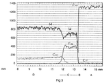
- FIG. 3 shows the distribution of W, Co, Fe and Cr along a line perpendicular to the transition zone.
- cemented carbide is cast in a steel with low carbon content by casting at a very well controlled temperature during the casting procedure and using a cemented carbide with a carbon content close to graphite formation.
- the steel is composed of a Cr, Ni, Mo low alloy steel material with a melting point of about 1450 to about 1550° C.
- the hardness of the steel is between about 45 and about 55 HRC.
- the invention is applicable to WC-based cemented carbides with a binder phase of Co and/or Ni preferably with a carbon content close to formation of free graphite which in case of a cemented carbide with cobalt binder phase means that the magnetic cobalt content is from about 0.9 to about 1.0 of the nominal cobalt content.
- the hardness of the cemented carbide is from about 800 to about 1750 HV3. Up to about 5 wt-% of carbides of the elements Ti, Cr, Nb, Ta, V can be present.
- the cemented carbide has a binder phase content of from about 10 to about 25 wt-% Co and/or Ni with WC having a grain size between about 0.5 and about 7 ⁇ m.
- the cemented carbide has a binder phase content of from about 9 to about 15 wt-% Co and/or Ni in WC with a grain size between about 2 and about 10 ⁇ m.
- the cemented carbide has a binder phase content of from about 5 to about 9 wt-% Co and/or Ni with WC with a grain size between about 2 and about 15 ⁇ m.
- the cemented carbide has a binder phase content of from about 10 to about 25 wt-% Co and/or Ni in WC with a grain size between about 2 and about 10 ⁇ m.
- the transition zone between the cemented carbide and the steel exhibits a good bond essentially free of voids and cracks. A few cracks in the zone between the steel and the cemented carbide will, however, not seriously affect performance of the product.
- transition zone there is a thin eta-phase zone with a thickness between about 50 and about 200 ⁇ m (B).
- cemented carbide adjacent to the eta-phase zone there is an iron containing transition zone with a width of about 0.5 to about 2 mm (C).
- zone with enriched carbon content (E) with a width of between about 10 and about 100 ⁇ m.
- the cemented carbide part is fixed in a mold and melted steel is poured into the mold.
- the temperature of the melt during the pouring is between about 1550 and about 1650° C.
- the cemented carbide body is pre-heated by allowing the melt passing through the mold round the cemented carbide body. Cooling is performed in free air. After the casting, conventional types of heat treatment are performed in order to harden and anneal the steel.
- the steel according to the invention exhibits good bonding to the cemented carbide. This good bonding is due to the combination of the steel type with low carbon content exhibiting a decarburizing of the outer part of the cemented carbide to form the microstructure within the cemented carbide and the steel without brittle hard phases. The thin eta-phase zone does not affect the brittleness of the cast product.
- the melting temperature of the steel during the casting should be slightly higher than the melting point of the binder phase of the cemented carbide in the surface zone of the cemented carbide body.
- Cylindrical rods of cemented carbide, with a diameter of 22 mm and length 120 mm with a composition of 5 wt-% Ni and 10 wt-% Co and rest WC with a grain size of 4 ⁇ m were prepared by conventional powder metallurgical techniques.
- the carbon content was 5.2 wt % and the hardness 1140 HV3.
- the rods were fixed in molds for the manufacturing of dredge teeth to fit the VOSTA T4 system for use in dredge cutter heads.
- a steel of type CNM85 with a composition of 0.26% C, 1.5% Si, 1.2% Mn, 1.4% Cr, 0.5% Ni, 0.2% Mo, Ceq 0.78, was melted and the melt was poured into the molds at a temperature of 1570° C.
- the cemented carbide body was pre-heated by allowing the melt passing through the mold round the cemented carbide body. After cooling in air, the teeth were normalized at 950° C. and hardened at 920° C. Annealing at 250° C. was the final heat treatment step before grinding to final shape.
- One tooth was chosen for metallurgical investigation of the transition zone cemented carbide/steel of the tooth.
- a cross section of the tooth was prepared by cutting, grinding and polishing.
- the transition zone cemented carbide/steel was examined in a light optical microscope, LOM.
- the LOM study was made on unetched as well as Murakami and Nital etched surface, see FIG. 1 and FIG. 2 .
- the bond between the steel and the cemented carbide was good and essentially without voids or cracks.
- B Between the cemented carbide and the steel there was an eta-phase zone 100 ⁇ m thick, B.
- In the cemented carbide there was an iron containing transition zone, C, with a thickness of 1.5 mm on top of the unaffected cemented carbide, D.
- Example 1 was repeated with bodies of two cemented carbide grades.
- One grade had a composition of 15 wt-% Co, rest WC with a grain size of 3 ⁇ m, a magnetic Co content of 14 wt-% and a hardness of 1070 HV3.
- the other grade had a composition of 10 wt-% Co, rest WC with a grain size of 4 ⁇ m, a magnetic Co content of 9.6 wt-% and a hardness of 1175 HV3.
- the cemented carbide bodies were in this case cylindrical chisel shaped buttons with an outer diameter of 18 mm.
- buttons were fixed in a suitable mold in such a way that a conical cutter was obtained.
- the buttons with the lower Co content was fixed in the outer radius of the cone and the inner top position had buttons with the higher Co content.
- the cones were provided with a bore for the bearing.
- the finished cutters were examined in the same way as in example 1 with essentially the same results.
- Example 1 was repeated with a grade with a composition of 20 wt-% Co, rest WC with a grain size of 2 ⁇ m.
- the magnetic Co content was 18.4 wt-% and the hardness 900 HV3.
Abstract
Description
-
- A—steel,
- B—eta-phase zone,
- C—transition zone in the cemented carbide,
- D—unaffected cemented carbide and
- E—carbon enriched zone in the steel.
Claims (12)
Applications Claiming Priority (3)
| Application Number | Priority Date | Filing Date | Title |
|---|---|---|---|
| SE0702488 | 2007-11-09 | ||
| SE0702488 | 2007-11-09 | ||
| SE0702488-8 | 2007-11-09 |
Publications (2)
| Publication Number | Publication Date |
|---|---|
| US20090148336A1 US20090148336A1 (en) | 2009-06-11 |
| US9233418B2 true US9233418B2 (en) | 2016-01-12 |
Family
ID=40626005
Family Applications (1)
| Application Number | Title | Priority Date | Filing Date |
|---|---|---|---|
| US12/267,059 Active 2030-07-16 US9233418B2 (en) | 2007-11-09 | 2008-11-07 | Cast-in cemented carbide components |
Country Status (12)
| Country | Link |
|---|---|
| US (1) | US9233418B2 (en) |
| EP (1) | EP2219807B1 (en) |
| JP (1) | JP5576287B2 (en) |
| CN (1) | CN101848781B (en) |
| AU (1) | AU2008325291B2 (en) |
| CA (1) | CA2704068C (en) |
| DK (1) | DK2219807T3 (en) |
| ES (1) | ES2505740T3 (en) |
| PL (1) | PL2219807T3 (en) |
| PT (1) | PT2219807T (en) |
| RU (1) | RU2479379C2 (en) |
| WO (1) | WO2009061274A1 (en) |
Families Citing this family (7)
| Publication number | Priority date | Publication date | Assignee | Title |
|---|---|---|---|---|
| WO2010136055A1 (en) * | 2009-05-29 | 2010-12-02 | Metalogenia S.A. | Wear element for earth working machine with enhanced wear resistance |
| WO2010136207A1 (en) | 2009-05-29 | 2010-12-02 | Metalogenia, S.L. | Wear element for earth/rock working operations with enhanced wear resistance |
| KR102220849B1 (en) * | 2012-11-08 | 2021-02-25 | 하이페리온 매터리얼즈 앤드 테크놀로지스 (스웨덴) 에이비 | Low carbon steel and cemented carbide wear part |
| CN103028720B (en) * | 2012-12-11 | 2014-11-26 | 成都现代万通锚固技术有限公司 | Manufacturing method of self-drilling anchor rod bit |
| US20150259985A1 (en) * | 2014-03-11 | 2015-09-17 | Varel International Ind., L.P. | Short matrix drill bits and methodologies for manufacturing short matrix drill bits |
| US9725794B2 (en) | 2014-12-17 | 2017-08-08 | Kennametal Inc. | Cemented carbide articles and applications thereof |
| CN113145829A (en) * | 2021-01-29 | 2021-07-23 | 自贡长城硬面材料有限公司 | Preparation method of composite wear-resistant element |
Citations (15)
| Publication number | Priority date | Publication date | Assignee | Title |
|---|---|---|---|---|
| US4024902A (en) * | 1975-05-16 | 1977-05-24 | Baum Charles S | Method of forming metal tungsten carbide composites |
| US4101318A (en) | 1976-12-10 | 1978-07-18 | Erwin Rudy | Cemented carbide-steel composites for earthmoving and mining applications |
| US4119459A (en) | 1976-02-05 | 1978-10-10 | Sandvik Aktiebolag | Composite body consisting of cemented carbide and cast alloy |
| DE3515975A1 (en) | 1984-06-07 | 1985-12-12 | Eisenhütte Prinz Rudolph, Zweigniederlassung der Salzgitter Maschinen und Anlagen AG, 4408 Dülmen | Method and apparatus for the production of cutting rings with a sintered-carbide cutting edge for cutting away geological formations, in particular for boring with cutter rollers |
| US4584020A (en) | 1982-12-06 | 1986-04-22 | Santrade Limited | Wear part with high wear strength |
| US4608318A (en) | 1981-04-27 | 1986-08-26 | Kennametal Inc. | Casting having wear resistant compacts and method of manufacture |
| US5066546A (en) * | 1989-03-23 | 1991-11-19 | Kennametal Inc. | Wear-resistant steel castings |
| JPH06218520A (en) | 1992-10-28 | 1994-08-09 | Nippon Tungsten Co Ltd | Manufacture of drilling bit |
| JPH07214288A (en) | 1994-02-08 | 1995-08-15 | Komatsu Ltd | Surface hardening material of cast steel parts, casting mold and surface hardening method |
| US5785109A (en) | 1994-05-13 | 1998-07-28 | Komatsu Ltd. | Method for casting wear resistant parts |
| US6033791A (en) | 1997-04-04 | 2000-03-07 | Smith And Stout Research And Development, Inc. | Wear resistant, high impact, iron alloy member and method of making the same |
| EP1048750A1 (en) | 1999-04-26 | 2000-11-02 | Sandvik Aktiebolag | Coated cutting tool |
| JP2000352292A (en) | 1999-06-11 | 2000-12-19 | Nippon Tungsten Co Ltd | Crushing tool and cemented carbide material tip for crushing tool |
| WO2003049889A2 (en) | 2001-12-05 | 2003-06-19 | Baker Hughes Incorporated | Consolidated hard materials, methods of manufacture, and applications |
| EP1798310A2 (en) | 2005-12-14 | 2007-06-20 | Sandvik Intellectual Property AB | Cemented carbide inserts for wear demanding parting and grooving in heat resistant super alloys (HRSA) and stainless steels |
Family Cites Families (5)
| Publication number | Priority date | Publication date | Assignee | Title |
|---|---|---|---|---|
| US4907665A (en) | 1984-09-27 | 1990-03-13 | Smith International, Inc. | Cast steel rock bit cutter cones having metallurgically bonded cutter inserts |
| US4764255A (en) | 1987-03-13 | 1988-08-16 | Sandvik Ab | Cemented carbide tool |
| JP2596106B2 (en) | 1988-12-27 | 1997-04-02 | 住友重機械鋳鍛株式会社 | Combined drilling tooth |
| RU2006371C1 (en) | 1992-01-21 | 1994-01-30 | Александр Васильевич Румянцев | Multilayer composite material, method for its manufacture and article made of this material |
| CN1050638C (en) | 1995-09-12 | 2000-03-22 | 易林清 | Cr containing hard alloy |
-
2008
- 2008-11-06 CA CA2704068A patent/CA2704068C/en active Active
- 2008-11-06 WO PCT/SE2008/051267 patent/WO2009061274A1/en active Application Filing
- 2008-11-06 ES ES08846660.2T patent/ES2505740T3/en active Active
- 2008-11-06 DK DK08846660.2T patent/DK2219807T3/en active
- 2008-11-06 CN CN2008801149887A patent/CN101848781B/en active Active
- 2008-11-06 JP JP2010533041A patent/JP5576287B2/en active Active
- 2008-11-06 PT PT88466602T patent/PT2219807T/en unknown
- 2008-11-06 PL PL08846660T patent/PL2219807T3/en unknown
- 2008-11-06 AU AU2008325291A patent/AU2008325291B2/en active Active
- 2008-11-06 EP EP08846660.2A patent/EP2219807B1/en active Active
- 2008-11-06 RU RU2010123375/02A patent/RU2479379C2/en active
- 2008-11-07 US US12/267,059 patent/US9233418B2/en active Active
Patent Citations (19)
| Publication number | Priority date | Publication date | Assignee | Title |
|---|---|---|---|---|
| US4024902A (en) * | 1975-05-16 | 1977-05-24 | Baum Charles S | Method of forming metal tungsten carbide composites |
| US4119459A (en) | 1976-02-05 | 1978-10-10 | Sandvik Aktiebolag | Composite body consisting of cemented carbide and cast alloy |
| US4101318A (en) | 1976-12-10 | 1978-07-18 | Erwin Rudy | Cemented carbide-steel composites for earthmoving and mining applications |
| US4608318A (en) | 1981-04-27 | 1986-08-26 | Kennametal Inc. | Casting having wear resistant compacts and method of manufacture |
| US4584020A (en) | 1982-12-06 | 1986-04-22 | Santrade Limited | Wear part with high wear strength |
| DE3515975A1 (en) | 1984-06-07 | 1985-12-12 | Eisenhütte Prinz Rudolph, Zweigniederlassung der Salzgitter Maschinen und Anlagen AG, 4408 Dülmen | Method and apparatus for the production of cutting rings with a sintered-carbide cutting edge for cutting away geological formations, in particular for boring with cutter rollers |
| US5337801A (en) | 1989-03-23 | 1994-08-16 | Kennametal Inc. | Wear-resistant steel castings |
| US5066546A (en) * | 1989-03-23 | 1991-11-19 | Kennametal Inc. | Wear-resistant steel castings |
| JPH06218520A (en) | 1992-10-28 | 1994-08-09 | Nippon Tungsten Co Ltd | Manufacture of drilling bit |
| JPH07214288A (en) | 1994-02-08 | 1995-08-15 | Komatsu Ltd | Surface hardening material of cast steel parts, casting mold and surface hardening method |
| US5785109A (en) | 1994-05-13 | 1998-07-28 | Komatsu Ltd. | Method for casting wear resistant parts |
| US6033791A (en) | 1997-04-04 | 2000-03-07 | Smith And Stout Research And Development, Inc. | Wear resistant, high impact, iron alloy member and method of making the same |
| US6171713B1 (en) | 1997-04-04 | 2001-01-09 | Smith & Stout Research And Development | Iron alloy member and method |
| EP1048750A1 (en) | 1999-04-26 | 2000-11-02 | Sandvik Aktiebolag | Coated cutting tool |
| JP2001001203A (en) | 1999-04-26 | 2001-01-09 | Sandvik Ab | Cutting insert, and its manufacture |
| JP2000352292A (en) | 1999-06-11 | 2000-12-19 | Nippon Tungsten Co Ltd | Crushing tool and cemented carbide material tip for crushing tool |
| WO2003049889A2 (en) | 2001-12-05 | 2003-06-19 | Baker Hughes Incorporated | Consolidated hard materials, methods of manufacture, and applications |
| EP1798310A2 (en) | 2005-12-14 | 2007-06-20 | Sandvik Intellectual Property AB | Cemented carbide inserts for wear demanding parting and grooving in heat resistant super alloys (HRSA) and stainless steels |
| JP2007190669A (en) | 2005-12-14 | 2007-08-02 | Sandvik Intellectual Property Ab | Cemented carbide insert for abrasion required for cutting-off and grooving in heat resisting super alloy (hrsa) and stainless steel |
Non-Patent Citations (11)
| Title |
|---|
| ASM Alloy Center Database S48C, (2001). * |
| ASM Alloy Center Database SAE 1010 (1995). * |
| Communication dated Mar. 10, 2015 and Examination dated Mar. 24, 2015, from the European Patent Office in counterpart EP Application No. 08846660.2-1362 / 2219807. Note: JP 06-218520 is already of record. |
| English translation of JP 06-218520 (1994). * |
| Jingxin Alloy, http://www.carbidechina.com/carbide.html. * |
| Office Action for Canadian Application No. 2,704,068, dated Aug. 26, 2015. |
| Office Action for Canadian Application No. 2,704,068, dated Feb. 4, 2015. |
| Office Action for European Application No. 08 846 660.2-1362, dated Sep. 14, 2015. |
| Office Action for Japanese Patent Application No. 2010-533041-Issued on Oct. 30, 2012 including English Translation of Notice of Reasons for Rejection. |
| SubsTech, http://www.substech.com/dokuwiki/doku.php?id=carbon-steel-sae-1010 (2002). * |
| Tungsten Carbide-An Overview, Azom (http://www.azom.com/article.aspx?ArticleID=1203 (2002)). * |
Also Published As
| Publication number | Publication date |
|---|---|
| ES2505740T3 (en) | 2018-02-14 |
| EP2219807A1 (en) | 2010-08-25 |
| JP2011505251A (en) | 2011-02-24 |
| CA2704068C (en) | 2016-07-12 |
| CN101848781A (en) | 2010-09-29 |
| ES2505740T1 (en) | 2014-10-10 |
| EP2219807B1 (en) | 2017-10-18 |
| US20090148336A1 (en) | 2009-06-11 |
| CA2704068A1 (en) | 2009-05-14 |
| EP2219807A4 (en) | 2015-04-08 |
| PT2219807T (en) | 2018-01-08 |
| CN101848781B (en) | 2012-07-18 |
| DK2219807T3 (en) | 2017-11-27 |
| WO2009061274A1 (en) | 2009-05-14 |
| AU2008325291A1 (en) | 2009-05-14 |
| AU2008325291B2 (en) | 2013-10-24 |
| RU2010123375A (en) | 2011-12-20 |
| RU2479379C2 (en) | 2013-04-20 |
| PL2219807T3 (en) | 2018-04-30 |
| JP5576287B2 (en) | 2014-08-20 |
Similar Documents
| Publication | Publication Date | Title |
|---|---|---|
| US11045870B2 (en) | Composite materials including nanoparticles, earth-boring tools and components including such composite materials, polycrystalline materials including nanoparticles, and related methods | |
| US9233418B2 (en) | Cast-in cemented carbide components | |
| US7807099B2 (en) | Method for forming earth-boring tools comprising silicon carbide composite materials | |
| RU2521937C2 (en) | Hard alloy body | |
| JP4884374B2 (en) | Ground drilling bit | |
| US8220566B2 (en) | Carburized monotungsten and ditungsten carbide eutectic particles, materials and earth-boring tools including such particles, and methods of forming such particles, materials, and tools | |
| EP2591874B1 (en) | Friction stir welding tool made of cemented tungsten carbid with Nickel and with a Al2O3 surface coating | |
| US20150330154A1 (en) | Fully infiltrated rotary drill bit | |
| JP2008049399A (en) | Method for manufacturing preform, preform and inserted article using preform | |
| JP2008246550A (en) | Method for manufacturing preform, preform, and cast-in product using preform | |
| JPH05271843A (en) | Composite sintered compact and its production |
Legal Events
| Date | Code | Title | Description |
|---|---|---|---|
| AS | Assignment |
Owner name: SANDVIK INTELLECTUAL PROPERTY AB, SWEDEN Free format text: ASSIGNMENT OF ASSIGNORS INTEREST;ASSIGNORS:EDERYD, STEFAN;QUARFORDT, PER;REEL/FRAME:022295/0266;SIGNING DATES FROM 20090129 TO 20090212 Owner name: SANDVIK INTELLECTUAL PROPERTY AB, SWEDEN Free format text: ASSIGNMENT OF ASSIGNORS INTEREST;ASSIGNORS:EDERYD, STEFAN;QUARFORDT, PER;SIGNING DATES FROM 20090129 TO 20090212;REEL/FRAME:022295/0266 |
|
| STCF | Information on status: patent grant |
Free format text: PATENTED CASE |
|
| AS | Assignment |
Owner name: SANDVIK HYPERION AB, SWEDEN Free format text: ASSIGNMENT OF ASSIGNORS INTEREST;ASSIGNOR:SANDVIK INTELLECTUAL PROPERTY AKTIEBOLAG;REEL/FRAME:046762/0435 Effective date: 20171231 |
|
| AS | Assignment |
Owner name: HYPERION MATERIALS & TECHNOLOGIES (SWEDEN) AB, SWEDEN Free format text: CHANGE OF NAME;ASSIGNOR:SANDVIK HYPERION AB;REEL/FRAME:048085/0327 Effective date: 20181121 Owner name: HYPERION MATERIALS & TECHNOLOGIES (SWEDEN) AB, SWE Free format text: CHANGE OF NAME;ASSIGNOR:SANDVIK HYPERION AB;REEL/FRAME:048085/0327 Effective date: 20181121 |
|
| MAFP | Maintenance fee payment |
Free format text: PAYMENT OF MAINTENANCE FEE, 4TH YEAR, LARGE ENTITY (ORIGINAL EVENT CODE: M1551); ENTITY STATUS OF PATENT OWNER: LARGE ENTITY Year of fee payment: 4 |
|
| MAFP | Maintenance fee payment |
Free format text: PAYMENT OF MAINTENANCE FEE, 8TH YEAR, LARGE ENTITY (ORIGINAL EVENT CODE: M1552); ENTITY STATUS OF PATENT OWNER: LARGE ENTITY Year of fee payment: 8 |
|
| AS | Assignment |
Owner name: HYPERION MATERIALS & TECHNOLOGIES (SWEDEN) AB, SWEDEN Free format text: ASSIGNEE'S CHANGE OF ADDRESS;ASSIGNOR:HYPERION MATERIALS & TECHNOLOGIES (SWEDEN) AB;REEL/FRAME:064828/0128 Effective date: 20230829 |