US9232587B2 - Low cost LED driver with integral dimming capability - Google Patents
Low cost LED driver with integral dimming capability Download PDFInfo
- Publication number
- US9232587B2 US9232587B2 US13/346,625 US201213346625A US9232587B2 US 9232587 B2 US9232587 B2 US 9232587B2 US 201213346625 A US201213346625 A US 201213346625A US 9232587 B2 US9232587 B2 US 9232587B2
- Authority
- US
- United States
- Prior art keywords
- led
- current
- fault
- voltage
- driver
- Prior art date
- Legal status (The legal status is an assumption and is not a legal conclusion. Google has not performed a legal analysis and makes no representation as to the accuracy of the status listed.)
- Expired - Fee Related, expires
Links
Images


Classifications
-
- H05B33/0827—
-
- H—ELECTRICITY
- H05—ELECTRIC TECHNIQUES NOT OTHERWISE PROVIDED FOR
- H05B—ELECTRIC HEATING; ELECTRIC LIGHT SOURCES NOT OTHERWISE PROVIDED FOR; CIRCUIT ARRANGEMENTS FOR ELECTRIC LIGHT SOURCES, IN GENERAL
- H05B45/00—Circuit arrangements for operating light-emitting diodes [LED]
- H05B45/40—Details of LED load circuits
- H05B45/44—Details of LED load circuits with an active control inside an LED matrix
- H05B45/46—Details of LED load circuits with an active control inside an LED matrix having LEDs disposed in parallel lines
-
- H—ELECTRICITY
- H05—ELECTRIC TECHNIQUES NOT OTHERWISE PROVIDED FOR
- H05B—ELECTRIC HEATING; ELECTRIC LIGHT SOURCES NOT OTHERWISE PROVIDED FOR; CIRCUIT ARRANGEMENTS FOR ELECTRIC LIGHT SOURCES, IN GENERAL
- H05B45/00—Circuit arrangements for operating light-emitting diodes [LED]
- H05B45/50—Circuit arrangements for operating light-emitting diodes [LED] responsive to malfunctions or undesirable behaviour of LEDs; responsive to LED life; Protective circuits
- H05B45/52—Circuit arrangements for operating light-emitting diodes [LED] responsive to malfunctions or undesirable behaviour of LEDs; responsive to LED life; Protective circuits in a parallel array of LEDs
-
- H—ELECTRICITY
- H05—ELECTRIC TECHNIQUES NOT OTHERWISE PROVIDED FOR
- H05B—ELECTRIC HEATING; ELECTRIC LIGHT SOURCES NOT OTHERWISE PROVIDED FOR; CIRCUIT ARRANGEMENTS FOR ELECTRIC LIGHT SOURCES, IN GENERAL
- H05B45/00—Circuit arrangements for operating light-emitting diodes [LED]
- H05B45/50—Circuit arrangements for operating light-emitting diodes [LED] responsive to malfunctions or undesirable behaviour of LEDs; responsive to LED life; Protective circuits
- H05B45/54—Circuit arrangements for operating light-emitting diodes [LED] responsive to malfunctions or undesirable behaviour of LEDs; responsive to LED life; Protective circuits in a series array of LEDs
-
- H—ELECTRICITY
- H05—ELECTRIC TECHNIQUES NOT OTHERWISE PROVIDED FOR
- H05B—ELECTRIC HEATING; ELECTRIC LIGHT SOURCES NOT OTHERWISE PROVIDED FOR; CIRCUIT ARRANGEMENTS FOR ELECTRIC LIGHT SOURCES, IN GENERAL
- H05B45/00—Circuit arrangements for operating light-emitting diodes [LED]
- H05B45/50—Circuit arrangements for operating light-emitting diodes [LED] responsive to malfunctions or undesirable behaviour of LEDs; responsive to LED life; Protective circuits
- H05B45/56—Circuit arrangements for operating light-emitting diodes [LED] responsive to malfunctions or undesirable behaviour of LEDs; responsive to LED life; Protective circuits involving measures to prevent abnormal temperature of the LEDs
Definitions
- This invention relates to semiconductor devices and circuits and methods for driving LEDs in lighting and display applications.
- LEDs are increasingly being used to replace lamps and bulbs in lighting applications, including providing white light as a backlight in color liquid crystal displays (LCD) and high definition televisions (HDTV). While LEDs may be used to uniformly light the entire display, performance, contrast, reliability, and power efficiency are improved by employing more than one string of LEDs and to drive each string to a different brightness corresponding to the portion of the display that the particular LED string illuminates.
- the benefits of controlling LED string brightness are many. In some cases, the brightness of each string of LEDs can be adjusted in proportion to the brightness of the specific portion of the LCD image being illuminated.
- the LEDs behind the image of the sun may be biased to full brightness, while in the same video frame, images in shadow or underwater may be more dimly illuminated, emphasizing image and color contrast across the picture.
- the screen may be backlit in horizontal bands, where the portion located immediately behind changing pixels is blackened or dimmed to reduce image blurring associated with the slow phase change of the liquid crystal.
- “Local dimming” therefore refers to backlighting systems capable of such non-uniform backlight brightness. The power savings in such systems can be as high as 50% as compared with LCDs employing uniform backlighting. Using local dimming, LCD, contrast ratios can approach those of plasma TVs.
- SMPS switch-mode power supply
- the LED driver IC Since the highest forward voltage required cannot be known a priori, the LED driver IC must be intelligent enough to dynamically adjust the power supply voltage using feedback. LED voltages cannot be known with certainty because LED manufacturing naturally exhibits variability in forward voltage associated with manufacturing reproducibility and quality of the man-made crystalline material used to form the LEDs. Stochastic variability, i.e. random variation, is an unavoidable characteristic in manufacturing following the mathematical principles of statistics and probability. While manufacturers seek to minimize this variability, they cannot prevent it entirely. Even though testing and sorting can be used to intelligently combine LEDs into strings with more consistent voltages, such operations undesirably add cost and limit factory throughput, and are therefore avoided whenever possible.
- the backlight driver ID In addition to providing the proper voltage to the LED strings, the backlight driver ID must precisely control the current conducted in each string to a tolerance of ⁇ 2%. Accurate current control is necessary because the brightness of an LED is proportional to the current flowing through it, and any substantial string-to-string current mismatch will be evident as a variation in the brightness of the LCDs. Aside from controlling the current, local dimming requires precise pulse control of LED illumination, both in timing and duration, in order to synchronize the brightness of each backlight region, zone, or tile to the corresponding image in the LCD screen.
- LED system 1 shown in FIG. 1 , comprises a conventional backlight controller integrated circuit (IC) 2 with “n” channels of integrated drivers 12 A through 12 n .
- IC backlight controller integrated circuit
- channel 12 A represents the other channels as well.
- the number of integrated channels in a driver IC generally may range from eight to sixteen.
- channel 12 A comprises a controlled current sink device or circuit 17 A in series with a corresponding LED string 3 A of “m” LEDs, powered by a controlled voltage supply +V LED .
- channel 12 B (not shown) comprises a controlled current sink device or circuit 17 B in series with a corresponding LED string 3 B of “m” LEDs powered by the same controlled voltage supply +V LED .
- the n th channel in driver IC2 i.e. channel 12 n
- the n th channel in driver IC2 comprises a controlled current sink device or circuit 17 n in series with a corresponding LED string 3 n of “m” LEDs powered by the same controlled voltage supply +V LED powering all n channels. It should be understood that explanations identifying a specific channel, e.g. channel 12 A, apply equally to any channel and collectively to all “n” channels.
- the LEDs are typically white LEDs.
- the color of each pixel is achieved by employing a red, green or blue color filter sitting atop the LCD, changing the white light generated by the LCD and passing through the filter into color by removing the unwanted colors in each region.
- the brightness of each string of LEDs depends on the current flowing through it, provided that there is adequate voltage to power the string. Excess voltage present across any given string of LEDs 3 A- 3 n , will be absorbed by the corresponding current sink device 17 A- 17 n and can lead to overheating in a specific device. Without integrated thermal protection, the excess heat may damage the corresponding current sink device 17 A- 17 n and the entire integrated circuit 2 .
- channel 12 A also includes a pulse-width-modulation PWM controller 16 A, a digital-to-analog (D/A) controller 15 A, an LED fault detector comparator 14 A, and a current-sense feedback CSFB amplifier 13 A.
- PWM controller 16 A pulse-width-modulation PWM controller 16 A
- D/A controller 15 A digital-to-analog controller 15 A
- LED fault detector comparator 14 A LED fault detector comparator
- CSFB amplifier 13 A current-sense feedback CSFB amplifier
- backlight controller IC 2 therefore independently controls the current in “n” channels of LED strings, each channel having “m” LEDs connected in series in a string.
- Commands arriving at the SPI bus interface 4 usually come from a microcontroller, a custom ASIC, a field programmable gate array (FPGA), a dedicated graphics IC, or a video processor and scalar IC.
- the SPI bus an acronym for “serial peripheral interface” bus, is one common communication standard used in video systems.
- the number of series-connected LEDs “m” in each string may vary from 2 to 60, depending on the size, performance, and cost of the TV or LCD, but 10 to 20 is common.
- the number of channels per backlight controller IC varies by design, but each backlight controller IC typically contains no fewer than 8 channels to limit the number of backlight controller ICs, and no more than 16 channels to avoid overheating, especially at higher currents.
- While current sink device 17 A generally comprises a high-voltage MOSFET biased as a current mirror, precise current control likely requires active feedback to minimize the influence of drain-to-source voltage on current regulation.
- this feedback circuit is depicted schematically as feedback loop 19 A, but in reality, the feedback circuit is generally implemented with amplifiers and additional active and passive devices.
- the current sink devices 17 A through 17 n in channels 2 A through 2 n are designed with identical circuit components and ideally similar device orientations to minimize any process-induced mismatch, and in addition the current sink devices may be actively trimmed to improve absolute accuracy and channel-to-channel matching to a tolerance of less than ⁇ 2%.
- the maximum current of every channel is set “globally” by the value of an external precision resistor 21 connected to a bias circuit 22 .
- the maximum per channel current which may range by application and display size from 30 mA to over 300 mA, is therefore a global variable affecting all “n” channels equally within a given backlight controller IC. If two or more backlight controller IC's are used in a system (e.g., a TV), precision resistors must be used to insure acceptable chip-to-chip current matching among all the channels in the system.
- the maximum voltage of the high-voltage power device represented by current sink device 17 A is depicted schematically by a P-N diode 18 A, and may vary by application and display size from 30V to as high as 300V. Typical voltages range from 40V to 100V, where 40V is sufficient to operate ten series-connected LEDs and 100V is suitable for 25 series-connected LEDs. While any single channel can be designed to operate at both the highest voltage and the highest current, the total power dissipation in IC 2 may limit the actual combination of currents, voltages, and number-of-channels practically realizable to avoid overheating and reliability problems. This fundamental thermal limit and the unavoidable tradeoff between the number of channels integrated in the IC and the maximum power delivered by any single channel will be elaborated on later in this disclosure.
- current sink device 17 A is pulsed on and off using pulse-width modulation controlled by PWM controller 16 A in response to a digital value representing a duty factor (D) stored in PWM register 9 , a digital phase delay value ( ⁇ ) stored in the phase delay register 10 , and synchronized to the grey scale clock input GSC and the vertical sync signal input Vsync.
- PWM controller 16 A comprises a counter clocked by the grey scale clock signal GSC to generate on-off pulses controlling the current sink device 17 A, thereby enabling dynamic adjustable LED brightness control.
- the digital values of the duty factor (D) and phase delay ( ⁇ ) are loaded into the counter within PWM controller 16 A, and the counting of the GSC pulses commences.
- Both the PWM and phase delay digital words are typically 12 bits in length, providing for 4096 different values of phase delay and 4096 different levels of PWM brightness.
- Phase delay is used to prevent current spikes resulting from simultaneous LED turn-on and to compensate for propagation delay across the display panel.
- the counter within PWM controller 16 A counts the phase delay value ⁇ , during which time, the output of PWM controller 16 A remains low, the current sink device 17 A remains off, and the LEDs in string 3 A remain dark.
- phase delay count ⁇ loaded from phase delay register 10 After the phase delay count ⁇ loaded from phase delay register 10 is complete, the output of PWM controller 16 A goes high, the current sink device 17 A turns on, and the LED string 3 A becomes illuminated for a duration represented by the duty factor value D loaded from PWM register 9 .
- the entire sequence described above occurs within one Vsync period, generally repeating at a frame rate of 60, 120, 240, 480 or 960 Hz depending on the display design.
- new values of data for the next picture frame are sent to IC 2 through SPI bus interface 4 and loaded into PWM register 9 and phase delay register 10 , respectively.
- the grey-scale-clock signal GSC is generated from the Vsync signal by the system controller.
- a phase lock loop circuit may be employed within IC 2 to internally generate the GSC signal.
- GSC Global System for Mobile Communications
- Vsync Vsync
- multiple driver ICs may be used in tandem to illuminate larger displays without encountering synchronization issues.
- Timing information of the GSC and Vsync signals is input into IC 2 through a buffer and timing circuit 11 before being distributed throughout the integrated circuit.
- An enable pin En is also included as a hardware “chip-select” function, redundant to SPI bus control but useful in start-up sequencing, failure analysis and debugging, and during engineering prototype development.
- current sink device 17 A represents a high voltage MOSFET biased as a current sink conducting a fixed and calibrated current when it is on and carrying significantly less than a microampere of current when it is off.
- the actual current during conduction is set globally for all channels by resistor 21 and bias circuit 22 , and for the specific channel 12 A by the “Dot I LED ” digital word stored in a Dot register 8 .
- the term “dot correction” historically relates to adjusting, i.e. calibrating, pixel. “dots” to produce uniform brightness to compensate for irregularities and non-uniformity in a display.
- a D/A converter 15 A is required to convert the digital “Dot” word into an analog voltage to properly drive the MOSFET operating as current sink device 17 A.
- a feedback circuit 19 A must be calibrated in conjunction with D/A converter 15 A to produce the proper current at full and intermediate brightness codes.
- An 8-bit word for the Dot parameter is typical, but in some cases 12 bits of resolution are necessary.
- the high-voltage MOSFET implementing current sink device 17 A may be divided into sections with 8 to 12 separate gates, digitally weighted to produce 256 to 4096 distinct levels of current.
- the MOSFET in current sink device 17 A performs part of the D/A function, merging D/A converter 15 A, in part, into current sink device 17 A.
- this implementation would not be practical in multi-chip implementations of LED backlighting units.
- the drain voltage of the MOSFET within current sink device 17 A is monitored both to detect LED fault conditions such as open or shorted LEDs, and to facilitate feedback to the voltage regulator supplying the high voltage supply voltage +V LED .
- the analog fault detector comparator 14 A monitors the current in current sink device 17 A and compares it to a value set by an LED fault register 7 . If the voltage rises above a programmed value, e.g. above 6V, then the state of fault detector comparator 14 A changes to indicate that a fault condition has occurred, and the change is latched into LED fault register 7 .
- An open drain MOSFET used to generate an interrupt signal is also turned on, pulling the “fault” signal line low to inform the system microcontroller that a fault has occurred.
- the system must then query fault register 7 for all the ICs in the system to determine which channel has experienced the fault condition.
- Detecting a string with a shorted LED is an important requirement for display safety, since a string with a shorted LED will subject the remaining (m ⁇ 1) LEDs in the string to excessive voltage, a voltage which must necessarily be absorbed by all the other current sink devices 17 A through 17 n , risking overheating of IC 2 . Some manufacturers prefer to disable any string with a shorted LED, fearing that the reason for the short may degenerate into a potentially catastrophic failure in the LED, the LED string or in the printed circuit board, possibly leading to fire.
- An over-temperature sensor register 6 can only detect overheating of the entire IC 2 ; it cannot sense overheating in a specific channel. Shorted LED detection is therefore preferable to temperature sensing, since it can identify a string with a shorted LED at risk of overheating and can proactively shut off that string long before IC 2 overheats.
- LED fault register 7 along with temperature sensor register 6 , both report fault conditions to the system through SPI bus interface 4 .
- over temperature sensing in over-temperature sensor register 6 also includes an open drain MOSFET used to generate an interrupt signal, pulling the “fault” signal line low to inform the system microcontroller that a fault has occurred. Shorted LED detection and over-temperature sensing thereby share the same fault pin. Only through the SPI interface can the system controller ascertain the nature of a fault condition.
- the voltage across current sink device 17 A is also used to generate a feedback signal needed to power the LED high voltage power supply +V LED .
- An amplifier 13 A represents this voltage monitor, sensing the voltage needed to properly bias the current sink device 17 A with sufficient voltage to maintain a constant current, i.e. to avoid the “drop-out” condition where there is no longer enough voltage to meet the current requested by Dot register 8 .
- the current feedback signal represented by diode 18 A is therefore also used in determining this minimum voltage for channel 12 A, hence the moniker “current sense feedback” and its associated acronym CSFB. Each channel duplicates this sensing and amplifier circuitry.
- a CSFB circuit 5 compares the voltage of all “n” channels in IC 2 against its input CSFBI and outputs an analog voltage CSFBO equal to the “lowest” of all the internal voltages.
- the lowest current sink voltage equals the LED string with the highest series LED forward voltage. In this manner, the highest LED string voltage driven by IC 2 is fed back to the system's LED power supply +V LED .
- IC 2 includes a high-voltage linear regulator and bias circuit 22 to step down the input voltage V LED , typically 12V or 24V, to the voltages required inside IC 2 .
- Vcc typically 5V
- the same bias circuitry may also include the constant current reference supply Iref used in current mirrors and for globally setting the maximum channel current for all “n” channel outputs.
- Iref constant current reference supply
- a precise constant reference current is achieved by biasing external precision resistor 21 with a constant voltage derived from the regulated supply voltage Vcc.
- SPI bus interface 4 is a high-speed, albeit complex, bus used to facilitate communication between the system microcontroller and one or more driver ICs.
- the interface requires 4-pins per driver IC, comprising two data lines, a dedicated clock line and a chip select line.
- 4-state 2-pin chip address is commonly used to uniquely identify up to 16 different drivers.
- up to 16 driver ICs can share one common 4-wire data bus interface, avoiding the need for customized manufacturing of the IC for each address.
- SPI bus interface 4 requires 6-pins per IC. This pin count precludes the use of the SPI bus interface in low-cost, low-pin-count packages. For example in a 16-pin package, a 6-pin SPI bus interface will consume 40% of the available pins. Including power and ground, in an 8-pin package, a SPI bus interface leaves no pins for any circuitry or loads.
- driver IC 2 power, bias, timing, enable, and CSFB, and 4 pins for ground (separated into analog ground, power ground and digital ground), together require 11 pins. Adding 6-pins for SPI bus interface 4 , and 4 pins for fault settings and fault monitoring, the minimum number of pins for driver IC 2 is 21, plus the number of output channels. An eight-channel driver would therefore require a minimum of a 27-pin package while a sixteen-channel driver requires a package with at least 35 pins. Unfortunately, high-pin count packages, such as 32 and 40 pin packages, are not cheap. Their high-cost adversely impacts the potential gross margin for manufacturers of LED backlight driver ICs and ultimately limits the future cost reductions possible using this conventional architecture.
- system 1 and driver IC 2 represent a highly interconnected design, with a large number of analog signals and digital busses distributed throughout the chip.
- a 12-bit bus may connect SPI bus interface 4 to PWM register 9
- another 12-bit bus may connect SPI bus interface 4 to phase delay register 10
- an 8-bit bus may connect SPI bus interface 4 to Dot register 8
- a number of other bits may be needed for fault sensing and reporting. Because of the large number of interconnecting busses, SPI bus interface 4 cannot easily be separated from its associated registers 6 through 10 .
- registers 6 through 10 cannot easily be separated from drive and sense circuitry 13 A through 16 A that drives and controls current sink device 17 A.
- PWM controller 16 A is connected to PWM register 9 and phase delay register 10 by two 12 bit parallel busses, D/A converter 15 A requires at least a 8-bit wide bus interconnect to Dot register 8 .
- these on-chip busses comprise more than 32 interconnects just to drive channel 12 A. If IC 2 contains 16 channels, hundreds of interconnects are necessary. Registers 6 through 10 cannot therefore be easily physically separated from the drive and sense circuitry 13 A through 16 A.
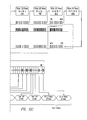
- FIG. 2 illustrates a LED backlight system 50 comprising a graphics processor or video scalar IC 54 , the source of the video signal in a display or TV, an FPGA or microcontroller ( ⁇ C) 53 , a switch-mode power supply (SMAS) 75 , sixteen driver ICs 51 A through 51 P (collectively referred to as driver ICs 51 ), each of driver ICs 51 driving sixteen LED strings 57 A- 57 P through 72 A- 72 P.
- driver IC 51 A drives LED strings 57 A through 57 P
- driver IC 51 B drives LED strings 58 A through 58 P, etc.
- backlight system 50 represents a 256 string LED drive solution.
- driver ICs 51 are controlled by a common SPI bus 52 generated by ⁇ C 53 in response to video information generated by graphics processor or video scalar IC 54 .
- the microcontroller 53 also generates the Vsync and GSC timing signals.
- the PWM brightness data and phase delay may be dynamically adjusted for every channel and LED string uniquely for each and every video frame, so long as the data is written to the driver IC before the next Vsync signal pulse arrives.
- backlighting system 50 facilitates local dimming capability, reduces power consumption, and enhances image contrast, significantly outperforming uniformly illuminated backlit displays.
- system 50 may also dynamically adjust the current in each of the LEDs, but in practice these currents are not changed frequently except during mode changes, e.g. switching between 2D and 3D modes in a HDTV.
- mode changes e.g. switching between 2D and 3D modes in a HDTV.
- the LED currents are doubled, the Vsync frequency is doubled, and the PWM pulse duration is halved when compared to normal 2D display mode.
- the doubling of the frequency is needed to alternatively display the left and right eye information without introducing image flicker.
- the LED currents are not normally adjusted except during calibration at the factory during manufacturing.
- SMPS 75 generates at least two outputs, a regulated 24V supply 74 used to power driver ICs 51 A through 51 P, and the high-voltage +V LED supply 73 , dynamically varied in response to a current sense feedback (CSFB) signal on line 76 A.
- CSFB line 76 A carries the CSFB signal that is generated from CSFB circuitry like that shown in CSFB circuit 5 in system 1 .
- the CSFB signal on line 76 A is connected in daisy chain fashion with the CSFB signal on line 76 B input to driver IC 51 A from driver IC 51 B, which in turn is connected with the CSFB signal on line 76 C from the prior driver IC, and so on.
- Each of driver ICs 51 A- 51 P outputs a CSFB signal representing the lowest current sink voltage of its outputs and of the outputs of all the prior drivers in the daisy chain.
- Each of lines 76 A- 76 P therefore operates at a different voltage, diminishing in value stage by stage as the CSFB signal approaches SMPS 75 .
- the final CSFB signal on line 76 A therefore represents the lowest current sink voltage and likewise corresponds to the highest LED string voltage in the entire system.
- the CSFB signal on line 76 A that is input into SMPS 75 may be a voltage or a control current.
- the CSFB voltage signal can be converted into a current by inserting a transconductance amplifier in the feedback signal path 76 A. This is illustrated in FIG. 2 by transconductance amplifier 77 shown in dashed lines.
- backlight system 50 represents a 256 string LED drive solution.
- the total solution embodied by system 50 utilizes 1,024 LEDs.
- the cost of this would be too high except for the most expensive high-end HDTVs.
- the maximum current for a 16-channel drive IC is 50 mA per channel, such a system would have a total drive current of 51 LED-amps.
- the unit “LED-amps” is the product of the total number of LEDs and the current flowing through each of them, respectively. Since the brightness of an LED is proportional to its current, “LED-amps” is a measure of the luminance, i.e. the total brightness, of a backlight system.)
- the major cause of heating in LED driver ICs is not in the intrinsic operation of the IC, but due to mismatch in the forward voltage of the LED strings being driven.
- a current sink 118 conducting current V LED1 and biased at a voltage V sink1 drives a string of “m” series connected LEDs 101 A through 101 m having a total series voltage of V f1 .
- current sink 119 conducting current and biased at a voltage V sink2 drives a string of “m” series connected LEDs 102 A through 102 m having a total series voltage of V f2 .
- an “n th ” channel with current sink 133 conducting current I LEDn and biased at a voltage V sinkn drives a string of “m” series connected LEDs 117 A through 117 m having a total series voltage of V fn . All “n” strings are powered by a common shared high voltage supply +V LED biased at voltage slightly higher than the highest voltage LED string in the system
- V sink +V LED ⁇ V f
- V 3 ⁇ 1 is the 3-sigma standard deviation of the forward voltage across a single LED and V 3 ⁇ m is the 3-sigma standard deviation of the forward voltage across a string of “m” randomly selected series-connected LEDs. This relationship is shown in FIG. 3B where V 3 ⁇ 1 is assumed to be 0.6V.
- V min Even in the absence of any channel-to-channel mismatch, there is some minimum voltage V min ever-present across all the current sink devices needed to maintain their operation as controlled constant-current devices.
- This minimum voltage similar to the “drop-out” voltage on a linear voltage regulator, is the minimum drain-to-source voltage drop present across the MOSFET and its associated current sensing element within a current sink device below which it can no longer insure that a constant and controlled current will flow in the LED string it drives. With constant improvement, the minimum voltage across a current sink device is now approximately 0.5V.
- a minimum drop of a V min means every current sink device must dissipate at least P sink (min) ⁇ V min ⁇ I LED , and an n-channel driver IC will dissipate “n” times that amount. For example, a 100 mA current through the current sink device will dissipate (100 mA) ⁇ (0.5V) or 50 mW per channel and a sixteen channel LED driver will therefore necessarily dissipate a total power P total of at least 800 mW with no mismatch in the forward voltage V f across the respective LED strings.
- n is the number of integrated channels
- m is the number of series-connected LEDs in each channel
- I LED is the LED current
- V 3 ⁇ 1 is the 3-sigma value for a single LED forward voltage.
- the total power dissipation in a driver IC is the same whether the system includes one LED string conducting 200 mA, two IED strings conducting 100 mA each, or four strings conducting 50 mA each.
- the total power dissipated in the driver IC is solely a function of the sum total of the currents conducted through the IED strings.
- FIG. 3C This relationship is illustrated in FIG. 3C where the columns represent the total driver current I total for a driver IC ranging from 200 mA to 1 A and the rows represent the number of series LEDs “m”. Each square illustrates the statistically average power dissipation for a driver IC with that design combination.
- the lower right hand corner represents the hottest, highest power condition
- designs in the upper left hand corner represent the coolest, lowest power designs.
- Region 159 in FIG. 3C illustrates operating conditions dissipating power less than 1 W, a level easily manageable by printed circuit board (PCB) design to avoid overheating.
- PCB printed circuit board
- a two channel driver carrying 150 mA per string can drive strings of 20 LEDs connected in series without overheating.
- the current can safely be increased to 200 mA per string (or 400 mA in total) if the number of series LEDs is no more than eleven, i.e. m ⁇ 11.
- Region 158 represents poor electro-thermal design choices, leading to spurious or constant overheating problems, long term and short term reliability risks, and even fire hazard.
- Region 156 illustrates operating conditions requiring a package and PCB design capable of dissipating 1.5 W.
- Region 157 illustrates operating conditions requiring a package and PCB design capable of dissipating at least 2 W.
- Such designs require a soldered exposed die pad to conduct heat from the driver IC into the printed circuit board copper traces, and likely require a 4-layer PCB.
- Multi-layer PCBs because of their sandwich of copper conductive traces, electrical vias, and solid copper ground planes, intrinsically carry and redistribute heat effectively compared to thinner lower cost PCBs. In more expensive “high-end” HDTVs for example, the demand for a high resolution backlight system demands a greater number of lower current LED strings to enhance image contrast.
- a 5s16p driver design i.e.
- the information in FIG. 3C is displayed parametrically in a semilog graph in FIG. 3D with the total driver IC power dissipation on the y-axis plotted against the number of series connected LEDs “m” on the x-axis, varied parametrically by the total driver current I total shown by curves 161 through 167 at currents of 200 mA, 250 mA, 300 mA, 400 mA, 500 mA, 600 mA, 800 mA and 1000 mA, respectively.
- the 1 W, 1.5 W and 2 W limits are marked as lines 168 , 169 and 170 to delineate the borders of regions 159 , 156 , 157 , and 158 of table 155 .
- FIG. 3D clearly illustrates that the number of series connected LEDs “m” must be reduced as the current handling capability of the driver IC is increased.
- 600 mA of drive capability limits the maximum number of series connected LEDs to around 11, while at 800 mA, the maximum number of series LEDs is half that amount, i.e. m ⁇ 5.
- FIG. 3D also illustrates that the package power handling demand rises quickly with increasing current.
- a 1 W package is limited to 400 mA or total drive current
- a 1.5 W package is limited to 600 mA
- a 2 W package and PCB design can only safely deliver 800 mA.
- the total per channel current is therefore thermally limited to 50 mA, 75 mA and 100 mA respectively, currents too low to facilitate lower LED count designs—designs where fewer LED strings are driven at higher currents.
- FIG. 4 illustrates a multichip system 200 for driving the LEDs.
- the controller architecture is similar to that contained in driver IC 2 , except that the multi-channel current sink devices, current sensing elements, and voltage protection devices have been removed from a controller IC 202 .
- Controller IC 202 drives multiple discrete transistor components as current sink devices 217 A- 217 n , using multiple discrete passive components 228 A- 228 n to accurately measure current in the current sink devices 217 A- 217 n and in LED strings 203 A- 203 n .
- Additional discrete transistor components 225 A- 225 n are optionally employed to clamp the maximum voltage present across the current sink devices 217 A- 217 n , especially for operation at higher voltages, e.g. over 100V.
- the active current sink device 217 A controlled by IC controller 202 comprises a discrete power MOSFET, specifically a vertical DMOSFET 223 A with an intrinsic drain to body diode 224 A.
- Vertical DMOSFET 223 A cannot be operated near the avalanche voltage of diode 224 A or else hot-carrier damage may result, especially during constant current operation. Typical rated breakdown voltages may vary from 30V to 60V.
- the gate of the DMOSFET 223 A embodying current sink device 217 A is driven by the DRIVE output of controller IC 202 , specifically the output of an amplifier 216 A.
- Bias supply 222 regulates input voltage V IN , e.g. 24V, to a lower voltage Vcc, e.g. 5V. This voltage is then used to power the remaining circuit blocks within IC 202 .
- bias circuit 222 establishes internal reference current Iref used to bias D/A converter 215 A and ultimately set the maximum current in DMOSFET 223 A.
- the precision in Channel-to-channel current matching is set by sense resistor 229 A, and by the voltage offset in amplifiers 219 A and 216 A. Since there are more sources of error in this multichip approach, trimming and the precision of sense resistor 229 A are more stringent than circuits where trimming can be performed in closed loop operation.
- SPI bus interface 204 passes PWM brightness and phase delay signals through registers 209 and 210 , respectively, the respective outputs of which are subsequently processed by timing and control unit 211 to pulse the output of amplifier 216 A, driving the gate of DMOSFET 223 A synchronously with the Vsync and GSC signals.
- discrete transistor component 225 A embodied by a vertical power DMOSFET 226 A with high-voltage drain to body diode 227 A, is typically added to protect the current sink DMOSFET 223 A from damage.
- the gate of DMOSFET 226 A is biased to a fixed voltage, e.g. 12V, and its source is connected in a source-follower configuration to the drain of current sink DMOSFET 223 A and its drain is connected to LED string 203 A.
- a source-follower the maximum voltage on the source of DMOSFET 226 A is limited to a threshold voltage below its gate bias, i.e. to around 10V.
- DMOSFET 226 A can be viewed as a “cascode clamp”. In this way a lower voltage rating device, e.g. 20V, can be used to realize current sink DMOSFET 223 A at a lower cost. Also, since a source-follower operates in its linear region, behaving like a resistor, DMOSFET 226 A dissipates much less power than current sink DMOSFET 223 A.
- the source voltage of “cascode clamp” DMOSFET 226 A is also used as the VSENSE input to controller IC 202 , feeding the respective inputs of a CSFB amplifier 213 A and an LED fault detection comparator 220 A.
- the respective outputs of CSFB amplifier 213 A and LED fault detection comparator 220 A are in turn connected to a CSFB circuit 205 and an LED fault register 207 .
- temperature sense circuit 206 can only detect the temperature of IC 202 , where no power is dissipated. Unfortunately, the significant heat is generated in discrete current sink DMOSFET 223 A, where no temperature sensing is provided. Similarly, the other discrete current sink DMOSFETs 223 B- 223 n likewise have no temperature sensing, and these DMOSFETs could overheat without the system being able to detect or remedy the condition.
- FIG. 5A shows a simplified, functional view of the multi-chip system 200 each channel of the LED drive requires a VSENSE, DRIVE and ISENSE line on controller IC 202 , plus three discrete components 225 A, 217 A and 228 A comprising cascode clamp DMOSFET 226 A, current sink DMOSFET 223 A and precision resistor 229 A.
- FIG. 5B illustrates a multi-chip system 270 that is similar to system 200 but in which an Iprecise circuit 282 A has been added to beneficially eliminate the sense resistor 229 A and the current mismatch and inaccuracy inherent in amplifiers 216 A and 219 A. Even the simplified system 270 does not eliminate the need for two discrete device components 225 A and 217 A per channel and does not reduce the number of pins on IC 271 needed to drive and sense the current and voltage in discrete DMOSFETs 226 A and 223 A.
- one 16-channel controller IC requires 48 discrete components and 48 pins to drive 16 strings of LEDs.
- a single 16 channel IC requires 32 discrete components and still requires 48 pins plus 3 ground pins, i.e. 51 pins just to drive 16 strings of LEDs.
- FIG. 6A illustrates a top view of an expensive, high-pin-count package 301 , containing a die 303 , of the kind that is typically needed to support controller IC 202 .
- package 301 is a 72-pin QFN package comprising 51 output pins and 21 interface and control pins.
- Such a package, 9 mm ⁇ 9 mm in area, requires a substantial amount of plastic mold compound, copper and many gold bond wires, and as such is intrinsically expensive.
- LCD manufacturers use single-layer printed circuit board manufacturing technology, in which case the 0.5 mm pin pitch and leadless construction of the QFN package is too advanced for their board assembly capabilities.
- the customer may demand a leaded package with a minimum pin pitch of 0.8 mm, such as a leaded quad flat package (LQFP).
- a leaded quad flat package LQFP
- the package size swells to 14 mm ⁇ 14 mm and the cost increases accordingly.
- FIG. 6B Aside from the high package expense, the enormous build of material (BOM) component count of a multi-chip LED driver system 350 is shown schematically in FIG. 6B .
- Driver system 350 requires an expensive high-pin-count controller IC 356 , 16 discrete current-sink DMOSFETs 354 , 16 discrete cascode clamp DMOSFETs 353 , a microcontroller 357 and an SMPS module 351 .
- current sink DMOSFETs 354 comprise discrete devices 354 A through 354 Q, each packaged in a low thermal resistance package having a heat tab, such as an SOT223 package. No temperature sensing is available in the discrete current sink devices 354 A through 354 Q.
- cascode clamp DMOSFETs 353 comprise discrete devices 353 A through 353 Q, each packaged in a conventional leaded surface-mount package, such as an SOT23 package.
- each LED string 352 A through 352 Q is connected in series with a corresponding cascode clamp discrete DMOSFET 353 A through 353 Q and a discrete current sink DMOSFET 354 A through 354 Q, respectively.
- LED controller IC 356 connects to the current sink devices 354 through 48 conductive traces 359 , connecting to each source, gate, and drain with electrically separate and distinct conductive traces.
- LED controller 356 utilizes the internal current sensing technique of system 270 , shown in FIG. 5B , and therefore does not require 16 current sensing resistors.
- Multi-chip solutions combining an LED controller with discrete power MOSFETs require high BOM counts and even higher-pin-count packaging. Having nearly triple the pin count of fully integrated LED drivers, a sixteen channel solution can require 33 to 49 components and a 72 pin package as large as 14 mm ⁇ 14 mm. Moreover, discrete MOSFETs offer no thermal sensing or protection against overheating.
- This disclosure describes methods and apparatus to drive multiple strings of series-connected LEDs for backlighting, display and lighting applications implemented in a manner to avoid and to protect against overheating.
- a LED driver according to this invention is a distributed system, one lacking a central control unit.
- an interface IC translates information obtained from the host ⁇ C into a simple serial communications protocol, sending instructions digitally to any number of intelligent LED driver “satellite” ICs connected to the serial bus.
- the serial bus uses a protocol containing parameters specific to LED lighting, and is referred to herein as a Serial Lighting Interface (SLI) bus.
- SLI Serial Lighting Interface
- the SLI bus is connected in “daisy-chain fashion” back to the interface IC so that fault conditions such as an open LED, a shorted LED, or an over-temperature fault occurring in any of the driver ICs can be communicated back to the interface IC and ultimately to the host ⁇ C.
- Each driver IC in response to its SLI bus digital instructions, performs all the necessary LED driver functions such as dynamic precision LED current control, PWM brightness control, phase delay, and fault detection. These functions are performed locally, in the LED driver IC, without the assistance of the interface IC.
- Each LED driver IC also includes an analog current sense feedback (CSFB) input and output signal, connected in a daisy chain with the other driver ICs and with the interface IC to provide feedback to the high-voltage switch-mode power supply (SMPS), dynamically regulating the voltage powering the LED strings.
- CSFB analog current sense feedback
- SMPS switch-mode power supply
- the interface IC supplies a reference voltage to all the LED-driver ICs needed to insure good current matching, generates Vsync and grey scale clock GSC pulses to synchronize their operation, and monitors every LED driver IC for potential faults.
- the interface IC also facilitates voltage-to-current translation of the CSFB signal into an ICSFB signal using an on-chip operational transconductance amplifier (OTA).
- OTA operational transconductance amplifier
- FIG. 1 is a circuit diagram of a prior-art multi-channel LED driver IC for LCD backlighting comprising monolithically integrated current sinks
- FIG. 2 is a circuit diagram of a prior-art multi-channel LED drive system for LCD backlighting using monolithically integrated current sinks
- FIG. 3A is a circuit diagram of an equivalent circuit containing a series-parallel network of LEDs.
- FIG. 3B is a graph showing the standard deviation in forward-voltage as a function of number of series connected LEDs “m”.
- FIG. 3C is a table showing power dissipation as a function of number of channels “n” and number of series connected LEDs “m”.
- FIG. 3D is a graph showing total power dissipation as a function of the number of series connected LEDs “m” for several values of channel current.
- FIG. 4 is a circuit diagram of a prior-art multi-channel LED drive system for LCD backlighting using discrete DMOSFETs as integrated current sinks and protective voltage clamps.
- FIG. 5A is a simplified circuit diagram of the prior-art multi-channel LED drive system shown in FIG. 4 , containing a sense resistor and sense amplifier.
- FIG. 5B is a simplified circuit diagram of the prior-art multi-channel LED drive system shown in FIG. 4 , except that the circuit contains integrated “Iprecise” current mirror sensing.
- FIG. 6A is a top view of a package of the kind typically needed to support the controller IC shown in FIG. 4
- FIG. 6B is a diagram illustrating the number of components required for a 16-channel LED drive system according to the prior art.
- FIG. 7 is a circuit diagram of a cascode-clamped dual-channel LED driver with an integral temperature protection flag.
- FIG. 8 is a schematic diagram illustrating reduced build-of-materials (BOM) achieved using an LED driver comprising a dual-channel MOSFET array with cascode clamp and integral temperature protection.
- FIG. 9 is a schematic diagram of a cascode-clamped intelligent LED driver IC with serial bus control.
- FIG. 10 is a schematic diagram of a multi-channel LED backlight system using intelligent LED drivers with cascode-clamp and a serial lighting interface (SLI) bus shift register.
- SLI serial lighting interface
- FIG. 11 is a simplified schematic circuit diagram of the system shown in FIG. 10 , illustrating the significantly reduced build-of-materials (BOM) realized using cascode-clamped intelligent LED driver ICs with SLI bus control and eliminating a high pin-count interface IC.
- BOM build-of-materials
- FIG. 12 is a schematic circuit diagram of a dual-channel high-voltage intelligent LED driver IC with a SLI bus shift register.
- FIG. 13 is a schematic circuit diagram illustrating the significantly reduced build-of-materials (BOM) achieved using high-voltage intelligent LED driver ICs without cascode-clamp MOSFET and with SLI bus control.
- FIG. 14 is a schematic block diagram illustrating an intelligent LED driver with an SLI bus, a digital control and timing (DC&T) circuit and an analog control and sensing (AC&S) circuit.
- DC&T digital control and timing
- AC&S analog control and sensing
- FIG. 15 is a timing diagram for an SLI bus controlling multiple LED driver IC.s
- FIG. 16 illustrates a schematic circuit diagram of an embodiment of an I-Precise current sense and gate driver.
- FIG. 17A is a schematic circuit diagram an I-precise gate driver circuit allowing Dot Correction and comprising an integral N-channel current mirror D/A converter.
- FIG. 17B is a schematic circuit diagram of an I-precise gate drive circuit allowing Dot correction and comprising a current source D/A converter.
- FIG. 17C is a schematic circuit diagram of an I-precise gate drive circuit allowing Dot correction and comprising a current sink D/A converter.
- FIG. 17D is a schematic circuit diagram of an I-precise gate drive circuit allowing Dot correction and comprising a P-channel D/A converter.
- FIG. 18 is a schematic circuit diagram of an LED fault detection circuit and a fault latch circuit.
- FIG. 19A is a schematic circuit diagram of a reference current source.
- FIG. 19B is a schematic circuit diagram of a trimming circuit for the current reference circuit shown in FIG. 19A .
- FIG. 20A is a schematic circuit diagram of an analog current sense feedback (CSFB) circuit.
- CSFB analog current sense feedback
- FIG. 20B is a schematic circuit diagram of a multi-input operational amplifier for the CSFB circuit shown in FIG. 20A .
- FIG. 21 is a schematic circuit diagram of a four-channel LED driver IC.
- FIG. 22 is a diagram of the serial lighting interface (SLI) bus shift register in the LED driver IC shown in FIG. 21 .
- SLI serial lighting interface
- FIG. 7 is a circuit diagram of a DMOSFET array 376 formed within a dual-channel driver 375 in accordance with the invention.
- Array 376 includes two high-voltage N-channel cascode clamp DMOSFETs 377 A and 378 B with corresponding 150V junction diodes 378 A and 378 B, two N-channel current sink DMOSFETs 379 A and 379 B with corresponding 20V or 30V junction diodes 380 A and 380 B, and an integral temperature protection flag circuit 381 .
- cascode clamp DMOSFET 377 A is connected in series with current sink DMOSFET 379 A.
- cascode clamp DMOSFET 377 B is connected in series with current sink DMOSFET 379 B.
- the overall cost per LED channel can be reduced.
- the number of devices and integrated channels must be chosen so as to avoid overheating the IC package 375 at the specified LED current and also to avoid requiring expensive high-pin packages. So long as the cost savings realized by eliminating a number of discrete packages is greater than the additional cost incurred by using one multi-pin package, then an overall cost savings can be achieved.
- each of the current sink DMOSFETs 379 A and 379 B could be fabricated in an SOP23 package, and each of the cascode clamp DMOSFETs 377 A and 378 B could be fabricated in an SOP 223 package.
- all four DMOSFETs 379 A, 379 B and 377 A, 377 B could be fabricated in a single SOP16 package.
- One SOP16 package is cheaper than two SOT23 packages and two SOT223 packages.
- an SOT23 package costs “x”, then its heat tabbed counterpart, the SOT223 package, costs 1.7 ⁇ because of the added material and manufacturing complexity in forming the heat tab.
- the silicon costs of the integrated solution can be equal to or lower than those of discrete packages.
- Integrated implementations also improve active area utilization by eliminating the silicon die overhead costs associated with the high-voltage termination and scribe street in small area discrete devices.
- the cascode clamp DMOSFETs 377 A and 377 B limit the maximum voltage impressed on the drains of the current sink DMOSFETs 379 A and 379 B.
- V clamp V S ⁇ V G ⁇ V t
- the maximum cascode clamp voltage is, as shown, approximately a threshold voltage lower than the gate bias of cascode clamp DMOSFETs 377 A and 377 B.
- a 2V threshold and a 12V gate bias for DMOSFETs 377 A and 377 B provides a maximum clamp voltage of 10V, far below the onset of impact ionization and hot carrier generation in current sink DMOSFETs 379 A and 379 B.
- All four DMOSFETs 377 A, 377 B and 379 A, 379 B are fabricated by known techniques so as to be electrically isolated from the enclosing grounded P-type substrate of the array 376 .
- DMOSFETs 377 A, 377 B and 379 A, 379 B can “float” to potentials above ground.
- the source, gate, and drain terminals of current sink DMOSFETs 379 A and 379 B are all individually accessible through their corresponding ISENSE, DRIVE, and VSENSE pins to facilitate interconnection with any LED backlight controller IC.
- Access to the ISENSE1 and ISENSE2 pins of current sink DMOSFETs 379 A and 379 B supports both resistor-based current sensing or Iprecise current-mirror based sensing and feedback control methods described above. Access to the VSENSE1 and VSENSE2 pins of current sink DMOSFETs 379 A and 379 B facilitates enhanced system safety through shorted LED detection.
- the level of integration represented in package 375 is significant because it not only reduces BOM component counts and associated costs, but it facilitates the inclusion of the integral temperature protection flag circuit 381 , a feature not possible using discrete devices. Furthermore, package 375 also facilitates the integration of ESD protection devices 382 A, 382 B and 382 C, which is not possible in discrete DMOSFETs.
- This dual-channel DMOSFET array can be used to implement a multi-chip backlighting system 400 , shown in FIG. 8 , wherein each of the drivers 403 is similar to the driver 375 shown in FIG. 7 and contains a DMOSFET array similar to array 376 .
- An LED controller 405 drives the LED drivers 403 to control the current in LED strings 402 in response to instructions from a microcontroller ( ⁇ C) 406 .
- ⁇ C microcontroller
- a first driver IC 403 A controls the current in an LED string 402 A according to instructions received through a control line 404 A comprising the aforementioned ISENSE1, DRIVE1, and VSENSE1 pins for driver IC 403 A.
- driver IC 403 A also controls the current in an LED string 402 B through according to instructions received through a control line 404 B comprising the aforementioned ISENSE2, DRIVE2, and VSENSE2 named pins for driver IC 403 A.
- control line 404 B comprising the aforementioned ISENSE2, DRIVE2, and VSENSE2 named pins for driver IC 403 A.
- six control and sense lines interconnect driver IC 403 A to LED controller IC 405 .
- a second driver IC 403 B controls the current in an LED string 402 C according to instructions received through a control line 404 C comprising the aforementioned ISENSE1, DRIVE1, and VSENSE1 pins for driver IC 403 B.
- the driver IC 403 B also controls the current in LED string 402 D according to instructions received through a control line 404 D comprising the aforementioned ISENSE2, DRIVE2, and VSENSE2 named pins for driver IC 403 B.
- six control and sense lines are required to interconnect driver IC 403 B to LED controller IC 405 .
- driver IC 403 C drives LED strings 402 E and 402 F in response to instructions received through control lines 404 E and 404 F
- driver IC 403 D drives LED strings 402 G and 402 H in response to instructions received through control lines 404 G and 404 H, and so on.
- each of control lines 404 A- 404 Q includes three control and sense lines for a total of 48 signal paths which are physically embodied as 48 PC board conductive traces 408 .
- controller IC 405 Because each of driver ICs 403 A- 403 H passes distinct VSENSE signals back to controller IC 405 , controller IC 405 has the necessary information to determine which of the LED strings 402 A- 402 Q has the highest series forward voltage and to provide feedback signal 409 to SMPS unit 401 to dynamically generate the proper voltage on the +V LED supply rail.
- the multi-chip backlighting system 400 includes the capability for thermal feedback and temperature protection. Moreover, an over-temperature flag signal is fed back from drivers 403 A- 403 H to microcontroller 406 on a single line 407 , using a digital wire “OR” connection, to facilitate over-temperature shutdown protection capability for system 400 .
- the per-package power dissipation is reduced compared to prior-art multi-channel driver IC 2 , facilitating higher current operation and providing more uniform heating across a printed circuit board to avoid “hot spots” that may be visually obvious in an overlaying LCD screen.
- driver ICs 403 can be used in any size of display to support any number of channels, offering a fully scalable system architecture limited only by the number of channels supported by LED controller 405 .
- driver ICs 403 and system 400 offer distinct advantages over today's prior art systems and conventional architectures, they do not eliminate certain prohibitively high-cost components. In particular, this approach still suffers from high interconnection costs affecting packaging expense and printed circuit board design.
- a sixteen-channel backlighting solution using the dual-channel DMOSFET concept still requires 48 distinct electrical traces 408 on its driver PCB and demands an expensive LED controller 405 packaged in a large area high-pin-count package with over 50 output and ground pins and over 70 pins in total.
- the number of pins required for an array with “n out ” channels, including power and ground pins, is equal to 3+3 ⁇ n out .
- a dual channel device requires 9 pins, leaving seven pins free in a sixteen-pin package.
- a three-channel version requires a total of 12 pins, using up nine pins just for DMOSFET drive and sensing, and leaving only four pills free in an SOP16 package.
- a four-channel version uses essentially every available pin, leaving no possibility for feature expansion.
- the second method completely removing the current sink MOSFETs from the controller IC as exemplified by system 200 in FIG. 4 , dramatically increases system BOM component counts, and forces the controller IC into even higher pin count packages, requiring at least three pins per output channel. Separating the current sink MOSFETs from their analog control circuitry reduces current sink accuracy, sacrifices noise immunity, and greatly complicates digital-to-analog conversion needed for dot correction.
- the invention described herein enables a new cost-efficient and scalable architecture for realizing safe and economically viable LED backlighting systems for large-screen LCDs and TVs with energy efficient local dimming capability.
- the LED drive system, functional partitioning, and architecture disclosed herein completely eliminate the aforementioned problems in cost, functionality and the need for high pin count packages.
- the new architecture is based on certain fundamental premises, including:
- the conventional architecture of FIG. 4 i.e. a centralized controller driving a number of discrete power MOSFETs, fails to meet even one of the above goals, primarily because it requires a central point of control, or “command center”, for all digital and analog information processing. Necessarily, the command center IC must communicate with its ⁇ C host as well as directly sensing and driving every current sink MOSFET. This high degree of component connectivity demands a large number of input and output lines, necessitating high-pin-count packaging.
- LED driver 450 is a dual channel driver comprising integrated current sink DMOSFETs 455 A and 455 B, cascode clamp DMOSFETs 457 A and 457 B with integral high-voltage diodes 458 A and 458 B, I-precise current sensing and gate bias circuits 456 A and 456 B for accurate current control, an analog control and sensing circuit 460 , and a digital control and timing circuit 459 .
- An on-chip bias supply and regulator 462 powers the IC.
- One of the channels includes current sink DMOSFET 455 A, cascode clamp DMOSFET 457 A and I-precise sensing and gate bias circuit 456 A, which together drive an LED string 452 A.
- the other channel includes current sink DMOSFET 455 B, cascode clamp DMOSFET 457 B and I-precise sensing and gate bias circuit 456 B, which together drive an LED string 452 B.
- LED driver 450 provides complete control of two channels of 250 mA LED drive with 150V blocking capability and ⁇ 2% absolute current accuracy, 12 bits of PWM brightness control, 12 bits of PWM phase control, 8 bits of current control, fault detection for LED open and LED short conditions and over-temperature detection, all controlled through a high-speed serial lighting interface (SLI) bus shift register 461 , and synchronized to other drivers by a common Vsync and grey-scale clock (GSC) signal.
- SLI serial lighting interface
- GSC grey-scale clock
- cascode clamp DMOSFETs 457 A and 457 B are rated at 150V blocking capability, although in other embodiments these devices can be sized for operation from 100V to 300V.
- the current rating of 250 mA is set by the power dissipation of the package and the mismatch in forward voltage in the two LED strings 452 A and 452 B.
- LED driver 450 receives a stream of data on its serial input SI pin that is fed into the input of SLI bus shift register 461 .
- the data is clocked at a rate set by a serial clock signal SCK supplied by the interface IC (not shown in FIG. 9 ).
- SCK serial clock signal
- the maximum clock rate for the data depends on the CMOS technology used to implement SLI bus shift register 461 , but operation at 10 MHz is achievable even using 0.5 ⁇ m linewidth processes and wafer fabs.
- SCK serial clock signal
- a Vsync pulse latches the data from the SLI bus shift register 461 into data latches contained within the digital control and timing circuit 459 and into data latches contained within the analog control and sensing circuit 460 , the data latches comprising flip flops or static RAM. Also at the time of the Vsync pulse, any data previously written into the fault latches contained within the analog control and sensing circuit 460 will be copied into the appropriate bits of SLI bus shift register 461 .
- the interface IC When the interface IC resumes sending the serial clock SCK signal, the read and the write bits stored within SLI bus shift register 461 are moved into the next driver IC in the daisy chain.
- the daisy chain forms a loop connecting back to the interface IC. Sending new data into the daisy chain ultimately pushes the existing data residing in the SLI bus shift registers on through the loop and ultimately back to the interface IC.
- the interface IC can communicate with the individual LED driver ICs, setting LED string brightness and timing, and the individual driver ICs can communicate individual fault conditions back to the interface IC.
- Vsync may vary from 60 Hz to 960 Hz with the grey scale clock frequency scaling proportionately, typically 4096 times the Vsync frequency. Since Vsync is slow, under 1 kHz, when compared to the frequency of the SCK signal driving the SLI bus shift registers, the interface IC has the flexibility to modify and resend the data, or query the fault latch multiple times within a given V-sync pulse duration.
- the digital control and timing circuit 459 generates two PWM pulses to toggle the output of I-Precise current sensing and gate bias circuits 456 A and 456 B on and off after the proper phase delay and for the proper pulse width duration, or duty factor D.
- I-Precise current sensing and gate bias circuits 456 A and 456 B sense the current in current sink MOSFETs 455 A and 455 B respectively and provide the proper gate drive voltage to maintain a target current during the time I-precise circuits 456 A and 456 B are enabled by the PWM pulses from digital control and timing circuit 459 . Operation of the I-Precise circuits 456 A and 456 B is thus similar to that of a “strobed” amplifier, being pulsed on and off digitally but providing a control function.
- the peak current is set globally in all the LED drivers by the Vref signal and by the value of Iset resistor 454 .
- the Vref signal is generated by the interface IC.
- the Vref signal may be supplied as an auxiliary output from SMPS 401 in FIG. 8 .
- the specific current in any LED string can be further controlled through the SLI bus shift register by the Dot latch embedded within AC&S 460 using an 8 to 12 bit word that adjusts the current sink DMOSFET's current to a percentage from 0% to 100% of the peak current value.
- precise digital control of the LED current emulating the function of a current mode digital-to-analog converter or “current DAC”, is possible using this architecture.
- this feature can be used for calibrating the backlight brightness, for improving backlight uniformity, or for operating in 3D mode. If the same driver IC is used to drive red, green, and blue LEDs in LED signs and displays, i.e. displays using LEDs but not using an LCD panel, the Dot setting can be used to calibrate the relative brightness of the LEDs to set the sign's proper color balance.
- the current flowing through LED string 452 A is controlled by current sink DMOSFET 455 A and corresponding I-Precise current sensing and gate bias circuit 456 A.
- the current flowing through LED string 452 B is controlled by current sink DMOSFET 455 B and corresponding I-Precise current sensing and gate bias circuit 456 B.
- the maximum voltage impressed upon current sink DMOSFETs 455 A and 455 B is limited by cascode clamp DMOSFETs 457 A and 457 B, respectively.
- bias circuit 462 which in this embodiment is 12V.
- Bias circuit 462 also generates a 5 V Vcc supply voltage to operate its internal circuitry from the 24V VIN input, using a linear voltage regulator and a filter capacitor 453 .
- the drain voltages on current sink DMOSFETs 455 A and 455 B are also monitored by analog control and sensing circuit 460 and compared to an over-voltage value stored in a latch within analog control and sensing circuit 460 .
- the over-voltage value is supplied from SLI bus shift register 461 . If the drain voltages of current sink DMOSFETs 455 A and 455 B are below the programmed values, the LED strings 452 A and 452 B are operating normally. If, however, the drain voltage of either current sink DMOSFET 455 A or current sink DMOSFET 455 B rises about the programmed value, one or more of LED strings 452 A and 452 B is shorted, and a fault is detected and recorded for that specific channel.
- the I-Precise circuit 456 A or the I-Precise circuit 456 B cannot maintain the required current in one of LED strings 452 A or 452 B, i.e. the LED string is operating “undercurrent”, this means that an LED in one of strings 452 A or 452 B has failed open and the circuit continuity has been lost. The corresponding channel is then turned off, its CSFB signal is ignored, and the fault is reported. Sensing this “undercurrent”, can be performed by monitoring the output of the gate buffer devices within I-Precise circuits 456 A and 456 B for saturation. This condition means that the buffer is driving the gate of the corresponding current sink DMOSFET as “full on” as it can. Alternatively, an undercurrent condition can be detected by monitoring the voltage drop across the input terminals of the I-Precise circuits. When the I-Precise input voltage drops too low, the undercurrent condition has occurred, and an open LED fault is indicated.
- analog control and sensing circuit 460 will disable the channel independently and report the fault. Regardless of the nature of a fault, whether a shorted LED, an open LED, or an over-temperature condition, whenever a fault occurs an open drain MOSFET within analog control and sensing circuit 460 will activate and pull the FLT low, signaling to the interface IC and optionally to the host ⁇ C that a fault condition has occurred.
- the FLT pin is a system-interrupt signal informing the system 1 C whenever a fault condition has occurred in one or more of the LED driver ICs.
- the line is held high, i.e. biased to Vcc through a high value resistor.
- the specific LED driver IC pulls the line low by enabling a grounded N-channel MOSFET such as MOSFET 689 in FIG. 14 .
- timing and control circuit 624 within interface IC 601 can query the LED driver ICs through SLI bus interface 623 to ascertain what LED driver IC is experiencing a fault condition and what kind of fault has occurred. Interface IC 601 then communicates this information back to the host microcontroller through the SPI bus interface 622 enabling the system to make decisions as to what action, if any, should be taken in response to the fault occurrence. Since the FLT line employs open drain MOSFETs to actively pull the line low in the event of a fault, in the absence of a fault the line is pulled high by a high-value internal resistor.
- the FLT input to interface IC 601 can be paralleled with the interrupt input pin of the system ⁇ C, in which case any fault generated by the LED driver ICs not only informs interface IC 601 of the fault condition, but can also generate an interrupt signal in the ⁇ C, alerting it to the condition as well.
- Using the FLT line therefore provides an immediate indication of the occurrence of a fault in an LED driver IC while the SLI bus and SPI bus are used to gather additional information before deciding what action to take. In this way, full fault management is enabled without the need for a fully integrated driver IC.
- Analog control and sensing circuit 460 also includes an analog current sense feedback (CSFB) signal, which is equal to the lowest voltage among the drain voltages of the two current sink DMOSFETs 455 A and 455 B and the voltage at the CSFBI input pin.
- CSFB analog current sense feedback
- the CSFB signal is passed to the CSFBO output pin. In this way, the lowest current sink voltage in LED strings 452 A and 452 B drop is passed to the input of the next LED driver and ultimately back to the system SMPS to power the +V LED supply rail.
- LED driver 450 with integral dimming and fault detection capability is realized without the need for a central controller IC.
- FIGS. 10A and 10B illustrate a distributed multi-channel LED backlight driver system 500 in accordance with this invention. Shown are an interface IC 501 for driving a series of LED driver ICs 503 A- 503 H powered by a common switch-mode power supply (SMPS) 508 . Although only LED driver ICs 503 A and 503 H are shown in FIG. 10A , it is understood that similar driver ICs 503 B- 503 G are located between driver ICs 503 A and 503 H. Each of LED driver ICs 503 A- 503 H has integral dimming and fault detection capability and is similar to the LED driver 450 shown in FIG. 9 .
- SMPS switch-mode power supply
- Five common signal lines 507 comprising three digital clock lines (SCK, GSC and Vsync), one digital fault line (FLT), and one analog reference voltage line (Vref) connect interface IC 501 to LED driver ICs 503 A- 503 H.
- a timing and control unit 524 generates the Vsync and GSC signals in synchronism with data from a host ⁇ C (not shown), received through SPI bus interface 522 .
- Timing and control unit 524 also monitors the fault interrupt line FLT to immediately detect a potential problem in one of LED strings 506 A- 506 Q.
- a voltage reference source 525 provides a voltage reference to the system globally over the Vref line in order to insure good channel-to-channel current matching.
- a bias supply unit 526 powers interface IC 501 through a V IN line that is connected to a fixed +24V supply rail 510 supplied by SMPS 508 .
- the +24V supply rail 510 is also used to power LED driver ICs 503 A- 503 H.
- each LED driver IC 503 A- 503 H comprises two channels of high-voltage current control circuitry.
- LED driver IC 503 A includes cascode clamp DMOSFETs 520 A and 520 B, current sink DMOSFETs 519 A and 519 B, I-Precise gate driver circuits 518 A and 518 B, digital control and timing circuit 515 A, analog control and sensing circuit 516 A and serial SLI bus shift register 514 A.
- LED driver IC 503 H includes cascode clamp DMOSFETs 520 P and 520 QB, current sink DMOSFETs 519 P and 519 Q, I-Precise gate driver circuits 518 P and 518 Q, digital control and timing circuit 515 H, analog control and sensing circuits 516 H and serial SLI bus shift register 514 H.
- An SLI bus 513 comprising signal lines 513 A- 513 I, links the LED driver ICs 503 A- 503 H together into a daisy chain in the embodiment shown in FIGS. 10A and 10B .
- the serial output terminal of SLI unit 523 (the SO pin of interface IC 501 ) connects via a signal line 513 A to the SI input of LED driver IC 503 A, the SO output of LED driver IC 503 A connects via a signal line 513 B to the SI input of LED driver IC 503 B (not shown), and so on.
- the SO output of LED driver IC 503 H connects via a signal line 513 I to the serial input terminal of SLI unit 523 (the SI pin of interface IC 501 ).
- SLI bus 513 forms a complete loop, emanating from the interface IC 501 , running through each of LED driver ICs 503 A- 503 H and back to interface IC 501 .
- shifting data out of the SO pin of interface IC 501 concurrently returns a bit string of equal length back into the SI pin of interface IC 501 .
- SLI unit 523 also generates the SLI bus clock signal SCK as required. Because the LED driver ICs 503 A- 503 H have no addresses, the number of bits clocked through the SLI bus must correspond to the number of devices being driven, with one bit advanced for each SCK clock pulse. The number of devices being driven may be adjusted through software programming the data exchange in SPI interface 522 , or by hardware modification to interface IC 501 . In this manner the number of channels within system 500 can be varied flexibly to match the size of the display.
- CSFB line 512 H connects the CSFBO output pin of LED driver IC 503 H to the CSFBI input pin of LED driver IC 503 G and so on.
- CSFB line 512 A connects the CSFBO output pin of LED driver IC 503 A to the CSFBI input pin of interface IC 501 .
- the voltage level of the CSFB signal drops whenever it passes through one of LED driver ICs 503 A- 503 H driving an associated LED string 506 A- 506 Q that has a higher forward-voltage Vf than the LED strings associated with the LED drivers that the CSFB signal has previously passed through. Since LED driver ICs 503 A- 503 H are arranged in a daisy chain, the CSFB signal ratchets down as it passes from the LED driver IC 503 H to the LED driver IC 503 A.
- the CSFB signal in the final CSFB line 512 A represents the forward-voltage Vf of the LED string 506 A- 506 Q having in highest Vf in the entire LED array.
- Operational transconductance amplifier (OTA) 527 converts the final CSFB signal in CSFB line 512 A into a current feedback signal ICSFB 511 , driving the voltage +V LED on line 509 at the output of SMPS 508 to the optimum voltage for flicker free lighting without excess power dissipation.
- CSFB lines 512 A- 512 I are sometimes referred to herein collectively as CSFB line 512 .
- the resulting system shown in the simplified schematic diagram of FIG. 11 achieves independent control and constant current drive of 16 LED strings 506 A- 506 Q using only eight small LED driver ICs 503 A through 503 H, all controlled by interface IC 501 through SLI bus 513 (including signal lines 513 A- 513 I) in response to a host ⁇ C 551 and a scalar IC 552 .
- Only two analog signals are present in the system, a common reference voltage Vref on line 553 , and the ICSFB signal 511 that controls the SMPS 508 to produce the +V LED output on line 509 .
- the ICSFB signal 511 is generated in the interface IC 501 from the CSFB signals on lines 512 A- 512 H. With few analog signals and no discrete DMOSFETs with high impedance inputs, the LED driver system 500 is relatively immune to noise.
- the LED driver system 500 can be fabricated using only nine SOP16 IC packages (one interface IC and eight LED driver ICs) to drive 16 LED strings. Compared to the multi-chip LED driver system 350 of FIG. 6B , which uses 32 discrete MOSFETs and a 72 pin controller IC, the cost of fabrication is greatly reduced by the new architecture. With significantly fewer components, system reliability is also enhanced. System 500 is also easy to deploy since the proprietary SLI bus protocol is used only between interface IC 501 and the satellite LED drivers 503 A through 503 H. The ⁇ C 551 communicates with the interface IC 501 and the scalar IC 552 via the SPI bus.
- An LED driver 580 shown in FIG. 12 is similar to LED driver 450 shown in FIG. 9 , except the cascode clamp DMOSFETs 457 A and 457 B have been removed. As a result, the current sink DMOSFETs 587 A and 587 B must survive the full operating voltage specification of the product. Without the cascode clamp DMOSFETs, the gate oxide rating of the current sink DMOSFETs 587 A and 587 B can typically be lowered to 7V, and the need for the +24V rails to power VIN is largely ameliorated. Instead, a bias circuit 584 requires only Vcc as its input, where Vcc is preferably 5V, a supply voltage convenient for powering precision analog circuitry while still supporting modest levels of digital circuitry using small-size logic gates.
- LED driver 580 is formed in an IC 581 and has two channels controlling the currents through LED strings 583 A and 583 B, respectively.
- the LED driver 580 includes I-Precise gate driver circuits 586 A and 586 B, a digital timing and control circuit 589 , an analog control and sensing circuit 585 and an SLI bus shift register 690 , arranged in the same manner as the corresponding components of LED driver 450 in FIG. 9 .
- FIG. 13 illustrates an LED driver system 600 that is somewhat similar to the system 500 shown in FIG. 10 .
- Corresponding components are numbered “6XX” instead of “5XX” in FIG. 13 .
- the voltage +V LED for LED strings 606 A- 606 Q is supplied by a switch-mode power supply (SMPS) 608 , which is controlled by an interface IC 601 in response to signals from LED driver ICs 603 A- 603 H.
- SMPS switch-mode power supply
- each of LED driver ICs 603 A- 603 H is similar to LED driver IC 581 , shown in FIG. 12 ., i.e., driver ICs 603 A- 603 H do not contain cascode clamp DMOSFETs.
- interface IC 601 can perform the 24V to 5V voltage conversion and distribute its 5V supply rail, i.e. Vcc, to LED driver ICs 603 A- 603 H.
- bias units 617 A- 617 H can be made smaller and the external filter capacitor (i.e., capacitors 504 A- 504 H in FIG. 10 ) can be eliminated, saving one package pin.
- serial lighting interface uses a serial communications method comprising a clocked shift register with a serial input and output, and a clock to control the timing and rate of data transfer.
- FIG. 14 The operation of the SLI bus is illustrated in FIG. 14 , which also provides greater detail of the construction and operation of exemplary embodiments of SLI bus shift register 514 A, digital control and timing (DC&T) circuit 515 A and analog control and sensing (AC&S) circuit 516 A shown in FIG. 10 .
- DC&T digital control and timing
- AC&S analog control and sensing circuit 516 A shown in FIG. 10 .
- similar circuitry is used for SLI bus shift registers 514 B- 514 H, digital control and timing circuits 515 B- 515 H and analog control and sensing circuits 516 B- 516 H shown in FIG. 10 and could also be used for SLI bus shift registers 614 A- 614 H, digital control and timing circuits 615 A- 615 A and analog control and sensing circuits 616 A- 616 H shown in FIG. 13 .
- FIG. 14 shows a dual channel LED driver IC, comprising current sink DMOSFETs 519 A and 519 B and I-Precise gate driver circuits 518 A and 518 B, but LED driver ICs controlling a different number of channels may be implemented in a similar fashion.
- SLI bus shift register 514 A is connected to DC&T circuit 514 A by several parallel data busses, typically 12 bits wide, and also connected to AC&S circuit 516 A by a variety a parallel data busses ranging from 4 bits to 12 bits wide.
- the outputs of DC&T circuit 515 A digitally toggle I-Precise gate driver circuits 518 A and 518 B and current sink DMOSFETs 519 A and 519 B on and off with precise timing synchronized by the Vsync and grey scale clock (GSK) signals.
- the current sink DMOSFETs 519 A and 519 B control the current in two strings of LEDs (not shown) in response to analog signals from AC&S circuit 516 A, which control the I-Precise circuits 518 A and 518 B and hence the gate drive signals for current sink DMOSFETs 519 A and 519 B.
- the gate drive signals are analog, and an amplifier with feedback is used to insure that the current in each of current sink DMOSFETs 519 A and 519 B is a fixed multiple of reference currents Iref A and Iref B , respectively, which are also supplied by AC&T circuit 516 A. Further description of current sink control is detailed later in this disclosure.
- FIG. 14 illustrates only current sink MOSFETs 519 A and 519 B
- the circuitry shown is compatible with either the cascode clamped LED driver 450 shown in FIG. 9 or the high voltage LED driver 581 shown in FIG. 12 .
- two high-voltage N-channel DMOSFETs would be connected in series with current sink DMOSFETs 519 A and 519 B, with the source terminals of the high-voltage N-channel DMOSFETs tied to the drain terminals of the current sink DMOSFETs 519 A and 519 B, and with the drain terminals of the high-voltage N-channel DMOSFETs tied to the anodes of the respective LED strings being driven.
- data is clocked into SLI bus shift register 514 A through the serial input pin SI at a the rate of the SCK clock signal.
- This includes 12 bit PWM on time data into registers 657 A and 657 B for channel A and channel B, 12 bit phase delay data into registers 658 A and 6588 for channel A and channel B, 12 bit “dot” current data into registers 659 A and 659 B for channel A and channel B, along with 12 bits of fault information, comprising 8 bits into fault settings register 671 and 4 bits into fault status register 672 .
- Data within these registers are clocked out of the SO pin as new data is clocked in. Suspending the SCK signal holds data statically within the shift registers.
- the terms “channel A” and “channel B” are arbitrary and are only used to identify the outputs and their corresponding data in the SLI data stream
- the channel remains enabled and conducting for the duration of the number of pulses stored in D latch 681 A and 681 B. Thereafter, the outputs are toggled off and wait for the next Vsync pulse to repeat the process.
- DC&T circuit 652 therefore synthesizes two PWM pulses to the gates of DMOSFETs 519 A and 519 B in accordance with the data in SLI bus shift register 514 A.
- the data stored in Dot A and Dot B registers 659 A and 659 B is copied into D/A converters 683 A and 683 B, setting the current in DMOSFETs 519 A and 519 B.
- the D/A converters 683 A and 683 B are discrete circuits that provide a precise fraction of Iref to set the currents in the associated LED strings.
- DMOSFETs 519 A and 519 B have gate widths divided into various sections using binary weighting, and the proper combination of these gate sections is charged to set the fraction of the maximum current desired.
- the reference current Iref that represents the maximum channel current, is set by Rset resistor 654 and the Vref input to a reference current source 687 .
- the fault detection circuitry includes LED fault detection circuit 685 , which compares the source voltages of current sink MOSFETs 519 A and 519 B against the value stored in fault latch circuit 684 .
- the data in fault latch circuit 684 is copied from the fault settings register 671 at each Vsync pulse.
- Temperature detection circuit 686 monitors the temperature of the LED driver IC 503 A, in which the circuitry showing FIG. 14 is included. Detection of a fault immediately triggers open drain fault flag MOSFET 689 to turn on and pull the FLT line low, generating an interrupt.
- the data in fault latch circuit 684 is written into the fault status register 672 on the following Vsync pulse.
- a serial data bus is used to control the current, the timing of LED turn-on, and the duration of LED illumination of a number of LED strings, as well as to detect and report the occurrence of fault conditions in the LED strings.
- the SLI bus protocol is flexible, requiring only that the data sent through the SLI bus shift register 514 A matches the hardware being controlled, specifically that the number of bits sent per driver IC matches the bits required by each driver IC, and that the total number of bits sent for one Vsync period matches the number of bits sent per driver IC times the number of driver IC.
- the protocol including dot correction, fault setting and fault reporting comprises 88 bits per dual channel driver IC, i.e. 44 bits per channel or LED string.
- Height dual-channel driver ICs, controlling sixteen strings of LEDs are connected into a single SLI bus loop, the total number of bits shifted out of the interface IC and through the SLI bus during each Vsync period is 8 times 88 or 704 bits, less than a kilo-bit. If the SLI bus is clocked at 10 MHz, the entire data stream can be clocked through every driver IC and to every channel in 70.4 microseconds or 4.4 microseconds per channel.
- the serial data bus communicates at “electronic” data rates, i.e. using MHz clocks and Mbits-per-second data rates
- the Vsync, or “frame” rate used to control changing the image on the LCD display panel occurs at a much slower pace, because the human eye cannot perceive changing images quickly.
- the frame rate is both the rate that the image is “written” into the liquid crystal display and the rate that the LED backlight is updated.
- most people are unaware of flicker at 60 Hz frame rates, i.e. sixty image frames per second, in A versus B comparisons, to many people 120 Hz TV images appear more “clear” than 60 Hz TV images, but only using direct comparisons.
- Vsync rates e.g. 240 Hz and up, only “garners” and video display “experts” claim to see any improvement, mostly manifest as reduced motion blur. It is the large ratio between electronic data rates and the relatively slow video frame rate that makes serial bus communication to the backlight LED drivers possible.
- each Vsync period consumes 16.7 milliseconds, orders-of-magnitude longer than the time needed to send all the data to all the driver-ICs.
- each Vsync period consumes 1.04 milliseconds, meaning up to 236 channels can be controlled in real time. This number of channel s greatly exceeds the driver requirements for even the largest HDTVs.
- the 88-bit per dual-channel “fat” protocol used in the SLI bus shift register 514 A of FIG. 14 enables the interface IC to write or read all the data in every register of every channel once during every Vsync period. If a reduced data protocol is used, i.e. a protocol requiring fewer bits per channel, sending data to every channel takes even less time. Since the fat protocol has no timing limitations because of the relatively slow Vsync refresh rate, there is no data rate benefit. Using fewer bits in the serial communication protocol does however reduce the size of the digital shift registers and data latches in the driver ICs, reducing chip area and lowering overall system cost.
- an alternative data protocol for an SLI bus using 64 bits rather than 88-bits is shown in system 700 of FIG. 15 .
- the protocol still uses 12 bits for PWM brightness duty factor, 12 bits for phase delay, 8 bits for fault setting, and 4 bits for fault status, but it omits the 12-bit Dot correction data.
- individual channel current setting and brightness calibration of each LED string is not available in this implementation.
- adjusting the value of Vref affects the value of the reference current Iref produced by reference current source 687 . If the reference voltage Vref is shared by all of the driver ICs, adjusting Vref will uniformly affect every driver IC and consequently the panel's overall brightness, independent of the PWM dimming control.
- system 700 illustrates SLI bus data communication from a common system interface IC 702 to a serially-connected string of eight driver ICs 701 A through 701 H.
- the SLI-bus serial output SO of interface IC 702 generates a sequence of pulses and feeds those pulses to the input pin of driver IC 701 A synchronized to the clock pulses on serial clock pin SC.
- the SLI bus serial output of driver IC 701 A in turn sends its internal shift register data out of its SO pin and into the SI input pin of driver IC 701 B.
- the SO output of driver IC 701 B connects to the input pin of driver IC 701 C and so on, collectively forming a “digital” daisy chain.
- the last driver in the chain 701 H sends its SLI bus data from its SO pin back to the SI pin of interface IC 702 to complete the loop.
- interface IC 702 sends data out of its SO pin in response to instructions it receives on its SPI bus interface to the system's scalar or video IC.
- the data for every driver IC and LED string is clocked from the SO output of interface IC 702 to every driver IC 701 A through 701 H in sequence. All data must be sent to all driver ICs within one single Vsync period. Because the SLI bus is a serial protocol, the first data sent out from interface IC 702 represents the bits used to control driver IC 701 H. After 64 clock pulses, the data destined for driver IC 701 H is present in the SLI bus shift register of driver IC 701 A.
- Interface IC 702 then outputs the data for driver IC 701 G on its SO pin synchronized to another 64 pulses on the SC clock pin. During these 64 clock pulses, the data intended for driver IC 701 H moves from the SLI bus shift register within driver IC 701 A temporarily into the SLI bus shift register within driver IC 701 B. This process is repeated until at last, the data for driver IC 701 A is output on the SO pin of interface IC 702 synchronized to the last 64 pulses on the SC clock.
- the data for driver IC 701 A is output from the SO pin and loaded into the SLI bus shift register within driver IC 701 A
- the data for driver IC 701 B moves from the SLI bus shift register within driver IC 701 A and into the SLI bus shift register within driver IC 701 B, and so on.
- the data for driver 701 H moves from the SLI bus shift register within driver IC 701 G into the SLI bus shift register within driver IC 701 H. Therefore, after 8 ⁇ 64 clock pulses, or 512 pulses on the SC pin, all of the data has been loaded into the SLI bus shift registers of the corresponding driver ICs. Nonetheless, this data is not yet controlling the operation of the LED strings.
- the LED strings will be controlled according to the data received prior to the last Vsync pulse. All the data sent from the interface IC to the LED driver ICs can be sent within a single Vsync clock cycle and takes effect on the next Vsync clock pulse. At the same time that data is being shifted from the interface IC into the LED driver ICs, fault-reporting data within the driver ICs is shifted back into the interface IC.
- the SLI bus data communication timing and clocking is asynchronous with the system's Vsync period and the Vsync pulse that begins each Vsync period. That is to say, data from interface IC 702 may be sent faster or slower through the SLI bus to the driver ICs 701 A- 701 H without the viewer of the display being aware of the ongoing multichip interaction or the changing LED settings until the next Vsync pulse comes along.
- the only timing requirement is that interface IC 702 is able to receive its instructions from the video controller or scalar IC via its SPI bus input, interpret those instructions and output the channel specific information on the SO pin of its SLI bus for every driver IC within a single Vsync period. As described earlier, since the time needed to receive such instructions is much shorter than the Vsync period, this timing requirement imposes no limitations in the operation of the display.
- FIG. 15 also illustrates that the Fault Set data register may comprise various kinds of data, including data for adjusting the voltage used to detect a shorted LED (the SLED set code), setting a period of time used to ignore the fault output from a shorted LED detect (shorted LED fault blanking), setting a period of time used to ignore the fault output from open LED detect (open LED fault blanking), and clearing previously reported open and shorted LED fault registers (open CLR and short CLR).
- the SLI bus protocol is not limited to implementing specific fault related functions or features.
- System 700 also illustrates the fault read back capability of implementing the SLI bus as a loop by connecting the SO output of the last driver IC in the daisy chain (driver IC 701 H) to the SI input of interface IC 702 . While writing data from interface IC 702 into driver ICs 701 A- 701 H, the data residing within the SLI bus shift registers advances through the daisy chain with each SC clock pulse.
- the data within the SLI bus shift registers includes fault detection data written by one of driver ICs 701 A- 701 H, then clocking that data through the loop and back into interface IC 702 facilitates a means by which a specific fault condition in one of the driver ICs 701 A- 701 H can be reported back to the interface IC 702 and through the SPI bus to other components of the system.
- What interface IC 702 does with the fault information depends on its design and is not limited by the SLI bus protocol or hardware.
- FIGS. 15-20 show detailed circuit diagrams of some of the functional units that are included in digital control and timing (DC&T) circuit 615 A and analog control and sensing (AC&S) circuit 616 A, shown in FIG. 14 . While the detailed circuit diagrams illustrate enabling embodiments of the invention, they do not represent exclusive implementations of these circuits.
- DC&T digital control and timing
- AC&S analog control and sensing
- Latch & Counter A blocks 680 A and 680 B comprise a assembly of flip-flops, logic gates and latches well known to those skilled in the art and therefore will not be described in detail.
- the I-Precise gate driver circuits use feedback to match LED currents I LEDA and I LEDB in the LED strings to a fixed multiple of a common reference current Iref supplied by reference current source 687 . In this way, current matching and the absolute value of LED current can be held to an accuracy of ⁇ 2% without the need for excessive trimming or numerous and costly discrete precision components.
- FIG. 16 illustrates an I-Precise gate driver circuit 656 A.
- the gate drive of current sink DMOSFET 519 A is controlled by an operational amplifier 752 supplying the precise gate voltage needed to reach a specific LED current in LED string 506 A.
- a current mirror comprising a pair of N-channel MOSFETs 755 and 754 , identical in cellular design to minimize device mismatch, controls the current in the LED string 506 A.
- MOSFET 754 used as the reference for the mirror and designed to carry an input current Iref supplied by reference current source 687 in the range of microamperes to milliamperes, has a gate width W.
- the mirror MOSFET 755 has a gate-width “n” times larger than W, i.e.
- MOSFET 754 is connected in a totem pole arrangement with an N-channel MOSFET 753 , and the gate terminals of MOSFETS 753 , 754 and 755 are connected together and to the drain of MOSFET 753 .
- the common gate voltage of MOSFETS 753 , 754 and 755 is designated V GS (ref).
- a gate-to-source voltage Vgs(ref) is developed across current mirror MOSFETs 754 and 755 , i.e. both mirror MOSFETs 754 and 755 have the same gate bias.
- the gate drive and drain-to-source voltages of MOSFETs 754 and 755 should be nearly identical.
- operational amplifier 752 has its inputs connected to the respective drain terminals of the current mirror MOSFETs 754 and 755 and has its output terminal connected to the gate terminal of current sink DMOSFET 519 A.
- amplifier 752 forces the LED current in MOSFET 755 to increase to the bias point where the drain voltages of MOSFETs 754 and 755 are equal.
- the current flowing in mirror MOSFET 755 is therefore equal to n times the reference current Iref, i.e. n ⁇ Iref.
- MOSFET 755 acts like a current sense resistor, adjusting the gate drive through operational amplifier 752 until the target current is met.
- MOSFETs 755 and 754 form a current mirror, and the accuracy of the current mirror is better than that obtained, for example, by using a discrete precision sense resistor to perform the sensing function, since the current mirror eliminates the impact of discrete component variability and improves the circuit's signal-to-noise ratio, reducing its noise sensitivity even in low current operation. This benefits accrues because the combination of a current mirror and a differential input operational amplifier naturally rejects common-mode noise even when monitoring small currents.
- the current flowing in the current sink MOSFET 655 A is not only insensitive to noise, but does not rely on matching the electrical characteristics of high-voltage MOSFET 655 A and to the other current sink MOSFETs in the same driver IC or other driver ICs.
- MOSFET 755 Power dissipation across the sensing device, i.e. MOSFET 755 , is miniscule because its drain-to-source voltage is small, in the range of a few hundred millivolts, set by the series voltage-divider network of MOSFETs 753 and 754 .
- MOSFET 753 is in series with MOSFET 754
- the current mirror MOSFETs 754 and 755 are actually conducting current in their subthreshold operating region.
- the cellular design and geometric layout of mirror MOSFETs 755 and 754 insures that good matching and accurate current ratios are maintained over a wide range of operating currents.
- the analog voltage output of operational amplifier 752 which delivers the gate bias to current sink DMOSFET 519 A is gated by single-pole double-throw, i.e. SPDT, analog switch 756 responding to the output pulses produced by Latch & Counter block 680 A (see FIG. 14 ).
- the digital signal from Latch & Counter block 680 A toggles the SPDT analog switch 756 into one of two states, either to pass the analog signal from operational amplifier 752 to the gate of current sink DMOSFET 519 A to bias it “on,” so that current sink DMOSFET 519 A conducts a prescribed amount of current, or to drive the I-Precise output of operational amplifier 752 to ground, shutting current sink DMOSFET 519 519 A into an “off” on non-conducting state.
- the gate of DMOSFET 655 A therefore alternates between being grounded and “off” or being biased at a fixed and dynamically controlled current.
- 16 can also be used in configurations wherein current sink DMOSFET 655 A is connected in series with a cascode clamp high voltage DMOSFET in series between current sink DMOSFET 655 A and LED string 751 A, as in the arrangement shown in FIG. 10 , wherein cascode clamp MOSFETs 520 A- 520 Q are connected in series with the current sink MOSFETs 519 A- 519 Q, respectively.
- Waveform 758 in FIG. 16 represents graphically the voltage output of I-Precise gate driver circuit 518 A, having a grounded state alternating with a time-varying voltage in its “on” state.
- current sink DMOSFET 519 A is considered to be in an “on” condition whenever sufficient current is flowing in current sink DMOSFET 519 519 A to illuminate LED string 503 A, even if the gate of DMOSFET 519 A is biased to a potential below its threshold voltage, i.e. subthreshold conduction is not necessarily “off”.
- I-Precise gate driver circuit 518 A is represented by SPDT switch 756 connected in series with the output of operational amplifier 752 , it is equally possible to facilitate the digital “on and off” gating on the input side of operational amplifier 752 , or even within operational amplifier 752 itself.
- Methods to facilitate a digital “enable” function in an operational amplifier or in operational-amplifier applications are well known to those skilled in the art and will not be described here.
- I-Precise gate driver circuits 518 A and 518 bias current sink DMOSFETs 519 A and 519 B to accurately control the magnitude and matching of LED currents I LEDA and I LEDB as a precise ratio to the reference current Iref supplied by reference current source 687 .
- the ratio of the LED currents I LEDA and I LEDB to the reference current Iref may be a fixed ratio “n” or may be varied in response to Dot correction data in registers 659 A and 659 B and in D/A converters 683 A and 683 B.
- the Dot correction data may be excluded from the SLI bus data and protocol, or the data may be included in the protocol but the driver ICs may ignore the data.
- the I-Precise gate driver circuit 656 A shown in FIG. 16 would be applicable to such an arrangement, since there is no input for a signal from the D/A converters 683 A and 683 B shown in FIG. 14 .
- FIG. 14 shows digital-to-analog converters 683 A and 683 B as being discrete and separate from I-Precise circuits 518 A and 518 B, in a preferred embodiment these functions are merged together.
- a discrete D/A voltage converter 683 A trimmed for supplying precise voltage steps cannot account for non-linear behavior in current sink MOSFET 519 A and in I-Precise gate driver circuit 518 A.
- maintaining converter monotonicity (let alone linearity) over a range of currents and brightness settings is extremely difficult and expensive to implement using voltage trimming.
- voltage trimming to precisely set and control multi-channel driver currents while accounting for operating and manufacturing variations is time-consuming and complex, and requires substantial silicon real estate to implement.
- matching of high voltage DMOSFETs 519 A and 519 to each other and to similar MOSFETs in other driver ICs is problematic, and cannot rely on the reproducibility of the high voltage devices, especially from one fabricated wafer to another.
- FIG. 17A One such “folded” design is illustrated in FIG. 17A , wherein the functionality of D/A converter 683 A is embedded in an embodiment of the I-Precise circuit 518 A, shown in FIG. 14 .
- the circuitry shown in FIG. 17A comprises reference current source 687 , which drives a totem pole connected pair of MOSFETs 753 and 754 .
- V GS (ref) is instead mirrored to a number of paralleled MOSFETs 762 A through 762 L, having a layout and cellular construction similar to MOSFET 754 .
- MOSFETs 762 A through 762 L (referred to collectively as MOSFETs 762 ) share common drain and source terminals, their individual gate biases are individually determined by corresponding SPDT switches 763 A through 763 L controlled by latching decoder 761 in response to data from the Dot register 659 A in SLI bus shift register 514 A.
- the drains of MOSFETs 762 are connected to the source of current sink DMOSFET 519 A used to control the current in LED string 506 A.
- the drain voltages of reference MOSFET 754 and mirror MOSFETs 762 are also input into operational amplifier 752 , driving the gate of current sink DMOSFET 519 A through digitally pulsed SPDT analog switch 756 .
- Each gate of MOSFETs 762 can be biased to either the gate reference voltage V GS (ref), or to a grounded off state.
- mirror MOSFETs 762 A- 762 L have corresponding gate widths n 1 W, n 2 W through n 12 W.
- the values of n 1 through n 12 can be identical or can be weighted, for example using a binary coded weighting, i.e. multiples of 2.
- the effective current mirror ratio of the mirror can be digitally adjusted from 0 to 100% of the full current based on the Dot data from register 659 A in SLI bus shift register 514 A.
- the maximum LED current is set by the condition when all mirror MOSFETs 762 A through 762 L have their gate's biased “on” to the reference bias V GS (ref). In this condition the mirror ratio compared to the reference current becomes
- this maximum current and maximum gate width D/A converter MOSFET corresponds to the same total gale width nW as MOSFET 755 in I-Precise circuit 656 A in FIG. 16 .
- any other Dot code reduces the current from this maximum amount in proportion to the corresponding ratio of gate widths.
- decoder 761 can change the LED current in precise current steps without affecting the analog accuracy of the maximum current or its ratio to the reference current Iref.
- I-Precise circuit 518 A thereby accurately facilitates Dot correction in the LED drivers, even in multi-driver-IC systems.
- decoder 761 contains a digital latch front-end for holding the data last read from Dot register 659 A till the next Vsync pulse writes new data into the decoder. Without this feature, the brightness of the LED string would vary in real time with data being clocked through the SLI bus shift register, potentially causing unpleasant “flicker” in the display.
- FIG. 17A therefore illustrates that the LED current can be adjusted in digital steps in accordance with the Dot data by varying the effective gate width of the current mirror MOSFET to a predetermined sequence of values.
- FIG. 17B illustrates that a fixed reference current Iref supplied by reference current source 687 can be modulated by dividing the current up in D/A converter 683 A and supplying only a fraction of the total current Iref to the I-Precise driver 518 A.
- the D/A converter 683 A comprises a number of parallel controlled current sources 771 A through 771 L, each with current controlled by decoder 761 in response to Dot register 659 A.
- Such a circuit comprises a number of MOSFETs of identical construction and cellular design whose current is either fed into I-Precise circuit 518 A or diverted to ground.
- the fixed reference current Iref supplied by reference current source 687 is fed directly into I-Precise gate driver 518 A, but in this embodiment D/A converter 683 A diverts some portion of Iref to ground and away from the input to I-Precise buffer 518 A.
- D/A converter 683 A comprises a number of parallel controlled current sinks 781 A through 781 L, with currents controlled by a decoder 761 in response to the data stored in Dot register 659 A. Whether controlling the current flowing into the I-Precise buffer directly or by shunting it to ground, the Dot correction function can be realized with minimal complexity and without sacrificing accuracy.
- FIG. 17D Another embodiment of an I-Precise gate driver circuit that includes a “folded” D/A converter is shown in FIG. 17D .
- the reference current Iref from reference current source 687 is mirrored into a pair of current sink MOSFETs 796 and 797 having respective gate widths W and m ⁇ W so that the current flowing in current sink MOSFET 795 is equal to m ⁇ Iref.
- This value can be larger than Iref, reducing the per channel current load required by the reference current.
- the current through MOSFET 795 is again reflected by threshold connected P-channel MOSFET 794 , which is connected in series with MOSFET 795 .
- MOSFET 794 forms a mirror with P-channel MOSFETs 791 A through 791 L.
- MOSFETs 791 A through 791 L are either connected to Vcc if they are biased off, or to the drain of P-channel MOSFET 794 if they are conducting, as controlled by SPDT switches 792 A through 792 L in response to decoder 761 and Dot data in register 659 A.
- the output of D/A converter 683 A is then fed into the input of I-Precise buffer 518 A.
- P-channel devices may exhibit better matching than N-channel MOSFETs, in part due to reduced impact ionization, isolation from ground currents, and immunity from ground bounce-induced noise injection.
- current sink DMOSFET 519 A can be used in a cascode clamped configuration by inserting a high voltage DMOSFET, comparable to MOSFET 520 A in FIG. 10 , in series between current sink DMOSFET 519 A and LED string 506 A.
- FIG. 18 illustrates possible embodiments of fault latch circuit 684 , LED fault detection circuit 685 and fault flag MOSFET 689 , and their interconnectivity to other driver subcircuits including temperature detection circuit 686 , I-Precise driver 518 A, current sink DMOSFET 519 A, and LED string 506 A.
- LED LED fault detection circuit 685 monitors the voltages on the source and drain terminals of current sink DMOSFET 519 A.
- Fault latch circuit 684 receives fault information from LED fault detection circuit 685 and from temperature detection circuit 686 and outputs fault status information to fault flag MOSFET 689 and to the system via the fault status register 672 in SLI bus shift register 514 A.
- the system also can change the conditions, or the system's electrical “definition” of a fault in fault latch circuit 684 .
- the fault settings register 671 controls the threshold voltage V SLED stored in latch 807 , which is used to detect the presence of a LED string with a shorted LED, through a programmable reference voltage supplied by voltage source 802 .
- the fault settings register 671 also includes fault “blanking” data used to prevent false fault detection, e.g. to prevent detecting a shorted or open LED during startup when the power supply rails such as +V LED are ramping and not yet stable.
- V OLED open-LED detect voltage supplied by voltage source 804 and the over temperature detection temperature limits have fixed preset values and are not programmable through the SLI bus shift register.
- these or other fault conditions could be made dynamically adjustable through the SLI bus shift register.
- the process of detecting a shorted LED in LED string 506 A involves copying fault settings data in the SLI bus data stream for the particular LED driver from the fault settings register 671 into latch and decoder 808 . This is done synchronously with a Vsync pulse. Thereafter, the data in the fault settings register 671 can be changed without affecting the data stored in latch and decoder 808 till the next Vsync pulse. Latch and decoder 808 then interprets the code and loads the V SLED latch 807 with a digital representation of the threshold voltage of a shorted LED condition.
- This digital representation is delivered to dependent voltage source 802 which converts the digital representation into a precise and stable voltage which it feeds to the negative input of a SLED comparator 801 .
- V SLED latch 807 and dependent voltage source 802 perform the function of a digital-to-analog converter, thereby setting the shorted LED voltage condition as an analog voltage at the negative input of SLED comparator 801 .
- This voltage may range from 3V to 12V or from 6V to 15V, typically in four discrete steps of voltage. For example if one LED shorts out the voltage being monitors will jump by 3.2V, exceeding a 3V threshold and triggering a shorted LED detection if the threshold is set to 3V. If the threshold is set to 6V, two LEDs would need to short before a shorted LED fault would be detected.
- the positive input to SLED comparator 801 connects to the anode of LED string 506 , which is also the drain of current sink DMOSFET 519 A. Under normal operation in backlight systems with minimal LED string mismatch, the voltage across current sink DMOSFET 519 A is well under a volt, and this value is less than the voltage at the negative input of SLED comparator 801 . Since the voltage at the negative input of comparator 801 is less than the voltage at its positive input, the output of SLED comparator 801 remains low (digitally as a “0” bit state). In the event that one of the LEDs in LED string 506 A shorts, the voltage at the drain of current sink.
- DMOSFET 519 A and at the positive input to SLED comparator 801 will jump to a higher voltage, typically 3V to 3.5V greater than the same voltage prior to the occurrence of the short. If this voltage exceeds the V SLED voltage supplied by voltage source 802 to the negative input of SLED comparator 801 , the output of SLED comparator 801 will change to a high state (digitally a “1” bit state), and thereby inform a signal latch 805 that a shorted LED condition has occurred.
- the voltage output by SLED threshold voltage source 802 should be low enough to sense a single LED short in string 506 A but not so low as to interpret a higher voltage across the current sink DMOSFET 519 A arising from LED string-to-string mismatch as a short.
- an LED backlight driver IC It is equally important for an LED backlight driver IC to have the capability to neglect fault signals that occur erroneously from noise or during startup. Any source of noise causing the driver IC to detect a false fault condition is adverse to safe or reliable display operation. To that end, noise can be suppressed by incorporating hysteretic thresholds in comparator 801 , a technique well known to those skilled in the art where the input voltage difference required to force a comparator's output from low to high is higher than the input voltage difference at which the comparator's output thereafter switches back to a low condition. Using a comparator 801 with hysteresis prevents the output of the comparator from “chattering” repeatedly between its high to low output states for any input near the threshold limit.
- Blanking another method to prevent erroneous fault indications, operates by instructing SLED latch 805 to completely ignore the output of SLED comparator 801 for a specified number of GSC clock cycles.
- the command received through fault settings register 671 and interpreted by decoder 808 , prevents SLED latch 805 from being influenced by the output of comparator 801 during a fixed number of grey scale clock GSC pulses.
- the counter used to count the GSC pulses during a blanking period can be included within latch 805 .
- the data from the digital counter used for PWM control e.g., Latch & Counter A 680 A in FIG. 14 , can also be compared in magnitude against the blanking interval.
- the interface IC or system ⁇ C can send a one bit “toggle” signal telling SLED latch 805 to ignore a SLED fault signal from SLED comparator 801 until the instruction is reversed.
- SLED fault latch 805 will “set”, generating a high or “1” bit state on its output connected to the input of fault OR gate 699 .
- the output of OR gate 699 is driven high turning on fault flag MOSFET 689 and pulling its drain (FLT) to ground.
- FLT fault flag MOSFET 689
- This state transition if connected to the interrupt pin on the backlight microcontroller, will inform the backlight system that a fault has occurred somewhere in the system.
- the fault condition is encoded by encoder 809 into a predefined code and loaded into the fault status register 672 in SLI bus shift register 514 A.
- the fault data written into fault status register 672 describes which driver IC has sensed a fault and what type of fault has occurred. This data will not become processed, however, until the interface IC 501 clocks new data through the SLI bus 514 . Specifically, as data is pushed from the interface IC 501 into the SLI bus 514 , the data in fault status register 672 is simultaneously returned back into the interface IC 501 , and subsequently communicated to the system ⁇ C 551 . This communication can occur any time within the Vsync period but conveniently occurs just prior to the next Vsync pulse. It is convenient to time the SLI bus update using the same counter within the ⁇ C or FPGA used to generate the Vsync pulse. Updating the backlight settings at the end of a Vsync period allows the system to use the most current information before the next frame is displayed.
- the interface IC 501 may clock new data into the SLI bus 514 immediately following a fault as indicated by the FLT line being pulled low. Reacting to the FLT flag not only allows the system to access the nature of the fault and to respond more quickly, but also to adjust its settings to prevent overheating while the neture of the fault is further diagnosed.
- the system's response to a shorted LED fault detection may vary by model and manufacturer, ranging from completely shutting down the +V LED supply (and the entire display) to ignoring the fault and allowing operation to continue unimpeded.
- Another alternative is to reduce the LED current in the malfunctioning channel and increase the duty factor to compensate for brightness, or to reduce the LED current uniformly in every channel.
- the fault can be cleared through the fault settings register 671 .
- the interface IC 501 clocks the required command onto the SLI bus 514 and into the fault settings register 671 .
- Decoder 808 interprets the command and sends a “reset” command to SLED latch 805 . If the fault condition is still present, comparator 801 will immediately “set” latch 805 and generate a new fault. To avoid retriggering a fault, the fault must be either eliminated or it must be suppressed by blanking. To eliminate the fault, the value of V SLED can be increased. Alternatively, the fault may be “blanked” by programming the blanking interval equal to the entire Vsync period. The disadvantage of the latter approach is that subsequent LED shorts in the same LED string will be ignored. This may lead to a potentially dangerous operating condition.
- Open LED detection is performed in this embodiment by comparing the source voltage of current sink DMOSFET 519 A, i.e. the voltage across the I-Precise gate driver circuit 518 A, against some pre-fixed open-LED detect voltage (V OLED ) supplied by voltage source 804 .
- V OLED open-LED detect voltage
- the function of I-Precise gate driver circuit 518 A is to sense the current flowing through current sink DMOSFET 519 A and adjust the gate bias of DMOSFET 519 A in a manner to achieve a current equal to a fixed multiple of reference current Iref. Under normal circumstances, the voltage across the input terminals of the I-Precise gate driver circuit 518 A should exceed a couple hundred millivolts.
- I-Precise gate driver circuit 518 A If the voltage at the inputs to I-Precise gate driver circuit 518 A is too low, i.e. below the open-LED detect voltage V OLED supplied by voltage source 804 , this means that the I-Precise gate driver circuit 518 A is unable to drive the DMOSFET 519 A sufficiently to achieve the targeted current. In the extreme case of an open circuit or a high impedance load resulting from an open LED, a failed connector conducts no current and the input voltage to the I-precise gate driver circuit 518 A will drop to ground, well below V OLED .
- comparator 803 When the voltage at the negative input to OLED comparator 803 , which is the same as the voltage across I-Precise gate driver circuit 518 A, drops below the voltage at the positive input to comparator 803 (i.e., the open-LED detect voltage V OLED from voltage source 804 ), an open LED string has been detected and the output of OLED fault comparator 803 switches from its “0” bit state to a high or “1” bit condition. To avoid noise sensitivity around the transition point, as described above with respect to comparator 801 , comparator 803 incorporates hysteresis. Comparator 803 is also disabled whenever I-Precise gate driver circuit 518 A is digitally toggled off, e.g. during each non-conducting portion of a PWM cycle.
- OLED fault comparator 803 is active and operating, passing its digital output to OLED latch 806 .
- OLED comparator 803 is disabled, its output is pulled to ground, and its digital output cannot generate an OLED fault signal at the input of OLED latch 806 .
- this embodiment can also use blanking to prevent erroneous faults by instructing OLED latch 806 to ignore the output of OLED fault comparator 803 for some period of GSC clock cycles.
- the blanking command received through fault set register 671 and interpreted by decoder 808 , prevents OLED latch 806 from being influenced by the output of comparator 803 during a fixed number of grey scale clock GSC signals.
- a counter can be included within OLED latch 806 , or the data from the digital counter used for the PWM latch 680 A (see FIG. 14 ) can also be compared in magnitude against the blanking interval.
- the interface IC 501 or system ⁇ C 551 can send a one bit “toggle” signal telling OLED latch 806 to ignore OLED fault signals from OLED comparator 803 until the instruction is reversed.
- OLED latch 806 is not inhibited by a blanking signal, a low to high transition on its input “sets” the latch and outputs a logic high signal to an input of OR gate 699 .
- the high output state from latch 806 in turn drives the gate of fault flag MOSFET 689 high and pulls the drain voltage to ground, generating a fault interrupt.
- encoder 809 encodes the fault information into the SLI bus protocol then loads it into fault status register 672 .
- Temperature sensing circuit 686 has its over-temperature (OT) digital output connected to an input of OR gate 699 and to encoder 809 .
- OT over-temperature
- the OT signal transitions from a digital “0” to a digital high or “1” bit state, driving the output of OR gate 699 high, turning on fault flag MOSFET 689 and pulling the FLT line low.
- the drain of fault flag MOSFET 689 is connected to an interrupt input of the system ⁇ C 551 , then a system interrupt will be generated, informing the interface IC 501 that a fault condition has occurred.
- encoder 809 converts the over-temperature fault into the SLI bus protocol then loads it into SLI bus fault status register 672 .
- the ⁇ C 551 in turn can query the fault settings register 671 as to the nature of the fault the next time data is clocked through the SLI bus 514 , either at the time of or prior to the next Vsync pulse.
- temperature sensing circuit 686 outputs a single OT signal representing a two-state status for the LED driver IC, indicating either that a fault has occurred or has not occurred.
- a two-level warning can be implemented wherein a warning is issued when the IC becomes warm, e.g. above 100° C. but below 120° C., and then issues a fault interrupt when the IC exceeds a higher temperature, e.g. when the sensor determines T>120° C.
- Temperature sensing circuit 686 may communicate this multiple fault state information to encoder 809 in any number of ways, but preferably through two OT fault lines, one or both of which may be connected to OR gate 699 .
- an FLT interrupt signal may be generated at the onset of an over-temperature warning, or only after a true over-temperature fault has occurred.
- the circuitry shown in FIG. 18 is capable of sensing and distinguishing the presence of shorted or open LEDs in LED string 506 A in a single channel, as well as detecting over-temperature conditions in the driver IC, and is capable of informing the system ⁇ C 551 through an interrupt signal or through channel-specific data encoded and communicated through the SLI bus 514 .
- open and short-LED fault circuitry not shown, provides fault information for a second channel to an input of OR gate 699 and through encoder 809 to fault status register 672 .
- the same concept and circuitry may be extended to any number of channels integrated in the LED driver IC.
- current sink DMOSFET 519 A can be used in a cascode clamped configuration by inserting a high-voltage cascode clamp DMOSFET in series between current sink DMOSFET 519 A and LED string 506 A, in the manner of DMOSFET 520 A shown in FIG. 10 .
- the maximum voltage on the positive input to comparator 801 is limited to approximately a threshold voltage below the gate voltage of the cascode clamp DMOSFET.
- the maximum sense voltage on the drain of current sink DMOSFET 519 A will be limited to approximately tell volts.
- reference current source 687 converts an input reference voltage Vref into reference currents Iref A and Iref B .
- Iref A and Iref B are delivered to bias I-Precise gate driver circuits 518 A and 518 B and are used in setting the I LEDA and I LEDB current in their respective LED strings.
- FIG. 19A One embodiment of the reference current source 687 is shown in FIG. 19A , which uses a discrete precision resistor 654 having a value Rset to convert an input voltage reference Vref into precision current references Iref A and Iref B as precise current inputs to I-Precise gate driver circuits 518 A and 518 B, respectively.
- Reference current source 687 includes three current mirrors comprising a pair of P-channel MOSFETs 851 and 852 , a pair of N-channel MOSFETs 853 and 854 , and a pair of P-channel MOSFETs 856 and 857 .
- the respective gate widths of the MOSFETs in each mirror pair are sized in proportion to the targeted current ratio of the mirror pair. For example the ratio of the gate width of MOSFET 852 to that of MOSFET 851 ideally equals the ratio of the saturated drain current Iref 2 flowing in MOSFET 852 to the drain current Iref 1 flowing in MOSFET 851 .
- the devices are designed with the same gate length, design rules, and orientation to minimize current mismatch.
- N-channel MOSFET 854 is segmented, or subdivided, into MOSFETs 854 A through 854 F, in order to facilitate trimming for improved accuracy.
- MOSFET 857 is split into two identical MOSFETs 857 A and 857 B to generate two output currents Iref A and Iref B of identical magnitude.
- the current flowing in threshold connected MOSFET 851 is set by the value of Vref and resistance Rset of precision resistor 654 . While the resistor 654 may be integrated, it is convenient to exclude the resistor from the IC in which reference current source 687 is fabricated to avoid the need for trimming to improve the consistency of the value of resistor 654 among different production lots.
- MOSFET 851 exhibits a gate-to-source and drain-to-source voltage drop of V GS1 while conducting, then the current Iref 1 is approximately given by (Vref ⁇ V GS1 )/Rset.
- MOSFET 852 then carries a drain current equal to (W 852 /W 851 ) ⁇ Iref 1 , where Iref 2 may be larger or smaller then the Iref 1 reference current.
- the current Iref 2 is in turn mirrored by threshold-connected N-channel MOSFET 853 , developing a gate bias V GS2 , applied to the mirror and trim MOSFETs 854 A through 854 F.
- V GS2 the gate bias
- the combined gate widths of segmented MOSFET 854 is equal to W 854A +(trim 855B ⁇ W 854B + . . . +trim 855F ⁇ W 855F ) where the trim term is a digital “1” or “0” bit depending on trim circuits 855 B through 855 F respectively.
- the gate of the associated MOSFET is tied to the gate of MOSFET 853 and the associated MOSFET conducts current, increasing the magnitude of Iref 3 current.
- the gate of the MOSFET is tied to ground and the device is off and does not increase the magnitude of Iref; current.
- the mirror MOSFETs 854 B- 854 F can be actively trimmed during test to precisely produce a desired LED current with channel-to-channel matching and an accuracy of better than ⁇ 2%.
- trimming circuit 855 (representing one of trimming circuits 855 B- 855 F) comprises a small probe pad 875 , a P-channel MOSFET 871 , an N-channel MOSFET 872 , a pull-up resistor 873 and a fuse 874 .
- a voltage impressed by the tester on pad 875 can be used to irreparably blow fuse link 874 .
- Fuse 874 and resistor 873 together, form a voltage divider, or more accurately a voltage selector, connected to the input of a CMOS inverter 876 comprising P-channel MOSFET 871 and N-channel MOSFET 871 .
- the value of the resistance 873 is set to be much higher than that of un-blown fuse 874 .
- Resistor 873 may be replaced by a MOSFET current source conducting a small current.
- fuse 874 After functional programming, if fuse 874 remains un-blown, the input to the CMOS inverter 876 is “low”, its output remains high (because P-channel MOSFET 871 is on), and N-channel current mirror MOSFET 854 F is on and conducting. If, conversely, fuse 874 is blown, the input to the inverter 876 is “high” pulled up to Vcc by resistor 873 , its output goes “low” (because N-channel 872 is on), and mirror MOSFET 854 F is permanently disabled from conducting current (because fuse 874 has been permanently blown).
- trimming circuits 855 B through 855 F can be programmed to adjust the effective gate width of mirror MOSFET 854 over a wide range, from a minimum of W 854A up to a maximum of W 854A + . . . W 854F .
- Active trimming thereby enables the capability of precisely adjusting the channel current accuracy in every LED driver IC.
- the trimmed current Iref 3 flows through threshold connected P-channel MOSFET 856 with gate bias V GS3 , from which Iref 3 is mirrored to MOSFETs 857 A and 857 B to generate two identical magnitude output currents Iref A and Iref B , which are supplied to I-Precise gate driver circuits 518 A and 518 B respectively.
- the output currents Iref A and Iref B supplied to I-Precise gate driver circuits 518 A and 518 B are powered from the regulated Vcc supply and do not load or draw power from the Vref input.
- the reference currents connected to the I-Precise gate driver circuits 518 A and 518 B can be made sufficiently large to offer good noise immunity without reference current source 687 drawing significant current from its Vref input. It is important not to draw too much power from the Vref input because it degrades the accuracy of the reference voltage and may results in noise on the Vref line or flicker in the backlight as the current demand on Vref changes.
- the circuitry shown in FIG. 19A avoids this potential problem and prevents unwanted interactions among the separate LED driver ICs.
- reference current source 687 converts a fixed input reference voltage Vref into multiple well-matched reference currents used in LED driver circuitry to maintain backlight brightness uniformity while facilitating buffering against noise and unwanted driver interactions while offering accurate output currents trimmed to better than ⁇ 2% absolute accuracy.
- current-sense feedback (CSFB) circuit 688 monitors the drain voltages on current sink DMOSFETs 519 A and 519 B and, through feedback to the interface IC 501 ensures that SMPS 508 generates an LED power supply voltage +V LED , to provide the highest forward-voltage LED string with sufficient voltage for proper illumination.
- CSFB current-sense feedback
- CSFB circuit 688 receives an input signal at its CSFBI terminal from the CSFBO terminal of an adjacent channel in the CSFB daisy chain, and using analog circuitry CSFB circuit 688 outputs a signal at its CSFBO terminal that is equal to the lowest of the drain voltage on current sink DMOSFET 519 A, the drain voltage on current sink DMOSFET 519 B or the signal that it received in its CSFBI terminal.
- the signal output by CSFB circuit 688 is sent from its CSFBO terminal on through the daisy chain to the next driver IC in a manner shown by CSFB line 512 in FIG. 11 .
- the last LED driver IC in the daisy chain will output the lowest value of VSENSE in the entire system. Accordingly, the signal transmitted from the CSFBO terminal of the last LED driver IC (e.g., LED driver IC 503 A in FIG. 10 ) reflects the channel and LED string having the highest forward voltage drop.
- FIG. 20A illustrates a schematic circuit diagram of one embodiment of current sense feedback (CSFB) circuit 688 , along with the associated circuitry in channels A and B, shown in FIG. 14 .
- CSFB circuit 688 includes an operational amplifier 901 containing a quad differential input, specifically with three positive inputs and one negative input.
- LED string 506 A powered by high voltage supply +V LED and with current controlled by current sink DMOSFET 519 A and I-Precise gate driver 518 A, has its VSENSE A drain voltage tied to one of the positive inputs of operational amplifier 901 .
- LED string 503 B powered by the same high voltage supply +V LED and with current controlled by current sink DMOSFET 519 B and I-Precise gate driver 518 B, has its VSENSE B drain voltage tied to another of the positive inputs of operational amplifier 901 .
- a third positive input of operational amplifier 901 is connected to the CSFBI input terminal of CSFB circuit 688 .
- the negative input of operational amplifier 901 is tied to the CSFBO output terminal of CSFB circuit 688 to insure stable unity gain operation.
- CSFBO output terminal is connected to line 512 A; the CSFBI input terminal is connected to line 512 B.
- lines 512 A and 512 B are part of current sense feedback (CSFB) line 512 .
- CSFB current sense feedback
- operational amplifier 901 connects to the drains of high voltage current sink DMOSFETS 519 A and 519 B, the inputs of operational amplifier 901 must be voltage-clamped to avoid damage to the amplifier.
- the voltage clamping to protect the operational amplifier inputs against damage can be achieved by inserting a high-value current limiting resistor in series with each input and shunt clamping each input with a Zener diode.
- a cascode-clamp MOSFET may be used to limit the maximum input voltage on each input. Since the clamp MOSFETs carry only low current signals, small high-voltage devices may be used.
- the fixed gate voltage for the clamp DMOSFET may be derived from the 24V supply using a resistor divider, or from Vcc.
- the gate of the cascode clamp MOSFET is connected to Vcc. This method limits the maximum gate bias on the inputs to operational amplifier 901 to less than Vcc, meaning that only a 5V gate oxide is required to fabricate the operational amplifier input MOSFETs 911 , 912 913 and 914 , despite requiring a high drain-to-source blocking voltage.
- current sink DMOSFETs 519 A and 519 B can be used in a cascode clamped configuration by inserting a high voltage DMOSFET, similar to the DMOSFETs 520 A and 520 B shown in FIG. 10 , in series between current sink DMOSFET 519 A and LED string 506 A and in series between current sink DMOSFET 519 B and LED string 506 B.
- the maximum voltage on any positive input to operational amplifier 901 is limited to approximately a threshold voltage below the gate voltage of the cascode-clamp DMOSFET.
- the maximum sense voltage on the drain of current sink DMOSFET 519 A will be limited to approximately 10 volts.
- the 12V gate bias on the cascode clamp MOSFET can be derived from a resistor divider connected to the 24V input. Using this method, the gate oxide of the MOSFETs used to fabricate operational amplifier 901 must be rated for reliable 12V operation, unnecessarily complicating the wafer manufacturing process.
- CSFB current sense feedback circuit 688 , measures the drain voltage of the current sink MOSFET in every LED driver channel to determine which LED string has the highest forward-voltage drop V f (and hence the lowest sense voltage VSENSE). The channel with the lowest sense voltage VSENSE ultimately sets the level of +V LED supplied by SMPS 508 to insure that the LED string with the highest forward-voltage receives its prescribed level of current.
- the lowest sense voltage VSENSE across any current sink DMOSFET typically has a value of around 100 mV. This is the only area where voltage accuracy, specifically the linearity of operational amplifier 901 , matters. For any higher sense voltages, the amplifier's output voltage or linearity doesn't matter, because a subsequent operational amplifier in the daisy chain will ignore the voltage in favor of the lowest current sense feedback voltage in the daisy chain.
- the operational amplifier circuit 901 comprises a differential input two-stage amplifier with an inverted value of the signal at the input terminal CSFBI connected to the gate of a P-channel MOSFET 911 , and with the gates of P-channel MOSFETs 912 , 913 and 914 connected to VSENSE A and VSENSE B and to the input terminal CSFBI, respectively.
- the differential input is powered by a current source 917 . Its output is reflected by the pair of N-channel mirror MOSFETs 915 and 916 .
- the drains of P-channel MOSFETs 912 , 913 and 914 and N-channel MOSFET 916 are tied together and to the gate of an N-channel buffer MOSFET 919 , which is supplied by a current source 918 .
- a resistor 920 and a capacitor 921 are connected between the gate and drain of MOSFET 919 to stabilize the amplifier against unwanted oscillations.
- operational amplifier 901 does not include input voltage clamping. Some clamping method as previously described is required to avoid exceeding the maximum gate voltage of the input MOSFETs 911 , 912 , 913 and 914 . Since high voltages are present only when a channel is off, i.e. when a current sink MOSFET is not conducting, or in cases of significant channel-to-channel voltage mismatch, operational amplifier 901 need not operate linearly at high voltages. So long as a high voltage does not damage its input devices, the amplifier can cease linear operation whenever its input exceeds some specified value higher than the targeted minimum current source voltage in the system.
- driver concept and architecture can be extended to greater number of integrated channels without limitation, except for power dissipation and temperature restrictions of the driver ICs, packages, and printed circuit board design.
- FIG. 21 One example of a multi-channel LED driver consistent with the disclosed architecture is illustrated in FIG. 21 . Similar to the dual channel driver of FIG. 12 , the quad LED driver IC 1001 integrates four-channels of high voltage current sink DMOSFETs 1007 A- 1007 D with high voltage diodes 1008 A- 1008 D, respectively.
- the current sink DMOSFETs 1007 A- 1007 D are controlled by I-Precise gate driver circuits 1006 A- 1006 D to control the current in LED strings 1003 A- 1003 D, calibrated to a current set resistor 1002 .
- Driver IC like other driver ICs in the system, includes a bias supply 1004 , an analog control and sensing AC&S circuit 1010 , and a digital control and timing DC&T circuit 1010 .
- quad LED driver 1001 requires additional latches and circuitry in AC&S circuit 1010 and DC&T 1009 to support the additional channels. Temperature protection circuitry does not require doubling as one per driver IC is sufficient.
- the SLI bus shift register 1011 also must be doubled to support four channels.
- An embodiment of four-channel SLI bus shift register 1011 is shown in FIG. 22 .
- Four-channel SLI bus shift register 1011 includes 176 bits, double the data storage capacity of the SLI bus shift register 514 A in the dual channel system of FIG. 14 .
- the entire data stream is double in length, including PWM, Phase, Dot and Fault data, but there is no need to change the SLI bus protocol.
- Some of the fault data is duplicated, such as the temperature fault data stored in four-bit fault status registers 1104 and 1105 , but the die area savings made possible by eliminating the redundant bits is typically not worth the complications imposed by changing the protocol.
Abstract
Description
V sink =+V LED −V f
V 3σm =V 3σ1 SQRT(m)
V sink =+V LED −V f=(V 3σm +V fave +V min)−(V fave)=V 3σm +V min
P sink =I LED·(V 3σm +V min)
P sink =I LED·(V 3σ1 SQRT(m)+V min)
P total =n·[I LED·(V 3σ1 SQRT(m)+V min)]
P total =[n·I LED]·[(V 3σ1 SQRT(m)+V min)]
I total =n·I LED
P total =[I total]·[(V 3σ1 SQRT(m)+V min)]
Cost of Discrete Packages=2×+2(1.7×)=5.4×
Cost of Integrated Package=2.5×
Since:
Cost of Integrated Package/of Discrete Packages=2.5×/5.4×=46%
V GS =V G −V S <V t
V clamp =V S <V G −V t
-
- 1. The analog control, sensing, and protection of the current sink MOSFETs should be functionally integrated together with their associated current sink MOSFETs, not separated into another IC.
- 2. Basic dimming, phase delay functions, LED current control and channel specific functions should be functionally integrated together with the current sink MOSFETs they control, not separated into another IC.
- 3. System timing, system μC host negotiations, and other global parameters and functions not unique to a specific channel should not be functionally integrated together with the current sink MOSFETs.
- 4. The number of integrated channels, i.e. current sink MOSFETs, per packaged device should be optimized for thermal management to avoid overheating while meeting specified LED current, supply voltage and LED forward-voltage mismatch requirements.
- 5. Communication with and control of multi-channel LED drivers should employ a low-pin count method, ideally requiring no more than three package pins in total on the central interface controller IC as well as on each LED driver IC.
- 6. The level of functional integration in the interface and driver ICs should be balanced to facilitate the use of low-cost and low-pin-count packages compatible with single layer PCB assembly.
- 7. Ideally, the system should flexibly scale to any number of channels without requiring significant redesign of the ICs.
Claims (24)
Priority Applications (12)
| Application Number | Priority Date | Filing Date | Title |
|---|---|---|---|
| US13/346,659 US9288861B2 (en) | 2011-12-08 | 2012-01-09 | Serial lighting interface with embedded feedback |
| US13/346,625 US9232587B2 (en) | 2011-09-30 | 2012-01-09 | Low cost LED driver with integral dimming capability |
| US13/347,668 US9295123B2 (en) | 2011-12-08 | 2012-01-10 | Serial lighting interface with embedded feedback |
| US13/347,631 US8947407B2 (en) | 2011-09-30 | 2012-01-10 | Low cost LED driver with integral dimming capability |
| US13/347,639 US8952619B2 (en) | 2011-09-30 | 2012-01-10 | Low cost LED driver with integral dimming capability |
| US13/347,669 US9220139B2 (en) | 2011-12-08 | 2012-01-10 | Serial lighting interface with embedded feedback |
| US13/347,621 US8933634B2 (en) | 2011-09-30 | 2012-01-10 | Low cost LED driver with integral dimming capability |
| US13/347,661 US9210753B2 (en) | 2011-12-08 | 2012-01-10 | Serial lighting interface with embedded feedback |
| PCT/US2012/057850 WO2013049524A1 (en) | 2011-09-30 | 2012-09-28 | Low cost led driver with integral dimming capability |
| TW101136111A TWI574579B (en) | 2011-09-30 | 2012-09-28 | Low cost led driver with integral dimming capability |
| US14/987,203 US9609708B2 (en) | 2011-09-30 | 2016-01-04 | Low cost LED driver with integral dimming capability |
| US15/160,205 US9723244B2 (en) | 2011-10-24 | 2016-05-20 | Low cost LED driver with improved serial bus |
Applications Claiming Priority (4)
| Application Number | Priority Date | Filing Date | Title |
|---|---|---|---|
| US201161541526P | 2011-09-30 | 2011-09-30 | |
| US13/346,659 US9288861B2 (en) | 2011-12-08 | 2012-01-09 | Serial lighting interface with embedded feedback |
| US13/346,647 US8779696B2 (en) | 2011-10-24 | 2012-01-09 | Low cost LED driver with improved serial bus |
| US13/346,625 US9232587B2 (en) | 2011-09-30 | 2012-01-09 | Low cost LED driver with integral dimming capability |
Related Child Applications (4)
| Application Number | Title | Priority Date | Filing Date |
|---|---|---|---|
| US13/347,631 Continuation US8947407B2 (en) | 2011-09-30 | 2012-01-10 | Low cost LED driver with integral dimming capability |
| US13/347,621 Continuation US8933634B2 (en) | 2011-09-30 | 2012-01-10 | Low cost LED driver with integral dimming capability |
| US13/347,639 Continuation US8952619B2 (en) | 2011-09-30 | 2012-01-10 | Low cost LED driver with integral dimming capability |
| US14/987,203 Continuation US9609708B2 (en) | 2011-09-30 | 2016-01-04 | Low cost LED driver with integral dimming capability |
Publications (2)
| Publication Number | Publication Date |
|---|---|
| US20130082614A1 US20130082614A1 (en) | 2013-04-04 |
| US9232587B2 true US9232587B2 (en) | 2016-01-05 |
Family
ID=47991910
Family Applications (5)
| Application Number | Title | Priority Date | Filing Date |
|---|---|---|---|
| US13/346,625 Expired - Fee Related US9232587B2 (en) | 2011-09-30 | 2012-01-09 | Low cost LED driver with integral dimming capability |
| US13/347,631 Expired - Fee Related US8947407B2 (en) | 2011-09-30 | 2012-01-10 | Low cost LED driver with integral dimming capability |
| US13/347,621 Expired - Fee Related US8933634B2 (en) | 2011-09-30 | 2012-01-10 | Low cost LED driver with integral dimming capability |
| US13/347,639 Expired - Fee Related US8952619B2 (en) | 2011-09-30 | 2012-01-10 | Low cost LED driver with integral dimming capability |
| US14/987,203 Expired - Fee Related US9609708B2 (en) | 2011-09-30 | 2016-01-04 | Low cost LED driver with integral dimming capability |
Family Applications After (4)
| Application Number | Title | Priority Date | Filing Date |
|---|---|---|---|
| US13/347,631 Expired - Fee Related US8947407B2 (en) | 2011-09-30 | 2012-01-10 | Low cost LED driver with integral dimming capability |
| US13/347,621 Expired - Fee Related US8933634B2 (en) | 2011-09-30 | 2012-01-10 | Low cost LED driver with integral dimming capability |
| US13/347,639 Expired - Fee Related US8952619B2 (en) | 2011-09-30 | 2012-01-10 | Low cost LED driver with integral dimming capability |
| US14/987,203 Expired - Fee Related US9609708B2 (en) | 2011-09-30 | 2016-01-04 | Low cost LED driver with integral dimming capability |
Country Status (3)
| Country | Link |
|---|---|
| US (5) | US9232587B2 (en) |
| TW (1) | TWI574579B (en) |
| WO (1) | WO2013049524A1 (en) |
Cited By (9)
| Publication number | Priority date | Publication date | Assignee | Title |
|---|---|---|---|---|
| US9723244B2 (en) | 2011-10-24 | 2017-08-01 | Advanced Analogic Technologies Incorporated | Low cost LED driver with improved serial bus |
| US20180146520A1 (en) * | 2012-11-08 | 2018-05-24 | Applied Biophotonics Ltd. | Phototherapy Process Including Dynamic LED Driver With Programmable Waveform |
| US10328276B2 (en) | 2014-02-14 | 2019-06-25 | Applied Biophotonics Ltd. | Sinusoidal drive system and method for phototherapy |
| US20190208589A1 (en) * | 2018-01-02 | 2019-07-04 | Texas Instruments Incorporated | Multi-string led current balancing circuit with fault detection |
| US10739639B2 (en) | 2018-05-03 | 2020-08-11 | Darfon Electronics Corp. | Backlight apparatus |
| US11109458B2 (en) | 2012-11-08 | 2021-08-31 | Applied Biophotonics Ltd. | Phototherapy system with dynamic drive for light-emitting diodes |
| US11615740B1 (en) | 2019-12-13 | 2023-03-28 | Meta Platforms Technologies, Llc | Content-adaptive duty ratio control |
| US11710464B2 (en) | 2018-05-03 | 2023-07-25 | Darfon Electronics Corp. | Display device and backlight apparatus thereof |
| US11922892B2 (en) | 2021-01-20 | 2024-03-05 | Meta Platforms Technologies, Llc | High-efficiency backlight driver |
Families Citing this family (73)
| Publication number | Priority date | Publication date | Assignee | Title |
|---|---|---|---|---|
| JP2013021117A (en) * | 2011-07-11 | 2013-01-31 | Rohm Co Ltd | Led drive device, luminaire, and liquid crystal display device |
| US9288861B2 (en) | 2011-12-08 | 2016-03-15 | Advanced Analogic Technologies Incorporated | Serial lighting interface with embedded feedback |
| US9232587B2 (en) | 2011-09-30 | 2016-01-05 | Advanced Analogic Technologies, Inc. | Low cost LED driver with integral dimming capability |
| TWI477788B (en) * | 2012-04-10 | 2015-03-21 | Realtek Semiconductor Corp | Apparatus and method of led short detection |
| TWI482141B (en) * | 2013-01-18 | 2015-04-21 | Power Forest Technology | Driving circuit with an over voltage protection device for modulating an electrical parameter of a device |
| DE112014002911B4 (en) | 2013-06-19 | 2022-11-24 | Dialog Semiconductor Inc. | LED driver with comprehensive fault protection |
| US9210747B2 (en) * | 2013-06-24 | 2015-12-08 | Shenzhen China Star Optoelectronics Technology Co., Ltd | Driver for driving LED backlight source, LED backlight source and LCD device |
| US9179527B2 (en) | 2013-07-16 | 2015-11-03 | General Electric Company | Programmable light emitting diode (LED) driver technique based upon a prefix signal |
| US9131578B2 (en) * | 2013-07-16 | 2015-09-08 | General Electric Company | Programmable light emitting diode (LED) driver technique based upon an input voltage signal |
| US9784835B1 (en) | 2013-09-27 | 2017-10-10 | Waymo Llc | Laser diode timing feedback using trace loop |
| TW201515513A (en) * | 2013-10-01 | 2015-04-16 | Beyond Innovation Tech Co Ltd | Load driving apparatus with current balance function |
| KR102084711B1 (en) * | 2013-10-10 | 2020-04-16 | 삼성디스플레이 주식회사 | Display deviceand driving method thereof |
| KR102208862B1 (en) * | 2013-11-14 | 2021-01-28 | 삼성전자주식회사 | Display apparatus for driving a backlight and method thereof |
| CN103648206A (en) * | 2013-11-15 | 2014-03-19 | 天津天地伟业数码科技有限公司 | Infrared-lamp drive circuit based on switching power supply |
| DE102014102412A1 (en) * | 2014-02-25 | 2015-08-27 | Pintsch Bamag Antriebs- Und Verkehrstechnik Gmbh | Device and its use for monitoring LED lights |
| WO2015160780A1 (en) * | 2014-04-14 | 2015-10-22 | Darras Sean R | High utilization led driver |
| KR102136692B1 (en) * | 2014-05-07 | 2020-07-22 | 삼성전자주식회사 | Display device |
| JP6368196B2 (en) * | 2014-08-28 | 2018-08-01 | ローム株式会社 | Step-down DC / DC converter and its control IC, office communication device, electric bicycle |
| US9940873B2 (en) | 2014-11-07 | 2018-04-10 | Apple Inc. | Organic light-emitting diode display with luminance control |
| US10244591B2 (en) * | 2014-11-14 | 2019-03-26 | Texas Instruments Incorporated | Voltage/current regulator supplying controlled current with PVT adjusted headroom |
| US9538604B2 (en) | 2014-12-01 | 2017-01-03 | Hubbell Incorporated | Current splitter for LED lighting system |
| US10186187B2 (en) | 2015-03-16 | 2019-01-22 | Apple Inc. | Organic light-emitting diode display with pulse-width-modulated brightness control |
| US9723667B1 (en) * | 2015-04-09 | 2017-08-01 | Universal Lighting Technologies, Inc. | Output tuning and dimming interface for an LED driver |
| US9693411B1 (en) * | 2015-04-09 | 2017-06-27 | Universal Lighting Technologies, Inc. | LED driver configuration and dimming interface for dynamic adjustment of driver operating parameters |
| US9516710B1 (en) * | 2015-06-25 | 2016-12-06 | Salcomp Taiwan Co., Ltd | Light emitting diode driving device with control based on LED setting resistance |
| US9723670B2 (en) | 2015-06-25 | 2017-08-01 | Salcomp Taiwan Co., Ltd. | Power supply device with control based on setting resistor |
| KR20170021480A (en) * | 2015-08-18 | 2017-02-28 | 주식회사 실리콘웍스 | Lighting apparatus |
| CN105072313B (en) * | 2015-09-07 | 2017-11-14 | 中国兵器工业集团第二一四研究所苏州研发中心 | Multichannel auto-clamping Video processing hydrid integrated circuit |
| DE102015222504A1 (en) * | 2015-11-16 | 2017-05-18 | Bayerische Motoren Werke Aktiengesellschaft | Lighting device for a motor vehicle |
| US9769896B1 (en) | 2015-12-04 | 2017-09-19 | Universal Lighting Technologies, Inc. | LED driver with offline tuning interface using hot and neutral inputs |
| TWI564867B (en) * | 2016-03-18 | 2017-01-01 | 明陽半導體股份有限公司 | Led driving circuit and method |
| JP2017219586A (en) * | 2016-06-03 | 2017-12-14 | 株式会社ジャパンディスプレイ | Signal supply circuit and display |
| KR102604368B1 (en) * | 2016-07-28 | 2023-11-22 | 엘지디스플레이 주식회사 | Organic light emitting display panel, organic light emitting display device, driving circuit, controller, and driving method |
| WO2018038681A1 (en) * | 2016-08-22 | 2018-03-01 | National University Of Singapore | A multi-channel driver circuit and method for leds |
| CN106409263B (en) * | 2016-11-29 | 2020-05-22 | 海信视像科技股份有限公司 | Liquid crystal panel and line short-circuit protection method thereof |
| US20180175772A1 (en) * | 2016-12-21 | 2018-06-21 | Rockwell Automation Technologies, Inc. | Motor drive with multi-function high speed communications interface |
| US11050419B2 (en) * | 2016-12-22 | 2021-06-29 | Analog Devices International Unlimited Company | High-voltage unity-gain buffer |
| WO2018140807A1 (en) * | 2017-01-27 | 2018-08-02 | Rohinni, LLC | Apparatus and method for distributed control of a semiconductor device array |
| US10928046B2 (en) | 2017-05-05 | 2021-02-23 | Hubbell Incorporated | Light board for lighting fixture |
| US10716183B2 (en) | 2017-07-02 | 2020-07-14 | Lumileds Llc | Method for wide-range CCT tuning that follows the black body line using two independently controlled current channels and three CCTs |
| CN110999539B (en) * | 2017-07-02 | 2021-04-06 | 亮锐有限责任公司 | Wide range CCT adjustment method using two independently controlled current channels and three CCT tracking blackbody lines |
| US10264641B1 (en) | 2017-07-05 | 2019-04-16 | Universal Lighting Technologies, Inc. | Lighting system and method for dynamically regulating driven current to an analog or digital dimming interface |
| TWI640777B (en) * | 2017-08-04 | 2018-11-11 | 錞鐿科技股份有限公司 | Electric meter apparatus with light-blinking function |
| KR20190032689A (en) * | 2017-09-18 | 2019-03-28 | 삼성디스플레이 주식회사 | Backlight unit capable of controlling brightness and display apparatus having the same |
| US10782347B2 (en) * | 2017-10-23 | 2020-09-22 | Nxp B.V. | Method for identifying a fault at a device output and system therefor |
| US10595383B1 (en) | 2018-01-26 | 2020-03-17 | Universal Lighting Technologies, Inc. | Device and method for programming or configuring of NFC equipped LED driver |
| US10588205B1 (en) | 2018-01-26 | 2020-03-10 | Universal Lighting Technologies, Inc. | Isolated digital control device for LED driver using NFC technology |
| CN108267873B (en) * | 2018-01-26 | 2021-02-02 | 惠州市华星光电技术有限公司 | Method and system for testing reliability of GOA circuit |
| CN110234184A (en) | 2018-03-05 | 2019-09-13 | 通用电气照明解决方案有限公司 | LED driver, LED information display system and the method for transmitting signals for LED |
| US10560993B1 (en) | 2018-03-08 | 2020-02-11 | Universal Lighting Technologies, Inc. | Dimming controller for LED driver and method of indirect power estimation |
| US11521298B2 (en) | 2018-09-10 | 2022-12-06 | Lumileds Llc | Large LED array with reduced data management |
| US10932336B2 (en) | 2018-09-10 | 2021-02-23 | Lumileds Llc | High speed image refresh system |
| US11034286B2 (en) | 2018-09-10 | 2021-06-15 | Lumileds Holding B.V. | Adaptive headlamp system for vehicles |
| US11107386B2 (en) | 2018-09-10 | 2021-08-31 | Lumileds Llc | Pixel diagnostics with a bypass mode |
| CN109346006B (en) * | 2018-10-10 | 2021-06-08 | 固安翌光科技有限公司 | OLED screen constant current source driving circuit |
| TWI826530B (en) | 2018-10-19 | 2023-12-21 | 荷蘭商露明控股公司 | Method of driving an emitter array and emitter array device |
| CN109618466B (en) * | 2019-01-21 | 2024-02-20 | 广东基地灯饰有限公司 | LED drive circuit based on power tube safety protection |
| DE102019106527A1 (en) * | 2019-03-14 | 2020-09-17 | OSRAM Opto Semiconductors Gesellschaft mit beschränkter Haftung | METHOD OF OPERATING AN OPTICAL DISPLAY DEVICE AND OPTICAL DISPLAY DEVICE |
| CN110461063B (en) * | 2019-08-19 | 2022-03-25 | 深圳市世微半导体有限公司 | Voltage adjusting circuit, and nonlinear dimming circuit and method for LED illumination |
| DE102019122474B9 (en) | 2019-08-21 | 2023-03-02 | OSRAM Opto Semiconductors Gesellschaft mit beschränkter Haftung | DRIVE METHOD AND DISPLAY DEVICE |
| US10674578B1 (en) | 2019-09-26 | 2020-06-02 | Stmicroelectronics S.R.L. | Pipelined exponential law brightness conversion for a multi-channel LED driver |
| US11076462B2 (en) | 2019-10-23 | 2021-07-27 | Toshiba Global Commerce Solutions Holdings Corporation | Remote counting of serially connected components using a controller |
| CN110798935B (en) * | 2019-11-19 | 2021-10-08 | 深圳欧创芯半导体有限公司 | LED lamp string control method, device and system and terminal equipment |
| US11329612B2 (en) | 2019-11-27 | 2022-05-10 | Analog Devices International Unlimited Company | Interface cell for circuit adjustment |
| KR20210069197A (en) * | 2019-12-03 | 2021-06-11 | 삼성전자주식회사 | Display apparatus and controlling method thereof |
| US11462192B2 (en) * | 2020-05-18 | 2022-10-04 | Rockwell Collins, Inc. | Flipped or frozen display monitor |
| US11276345B2 (en) * | 2020-05-22 | 2022-03-15 | Huayuan Semiconductor (Shenzhen) Limited Company | Display device with feedback via parallel connections from distributed driver circuits to a single wire interface |
| JP2023542502A (en) * | 2020-09-14 | 2023-10-10 | エルモス セミコンダクター エスエー | Device for driving an LED lighting device, LED lighting device, and method for manufacturing the device for driving an LED lighting device |
| EP4021149A1 (en) * | 2020-12-22 | 2022-06-29 | Textron Systems Corporation | Light appartus with parallel-arranged leds and per-led drivers |
| WO2022200863A2 (en) * | 2021-03-26 | 2022-09-29 | Forth Dimension Displays, Ltd | Apparatuses, systems, and methods for microled (mled) backplane architectures |
| KR20230040221A (en) * | 2021-09-15 | 2023-03-22 | 에스케이하이닉스 주식회사 | A shift register and electronic device including the shift register |
| CN116403517B (en) * | 2023-06-09 | 2023-08-29 | 中科(深圳)无线半导体有限公司 | Self-adaptive control method for power source of LED display system |
| CN117423320A (en) * | 2023-11-22 | 2024-01-19 | 北京显芯科技有限公司 | Backlight unit control method, dimming controller and display device |
Citations (42)
| Publication number | Priority date | Publication date | Assignee | Title |
|---|---|---|---|---|
| SU549795A1 (en) | 1975-07-09 | 1977-03-05 | Предприятие П/Я Х-5737 | DC Voltage Stabilizer |
| SU1709351A1 (en) | 1989-12-25 | 1992-01-30 | Восточно-Сибирский технологический институт | Device for localizing failed units and members |
| RU2103839C1 (en) | 1993-09-01 | 1998-01-27 | Борис Иванович Волков | Digital color television system |
| US6175193B1 (en) | 1999-03-31 | 2001-01-16 | Denso Corporation | Electroluminescent display device |
| US20010005319A1 (en) | 1999-12-28 | 2001-06-28 | Avix Inc. And Central Japan Railway Company | Light control type LED lighting equipment |
| JP2001188498A (en) | 1999-12-28 | 2001-07-10 | Sony Corp | Led driver |
| US6700560B2 (en) | 2000-05-30 | 2004-03-02 | Nec Led Technologies, Ltd. | Liquid crystal display device |
| US6754784B1 (en) | 2000-02-01 | 2004-06-22 | Cirrus Logic, Inc. | Methods and circuits for securing encached information |
| EP1589517A2 (en) | 2004-04-23 | 2005-10-26 | Tohoku Pioneer Corp. | Self light emitting type display module, electronic appliance loaded with the same module and verification method of faults in the same module |
| US20060125757A1 (en) | 2004-12-13 | 2006-06-15 | Lg Philips Lcd Co., Ltd. | Driver for display device |
| US20060186820A1 (en) | 2005-02-18 | 2006-08-24 | Samsung Electronics Co., Ltd. | LED driver device |
| US20060214898A1 (en) | 2005-03-22 | 2006-09-28 | Samsung Electronics Co., Ltd. | Display panel driving circuit capable of minimizing circuit area by changing internal memory scheme in display panel and method using the same |
| US20080180040A1 (en) | 2007-01-30 | 2008-07-31 | Cypress Semiconductor Corporation | Method and apparatus for networked illumination devices |
| US20080292344A1 (en) | 2007-05-22 | 2008-11-27 | Oki Data Corporation | Drive circuit, light emitting diode head, and image forming apparatus |
| US20090040197A1 (en) * | 2007-08-08 | 2009-02-12 | Scheibe Paul O | Apparatus for dynamically circumventing faults in the light emitting diodes (leds) of a pixel in a graphical display |
| US20090079362A1 (en) | 2007-09-21 | 2009-03-26 | Exclara Inc. | Regulation of Wavelength Shift and Perceived Color of Solid State Lighting with Intensity and Temperature Variation |
| US20090128053A1 (en) | 2007-11-19 | 2009-05-21 | Tushar Heramb Dhayagude | Apparatus and Technique for Modular Electronic Display Control |
| RU2007142404A (en) | 2007-11-16 | 2009-05-27 | Сергей Борисович Злочевский (RU) | LED POWER SUPPLY |
| US20090134817A1 (en) | 2005-12-20 | 2009-05-28 | Tir Technology Lp | Method and Apparatus for Controlling Current Supplied to Electronic Devices |
| US20090153075A1 (en) | 2007-12-12 | 2009-06-18 | Yueh-Han Li | Color control method for led lighting systems |
| US20090251071A1 (en) * | 2008-04-08 | 2009-10-08 | Micrel, Inc. | Driving Multiple Parallel LEDs with Reduced Power Supply Ripple |
| US20090284445A1 (en) | 2008-05-15 | 2009-11-19 | Sheng-Chang Kuo | Led data input scheme with sequential scan method and cascade connection for light emitting diode (led) display system |
| US20090289578A1 (en) | 2008-05-23 | 2009-11-26 | Peng Wen-Chi | Parallel type single-wire addressable lighting device |
| US20090309502A1 (en) | 2006-07-11 | 2009-12-17 | Austrimicrosystems Ag | CONTROL CIRCUIT AND METHOD FOR CONTROLLING LEDs |
| US20100026190A1 (en) * | 2008-07-29 | 2010-02-04 | StarChips Technology Inc. | Led driver circuit and the method thereof |
| US20100053129A1 (en) | 2008-09-03 | 2010-03-04 | Seiko Epson Corporation | Integrated circuit device and electronic equipment |
| US20100052558A1 (en) | 2008-08-29 | 2010-03-04 | Samsung Electronics Co., Ltd. | Backlight assembly, driving method thereof and display apparatus |
| US20100201279A1 (en) | 2009-02-09 | 2010-08-12 | Freescale Semiconductor, Inc. | Serial cascade of minimium tail voltages of subsets of led strings for dynamic power control in led displays |
| US7777704B2 (en) | 2007-01-12 | 2010-08-17 | Msilica, Incorporated | System and method for controlling a multi-string light emitting diode backlighting system for an electronic display |
| US20110012519A1 (en) | 2009-07-17 | 2011-01-20 | Freescale Semiconductor, Inc. | Analog-to-digital converter with non-uniform accuracy |
| US20110043545A1 (en) * | 2009-08-20 | 2011-02-24 | Ene Technology Inc. | Led display system and data-transmission control method of same |
| TW201108863A (en) | 2009-08-19 | 2011-03-01 | Novatek Microelectronics Corp | LED device with simultaneous open and short detection function and method thereof |
| TW201110809A (en) | 2009-09-07 | 2011-03-16 | Grenergy Opto Inc | Power source control method for a multi-module LED circuit and related control device and LED circuit |
| US20110096099A1 (en) | 2008-07-11 | 2011-04-28 | Sharp Kabushiki Kaisha | Backlight drive device, display device equipped with same, and backlight drive method |
| US20110121755A1 (en) | 2009-11-24 | 2011-05-26 | Samsung Electronics Co., Ltd. | Method of controlling supply voltage, multi-channel light-emitting diode driving circuit and multi-channel system using the same |
| US7956824B2 (en) | 2007-07-26 | 2011-06-07 | Stmicroelectronics S.R.L. | Light emitting element driver device |
| US20110249036A1 (en) | 2010-04-12 | 2011-10-13 | Woo-Seok Kim | Backlight unit and display apparatus having the same |
| US20120098456A1 (en) | 2010-10-25 | 2012-04-26 | Himax Analogic, Inc. | Light Emitting Diode Driving Circuit |
| US20130082615A1 (en) | 2011-09-30 | 2013-04-04 | Advanced Analogic Technologies, Inc. | Low Cost LED Driver With Integral Dimming Capability |
| US20130099682A1 (en) | 2011-10-24 | 2013-04-25 | Advanced Analogic Technologies, Inc. | Low Cost LED Driver With Improved Serial Bus |
| US20130147375A1 (en) | 2011-12-08 | 2013-06-13 | Advanced Analogic Technologies, Inc. | Serial Lighting Interface With Embedded Feedback |
| US20130193852A1 (en) | 2012-01-26 | 2013-08-01 | Texas Instruments Incorporated | Led matrix manager |
Family Cites Families (9)
| Publication number | Priority date | Publication date | Assignee | Title |
|---|---|---|---|---|
| US4967192A (en) * | 1987-04-22 | 1990-10-30 | Hitachi, Ltd. | Light-emitting element array driver circuit |
| TWI235349B (en) | 2001-11-26 | 2005-07-01 | Osram Opto Semiconductors Gmbh | Circuit-arrangement for an LED-array |
| US8035315B2 (en) | 2008-12-22 | 2011-10-11 | Freescale Semiconductor, Inc. | LED driver with feedback calibration |
| WO2010085596A1 (en) | 2009-01-23 | 2010-07-29 | Med-El Elektromedizinische Geraete Gmbh | Stimulation channel conditioning |
| US8049439B2 (en) | 2009-01-30 | 2011-11-01 | Freescale Semiconductor, Inc. | LED driver with dynamic headroom control |
| US8058810B2 (en) | 2009-05-07 | 2011-11-15 | Linear Technology Corporation | Method and system for high efficiency, fast transient multi-channel LED driver |
| US8211240B2 (en) | 2009-05-21 | 2012-07-03 | Morgan David H | Absorption of organic liquids using inorganic particulates |
| KR100941509B1 (en) | 2009-06-30 | 2010-02-10 | 주식회사 실리콘마이터스 | Reference voltage generation device, control device comprising the reference voltage generation device and led light emitting device using the control device |
| US8344659B2 (en) | 2009-11-06 | 2013-01-01 | Neofocal Systems, Inc. | System and method for lighting power and control system |
-
2012
- 2012-01-09 US US13/346,625 patent/US9232587B2/en not_active Expired - Fee Related
- 2012-01-10 US US13/347,631 patent/US8947407B2/en not_active Expired - Fee Related
- 2012-01-10 US US13/347,621 patent/US8933634B2/en not_active Expired - Fee Related
- 2012-01-10 US US13/347,639 patent/US8952619B2/en not_active Expired - Fee Related
- 2012-09-28 WO PCT/US2012/057850 patent/WO2013049524A1/en active Application Filing
- 2012-09-28 TW TW101136111A patent/TWI574579B/en not_active IP Right Cessation
-
2016
- 2016-01-04 US US14/987,203 patent/US9609708B2/en not_active Expired - Fee Related
Patent Citations (55)
| Publication number | Priority date | Publication date | Assignee | Title |
|---|---|---|---|---|
| SU549795A1 (en) | 1975-07-09 | 1977-03-05 | Предприятие П/Я Х-5737 | DC Voltage Stabilizer |
| SU1709351A1 (en) | 1989-12-25 | 1992-01-30 | Восточно-Сибирский технологический институт | Device for localizing failed units and members |
| RU2103839C1 (en) | 1993-09-01 | 1998-01-27 | Борис Иванович Волков | Digital color television system |
| US6175193B1 (en) | 1999-03-31 | 2001-01-16 | Denso Corporation | Electroluminescent display device |
| RU2256305C2 (en) | 1999-12-28 | 2005-07-10 | Эвикс Инк. | Controlled-illumination lighting unit built around light-emitting diodes (alternatives) |
| US20010005319A1 (en) | 1999-12-28 | 2001-06-28 | Avix Inc. And Central Japan Railway Company | Light control type LED lighting equipment |
| JP2001188498A (en) | 1999-12-28 | 2001-07-10 | Sony Corp | Led driver |
| US6754784B1 (en) | 2000-02-01 | 2004-06-22 | Cirrus Logic, Inc. | Methods and circuits for securing encached information |
| US6700560B2 (en) | 2000-05-30 | 2004-03-02 | Nec Led Technologies, Ltd. | Liquid crystal display device |
| EP1589517A2 (en) | 2004-04-23 | 2005-10-26 | Tohoku Pioneer Corp. | Self light emitting type display module, electronic appliance loaded with the same module and verification method of faults in the same module |
| US20060125757A1 (en) | 2004-12-13 | 2006-06-15 | Lg Philips Lcd Co., Ltd. | Driver for display device |
| US20060186820A1 (en) | 2005-02-18 | 2006-08-24 | Samsung Electronics Co., Ltd. | LED driver device |
| US20060214898A1 (en) | 2005-03-22 | 2006-09-28 | Samsung Electronics Co., Ltd. | Display panel driving circuit capable of minimizing circuit area by changing internal memory scheme in display panel and method using the same |
| US20090134817A1 (en) | 2005-12-20 | 2009-05-28 | Tir Technology Lp | Method and Apparatus for Controlling Current Supplied to Electronic Devices |
| RU2427109C2 (en) | 2005-12-20 | 2011-08-20 | Конинклейке Филипс Электроникс Н.В. | Control method and device of current supplied to electronic devices |
| US20090309502A1 (en) | 2006-07-11 | 2009-12-17 | Austrimicrosystems Ag | CONTROL CIRCUIT AND METHOD FOR CONTROLLING LEDs |
| US7777704B2 (en) | 2007-01-12 | 2010-08-17 | Msilica, Incorporated | System and method for controlling a multi-string light emitting diode backlighting system for an electronic display |
| US20080180040A1 (en) | 2007-01-30 | 2008-07-31 | Cypress Semiconductor Corporation | Method and apparatus for networked illumination devices |
| US20080292344A1 (en) | 2007-05-22 | 2008-11-27 | Oki Data Corporation | Drive circuit, light emitting diode head, and image forming apparatus |
| US7956824B2 (en) | 2007-07-26 | 2011-06-07 | Stmicroelectronics S.R.L. | Light emitting element driver device |
| US20090040197A1 (en) * | 2007-08-08 | 2009-02-12 | Scheibe Paul O | Apparatus for dynamically circumventing faults in the light emitting diodes (leds) of a pixel in a graphical display |
| US20090079362A1 (en) | 2007-09-21 | 2009-03-26 | Exclara Inc. | Regulation of Wavelength Shift and Perceived Color of Solid State Lighting with Intensity and Temperature Variation |
| RU2007142404A (en) | 2007-11-16 | 2009-05-27 | Сергей Борисович Злочевский (RU) | LED POWER SUPPLY |
| RU2385553C2 (en) | 2007-11-16 | 2010-03-27 | Сергей Борисович Злочевский | Power supply for light-emitting diodes |
| US20090128053A1 (en) | 2007-11-19 | 2009-05-21 | Tushar Heramb Dhayagude | Apparatus and Technique for Modular Electronic Display Control |
| US20090153075A1 (en) | 2007-12-12 | 2009-06-18 | Yueh-Han Li | Color control method for led lighting systems |
| US20090251071A1 (en) * | 2008-04-08 | 2009-10-08 | Micrel, Inc. | Driving Multiple Parallel LEDs with Reduced Power Supply Ripple |
| GB2459009A (en) | 2008-04-08 | 2009-10-14 | Micrel Inc | Driving LEDs connected in parallel |
| US20090284445A1 (en) | 2008-05-15 | 2009-11-19 | Sheng-Chang Kuo | Led data input scheme with sequential scan method and cascade connection for light emitting diode (led) display system |
| US20090289578A1 (en) | 2008-05-23 | 2009-11-26 | Peng Wen-Chi | Parallel type single-wire addressable lighting device |
| US20110096099A1 (en) | 2008-07-11 | 2011-04-28 | Sharp Kabushiki Kaisha | Backlight drive device, display device equipped with same, and backlight drive method |
| US20100026190A1 (en) * | 2008-07-29 | 2010-02-04 | StarChips Technology Inc. | Led driver circuit and the method thereof |
| US20100052558A1 (en) | 2008-08-29 | 2010-03-04 | Samsung Electronics Co., Ltd. | Backlight assembly, driving method thereof and display apparatus |
| US20100053129A1 (en) | 2008-09-03 | 2010-03-04 | Seiko Epson Corporation | Integrated circuit device and electronic equipment |
| US20100201279A1 (en) | 2009-02-09 | 2010-08-12 | Freescale Semiconductor, Inc. | Serial cascade of minimium tail voltages of subsets of led strings for dynamic power control in led displays |
| US20110012519A1 (en) | 2009-07-17 | 2011-01-20 | Freescale Semiconductor, Inc. | Analog-to-digital converter with non-uniform accuracy |
| TW201108863A (en) | 2009-08-19 | 2011-03-01 | Novatek Microelectronics Corp | LED device with simultaneous open and short detection function and method thereof |
| US8344661B2 (en) | 2009-08-19 | 2013-01-01 | Novatek Microelectronics Corp. | LED device with simultaneous open and short detection function and method thereof |
| US20110043545A1 (en) * | 2009-08-20 | 2011-02-24 | Ene Technology Inc. | Led display system and data-transmission control method of same |
| TW201110809A (en) | 2009-09-07 | 2011-03-16 | Grenergy Opto Inc | Power source control method for a multi-module LED circuit and related control device and LED circuit |
| US20110121755A1 (en) | 2009-11-24 | 2011-05-26 | Samsung Electronics Co., Ltd. | Method of controlling supply voltage, multi-channel light-emitting diode driving circuit and multi-channel system using the same |
| US20110249036A1 (en) | 2010-04-12 | 2011-10-13 | Woo-Seok Kim | Backlight unit and display apparatus having the same |
| US20120098456A1 (en) | 2010-10-25 | 2012-04-26 | Himax Analogic, Inc. | Light Emitting Diode Driving Circuit |
| US20130082615A1 (en) | 2011-09-30 | 2013-04-04 | Advanced Analogic Technologies, Inc. | Low Cost LED Driver With Integral Dimming Capability |
| US20130082609A1 (en) | 2011-09-30 | 2013-04-04 | Advanced Analogic Technologies, Inc. | Low Cost LED Driver With Integral Dimming Capability |
| US20130082604A1 (en) | 2011-09-30 | 2013-04-04 | Advanced Analogic Technologies, Inc. | Low Cost LED Driver With Integral Dimming Capability |
| US20130099682A1 (en) | 2011-10-24 | 2013-04-25 | Advanced Analogic Technologies, Inc. | Low Cost LED Driver With Improved Serial Bus |
| US20130099701A1 (en) | 2011-10-24 | 2013-04-25 | Advanced Analogic Technologies, Inc. | Low Cost LED Driver With Improved Serial Bus |
| US20130099702A1 (en) | 2011-10-24 | 2013-04-25 | Advanced Analogic Technologies, Inc. | Low Cost LED Driver With Improved Serial Bus |
| US20130099681A1 (en) | 2011-10-24 | 2013-04-25 | Advanced Analogic Technologies, Inc. | Low Cost LED Driver With Improved Serial Bus |
| US20130147375A1 (en) | 2011-12-08 | 2013-06-13 | Advanced Analogic Technologies, Inc. | Serial Lighting Interface With Embedded Feedback |
| US20130147371A1 (en) | 2011-12-08 | 2013-06-13 | Advanced Analogic Technologies, Inc. | Serial Lighting Interface With Embedded Feedback |
| US20130147370A1 (en) | 2011-12-08 | 2013-06-13 | Advanced Analogic Technologies, Inc. | Serial Lighting Interface With Embedded Feedback |
| US20130147372A1 (en) | 2011-12-08 | 2013-06-13 | Advanced Analogic Technologies, Inc. | Serial Lighting Interface With Embedded Feedback |
| US20130193852A1 (en) | 2012-01-26 | 2013-08-01 | Texas Instruments Incorporated | Led matrix manager |
Non-Patent Citations (1)
| Title |
|---|
| International Preliminary Report on Patentability from corresponding PCT Application No. PCT/US2012/057850 dated Apr. 1, 2014. |
Cited By (15)
| Publication number | Priority date | Publication date | Assignee | Title |
|---|---|---|---|---|
| US9723244B2 (en) | 2011-10-24 | 2017-08-01 | Advanced Analogic Technologies Incorporated | Low cost LED driver with improved serial bus |
| US11006488B2 (en) * | 2012-11-08 | 2021-05-11 | Applied Biophotonics Ltd. | Phototherapy process including dynamic LED driver with programmable waveform |
| US20180146520A1 (en) * | 2012-11-08 | 2018-05-24 | Applied Biophotonics Ltd. | Phototherapy Process Including Dynamic LED Driver With Programmable Waveform |
| US11109458B2 (en) | 2012-11-08 | 2021-08-31 | Applied Biophotonics Ltd. | Phototherapy system with dynamic drive for light-emitting diodes |
| US10328276B2 (en) | 2014-02-14 | 2019-06-25 | Applied Biophotonics Ltd. | Sinusoidal drive system and method for phototherapy |
| US20190208589A1 (en) * | 2018-01-02 | 2019-07-04 | Texas Instruments Incorporated | Multi-string led current balancing circuit with fault detection |
| US10849203B2 (en) * | 2018-01-02 | 2020-11-24 | Texas Instruments Incorporated | Multi-string LED current balancing circuit with fault detection |
| US11438983B2 (en) * | 2018-01-02 | 2022-09-06 | Texas Instruments Incorporated | Multi-string LED current balancing circuit with fault detection |
| US20220361303A1 (en) * | 2018-01-02 | 2022-11-10 | Texas Instruments Incorporated | Multi-string led current balancing circuit with fault detection |
| US11849516B2 (en) * | 2018-01-02 | 2023-12-19 | Texas Instruments Incorporated | Multi-string LED current balancing circuit with fault detection |
| US10739639B2 (en) | 2018-05-03 | 2020-08-11 | Darfon Electronics Corp. | Backlight apparatus |
| US11257444B2 (en) | 2018-05-03 | 2022-02-22 | Darfon Electronics Corp. | Backlight apparatus |
| US11710464B2 (en) | 2018-05-03 | 2023-07-25 | Darfon Electronics Corp. | Display device and backlight apparatus thereof |
| US11615740B1 (en) | 2019-12-13 | 2023-03-28 | Meta Platforms Technologies, Llc | Content-adaptive duty ratio control |
| US11922892B2 (en) | 2021-01-20 | 2024-03-05 | Meta Platforms Technologies, Llc | High-efficiency backlight driver |
Also Published As
| Publication number | Publication date |
|---|---|
| TW201328412A (en) | 2013-07-01 |
| US20130082614A1 (en) | 2013-04-04 |
| TWI574579B (en) | 2017-03-11 |
| US20160119990A1 (en) | 2016-04-28 |
| US8933634B2 (en) | 2015-01-13 |
| US20130082615A1 (en) | 2013-04-04 |
| US9609708B2 (en) | 2017-03-28 |
| US20130082604A1 (en) | 2013-04-04 |
| WO2013049524A1 (en) | 2013-04-04 |
| US20130082609A1 (en) | 2013-04-04 |
| US8947407B2 (en) | 2015-02-03 |
| US8952619B2 (en) | 2015-02-10 |
Similar Documents
| Publication | Publication Date | Title |
|---|---|---|
| US9609708B2 (en) | Low cost LED driver with integral dimming capability | |
| US9622310B2 (en) | Serial lighting interface with embedded feedback | |
| US10103625B2 (en) | Load driving device, and lighting apparatus and liquid crystal display device using the same | |
| US9723244B2 (en) | Low cost LED driver with improved serial bus | |
| US8258711B2 (en) | Semiconductor device, LED driving circuit, and apparatus for displaying an image | |
| US9997559B2 (en) | Optoelectronic semiconductor component | |
| CN110784965B (en) | Driving device and driving chip | |
| US20100148679A1 (en) | Current-balance circuit and backlight module having the same | |
| US20180160492A1 (en) | Led current controller | |
| KR101400606B1 (en) | Driving circuit for LED lamp | |
| US11525563B2 (en) | Luminous device and wearable object with lighting function | |
| CN114639339A (en) | LED display system and multi-path LED driving circuit thereof |
Legal Events
| Date | Code | Title | Description |
|---|---|---|---|
| AS | Assignment |
Owner name: ADVANCED ANALOGIC TECHNOLOGIES, INC., CALIFORNIA Free format text: ASSIGNMENT OF ASSIGNORS INTEREST;ASSIGNORS:WILLIAMS, RICHARD K.;D'ANGELO, KEVIN;HARIMAN, GEORGE A.;AND OTHERS;SIGNING DATES FROM 20120106 TO 20120109;REEL/FRAME:027514/0183 |
|
| STCF | Information on status: patent grant |
Free format text: PATENTED CASE |
|
| FEPP | Fee payment procedure |
Free format text: MAINTENANCE FEE REMINDER MAILED (ORIGINAL EVENT CODE: REM.); ENTITY STATUS OF PATENT OWNER: LARGE ENTITY |
|
| LAPS | Lapse for failure to pay maintenance fees |
Free format text: PATENT EXPIRED FOR FAILURE TO PAY MAINTENANCE FEES (ORIGINAL EVENT CODE: EXP.); ENTITY STATUS OF PATENT OWNER: LARGE ENTITY |
|
| STCH | Information on status: patent discontinuation |
Free format text: PATENT EXPIRED DUE TO NONPAYMENT OF MAINTENANCE FEES UNDER 37 CFR 1.362 |
|
| FP | Lapsed due to failure to pay maintenance fee |
Effective date: 20200105 |