US9223362B2 - Electronic apparatus and cooling module mounted in that electronic apparatus - Google Patents
Electronic apparatus and cooling module mounted in that electronic apparatus Download PDFInfo
- Publication number
- US9223362B2 US9223362B2 US14/028,963 US201314028963A US9223362B2 US 9223362 B2 US9223362 B2 US 9223362B2 US 201314028963 A US201314028963 A US 201314028963A US 9223362 B2 US9223362 B2 US 9223362B2
- Authority
- US
- United States
- Prior art keywords
- coolant
- main board
- liquid
- pump
- electronic module
- Prior art date
- Legal status (The legal status is an assumption and is not a legal conclusion. Google has not performed a legal analysis and makes no representation as to the accuracy of the status listed.)
- Active, expires
Links
Images


Classifications
-
- H—ELECTRICITY
- H05—ELECTRIC TECHNIQUES NOT OTHERWISE PROVIDED FOR
- H05K—PRINTED CIRCUITS; CASINGS OR CONSTRUCTIONAL DETAILS OF ELECTRIC APPARATUS; MANUFACTURE OF ASSEMBLAGES OF ELECTRICAL COMPONENTS
- H05K7/00—Constructional details common to different types of electric apparatus
- H05K7/20—Modifications to facilitate cooling, ventilating, or heating
- H05K7/20709—Modifications to facilitate cooling, ventilating, or heating for server racks or cabinets; for data centers, e.g. 19-inch computer racks
- H05K7/20718—Forced ventilation of a gaseous coolant
- H05K7/20727—Forced ventilation of a gaseous coolant within server blades for removing heat from heat source
-
- H—ELECTRICITY
- H05—ELECTRIC TECHNIQUES NOT OTHERWISE PROVIDED FOR
- H05K—PRINTED CIRCUITS; CASINGS OR CONSTRUCTIONAL DETAILS OF ELECTRIC APPARATUS; MANUFACTURE OF ASSEMBLAGES OF ELECTRICAL COMPONENTS
- H05K7/00—Constructional details common to different types of electric apparatus
- H05K7/20—Modifications to facilitate cooling, ventilating, or heating
-
- G—PHYSICS
- G06—COMPUTING; CALCULATING OR COUNTING
- G06F—ELECTRIC DIGITAL DATA PROCESSING
- G06F1/00—Details not covered by groups G06F3/00 - G06F13/00 and G06F21/00
- G06F1/16—Constructional details or arrangements
- G06F1/20—Cooling means
-
- H—ELECTRICITY
- H05—ELECTRIC TECHNIQUES NOT OTHERWISE PROVIDED FOR
- H05K—PRINTED CIRCUITS; CASINGS OR CONSTRUCTIONAL DETAILS OF ELECTRIC APPARATUS; MANUFACTURE OF ASSEMBLAGES OF ELECTRICAL COMPONENTS
- H05K7/00—Constructional details common to different types of electric apparatus
- H05K7/20—Modifications to facilitate cooling, ventilating, or heating
- H05K7/20709—Modifications to facilitate cooling, ventilating, or heating for server racks or cabinets; for data centers, e.g. 19-inch computer racks
- H05K7/20718—Forced ventilation of a gaseous coolant
- H05K7/20736—Forced ventilation of a gaseous coolant within cabinets for removing heat from server blades
-
- H—ELECTRICITY
- H05—ELECTRIC TECHNIQUES NOT OTHERWISE PROVIDED FOR
- H05K—PRINTED CIRCUITS; CASINGS OR CONSTRUCTIONAL DETAILS OF ELECTRIC APPARATUS; MANUFACTURE OF ASSEMBLAGES OF ELECTRICAL COMPONENTS
- H05K7/00—Constructional details common to different types of electric apparatus
- H05K7/20—Modifications to facilitate cooling, ventilating, or heating
- H05K7/20709—Modifications to facilitate cooling, ventilating, or heating for server racks or cabinets; for data centers, e.g. 19-inch computer racks
- H05K7/20763—Liquid cooling without phase change
- H05K7/20772—Liquid cooling without phase change within server blades for removing heat from heat source
-
- H—ELECTRICITY
- H01—ELECTRIC ELEMENTS
- H01L—SEMICONDUCTOR DEVICES NOT COVERED BY CLASS H10
- H01L2924/00—Indexing scheme for arrangements or methods for connecting or disconnecting semiconductor or solid-state bodies as covered by H01L24/00
-
- H—ELECTRICITY
- H01—ELECTRIC ELEMENTS
- H01L—SEMICONDUCTOR DEVICES NOT COVERED BY CLASS H10
- H01L2924/00—Indexing scheme for arrangements or methods for connecting or disconnecting semiconductor or solid-state bodies as covered by H01L24/00
- H01L2924/0001—Technical content checked by a classifier
- H01L2924/0002—Not covered by any one of groups H01L24/00, H01L24/00 and H01L2224/00
Abstract
An electronic apparatus includes a fan, a circuit board which is positioned downstream in an airflow to which the fan generates, at least one processer mounted on the circuit board, a radiator which is positioned downstream in the airflow which the fan generates, the radiator cooling a liquid coolant, a pipe unit which includes a heat receiving member in which the coolant flows and coolant piping, the heat receiving member being mounted on the processer, and the coolant piping circulating the liquid coolant between the radiator and the heat receiving member, and at least one memory board on which memory package is mounted, the memory board being mounted on the circuit board, and the memory board and the pipe unit being arranged along a direction perpendicular to a direction to which the fan blows the airflow.
Description
This application is a continuation application of U.S. application Ser. No. 13/673,282, filed on Nov. 9, 2012, which claims priority from, and incorporates by reference the entire disclosure of, Japanese Patent Application No. 2012-197918, filed on Sep. 7, 2012.
The present application relates to an electronic apparatus which is able to cool high heat generating components, which are arranged aligned, with a high efficiency and to a cooling module which is mounted in that electronic apparatus.
In recent years, servers and other electronic apparatuses have been made higher in speed and more advanced in functions. Such electronic apparatuses mount large numbers of electronic devices. These electronic devices generate heat along with their operation. One of these electronic devices, the CPU (central processing unit), is now consuming increased power due to its higher speed and more advanced functions. The amount of heat generated by a CPU tends to increase the greater the supplied power. Further, in general, a server mounts a plurality of CPUs. The amount of heat which is generated from these becomes tremendous. If the heat causes the inside of the server to become high in temperature, the functions of the electronic devices will become impaired and malfunction of the server will be caused. Therefore, to maintain the functions of the electronic devices and avoid malfunction of the server, the heat generating electronic devices need to be cooled.
As a radiator which takes heat from heat generating electronic devices and discharges it to the outside, there is known a liquid cooling system which runs coolant through coolant piping and uses its passage so as to take heat from the electronic devices and discharges the heat to the outside (for example, Japanese Laid-Open Patent Publication No. 5-109798 and Japanese Laid-Open Patent Publication No. 2005-381126). A liquid cooling system in general is provided with heat receiving units, a radiator, pumps, a manifold, and a plurality of pipes which connect these with each other to form a closed path. The heat receiving unit takes heat from the CPUs using the coolant, while the radiator discharges the heat of the coolant which has become high in temperature due to the taken heat to the air or other outside part. The coolant which flows through the channels which are formed by the piping is supplied with the force for running through the channels by the pumps. The manifold divides and merges the coolant which flows through the channels.
In this regard, since a liquid cooling system has such a plurality of components, when applying the liquid cooling system to a server, since there is a limit to the space inside of the server, the layout of the components inside the server has to be considered or else mounting is not possible. Further, in a server, an air cooling system which uses fans is mounted for cooling the electronic components other than the CPUs. The fans are used to take in outside air as the cooling air so as to cool the electronic components and to discharge to the outside the cooling air which has become high in temperature due to the taken heat. For this reason, if mounting a liquid cooling system in addition to the existing air cooling system, there is the problem that the flow of the cooling air which is supplied by the air cooling system will be blocked by the components of the liquid cooling system and cooling will be obstructed. Mounting has therefore been difficult.
Furthermore, a server or other electronic apparatus is installed in a data center or computer room or other cramped location, so the places where it can be installed are limited. To enable a large number of servers to be installed in such limited locations, reduction of the server size and reduction of the area occupied at the time of installation are sought. In this regard, in recent years, servers have been expanded in functions and performance, so the work, calculations, etc. which used to be performed by a large number of servers can now be performed by a smaller number of servers. Also, individual servers have also been improved in performance, so the area which the hardware occupies has been reduced. This improvement of the functions which the servers can perform and improvement of the performance of the servers have led to higher density mounting of electronic components in the servers. When mounting electronic components in servers at such a higher density, the issue arises of how to efficiently cool the heat generating electronic components.
The present application provides an electronic apparatus includes a fan, a circuit board which is positioned downstream in an airflow to which the fan generates, at least one processer mounted on the circuit board, a radiator which is positioned downstream in the airflow which the fan generates, the radiator cooling a liquid coolant, a pipe unit which includes a heat receiving member in which the coolant flows and coolant piping, the heat receiving member being mounted on the processer, and the coolant piping circulating the liquid coolant between the radiator and the heat receiving member, and at least one memory board on which memory package is mounted, the memory board being mounted on the circuit board, and the memory board and the pipe unit being arranged along a direction perpendicular to a direction to which the fan blows the airflow.
Below, the attached drawings will be used to explain modes of working the present application in detail based on specific embodiments. Note that in the embodiments which are explained below, as the electronic apparatus, a server module which forms a server is explained as an example, but the electronic apparatus is not limited to this. Further, in the following embodiments, component members which are provided with the same functions will be assigned the same reference numerals for the explanations.
In the present application, the region on the main board 6 at the downstream side from the fans 5 of the server module 1 is divided by lines which run in the direction of flow of the cooling air CA into a first region A1 and second regions A2. The first region A1 is a region in which a plurality of heat generating components (here, the heat generating components 3A and 3B) are arranged. The plurality of heat generating components 3A and 3B are arranged aligned along the direction of flow of the cooling air CA. The heat generating components 3A and 3B are, for example, the CPUs 3A and 3B. These are large heat generating components which require strong cooling. In this embodiment, the CPU 3B is arranged at the downstream side of the CPU 3A. Accordingly, the heat generating components 3A and 3B are subsequently also referred to as the “ CPUs 3A and 3B” or “the components which require strong cooling 3A and 3B”. The second regions A2 are regions which are positioned at the two sides of the first region A1 (sometimes at one side of the first region A1) and contain electronic components which can be cooled by cooling air.
The CPUs 3A and 3B which are arranged at the first region A1 may not be cooled sufficiently by cooling air, that is, are components which require strong cooling, so are cooled by the liquid cooling system 10. The part at which the liquid cooling system 10 is arranged also has components which do not require cooling air, that is, have 1 W or less heat generating characteristics. If the CPUs 3A and 3B are arranged in the region at which the liquid cooling system 10 is arranged, the direction of flow of the cooling air need not be straight. The electronic components 4 which are arranged at the second regions A2 are electronic components 4 which can be cooled by the supply of cooling air or which can be cooled by the supply of cooling air and the attachment of a heat sink or other radiator and which have 1 W to 100 W or so heat generating characteristics. They are also called “components which require weak cooling”. As such electronic components 4, there are DIMMs (memory modules), power components, etc.
The above-mentioned first region A1 and second regions A2 are elongated rectangular regions. Non-tapering regions are secured. This is because if the regions on the main board 6 are finely divided by the components etc. of the liquid cooling system 10, the distance between air cooled components will be limited by the liquid cooling system 10 and realization of the circuit configuration which the system requires will become difficult. The position of the first region A1 on the main board 6 is determined by the sizes and positions of the second regions A2, but in general is a position slightly offset from the center part of the main board 6. Further, the second regions A2 which are positioned at the two sides of the first region A1 may not be the same.
In the present application, the region on the main board 6 at the downstream side of the cooling air CA of the air cooling system is divided into the first region A1 and the second regions A2. In this server module 1, a liquid cooling system 10 designed not to interfere with the cooling air CA to the second regions A2 is mounted at the first region A1. The liquid cooling system 10 is in general provided with a radiator which cools the coolant, heat receiving members which take heat from the heat generating components (absorb heat from them), coolant piping which runs coolant from the radiator to the heat receiving members, and pumps which make the coolant in the coolant piping move. The heat receiving members are also called “cooling jackets”.
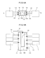
In the embodiment which is illustrated in FIGS. 2A and 2B , the radiator 11 is provided at the downstream side of the fans 5 so that it is sufficiently cooled by the cooling air CA. Usually, it is provided in the direction vertical to the direction of flow of the cooling air CA. It is arranged so that all of the cooling air CA which is supplied by the fans 5 can be supplied to it. The length of the radiator 11 is shorter than the total length of the plurality of aligned fans 5. The heat receiving members 12 are provided on the CPUs 3. The coolant piping 13 which supplies coolant to the heat receiving members 12 from the radiator 11 is provided on the main board 6 so as not to enter the second regions A2. The radiator 11 has a plurality of channels. The coolant piping 13 is connected by the manifold 16 to the plurality of channels of the radiator 11. Further, between the coolant piping 13 and the heat receiving member 12, tanks 15 which temporarily store the coolant and pumps 15 which move the coolant are provided. The configuration of the pumps 14 will be explained in detail later, but pluralities are provided at the two sides of the tanks 15. Note that, if the pumps 14 are large in capacity, the pumps 14 may also be provided at just single sides of the tanks 15.
Due to this structure, the heat receiving members 12 has the pumps 14 and the tanks 15 arranged concentrated on them in adjoining manners, so the coolant piping 13 which connects these can be shortened and space can be saved. Further, the channel resistance when the coolant flows through the inside of coolant piping 13 depends on the length of the coolant piping 13, so by making the coolant piping 13 shorter, the channel resistance of the coolant which flows through the inside of the liquid cooling system 10 can be made smaller. Further, by the amount of movement of the coolant becoming greater, heat is efficiently transferred from the heat receiving units 12 to the radiator 11, so the liquid cooling system 10 can be improved in performance.
Furthermore, the components which require strong cooling are concentrated at the first region A1 while avoiding the second regions, so the components of the liquid cooling system 10 can also be concentrated at the first region A1. As a result, the second regions A2 can be secured wide without being made narrow. On top of this, the liquid cooling system 10 does not inhibit the flow of cooling air CA to the second regions A2 and can sufficiently supply cooling air CA to the electronic components 4 which are mounted at the second regions A2. Due to these advantages, the performance of the liquid cooling system 10 is improved and it becomes possible to mount at the server a liquid cooling system 10 which cools heat generating components 3A and 3B which have 300 W or so high heat generating characteristics while not interfering with the cooling of electronic components 4 which use cooling air CA for cooling.
Here, FIG. 9 will be used to explain the features of the layout of sub boards 4A on which the electronic components 4 are mounted and the connection with the CPUs 3A and 3B. Here, the electronic components 4 are memories (DIMM). The DIMMs 4 are structured as sub boards 4A on both or one side of which a plurality of DRAM devices are mounted. Below, the electronic components 4 will also be referred to as “memories 4” or “DIMMs 4”. Pluralities of the sub boards 4A are arranged in parallel with the flow of the cooling air CA at the two sides of the CPUs 3A and 3B. For this reason, the physical wiring lengths between the DIMMs 4 and the CPUs 3A and 3B can be made the shortest.
Inside of the CPUs 3A and 3B, there are system controllers 3S and memory access controllers 3M. The memories 4 transfer data with the CPUs 3A and 3B through the memory access controllers 3M and the system controllers 3S. Data transfer between devices takes time corresponding to the length of wiring between the devices (physical distance). During that time, the data processing at the CPUs is stopped. In the present embodiment, as explained above, the physical length of wiring between the memories 4 and the CPUs 3A and 3B can be made the shortest, so the time until completion of transfer of data (memory latency) is small and the time required for data processing in the system as a whole can be shortened.
That is, in the present embodiment, the layout of the CPUs 3A and 3B and the memories 4 is given the greatest priority to in the design of the main board 6. The liquid cooling system 10 is arranged in accordance with the layout of the components which require strong cooling 3 on the main board 6. For this reason, in the present embodiment, the liquid cooling system 10 is arranged at a location offset from the center of the main board 6, while the air cooling system has a left-right asymmetric area ratio.
The channels are connected to the manifold 16. The manifold 16 has a coolant inlet part 16H and a coolant outlet part 16C. The coolant inlet part 16H is connected inside of the manifold 16 to first end parts of the four radiating channels at the left side of the manifold 16, while the coolant outlet part 16C is connected inside of the manifold 16 to first end parts of the four radiating channels at the right side of the manifold 16. The other end parts of the left side and right side radiating channels which are not connected to the coolant inlet part 16H and the coolant outlet part 16C are connected inside of the manifold 16.
The coolant (warm water) which flows to the coolant inlet part 16H from not illustrated coolant piping flows into the four radiating channels at the left side of the manifold 16, makes U-turns at the end parts, returns to the manifold 16, then flows into the four radiating channels at the right side of the manifold 16. The coolant which flows into the four radiating channels at the right side of the manifold 16 makes U-turns at the end parts to again return to the manifold 16, is discharged from the coolant outlet part 16C, and flows into not illustrated coolant piping. The coolant which flows in from the coolant inlet part 16H is warm water, but the coolant which is discharged from the coolant outlet part 16C is cooled by the radiating channels of the radiator 11, so is cold water.
The pumps 14, while not illustrated, have speed detection sensors attached to them. The operations of the pumps 14 are monitored by a control circuit (service processor) 20 to which the speed signals (pulse signals) are input. The control circuit 20 includes conversion circuits 21 which convert pulse signals to speed signals, threshold value judgment circuits 22 which compare the speeds of the pumps 14 against a threshold value, and a component judgment circuit 23 and system judgment circuit 24 which use the outputs from the threshold value judgment circuits 22 to judge if the pumps 14 are normal.
For example, when, among the six pumps 14, just one pump 14 has broken down, the speed signal from that one pump 14 is not input to the control circuit 20, but the control circuit 20 judges that with breakdown of just one pump, the cooling of the heat generating components by the liquid cooling system 10 is not hindered. Further, the component judgment circuit 23 outputs a notification of breakdown of one of the pumps 14, but the system judgment circuit 24 outputs a command for continuation of operation (OK) of the liquid cooling system so the cooling of the heat generating components by the liquid cooling system 10 is continued. By giving redundancy to control of the pumps 14 in this way, even when a pump 14 breaks down, if the cooling ability can be secured, the liquid cooling system 10 does not stop and the CPUs can continue to be cooled, so the reliability can be secured.
On the other hand, if the judgment at step 803 is that there is a pump where the speed x has not exceeded the threshold value (NO), the routine proceeds to step 804 where breakdown of that pump is notified, then the routine proceeds to step 805. At step 805, it is judged if just one pump has broken down. If just one pump has broken down (YES), as explained above, it is judged that the cooling of the heat generating components by the liquid cooling system is not hindered and the routine returns to step 802 where the speeds x of the pumps continue to be read. In this regard, when it is judged at step 805 that several pumps have broken down (NO), it is judged that the cooling of the heat generating components by the liquid cooling system is hindered and the routine proceeds to step 806 where the operation of the cooling system is stopped and this routine is ended.
The metal plate 40 has a step part 41, a CPU power source-use metal plate part 42, a CPU-use metal plate part 43, a hole 44 for avoiding interference with the mounted components, a recessed part 45, and holes 46 for insertion of the heat receiving member fastening parts 17. The CPU-use metal plate 60 has a base plate 61 and mounting holes 62 for insertion of the heat receiving member fastening parts 17. The cold plate 90 has a cold water inlet 91, coolant channel 92, CPU-use cold plate 93, U-turn channel 94, and CPU power source-use cold plate 95. The members which form the metal plate 40, CPU-use metal plate 60, and the cold plate 90 will be explained in detail later using enlarged drawings.
Here, the air barrier wall and the leakage tray which are provided at the server module of the present application will be explained. FIG. 11A is a comparative view which compares the flow of cooling air CA which flows through the inside of the server module 1 which is provided with the air cooling system and the flow of cooling air CA in the case of setting an air barrier wall 7 at the center part of the inside of the server module 1. When the server module 1 does not have the air barrier wall 7 inside it, the cooling air CA which is generated by the fans mainly flows over the main board 6 at which the low height heat generating components 3 ( CPUs 3A and 3B) are mounted since the parts where the electronic components 4 are concentrated have channel resistance.
Channel resistance is generated due to the narrow interval between components on the main board 6 due to high density mounting and the high height of the components which are mounted at such regions. That is, the electronic components 4 are DIMMs, power modules, and other components which are formed by circuits on sub boards which are mounted vertically on the main board 6, so are high in height. Therefore, the channels of the cooling air CA end up being blocked by the DIMMs, power modules, etc., so channel resistance occurs. As opposed to this, the CPUs 3A and 3B are directly mounted on the main board 6, so are lower in height compared with DIMMs, power modules, etc. DIMMs have a height from the board 6 of, for example, 33 mm. Further, the leakage tray 8 has a height from the board 6 of, for example, 26.5 mm. The lower limit value of the height of the leakage tray 8 for preventing leakage is about half of that or 13 mm, while the upper limit value of the height of the leakage tray 8 for preventing contact with the ceiling of the housing is 35 mm. If in this range of height, there will be no leakage and higher efficiency of cooling of the DIMMs and power source can be expected.
Even if the main board 6 on which low height heat generating components 3 are mounted is provided which an above-mentioned such liquid cooling system 10 as illustrated by the broken lines, the cooling air CA flows to around the liquid cooling system, so the cooling ability of the electronic components 4 by the cooling air CA falls. That is, in the region inside the broken lines, only components which require strong cooling which are covered by liquid cooling and components which require weak cooling which have a low heat generating characteristic (including no heat generation) of an extent not requiring air cooling are mounted. Despite the fact that the supply of cooling air is not required, the cooling air flows into this region. Therefore, the cooling air which is supplied to the electronic components 4 which relatively require the supply of cooling air is reduced, so the cooling performance of the electronic components 4 falls.
Therefore, to prevent the cooling air CA from flowing to around the heat generating components 3, the area around the liquid cooling system 10 which is mounted over the heat generating components 3 is covered by an air barrier wall 7. Therefore, the cooling air CA is prevented from flowing to the components which require strong cooling 3. As a result, the inflow of cooling air to the region which does not require the supply of cooling air can be prevented and all of the cooling air can be supplied to the components which require weak cooling 4 where the cooling air is required, so the cooling ability of the electronic components 4 by the cooling air CA is improved.
Furthermore, as illustrated in FIG. 11B , if forming a ceiling part 70 above the air barrier wall 7 which is provided around the heat generating components 3 and the liquid cooling system 10 which are mounted on the main board 6 and covering the heat generating components 3 and the liquid cooling system 10 as a whole by these, the cooling ability of the electronic components 4 by the cooling air CA is improved much more. Further, when providing the air barrier wall 7 around the heat generating component 3 and the liquid cooling system 10, as illustrated in FIG. 11C , if providing a curved part at the upstream side of the air barrier wall 7 or, as illustrated in FIG. 11D , if providing a tapered part at the upstream side of the air barrier wall 7, the cooling air CA more easily flows to the electronic component sides.
In this regard, in the liquid cooling system 10 which has been explained up to here, the coolant for performing the cooling is a liquid (for example, water), so there is a possibility of coolant leaking from the coolant piping 13 or connecting parts of the coolant piping 13 and the heat receiving members 12, pumps 14, or tanks 15. Further, if coolant leaks from the liquid cooling system 10, the leaked coolant is liable to overflow on to the main board 6 whereby the electronic components 4 are liable to be flooded and the circuits to short. Therefore, it is considered to place a leakage tray which prevents leakage of leaked coolant to other locations below the heat receiving members, pumps 14, and tanks 15 of the liquid cooling system 10.
The leakage tray 8 is provided with a base plate 80, CPU contact- use holes 8A and 8B, power circuit contact-use holes 8HA and 8HB, and the air barrier wall 7 which sticks out from the periphery of the base plate 80. The CPU contact- use holes 8A and 8B are holes for insertion of the CPUs 3A and 3B on the main board 6, while the power circuit contact-use holes 8HA and 8HB are holes for insertion of CPU- use power circuits 30A and 30B. Further, the base plate 80 between the CPU contact- use holes 8A and 8B is provided with a sleeve 8S. The sleeve 8S will be explained later.
The air barrier wall 7 is formed by extending and bending upward the outer edge part of the base plate 80 of the leakage tray 8. This is because the outer edge part of the base plate 80 of the leakage tray 8 requires a bent part for keeping leakage from the liquid cooling system 10 inside the leakage tray 8, so this bent part is extended upward to increase the wall height and serve also as an air barrier wall 7. If attaching the leakage tray 8 on the main board 6 and attaching the liquid cooling system 10 over that, as illustrated in FIG. 13A , the air barrier wall 7 sticks out around the pumps 14 and the tanks 15 and therefore the cooling air no longer enters the region where the pumps 14 and the tanks 15 are provided.
On the other hand, FIG. 14A is a partial cross-sectional view of the liquid cooling system 10 which is illustrated in FIG. 13A in the direction along the flow of the cooling air. FIG. 14A illustrates only the part of the CPU 3A. The cross-section of the CPU 3B side is omitted. From this figure as well, it will be understood that the heat receiving member fastening parts 17 are screwed by the male screws 19 with the fastening plate 18 at the rear side of the main board 6 and that the springs 17B bias the metal plate 40 from the head 17H side to the main board 6 side.
Here, the engaged state of the metal plate 40, CPU-use metal plate 60, and the cold plate 90 which are illustrated in FIG. 10 and the main board 6 and leakage tray 8 which are illustrated in FIG. 12 will be explained using FIG. 14A . The main board 6 mounts as the CPU-use power circuit 30A a first component 30A1 and a second component 30A2 and a CPU 3A. In the state of the main board 6 having the leakage tray 8 attached, the CPU-use power circuit 30A enters the power contact-use hole 8HA of the leakage tray 8, while the CPU 3A enters the CPU contact-use hole 8A of the leakage tray 8. At the surface of the base 80 of the leakage tray 8 on the main board 6 side, the CPU contact- use holes 8A and 8B may be surrounded by packing. The packing is adhered around the CPUs 3A and 3B whereby the water-stemming effect is enhanced.
The cold plate 90 which is illustrated in FIG. 10 includes the CPU-use cold plate 93 and the CPU power source-use cold plate 95. The CPU-use cold plate 93 has two channels. The end of one channel is connected to the cold water inlet 91, while the other end is connected to the U-turn channel 94. The other channel has one end connected to the U-turn channel 94, while has the other end connected to the coolant channel 92. The coolant channel 92 is divided inside it into two channels. The coolant channel 92 with the cold water inlet 91 and the coolant channel 92 through which coolant which has passed the U-turn channel 94 returns are not communicated. Therefore, the entire amount of the coolant which has passed through the U-turn channel 94 and returned to the coolant channel 92 flows into the CPU power source-use cold plate 95 and flows into the warm water pipe 13H of the coolant piping 13. The flow of the coolant is illustrated by the arrow marks in FIG. 10 .
If the liquid cooling system 10 is attached over the leakage tray 8, the CPU-use cold plate 93 of the cold plate 90 which forms the heat receiving member 12 is positioned right above the CPU 3A, while the CPU power source-use cold plate 95 is positioned right above the CPU-use power circuit 30A. At this time, the CPU 3A is laid over the CPU-use cold plate 93 through a heat conducting sheet 31, but the first component 30A1 of the CPU-use power circuit 30A is low in height, so is not laid over the CPU power source-use cold plate 95. Therefore, the first component 30A1 of the CPU-use power circuit 30A has provided on it a metal rod 32 for contact with the CPU power source-use cold plate 95 through the heat conducting sheet 31.
The CPU metal plate 60 is provided with mounting holes 62 at the four corners of the base plate 61. The heat receiving member fastening parts 17 which are inserted through the mounting holes 62 are used to lay the base plate 61 over the CPU-use cold plate 93.
The metal plate 40 is provided with a CPU-use metal plate part 43. This CPU-use metal plate part 43 is provided with holes 46 which overlap the mounting holes 62 which are formed at the four corners of the base plate 61. One end part of the metal plate 40 has a step part 41. This step part 41 is provided with springiness. Further, the CPU power source-use metal plate part 42 which follows the step part 41 is much lower than the CPU-use metal plate part 43 and is formed to approach the main board 6 at the time of mounting. In the state where the metal plate 40 is attached by the heat receiving member fastening parts 17, the CPU-use metal plate part 43 is laid over the base plate 61 of the CPU metal plate 60 and the CPU power source-use metal plate part 42 is laid over the CPU power source-use cold plate 95. Further, in the state where the CPU-use metal plate part 43 of the metal plate 40 is laid over the base plate 61 of the CPU metal plate 60, the height of the bottom surface of the CPU power source-use metal plate part 42 from the main board 6 is lower than the height of the top surface of the CPU power source-use cold plate 95 from the main board 6. For this reason, in the state where the metal plate 40 is attached by the heat receiving member fastening parts 17 and the CPU power source-use metal plate part 42 is laid over the CPU power source-use cold plate 95, the springiness of the step part 41 causes the CPU power source-use cold plate 95 to be biased by the CPU power source-use metal plate part 42.
Due to the above such configuration, the heat which is generated by the CPUs 3A and 3B and components in the CPU-use power source component 30A which are arranged in the first region A1 of the main board 6 is absorbed by the CPU-use cold plate 93 and the CPU power source-use cold plate 95.
Note that, if making the bottom plate of the leakage tray 8 for preventing leakage from the liquid cooling system 10, as illustrated in FIG. 14B and FIG. 14C , a double layer structure, it becomes harder for the coolant which has leaked from the liquid cooling system 10 to escape. FIG. 14B illustrates an embodiment wherein a drain 83 is provided at a double layer bottom 84. FIG. 14C illustrates the configuration of an embodiment which is provided with two slanted bottom plates 85, 86. Further, it is possible to not make the leakage tray 8 a double layer bottom but, as in another embodiment which is illustrated in FIG. 14D , insert a water absorbing sheet 87 at the bottom plate of the leakage tray 8 so as to make it difficult for the coolant which has leaked from the liquid cooling system 10 to escape.
Like in the second embodiment of the server module 1, when the server module 1 is provided with the XB unit 71, at the inside of the XB unit 71, as illustrated in FIG. 17 , there is an XB chip 73 which generates a large amount of heat at the time of operation. Further, this XB chip 73 is a weak cooling component which requires cooling by cooling air. For this reason, in the second embodiment of the server module 1, the first region A1 and the two second regions A2 are shifted to one side with respect to the housing of the server module 1. Cooling air CA is sent through the part opened by the shift to the XB unit 71.
In this case, the bottom surface of the main board 6 of the second system unit U2 has a connector 70 which is illustrated in FIG. 19 attached to it. The connector 70 is for connecting a circuit at the second system unit U2 to the circuit at the first system unit U1 when the second system unit U2 is attached laid over the top side of first system unit U2. If the first system unit U1 and the second system unit U2 are electrically connected through the connector 70, the CPUs 3A, 3B which are at one main board 6 can use the data of the DIMMs 4 at the other main board 6.
The position of the connector 70 which is provided at the bottom surface of the second system unit U2 is the same as the position of the sleeve 8S at the leakage tray 9 which is attached to the main board 6 of the first system unit U1. In this case, the main board 6 of the first system unit U1 mounts a connector (pair connector) which mates with the connector 70 which is provided at the bottom surface of the main board 6 of the second system unit U2 inside the sleeve 8S of the leakage tray 8. Therefore, if the second system unit U2 is attached laid over the top side of the first system unit U1, the connector 70 which is at the second system unit U2 is inserted into the sleeve 8S at the first system unit U1 and connected to the pair connector.
In this way, according to the present application, it is possible to provide a liquid cooling system which has the ability to radiate off a high amount of generated heat, which can be mounted at a high density at a predetermined device while saving space, and, furthermore, which enables a mountable area of components other than those for cooling to be broadly secured. Further, it is possible to provide a liquid cooling system which has pumps for transport of coolant redundantly configured and redundantly controlled and thereby secures a high reliability and does not obstruct cooling of other components besides the ones being cooled and to provide an electronic apparatus which mounts the same.
The liquid cooling system of the present application enables cooling of two 300 W CPUs by a pump flow rate of 0.9 liter/min in the case of a radiator of a size of a height of 36 mm, a depth of 59 mm, and a width of 350 mm. Further, the path of the cooling air which cools the DIMMs only has a radiator in it, so the cooling air efficiently hits the DIMMs and therefore 256 W of DIMMs (32 8 W DIMMs) becomes possible. Further, if assuming notification of abnormalities in the pumps and replacements being installed in a short time from the occurrence of the abnormalities, the possibility of two pumps simultaneously breaking down is eliminated and the possibility of system trouble occurring in the liquid cooling system can be eliminated.
Although only some exemplary embodiments of this invention have been described in detail above, those skilled in the art will readily appreciated that many modifications are possible in the exemplary embodiments without materially departing from the novel teachings and advantages of this invention. Accordingly, all such modifications are intended to be included within the scope of this invention.
Claims (22)
1. An electronic module comprising:
at least one fan;
at least one main board positioned downstream in an airflow which the fan generates;
at least one processer on the main board;
at least one memory board on the main board; and
a liquid cooling unit on the main board, the liquid cooing unit including a heat receiving member in which a liquid coolant flows and a coolant piping, the heat receiving member mounted on the processer, the coolant piping circulating the liquid coolant between a radiator and the heat receiving member, the radiator positioned downstream in the airflow which the fan generates, the radiator be cooling the liquid coolant,
wherein the memory board and the liquid cooling unit are parallel to a direction in which the fan blows the airflow.
2. The electronic module according to claim 1 ,
wherein the coolant piping is connected by a manifold to the radiator, and
wherein the radiator comprises at least one radiating channel at a left side of the manifold and at least one radiating channel at a right side of the manifold.
3. The electronic module according to claim 1 , further comprising,
at least one pump letting the liquid coolant move in the liquid cooling unit; and
at least one tank temporarily stores the liquid coolant,
wherein the pump slants.
4. The electronic module according to claim 3 ,
wherein the pump and the tank mount on the heat receiving member,
wherein the pump slants to the heat receiving member.
5. The electronic module according to claim 3 ,
wherein the coolant piping connects the tank, the tank connects at least one pump, the pump sucks the liquid coolant from the tank by a suction pipe and returns the liquid coolant to the tank by a discharge pipe, the returned liquid coolant is merged and passes through the coolant piping.
6. The electronic module according to claim 5 ,
wherein the pump and the tank mount on the heat receiving member,
wherein a pair of the suction pipe and the discharge pipe connects to the tank at a slant to the heat receiving member.
7. The electronic module according to claim 1 ,
wherein the heat receiving member comprising,
a first plate positioned above the processor; and
a second plate positioned above a peripheral,
wherein the liquid coolant flows in the first plate and in the second plate.
8. The electronic module according to claim 7 ,
wherein the peripheral includes at least a CPU power circuit.
9. The electronic module according to claim 1 , further comprising,
a control circuit controlling the liquid cooling unit,
wherein if a revolution speed of the pump does not exceed a threshold value, the control circuit judges that the pump breaks down, if a plurality of the pump breaks down, the control circuit configures to stop the liquid cooling unit.
10. The electronic module according to claim 1 , wherein the pump places on a pump placer with V-groove.
11. The electronic module according to claim 1 , wherein the pump is attached with a buffer plate between the pump and a pump mounting fitting.
12. The electronic module according to claim 1 ,
wherein a plurality of the main board are stacked vertically, the plurality of the main board are connected with at least one connection unit including at least one chip, the airflow sent to the connection unit is sent through a third area, the third area is not a first area of the processer and a second area of the memory board.
13. The electronic module according to claim 12 ,
wherein the plurality of the main board connect with a connector.
14. The electronic module according to claim 13 ,
wherein a memory on one main board connects a memory on another main board electrically with the connector.
15. The electronic module according to claim 1 , wherein the processer is surrounded by an air barrier wall.
16. The electronic module according to claim 15 , wherein a ceiling is formed above the air barrier wall.
17. The electronic module according to claim 15 , wherein the air barrier wall is curved or tapered.
18. An cooling method for an electronic module, the cooling method comprising:
generating an airflow by a fan on the electronic module;
cooling a memory board by the airflow;
circulating a liquid coolant in a coolant piping, the liquid coolant being between a radiator and a heat receiving member; and
cooling the liquid coolant by the radiator;
wherein the electronic module comprising;
a main board positioned downstream in the airflow which the fan generates;
a processer on the main board;
the memory board on the main board;
a liquid cooling unit on the main board,
the liquid cooing unit including a heat receiving member in which the liquid coolant flows and the coolant piping, the heat receiving member mounted on the processer;
the radiator positioned downstream in the airflow which the fan generates; and
the memory board and the liquid cooling unit being parallel to a direction in which the fan blows the airflow.
19. The cooling method according to claim 18 , further comprising,
moving the liquid coolant in the liquid cooling unit by a pump; and
storing temporarily the liquid coolant in a tank,
wherein the pump slants.
20. The cooling method according to claim 18 , further comprising,
sucking the liquid coolant from a tank through a suction pipe;
returning the liquid coolant to the tank through a discharge pipe;
merging the returned liquid coolant; and
passing the merged liquid coolant through the coolant piping,
wherein the coolant piping connects the tank, the tank connects a pump.
21. The cooling method according to claim 18 , further comprising,
controlling the liquid cooling unit by a control circuit,
wherein if a revolution speed of the pump does not exceed a threshold value, the control circuit judges that the pump breaks down, if a plurality of the pump breaks down, the control circuit configures to stop the liquid cooling unit.
22. An cooling method for an electronic module, the cooling method comprising:
generating an airflow by a fan on the electronic module;
cooling a processer by circulating a liquid coolant in a coolant piping being between a radiator and a heat receiving member;
cooling a memory board by the airflow over the radiator;
cooling a connection unit by the airflow over the radiator and a third area, the third area not being a first area of the processer and a second area of the memory board, a plurality of the main board stacked vertically being connected with the connection unit, the airflow sent to the connection unit being sent through the third area; and
cooling the liquid coolant by the radiator;
wherein the electronic module comprising;
the main board positioned downstream in the airflow;
the processer on the main board;
the memory board on the main board;
the liquid cooling unit on the main board,
the liquid cooing unit including the heat receiving member in which the liquid coolant flows and the coolant piping, the heat receiving member mounted on the processer; and
the radiator positioned downstream in the airflow,
wherein the memory board and the liquid cooling unit being parallel to a direction in which the fan blows the airflow,
wherein the plurality of main board connect with a connector, the connector is positioned between a plurality of processor, a memory on one main board connects a memory on another main board electrically with the connector.
Priority Applications (1)
| Application Number | Priority Date | Filing Date | Title |
|---|---|---|---|
| US14/028,963 US9223362B2 (en) | 2012-09-07 | 2013-09-17 | Electronic apparatus and cooling module mounted in that electronic apparatus |
Applications Claiming Priority (4)
| Application Number | Priority Date | Filing Date | Title |
|---|---|---|---|
| JP2012-197918 | 2012-09-07 | ||
| JP2012197918A JP6127416B2 (en) | 2012-09-07 | 2012-09-07 | Electronics |
| US13/673,282 US8564951B1 (en) | 2012-09-07 | 2012-11-09 | Electronic apparatus and cooling module mounted in that electronic apparatus |
| US14/028,963 US9223362B2 (en) | 2012-09-07 | 2013-09-17 | Electronic apparatus and cooling module mounted in that electronic apparatus |
Related Parent Applications (1)
| Application Number | Title | Priority Date | Filing Date |
|---|---|---|---|
| US13/673,282 Continuation US8564951B1 (en) | 2012-09-07 | 2012-11-09 | Electronic apparatus and cooling module mounted in that electronic apparatus |
Publications (2)
| Publication Number | Publication Date |
|---|---|
| US20140071616A1 US20140071616A1 (en) | 2014-03-13 |
| US9223362B2 true US9223362B2 (en) | 2015-12-29 |
Family
ID=49080766
Family Applications (2)
| Application Number | Title | Priority Date | Filing Date |
|---|---|---|---|
| US13/673,282 Active US8564951B1 (en) | 2012-09-07 | 2012-11-09 | Electronic apparatus and cooling module mounted in that electronic apparatus |
| US14/028,963 Active 2033-09-30 US9223362B2 (en) | 2012-09-07 | 2013-09-17 | Electronic apparatus and cooling module mounted in that electronic apparatus |
Family Applications Before (1)
| Application Number | Title | Priority Date | Filing Date |
|---|---|---|---|
| US13/673,282 Active US8564951B1 (en) | 2012-09-07 | 2012-11-09 | Electronic apparatus and cooling module mounted in that electronic apparatus |
Country Status (6)
| Country | Link |
|---|---|
| US (2) | US8564951B1 (en) |
| EP (1) | EP2706833B1 (en) |
| JP (1) | JP6127416B2 (en) |
| KR (1) | KR20140032894A (en) |
| CN (1) | CN103677180A (en) |
| TW (1) | TW201419994A (en) |
Cited By (4)
| Publication number | Priority date | Publication date | Assignee | Title |
|---|---|---|---|---|
| US9363927B2 (en) * | 2014-09-12 | 2016-06-07 | Lanner Electronic Inc. | Electrical signal computing module capable of accommodating printed circuit board |
| US20170181317A1 (en) * | 2015-12-21 | 2017-06-22 | Man Zai Industrial Co., Ltd. | Liquid-cooling heat sink |
| US11015608B2 (en) | 2018-12-10 | 2021-05-25 | Hewlett Packard Enterprise Development Lp | Axial flow pump with reduced height dimension |
| US11152283B2 (en) | 2018-11-15 | 2021-10-19 | Hewlett Packard Enterprise Development Lp | Rack and row-scale cooling |
Families Citing this family (54)
| Publication number | Priority date | Publication date | Assignee | Title |
|---|---|---|---|---|
| CN102789290A (en) * | 2011-05-20 | 2012-11-21 | 鸿富锦精密工业(深圳)有限公司 | Server and mainboard thereof |
| TWD164333S (en) * | 2013-08-06 | 2014-11-21 | 富士通股份有限公司 | Radiator for electronic device |
| CN104378949B (en) * | 2013-08-12 | 2017-04-26 | 英业达科技有限公司 | Server and heat dissipation assembly thereof |
| CN107211560A (en) * | 2015-02-17 | 2017-09-26 | 慧与发展有限责任合伙企业 | Fluid manifold |
| JP6497113B2 (en) * | 2015-02-19 | 2019-04-10 | 富士通株式会社 | Electronic device and mounting method of mounting unit |
| JP6447267B2 (en) * | 2015-03-11 | 2019-01-09 | 富士通株式会社 | Unit device |
| US10582626B2 (en) * | 2015-04-29 | 2020-03-03 | Hewlett Packard Enterprise Development Lp | Converged infrastructure manager |
| KR102403512B1 (en) | 2015-04-30 | 2022-05-31 | 삼성전자주식회사 | Outdoor unit of air conditioner, control device applying the same |
| WO2016191374A1 (en) * | 2015-05-22 | 2016-12-01 | Teza Technologies LLC | Fluid cooled server and radiator |
| US9655281B2 (en) | 2015-06-26 | 2017-05-16 | Seagate Technology Llc | Modular cooling system |
| US10386896B2 (en) * | 2015-10-29 | 2019-08-20 | Beijing Deepcool Industries Co., Ltd. | Water cooling system for a computer and water cooling case having the same |
| JP6127218B1 (en) * | 2015-11-11 | 2017-05-10 | 株式会社ExaScaler | Electronic equipment cooling system |
| CN108369442A (en) * | 2015-11-11 | 2018-08-03 | 株式会社ExaScaler | The cooling system of electronic equipment |
| TWI554871B (en) * | 2015-12-15 | 2016-10-21 | 技嘉科技股份有限公司 | Hear dissipating module |
| US10146231B2 (en) | 2015-12-21 | 2018-12-04 | Dell Products, L.P. | Liquid flow control based upon energy balance and fan speed for controlling exhaust air temperature |
| US10206312B2 (en) * | 2015-12-21 | 2019-02-12 | Dell Products, L.P. | Liquid cooled rack information handling system having storage drive carrier for leak containment and vibration mitigation |
| US10010013B2 (en) | 2015-12-21 | 2018-06-26 | Dell Products, L.P. | Scalable rack-mount air-to-liquid heat exchanger |
| US9839164B2 (en) | 2015-12-21 | 2017-12-05 | Dell Products, L.P. | Rack information handling system having modular liquid distribution (MLD) conduits |
| US9795065B2 (en) | 2015-12-21 | 2017-10-17 | Dell Products, L.P. | Integrated air-spring for hydraulic force damping of a rigid liquid cooling subsystem |
| US10064314B2 (en) | 2015-12-21 | 2018-08-28 | Dell Products, L.P. | Runtime service of liquid cooled servers operating under positive hydraulic pressure without impacting component performance |
| US10156873B2 (en) | 2015-12-21 | 2018-12-18 | Dell Products, L.P. | Information handling system having fluid manifold with embedded heat exchanger system |
| CN105431020B (en) * | 2015-12-29 | 2018-10-30 | 曙光信息产业(北京)有限公司 | Liquid cooling system for server |
| US10080067B2 (en) * | 2015-12-31 | 2018-09-18 | Infinera Corporation | Heat relay network system for telecommunication equipment |
| CN107637188A (en) * | 2016-02-16 | 2018-01-26 | 慧与发展有限责任合伙企业 | The air and liquid cooling of electronic equipment |
| CN105739564B (en) * | 2016-02-21 | 2017-10-13 | 洛阳理工学院 | A kind of system for controlling case temperature |
| US10349557B2 (en) | 2016-02-24 | 2019-07-09 | Thermal Corp. | Electronics rack with compliant heat pipe |
| US10136556B2 (en) | 2016-02-24 | 2018-11-20 | Thermal Corp. | Electronics rack with selective engagement of heat sink |
| JP7063448B2 (en) * | 2017-09-07 | 2022-05-09 | Necプラットフォームズ株式会社 | Electronics |
| US11263508B2 (en) * | 2017-09-22 | 2022-03-01 | Samsung Electronics Co., Ltd. | Modular NGSFF module to meet different density and length requirements |
| TWI685182B (en) * | 2017-09-29 | 2020-02-11 | 雙鴻科技股份有限公司 | Electronic device with liquid cooling function and liquid cooling module and radiator thereof |
| CN107885295A (en) * | 2017-11-08 | 2018-04-06 | 北京图森未来科技有限公司 | A kind of cooling system |
| CN107765795A (en) | 2017-11-08 | 2018-03-06 | 北京图森未来科技有限公司 | A kind of computer server |
| US10834853B2 (en) * | 2018-03-02 | 2020-11-10 | Micron Technology, Inc. | Electronic device with a card-level thermal regulator mechanism and associated systems, devices, and methods |
| AT521021B1 (en) * | 2018-05-25 | 2019-10-15 | Miba Energy Holding Gmbh | Power module with fluid protection |
| US11467637B2 (en) | 2018-07-31 | 2022-10-11 | Wuxi Kalannipu Thermal Management Technology Co., Ltd. | Modular computer cooling system |
| DE102018119201B3 (en) * | 2018-08-07 | 2019-09-26 | Fujitsu Limited | computer arrangement |
| CN109062375A (en) * | 2018-08-21 | 2018-12-21 | 河南省云乐科技有限公司 | A kind of novel computer server radiating case |
| US10582639B1 (en) * | 2018-09-14 | 2020-03-03 | Cisco Technology, Inc. | Liquid cooling distribution in a modular electronic system |
| CN108958416A (en) * | 2018-09-17 | 2018-12-07 | 李汝和 | A kind of heat radiating type computer based on block chain technology |
| US10667423B2 (en) * | 2018-10-26 | 2020-05-26 | Dell Products L.P. | Connector cooling and status indicator system |
| JP7131312B2 (en) * | 2018-11-07 | 2022-09-06 | 日本電産株式会社 | Cooling system |
| US10849223B2 (en) * | 2019-03-06 | 2020-11-24 | Cisco Technology, Inc. | Multi-socket server assembly |
| CN111240445A (en) * | 2020-01-03 | 2020-06-05 | 英业达科技有限公司 | Server heat radiation structure |
| CN113093872B (en) * | 2020-01-08 | 2022-09-02 | 富联精密电子(天津)有限公司 | Server |
| US11044834B1 (en) * | 2020-02-21 | 2021-06-22 | Google Llc | Inverted liquid cooling system |
| CN110989811B (en) * | 2020-03-03 | 2020-06-02 | 北京中航科电测控技术股份有限公司 | Rapid heat dissipation computer motherboard based on godson 3A3000 treater |
| US11157050B1 (en) * | 2020-04-28 | 2021-10-26 | Hewlett Packard Enterprise Development Lp | Compute node tray cooling |
| CN111465285B (en) * | 2020-04-30 | 2022-06-21 | 湖北三江航天万峰科技发展有限公司 | Heat radiation structure and power supply module of high density digital power supply |
| CN111538387B (en) * | 2020-05-14 | 2023-04-07 | 广东理工学院 | Computer with heat dissipation auxiliary constant temperature circuit |
| CN113199936B (en) * | 2021-06-18 | 2023-03-17 | 一汽解放汽车有限公司 | Pipeline distribution design method for vehicle cooling system and vehicle cooling system |
| US11910563B2 (en) * | 2021-06-21 | 2024-02-20 | Quanta Computer Inc. | Liquid cooling module with movable radiators |
| CN114756100B (en) * | 2022-04-26 | 2023-08-15 | 铵泰克(北京)科技有限公司 | High-integration industrial personal computer |
| TWI805363B (en) * | 2022-05-11 | 2023-06-11 | 英業達股份有限公司 | Liquid cooling plate for cpu |
| CN116027869B (en) * | 2023-02-15 | 2023-07-25 | 兰洋(宁波)科技有限公司 | Temperature control system and control method for server |
Citations (19)
| Publication number | Priority date | Publication date | Assignee | Title |
|---|---|---|---|---|
| US6587343B2 (en) | 2001-08-29 | 2003-07-01 | Sun Microsystems, Inc. | Water-cooled system and method for cooling electronic components |
| JP2005038112A (en) | 2003-07-18 | 2005-02-10 | Hitachi Ltd | Liquid cooling system and radiator |
| US6862185B2 (en) | 2003-01-15 | 2005-03-01 | Hewlett-Packard Development Company, L.P. | Systems and methods that use at least one component to remove the heat generated by at least one other component |
| US6997247B2 (en) * | 2004-04-29 | 2006-02-14 | Hewlett-Packard Development Company, L.P. | Multiple-pass heat exchanger with gaps between fins of adjacent tube segments |
| US7002799B2 (en) * | 2004-04-19 | 2006-02-21 | Hewlett-Packard Development Company, L.P. | External liquid loop heat exchanger for an electronic system |
| US7068509B2 (en) | 2004-02-03 | 2006-06-27 | Hewlett-Packard Development Company, L.P. | Small form factor cooling system |
| US7203063B2 (en) * | 2004-05-21 | 2007-04-10 | Hewlett-Packard Development Company, L.P. | Small form factor liquid loop cooling system |
| US20070125523A1 (en) | 2005-12-01 | 2007-06-07 | Bhatti Mohinder S | Low profile liquid cooled server heat sink |
| US7252139B2 (en) | 2001-08-29 | 2007-08-07 | Sun Microsystems, Inc. | Method and system for cooling electronic components |
| US7280358B2 (en) * | 2004-04-19 | 2007-10-09 | Hewlett-Packard Development Company, L.P. | Liquid loop with multiple heat exchangers for efficient space utilization |
| US20080259566A1 (en) | 2007-04-16 | 2008-10-23 | Stephen Samuel Fried | Efficiently cool data centers and electronic enclosures using loop heat pipes |
| US7457116B2 (en) * | 2006-12-27 | 2008-11-25 | Intel Corporation | Method and system to cool memory |
| US7477516B2 (en) | 2006-08-17 | 2009-01-13 | Delphi Technologies, Inc. | Air cooled computer chip |
| US7551440B2 (en) * | 2007-01-24 | 2009-06-23 | Hewlett-Packard Development Company, L.P. | System and method for cooling an electronic component |
| US7667967B1 (en) | 2008-08-06 | 2010-02-23 | Sun Microsystems, Inc. | Liquid-cooled rack with optimized rack heat exchanger design for non-uniform power dissipation |
| US20100300652A1 (en) | 2009-05-27 | 2010-12-02 | Hon Hai Precision Industry Co., Ltd | Heat Dissipating System |
| US8051897B2 (en) * | 2005-11-30 | 2011-11-08 | International Business Machines Corporation | Redundant assembly for a liquid and air cooled module |
| US20110272128A1 (en) | 2010-05-10 | 2011-11-10 | Fujitsu Limited | Radiator and electronic device having the same |
| US8385069B2 (en) | 2010-05-24 | 2013-02-26 | International Business Machines Corporation | Liquid coolant conduit secured in an unused socket for memory module cooling |
Family Cites Families (14)
| Publication number | Priority date | Publication date | Assignee | Title |
|---|---|---|---|---|
| JPH02144997A (en) * | 1988-11-28 | 1990-06-04 | Hitachi Ltd | Electric circuit device |
| JPH0426597U (en) * | 1990-06-27 | 1992-03-03 | ||
| JPH05109798A (en) | 1991-10-15 | 1993-04-30 | Rohm Co Ltd | Forming method of mold part in electronic components |
| JP4512296B2 (en) * | 2001-08-22 | 2010-07-28 | 株式会社日立製作所 | Liquid cooling system for portable information processing equipment |
| CN100418037C (en) * | 2003-06-27 | 2008-09-10 | 日本电气株式会社 | Cooler for electronic equipment |
| JP2005122503A (en) * | 2003-10-17 | 2005-05-12 | Hitachi Ltd | Cooling apparatus and electronic equipment incorporating the same |
| US7325588B2 (en) * | 2004-04-29 | 2008-02-05 | Hewlett-Packard Development Company, L.P. | High serviceability liquid cooling loop using flexible bellows |
| JP2006135202A (en) * | 2004-11-09 | 2006-05-25 | Yaskawa Electric Corp | Heat radiating structure for electronic appliance |
| US7641101B2 (en) * | 2006-10-10 | 2010-01-05 | International Business Machines Corporation | Method of assembling a cooling system for a multi-component electronics system |
| JP2008211001A (en) * | 2007-02-27 | 2008-09-11 | Matsushita Electric Ind Co Ltd | Electronic device cooling apparatus |
| JP2008287733A (en) * | 2008-06-19 | 2008-11-27 | Hitachi Ltd | Liquid cooling system |
| US8014150B2 (en) * | 2009-06-25 | 2011-09-06 | International Business Machines Corporation | Cooled electronic module with pump-enhanced, dielectric fluid immersion-cooling |
| JP2011187762A (en) * | 2010-03-10 | 2011-09-22 | Fujitsu Ltd | Cooling device and electronic device |
| TW201144994A (en) * | 2010-06-15 | 2011-12-16 | Hon Hai Prec Ind Co Ltd | Server and server system |
-
2012
- 2012-09-07 JP JP2012197918A patent/JP6127416B2/en active Active
- 2012-11-09 US US13/673,282 patent/US8564951B1/en active Active
-
2013
- 2013-08-26 TW TW102130439A patent/TW201419994A/en unknown
- 2013-08-30 EP EP13182504.4A patent/EP2706833B1/en active Active
- 2013-08-30 KR KR1020130103717A patent/KR20140032894A/en not_active Application Discontinuation
- 2013-09-05 CN CN201310399769.0A patent/CN103677180A/en active Pending
- 2013-09-17 US US14/028,963 patent/US9223362B2/en active Active
Patent Citations (21)
| Publication number | Priority date | Publication date | Assignee | Title |
|---|---|---|---|---|
| US7252139B2 (en) | 2001-08-29 | 2007-08-07 | Sun Microsystems, Inc. | Method and system for cooling electronic components |
| US6587343B2 (en) | 2001-08-29 | 2003-07-01 | Sun Microsystems, Inc. | Water-cooled system and method for cooling electronic components |
| US6862185B2 (en) | 2003-01-15 | 2005-03-01 | Hewlett-Packard Development Company, L.P. | Systems and methods that use at least one component to remove the heat generated by at least one other component |
| JP2005038112A (en) | 2003-07-18 | 2005-02-10 | Hitachi Ltd | Liquid cooling system and radiator |
| US7068509B2 (en) | 2004-02-03 | 2006-06-27 | Hewlett-Packard Development Company, L.P. | Small form factor cooling system |
| US7002799B2 (en) * | 2004-04-19 | 2006-02-21 | Hewlett-Packard Development Company, L.P. | External liquid loop heat exchanger for an electronic system |
| US7280358B2 (en) * | 2004-04-19 | 2007-10-09 | Hewlett-Packard Development Company, L.P. | Liquid loop with multiple heat exchangers for efficient space utilization |
| US6997247B2 (en) * | 2004-04-29 | 2006-02-14 | Hewlett-Packard Development Company, L.P. | Multiple-pass heat exchanger with gaps between fins of adjacent tube segments |
| US7203063B2 (en) * | 2004-05-21 | 2007-04-10 | Hewlett-Packard Development Company, L.P. | Small form factor liquid loop cooling system |
| US8051897B2 (en) * | 2005-11-30 | 2011-11-08 | International Business Machines Corporation | Redundant assembly for a liquid and air cooled module |
| US20070125523A1 (en) | 2005-12-01 | 2007-06-07 | Bhatti Mohinder S | Low profile liquid cooled server heat sink |
| US7477516B2 (en) | 2006-08-17 | 2009-01-13 | Delphi Technologies, Inc. | Air cooled computer chip |
| US7457116B2 (en) * | 2006-12-27 | 2008-11-25 | Intel Corporation | Method and system to cool memory |
| US7551440B2 (en) * | 2007-01-24 | 2009-06-23 | Hewlett-Packard Development Company, L.P. | System and method for cooling an electronic component |
| US20080259566A1 (en) | 2007-04-16 | 2008-10-23 | Stephen Samuel Fried | Efficiently cool data centers and electronic enclosures using loop heat pipes |
| US7957132B2 (en) | 2007-04-16 | 2011-06-07 | Fried Stephen S | Efficiently cool data centers and electronic enclosures using loop heat pipes |
| US7667967B1 (en) | 2008-08-06 | 2010-02-23 | Sun Microsystems, Inc. | Liquid-cooled rack with optimized rack heat exchanger design for non-uniform power dissipation |
| US20100300652A1 (en) | 2009-05-27 | 2010-12-02 | Hon Hai Precision Industry Co., Ltd | Heat Dissipating System |
| US8077463B2 (en) * | 2009-05-27 | 2011-12-13 | Hon Hai Precision Industry Co., Ltd. | Heat dissipating system |
| US20110272128A1 (en) | 2010-05-10 | 2011-11-10 | Fujitsu Limited | Radiator and electronic device having the same |
| US8385069B2 (en) | 2010-05-24 | 2013-02-26 | International Business Machines Corporation | Liquid coolant conduit secured in an unused socket for memory module cooling |
Non-Patent Citations (1)
| Title |
|---|
| Korean Office Action Notice of Preliminary Rejection Korean patent application No. 10-2013-103717 Mailed Jul. 30, 2014. |
Cited By (4)
| Publication number | Priority date | Publication date | Assignee | Title |
|---|---|---|---|---|
| US9363927B2 (en) * | 2014-09-12 | 2016-06-07 | Lanner Electronic Inc. | Electrical signal computing module capable of accommodating printed circuit board |
| US20170181317A1 (en) * | 2015-12-21 | 2017-06-22 | Man Zai Industrial Co., Ltd. | Liquid-cooling heat sink |
| US11152283B2 (en) | 2018-11-15 | 2021-10-19 | Hewlett Packard Enterprise Development Lp | Rack and row-scale cooling |
| US11015608B2 (en) | 2018-12-10 | 2021-05-25 | Hewlett Packard Enterprise Development Lp | Axial flow pump with reduced height dimension |
Also Published As
| Publication number | Publication date |
|---|---|
| JP2014053504A (en) | 2014-03-20 |
| KR20140032894A (en) | 2014-03-17 |
| TW201419994A (en) | 2014-05-16 |
| US8564951B1 (en) | 2013-10-22 |
| JP6127416B2 (en) | 2017-05-17 |
| CN103677180A (en) | 2014-03-26 |
| EP2706833A2 (en) | 2014-03-12 |
| EP2706833A3 (en) | 2017-11-15 |
| US20140071616A1 (en) | 2014-03-13 |
| EP2706833B1 (en) | 2020-07-15 |
Similar Documents
| Publication | Publication Date | Title |
|---|---|---|
| US9223362B2 (en) | Electronic apparatus and cooling module mounted in that electronic apparatus | |
| US20040008483A1 (en) | Water cooling type cooling system for electronic device | |
| US20040008490A1 (en) | Water cooling type soft cooling jacket for electronic device and buffer jacket using the same | |
| US9743562B2 (en) | Liquid-cooled heat sink configured to facilitate drainage | |
| EP2706568B1 (en) | Cooling unit and electronic equipment | |
| US8587943B2 (en) | Liquid-cooling memory modules with liquid flow pipes between memory module sockets | |
| US7743820B2 (en) | Liquid cooling unit with auxillary heat exchanger and auxillary pump | |
| US6778394B2 (en) | Electronic device having a heat dissipation member | |
| US10021811B2 (en) | Single ended cooling module rows and assemblies for thermal management of in-line memory modules | |
| EP2381754A2 (en) | Computer cabinets having progressive air velocity cooling systems and associated methods of manufacture and use | |
| WO2019132696A1 (en) | A direct liquid cooling system for cooling of electronic components | |
| US9313919B2 (en) | Radiator, electronic apparatus and cooling apparatus | |
| JP6155988B2 (en) | Information processing device | |
| JP2008287733A (en) | Liquid cooling system | |
| JP5664397B2 (en) | Cooling unit | |
| US20120057302A1 (en) | Cooling apparatus and electronic equipment | |
| JP5760796B2 (en) | Cooling unit | |
| JP5605206B2 (en) | Electronic component cooling system | |
| JP4603783B2 (en) | Liquid cooling system and radiator | |
| US20230320029A1 (en) | Liquid cooling module | |
| JP6202130B2 (en) | Electronics | |
| US20120055655A1 (en) | Heat sink, liquid cooling unit, and electronic apparatus | |
| WO2022062926A1 (en) | Multi-node server, cabinet server and blade server | |
| CN111090317B (en) | Heat radiation assembly and motherboard module | |
| TW202341849A (en) | Sever with improving heat dissipation |
Legal Events
| Date | Code | Title | Description |
|---|---|---|---|
| STCF | Information on status: patent grant |
Free format text: PATENTED CASE |
|
| MAFP | Maintenance fee payment |
Free format text: PAYMENT OF MAINTENANCE FEE, 4TH YEAR, LARGE ENTITY (ORIGINAL EVENT CODE: M1551); ENTITY STATUS OF PATENT OWNER: LARGE ENTITY Year of fee payment: 4 |
|
| MAFP | Maintenance fee payment |
Free format text: PAYMENT OF MAINTENANCE FEE, 8TH YEAR, LARGE ENTITY (ORIGINAL EVENT CODE: M1552); ENTITY STATUS OF PATENT OWNER: LARGE ENTITY Year of fee payment: 8 |