US9219837B2 - Image reading apparatus capable of displaying foreign matter position as image - Google Patents
Image reading apparatus capable of displaying foreign matter position as image Download PDFInfo
- Publication number
- US9219837B2 US9219837B2 US14/154,254 US201414154254A US9219837B2 US 9219837 B2 US9219837 B2 US 9219837B2 US 201414154254 A US201414154254 A US 201414154254A US 9219837 B2 US9219837 B2 US 9219837B2
- Authority
- US
- United States
- Prior art keywords
- foreign matter
- image data
- reading
- document
- reading glass
- Prior art date
- Legal status (The legal status is an assumption and is not a legal conclusion. Google has not performed a legal analysis and makes no representation as to the accuracy of the status listed.)
- Expired - Fee Related
Links
- 239000011521 glass Substances 0.000 claims abstract description 101
- 238000004140 cleaning Methods 0.000 claims abstract description 59
- 238000001514 detection method Methods 0.000 claims abstract description 29
- 230000002159 abnormal effect Effects 0.000 claims description 4
- 238000000034 method Methods 0.000 description 42
- 230000008569 process Effects 0.000 description 31
- 238000010276 construction Methods 0.000 description 6
- 238000013500 data storage Methods 0.000 description 5
- 238000003384 imaging method Methods 0.000 description 4
- 238000005070 sampling Methods 0.000 description 4
- 238000000926 separation method Methods 0.000 description 4
- 230000009467 reduction Effects 0.000 description 3
- 230000008901 benefit Effects 0.000 description 2
- 238000010586 diagram Methods 0.000 description 2
- 239000000428 dust Substances 0.000 description 1
- 239000000284 extract Substances 0.000 description 1
- 238000005286 illumination Methods 0.000 description 1
- 238000012986 modification Methods 0.000 description 1
- 230000004048 modification Effects 0.000 description 1
- 230000003287 optical effect Effects 0.000 description 1
- 239000002994 raw material Substances 0.000 description 1
- 230000004044 response Effects 0.000 description 1
Images


Classifications
-
- H—ELECTRICITY
- H04—ELECTRIC COMMUNICATION TECHNIQUE
- H04N—PICTORIAL COMMUNICATION, e.g. TELEVISION
- H04N1/00—Scanning, transmission or reproduction of documents or the like, e.g. facsimile transmission; Details thereof
- H04N1/00909—Cleaning arrangements or preventing or counter-acting contamination from dust or the like
-
- H—ELECTRICITY
- H04—ELECTRIC COMMUNICATION TECHNIQUE
- H04N—PICTORIAL COMMUNICATION, e.g. TELEVISION
- H04N1/00—Scanning, transmission or reproduction of documents or the like, e.g. facsimile transmission; Details thereof
- H04N1/0035—User-machine interface; Control console
- H04N1/00405—Output means
- H04N1/00477—Indicating status, e.g. of a job
-
- H—ELECTRICITY
- H04—ELECTRIC COMMUNICATION TECHNIQUE
- H04N—PICTORIAL COMMUNICATION, e.g. TELEVISION
- H04N1/00—Scanning, transmission or reproduction of documents or the like, e.g. facsimile transmission; Details thereof
- H04N1/04—Scanning arrangements, i.e. arrangements for the displacement of active reading or reproducing elements relative to the original or reproducing medium, or vice versa
- H04N1/10—Scanning arrangements, i.e. arrangements for the displacement of active reading or reproducing elements relative to the original or reproducing medium, or vice versa using flat picture-bearing surfaces
- H04N1/1013—Scanning arrangements, i.e. arrangements for the displacement of active reading or reproducing elements relative to the original or reproducing medium, or vice versa using flat picture-bearing surfaces with sub-scanning by translatory movement of at least a part of the main-scanning components
-
- H—ELECTRICITY
- H04—ELECTRIC COMMUNICATION TECHNIQUE
- H04N—PICTORIAL COMMUNICATION, e.g. TELEVISION
- H04N1/00—Scanning, transmission or reproduction of documents or the like, e.g. facsimile transmission; Details thereof
- H04N1/0035—User-machine interface; Control console
- H04N1/00405—Output means
- H04N1/00408—Display of information to the user, e.g. menus
- H04N1/00411—Display of information to the user, e.g. menus the display also being used for user input, e.g. touch screen
Definitions
- the present invention relates to a document reading apparatus capable of displaying, as an image, a foreign matter position.
- an image reading apparatus (document reading apparatus) has been known that has a flow-reading mode in which an image of an original passing through an original reading position is read by an optical scanning unit that remains stopped at the original reading position, while originals are conveyed one by one along a reading glass by an automatic original feeder.
- an image reading apparatus document reading apparatus
- an optical scanning unit that remains stopped at the original reading position
- originals are conveyed one by one along a reading glass by an automatic original feeder.
- foreign matter such as dust or stain is present at the original reading position on the reading glass, a streak is produced in the read image.
- an image reading apparatus has been proposed that has a foreign matter detection unit for detecting a position of foreign matter on a reading glass (see, for example, U.S. Pat. No. 7,719,726).
- This image reading apparatus displays a message for prompting cleaning the reading glass when foreign matter is detected, and selectively illuminates a foreign matter detection area of the reading glass when the reading glass is cleaned.
- the present invention provides an image reading apparatus that is capable of displaying in detail, as an image, a foreign matter position where an image reading failure could be caused.
- a document reading apparatus comprising a conveyance unit configured to convey a document, a reading unit configured to read the document conveyed by the conveyance unit on a reading glass and configured to output image data, a foreign matter detection unit configured to detect foreign matter on the reading glass based on the image data output from the reading unit in a state that there is no document on the reading glass, and a display unit configured to provide display for prompting a user to clean the reading glass and display an image based on the image data output from the reading unit in the state, corresponding to a position of the detected foreign matter.
- a foreign matter position where an image reading failure could be caused can be displayed in detail as an image, whereby the user can efficiently perform an operation of cleaning foreign matter.
- FIG. 1 is a view showing in vertical section the construction of an image reading apparatus according to a first embodiment
- FIG. 2 is a plan view showing a main scanning index plate that is provided on a reading glass of the image reading apparatus
- FIG. 3 is a block diagram showing the construction of a signal processing circuit of the image reading apparatus
- FIGS. 4A and 4B are a flowchart showing the procedures of a foreign matter detection handling process executed by the image reading apparatus
- FIG. 5 is a flowchart showing procedures of a foreign matter detection process executed by the image reading apparatus
- FIGS. 6A and 6B are views showing how the presence or absence of foreign matter is determined
- FIG. 6C is a view showing how a position to which foreign matter is adhered is determined
- FIGS. 7A and 7B are views showing an example of display of data and a message provided on an operation panel when foreign matter is detected in the foreign matter detection handling process shown in FIGS. 4A and 4B ;
- FIG. 8 is a flowchart showing procedures of a cleaning operation performed by a user
- FIG. 9 is a plan view showing a main scanning index plate and a sub-scanning index plate that are provided in an image reading apparatus according to a second embodiment
- FIGS. 10A and 10B are a flowchart showing procedures of a cleaning mode process executed by the image reading apparatus of the second embodiment
- FIG. 11 is a flowchart showing procedures of a position data storage process executed in the cleaning mode process shown in FIGS. 10A and 10B ;
- FIGS. 12A and 12B are views showing an example of display of a message and data provided on the operation panel when foreign matter is detected in the cleaning mode process shown in FIGS. 10A and 10B .
- FIG. 1 shows in vertical section the construction of the image reading apparatus
- FIG. 2 shows in plan view a main scanning index plate that is provided on a reading glass of the image reading apparatus.
- the image reading apparatus can be configured to be used singly or can be configured to be incorporated into a copying machine, a facsimile machine, or the like.
- the image reading apparatus has a reader unit 101 for reading an original (document), and an ADF 102 (automatic document feeder) for conveying an original.
- the ADF 102 has an original tray 104 on which an original bundle 103 can be placed, a width restriction plate 105 that prevents oblique conveyance of an original, and a pickup roller 106 that feeds an original from the original bundle 103 to a separation part of the ADF 102 .
- the separation part has a separation pad 107 and a separation roller 108 , and separates an uppermost original of the original bundle 103 from the original bundle 103 .
- Oblique conveyance of the separated original is corrected by first and second registration rollers 109 , 110 .
- the separated original is conveyed by first to third conveyance rollers 111 - 113 along a reading glass 116 of the reader unit 101 .
- the original When passing through the second conveyance roller 112 , the original passes through a reading position beneath the second conveyance roller 112 . At that time, an image formed on a surface of the original is read.
- the original having passed through the third conveyance roller 113 is conveyed by a discharge roller 114 and discharged onto an original discharge tray 115 .
- the reader unit 101 has a main scanning index plate 201 disposed adjacent to a short edge of the reading glass 116 on the side close to the reading position in flow reading.
- the main scanning index plate 201 extends in a longitudinal direction of the reading glass 116 (i.e., in a main scanning direction).
- the main scanning index plate 201 is provided with main scales that equally divide the entire main scanning direction area of the reading glass 116 into a plurality of (e.g., ten) first partial areas A-J, and also provided with auxiliary scales that subdivide the partial areas A-J.
- a main scanning direction position on the reading glass 116 can be indicated by corresponding ones of the main and auxiliary scales, which serve as a position index array having position indexes. It should be noted that the main and auxiliary scales can be formed on the reading glass 116 instead of providing the main scanning index plate 201 .
- the image reading apparatus has a flow-reading mode and a fixed-reading mode in each of which the image reading apparatus can read an original.
- light is irradiated from light sources 117 , 118 of a reading unit 125 of the reader unit 101 onto an original passing through between the second conveyance roller 112 and the reading glass 116 .
- Reflection light from the original is guided to an imaging lens 122 by reflection mirrors 119 - 121 , is converged by the imaging lens 122 , and is received by a line sensor 123 .
- the line sensor 123 photoelectrically converts the received light into an electrical signal and outputs the electrical signal as a read signal to a signal processing circuit 124 (signal processing unit) in which the read signal is converted into a digital signal, which is then subjected to image processing.
- signal processing circuit 124 signal processing unit
- the reading unit 125 In the fixed-reading mode, light is irradiated form the light sources 117 , 118 onto an original placed on the reading glass 116 while the reading unit 125 is moved in a sub-scanning direction perpendicular to the main scanning direction. Then, as in the flow-reading mode, reflection light from the original is guided to the imaging lens 122 by the reflection mirrors 119 - 121 , is converged by the imaging lens 122 , and is received by the line sensor 123 in which the received light is converted into a read signal. The read signal is converted by the signal processing circuit 124 into a digital signal, which is subjected to image processing.
- FIG. 3 shows in block diagram the construction of the signal processing circuit 124 .
- the signal processing circuit 124 has an A/D converter 301 that converts an electrical signal output from the line sensor 123 into digital image data R, G and B, a CPU 302 that inputs the digital image, and a RAM 303 that stores various data.
- the CPU 302 is connected with an A/D converter 301 , a RAM 303 , a reading unit controller 304 , a conveyance controller 305 , and an operation panel 306 .
- the CPU 302 controls the respective parts 301 - 306 of the image reading apparatus, and, as will be described later, performs foreign matter detection based on image data and processes based on a result of the detection.
- FIGS. 4A and 4B shows in flowchart the procedures of a foreign matter detection handling process executed by the image reading apparatus.
- the foreign matter detection handling process is started when the power of the image reading apparatus is turned on.
- the CPU 302 determines whether or not a reading start signal from the operation panel 306 is detected (step S 401 ). If the reading start signal is detected (YES to step S 401 ), the flow proceeds to step S 402 .
- step S 402 When the flow proceeds to step S 402 , i.e., when the reading start signal is detected, an original conveyance operation is not started as yet.
- the CPU 302 causes the reading unit 125 to read, a plural number of times, a portion of the surface of the reading glass 116 corresponding to the reading position in flow reading while rotating the conveyance roller 112 , and stores the resultant image data into the RAM 303 .
- the CPU 302 reads the image data stored in the RAM 303 , performs a foreign matter detection process based on the image data as will be described in detail later (step S 403 ), and determines whether or not there is foreign matter on the surface of the reading glass 116 (step S 404 ).
- the CPU 302 transmits an original conveyance start instruction to the conveyance controller 305 to start conveyance of originals placed on the original tray 104 (step S 415 ), and causes the reading unit 125 to read an image of an original conveyed to the reading position in flow reading (step S 416 ).
- step S 417 the CPU 302 determines whether or not there is no next original on the original tray 104 (step S 417 ). If no next original is present (YES to step S 417 ), the reading operation is completed. If there is the next original (NO to step S 417 ), the flow returns to step S 415 . In other words, the original image reading is repeated until there is no original on the original tray 104 .
- the CPU 302 causes the RAM 303 to store main scanning direction position data based on which it has been determined that there is foreign matter (hereinafter, referred to as the foreign matter position data), and causes the operation panel 306 to display a message stating that foreign matter has been detected and a message for prompting selection of whether or not to make a shift to a cleaning mode (step S 405 ).
- the CPU 302 determines based on a user's instruction given via the operation panel 306 whether or not a shift to the cleaning mode is selected (step S 406 ). If a shift to the cleaning mode is not selected (NO to step S 406 ), the flow proceeds to step S 415 where the normal original reading operation is performed as described above.
- step S 406 the CPU 302 initializes a cleaning number-of-times counter (step S 407 ), and causes the reading unit 125 to read, in the fixed-reading mode, the portion of the surface of the reading glass 116 that corresponds to the reading position in flow reading (step S 408 ).
- the reading unit 125 reads the entire surface of the reading glass 116 , while moving in the sub-scanning direction.
- the CPU 302 receives image data of one line at intervals of a predetermined sampling time (hereinafter, referred to the sampling time Tv) and stores the image data into the RAM 303 , while supplying a control signal to the reading unit controller 304 to move the reading unit 125 .
- Fv [m/sec] represents a moving speed of the reading unit 125
- Rv [dpi] represents a sub-scanning resolution
- a value of 0.0254 represents an inch-meter conversion factor.
- Mv ( Lv/Fv ) ⁇ Tv (2)
- Tv represents the sampling time
- Lv [m] represents a sub-scanning direction length of the portion of the surface of the reading glass 116 corresponding to the reading position in flow reading
- Fv represents the moving speed of the reading unit 125 .
- the number of captured lines, Mv is a positive integer. If a right-hand value of formula (2) includes a fraction of less than 1, the fraction is rounded up to 1.
- step S 409 the CPU 302 extracts, from the image data read in step S 408 , image data corresponding to the foreign matter position data stored into the RAM 303 instep S 405 , thereby creating enlarged bitmap image data of foreign matter and foreign matter area, which will be referred to as the enlarged image data of foreign matter area (step S 409 ).
- the CPU 302 also calculates a position on the main scanning index plate 201 corresponding to the foreign matter position based on the foreign matter position data, and creates main scanning index plate image data based on the calculated position.
- the main scanning index plate image data includes data that represents one first partial area in which foreign matter is present among the first partial areas A-J of the surface of the reading glass 116 and includes data that represents a foreign matter image display range in the main scanning direction.
- the foreign matter image display range is set so as to include a position of one auxiliary scale where the foreign matter is present and positions of four auxiliary scales adjacent to both sides of the one auxiliary scale.
- the number of pixels ⁇ Nh that are present between adjacent auxiliary scales in the main scanning index plate image data can be obtained according to formula (3) given below.
- ⁇ Nh Nh ⁇ ( Ds ⁇ Dm ) (3)
- Nh represents the number of pixels corresponding to the entire main scanning direction area of the surface of the reading glass 116
- Dm represents the number of divisions of the entire main scanning direction area (i.e., the number of the first partial areas or the number of the main scales)
- Ds represents the number of divisions between adjacent partial areas (i.e., the number of divisions of each partial area or the number of the auxiliary scales concerned).
- Values of Nh, Ds, and Dm are decided so that ⁇ Nh becomes a positive integer.
- the one first partial area where the foreign matter is present among the first partial areas A-J of the surface of the reading glass 116 can be obtained from an integer part of a quotient of formula (4) given below.
- Xp represents the foreign matter position (pixel order) in the main scanning direction, which is indicated by the foreign matter position data.
- the position of the one auxiliary scale where the foreign matter is present can be obtained from an integer part of a quotient of formula (5) given below.
- R represents a fraction part of the quotient of formula (4).
- the number of pixels, Nh, corresponding to the entire main scanning direction area is 7700
- the number of divisions of the entire main scanning direction area, Dm is 10
- the number of divisions between adjacent partial areas, Ds is 7, and the foreign matter is detected at the 5800-th pixel
- the number of pixels, ⁇ Nh is determined as 110 according to formula (3).
- the integer part of the quotient of formula (4) has a value of 5
- the integer part of the quotient of formula (5) has a value of 2.
- the main scanning index plate image data indicating that the foreign matter is present in the fifth first partial area F and also indicating the foreign matter image display range which includes positions of the zero-th to fourth auxiliary scales for the first partial area F is generated in step S 409 .
- a scaling factor Ah for generating the enlarged image data in step S 409 can be obtained according to formula (6) given below.
- Ny represents the number of pixels of an enlarged image in the main scanning direction that is displayed on the operation panel 306
- Ahn and Ahd respectively represent an enlargement scale factor and a reduction scale factor to achieve scaling with the scaling factor Ah.
- enlargement is first performed using the enlargement scale factor Ahn.
- image data is read from the RAM 303 the number of times, Ahn, per each line and the number times, Ahd, per each pixel, and the read image is temporarily stored into the RAM 303 .
- 1/Ahd reduction is performed using the reduction scale factor Ahd. More specifically, the image data temporarily stored in the RAM 303 is read for every Ahd lines and for every Ahd pixels from the RAM 303 , and the read image data is stored as the enlarged image data into the RAM 303 .
- the CPU 302 causes the operation panel 306 to display a message that prompts the user to perform cleaning and to display the enlarged image data and the main scanning index plate image data that are generated in step S 409 , as exemplarily shown in FIGS. 7A and 7B (step S 410 ). Then, the CPU 302 determines whether or not it detects a cleaning completion signal that is supplied from the operation panel 306 when an instruction indicating completion of cleaning is input by the user via the operation panel 306 (step S 411 ).
- the CPU 302 When detecting the cleaning completion signal (YES to step S 411 ), the CPU 302 causes the reading unit 125 to read the portion of the surface of the reading glass 116 corresponding to the reading position in flow reading, and stores image data into the RAM 303 (step S 412 ), as in step S 402 . Then, the CPU 302 performs a foreign matter detection process based on the image data stored in the RAM. 303 (step S 413 ), as in step S 403 , and determines whether or not there is foreign matter on the surface of the reading glass 116 (step S 414 ).
- step S 414 If determined that there is no foreign matter on the surface of the reading glass 116 (NO to step S 414 ), the flow proceeds to step S 415 . On the other hand, if determined that there is foreign matter on the surface of the reading glass 116 (YES to step S 414 ), the flow proceeds to step S 418 .
- step S 418 the CPU 302 determines whether or not a value of the cleaning number-of-times counter is equal to or larger than a predetermined value. If the value of the cleaning number-of-times counter is equal to or larger than the predetermined value (YES to step S 418 ), the CPU 302 determines that foreign matter cannot be removed even if a reading glass cleaning operation will be repeated, causes the operation panel 306 to display abnormal completion, and stops operations of respective parts of the apparatus (step S 419 ), whereupon the present process is completed.
- step S 418 if the value of the cleaning number-of-times counter is smaller than the predetermined value (NO to step S 418 ), the CPU 302 adds 1 to the value of the cleaning number-of-times counter (step S 420 ), and returns to step S 408 .
- FIG. 5 shows in flowchart the procedures of the foreign matter detection process executed in steps S 403 and S 413 in the foreign matter detection handling process shown in FIGS. 4A and 4B .
- the CPU 302 reads image data, pixel by pixel, from the RAM 303 (step S 501 ), and compares each of brightness values of the read image data with a predetermined brightness value to thereby determine whether or not there is foreign matter at a position corresponding to the read image data (step S 502 ).
- the conveyance roller 112 is constituted by a raw material which is white in color.
- a brightness value of reflection light from the conveyance roller 112 on which light from the light sources 117 , 118 is irradiated becomes high as shown by reference numeral 601 in FIG. 6A .
- light irradiated from the light sources 117 , 118 to the conveyance roller 112 is intercepted by the foreign matter.
- the strength of reflection light from the conveyance roller 112 is weakened, so that the brightness value of the reflection light becomes low at a pixel region where the foreign matter is present as shown by reference numeral 602 in FIG. 6B .
- step S 502 determines that there is no foreign matter at a position corresponding to the read image data, and proceeds to step S 505 .
- the CPU 302 determines that there is foreign matter at the position corresponding to the read image data, and proceeds to step S 503 .
- step S 503 the CPU 302 determines whether or not the detected foreign matter has a sub-scanning direction length longer than a predetermined length, thereby determining whether the detected foreign matter is adhered to the reading glass 116 or to the conveyance roller 112 . If the foreign matter is adhered to the reading glass 116 or to the conveyance roller 112 , a streak is produced in the sub-scanning direction in image data that is read in the flow-reading mode. More specifically, if the foreign matter is adhered to the surface of the reading glass 116 , a continuous streak that is long in sub-scanning direction length as shown by a solid line 604 in FIG. 6C is produced in the image data.
- step S 503 If the detected foreign matter has a sub-scanning direction length longer than the predetermined length (YES to step S 503 ), the CPU 302 determines that the foreign matter is adhered to the reading glass 116 , and proceeds to step S 504 . On the other hand, if the detected foreign matter has a sub-scanning direction length equal to or shorter than the predetermined length (NO to step S 503 ), the CPU 302 determines that the foreign matter is adhered to the conveyance roller 112 , and proceeds to step S 505 .
- step S 504 the CPU 302 records, into the RAM 303 , position information that represents a main scanning direction position where the foreign matter is present.
- step S 505 the CPU 302 determines whether the current pixel of the image data is the last pixel of the image data (step S 505 ). If the answer to step S 505 is NO, the flow returns to step S 501 . On the other hand, if the answer to step S 505 is YES, the foreign matter detection process is completed.
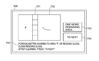
- FIGS. 7A and 7B show an example of data display provided on the operation panel 306 in step S 410 of the foreign matter detection handling process shown in FIGS. 4A and 4B .
- the operation panel 306 of the image reading apparatus of this embodiment has a display part constituted by a touch panel that is capable of displaying various information and capable of enabling the user to operate various parts of the image reading apparatus.
- On the display part of the operation panel 306 there can be displayed display fields 701 - 705 for displaying main scanning index plate image data, enlarged image data of foreign matter area, the number of uncleaned foreign matter areas, an operation button, and a message for prompting cleaning, respectively.
- the number of uncleaned foreign matter areas represents a number of remaining foreign matter areas for which cleaning is not completed.
- a “to next” button is displayed as shown in FIG. 7A , if the number of uncleaned foreign matter areas is not equal to zero, whereas a cleaning completion button is displayed as shown in FIG. 7B , if the number of uncleaned foreign matter areas is zero.
- FIG. 8 shows in flowchart the procedures of a cleaning operation performed by a user.
- the user confirms main scanning index plate image data as position information and enlarged image data of foreign matter area that are displayed in the display fields 701 , 702 of the operation panel 306 (step S 801 ), and cleans the foreign matter area on the reading glass 116 (step S 802 ).
- the user presses the button displayed in the operation button display field 704 (step S 803 ).
- step S 804 the user confirms whether or not the number of uncleaned foreign matter areas displayed in the display field 703 is equal to zero, thereby determining whether or not a remaining uncleaned foreign matter is present. If the number of uncleaned foreign matter areas is zero (YES to step S 804 ), the user completes the cleaning operation. On the other hand, if the number of uncleaned foreign matter areas is not equal to zero (NO to step S 804 ), the user returns to step S 801 to continue the cleaning operation.
- the presence or absence of foreign matter on at least the surface of the reading glass 116 is detected when the reading of originals in flow-reading mode is started in response to a reading start signal input from the operation panel 306 .
- a reading signal which is image data in the reading range in flow reading that is set along the main scanning direction, is output from the line sensor 123 .
- a brightness value of the image data is compared with a predetermined brightness value on a per pixel basis, thereby detecting the presence or absence of foreign matter at each pixel of the image data.
- a main scanning direction area where the foreign matter is present is identified based on a pixel position of the image data where the foreign matter is detected.
- a part, either the reading glass 116 or the conveyance roller 112 , to which the foreign matter is adhered is determined. If a continuous streak is present in the image data, it is determined that the foreign matter is adhered to the surface of the reading glass 116 . On the other hand, if an intermittent streak is present in the image data, it is determined that the foreign matter is adhered to the conveyance roller 112 .
- a portion of the surface of the reading glass 116 corresponding to the reading position in flow reading is read by the reading unit 125 in the fixed-reading mode. Then, based on the image data read by the reading unit 125 , enlarged bitmap image data of foreign matter area is generated. Furthermore, from foreign matter position data, a corresponding position on the main scanning index plate 201 is calculated, and main scanning index plate image data is generated.
- the main scanning index plate image data, the enlarged image data of foreign matter area, the number of uncleaned foreign matter areas, the operation button, and the message for prompting cleaning are displayed in the display fields 701 - 705 of the operation panel 306 .
- the user can quickly visually recognize the position and shape of the foreign matter and can easily perform a foreign matter cleaning operation.
- the image reading apparatus of this embodiment is configured to detect whether or not foreign matter is present when an original image is read in the fixed-reading mode.
- the area of the reading glass 116 for which the foreign matter detection is to be performed becomes large. Accordingly, the productivity is noticeably lowered, if the foreign matter detection is automatically performed each time an original image is read.
- the image reading apparatus of this embodiment is configured to perform the foreign matter detection when a cleaning mode is selected by the user.
- the image reading apparatus of this embodiment is the same in basic construction as that of the first embodiment, and a description thereof will be omitted.
- FIG. 9 shows in plan view a main scanning index plate and a sub-scanning index plate that are provided in the image reading apparatus of this embodiment.
- the main scanning index plate 201 is disposed along the short edge of the reading glass 116 on the side close to the reading position in flow reading and extends in the main scanning direction, as in the first embodiment.
- a sub-scanning index plate 901 is disposed adjacent to a long edge of the reading glass 116 and extends in the sub-scanning direction.
- the sub-scanning index plate 901 is provided with main scales that equally divide the entire sub-scanning direction area of the reading glass 116 into a plurality of (e.g., fourteen) second partial areas and auxiliary scales that subdivide the partial areas. It should be noted that a position index array (e.g., main and auxiliary scales) can be formed on the reading glass 116 instead of providing the main scanning index plate 201 and the sub-scanning index plate 901 .
- a position index array e.g., main and auxiliary scales
- FIGS. 10A and 10B show in flowchart the procedures of a cleaning mode process executed by the CPU 302 of the image reading apparatus of the second embodiment.
- the CPU 302 determines whether or not it detects a cleaning start signal supplied from the operation panel 306 (step S 1001 ).
- the CPU 302 When detecting the cleaning start signal (YES to step S 1001 ), the CPU 302 supplies a control signal to the reading unit controller 304 to move the reading unit 125 , inputs a read signal from the A/D converter 301 to acquire image data of the surface of the reading glass 116 that is read by the reading unit 125 in the fixed-reading mode, and stores the acquired image data into the RAM 303 (step S 1002 ).
- the CPU 302 sequentially reads the image data stored in the RAM 303 , performs a foreign matter detection process based on the image data (step S 1003 ), and determines whether or not there is foreign matter on the surface of the reading glass 116 (step S 1004 ). If there is no foreign matter on the surface of the reading glass 116 (NO to step S 1004 ), the CPU 302 causes the operation panel 306 to display on its display part a message stating that no foreign matter has been detected (step S 1014 ), and completes the present process.
- step S 1004 the CPU 302 performs a position data storage process for storing relevant position data into the RAM 303 according to procedures shown in FIG. 11 . Furthermore, the CPU 302 causes the operation panel 306 to display on its display part a message stating that foreign matter has been detected (step S 1005 ), and initializes the cleaning number-of-times counter (step S 1006 ).
- the CPU 302 reads from the RAM 303 foreign matter position data and the image data (which is read in step S 1002 ), and generates enlarged bitmap image data of foreign matter area. Furthermore, as in the first embodiment, the CPU 302 calculates a main scanning direction position and a sub-scanning direction position of the foreign matter from the foreign matter position data, and generates index plate image data that is position information to be displayed on the display part of the operation panel 306 (step S 1007 ).
- the CPU 302 causes the operation panel 306 to display a message for prompting cleaning and to display the enlarged bitmap image data of foreign matter area and the index plate image data that are generated in step S 1007 as exemplarily shown in FIG. 12A or 12 B (step S 1008 ). Then, the CPU 302 determines whether or not it detects a cleaning completion signal supplied from the operation panel 306 (step S 1009 ).
- the CPU 302 When detecting the cleaning completion signal, the CPU 302 causes the reading unit 125 to read the surface of the reading glass 116 (step S 1010 ), performs a foreign matter detection process (step S 1011 ), and determines whether or not foreign matter has been detected (step S 1012 ).
- step S 1012 If foreign matter has not been detected (NO to step S 1012 ), the CPU 302 causes the operation panel 306 to display a message stating that cleaning has normally been completed (step S 1013 ), and completes the cleaning mode process.
- step S 1012 the CPU 302 determines whether or not a value of the cleaning number-of-times counter is equal to or larger than a predetermined value (step S 1015 ). If the value of the cleaning number-of-times counter is equal to or larger than the predetermined value (YES to step S 1015 ), the CPU 302 determines that foreign matter cannot be removed even if the reading glass cleaning operation will be repeated, causes the operation panel 306 to display abnormal completion, and stops operations of respective parts of the apparatus (step S 1016 ). Then, the cleaning mode process is completed.
- step S 1015 if the value of the cleaning number-of-times counter is smaller than the predetermined value (NO to step S 1015 ), the CPU 302 adds 1 to the value of the cleaning number-of-times counter (step S 1017 ), and returns to step S 1007 .
- the message for prompting cleaning is repeatedly displayed until foreign matter becomes undetected or until the number of times of cleaning reaches a predetermined number of times.
- FIG. 11 shows in flowchart the procedures of the position data storage process executed in step S 1005 of the cleaning mode process shown in FIGS. 10A and 10B .
- the CPU 302 reads image data from the RAM 303 pixel by pixel (step S 1101 ), and determines whether or not a brightness value of the read image data is equal to or smaller than a predetermined brightness value (step S 1102 ).
- the predetermined brightness value is determined in advance based on a brightness value obtained when a white color platen (not shown) is read, which is disposed at a bottom face of the ADF 102 so as to face the reading glass 116 .
- step S 1101 If the brightness value of the image data read in step S 1101 is larger than the predetermined brightness value, the CPU 302 determines that there is no foreign matter and proceeds to step S 1104 .
- the CPU 302 determines that there is foreign matter and records, into the RAM 303 , position information indicating a position where the foreign matter is present (step S 1103 ), and determines whether or not the current pixel of the image data is the last pixel (step S 1104 ).
- step S 1104 If determined that the image data has not been read to the end (NO to step S 1104 ), the flow returns to step S 1101 . On the other hand, if determined that the image data has been read to the end (YES to step S 1140 ), the position data storage process is completed.
- FIGS. 12A and 12B show an example of display of a message and data provided on the operation panel 306 in step S 1008 of the cleaning mode process shown in FIGS. 10A and 10B .
- the operation panel 306 of the first embodiment has the display fields 701 - 705 as shown in FIGS. 7A and 7B , and main scanning index plate image data is displayed in the display field 701 .
- the operation panel 306 of this embodiment has the display fields 1201 and 702 - 705 , and main scanning index plate image data and sub-scanning index plate image data, which are position information, are displayed in the display field 1201 .
- this embodiment is basically the same in construction, function, and advantage as those of the first embodiment.
- foreign matter detection is performed when the cleaning mode is selected, and one or more foreign matter areas on the surface of the reading glass 116 are identified two-dimensionally.
- the surface of the reading glass 116 is read by the reading unit 125 in the fixed-reading mode to thereby obtain image data. Then, a brightness value of each pixel of the image data is compared with the predetermined brightness value that corresponds to a brightness value obtained when the white color platen is read, whereby the presence or absence of foreign matter on the surface of the reading glass 116 is detected.
- a main scanning direction area where the foreign matter is present is identified based on a pixel position of the image data where the foreign matter is detected, and a sub-scanning direction area where the foreign matter is present is identified based on a moving position of the reading unit 125 at a timing where the foreign matter is detected.
- the reading glass 116 is read by the reading unit 125 , and enlarged bitmap image data of foreign matter area is generated based on the resultant image data. Furthermore, from foreign matter position data, a corresponding position on the main scanning index plate 201 and a corresponding position on the sub-scanning index plate 901 are calculated, and image data of the scanning index plates is generated.
- the image data of the scanning index plates, the enlarged image data of foreign matter, the number of uncleaned foreign matter areas, the operation button, and the message for prompting cleaning are displayed in the display fields 1201 and 702 - 705 of the operation panel 306 .
- position indexes that respectively indicate the main scanning direction area and the sub-scanning direction area where the foreign matter is present are displayed, whereby the foreign matter area is indicated two-dimensionally.
Abstract
Description
Tv=(0.0254/Fv)÷Rv (1)
Mv=(Lv/Fv)÷Tv (2)
ΔNh=Nh÷(Ds×Dm) (3)
Xp÷(ΔNh×Dm) (4)
R÷(ΔNh×Ds) (5)
Ah=Ny÷(5×ΔNh)=Ahn÷Ahd (6)
Claims (14)
Applications Claiming Priority (2)
| Application Number | Priority Date | Filing Date | Title |
|---|---|---|---|
| JP2013-009252 | 2013-01-22 | ||
| JP2013009252A JP2014143483A (en) | 2013-01-22 | 2013-01-22 | Image reading device |
Publications (2)
| Publication Number | Publication Date |
|---|---|
| US20140204433A1 US20140204433A1 (en) | 2014-07-24 |
| US9219837B2 true US9219837B2 (en) | 2015-12-22 |
Family
ID=51207471
Family Applications (1)
| Application Number | Title | Priority Date | Filing Date |
|---|---|---|---|
| US14/154,254 Expired - Fee Related US9219837B2 (en) | 2013-01-22 | 2014-01-14 | Image reading apparatus capable of displaying foreign matter position as image |
Country Status (2)
| Country | Link |
|---|---|
| US (1) | US9219837B2 (en) |
| JP (1) | JP2014143483A (en) |
Cited By (2)
| Publication number | Priority date | Publication date | Assignee | Title |
|---|---|---|---|---|
| US20160248920A1 (en) * | 2015-02-23 | 2016-08-25 | Canon Kabushiki Kaisha | Image reading apparatus with reading position determination unit that determines reading position for original |
| US20190268590A1 (en) * | 2018-02-28 | 2019-08-29 | Panasonic Liquid Crystal Display Co., Ltd. | Calibration system for display device, display device, image capturing device, server and calibration method for display device |
Families Citing this family (6)
| Publication number | Priority date | Publication date | Assignee | Title |
|---|---|---|---|---|
| JP2015198327A (en) * | 2014-04-01 | 2015-11-09 | キヤノン株式会社 | Image reading device, image reading method, and computer program |
| JP6478641B2 (en) * | 2015-01-08 | 2019-03-06 | キヤノン株式会社 | Image processing apparatus, information processing method, and program |
| US9378440B1 (en) * | 2015-03-30 | 2016-06-28 | Xerox Corporation | System and method for reducing toner contamination on roll pair of an image forming apparatus |
| JP2017122785A (en) * | 2016-01-06 | 2017-07-13 | 富士ゼロックス株式会社 | Image forming apparatus |
| JP2021190927A (en) * | 2020-06-02 | 2021-12-13 | 株式会社リコー | Touch panel device, image forming apparatus, and mode control program |
| CN113592728B (en) * | 2021-07-01 | 2024-04-05 | 温州理工学院 | Image restoration method, system, processing terminal and computer medium |
Citations (10)
| Publication number | Priority date | Publication date | Assignee | Title |
|---|---|---|---|---|
| US5084760A (en) * | 1988-02-01 | 1992-01-28 | Minolta Camera Kabushiki Kaisha | Copying machine providing copy paper corresponding to read image area |
| US20020071135A1 (en) * | 2000-12-12 | 2002-06-13 | Shoji Takeda | Dust and dirt detection in image reading apparatus having original flow scanning function |
| US6750990B1 (en) * | 1999-11-16 | 2004-06-15 | Canon Kabushiki Kaisha | Image scanning apparatus, image forming apparatus, image forming system, image scanning control method, and storage medium |
| US20040125412A1 (en) * | 2002-11-22 | 2004-07-01 | Canon Kabushiki Kaisha | Image reading apparatus |
| US6792161B1 (en) * | 1998-07-31 | 2004-09-14 | Minolta Co., Ltd. | Image input device with dust detector |
| US20060061830A1 (en) * | 2004-09-21 | 2006-03-23 | Kabushiki Kaisha Toshiba | Image reading apparatus |
| US20090066831A1 (en) * | 2007-09-12 | 2009-03-12 | Canon Kabushiki Kaisha | Image capturing apparatus, method of controlling the same, and program |
| US20100020369A1 (en) * | 2008-07-25 | 2010-01-28 | Kyocera Mita Corporation | Image reading device and image forming apparatus |
| US7719726B2 (en) | 2005-10-05 | 2010-05-18 | Canon Kabushiki Kaisha | Image reading apparatus and method of displaying alien substance location thereof |
| US20140177016A1 (en) * | 2012-12-20 | 2014-06-26 | Xerox Corporation | Systems and methods for streak detection in image array scanning |
-
2013
- 2013-01-22 JP JP2013009252A patent/JP2014143483A/en active Pending
-
2014
- 2014-01-14 US US14/154,254 patent/US9219837B2/en not_active Expired - Fee Related
Patent Citations (10)
| Publication number | Priority date | Publication date | Assignee | Title |
|---|---|---|---|---|
| US5084760A (en) * | 1988-02-01 | 1992-01-28 | Minolta Camera Kabushiki Kaisha | Copying machine providing copy paper corresponding to read image area |
| US6792161B1 (en) * | 1998-07-31 | 2004-09-14 | Minolta Co., Ltd. | Image input device with dust detector |
| US6750990B1 (en) * | 1999-11-16 | 2004-06-15 | Canon Kabushiki Kaisha | Image scanning apparatus, image forming apparatus, image forming system, image scanning control method, and storage medium |
| US20020071135A1 (en) * | 2000-12-12 | 2002-06-13 | Shoji Takeda | Dust and dirt detection in image reading apparatus having original flow scanning function |
| US20040125412A1 (en) * | 2002-11-22 | 2004-07-01 | Canon Kabushiki Kaisha | Image reading apparatus |
| US20060061830A1 (en) * | 2004-09-21 | 2006-03-23 | Kabushiki Kaisha Toshiba | Image reading apparatus |
| US7719726B2 (en) | 2005-10-05 | 2010-05-18 | Canon Kabushiki Kaisha | Image reading apparatus and method of displaying alien substance location thereof |
| US20090066831A1 (en) * | 2007-09-12 | 2009-03-12 | Canon Kabushiki Kaisha | Image capturing apparatus, method of controlling the same, and program |
| US20100020369A1 (en) * | 2008-07-25 | 2010-01-28 | Kyocera Mita Corporation | Image reading device and image forming apparatus |
| US20140177016A1 (en) * | 2012-12-20 | 2014-06-26 | Xerox Corporation | Systems and methods for streak detection in image array scanning |
Cited By (3)
| Publication number | Priority date | Publication date | Assignee | Title |
|---|---|---|---|---|
| US20160248920A1 (en) * | 2015-02-23 | 2016-08-25 | Canon Kabushiki Kaisha | Image reading apparatus with reading position determination unit that determines reading position for original |
| US9706062B2 (en) * | 2015-02-23 | 2017-07-11 | Canon Kabushiki Kaisha | Image reading apparatus with reading position determination unit that determines reading position for original |
| US20190268590A1 (en) * | 2018-02-28 | 2019-08-29 | Panasonic Liquid Crystal Display Co., Ltd. | Calibration system for display device, display device, image capturing device, server and calibration method for display device |
Also Published As
| Publication number | Publication date |
|---|---|
| JP2014143483A (en) | 2014-08-07 |
| US20140204433A1 (en) | 2014-07-24 |
Similar Documents
| Publication | Publication Date | Title |
|---|---|---|
| US9219837B2 (en) | Image reading apparatus capable of displaying foreign matter position as image | |
| US10356252B2 (en) | Image reading apparatus, image forming apparatus, image reading method, and non-transitory storage medium that generate abnormal pixel information based on received information | |
| JP6849322B2 (en) | Image reader, image forming device | |
| US8810823B2 (en) | Image reading device, an image forming apparatus, and methods for detecting dirt in document reading positions | |
| US8837018B2 (en) | Image scanning apparatus scanning document image and image forming apparatus including image scanning apparatus | |
| US20130003147A1 (en) | Image scanner, image forming apparatus and dew-condensation determination method | |
| EP2323364A2 (en) | Image scanning apparatus and image forming apparatus | |
| JP2004173165A (en) | Image reader | |
| JP2017118169A (en) | Image reader and image formation apparatus | |
| US10389911B2 (en) | Original reading apparatus | |
| JP2012054834A (en) | Image reader and image formation apparatus with the same | |
| US11825038B2 (en) | Reading apparatus and image forming system for outputting maintenance information | |
| JP2010187080A (en) | Image reader | |
| JP5255891B2 (en) | Image reading device | |
| JP6680110B2 (en) | Image reading apparatus and image forming apparatus | |
| US9699327B2 (en) | Image reading apparatus capable of determining reading position less affected by foreign matter | |
| JP2011234129A (en) | Original image reading apparatus and image forming apparatus | |
| US10009494B2 (en) | Image reading apparatus with end detection and image reading method | |
| JP4528319B2 (en) | Document reader | |
| US9706062B2 (en) | Image reading apparatus with reading position determination unit that determines reading position for original | |
| JP5663690B2 (en) | Image reading apparatus and image forming apparatus | |
| JP2009159215A (en) | Image reader | |
| JP2020156055A (en) | Image processing apparatus and blank paper document determination method | |
| JP2010219773A (en) | Image reader and image forming device | |
| JP2014057193A (en) | Image reading device and cleaning support method |
Legal Events
| Date | Code | Title | Description |
|---|---|---|---|
| AS | Assignment |
Owner name: CANON KABUSHIKI KAISHA, JAPAN Free format text: ASSIGNMENT OF ASSIGNORS INTEREST;ASSIGNOR:KOYAMA, HAYATO;REEL/FRAME:032731/0930 Effective date: 20140106 |
|
| STCF | Information on status: patent grant |
Free format text: PATENTED CASE |
|
| MAFP | Maintenance fee payment |
Free format text: PAYMENT OF MAINTENANCE FEE, 4TH YEAR, LARGE ENTITY (ORIGINAL EVENT CODE: M1551); ENTITY STATUS OF PATENT OWNER: LARGE ENTITY Year of fee payment: 4 |
|
| FEPP | Fee payment procedure |
Free format text: MAINTENANCE FEE REMINDER MAILED (ORIGINAL EVENT CODE: REM.); ENTITY STATUS OF PATENT OWNER: LARGE ENTITY |
|
| LAPS | Lapse for failure to pay maintenance fees |
Free format text: PATENT EXPIRED FOR FAILURE TO PAY MAINTENANCE FEES (ORIGINAL EVENT CODE: EXP.); ENTITY STATUS OF PATENT OWNER: LARGE ENTITY |
|
| STCH | Information on status: patent discontinuation |
Free format text: PATENT EXPIRED DUE TO NONPAYMENT OF MAINTENANCE FEES UNDER 37 CFR 1.362 |
|
| FP | Lapsed due to failure to pay maintenance fee |
Effective date: 20231222 |