US9218696B2 - Wireless access control system and related methods - Google Patents

Wireless access control system and related methods Download PDF

Info

Publication number
US9218696B2
US9218696B2 US14/681,243 US201514681243A US9218696B2 US 9218696 B2 US9218696 B2 US 9218696B2 US 201514681243 A US201514681243 A US 201514681243A US 9218696 B2 US9218696 B2 US 9218696B2
Authority
US
United States
Prior art keywords
lock
remote access
area
controller
access device
Prior art date
Legal status (The legal status is an assumption and is not a legal conclusion. Google has not performed a legal analysis and makes no representation as to the accuracy of the status listed.)
Active
Application number
US14/681,243
Other versions
US20150213663A1 (en
Inventor
Philip C. Dumas
Thomas Bennett
Current Assignee (The listed assignees may be inaccurate. Google has not performed a legal analysis and makes no representation or warranty as to the accuracy of the list.)
Unikey Technnologies Inc
Original Assignee
Unikey Technnologies Inc
Priority date (The priority date is an assumption and is not a legal conclusion. Google has not performed a legal analysis and makes no representation as to the accuracy of the date listed.)
Filing date
Publication date
Family has litigation
First worldwide family litigation filed litigation Critical https://patents.darts-ip.com/?family=48743508&utm_source=google_patent&utm_medium=platform_link&utm_campaign=public_patent_search&patent=US9218696(B2) "Global patent litigation dataset” by Darts-ip is licensed under a Creative Commons Attribution 4.0 International License.
Priority claimed from US13/415,365 external-priority patent/US9336637B2/en
Priority claimed from US13/654,132 external-priority patent/US9196104B2/en
Application filed by Unikey Technnologies Inc filed Critical Unikey Technnologies Inc
Priority to US14/681,243 priority Critical patent/US9218696B2/en
Assigned to UNIKEY TECHNOLOGIES, INC. reassignment UNIKEY TECHNOLOGIES, INC. ASSIGNMENT OF ASSIGNORS INTEREST (SEE DOCUMENT FOR DETAILS). Assignors: BENNETT, THOMAS, DUMAS, PHILIP C.
Publication of US20150213663A1 publication Critical patent/US20150213663A1/en
Application granted granted Critical
Publication of US9218696B2 publication Critical patent/US9218696B2/en
Assigned to WESTERN ALLIANCE BANK reassignment WESTERN ALLIANCE BANK INTELLECTUAL PROPERTY SECURITY AGREEMENT Assignors: UNIKEY TECHNOLOGIES INC.
Active legal-status Critical Current
Anticipated expiration legal-status Critical

Links

Images

Classifications

    • GPHYSICS
    • G07CHECKING-DEVICES
    • G07CTIME OR ATTENDANCE REGISTERS; REGISTERING OR INDICATING THE WORKING OF MACHINES; GENERATING RANDOM NUMBERS; VOTING OR LOTTERY APPARATUS; ARRANGEMENTS, SYSTEMS OR APPARATUS FOR CHECKING NOT PROVIDED FOR ELSEWHERE
    • G07C9/00Individual registration on entry or exit
    • G07C9/20Individual registration on entry or exit involving the use of a pass
    • G07C9/21Individual registration on entry or exit involving the use of a pass having a variable access code
    • G07C9/00015
    • GPHYSICS
    • G07CHECKING-DEVICES
    • G07CTIME OR ATTENDANCE REGISTERS; REGISTERING OR INDICATING THE WORKING OF MACHINES; GENERATING RANDOM NUMBERS; VOTING OR LOTTERY APPARATUS; ARRANGEMENTS, SYSTEMS OR APPARATUS FOR CHECKING NOT PROVIDED FOR ELSEWHERE
    • G07C9/00Individual registration on entry or exit
    • G07C9/20Individual registration on entry or exit involving the use of a pass
    • G07C9/27Individual registration on entry or exit involving the use of a pass with central registration
    • EFIXED CONSTRUCTIONS
    • E05LOCKS; KEYS; WINDOW OR DOOR FITTINGS; SAFES
    • E05BLOCKS; ACCESSORIES THEREFOR; HANDCUFFS
    • E05B47/00Operating or controlling locks or other fastening devices by electric or magnetic means
    • G07C9/00103
    • G07C9/00111
    • GPHYSICS
    • G07CHECKING-DEVICES
    • G07CTIME OR ATTENDANCE REGISTERS; REGISTERING OR INDICATING THE WORKING OF MACHINES; GENERATING RANDOM NUMBERS; VOTING OR LOTTERY APPARATUS; ARRANGEMENTS, SYSTEMS OR APPARATUS FOR CHECKING NOT PROVIDED FOR ELSEWHERE
    • G07C9/00Individual registration on entry or exit
    • G07C9/00174Electronically operated locks; Circuits therefor; Nonmechanical keys therefor, e.g. passive or active electrical keys or other data carriers without mechanical keys
    • G07C9/00182Electronically operated locks; Circuits therefor; Nonmechanical keys therefor, e.g. passive or active electrical keys or other data carriers without mechanical keys operated with unidirectional data transmission between data carrier and locks
    • GPHYSICS
    • G07CHECKING-DEVICES
    • G07CTIME OR ATTENDANCE REGISTERS; REGISTERING OR INDICATING THE WORKING OF MACHINES; GENERATING RANDOM NUMBERS; VOTING OR LOTTERY APPARATUS; ARRANGEMENTS, SYSTEMS OR APPARATUS FOR CHECKING NOT PROVIDED FOR ELSEWHERE
    • G07C9/00Individual registration on entry or exit
    • G07C9/00174Electronically operated locks; Circuits therefor; Nonmechanical keys therefor, e.g. passive or active electrical keys or other data carriers without mechanical keys
    • G07C9/00309Electronically operated locks; Circuits therefor; Nonmechanical keys therefor, e.g. passive or active electrical keys or other data carriers without mechanical keys operated with bidirectional data transmission between data carrier and locks
    • GPHYSICS
    • G07CHECKING-DEVICES
    • G07CTIME OR ATTENDANCE REGISTERS; REGISTERING OR INDICATING THE WORKING OF MACHINES; GENERATING RANDOM NUMBERS; VOTING OR LOTTERY APPARATUS; ARRANGEMENTS, SYSTEMS OR APPARATUS FOR CHECKING NOT PROVIDED FOR ELSEWHERE
    • G07C9/00Individual registration on entry or exit
    • G07C9/00174Electronically operated locks; Circuits therefor; Nonmechanical keys therefor, e.g. passive or active electrical keys or other data carriers without mechanical keys
    • G07C9/00571Electronically operated locks; Circuits therefor; Nonmechanical keys therefor, e.g. passive or active electrical keys or other data carriers without mechanical keys operated by interacting with a central unit
    • GPHYSICS
    • G07CHECKING-DEVICES
    • G07CTIME OR ATTENDANCE REGISTERS; REGISTERING OR INDICATING THE WORKING OF MACHINES; GENERATING RANDOM NUMBERS; VOTING OR LOTTERY APPARATUS; ARRANGEMENTS, SYSTEMS OR APPARATUS FOR CHECKING NOT PROVIDED FOR ELSEWHERE
    • G07C9/00Individual registration on entry or exit
    • G07C9/20Individual registration on entry or exit involving the use of a pass
    • G07C9/28Individual registration on entry or exit involving the use of a pass the pass enabling tracking or indicating presence
    • GPHYSICS
    • G07CHECKING-DEVICES
    • G07CTIME OR ATTENDANCE REGISTERS; REGISTERING OR INDICATING THE WORKING OF MACHINES; GENERATING RANDOM NUMBERS; VOTING OR LOTTERY APPARATUS; ARRANGEMENTS, SYSTEMS OR APPARATUS FOR CHECKING NOT PROVIDED FOR ELSEWHERE
    • G07C9/00Individual registration on entry or exit
    • G07C9/00174Electronically operated locks; Circuits therefor; Nonmechanical keys therefor, e.g. passive or active electrical keys or other data carriers without mechanical keys
    • G07C2009/00753Electronically operated locks; Circuits therefor; Nonmechanical keys therefor, e.g. passive or active electrical keys or other data carriers without mechanical keys operated by active electrical keys
    • G07C2009/00769Electronically operated locks; Circuits therefor; Nonmechanical keys therefor, e.g. passive or active electrical keys or other data carriers without mechanical keys operated by active electrical keys with data transmission performed by wireless means
    • G07C2009/00793Electronically operated locks; Circuits therefor; Nonmechanical keys therefor, e.g. passive or active electrical keys or other data carriers without mechanical keys operated by active electrical keys with data transmission performed by wireless means by Hertzian waves
    • GPHYSICS
    • G07CHECKING-DEVICES
    • G07CTIME OR ATTENDANCE REGISTERS; REGISTERING OR INDICATING THE WORKING OF MACHINES; GENERATING RANDOM NUMBERS; VOTING OR LOTTERY APPARATUS; ARRANGEMENTS, SYSTEMS OR APPARATUS FOR CHECKING NOT PROVIDED FOR ELSEWHERE
    • G07C2209/00Indexing scheme relating to groups G07C9/00 - G07C9/38
    • G07C2209/04Access control involving a hierarchy in access rights
    • GPHYSICS
    • G07CHECKING-DEVICES
    • G07CTIME OR ATTENDANCE REGISTERS; REGISTERING OR INDICATING THE WORKING OF MACHINES; GENERATING RANDOM NUMBERS; VOTING OR LOTTERY APPARATUS; ARRANGEMENTS, SYSTEMS OR APPARATUS FOR CHECKING NOT PROVIDED FOR ELSEWHERE
    • G07C2209/00Indexing scheme relating to groups G07C9/00 - G07C9/38
    • G07C2209/60Indexing scheme relating to groups G07C9/00174 - G07C9/00944
    • G07C2209/63Comprising locating means for detecting the position of the data carrier, i.e. within the vehicle or within a certain distance from the vehicle
    • G07C2209/64Comprising locating means for detecting the position of the data carrier, i.e. within the vehicle or within a certain distance from the vehicle using a proximity sensor

Definitions

  • the present invention generally relates to access control systems, and more particularly, to wireless access control systems for door locks.
  • a passive keyless entry (PKE) system offers an increased level of convenience over a standard lock and key, for example, by providing the ability to access a secure building or device without having to find, insert, and turn a traditional key. A user may simply approach and touch a locked PKE lock and with little if any pause, the lock grants this user access if they are carrying an authorized token.
  • PKE passive keyless entry
  • a PKE system is currently used in an automotive application and may offer increased convenience by identifying drivers and unlocking the car as they approach and grab the handle. Automotive access is traditionally given by inserting a key into the lock or by pushing buttons on a traditional remote keyless entry (RKE) system. In contrast, a PKE system grants access with reduced user interaction through the use of a hands free token carried by the driver.
  • RKE remote keyless entry
  • the desired basic perceived behavior of the PKE system in a residential application may be as follows: 1) the user approaches and touches the lock; 2) the lock authenticates the user with a minimally perceived delay; 3) the lock unlocks; 4) the lock may not operate if the authorized user is outside a desired range and the lock is touched by another, unauthorized, user; 5) the lock may not operate if the authorized user is on the inside of the house, and the lock is touched on the outside by an unauthorized user; and 6) the battery powered lock needs several months or more worth of battery life to prevent inconvenient and costly battery changes. 7) if a PKE fob is used, battery power needs to be over a year. 8) the lock can provide anytime, or configurable limited time, access control. 9) the lock has the ability to be locked without a remote access device
  • a wireless access control system includes a remote access device for authorizing access control to a lock when present on a user who touches, or triggers a proximity detector, of the lock.
  • a wireless access control system includes a remote access device for authorizing access control to a lock when the user possessing the authorized remote access device is within an activation range of the lock and door. If the authorized user is outside of activation range, signal range, or inside the lock and door, the remote access device will not be enabled to lock or unlock the door.
  • the remote access device can be a Smartphone.
  • additional haptic feedback can be utilized to control the electronic lock. A user can tap the remote access device if within activation range to cause a larger acceleration trigger which can be captured by the controller and sent to the lock via a radio signal to lock or unlock the electronic lock in response.
  • a lock in another embodiment, includes a controller and radio signal transceiver to communicate with an electronic lock for controlling the electronic lock in response to the signal from the remote access device.
  • the lock includes an accelerometer for determining movement, such as a knock or the door opening, in which the lock is disposed and controlling the radio or the electronic lock via the controller as a function of the acceleration signal.
  • a real time clock provides a clock input to the controller, the controller allowing for configurable access control of the electronic lock as a function of the time indicated by a signal from the real time clock.
  • the controller operating on the real time clock signal can permit anytime, limited time, recurring time windows, or one-time use access for example.
  • a proximity detector which detects the presence of a user at or near the lock provides a proximity detection signal to the controller and radio for permitting control of the electronic lock in response to a signal from a remote access device when the proximity of a user is detected.
  • the proximity detector may be a touch sensor disposed within the lock or a trip light detector.
  • the trip light detector is located at the bottom of a deadbolt lock facing downwards towards the handle so when a user grabs the handle of the door the light detector is tripped and the deadbolt controller can initiate the desired action, for example unlocking the deadbolt.
  • the proximity detector can be intentionally triggered “n” times in a row within a predetermined time period, or be continuously held for a predetermined time period (the time period preferably being ten or fewer seconds) to trigger a lock event without a remote access device being present.
  • the proximity detector which detects the presence of a user at or near the lock provides a proximity detection signal to the controller and radio to turn on or change the state of the radio in order to make a connection with an authorized remote access device and lock or unlock the electronic lock.
  • the proximity detection activates the radio into a listening state for a limited period of time to listen for remote access devices advertisements. This listening state requires more power there for it is desirable to only go into this state for a limited period of time upon user detection.
  • the lock is already communicating with an authorized remote access device and the proximity detector which detects the presence of a user at or near the lock provides a proximity detection signal to the controller to lock or unlock the electronic lock.
  • FIG. 1 is a schematic diagram of a wireless access system according to the present invention
  • FIG. 2 a is a perspective view of a lock constructed in accordance with the invention.
  • FIG. 2 b is a perspective view of a lock constructed in accordance with another embodiment of the invention.
  • FIG. 3 a is a top plan view of a remote access device constructed in accordance with the invention as a key;
  • FIG. 3 b is a front plan view of a remote access device constructed in accordance with yet another embodiment of the invention as an application for a cell phone;
  • FIG. 4 is a front plan view of a Router Plug-in Unit of the wireless access system constructed in accordance with the invention.
  • FIG. 5 is a schematic diagram of the communication between the components of the wireless access system in a typical residential system layout in accordance with the invention
  • FIG. 6 a - 6 d are a flow chart of operation of the wireless access system in accordance with the invention.
  • FIG. 7 a is a diagram of a system showing the local communication between the remote access and the lock in accordance with the invention.
  • FIG. 7 b is a diagram of a system showing range and location determination in accordance with the invention.
  • FIG. 8 is a diagram of a system showing the method of sending access control authorization from one remote access device to another in accordance with the invention.
  • FIG. 9 is a circuit diagram of a remote access device constructed in accordance with still another embodiment of the invention.
  • FIG. 10 is a circuit diagram of a PKE lock constructed in accordance with another embodiment of the invention.
  • FIG. 11 is a schematic diagram of a trip light circuit for sensing the presence of a user in accordance with the invention.
  • a wireless access system 10 for example, a PKE system, includes a lock 11 .
  • the lock 11 may be installed in a standard deadbolt hole and may be battery powered, for example.
  • the lock 11 may be a human controlled (keyed) lock, for example ( FIG. 2 a ).
  • the lock 11 includes an outer cylinder 12 that rotates freely around a standard key cylinder 13 . When engaged, the cylinder 13 is linked to a deadbolt 14 (which may optionally be part of lock 11 ), thus giving the user control to extend or retract the deadbolt utilizing their key.
  • the lock 11 includes a controller 21 or processor and wireless communication circuitry 22 for wireless communication which as will be discussed below, enable remote access device 15 to operate lock 11 .
  • the lock 11 ′ may be motor powered ( FIG. 2 b ).
  • the deadbolt 14 ′ is driven by the motor (not shown) to open the lock for authorized users having the remote access device 15 .
  • the lock 11 may be another type of lock or locking mechanism and may be installed in any access point, for example.
  • Lock 11 includes a proximity detector 27 for detecting the presence of a user.
  • Proximity detector 27 outputs a presence signal in response to detecting a user.
  • proximity detector 27 may be a capacitance touch sensor, a button, a trip light circuit, a near field detector, a radio frequency signal strength detector, an audio switch (which actuates upon receipt of audio signals of a set frequency), or the like.
  • Proximity detector 27 outputs the presence signal to controller 21 .
  • lock 11 is in a hibernation or low power level state.
  • controller 21 Upon triggering a proximity detector 27 outputting the presence signal by a users touch for example, controller 21 causes system 10 to wake up and start listening for remote access devices 15 advertisements.
  • the lock 11 Upon finding a remote access device 15 , the lock 11 communicates with (connects) to the remote access device 15 , determines if the device 15 is an authorized user via an encrypted key exchange, then determines if the remote access device 15 is in range to control the lock 11 , and ultimately provides access to an authorized user; all within a short or small perceived delayed time (ten seconds or less) if all the criteria is met.
  • the lock 11 may be advertising or listening (sending or sampling signals) at a low frequency rate in order to conserve battery power yet establish a communication link with the remote access device 15 in advance of a users touch. In this way, increasing the speed of the authentication process to create little if any perceived delay for the user.
  • the lock wireless communication circuitry 22 changes states and starts listening for a remote access device 15 advertisement.
  • a connection is made authentication can be done upon connection, or upon lock or unlock request from remote access device 15 .
  • the lock 11 tracks the Received Signal Strength Indicator (RSSI) of the remote access device until the algorithm determines it is within a defined accessible range from lock 11 .
  • the lock 11 gathers RSSI data and utilizes this data in an algorithm to determine the position of the remote access device 15 .
  • the lock grants remote access device 15 access control to lock or unlock the lock 11 .
  • Additional antennas may be used in some embodiments for more accurate position determining, and to increase authorized user capacity and overall speed of the wireless access system 10 .
  • the lock may be a doorknob lock, handle lock, or other style lock for example.
  • the wireless access system 10 includes a remote access device 15 .
  • the remote access device 15 is advantageously a key or token authorized to control the lock 11 .
  • the remote access device 15 may be a standard key including a controller 16 for controlling lock 11 via remote wireless access electronics coupled thereto ( FIG. 3 a ).
  • Remote access device 15 also includes wireless communication circuitry radio 18 such as a radio in one non-limiting embodiment, for sending and receiving signals.
  • the signal is a Bluetooth Low Energy signal.
  • the remote access device 15 may be a mobile wireless communications device, such as, for example, a Smartphone that may include the remote wireless access electronics described above cooperating with an application 17 ′ stored in memory 17 ( FIG. 3 b ).
  • the application 17 ′ may be configured to send a signal to provide access and control over the lock 11 ′, for example.
  • more than one remote access device 15 ′ may be used and may be another type of remote access wireless device, for example, a wireless FOB without the mechanical key, as will be appreciated by those skilled in the art.
  • the wireless access system 10 also includes a Router Plug-in Unit (RPU) 30 .
  • RPU Router Plug-in Unit
  • a controller 32 controls operation of RPU 30 .
  • the RPU 30 includes a radio transceiver 33 to communicate with lock 11 and/or remote access device 15 , and utilizes a Bluetooth Low Energy communication protocol to communicate with the lock 11 .
  • the RPU 30 may link to an off-site web-based server 34 via a communications network such as the internet 28 , for example.
  • a communications network such as the internet 28
  • the RPU 30 can send lock 11 status and transaction updates via the Internet 28 to the server 34 which can be viewed on a remote access device 15 or personal computer 25 , for example. Additional services may be selectively provided via the Internet using the connectivity of RPU 30 with server 34 , for example.
  • RPU 30 is described herein as a plugin device, it will be appreciated by those skilled in the art that the functionality of the RPU 30 may be embodied in any of a number of form factors, for example, such as a mobile cellular based unit making use of cell network 35 .
  • the RPU 30 is typically plugged-in to the mains power via power source plug-in 38 and to the internet 28 via the home router though an Ethernet cable and port 37 , at a location near the home router. RPU 30 may also communicate wirelessly to the lock 11 , which may be installed on the front door, for example.
  • the lock 11 may initially be in a low power mode in a step 101 to conserve battery power, for example.
  • the lock 11 is typically in a low power mode; searching for authorized remote access devices 15 ′, for example a Smartphone, at a lower frequency to conserve battery power.
  • the lock 11 when a user triggers the proximity detector 27 by touch in a Step 102 , or another method, the lock 11 begins to listen for remote access devices 15 in a Step 103 , more specifically fobs in this embodiment.
  • system 10 powers up and controller 2 increases its broadcast and listening rate.
  • lock 11 “sees” (receives) an advertisement from a fob 15 within a predetermined time period in a Step 104 , and the fob 15 is authorized for access at that time as determined by lock 11 in a step 107 , a connection is made between fob 15 and lock 11 in a step 110 . It is then determined whether fob 15 is still connected by determining whether communication has occurred within a predetermined time period in a Step 112 .
  • a lock 11 performs a challenge response verification process to authenticate the remote access device 15 . If fob 15 is verified by comparing an identification portion of the advertisement signal to information stored at system 10 , lock 11 begins to gather and process location and positioning data of fob 15 in a step 117 utilizing Received Signal Strength Indication (RSSI) by way of non-limiting example. Utilizing the location and positioning algorithm in step 117 , lock 11 can determine if the user is within activation range in step 118 .
  • RSSI Received Signal Strength Indication
  • step 118 If the user is in the activation range as determined in step 118 , the control of lock 11 is given to fob 15 and the lock 11 will lock or unlock as needed in a step 119 , then the lock 11 disconnects from fob 15 in a step 120 and returns to step 100 to its low power state 101 .
  • Step 104 If in Step 104 the advertisement from the fob 15 is not received within a predetermined time window or the fob is not authorized as determined in Steps 107 and a Step 109 in which the signal is ignored, or the fob connection times out in a Step 112 , or the challenge response in Step 115 is not an appropriate one, then the process returns to Step 100 to be repeated.
  • controller 21 can enable locking the door without the use of fob 15 . If proximity detector 27 , which may include a touch sensor, determines that lock 11 was touched at least a second time within a time window, preferably measured in seconds, in a Step 106 , then controller 21 determines whether lock 11 is unlocked in a step 108 . If it is determined that lock 11 is in fact unlocked in Step 108 , then it is determined whether or not or not the lock 11 is touched a third time within a predetermined time window measured in seconds or less, and if in fact the lock 11 is touched three times within the time window, then controller 21 causes lock 11 to lock bolt 14 in a Step 113 and the process is returned to the beginning in Step 100 to monitor for another remote access device 15 .
  • proximity detector 27 which may include a touch sensor
  • Step 106 and 111 If the deadbolt is not touched the prescribed number of times during the time window, in Steps 106 and 111 , or is already in the locked state as determined in Step 108 , then the process returns to Step 100 to await connection with another remote access device. In this way, a door can be locked merely by activating proximity detector 27 , a predetermined number of times within a predetermined time period, or by continuously activating proximity detector 27 for a predetermined time period.
  • the system may work without the need to touch lock 11 in step 102 .
  • lock 11 and remote access device 15 determine that they are within range of each other to begin processing without the need to initially touch lock 11 . This allows for the control of lock 11 well ahead of being sufficient proximity of a door to touch lock 11 .
  • an in-range remote access device 15 ′ such as a Smartphone responds in a Step 121 to a broadcast advertisement from the lock 11 in a Step 121 by controller 21 . If the Smartphone 15 ′ is authorized for access at that time as determined by controller 21 in a Step 122 , a connection is made in a Step 124 between a Smartphone 15 ′ and lock 11 . If Smartphone 15 ′ is authenticated during a challenge response verification process in Step 125 , lock 11 begins to gather and process location and positioning data in a Step 127 , utilizing RSSI or a signal from Global Positioning System (GPS) enabled Smartphone 15 , for example.
  • GPS Global Positioning System
  • the lock 11 can determine if the user is in activation range in a Step 129 .
  • lock 11 may determine whether lock 11 has been touched prior to determining whether the user is in range in Step 129 . If the user is in activation range, lock 11 will lock or unlock (reverse state) in a Step 130 .
  • information about remote access device 15 ′ may be stored at any one of memory 55 , and memory associated with personal computer 25 or server 34 .
  • Remote access device 15 may have limited access to lock 11 . By way of example, access may only be during predetermined time periods of a day, or for a limited number of times; such as a one-time use key. If the remote access device 15 ′, represents a one-time key as determined in Step 131 , this key will be deleted from the memory or stored in the memory of system 10 as an invalid key in Step 132 to prevent further access.
  • Step 125 the process is returned to Step 100 to begin again.
  • the button has not been pressed in Step 128 then the process merely returns to redetermining the location of remote access device 15 in Step 127 .
  • Step 105 once it is determined that the lock has been touched in Step 102 and lock 11 listens for a broadcast from fob 15 in Step 103 , if a lock 11 determines in a step 105 that a Smartphone connectable advertisement response has been received within a predetermined time window; five seconds or less in a preferred embodiment, the process continues for Smartphone 15 ′ at Step 124 as described above. If the response is not appropriate, as determined Step 105 , then the process returns to the beginning in Step 100 .
  • the location and positioning algorithm performed in a Step 127 can utilize RSSI in formation from the lock 11 to the remote access device 15 ′. This can be done by the remote access device 15 ′ receiving RSSI information from the lock 11 and transmitting this RSSI information back to the lock 11 to be processed by controller 21 for location and positioning purposes.
  • any unauthorized user can lock the lock 11 by triggering the proximity detector three consecutive times within a predetermined time window such as discussed above in Step 106 .
  • the lock 11 can be touched and held for greater than a predetermined time to lock the lock 11 .
  • only remote access devices 15 looking for a unique advertisement from the lock 11 will respond with a connectable advertisement. In this way, the system can provide access control to many possible authorized devices without adding additional delays per additional authorized devices.
  • the lock 11 may also request the user to verify their access control request by requiring the transmittal of a PIN, Password or other authentication code.
  • Lock 11 transmits a signal prompting the users, on their remote access device 15 ′, for example, via a display on their mobile wireless communications device to answer with a PIN.
  • Controller 21 compares the received password to authentication code previously stored by user at system 10 , prior to enabling control of lock 11 . This can be done to add additional security or to assist with inconclusive positioning or location information.
  • a user 70 carries a remote access device 15 ′, a Smartphone in their pocket for example. Assume the remote access device 15 ′ is positioned within in-signal range 90 . In this case, a wireless connection is made between the remote access device 15 ′ and the lock 11 . The remote access device 15 ′ is authorized to control the lock 11 .
  • the lock 11 when the user 70 approaches, their position is determined by receiving signals from remote access device 15 ′ at an exterior facing antenna 52 . Once user 10 is within activation range 91 , and touches the lock 11 , the lock 11 radio switches to an internal antenna 50 to verify the user 70 is on the outside. If the calibrated RSSI, as determined by controller 21 , or some other element of system 10 , from one or more readings from the internal antenna 50 is less than the external calibrated RSSI reading or readings, user 70 is determined by controller 21 to be on the outside and the lock 11 will lock or unlock. If the calibrated RSSI from the internal antenna 50 is greater than the RSSI reading or readings from external antenna 52 , user 70 is determined to be on the inside, within inside range 92 by controller 21 , and the lock 11 will not operate as to prevent unauthorized entry.
  • the wireless access system 10 may include a calibration feature. More particularly, a connection between the remote access device 15 ′ and the lock 11 may be used by the algorithm to calibrate the RSSI input to adjust for varying antenna characteristics of remote access devices 15 ′ or changes in user behavior or environmental conditions, for example.
  • the lock 11 determines RSSI values for remote access devices 15 ′ unlocking and locking events over a number of distinct communications. It then determines a maximum average activation range 91 value to calibrate with.
  • the lock 11 can request that the remote access device 15 ′ send its RSSI values as received from the lock 11 and utilize these to calibrate for remote access device 15 ′ antenna differences.
  • the calibration is continuously self-adjusting per the last “n” number of access control events as to adjust for user behavioral changes or local condition changes over time.
  • the wireless access system 10 may also include a computing device 25 , for example, a personal computer at the user's residence for use in a revocation process by way of example.
  • the computing device 25 may include circuitry for wirelessly communicating with the RPU 30 , remote access device 15 , and/or lock 11 for revoking a permission from remote access device 15 .
  • the computing device 25 may include Bluetooth Low Energy communications circuitry, for example. Other devices and communications protocols may be used in the revocation process.
  • wireless access system 10 is described herein with respect to a door, the wireless access system may be used for access control or protection of, but not limited to, appliances, a safe, heavy machinery, factory equipment, power tools, pad locks, real estate lock-boxes, garage door openers, etc., for example.
  • Alternative remote access device 15 embodiments may include a pen, watch, jewelry, headset, FDA, laptop, etc., for example.
  • the wireless access system 10 may be used to protect other devices or areas where it may be desired to restrict access.
  • the present invention lends itself to a process for transferring one-time, limited time, or permanent use Passive Keyless Entry (PKE) token key codes to a cellular or other wireless mobile remote access device 15 ′ for use with PKE access control devices, such as lock 11 for example.
  • PKE Passive Keyless Entry
  • FIG. 8 a first user has a first remote access device 15 ′ embodied in a mobile communication device that is PKE enabled and is known to lock 11 as an authorized user.
  • a second user has a second remote access device embodied in a mobile communication device 15 ′′ that is PKE enabled, but is not authorized for use with lock 11 .
  • Both users can communicate locally with lock 11 via a wireless Bluetooth Low Energy network as discussed above for example.
  • both users have the ability to communicate with each other via a cellular network 35 as known in the art, or other wireless communication and as a result have an almost unlimited range.
  • the authorized user of lock 11 chooses to send an unauthorized user an authorized token for the lock 11 by way of a mobile application 17 ′ on authorized remote access device 15 ′ to unauthorized remote access device 15 ′′.
  • the authorized user can select the option within mobile application 17 ′ on authorized remote access device 15 ′ for a one-time, limited time, or permanent token to send to unauthorized remote access device 15 ′′.
  • the authorization credentials are transmitted from the authorized remote access device 15 ′ to the currently unauthorized remote access device 15 ′′ via the cellular network 35 .
  • Now unauthorized remote access device 15 ′′ stores and makes use of the authorization credentials and becomes an authorized user of the lock 11 .
  • authorized remote access device 15 ′ sends a request for information to unauthorized remote access device 15 ′′ which responds to authorized remote access device with useful information such as device 15 ′′ Bluetooth address.
  • This information is then transmitted from authorized remote access device 15 ′ to the RPU 30 via the cellular network 35 to the internet, then from the internet to a home router 36 that is connected to the RPU 30 .
  • the RPU 30 then transfers identification information wirelessly to the lock 11 , so that when now authorized remote access device 15 ′′ tries to access the lock 11 , it is already a known remote access device, thus speeding up the initial access control process.
  • the key code can be sent directly to another device via SMS text message, Email, or other data communication protocols. Additionally, the key codes can be sent to another device through server 34 , or a server disposed in the communications network, which can also act as a master database. Additionally, the key code master database can allow a user to manage (send, receive, revoke) locks from a secured webpage. Additionally, the key code master database can be used to restore a devices key codes via a mobile application with verification upon a lost or damaged device.
  • This present invention also lends itself to revoking authorization.
  • the user may send a termination request directly to the remote access device key 15 ′ being revoked, via the cellular network 35 using computer 25 or another computing device. If there is no response, the request is broadcast to users, for example, all users, in the “approved” network (i.e. users enrolled in the same lock 11 ). The request is stored in the background memory on their respective keys.
  • the claimant request is activated and the key code of the requested revoked user is revoked from the lock, denying access to the revoked user.
  • the revoked key information can be sent via the cellular network 35 , or through the Internet 28 , to the RPU 30 , then to the lock 11 to disable access.
  • a remote access device 15 may include the remote access application and a global positioning system (GPS) receiver 23 .
  • the GPS receiver may be used to track the location of remote access device 15 relative to the position of lock 11 and enable communication by the lock 11 only when the remote access device 15 is within range, by geo fencing for example. If the remote access device 15 , i.e. mobile wireless communications device 15 ′ is outside the range, as determined by the GPS receiver 23 , remote access 15 may tell the lock 11 , via the cell network 35 and Internet 28 through the RPU 30 to go into sleep mode or turn off. Additionally, or alternatively, the location of the mobile wireless communication device 15 ′ may be determined via triangulation with wireless service provider base stations or towers, for example.
  • the remote access device 15 or mobile wireless communications device 15 ′ may wake up, determine a position, calculate a fastest time a user could be within range of the lock 11 , then wake up again at that time and recalculate. When the user is within the range, it may enable the remote access application 17 , and, thus communication for authentication or other purposes.
  • FIG. 9 Another method in which to conserve power consumption within remote access device 15 is to provide a wake-up mechanism internal to remote access device 15 .
  • FIG. 9 a remote access device generally indicated as 15 constructed in accordance with another embodiment of the invention is provided.
  • the circuitry as shown in FIG. 9 may be provided in any form factor known for a portable remote access device which as shown above is disposed within a cellphone, within a key, a fob, or any other portable entry device known in the art.
  • Remote access device 915 includes a radio signal generator 918 powered by a battery 900 to provide portability.
  • Radio signal generator 918 generates a radio signal to be transmitted by an antenna 53 to be received at the lock 11 to gain access to the door in which a lock is provided as discussed above.
  • a controller 16 controls operation of remote access device 15 and provides an input to radio signal generator 918 .
  • An authentication chip 24 provides an information input to the controller 16 , such as security identification information, encryption information, and the like to be carried by the radio signal generated by radio 18 and recognized at the lock 11 . In an alternative embodiment, the authentication process can be performed on the controller 16 .
  • radio 18 were to continuously output a radio signal even when the fob is not in use, it would exhaust battery 900 at a higher rate requiring frequent replacement, if replacement were even possible in some key fob constructions.
  • a trigger mechanism is provided within key fob circuitry 915 to begin the creation of a radio signal by radio signal generator 918 .
  • an accelerometer 39 is provided within key fob circuitry 915 and outputs an acceleration signal to the controller 16 upon acceleration of the key fob 915 . The acceleration signal is output to the controller 16 and the radio signal generator 918 is triggered to begin generating a radio signal.
  • Radio signal generator 918 includes an onboard counter for measuring a predetermined time period during which transmission of the radio signal generator 918 occurs.
  • the signal from the accelerometer 39 causes controller 16 to begin the transmission of the radio signal, and absent the acceleration signal, after the predetermined time period, the radio signal generator 918 does not operate.
  • a radio signal is only produced when fob 15 is moving; such as when a person is in motion and approaches a lock carrying the fob for example, and not producing a radio signal when someone removes the key fob 15 from their pocket and sets it down on a table for example.
  • LED 901 are provided for providing a visual signal to a user of key fob circuitry 915 .
  • LED 901 may be powered during transmission of the radio signal by radio signal generator 918 , or may indicate a low battery condition.
  • key fob circuitry 915 By use of key fob circuitry 915 , battery life is increased by limiting the transmission of the advertising radio signals to times when remote access device 15 is in motion. This also increases security if the user were to leave their keys near the lock 11 , but just on the inside of the door. If the key were in a bowl or on a table near the door as often done, no motion would be sensed and the radio signal would not be triggered so there would be no false acceptance of an outside user resulting from the transmission of the radio signal while the key is on an interior side of the lock.
  • Lock circuit 1011 includes a connection to an electronic lock 1014 mounted within a door. Electronic lock 1014 is controlled by signals output by a controller 21 .
  • the lock circuit 1011 also includes a radio signal generator 1022 for communication with remote access devices 15 .
  • the circuitry 1011 is powered by batteries 1000 .
  • the radio 1022 receives radio signals from an internal antenna 50 and an external antenna 52 . These antennas to the radio 1022 may be controlled by a RF switch 1001 which switches between the internal antenna 50 and external antenna 52 .
  • internal is a direction facing within the dwelling that includes the door in which lock 11 is disposed while external is the outwardly facing direction outside of the dwelling or structure which contains the door in which the lock is disposed.
  • the external antenna 52 may be disposed on an external side of the door.
  • the Radio 1022 operates under the control of a controller 21 , memory 55 , accelerometer 26 , authentication unit 54 , real time clock 1002 , and proximity detector 27 .
  • controller 21 is dormant, not actively controlling bolt 14 or electronic lock 1014 , so it maintains its current condition until acted upon.
  • Proximity detector 27 may be a capacitance detector as discussed above.
  • Proximity detector 27 outputs a presence signal 10 when the proximity of a user is detected, to radio controller 21 to wake up radio 22 to begin the lock or unlock operation.
  • proximity detector 27 takes the form of a capacitance detector. However, as seen in FIG. 11 , proximity detector 27 may include an LED 1102 and photodetector circuit 1104 between a handle 1106 and lock 1111 to form a trip light circuit. In this way, a user touches either one of handle 1102 or lock 1111 , the user blocks the light path, breaking a light circuit as known in the art to signal the presence of the user.
  • the proximity detector 27 may also be a near field detector, a magnetic field detector, or even a radio signal detector for detecting the signal from a remote access device such as remote access device 15 as it is within close proximity of lock 11 .
  • proximity detector 27 may take the form of a second lock, or handle, such as on a screen or storm door. Activation of the second lock is detected by proximity detector 27 which outputs a presence signal.
  • Lock circuitry 1011 also includes a memory 55 for storing data such as recognition information for authorized users or even periods of operation corresponding to specific users.
  • data such as recognition information for authorized users or even periods of operation corresponding to specific users.
  • Staff at a facility may only be provided access during their shift occurring at a known predetermined time.
  • Memory 55 may also store active time periods of the day such as morning, or afternoon, when lock 11 is most in use.
  • a real time clock 1002 provides a real time output to controller 21 which in conjunction with access times stored in memory 55 determines when to provide access for certain authenticated users, discussed in more detail below, or when to stay on such as during known busy time periods to eliminate any operating delays. For example, between the hours of 8:00 and 9:00 when people may be showing up for work, or in a residential setting, the hours of 2:00 to 4:00 when children are returning from school, one may want the radio 22 to be broadcasting or listening at a faster rate to eliminate any delay in the operation of locking or unlocking the door.
  • the Authentication chip 54 creates public and private keys to be used by the controller 21 to authenticate and confirm the identity of the authorized remote access devices 15 .
  • the authentication unit 54 which includes encryption data for encrypting communications transmitted by radio 1022 or unencrypting messages received at either one of the antennas 50 or 52 .
  • a user will approach or touch lock 11 to be detected by proximity detector 27 sending a user interaction signal to the controller 21 .
  • the radio 1022 will receive signals from a remote access device 15 at one or both of antennas 50 and 52 .
  • the received signals will be processed by the controller 21 to determine position and location as described above. Additionally, the controller verifies the remote access device 15 is authorized for access at that time as determined by utilizing the real time clock 1002 and data stored in memory 55 . If access is permitted, or permitted as a function of time of day, then the actual signal received by the radio 1022 will be authenticated utilizing the authentication chip 54 .
  • the controller 21 will lock or unlock the electronic lock 14 .
  • An accelerometer 26 may also provide an input to the radio 22 via the controller 21 .
  • An accelerometer 26 embedded in the door senses when the door is open or closed, or even experiences vibration such as a knock. In the absence of authorization as a function of memory unit 55 working with the real time clock 1002 and/or authentication processing utilizing authentication chip 54 , the triggering of accelerometer 26 is an indication of an unwanted person at the door or even a break-in.
  • the controller 21 may send a signal via the radio 1022 along either one of internal antenna 50 or external antenna 52 to remote access device 15 or RPU 30 to cause an alert to be sent to a selected user.
  • the wireless access system 10 may be used to augment multi-factor authentication, e.g. use with a biometric identifier, personal identification number (PIN) code, key card, etc.
  • the wireless access system 10 may also allow simultaneous multiple authentication of remote access device, for example, mobile wireless communications devices. More particularly, the wireless access system 10 may require a threshold number of authorized remote access devices 15 to be present at a same time for authentication to succeed.
  • the wireless access system 10 advantageously may provide increased security, for example. More particularly, the wireless access system 10 may force the user to authenticate in addition to authorization, via the remote access device 15 before the door can be opened.
  • the remote access device 15 may include an authentication device 24 for authentication via a biometric, password, PIN, shake pattern, connect-the-dots, or combination thereof, for example, prior to accessing the lock 11 .
  • the remote access application 17 on a mobile wireless communications device for example, the application may have multiple security levels to enable these features, as will be appreciated by those skilled in the art.
  • the wireless access system 10 may indicate whether a user locked the door, for example.
  • the remote access application 17 may log “Lock” with a time stamp so that it may be tracked and checked on the remote access device 15 , i.e. the mobile wireless communications device, for example.
  • the wireless access system 10 may include a sensing device 26 for example, an accelerometer to track door openings, for example. Based upon the accelerometer, data may be provided through the application or via the Internet or other network, for example.
  • the sensing device 26 may be another type of device, for example, a touch sensor.
  • wireless access system 10 may allow authorized visits, for example. More particularly, an authorized visit may be enabled by a 911 dispatcher or other authorized user to allow special or temporary access by the smart phone of a normally unauthorized user, for example.
  • the wireless access system 10 may keep a log/audit trail. Approval may be granted by trusted a friend or special authority, for example, emergency medical services, a fire department, or a police department.
  • the wireless access system 10 may also include a security feature whereby when a threshold time has elapsed, the wireless access system may ignore a remote access device 15 in range. This advantageously reduces or may prevent unauthorized access that may occur from leaving a remote access device 15 that is authorized inside near the door.
  • a timeout function (via a timer, not shown) may additionally be used in other undesired entry scenarios.
  • the wireless access system 10 may also log all rejected pairing attempts, as will be appreciated by those skilled in the art.
  • the wireless access system 10 may also include a revocable key security feature.
  • the wireless access system 10 may include both revocable and non-revocable keys. If, for example, the wireless access system 10 is unable to access the server 34 to verify keys, for example, the wireless access system may force the application 17 on the remote access device 15 , for example, to check the servers. If the wireless access system 10 is unable to connect or verify the keys, access is denied.
  • the identification of remote access device may be stored in memory 55 or at server 34 , or computer 25 .
  • the status of the key as a one-time key, or limited duration key may also be stored.
  • lock 11 may compare the identification and/or password information with information stored within system 10 to determine whether access has been revoked or expired.
  • the revocable key feature may be particularly advantageous to keep an old boyfriend, for example, who is aware that his key is being revoked from being able to turn off his remote access device 15 so that the key is not deleted.
  • a wireless connection for the remote access device 15 may be a prerequisite to access in some instances.
  • the wireless access system 10 has the ability to transfer a key from one remote access device 15 to another with the remote access application 17 , for example. It may be desired that these keys be revocable in some configurations. However, if the remote access device 15 with the key to be revoked is not accessible via the network 28 , then revocation may not be guaranteed if the lock 11 is offline, for example.
  • the wireless access system 10 advantageously addresses these challenges.
  • a proximity detection feature may be included in the wireless access system 10 , and more particularly, the remote access device 15 may use a magnetic field sensor, such as, for example, a compass in mobile wireless communications device, as a proximity sensor to obtain a more uniform approach/departure distance calibration.
  • a magnetic field sensor such as, for example, a compass in mobile wireless communications device
  • a magnetic pulse or pulse sequence may be used in the lock 11 to illuminate a magnetic flux sensor in the remote access device 15 to establish proximity.
  • the remote device 15 may be qualified using both radio frequency (RF) and audio, for example.
  • the remote access device 15 may be a source or sink of audio to help qualify proximity.
  • a turn-tab (not shown) may be included that will “flip out” of the front of the lock 11 when pressed to allow the user to turn the lock on an un-powered deadbolt 14 . It may be desirable that the surface area be no larger than a standard key, for example. The user pushes the turn-tab back into the lock face when done.
  • the turn-tab may alternatively be spring loaded, for example.
  • the turn-tab may be added to a powered lock, for example the lock 11 described above. This is may be useful to help force ‘sticky’ locks, for example, as will be appreciated by those skilled in the art. This may also allow the user to give a manual assist to the motor in case of a strike/deadbolt 14 misalignment. This may also allow for operation in a low battery situation, for example. The turn-tab may be particularly useful in other situations.
  • one of the deadbolts may have a traditional key backup as it may be needed for emergencies, for example, while the remaining deadbolts on a house may be keyless. This may eliminate the need to match physical keys on multiple deadbolts, and may reduce the cost for additional deadbolts.
  • the wireless access system 10 may also include an additional access feature.
  • the lock 11 could be opened for users who don't have a remote access device 15 . More particularly, they could call a call center or service that could unlock the lock 11 via the Internet 28 , for example, or via other wireless communications protocol. Also, an authorized user could provide this action as well. Additionally, fire/police could gain access by this method if the lock owner opts-in to this service. As will be appreciated by those skilled in the art, alternatively, a command could be sent from the remote access device 15 .
  • the wireless access system 10 may also include an activation indication.
  • the remote access device 15 can signal the operator via an auditory tone, vibration or other indication when the lock is activated. This may help communicate actions to the user to reduce any confusion.
  • the wireless access system 10 may also include an additional security feature.
  • the wireless access system 10 may use an additional authentication channel, for example, via a WLAN, WiFi, or other communication protocol, either wired or wireless, with the remote access device 15 . This may improve authentication and make spoofing considerably more difficult, as will be appreciated by those skilled in the art.
  • remote access application may consider this a threat related to key revocation and authentication may not be approved.
  • the lock 11 may include a radar device, or a radar device may be coupled adjacent the lock to detect the locations of the entrant by facing outward in its sweep to resolve inside/outside ambiguity, for example. If the radar does not detect an entrant, then by default the holder of the remote access device is inside and the lock is not activated.
  • the lock 11 includes an interior facing directional antenna 50 and a an external facing directional antenna 52 . Each is operatively coupled to the radio 22 to send signals to, and listen for signals from, remote access devices 15 . If a remote access device 15 is on the interior of the lock, then the interior facing directional antenna 50 communicates with remote access device 15 , and the signal strength sensed by directional antenna 50 will be greater than the signal strength sensed by directional antenna 52 (which may be no sensed signal). Lock 11 , and in turn system 10 , determine that remote access device is inside the home, dwelling or structure. Conversely, if remote access device 15 is exterior of the lock, exterior facing directional antenna 52 communicates with remote access device 15 and the signal strength at directional antenna 52 is greater than the signal strength received at directional antenna 50 .
  • System 10 determines that remote access device 52 is outside of the dwelling and operates as discussed above.
  • the lock 11 compares the signals from interior facing directional antenna 50 and exterior facing directional antenna 52 to confirm the location of remote access device 15 prior to enabling the remote access device 15 to control lock 11 . This prevents undesired unlocking if an authorized user is inside the door.
  • a mechanical or zero/low-power tilt sensor may be configured to detect break-in events, for example to the lock 11 . Upon a detected break-in, the lock 11 activates and thereafter communicates to the RPU 30 to report an intruder alert.
  • the lock 11 may also store information, in a memory, for example, if home-connect plugin is off-line.
  • wireless protocols may communicate via a wired network and protocols or a combination of wired and wireless networks.
  • WLAN i.e. WiFi
  • other wireless protocols may be used, for example, Zywave, ZigBee, near field communication (NFC), and other wireless protocols.

Abstract

A wireless access control system includes a remote access device and an electronic lock. The electronic lock communicates with the remote access device. The electronic lock controls the ability to lock and unlock a door in which the electronic lock is disposed. The electronic lock determines when the remote access device is at a distance less than or equal to a predetermined distance from the lock to enable the lock to be unlocked.

Description

CROSS REFERENCE TO RELATED APPLICATION(S)
This application is a divisional of copending U.S. application Ser. No. 13/734,671, filed Jan. 4, 2013, which is a continuation-in-part of copending U.S. application Ser. No. 13/415,365, filed Mar. 8, 2012, which claims the benefit of Provisional Patent Application No. 61/453,737, filed Mar. 17, 2011, and this application is also a continuation of copending U.S. application Ser. No. 13/654,132, filed Oct. 17, 2012, the entire contents of all of which are hereby incorporated by reference.
FIELD OF THE INVENTION
The present invention generally relates to access control systems, and more particularly, to wireless access control systems for door locks.
BACKGROUND
A passive keyless entry (PKE) system offers an increased level of convenience over a standard lock and key, for example, by providing the ability to access a secure building or device without having to find, insert, and turn a traditional key. A user may simply approach and touch a locked PKE lock and with little if any pause, the lock grants this user access if they are carrying an authorized token.
A PKE system is currently used in an automotive application and may offer increased convenience by identifying drivers and unlocking the car as they approach and grab the handle. Automotive access is traditionally given by inserting a key into the lock or by pushing buttons on a traditional remote keyless entry (RKE) system. In contrast, a PKE system grants access with reduced user interaction through the use of a hands free token carried by the driver.
Several technical challenges have been encountered during the engineering of a radio frequency (RF) PKE system, for example, for use in a residential lock. The desired basic perceived behavior of the PKE system in a residential application may be as follows: 1) the user approaches and touches the lock; 2) the lock authenticates the user with a minimally perceived delay; 3) the lock unlocks; 4) the lock may not operate if the authorized user is outside a desired range and the lock is touched by another, unauthorized, user; 5) the lock may not operate if the authorized user is on the inside of the house, and the lock is touched on the outside by an unauthorized user; and 6) the battery powered lock needs several months or more worth of battery life to prevent inconvenient and costly battery changes. 7) if a PKE fob is used, battery power needs to be over a year. 8) the lock can provide anytime, or configurable limited time, access control. 9) the lock has the ability to be locked without a remote access device
Indeed, as will be appreciated by those skilled in the art, with respect to the above desired basic perceived behavior of the PKE system in a residential application, primary challenges to be addressed include items 1 (Simplicity), 2 (speed), 4 (distance), 5 (location), 6-7 (battery life), and 8-9 (convenience). Accordingly, it may be desirable to improve authentication speed, proximity measurement, location determination, decrease power consumption, and increase convenience for example.
SUMMARY OF THE INVENTION
A wireless access control system includes a remote access device for authorizing access control to a lock when present on a user who touches, or triggers a proximity detector, of the lock.
A wireless access control system includes a remote access device for authorizing access control to a lock when the user possessing the authorized remote access device is within an activation range of the lock and door. If the authorized user is outside of activation range, signal range, or inside the lock and door, the remote access device will not be enabled to lock or unlock the door.
A wireless control system includes a remote access device for accessing a lock. The remote access device includes a controller and radio signal generator. A battery powers the controller and radio signal generator. An accelerometer provides an acceleration signal to the controller in response to sensed acceleration. The radio signal generator outputting a radio signal for a predetermined time period in response to an acceleration signal via the controller. In a preferred embodiment, an authentication circuit provides an input to the controller for encryption and authentication purposes which are carried by the radio signal to the lock.
In another embodiment, the remote access device can be a Smartphone. In another embodiment, additional haptic feedback can be utilized to control the electronic lock. A user can tap the remote access device if within activation range to cause a larger acceleration trigger which can be captured by the controller and sent to the lock via a radio signal to lock or unlock the electronic lock in response.
In another embodiment, a lock includes a controller and radio signal transceiver to communicate with an electronic lock for controlling the electronic lock in response to the signal from the remote access device. The lock includes an accelerometer for determining movement, such as a knock or the door opening, in which the lock is disposed and controlling the radio or the electronic lock via the controller as a function of the acceleration signal.
In another embodiment, a real time clock provides a clock input to the controller, the controller allowing for configurable access control of the electronic lock as a function of the time indicated by a signal from the real time clock. The controller operating on the real time clock signal can permit anytime, limited time, recurring time windows, or one-time use access for example.
In another embodiment, a proximity detector which detects the presence of a user at or near the lock provides a proximity detection signal to the controller and radio for permitting control of the electronic lock in response to a signal from a remote access device when the proximity of a user is detected. In one embodiment, the proximity detector may be a touch sensor disposed within the lock or a trip light detector. In one embodiment, the trip light detector is located at the bottom of a deadbolt lock facing downwards towards the handle so when a user grabs the handle of the door the light detector is tripped and the deadbolt controller can initiate the desired action, for example unlocking the deadbolt.
In another embodiment, the proximity detector can be intentionally triggered “n” times in a row within a predetermined time period, or be continuously held for a predetermined time period (the time period preferably being ten or fewer seconds) to trigger a lock event without a remote access device being present.
In another embodiment, the proximity detector which detects the presence of a user at or near the lock provides a proximity detection signal to the controller and radio to turn on or change the state of the radio in order to make a connection with an authorized remote access device and lock or unlock the electronic lock. In a preferred embodiment, the proximity detection activates the radio into a listening state for a limited period of time to listen for remote access devices advertisements. This listening state requires more power there for it is desirable to only go into this state for a limited period of time upon user detection.
In another embodiment, the lock is already communicating with an authorized remote access device and the proximity detector which detects the presence of a user at or near the lock provides a proximity detection signal to the controller to lock or unlock the electronic lock.
BRIEF DESCRIPTION OF THE DRAWINGS
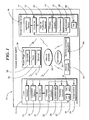
FIG. 1 is a schematic diagram of a wireless access system according to the present invention;
FIG. 2 a is a perspective view of a lock constructed in accordance with the invention;
FIG. 2 b is a perspective view of a lock constructed in accordance with another embodiment of the invention;
FIG. 3 a is a top plan view of a remote access device constructed in accordance with the invention as a key;
FIG. 3 b is a front plan view of a remote access device constructed in accordance with yet another embodiment of the invention as an application for a cell phone;
FIG. 4 is a front plan view of a Router Plug-in Unit of the wireless access system constructed in accordance with the invention;
FIG. 5 is a schematic diagram of the communication between the components of the wireless access system in a typical residential system layout in accordance with the invention;
FIG. 6 a-6 d are a flow chart of operation of the wireless access system in accordance with the invention;
FIG. 7 a is a diagram of a system showing the local communication between the remote access and the lock in accordance with the invention;
FIG. 7 b is a diagram of a system showing range and location determination in accordance with the invention;
FIG. 8 is a diagram of a system showing the method of sending access control authorization from one remote access device to another in accordance with the invention;
FIG. 9 is a circuit diagram of a remote access device constructed in accordance with still another embodiment of the invention;
FIG. 10 is a circuit diagram of a PKE lock constructed in accordance with another embodiment of the invention; and
FIG. 11 is a schematic diagram of a trip light circuit for sensing the presence of a user in accordance with the invention.
DETAILED DESCRIPTION OF THE INVENTION
The present description is made with reference to the accompanying drawings, in which various embodiments are shown. However, many different embodiments may be used, and thus the description should not be construed as limited to the embodiments set forth herein. Rather, these embodiments are provided so that this disclosure will be thorough and complete. Like numbers refer to like elements throughout, and prime notation is used to indicate similar elements or steps in alternative embodiments.
Referring to FIGS. 1, 2 a, 2 b, 3 a, 3 b, and 4, a wireless access system 10, for example, a PKE system, includes a lock 11. The lock 11 may be installed in a standard deadbolt hole and may be battery powered, for example. The lock 11 may be a human controlled (keyed) lock, for example (FIG. 2 a). The lock 11 includes an outer cylinder 12 that rotates freely around a standard key cylinder 13. When engaged, the cylinder 13 is linked to a deadbolt 14 (which may optionally be part of lock 11), thus giving the user control to extend or retract the deadbolt utilizing their key. The lock 11 includes a controller 21 or processor and wireless communication circuitry 22 for wireless communication which as will be discussed below, enable remote access device 15 to operate lock 11.
Alternatively, in another embodiment, the lock 11′ may be motor powered (FIG. 2 b). When a user is in sufficiently close vicinity or touches anywhere on the lock, or in proximity of the lock, 11′, the deadbolt 14′ is driven by the motor (not shown) to open the lock for authorized users having the remote access device 15. Of course, the lock 11 may be another type of lock or locking mechanism and may be installed in any access point, for example.
Lock 11 includes a proximity detector 27 for detecting the presence of a user. Proximity detector 27 outputs a presence signal in response to detecting a user. As discussed below, proximity detector 27 may be a capacitance touch sensor, a button, a trip light circuit, a near field detector, a radio frequency signal strength detector, an audio switch (which actuates upon receipt of audio signals of a set frequency), or the like. Proximity detector 27 outputs the presence signal to controller 21.
In one non-limiting exemplary embodiment, lock 11 is in a hibernation or low power level state. Upon triggering a proximity detector 27 outputting the presence signal by a users touch for example, controller 21 causes system 10 to wake up and start listening for remote access devices 15 advertisements. Upon finding a remote access device 15, the lock 11 communicates with (connects) to the remote access device 15, determines if the device 15 is an authorized user via an encrypted key exchange, then determines if the remote access device 15 is in range to control the lock 11, and ultimately provides access to an authorized user; all within a short or small perceived delayed time (ten seconds or less) if all the criteria is met.
Additionally, the lock 11 may be advertising or listening (sending or sampling signals) at a low frequency rate in order to conserve battery power yet establish a communication link with the remote access device 15 in advance of a users touch. In this way, increasing the speed of the authentication process to create little if any perceived delay for the user.
In another embodiment, once the lock 11 is touched by a user, the lock wireless communication circuitry 22 changes states and starts listening for a remote access device 15 advertisement. Once a connection is made authentication can be done upon connection, or upon lock or unlock request from remote access device 15. Once authenticated, the lock 11 tracks the Received Signal Strength Indicator (RSSI) of the remote access device until the algorithm determines it is within a defined accessible range from lock 11. The lock 11 gathers RSSI data and utilizes this data in an algorithm to determine the position of the remote access device 15. Once the remote access device 15 is within a pre-determined accessible distance (control range), the lock grants remote access device 15 access control to lock or unlock the lock 11. Additional antennas may be used in some embodiments for more accurate position determining, and to increase authorized user capacity and overall speed of the wireless access system 10.
Alternatively, in another embodiment, the lock may be a doorknob lock, handle lock, or other style lock for example.
Referring now additionally to FIG. 3, the wireless access system 10 includes a remote access device 15. The remote access device 15 is advantageously a key or token authorized to control the lock 11. In particular, the remote access device 15 may be a standard key including a controller 16 for controlling lock 11 via remote wireless access electronics coupled thereto (FIG. 3 a). Remote access device 15 also includes wireless communication circuitry radio 18 such as a radio in one non-limiting embodiment, for sending and receiving signals. In a preferred non-limiting example, the signal is a Bluetooth Low Energy signal.
Alternatively, or additionally, the remote access device 15 may be a mobile wireless communications device, such as, for example, a Smartphone that may include the remote wireless access electronics described above cooperating with an application 17′ stored in memory 17 (FIG. 3 b). The application 17′ may be configured to send a signal to provide access and control over the lock 11′, for example. Of course, more than one remote access device 15′ may be used and may be another type of remote access wireless device, for example, a wireless FOB without the mechanical key, as will be appreciated by those skilled in the art.
Referring now additionally to FIG. 4, the wireless access system 10 also includes a Router Plug-in Unit (RPU) 30. Connected to mains power via a power source plug-in 38 and the Internet via a Ethernet port 37 to the home router. A controller 32 controls operation of RPU 30. In one embodiment, the RPU 30 includes a radio transceiver 33 to communicate with lock 11 and/or remote access device 15, and utilizes a Bluetooth Low Energy communication protocol to communicate with the lock 11.
The RPU 30 may link to an off-site web-based server 34 via a communications network such as the internet 28, for example. This advantageously enables RPU 30 to receive near real time updates for adding or removing users, one-time access, extended access or specific timed access, and other connectivity related updates and functions at lock 11, as will be appreciated by those skilled in the art. In addition, the RPU 30 can send lock 11 status and transaction updates via the Internet 28 to the server 34 which can be viewed on a remote access device 15 or personal computer 25, for example. Additional services may be selectively provided via the Internet using the connectivity of RPU 30 with server 34, for example. While the RPU 30 is described herein as a plugin device, it will be appreciated by those skilled in the art that the functionality of the RPU 30 may be embodied in any of a number of form factors, for example, such as a mobile cellular based unit making use of cell network 35.
Referring now additionally to FIG. 5, a typical residential setup example of the wireless access system 10 is illustrated. As described above with respect to FIG. 4, the RPU 30 is typically plugged-in to the mains power via power source plug-in 38 and to the internet 28 via the home router though an Ethernet cable and port 37, at a location near the home router. RPU 30 may also communicate wirelessly to the lock 11, which may be installed on the front door, for example.
Operation of the wireless access system 10 will now be described with reference additionally to the flowchart in FIG. 6 a-6 d. The lock 11, may initially be in a low power mode in a step 101 to conserve battery power, for example. The lock 11 is typically in a low power mode; searching for authorized remote access devices 15′, for example a Smartphone, at a lower frequency to conserve battery power. In one preferred non-limiting embodiment, when a user triggers the proximity detector 27 by touch in a Step 102, or another method, the lock 11 begins to listen for remote access devices 15 in a Step 103, more specifically fobs in this embodiment. At the same time, system 10 powers up and controller 2 increases its broadcast and listening rate.
If lock 11 “sees” (receives) an advertisement from a fob 15 within a predetermined time period in a Step 104, and the fob 15 is authorized for access at that time as determined by lock 11 in a step 107, a connection is made between fob 15 and lock 11 in a step 110. It is then determined whether fob 15 is still connected by determining whether communication has occurred within a predetermined time period in a Step 112.
If the fob 15 has not timed out, then in a Step 114 a lock 11 performs a challenge response verification process to authenticate the remote access device 15. If fob 15 is verified by comparing an identification portion of the advertisement signal to information stored at system 10, lock 11 begins to gather and process location and positioning data of fob 15 in a step 117 utilizing Received Signal Strength Indication (RSSI) by way of non-limiting example. Utilizing the location and positioning algorithm in step 117, lock 11 can determine if the user is within activation range in step 118. If the user is in the activation range as determined in step 118, the control of lock 11 is given to fob 15 and the lock 11 will lock or unlock as needed in a step 119, then the lock 11 disconnects from fob 15 in a step 120 and returns to step 100 to its low power state 101.
If in Step 104 the advertisement from the fob 15 is not received within a predetermined time window or the fob is not authorized as determined in Steps 107 and a Step 109 in which the signal is ignored, or the fob connection times out in a Step 112, or the challenge response in Step 115 is not an appropriate one, then the process returns to Step 100 to be repeated.
In another embodiment, controller 21 can enable locking the door without the use of fob 15. If proximity detector 27, which may include a touch sensor, determines that lock 11 was touched at least a second time within a time window, preferably measured in seconds, in a Step 106, then controller 21 determines whether lock 11 is unlocked in a step 108. If it is determined that lock 11 is in fact unlocked in Step 108, then it is determined whether or not or not the lock 11 is touched a third time within a predetermined time window measured in seconds or less, and if in fact the lock 11 is touched three times within the time window, then controller 21 causes lock 11 to lock bolt 14 in a Step 113 and the process is returned to the beginning in Step 100 to monitor for another remote access device 15. If the deadbolt is not touched the prescribed number of times during the time window, in Steps 106 and 111, or is already in the locked state as determined in Step 108, then the process returns to Step 100 to await connection with another remote access device. In this way, a door can be locked merely by activating proximity detector 27, a predetermined number of times within a predetermined time period, or by continuously activating proximity detector 27 for a predetermined time period.
In another embodiment, the system may work without the need to touch lock 11 in step 102. In this embodiment, lock 11 and remote access device 15 determine that they are within range of each other to begin processing without the need to initially touch lock 11. This allows for the control of lock 11 well ahead of being sufficient proximity of a door to touch lock 11.
In this preferred non-limiting embodiment, an in-range remote access device 15′, such as a Smartphone, responds in a Step 121 to a broadcast advertisement from the lock 11 in a Step 121 by controller 21. If the Smartphone 15′ is authorized for access at that time as determined by controller 21 in a Step 122, a connection is made in a Step 124 between a Smartphone 15′ and lock 11. If Smartphone 15′ is authenticated during a challenge response verification process in Step 125, lock 11 begins to gather and process location and positioning data in a Step 127, utilizing RSSI or a signal from Global Positioning System (GPS) enabled Smartphone 15, for example. Utilizing the location and positioning algorithm in Step 127, the lock 11 can determine if the user is in activation range in a Step 129. In an optional Step 128, lock 11 may determine whether lock 11 has been touched prior to determining whether the user is in range in Step 129. If the user is in activation range, lock 11 will lock or unlock (reverse state) in a Step 130.
In another embodiment, information about remote access device 15′ may be stored at any one of memory 55, and memory associated with personal computer 25 or server 34. Remote access device 15 may have limited access to lock 11. By way of example, access may only be during predetermined time periods of a day, or for a limited number of times; such as a one-time use key. If the remote access device 15′, represents a one-time key as determined in Step 131, this key will be deleted from the memory or stored in the memory of system 10 as an invalid key in Step 132 to prevent further access.
As with touch process, in this proximity determination process at any time controller 21 or 32 determines that the response is inappropriate (Step 125), or remote access device 15 is not a one-time key (131) the process is returned to Step 100 to begin again. However, if the button has not been pressed in Step 128 then the process merely returns to redetermining the location of remote access device 15 in Step 127.
A hybrid approach is also possible. In a Step 105, once it is determined that the lock has been touched in Step 102 and lock 11 listens for a broadcast from fob 15 in Step 103, if a lock 11 determines in a step 105 that a Smartphone connectable advertisement response has been received within a predetermined time window; five seconds or less in a preferred embodiment, the process continues for Smartphone 15′ at Step 124 as described above. If the response is not appropriate, as determined Step 105, then the process returns to the beginning in Step 100.
In another preferred non-limiting embodiment, the location and positioning algorithm performed in a Step 127 can utilize RSSI in formation from the lock 11 to the remote access device 15′. This can be done by the remote access device 15′ receiving RSSI information from the lock 11 and transmitting this RSSI information back to the lock 11 to be processed by controller 21 for location and positioning purposes.
In another preferred non-limiting embodiment, any unauthorized user can lock the lock 11 by triggering the proximity detector three consecutive times within a predetermined time window such as discussed above in Step 106. In another possible embodiment, the lock 11 can be touched and held for greater than a predetermined time to lock the lock 11.
In another preferred non-limiting embodiment, only remote access devices 15 looking for a unique advertisement from the lock 11 will respond with a connectable advertisement. In this way, the system can provide access control to many possible authorized devices without adding additional delays per additional authorized devices.
In another embodiment in which the remote access device 15′ is a Smartphone, tablet, or similar device, the lock 11 may also request the user to verify their access control request by requiring the transmittal of a PIN, Password or other authentication code. Lock 11 transmits a signal prompting the users, on their remote access device 15′, for example, via a display on their mobile wireless communications device to answer with a PIN. Controller 21 compares the received password to authentication code previously stored by user at system 10, prior to enabling control of lock 11. This can be done to add additional security or to assist with inconclusive positioning or location information.
Referring now additionally to FIGS. 7 a and 7 b, a user 70, carries a remote access device 15′, a Smartphone in their pocket for example. Assume the remote access device 15′ is positioned within in-signal range 90. In this case, a wireless connection is made between the remote access device 15′ and the lock 11. The remote access device 15′ is authorized to control the lock 11.
In one non-limiting embodiment, when the user 70 approaches, their position is determined by receiving signals from remote access device 15′ at an exterior facing antenna 52. Once user 10 is within activation range 91, and touches the lock 11, the lock 11 radio switches to an internal antenna 50 to verify the user 70 is on the outside. If the calibrated RSSI, as determined by controller 21, or some other element of system 10, from one or more readings from the internal antenna 50 is less than the external calibrated RSSI reading or readings, user 70 is determined by controller 21 to be on the outside and the lock 11 will lock or unlock. If the calibrated RSSI from the internal antenna 50 is greater than the RSSI reading or readings from external antenna 52, user 70 is determined to be on the inside, within inside range 92 by controller 21, and the lock 11 will not operate as to prevent unauthorized entry.
The wireless access system 10 may include a calibration feature. More particularly, a connection between the remote access device 15′ and the lock 11 may be used by the algorithm to calibrate the RSSI input to adjust for varying antenna characteristics of remote access devices 15′ or changes in user behavior or environmental conditions, for example. In one non limiting example, the lock 11 determines RSSI values for remote access devices 15′ unlocking and locking events over a number of distinct communications. It then determines a maximum average activation range 91 value to calibrate with.
In another non limiting embodiment, the lock 11 can request that the remote access device 15′ send its RSSI values as received from the lock 11 and utilize these to calibrate for remote access device 15′ antenna differences. In another embodiment, the calibration is continuously self-adjusting per the last “n” number of access control events as to adjust for user behavioral changes or local condition changes over time.
The wireless access system 10 may also include a computing device 25, for example, a personal computer at the user's residence for use in a revocation process by way of example. The computing device 25 may include circuitry for wirelessly communicating with the RPU 30, remote access device 15, and/or lock 11 for revoking a permission from remote access device 15. For example, the computing device 25 may include Bluetooth Low Energy communications circuitry, for example. Other devices and communications protocols may be used in the revocation process.
While the wireless access system 10 is described herein with respect to a door, the wireless access system may be used for access control or protection of, but not limited to, appliances, a safe, heavy machinery, factory equipment, power tools, pad locks, real estate lock-boxes, garage door openers, etc., for example. Alternative remote access device 15 embodiments may include a pen, watch, jewelry, headset, FDA, laptop, etc., for example. The wireless access system 10 may be used to protect other devices or areas where it may be desired to restrict access.
The present invention lends itself to a process for transferring one-time, limited time, or permanent use Passive Keyless Entry (PKE) token key codes to a cellular or other wireless mobile remote access device 15′ for use with PKE access control devices, such as lock 11 for example. Reference is now made to FIG. 8. In one exemplary, but non limiting embodiment, a first user has a first remote access device 15′ embodied in a mobile communication device that is PKE enabled and is known to lock 11 as an authorized user. A second user has a second remote access device embodied in a mobile communication device 15″ that is PKE enabled, but is not authorized for use with lock 11. Both users can communicate locally with lock 11 via a wireless Bluetooth Low Energy network as discussed above for example. Furthermore, both users have the ability to communicate with each other via a cellular network 35 as known in the art, or other wireless communication and as a result have an almost unlimited range.
The authorized user of lock 11, chooses to send an unauthorized user an authorized token for the lock 11 by way of a mobile application 17′ on authorized remote access device 15′ to unauthorized remote access device 15″. The authorized user can select the option within mobile application 17′ on authorized remote access device 15′ for a one-time, limited time, or permanent token to send to unauthorized remote access device 15″.
In one exemplary, but non limiting embodiment, the authorization credentials are transmitted from the authorized remote access device 15′ to the currently unauthorized remote access device 15″ via the cellular network 35. Now unauthorized remote access device 15″ stores and makes use of the authorization credentials and becomes an authorized user of the lock 11. Another embodiment can be that authorized remote access device 15′ sends a request for information to unauthorized remote access device 15″ which responds to authorized remote access device with useful information such as device 15″ Bluetooth address. This information is then transmitted from authorized remote access device 15′ to the RPU 30 via the cellular network 35 to the internet, then from the internet to a home router 36 that is connected to the RPU 30. The RPU 30 then transfers identification information wirelessly to the lock 11, so that when now authorized remote access device 15″ tries to access the lock 11, it is already a known remote access device, thus speeding up the initial access control process.
It should be noted that the use of the mobile phone cellular network was used by way of non-limiting example. The key code can be sent directly to another device via SMS text message, Email, or other data communication protocols. Additionally, the key codes can be sent to another device through server 34, or a server disposed in the communications network, which can also act as a master database. Additionally, the key code master database can allow a user to manage (send, receive, revoke) locks from a secured webpage. Additionally, the key code master database can be used to restore a devices key codes via a mobile application with verification upon a lost or damaged device.
This present invention also lends itself to revoking authorization. In a process to revoke a key where the key is a smart phone, tablet or the like, once a user decides to revoke a key code, the user may send a termination request directly to the remote access device key 15′ being revoked, via the cellular network 35 using computer 25 or another computing device. If there is no response, the request is broadcast to users, for example, all users, in the “approved” network (i.e. users enrolled in the same lock 11). The request is stored in the background memory on their respective keys. Then when any authorized user is in range of the lock 11, the claimant request is activated and the key code of the requested revoked user is revoked from the lock, denying access to the revoked user. In another embodiment, the revoked key information can be sent via the cellular network 35, or through the Internet 28, to the RPU 30, then to the lock 11 to disable access.
With respect to power conservation and increased security methods for the lock 11, a remote access device 15 for example, may include the remote access application and a global positioning system (GPS) receiver 23. The GPS receiver may be used to track the location of remote access device 15 relative to the position of lock 11 and enable communication by the lock 11 only when the remote access device 15 is within range, by geo fencing for example. If the remote access device 15, i.e. mobile wireless communications device 15′ is outside the range, as determined by the GPS receiver 23, remote access 15 may tell the lock 11, via the cell network 35 and Internet 28 through the RPU 30 to go into sleep mode or turn off. Additionally, or alternatively, the location of the mobile wireless communication device 15′ may be determined via triangulation with wireless service provider base stations or towers, for example.
Alternatively, or additionally, the remote access device 15 or mobile wireless communications device 15′ may wake up, determine a position, calculate a fastest time a user could be within range of the lock 11, then wake up again at that time and recalculate. When the user is within the range, it may enable the remote access application 17, and, thus communication for authentication or other purposes.
Another method in which to conserve power consumption within remote access device 15 is to provide a wake-up mechanism internal to remote access device 15. Reference is now made to FIG. 9 in which a remote access device generally indicated as 15 constructed in accordance with another embodiment of the invention is provided. The circuitry as shown in FIG. 9 may be provided in any form factor known for a portable remote access device which as shown above is disposed within a cellphone, within a key, a fob, or any other portable entry device known in the art.
Remote access device 915 includes a radio signal generator 918 powered by a battery 900 to provide portability. Radio signal generator 918 generates a radio signal to be transmitted by an antenna 53 to be received at the lock 11 to gain access to the door in which a lock is provided as discussed above. A controller 16 controls operation of remote access device 15 and provides an input to radio signal generator 918. An authentication chip 24 provides an information input to the controller 16, such as security identification information, encryption information, and the like to be carried by the radio signal generated by radio 18 and recognized at the lock 11. In an alternative embodiment, the authentication process can be performed on the controller 16.
If radio 18 were to continuously output a radio signal even when the fob is not in use, it would exhaust battery 900 at a higher rate requiring frequent replacement, if replacement were even possible in some key fob constructions. A trigger mechanism is provided within key fob circuitry 915 to begin the creation of a radio signal by radio signal generator 918. In one preferred embodiment, an accelerometer 39 is provided within key fob circuitry 915 and outputs an acceleration signal to the controller 16 upon acceleration of the key fob 915. The acceleration signal is output to the controller 16 and the radio signal generator 918 is triggered to begin generating a radio signal. Radio signal generator 918 includes an onboard counter for measuring a predetermined time period during which transmission of the radio signal generator 918 occurs. The signal from the accelerometer 39 causes controller 16 to begin the transmission of the radio signal, and absent the acceleration signal, after the predetermined time period, the radio signal generator 918 does not operate. In this way, a radio signal is only produced when fob 15 is moving; such as when a person is in motion and approaches a lock carrying the fob for example, and not producing a radio signal when someone removes the key fob 15 from their pocket and sets it down on a table for example.
In one embodiment, light emitting diodes (LED) 901 are provided for providing a visual signal to a user of key fob circuitry 915. By way of example, LED 901 may be powered during transmission of the radio signal by radio signal generator 918, or may indicate a low battery condition.
By use of key fob circuitry 915, battery life is increased by limiting the transmission of the advertising radio signals to times when remote access device 15 is in motion. This also increases security if the user were to leave their keys near the lock 11, but just on the inside of the door. If the key were in a bowl or on a table near the door as often done, no motion would be sensed and the radio signal would not be triggered so there would be no false acceptance of an outside user resulting from the transmission of the radio signal while the key is on an interior side of the lock.
Reference is now made to FIG. 10 in which a circuit for a lock, generally indicated as 1011, having a proximity sensor triggered wake-up operation is provided. Lock circuit 1011 includes a connection to an electronic lock 1014 mounted within a door. Electronic lock 1014 is controlled by signals output by a controller 21. The lock circuit 1011 also includes a radio signal generator 1022 for communication with remote access devices 15. The circuitry 1011 is powered by batteries 1000. The radio 1022 receives radio signals from an internal antenna 50 and an external antenna 52. These antennas to the radio 1022 may be controlled by a RF switch 1001 which switches between the internal antenna 50 and external antenna 52. For the purposes of this description, internal is a direction facing within the dwelling that includes the door in which lock 11 is disposed while external is the outwardly facing direction outside of the dwelling or structure which contains the door in which the lock is disposed. The external antenna 52 may be disposed on an external side of the door.
The Radio 1022 operates under the control of a controller 21, memory 55, accelerometer 26, authentication unit 54, real time clock 1002, and proximity detector 27. During operation, controller 21 is dormant, not actively controlling bolt 14 or electronic lock 1014, so it maintains its current condition until acted upon. Proximity detector 27 may be a capacitance detector as discussed above. Proximity detector 27 outputs a presence signal 10 when the proximity of a user is detected, to radio controller 21 to wake up radio 22 to begin the lock or unlock operation.
It should be noted, that proximity detector 27 takes the form of a capacitance detector. However, as seen in FIG. 11, proximity detector 27 may include an LED 1102 and photodetector circuit 1104 between a handle 1106 and lock 1111 to form a trip light circuit. In this way, a user touches either one of handle 1102 or lock 1111, the user blocks the light path, breaking a light circuit as known in the art to signal the presence of the user.
Alternatively, the proximity detector 27 may also be a near field detector, a magnetic field detector, or even a radio signal detector for detecting the signal from a remote access device such as remote access device 15 as it is within close proximity of lock 11. In yet another embodiment, proximity detector 27 may take the form of a second lock, or handle, such as on a screen or storm door. Activation of the second lock is detected by proximity detector 27 which outputs a presence signal.
Lock circuitry 1011 also includes a memory 55 for storing data such as recognition information for authorized users or even periods of operation corresponding to specific users. By way of example, staff at a facility may only be provided access during their shift occurring at a known predetermined time. Memory 55 may also store active time periods of the day such as morning, or afternoon, when lock 11 is most in use.
A real time clock 1002 provides a real time output to controller 21 which in conjunction with access times stored in memory 55 determines when to provide access for certain authenticated users, discussed in more detail below, or when to stay on such as during known busy time periods to eliminate any operating delays. For example, between the hours of 8:00 and 9:00 when people may be showing up for work, or in a residential setting, the hours of 2:00 to 4:00 when children are returning from school, one may want the radio 22 to be broadcasting or listening at a faster rate to eliminate any delay in the operation of locking or unlocking the door.
The Authentication chip 54 creates public and private keys to be used by the controller 21 to authenticate and confirm the identity of the authorized remote access devices 15. The authentication unit 54 which includes encryption data for encrypting communications transmitted by radio 1022 or unencrypting messages received at either one of the antennas 50 or 52.
During operation, a user will approach or touch lock 11 to be detected by proximity detector 27 sending a user interaction signal to the controller 21. The radio 1022 will receive signals from a remote access device 15 at one or both of antennas 50 and 52. The received signals will be processed by the controller 21 to determine position and location as described above. Additionally, the controller verifies the remote access device 15 is authorized for access at that time as determined by utilizing the real time clock 1002 and data stored in memory 55. If access is permitted, or permitted as a function of time of day, then the actual signal received by the radio 1022 will be authenticated utilizing the authentication chip 54.
If the radio signal is recognized by the controller 21, the controller 21 will lock or unlock the electronic lock 14.
An accelerometer 26 may also provide an input to the radio 22 via the controller 21. An accelerometer 26 embedded in the door senses when the door is open or closed, or even experiences vibration such as a knock. In the absence of authorization as a function of memory unit 55 working with the real time clock 1002 and/or authentication processing utilizing authentication chip 54, the triggering of accelerometer 26 is an indication of an unwanted person at the door or even a break-in. In one embodiment, if a signal is received from accelerometer 26 in the absence of other authorizing indicia, then the controller 21 may send a signal via the radio 1022 along either one of internal antenna 50 or external antenna 52 to remote access device 15 or RPU 30 to cause an alert to be sent to a selected user.
The wireless access system 10 may be used to augment multi-factor authentication, e.g. use with a biometric identifier, personal identification number (PIN) code, key card, etc. The wireless access system 10 may also allow simultaneous multiple authentication of remote access device, for example, mobile wireless communications devices. More particularly, the wireless access system 10 may require a threshold number of authorized remote access devices 15 to be present at a same time for authentication to succeed.
The wireless access system 10 advantageously may provide increased security, for example. More particularly, the wireless access system 10 may force the user to authenticate in addition to authorization, via the remote access device 15 before the door can be opened. For example, the remote access device 15 may include an authentication device 24 for authentication via a biometric, password, PIN, shake pattern, connect-the-dots, or combination thereof, for example, prior to accessing the lock 11. In the case of the remote access application 17 on a mobile wireless communications device, for example, the application may have multiple security levels to enable these features, as will be appreciated by those skilled in the art.
With respect to security features, by using proximity sensors, switches, or the like, the wireless access system 10 may indicate whether a user locked the door, for example. When a user locks the door, for example, the remote access application 17 may log “Lock” with a time stamp so that it may be tracked and checked on the remote access device 15, i.e. the mobile wireless communications device, for example. The wireless access system 10 may include a sensing device 26 for example, an accelerometer to track door openings, for example. Based upon the accelerometer, data may be provided through the application or via the Internet or other network, for example. The sensing device 26 may be another type of device, for example, a touch sensor.
In one advantageous security feature, when the door is opened, or an attempt is made to open the door, which may be detected by the accelerometer 26 or other door opening determining methods, as will be appreciated by those skilled in the art, known, and even previously revoked, remote access devices 15 in range and/or discoverable devices, may be recorded along with a time stamp. This may capture an unauthorized user, for example.
Another advantageous feature of the wireless access system 10 may allow authorized visits, for example. More particularly, an authorized visit may be enabled by a 911 dispatcher or other authorized user to allow special or temporary access by the smart phone of a normally unauthorized user, for example. The wireless access system 10 may keep a log/audit trail. Approval may be granted by trusted a friend or special authority, for example, emergency medical services, a fire department, or a police department.
The wireless access system 10 may also include a security feature whereby when a threshold time has elapsed, the wireless access system may ignore a remote access device 15 in range. This advantageously reduces or may prevent unauthorized access that may occur from leaving a remote access device 15 that is authorized inside near the door. A timeout function (via a timer, not shown) may additionally be used in other undesired entry scenarios. The wireless access system 10 may also log all rejected pairing attempts, as will be appreciated by those skilled in the art.
The wireless access system 10 may also include a revocable key security feature. For example, the wireless access system 10 may include both revocable and non-revocable keys. If, for example, the wireless access system 10 is unable to access the server 34 to verify keys, for example, the wireless access system may force the application 17 on the remote access device 15, for example, to check the servers. If the wireless access system 10 is unable to connect or verify the keys, access is denied.
The identification of remote access device may be stored in memory 55 or at server 34, or computer 25. The status of the key as a one-time key, or limited duration key may also be stored. During the authentication process, lock 11 may compare the identification and/or password information with information stored within system 10 to determine whether access has been revoked or expired.
For example, the revocable key feature may be particularly advantageous to keep an old boyfriend, for example, who is aware that his key is being revoked from being able to turn off his remote access device 15 so that the key is not deleted. However, a wireless connection for the remote access device 15 may be a prerequisite to access in some instances.
As will be appreciated by those skilled in the art, the wireless access system 10 has the ability to transfer a key from one remote access device 15 to another with the remote access application 17, for example. It may be desired that these keys be revocable in some configurations. However, if the remote access device 15 with the key to be revoked is not accessible via the network 28, then revocation may not be guaranteed if the lock 11 is offline, for example. The wireless access system 10 advantageously addresses these challenges.
A proximity detection feature may be included in the wireless access system 10, and more particularly, the remote access device 15 may use a magnetic field sensor, such as, for example, a compass in mobile wireless communications device, as a proximity sensor to obtain a more uniform approach/departure distance calibration. A magnetic pulse or pulse sequence may be used in the lock 11 to illuminate a magnetic flux sensor in the remote access device 15 to establish proximity.
Additionally, the remote device 15, for example, a mobile wireless communications device or mobile telephone, may be qualified using both radio frequency (RF) and audio, for example. The remote access device 15 may be a source or sink of audio to help qualify proximity.
In another embodiment, as an alternative to a human driven lock, as noted above, a turn-tab (not shown) may be included that will “flip out” of the front of the lock 11 when pressed to allow the user to turn the lock on an un-powered deadbolt 14. It may be desirable that the surface area be no larger than a standard key, for example. The user pushes the turn-tab back into the lock face when done. The turn-tab may alternatively be spring loaded, for example.
In another embodiment, the turn-tab (not shown) may be added to a powered lock, for example the lock 11 described above. This is may be useful to help force ‘sticky’ locks, for example, as will be appreciated by those skilled in the art. This may also allow the user to give a manual assist to the motor in case of a strike/deadbolt 14 misalignment. This may also allow for operation in a low battery situation, for example. The turn-tab may be particularly useful in other situations.
Additionally, one of the deadbolts may have a traditional key backup as it may be needed for emergencies, for example, while the remaining deadbolts on a house may be keyless. This may eliminate the need to match physical keys on multiple deadbolts, and may reduce the cost for additional deadbolts.
The wireless access system 10 may also include an additional access feature. For example, with the RPU 30 connected to the Internet 28 through the home router 36, this provides access to the server 34 for example, it may be possible to have the lock 11 unlock via a command from the RPU 30 through the internet. In other words, the lock 11 could be opened for users who don't have a remote access device 15. More particularly, they could call a call center or service that could unlock the lock 11 via the Internet 28, for example, or via other wireless communications protocol. Also, an authorized user could provide this action as well. Additionally, fire/police could gain access by this method if the lock owner opts-in to this service. As will be appreciated by those skilled in the art, alternatively, a command could be sent from the remote access device 15.
The wireless access system 10 may also include an activation indication. For example, the remote access device 15 can signal the operator via an auditory tone, vibration or other indication when the lock is activated. This may help communicate actions to the user to reduce any confusion.
The wireless access system 10 may also include an additional security feature. For example, the wireless access system 10 may use an additional authentication channel, for example, via a WLAN, WiFi, or other communication protocol, either wired or wireless, with the remote access device 15. This may improve authentication and make spoofing considerably more difficult, as will be appreciated by those skilled in the art.
As another security feature of the wireless access system 10, if cell service and data service, for example, if the remote access device 15 is a mobile phone, are turned off, remote access application may consider this a threat related to key revocation and authentication may not be approved.
Also, the lock 11 may include a radar device, or a radar device may be coupled adjacent the lock to detect the locations of the entrant by facing outward in its sweep to resolve inside/outside ambiguity, for example. If the radar does not detect an entrant, then by default the holder of the remote access device is inside and the lock is not activated.
The lock 11 includes an interior facing directional antenna 50 and a an external facing directional antenna 52. Each is operatively coupled to the radio 22 to send signals to, and listen for signals from, remote access devices 15. If a remote access device 15 is on the interior of the lock, then the interior facing directional antenna 50 communicates with remote access device 15, and the signal strength sensed by directional antenna 50 will be greater than the signal strength sensed by directional antenna 52 (which may be no sensed signal). Lock 11, and in turn system 10, determine that remote access device is inside the home, dwelling or structure. Conversely, if remote access device 15 is exterior of the lock, exterior facing directional antenna 52 communicates with remote access device 15 and the signal strength at directional antenna 52 is greater than the signal strength received at directional antenna 50. System 10 determines that remote access device 52 is outside of the dwelling and operates as discussed above. The lock 11 compares the signals from interior facing directional antenna 50 and exterior facing directional antenna 52 to confirm the location of remote access device 15 prior to enabling the remote access device 15 to control lock 11. This prevents undesired unlocking if an authorized user is inside the door.
A mechanical or zero/low-power tilt sensor may be configured to detect break-in events, for example to the lock 11. Upon a detected break-in, the lock 11 activates and thereafter communicates to the RPU 30 to report an intruder alert. The lock 11 may also store information, in a memory, for example, if home-connect plugin is off-line.
Indeed, while the different components of the wireless access system 10 have been described with respect to a wireless protocol, it will be appreciated by those skilled in the art that the components may communicate via a wired network and protocols or a combination of wired and wireless networks. Additionally, while Bluetooth, Bluetooth Low Energy, and WLAN (i.e. WiFi) has been described herein as wireless protocols of particular merit, other wireless protocols may be used, for example, Zywave, ZigBee, near field communication (NFC), and other wireless protocols.
Many modifications and other embodiments of the invention will come to the mind of one skilled in the art having the benefit of the teachings presented in the foregoing descriptions and the associated drawings. Therefore, it is understood that the invention is not to be limited to the specific embodiments disclosed, and that modifications and embodiments are intended to be included within the invention.

Claims (31)

What is claimed is:
1. A wireless access control system for a door defining first and second areas, the wireless access control system comprising:
a lock assembly carried by the door and comprising
a lock,
a first directional antenna directed toward the first area,
a second directional antenna directed toward the second area,
lock wireless communications circuitry coupled to said first and second directional antennas, and
a lock controller coupled to said lock and said lock wireless communications circuitry;
a plugin device remote from said lock assembly in the first area; and
a remote access device remote from said lock and comprising
remote access wireless communications circuitry, and
a remote access controller configured to cooperate with said remote access wireless communications circuitry to wirelessly transmit a remote access command to said plugin device; and
said plugin device comprising
plugin device wireless communications circuitry, and
a plugin device controller coupled to said plugin device wireless communications circuitry and configured to
determine whether said remote access device is within the first area or second area based upon communication of said remote access device with said lock assembly, and
wirelessly send a lock communication enable command to said lock assembly based upon said remote access device being within the second area;
said lock controller configured to switch said lock between the locked and unlocked positions based upon wirelessly receiving, via said lock wireless communications circuitry, the remote access command from said remote access device and the lock communication enable command from said plugin device.
2. The wireless access control system of claim 1 wherein the first area comprises an interior area and the second area comprises an exterior area.
3. The wireless access control system of claim 1 wherein said plugin device controller is configured to compare signals from each of said first and second directional antennas to determine whether said remote access device is within the first or second areas.
4. The wireless access control system of claim 1 wherein said lock controller is configured to enable switching of said lock between the locked and unlocked positions based upon a received signal strength of the remote access command from said remote access device via said first and second directional antennas.
5. The wireless access control system of claim 1 wherein said lock assembly further comprises a touch sensor coupled to said lock controller, and wherein said lock controller is configured to, based upon a sensed touch from said touch sensor, switch to the first directional antenna, determine a received signal strength at each of said first and second directional antennas, and switch said lock between the locked and unlocked positions based upon the received signal strength at said second directional antenna being greater than the received signal strength at said first directional antenna.
6. The wireless access control system of claim 5 wherein said lock controller is configured to disable switching of said lock between the locked and unlocked positions based upon the received signal strength at said first directional antenna being greater than the received signal strength at said second directional antenna.
7. The wireless access control system of claim 5 wherein said lock controller is configured to determine a number of touches from said touch sensor within a given time period, and, if said lock is in the unlocked position, switch said lock to the locked position based upon exceeding a threshold number of touches within the given time period and without wirelessly receiving, via said lock wireless communications circuitry, the remote access command from said remote access device.
8. The wireless access control system of claim 5 wherein said lock controller is configured to determine a number of touches from said touch sensor within a given time period, and, if said lock is in the unlocked position, switch said lock to the locked position based upon exceeding a threshold number of touches within the given time and without exceeding a threshold received signal strength at at least one of said first and second directional antennas.
9. A wireless access control system for a door defining interior and exterior areas, the wireless access control system comprising:
a lock assembly carried by the door and comprising
a lock,
an interior directional antenna directed toward the interior area,
an exterior directional antenna directed toward the exterior area,
lock wireless communications circuitry coupled to said interior and exterior directional antennas, and
a lock controller coupled to said lock and said lock wireless communications circuitry;
a plugin device remote from said lock assembly in the interior area; and
a remote access device remote from said lock and comprising
remote access wireless communications circuitry, and
a remote access controller configured to cooperate with said remote access wireless communications circuitry to wirelessly transmit a remote access command to said plugin device; and
said plugin device comprising
plugin device wireless communications circuitry, and
a plugin device controller coupled to said plugin device wireless communications circuitry and configured to
determine whether said remote access device is within the interior area or exterior area based upon a comparison of received signals from each of the interior and exterior directional antennas,
wirelessly send a lock communication enable command to said lock assembly based upon said remote access device being within the exterior area;
said lock controller configured to
switch said lock between the locked and unlocked positions based upon wirelessly receiving, via said lock wireless communications circuitry, the remote access command from said remote access device and the lock communication enable command from said plugin device.
10. The wireless access control system of claim 9 wherein said lock controller is configured to enable switching of said lock between the locked and unlocked positions based upon a received signal strength of the remote access command from said remote access device via said interior and exterior directional antennas.
11. The wireless access control system of claim 9 wherein said lock assembly further comprises a touch sensor coupled to said lock controller, and wherein said lock controller is configured to, based upon a sensed touch from said touch sensor, switch to the interior directional antenna, determine a received signal strength at each of said interior and exterior directional antennas, and switch said lock between the locked and unlocked positions based upon the received signal strength at said exterior directional antenna being greater than the received signal strength at said interior directional antenna.
12. The wireless access control system of claim 11 wherein said lock controller is configured to disable switching of said lock between the locked and unlocked positions based upon the received signal strength at said interior directional antenna being greater than the received signal strength at said exterior directional antenna.
13. The wireless access control system of claim 11 wherein said lock controller is configured to determine a number of touches from said touch sensor within a given time period, and, if said lock is in the unlocked position, switch said lock to the locked position based upon exceeding a threshold number of touches within the given time period and without wirelessly receiving, via said lock wireless communications circuitry, the remote access command from said remote access device.
14. The wireless access control system of claim 11 wherein said lock controller is configured to determine a number of touches from said touch sensor within a given time period, and, if said lock is in the unlocked position, switch said lock to the locked position based upon exceeding a threshold number of touches within the given time and without exceeding a threshold received signal strength at at least one of said interior and exterior directional antennas.
15. A lock assembly for wireless access control system for a door defining first and second areas, the wireless access control system comprising a plugin device remote from the lock assembly in the first area and a remote access device remote from the lock, the lock assembly comprising:
a lock;
a first directional antenna directed toward the first area;
a second directional antenna directed toward the second area;
lock wireless communications circuitry coupled to said first and second directional antennas; and
a lock controller coupled to said lock and said lock wireless communications circuitry and configured to switch said lock between the locked and unlocked positions based upon wirelessly receiving, via said lock wireless communications circuitry, a remote access command wirelessly transmitted from the remote access device and a lock communication enable command wireless received from the plugin device, the lock communication enable command being wirelessly sent by the plugin device based upon a determination of the remote access device being within the second area, the determination being based upon a comparison of signals from each of said first and second directional antennas based upon communication of the remote access device with said lock assembly.
16. The lock assembly of claim 15 wherein the first area comprises an interior area and the second area comprises an exterior area.
17. The lock assembly of claim 15 wherein said lock controller is configured to enable switching of said lock between the locked and unlocked positions based upon a received signal strength of the remote access command from the remote access device via the first and second directional antennas.
18. The lock assembly of claim 15 further comprising a touch sensor coupled to said lock controller, and wherein said lock controller is configured to, based upon a sensed touch from said touch sensor, switch to the first directional antenna, determine a received signal strength at each of said first and second directional antennas, and switch said lock between the locked and unlocked positions based upon the received signal strength at said second directional antenna being greater than the received signal strength at said first directional antenna.
19. The lock assembly of claim 18 wherein said lock controller is configured to disable switching of said lock between the locked and unlocked positions based upon the received signal strength at said first directional antenna being greater than the received signal strength at said second directional antenna.
20. The lock assembly of claim 18 wherein said lock controller is configured to determine a number of touches from said touch sensor within a given time period, and, if said lock is in the unlocked position, switch said lock to the locked position based upon exceeding a threshold number of touches within the given time period and without wirelessly receiving, via said lock wireless communications circuitry, the remote access command from the remote access device.
21. The lock assembly of claim 18 wherein said lock controller is configured to determine a number of touches from said touch sensor within a given time period, and, if said lock is in the unlocked position, switch said lock to the locked position based upon exceeding a threshold number of touches within the given time and without exceeding a threshold received signal strength at at least one of said first and second directional antennas.
22. A plugin device for a wireless access control system for a door defining first and second areas, the wireless access control system comprising a lock assembly carried by the door and comprising a lock, a first directional antenna directed toward the first area, a second directional antenna directed toward the second area, lock wireless communications circuitry coupled to the first and second directional antennas, and a lock controller coupled to the lock and the lock wireless communications circuitry, the plugin device being remote from the lock assembly in the first area and comprising:
plugin device wireless communications circuitry; and
a plugin device controller coupled to said plugin device wireless communications circuitry and configured to
compare signals from each of said first and second directional antennas based upon communication of the remote access device with said lock assembly to determine whether a remote access device is within the first area or second area, and
wirelessly send a lock communication enable command to the lock assembly based upon the remote access device being within the second area, the lock controller switching the lock between the locked and unlocked positions based upon wirelessly receiving, via the lock wireless communications circuitry, a remote access command from the remote access device and the lock communication enable command.
23. The plugin device of claim 22 wherein the first area comprises an interior area and the second area comprises an exterior area.
24. A method of wireless access control for a door defining first and second areas, the wireless access control system comprising a lock assembly carried by the door and comprising a lock, a first directional antenna directed toward the first area, a second directional antenna directed toward the second area, lock wireless communications circuitry coupled to the first and second directional antennas, and a lock controller coupled to the lock and the lock wireless communications circuitry, the method comprising
using a remote access device remote from the lock to wirelessly transmit a remote access command to a plugin device remote from the lock assembly in the first area;
using the plugin device to
compare signals from each of the first and second directional antennas based upon communication of the remote access device with the lock assembly to determine whether the remote access device is within the first area or second area, and
wirelessly send a lock communication enable command to the lock assembly based upon the remote access device being within the second area; and
using the lock controller to switch the lock between the locked and unlocked positions based upon wirelessly receiving the remote access command from the remote access device and the lock communication enable command from the plugin device.
25. The method of claim 24 wherein the first area comprises an interior area and the second area comprises an exterior area.
26. The method of claim 24 wherein the plugin device is further used to communicate with the lock assembly to disable the lock based upon the remote access device being within the first area.
27. The method of claim 24 wherein the lock controller is used to enable switching of the lock between the locked and unlocked positions based upon a received signal strength of the remote access command from the remote access device via the first and second directional antennas.
28. The method of claim 24 wherein the lock assembly further comprises a touch sensor coupled to the lock controller, and wherein the lock controller is used to, based upon a sensed touch from the touch sensor, switch to the first directional antenna, determine a received signal strength at each of the first and second directional antennas, and switch the lock between the locked and unlocked positions based upon the received signal strength at the second directional antenna being greater than the received signal strength at the first directional antenna.
29. The method of claim 28 wherein the lock controller is used to disable switching of the lock between the locked and unlocked positions based upon the received signal strength at the first directional antenna being greater than the received signal strength at second the directional antenna.
30. The method of claim 28 wherein the lock controller is used to determine a number of touches from the touch sensor within a given time period, and, if the lock is in the unlocked position, switch the lock to the locked position based upon exceeding a threshold number of touches within the given time period and without wirelessly receiving, via the lock wireless communications circuitry, the remote access command from the remote access device.
31. The method of claim 28 wherein the lock controller is used to determine a number of touches from the touch sensor within a given time period, and, if the lock is in the unlocked position, switch the lock to the locked position based upon exceeding a threshold number of touches within the given time and without exceeding a threshold received signal strength at at least one of the first and second directional antennas.
US14/681,243 2011-03-17 2015-04-08 Wireless access control system and related methods Active US9218696B2 (en)

Priority Applications (1)

Application Number Priority Date Filing Date Title
US14/681,243 US9218696B2 (en) 2011-03-17 2015-04-08 Wireless access control system and related methods

Applications Claiming Priority (5)

Application Number Priority Date Filing Date Title
US201161453737P 2011-03-17 2011-03-17
US13/415,365 US9336637B2 (en) 2011-03-17 2012-03-08 Wireless access control system and related methods
US13/654,132 US9196104B2 (en) 2011-03-17 2012-10-17 Wireless access control system and related methods
US13/734,671 US9057210B2 (en) 2011-03-17 2013-01-04 Wireless access control system and related methods
US14/681,243 US9218696B2 (en) 2011-03-17 2015-04-08 Wireless access control system and related methods

Related Parent Applications (2)

Application Number Title Priority Date Filing Date
US13/654,132 Continuation US9196104B2 (en) 2011-03-17 2012-10-17 Wireless access control system and related methods
US13/734,671 Division US9057210B2 (en) 2011-03-17 2013-01-04 Wireless access control system and related methods

Publications (2)

Publication Number Publication Date
US20150213663A1 US20150213663A1 (en) 2015-07-30
US9218696B2 true US9218696B2 (en) 2015-12-22

Family

ID=48743508

Family Applications (4)

Application Number Title Priority Date Filing Date
US13/734,671 Expired - Fee Related US9057210B2 (en) 2011-03-17 2013-01-04 Wireless access control system and related methods
US14/681,281 Abandoned US20150213658A1 (en) 2011-03-17 2015-04-08 Wireless access control system and related methods
US14/681,243 Active US9218696B2 (en) 2011-03-17 2015-04-08 Wireless access control system and related methods
US14/681,263 Active US9378598B2 (en) 2011-03-17 2015-04-08 Wireless access control system and related methods

Family Applications Before (2)

Application Number Title Priority Date Filing Date
US13/734,671 Expired - Fee Related US9057210B2 (en) 2011-03-17 2013-01-04 Wireless access control system and related methods
US14/681,281 Abandoned US20150213658A1 (en) 2011-03-17 2015-04-08 Wireless access control system and related methods

Family Applications After (1)

Application Number Title Priority Date Filing Date
US14/681,263 Active US9378598B2 (en) 2011-03-17 2015-04-08 Wireless access control system and related methods

Country Status (1)

Country Link
US (4) US9057210B2 (en)

Cited By (41)

* Cited by examiner, † Cited by third party
Publication number Priority date Publication date Assignee Title
US9501883B2 (en) 2011-03-17 2016-11-22 Unikey Technologies Inc. Wireless access control system including lock assembly generated magnetic field based unlocking and related methods
US9501880B2 (en) 2011-03-17 2016-11-22 Unikey Technologies Inc. Wireless access control system including remote access wireless device generated magnetic field based unlocking and related methods
US20170096123A1 (en) * 2014-05-22 2017-04-06 Huf Huelsbeck & Fuerst Gmbh & Co. Kg System and method for controlling access
US10043332B2 (en) 2016-05-27 2018-08-07 SkyBell Technologies, Inc. Doorbell package detection systems and methods
US20190088056A1 (en) * 2015-06-01 2019-03-21 Schlage Lock Company Llc Antenna diversity implementation for wireless locks
US20190114888A1 (en) * 2017-10-17 2019-04-18 Wistron Neweb Corporation Time-reversal indoor detection system and method
US20190139343A1 (en) * 2017-11-06 2019-05-09 Wfe Technology Corp. Electronic lock system, electronic lock device, and method for unlocking electronic lock device
US20190304226A1 (en) * 2018-03-28 2019-10-03 Denso International America, Inc. Reflective Environment Detection Systems And Methods
US10440165B2 (en) 2013-07-26 2019-10-08 SkyBell Technologies, Inc. Doorbell communication and electrical systems
US10672238B2 (en) 2015-06-23 2020-06-02 SkyBell Technologies, Inc. Doorbell communities
US10674119B2 (en) 2015-09-22 2020-06-02 SkyBell Technologies, Inc. Doorbell communication systems and methods
US10706702B2 (en) 2015-07-30 2020-07-07 Skybell Technologies Ip, Llc Doorbell package detection systems and methods
US10719999B2 (en) 2017-04-27 2020-07-21 Schlage Lock Company Llc Technologies for determining intent in an access control system
US10876324B2 (en) 2017-01-19 2020-12-29 Endura Products, Llc Multipoint lock
US10909825B2 (en) 2017-09-18 2021-02-02 Skybell Technologies Ip, Llc Outdoor security systems and methods
US11004312B2 (en) 2015-06-23 2021-05-11 Skybell Technologies Ip, Llc Doorbell communities
US11066850B2 (en) 2017-07-25 2021-07-20 Amesbury Group, Inc Access handle for sliding doors
US11074790B2 (en) 2019-08-24 2021-07-27 Skybell Technologies Ip, Llc Doorbell communication systems and methods
US11102027B2 (en) 2013-07-26 2021-08-24 Skybell Technologies Ip, Llc Doorbell communication systems and methods
US11111698B2 (en) 2016-12-05 2021-09-07 Endura Products, Llc Multipoint lock
US11140253B2 (en) 2013-07-26 2021-10-05 Skybell Technologies Ip, Llc Doorbell communication and electrical systems
US11184589B2 (en) 2014-06-23 2021-11-23 Skybell Technologies Ip, Llc Doorbell communication systems and methods
US11228739B2 (en) 2015-03-07 2022-01-18 Skybell Technologies Ip, Llc Garage door communication systems and methods
US11339589B2 (en) 2018-04-13 2022-05-24 Dormakaba Usa Inc. Electro-mechanical lock core
US11343473B2 (en) 2014-06-23 2022-05-24 Skybell Technologies Ip, Llc Doorbell communication systems and methods
US11381686B2 (en) 2015-04-13 2022-07-05 Skybell Technologies Ip, Llc Power outlet cameras
US11386730B2 (en) 2013-07-26 2022-07-12 Skybell Technologies Ip, Llc Smart lock systems and methods
US11401733B2 (en) * 2016-04-15 2022-08-02 Spectrum Brands, Inc. Wireless lockset with integrated angle of arrival (AOA) detection
US11466473B2 (en) 2018-04-13 2022-10-11 Dormakaba Usa Inc Electro-mechanical lock core
US20220410840A1 (en) * 2021-06-23 2022-12-29 Hyundai Motor Company System and Method for Controlling Vehicle
US11575537B2 (en) 2015-03-27 2023-02-07 Skybell Technologies Ip, Llc Doorbell communication systems and methods
US11631043B2 (en) 2015-11-02 2023-04-18 Sargent Manufacturing Company Methods and systems for ensuring secure delivery of parcels using internet-enabled storage receptacle
US11639617B1 (en) 2019-04-03 2023-05-02 The Chamberlain Group Llc Access control system and method
US11651668B2 (en) 2017-10-20 2023-05-16 Skybell Technologies Ip, Llc Doorbell communities
US11651665B2 (en) 2013-07-26 2023-05-16 Skybell Technologies Ip, Llc Doorbell communities
US11663864B2 (en) 2019-11-27 2023-05-30 Schlage Lock Company Llc Ultra-wideband technologies for seamless access control
US11746565B2 (en) 2019-05-01 2023-09-05 Endura Products, Llc Multipoint lock assembly for a swinging door panel
US11889009B2 (en) 2013-07-26 2024-01-30 Skybell Technologies Ip, Llc Doorbell communication and electrical systems
US11913254B2 (en) 2017-09-08 2024-02-27 dormakaba USA, Inc. Electro-mechanical lock core
US11933076B2 (en) 2016-10-19 2024-03-19 Dormakaba Usa Inc. Electro-mechanical lock core
US11961344B2 (en) 2021-07-09 2024-04-16 Schlage Lock Company Llc Ultra-wideband accessory devices for radio frequency intent detection in access control systems

Families Citing this family (208)

* Cited by examiner, † Cited by third party
Publication number Priority date Publication date Assignee Title
US9027681B2 (en) 2009-12-04 2015-05-12 Massachusetts Institute Of Technology Hybrid sensor-enabled electric wheel and associated systems, multi-hub wheel spoking systems, and methods of manufacturing and installing wheel spokes
US20140002236A1 (en) * 2010-12-02 2014-01-02 Viscount Security Systems Inc. Door Lock, System and Method for Remotely Controlled Access
US20140292481A1 (en) * 2011-03-17 2014-10-02 Unikey Technologies, Inc. Wireless access control system and related methods
US9057210B2 (en) 2011-03-17 2015-06-16 Unikey Technologies, Inc. Wireless access control system and related methods
US9196104B2 (en) 2011-03-17 2015-11-24 Unikey Technologies Inc. Wireless access control system and related methods
US9336637B2 (en) 2011-03-17 2016-05-10 Unikey Technologies Inc. Wireless access control system and related methods
EP2815535B1 (en) * 2012-02-13 2018-11-14 Schlage Lock Company LLC Credential management system
CA2873271C (en) 2012-05-08 2018-01-02 Schlage Lock Company Llc Remote management of electronic products
DE102012221997A1 (en) * 2012-05-25 2013-11-28 Robert Bosch Gmbh power tool
EP3637376B1 (en) * 2012-08-16 2021-10-27 Schlage Lock Company LLC Wireless reader system
US9508206B2 (en) 2012-08-16 2016-11-29 Schlage Lock Company Llc Usage of GPS on door security
US9497069B2 (en) * 2012-10-11 2016-11-15 Pismo Labs Technology Limited Managing actions of a network device through a manual information input module
US9549323B2 (en) 2012-12-03 2017-01-17 Samsung Electronics Co., Ltd. Method and mobile terminal for controlling screen lock
US10240365B2 (en) 2012-12-12 2019-03-26 Spectrum Brands, Inc. Electronic lock system having proximity mobile device
KR102134713B1 (en) 2012-12-21 2020-07-16 니다 테크 스웨덴 에이비 Method, tool control node, computer-readable recording medium and power tool device, for enabling unlocking and locking of power tool
US10366552B2 (en) * 2012-12-21 2019-07-30 Nida Tech Sweden Ab Method for locking, unlocking and positioning of a tool
US8919024B2 (en) * 2013-02-06 2014-12-30 Karl F. Milde, Jr. Secure smartphone-operated gun trigger lock
US9312926B2 (en) * 2013-02-07 2016-04-12 Schlage Lock Company Llc System and method for NFC peer-to-peer authentication and secure data transfer
WO2014124405A2 (en) 2013-02-08 2014-08-14 Schlage Lock Company Llc Control system and method
US9922481B2 (en) 2014-03-12 2018-03-20 August Home, Inc. Intelligent door lock system with third party secured access to a dwelling
US11072945B2 (en) 2013-03-15 2021-07-27 August Home, Inc. Video recording triggered by a smart lock device
US11441332B2 (en) 2013-03-15 2022-09-13 August Home, Inc. Mesh of cameras communicating with each other to follow a delivery agent within a dwelling
US11527121B2 (en) 2013-03-15 2022-12-13 August Home, Inc. Door lock system with contact sensor
US10691953B2 (en) 2013-03-15 2020-06-23 August Home, Inc. Door lock system with one or more virtual fences
US11043055B2 (en) 2013-03-15 2021-06-22 August Home, Inc. Door lock system with contact sensor
US11421445B2 (en) 2013-03-15 2022-08-23 August Home, Inc. Smart lock device with near field communication
US11802422B2 (en) 2013-03-15 2023-10-31 August Home, Inc. Video recording triggered by a smart lock device
US9818247B2 (en) 2015-06-05 2017-11-14 August Home, Inc. Intelligent door lock system with keypad
US10181232B2 (en) * 2013-03-15 2019-01-15 August Home, Inc. Wireless access control system and methods for intelligent door lock system
US9647996B2 (en) * 2013-03-15 2017-05-09 August Home, Inc. Low power device with encryption
US10388094B2 (en) 2013-03-15 2019-08-20 August Home Inc. Intelligent door lock system with notification to user regarding battery status
US9447609B2 (en) 2013-03-15 2016-09-20 August Home, Inc. Mobile device that detects tappings/vibrations which are used to lock or unlock a door
US10443266B2 (en) 2013-03-15 2019-10-15 August Home, Inc. Intelligent door lock system with manual operation and push notification
US11352812B2 (en) 2013-03-15 2022-06-07 August Home, Inc. Door lock system coupled to an image capture device
US9574372B2 (en) 2013-03-15 2017-02-21 August Home, Inc. Intelligent door lock system that minimizes inertia applied to components
US10140828B2 (en) 2015-06-04 2018-11-27 August Home, Inc. Intelligent door lock system with camera and motion detector
US9382739B1 (en) 2013-03-15 2016-07-05 August Home, Inc. Determining right or left hand side door installation
US9916746B2 (en) 2013-03-15 2018-03-13 August Home, Inc. Security system coupled to a door lock system
US9704314B2 (en) * 2014-08-13 2017-07-11 August Home, Inc. BLE/WiFi bridge that detects signal strength of Bluetooth LE devices at an exterior of a dwelling
US9644398B1 (en) 2013-03-15 2017-05-09 August Home, Inc. Intelligent door lock system with a haptic device
US20160319571A1 (en) * 2014-03-12 2016-11-03 August Home Inc. Intelligent door lock system with optical sensor
US9633548B2 (en) * 2013-04-23 2017-04-25 Canary Connect, Inc. Leveraging a user's geo-location to arm and disarm a network enabled device
US11391065B2 (en) * 2013-06-10 2022-07-19 Smart Armor Protected, LLC Wireless method and apparatus for remote lock operating with mobile communication device
US20150004903A1 (en) * 2013-06-28 2015-01-01 Nate LYMAN Chipless Near Field-Communication for Mobile Devices
FR3007876B1 (en) * 2013-06-28 2016-09-16 Continental Automotive France METHOD FOR PROCESSING PRESENCE SIGNAL IN A FREE HAND ACCESS SYSTEM OF A CAPACITIVE SENSOR VEHICLE
US9300484B1 (en) 2013-07-12 2016-03-29 Smartlabs, Inc. Acknowledgement as a propagation of messages in a simulcast mesh network
EP2833330B1 (en) 2013-07-30 2018-07-18 Paxton Access Limited Communication method and system
US9763086B2 (en) 2013-08-27 2017-09-12 Qualcomm Incorporated Owner access point to control the unlocking of an entry
CA2928487A1 (en) * 2013-10-25 2015-04-30 Nanopay Inc. Systems, methods and devices for generating secure electronic authentication and payment processing
US9251700B2 (en) 2013-10-28 2016-02-02 Smartlabs, Inc. Methods and systems for powerline and radio frequency communications
US9347242B2 (en) 2013-10-28 2016-05-24 Smartlabs, Inc. Systems and methods to automatically detect a door state
US9324203B2 (en) 2013-10-28 2016-04-26 Smartlabs, Inc. Systems and methods to control a door keypad
US9317984B2 (en) 2013-10-28 2016-04-19 Smartlabs, Inc. Systems and methods to control locking and unlocking of doors using powerline and radio frequency communications
AU2014342341B2 (en) 2013-10-29 2019-07-25 Cubic Corporation Fare collection using wireless beacons
US9363264B2 (en) * 2013-11-25 2016-06-07 At&T Intellectual Property I, L.P. Networked device access control
DE102014105241A1 (en) * 2013-12-05 2015-06-11 Deutsche Post Ag Locking unit, housing with locking unit and method for unlocking one or more doors of the housing
US9361786B2 (en) 2013-12-05 2016-06-07 Smartlabs, Inc. Systems and methods to control window coverings using powerline and radio frequency communications
US9529345B2 (en) 2013-12-05 2016-12-27 Smartlabs, Inc. Systems and methods to automatically adjust window coverings
TWI532017B (en) 2013-12-25 2016-05-01 正文科技股份有限公司 Wireless control method, wireless host and switch control device
US20150228134A1 (en) * 2014-02-12 2015-08-13 Viking Access Systems, Llc Movable barrier operator configured for remote actuation
US10192377B2 (en) * 2014-02-12 2019-01-29 Elika Access Systems, Llc Movable barrier operator configured for remote actuation
WO2015124168A1 (en) * 2014-02-18 2015-08-27 Bekey A/S Controlling access to a location
US9691198B2 (en) * 2014-03-12 2017-06-27 August Home, Inc. Wireless access control system and methods for intelligent door lock system
US20150269799A1 (en) * 2014-03-19 2015-09-24 Meghan Martinez Wireless door locking system
US9353551B2 (en) * 2014-03-19 2016-05-31 Meghan Martinez Wireless door locking system
JP6340716B2 (en) * 2014-03-24 2018-06-13 パナソニックIpマネジメント株式会社 Short-range wireless communication system for vehicles, portable device and in-vehicle device
DE102014104051A1 (en) * 2014-03-24 2015-09-24 Martin Lehmann Gmbh & Co. Kg Radio-controlled electromechanical locking system and method for operating a radio-controlled electromechanical locking system
WO2015154046A1 (en) 2014-04-04 2015-10-08 Superpedestrian, Inc. Systems, methods, and devices for the operation of electrically motorized vehicles
US10308065B2 (en) 2014-04-04 2019-06-04 Superpedestrian, Inc. Devices and methods for connecting a spoke to a hub
US10115256B2 (en) * 2014-04-07 2018-10-30 Videx, Inc. Remote administration of an electronic key to facilitate use by authorized persons
US20150294518A1 (en) * 2014-04-10 2015-10-15 Ford Global Technologies, Llc Remotely programmed keyless vehicle entry system
US10274909B2 (en) 2014-04-25 2019-04-30 Vivint, Inc. Managing barrier and occupancy based home automation system
US10657749B2 (en) 2014-04-25 2020-05-19 Vivint, Inc. Automatic system access using facial recognition
US10235822B2 (en) * 2014-04-25 2019-03-19 Vivint, Inc. Automatic system access using facial recognition
US10127754B2 (en) * 2014-04-25 2018-11-13 Vivint, Inc. Identification-based barrier techniques
WO2015187731A1 (en) * 2014-06-02 2015-12-10 Schlage Lock Company Llc System and method for signifying intent for lock operation
EP2958085A1 (en) * 2014-06-17 2015-12-23 Burg-Wächter Kg Method for operating an electronic access system
US9894066B2 (en) 2014-07-30 2018-02-13 Master Lock Company Llc Wireless firmware updates
US9455839B2 (en) * 2014-07-30 2016-09-27 Master Lock Company Llc Wireless key management for authentication
US9996999B2 (en) 2014-07-30 2018-06-12 Master Lock Company Llc Location tracking for locking device
US9600949B2 (en) 2014-07-30 2017-03-21 Master Lock Company Llc Wireless key management for authentication
US9747739B2 (en) 2014-08-18 2017-08-29 Noke, Inc. Wireless locking device
US10158550B2 (en) 2014-08-19 2018-12-18 Sensormatic Electronics, LLC Access control system with omni and directional antennas
US9865144B2 (en) 2014-08-19 2018-01-09 Sensormatic Electronics, LLC Video recognition in frictionless access control system
US9697656B2 (en) * 2014-08-19 2017-07-04 Sensormatic Electronics, LLC Method and system for access control proximity location
US10235854B2 (en) 2014-08-19 2019-03-19 Sensormatic Electronics, LLC Tailgating detection in frictionless access control system
EP3120334B1 (en) * 2014-08-21 2022-04-27 Cordiner, Peter Alexander An electronic locking system
WO2016030857A1 (en) * 2014-08-28 2016-03-03 Telezygology Inc System for accessing a secure delivery
KR102192419B1 (en) 2014-09-11 2020-12-17 삼성전자주식회사 Method of controlling electronic device using wearable device and method of operating electronic device
US9704317B2 (en) 2014-09-23 2017-07-11 Schlage Lock Company Llc Long range wireless credentials for entryway
US9378596B2 (en) * 2014-09-30 2016-06-28 I-Tek Metal Mfg. Co., Ltd Door access control system
US20160116510A1 (en) 2014-10-27 2016-04-28 Master Lock Company Predictive battery warnings for an electronic locking device
EP3224056A4 (en) 2014-11-24 2018-08-22 Superpedestrian, Inc. Devices and methods of a motorized wheel
WO2016089832A1 (en) 2014-12-02 2016-06-09 Carrier Corporation Access control system with virtual card data
EP3228098B1 (en) * 2014-12-02 2022-08-17 Carrier Corporation Capturing user intent when interacting with multiple access controls
US9728022B2 (en) 2015-01-28 2017-08-08 Noke, Inc. Electronic padlocks and related methods
US9871906B2 (en) 2015-02-09 2018-01-16 Samsung Electronics Co., Ltd. Method and apparatus for communicating advertisement signal including shared information between devices in wireless communication system
PT108254A (en) * 2015-02-24 2016-08-24 Simões Alexandre RADIO-FREQUENCY KEY ACTIVATION SYSTEM
US9374667B1 (en) * 2015-03-24 2016-06-21 Awarepoint Corporation Bluetooth low energy rapid room entry system and method
EP3072754A1 (en) 2015-03-27 2016-09-28 Assa Abloy AB Method, device, computer program and computer program product for determining whether a portable key device is located in an active area in relation to a barrier
EP3073284A1 (en) 2015-03-27 2016-09-28 Assa Abloy AB Method, device, computer program and computer program product for determining whether a portable key device is located in an active area in relation to a barrier
WO2016163923A1 (en) 2015-04-07 2016-10-13 Nidatech Sweden Ab Enhanced time of arrival positioning system
US9875647B1 (en) * 2015-04-27 2018-01-23 Google Inc. Systems and methods for presenting security questions via connected security system
US9713002B2 (en) 2015-05-15 2017-07-18 Honeywell International Inc. Access control via a mobile device
US9589403B2 (en) 2015-05-15 2017-03-07 Honeywell International Inc. Access control via a mobile device
EP3298592A1 (en) * 2015-05-20 2018-03-28 Sensormatic Electronics LLC Portable device having directional ble antenna
DE102015108026C5 (en) * 2015-05-21 2020-03-05 Carl Fuhr Gmbh & Co. Kg Locking system and method for operating a locking system for a building door
TWM517236U (en) * 2015-05-26 2016-02-11 Lintex Co Ltd Electronic lock components and lock thereof
US9947158B2 (en) 2015-06-01 2018-04-17 Schlage Lock Company Llc Access control device commissioning
IN2015CH04016A (en) * 2015-08-03 2015-08-14 Varadharajan Marur Srikrishna
US9633495B2 (en) * 2015-08-03 2017-04-25 Caterpillar Inc. System and method for wirelessly authenticating a device having a sensor
US9732483B2 (en) 2015-09-11 2017-08-15 Westfield Retail Solutions, Inc. Vehicle barrier system
US20170098335A1 (en) * 2015-10-02 2017-04-06 Stanley Security Solutions, Inc. Cardless access control with electronic locks using smartphones
US9524601B1 (en) 2015-12-28 2016-12-20 Unikey Technologies Inc. Wireless access control system including door position based lock switching and related methods
US9721413B2 (en) 2015-10-13 2017-08-01 Unikey Technologies Inc. Wireless access control system operating in automatic calibration mode and including door position based lock switching and related methods
CN105321244B (en) * 2015-12-07 2017-09-19 讯美电子科技有限公司 Gate control system computer remote authorization method and system
CN106898061A (en) * 2015-12-18 2017-06-27 英业达科技有限公司 Intelligent door lock system and its method
US9697658B1 (en) 2015-12-28 2017-07-04 Unikey Technologies Inc. Wireless access control system including closed door position and interior area remote access wireless communications device based lock switching and related methods
EP3188136A1 (en) * 2015-12-28 2017-07-05 Marques, SA Electronic door lock and operation method thereof
US9697661B1 (en) 2015-12-28 2017-07-04 Unikey Technologies Inc. Wireless access control system including closed door position and exterior area remote access wireless communications device based lock switching and related methods
CN105654585A (en) * 2015-12-30 2016-06-08 潍坊鼎丰智能科技有限公司 Intelligent lock and control method thereof
US10028221B2 (en) * 2016-01-04 2018-07-17 Motorola Mobility Llc Reducing energy usage with a low power sensor core
US9843591B2 (en) * 2016-02-08 2017-12-12 Rockwell Automation Technologies, Inc. Beacon-based industrial automation access authorization
US11170616B2 (en) 2016-03-16 2021-11-09 Triax Technologies, Inc. System and interfaces for managing workplace events
US10528902B2 (en) 2016-03-16 2020-01-07 Triax Technologies, Inc. System and interfaces for managing workplace events
US10769562B2 (en) * 2016-03-16 2020-09-08 Triax Technologies, Inc. Sensor based system and method for authorizing operation of worksite equipment using a locally stored access control list
EP3220508B1 (en) * 2016-03-16 2020-09-23 TTI (Macao Commercial Offshore) Limited Power tool battery pack with wireless communication
US11810032B2 (en) 2016-03-16 2023-11-07 Triax Technologies, Inc. Systems and methods for low-energy wireless applications using networked wearable sensors
DE102016003774A1 (en) * 2016-04-03 2017-10-05 HiAsset GmbH Doorbell station with local communication connection
WO2017180388A1 (en) * 2016-04-11 2017-10-19 Carrier Corporation Capturing behavioral user intent when interacting with multiple access controls
CN109074618B (en) 2016-04-11 2024-04-09 开利公司 Capturing user intent while interacting with multiple access controls
CN109074691B (en) 2016-04-11 2022-07-29 开利公司 Capturing individual user intent while interacting with multiple access control devices
CN109074690A (en) 2016-04-11 2018-12-21 开利公司 Communication user is captured when interacting with multiple access control apparatus to be intended to
WO2017181175A1 (en) 2016-04-15 2017-10-19 Schlage Lock Company Llc Wireless credential proximity control
CN107305706A (en) * 2016-04-20 2017-10-31 北大方正集团有限公司 Control locking method and central lock system
US10440574B2 (en) 2016-06-12 2019-10-08 Apple Inc. Unlocking a device
US10540834B2 (en) * 2016-10-11 2020-01-21 Sensormatic Electronics, LLC Frictionless access control system with user tracking and Omni and dual probe directional antennas
US10438463B2 (en) 2016-10-14 2019-10-08 ASSA ABLOY Residential Group, Inc. Access control system and method
US10008061B2 (en) 2016-10-24 2018-06-26 Sera4 Ltd. Secure access to physical resources using asymmetric cryptography
EP3542349A1 (en) * 2016-11-17 2019-09-25 Assa Abloy AB Controlling a lock based on an activation signal and position of portable key device
US10815717B2 (en) 2016-11-28 2020-10-27 Honda Motor Co., Ltd. System and method for providing hands free operation of at least one vehicle door
US10380817B2 (en) 2016-11-28 2019-08-13 Honda Motor Co., Ltd. System and method for providing hands free operation of at least one vehicle door
DE202017107149U1 (en) 2016-12-01 2018-03-05 Kurtz Gmbh Crack gap forming tool for producing a particle foam part and apparatus for producing a particle foam part
CN110168180B (en) * 2016-12-28 2021-09-17 福特汽车公司 Method and apparatus for adjusting the annunciation rate of a device to reduce battery usage
US10769877B2 (en) * 2017-03-02 2020-09-08 OpenPath Security Inc. Secure handsfree proximity-based access control
WO2018160343A1 (en) * 2017-03-02 2018-09-07 Carrier Corporation Access control system with dynamic performance tuning
WO2018160375A1 (en) * 2017-03-02 2018-09-07 Carrier Corporation Access control system with dynamic performance tuning
GB201704629D0 (en) 2017-03-23 2017-05-10 Glue Ab Automated delivery security system
US11465878B2 (en) 2017-03-31 2022-10-11 Otis Elevator Company Visual status indicator for door and lock state
WO2018195081A1 (en) 2017-04-18 2018-10-25 Amesbury Group, Inc. Modular electronic deadbolt systems
US10053056B1 (en) * 2017-04-20 2018-08-21 Denso International America, Inc. Multi-step vehicle entry authorization
CN108986258A (en) * 2017-06-05 2018-12-11 杭州英杰电子有限公司 A kind of universal access controller and its workflow
US20190007548A1 (en) * 2017-06-28 2019-01-03 The Travelers Indemnity Company Systems and methods for discrete location-based functionality
US20190026483A1 (en) * 2017-07-18 2019-01-24 Design SHIFT Proximity Protected Keyless Security System
US10157537B1 (en) 2017-08-16 2018-12-18 Coastal Steel Manufacturing, Llc Remotely controlled access security system
JP6817581B2 (en) * 2017-08-31 2021-01-20 パナソニックIpマネジメント株式会社 Electric lock control system, electric lock system, control method of electric lock control system, and program
US20190111890A1 (en) * 2017-10-12 2019-04-18 Hitachi, Ltd. Terminal-vehicle linking method, terminal-vehicle linking apparatus, and terminal-vehicle linking program
CN109801403A (en) * 2017-11-16 2019-05-24 杭州海康威视数字技术股份有限公司 A kind of information cuing method, device, system and intelligent electronic lock
US11151240B2 (en) * 2017-12-11 2021-10-19 Carrier Corporation Access key card that cancels automatically for safety and security
US20190188934A1 (en) * 2017-12-19 2019-06-20 Centurylink Intellectual Property Llc Low-Power Wireless for Access Control
IT201800000672A1 (en) * 2018-01-10 2019-07-10 Sandro Salari System equipment and method to govern the access and control of an environment in a secure, multiple and selective way.
WO2019169119A1 (en) * 2018-02-28 2019-09-06 Passivebolt, Inc. Electronic door lock
US10968660B2 (en) 2018-02-28 2021-04-06 Passivebolt, Inc. Electronic door lock
CN110294372B (en) * 2018-03-23 2023-02-28 奥的斯电梯公司 Wireless signal device, elevator service request system and method
CN110400396B (en) 2018-04-25 2023-08-22 开利公司 System and method for seamless entry and intent recognition using mobile phone
US10783731B2 (en) 2018-04-27 2020-09-22 Spectrum Brands, Inc. Wireless tag-based lock actuation systems and methods
US11004287B2 (en) 2018-05-07 2021-05-11 Carrier Corporation Seamless hands-free reader route to a destination
CN108691458B (en) * 2018-05-09 2020-01-24 珠海格力电器股份有限公司 Door lock, door lock control method and device
WO2019241827A1 (en) * 2018-06-19 2019-12-26 Sine Group Pty Ltd Remote access system and method
US10453281B1 (en) 2018-07-02 2019-10-22 Schlage Lock Company Llc Tri-angled antenna array for secure access control
KR102323002B1 (en) * 2018-08-08 2021-11-09 주식회사 슈프리마에이치큐 Access control system and access control method using the same
EP3627457A1 (en) * 2018-09-24 2020-03-25 Hoppe Ag Access system
SG11202103770SA (en) * 2018-10-15 2021-05-28 Paylessgate Corp Position determination system, position determination apparatus, position determination method, position determination program, and computer-readable storage medium and storage device
US10825273B2 (en) 2018-10-16 2020-11-03 Edst, Llc Smart thermostat hub
CN110021085B (en) * 2018-10-29 2021-09-28 深圳市微开互联科技有限公司 Door opening system and method for code scanning parallel verification
US11834866B2 (en) 2018-11-06 2023-12-05 Amesbury Group, Inc. Flexible coupling for electronic deadbolt systems
US11250654B2 (en) 2018-11-06 2022-02-15 Carrier Corporation Access control system with sensor
US11661771B2 (en) * 2018-11-13 2023-05-30 Amesbury Group, Inc. Electronic drive for door locks
CN109322547A (en) * 2018-11-30 2019-02-12 温州市龙湾海伦五金厂 More keyhole cast a glamor over formulas disorderly open the lock of alarm
US10964141B2 (en) * 2018-12-18 2021-03-30 Ncr Corporation Internet-of-things (IoT) enabled lock with management platform processing
US11352817B2 (en) 2019-01-25 2022-06-07 Noke, Inc. Electronic lock and interchangeable shackles
US11189117B2 (en) * 2019-01-30 2021-11-30 Zhuhai Unitech Power Technology Co., Ltd. Method and system for controlling a smart lock
US11288908B2 (en) * 2019-04-26 2022-03-29 Carrier Corporation Geolocation based security in intrusion systems
US10697203B1 (en) * 2019-05-30 2020-06-30 Digilock Asia Ltd. Electromechanical lock with adjustable backset
US10711489B1 (en) 2019-05-30 2020-07-14 Digilock Asia Ltd. Electromechanical multi-directional lock
US10914098B2 (en) 2019-05-30 2021-02-09 Digilock Asia Ltd. Enclosure latch system
CN110290348A (en) * 2019-06-13 2019-09-27 浙江大华技术股份有限公司 A kind of smart electronics opal and its awakening method, device
US11227044B2 (en) * 2019-08-22 2022-01-18 Microsoft Technology Licensing, Llc Systems and methods for generating and managing user authentication rules of a computing device
US10970950B2 (en) * 2019-08-30 2021-04-06 Ademco Inc. Systems and methods for activating a security action responsive to proximal detection and identification of a wireless device
US11010995B2 (en) 2019-09-06 2021-05-18 Videx, Inc. Access control system with dynamic access permission processing
ES2815749B2 (en) * 2019-09-30 2023-02-23 Verisure Sarl SECURITY MONITORING SYSTEM
US11546774B2 (en) * 2019-10-07 2023-01-03 James Zheng Du Methods, systems, apparatuses, and devices for controlling access to an access control location
CN110901586B (en) * 2019-11-29 2021-12-17 东风商用车有限公司 Commercial vehicle theft tracking and positioning system
CN111190379B (en) * 2019-12-30 2021-10-08 中祖建设安装工程有限公司 Method and system for controlling working state of positioning device in building
US11002061B1 (en) 2020-01-04 2021-05-11 Passivebolt, Inc. Electronic door system
EP3882872A1 (en) * 2020-03-17 2021-09-22 Sony Group Corporation An electronic device, an access control device, and related methods
US11170593B1 (en) * 2020-05-05 2021-11-09 Royal Caribbean Cruises Ltd. Multifunction smart door device
CN111882707B (en) * 2020-07-15 2022-08-19 珠海优特电力科技股份有限公司 Lock control method and device
JP2022026122A (en) * 2020-07-30 2022-02-10 富士フイルムビジネスイノベーション株式会社 Booth, information processing system, and program
KR20220015845A (en) 2020-07-31 2022-02-08 주식회사 모카시스템 Reader and control method thereof
ES2852701A1 (en) * 2021-02-01 2021-09-14 Elparking Internet S L U TELEMATIC ACCESS CONTROL DEVICE (Machine-translation by Google Translate, not legally binding)
US11842588B2 (en) 2021-02-08 2023-12-12 Panduit Corp. System for controlling access to an enclosure
USD996945S1 (en) * 2021-05-20 2023-08-29 Pin Genie Limited Smart lock
US20230068820A1 (en) * 2021-09-02 2023-03-02 Radio Systems Corporation Pet Door
US20230186707A1 (en) * 2021-12-09 2023-06-15 Thomas James West Asset enclosure lock system with encrypted identification and credential functionality
WO2023196524A1 (en) * 2022-04-06 2023-10-12 Security Enhancement Systems, Llc High-security access and alarm system with electronic deadbolt locking device
US11587380B1 (en) * 2022-07-12 2023-02-21 Marc Tobias System for transmitting an authorization code in a security application
US20240119771A1 (en) * 2022-10-07 2024-04-11 Leslie Mark Kolpan Carter Security System for Normally-Open Facility Access by Known Populations

Citations (39)

* Cited by examiner, † Cited by third party
Publication number Priority date Publication date Assignee Title
JP2000145222A (en) 1998-11-12 2000-05-26 Mazda Motor Corp Keyless entry system
US6072402A (en) * 1992-01-09 2000-06-06 Slc Technologies, Inc. Secure entry system with radio communications
US6236333B1 (en) 1998-06-17 2001-05-22 Lear Automotive Dearborn, Inc. Passive remote keyless entry system
US20020013909A1 (en) 2000-04-29 2002-01-31 Markus Baumeister Method of dynamic determination of access rights
JP2003262072A (en) 2002-03-11 2003-09-19 Nabco Ltd Door apparatus for vehicle
KR20030083538A (en) 2002-05-03 2003-10-30 오일권 Central management key
US20030222758A1 (en) 2002-01-24 2003-12-04 Robin Willats Vehicle access control and start system
KR20040093937A (en) 2003-04-30 2004-11-09 주식회사 케이. 디. 티 A digital door lock system and control method
KR20050005786A (en) 2003-06-30 2005-01-14 소니 가부시끼 가이샤 Device registration system, device registration server, device registration method, device registration program, storage medium, and terminal device
US20060164208A1 (en) * 2005-01-14 2006-07-27 Secureall Corporation Universal hands free key and lock system and method
US7173516B2 (en) 2004-02-06 2007-02-06 Wayne-Dalton Corp. Operating system for a motorized barrier operator
US20080018437A1 (en) 2006-05-11 2008-01-24 Trimark Corporation Illuminated vehicle grab handle with keypad for keyless entry
US20080117176A1 (en) 2006-11-20 2008-05-22 Hon Hai Precision Industry Co., Ltd. Electronic devices having a touch screen and method for starting the electronic devices
US20080231433A1 (en) 2007-03-21 2008-09-25 Denso International America, Inc. Ambient noise controlled buzzer answerback
KR20080086623A (en) 2007-03-23 2008-09-26 한국델파이주식회사 Method for control remote keyless entry of passive keyless entry system
US20080238610A1 (en) 2006-09-29 2008-10-02 Einar Rosenberg Apparatus and method using near field communications
US20090002153A1 (en) 2006-05-11 2009-01-01 Viktors Berstis Key Fob and System for Indicating the Lock Status of a Door Lock
US20090066476A1 (en) * 2007-04-17 2009-03-12 Fonekey, Inc. Method of self-service access control for frequent guests of a housing facility
CN101532353A (en) 2008-03-11 2009-09-16 株式会社易保 Door lock system with touch pad unit and control method thereof
KR20100001206U (en) 2008-07-25 2010-02-03 주식회사 아이레보 Doorlock using touch pad apparatus
US20100052931A1 (en) 2008-08-26 2010-03-04 Gm Global Technology Operations, Inc. Gesture control key fob
US20100059231A1 (en) 2008-09-10 2010-03-11 Benson Thomas Methods and apparatus for supporting tubulars
US7701331B2 (en) 2006-06-12 2010-04-20 Tran Bao Q Mesh network door lock
US20100164683A1 (en) 2006-09-12 2010-07-01 Tyco Safety Products Canada Ltd. Method and apparatus for automatically disarming a security system
US20100201536A1 (en) * 2009-02-10 2010-08-12 William Benjamin Robertson System and method for accessing a structure using a mobile device
US20100245038A1 (en) 2009-03-25 2010-09-30 Lear Corporation Automatic walk-away detection
US20100306549A1 (en) 2008-01-30 2010-12-02 Evva Sicherheitstechnologie Gmbh Method and device for managing access control
US20110016971A1 (en) * 2009-07-21 2011-01-27 Openings, Lp Door monitoring system
US20110223868A1 (en) 2010-03-12 2011-09-15 Denso Corporation Portable equipment detecting system
WO2011159921A1 (en) 2010-06-16 2011-12-22 Delphian Systems, LLC Wireless device enabled locking system
WO2012064263A1 (en) 2010-11-09 2012-05-18 Zaplox Ab Method and system for remote operation of an installation
US20120234058A1 (en) 2011-03-17 2012-09-20 Unlkey Technologies, Inc. Wireless access control system and related methods
US20120258681A1 (en) 2011-04-07 2012-10-11 Mobile Security Worldwide Ltd. Method for emergency signaling via mobile telecommunications device
US20120280783A1 (en) * 2011-05-02 2012-11-08 Apigy Inc. Systems and methods for controlling a locking mechanism using a portable electronic device
US20130176107A1 (en) 2011-03-17 2013-07-11 Unikey Technologies, Inc Wireless access control system and related methods
US20130237193A1 (en) 2011-03-17 2013-09-12 Unikey Technologies, Inc. Wireless access control system and related methods
US20130241694A1 (en) 2012-03-16 2013-09-19 Secureall Corporation Non-contact electronic door locks having specialized radio frequency beam formation
US20140077929A1 (en) 2012-03-08 2014-03-20 Unikey Technologies, Inc. Wireless access control system and related methods
US20140292481A1 (en) 2011-03-17 2014-10-02 Unikey Technologies, Inc. Wireless access control system and related methods

Family Cites Families (4)

* Cited by examiner, † Cited by third party
Publication number Priority date Publication date Assignee Title
US20030189481A1 (en) * 2002-04-04 2003-10-09 Laurence Hamid Remote actuation system, device and method
EP2282297A1 (en) * 2009-07-21 2011-02-09 Openways Sas Security system to control the opening of locking devices using encoded acoustic verifications
EP2500872A1 (en) * 2011-03-08 2012-09-19 Openways Sas Secured method for controlling the opening of locking devices by means of a communication object such as a mobile phone
US9082241B2 (en) * 2012-01-06 2015-07-14 Nxp B.V. Wireless communications circuit

Patent Citations (39)

* Cited by examiner, † Cited by third party
Publication number Priority date Publication date Assignee Title
US6072402A (en) * 1992-01-09 2000-06-06 Slc Technologies, Inc. Secure entry system with radio communications
US6236333B1 (en) 1998-06-17 2001-05-22 Lear Automotive Dearborn, Inc. Passive remote keyless entry system
JP2000145222A (en) 1998-11-12 2000-05-26 Mazda Motor Corp Keyless entry system
US20020013909A1 (en) 2000-04-29 2002-01-31 Markus Baumeister Method of dynamic determination of access rights
US20030222758A1 (en) 2002-01-24 2003-12-04 Robin Willats Vehicle access control and start system
JP2003262072A (en) 2002-03-11 2003-09-19 Nabco Ltd Door apparatus for vehicle
KR20030083538A (en) 2002-05-03 2003-10-30 오일권 Central management key
KR20040093937A (en) 2003-04-30 2004-11-09 주식회사 케이. 디. 티 A digital door lock system and control method
KR20050005786A (en) 2003-06-30 2005-01-14 소니 가부시끼 가이샤 Device registration system, device registration server, device registration method, device registration program, storage medium, and terminal device
US7173516B2 (en) 2004-02-06 2007-02-06 Wayne-Dalton Corp. Operating system for a motorized barrier operator
US20060164208A1 (en) * 2005-01-14 2006-07-27 Secureall Corporation Universal hands free key and lock system and method
US20080018437A1 (en) 2006-05-11 2008-01-24 Trimark Corporation Illuminated vehicle grab handle with keypad for keyless entry
US20090002153A1 (en) 2006-05-11 2009-01-01 Viktors Berstis Key Fob and System for Indicating the Lock Status of a Door Lock
US7701331B2 (en) 2006-06-12 2010-04-20 Tran Bao Q Mesh network door lock
US20100164683A1 (en) 2006-09-12 2010-07-01 Tyco Safety Products Canada Ltd. Method and apparatus for automatically disarming a security system
US20080238610A1 (en) 2006-09-29 2008-10-02 Einar Rosenberg Apparatus and method using near field communications
US20080117176A1 (en) 2006-11-20 2008-05-22 Hon Hai Precision Industry Co., Ltd. Electronic devices having a touch screen and method for starting the electronic devices
US20080231433A1 (en) 2007-03-21 2008-09-25 Denso International America, Inc. Ambient noise controlled buzzer answerback
KR20080086623A (en) 2007-03-23 2008-09-26 한국델파이주식회사 Method for control remote keyless entry of passive keyless entry system
US20090066476A1 (en) * 2007-04-17 2009-03-12 Fonekey, Inc. Method of self-service access control for frequent guests of a housing facility
US20100306549A1 (en) 2008-01-30 2010-12-02 Evva Sicherheitstechnologie Gmbh Method and device for managing access control
CN101532353A (en) 2008-03-11 2009-09-16 株式会社易保 Door lock system with touch pad unit and control method thereof
KR20100001206U (en) 2008-07-25 2010-02-03 주식회사 아이레보 Doorlock using touch pad apparatus
US20100052931A1 (en) 2008-08-26 2010-03-04 Gm Global Technology Operations, Inc. Gesture control key fob
US20100059231A1 (en) 2008-09-10 2010-03-11 Benson Thomas Methods and apparatus for supporting tubulars
US20100201536A1 (en) * 2009-02-10 2010-08-12 William Benjamin Robertson System and method for accessing a structure using a mobile device
US20100245038A1 (en) 2009-03-25 2010-09-30 Lear Corporation Automatic walk-away detection
US20110016971A1 (en) * 2009-07-21 2011-01-27 Openings, Lp Door monitoring system
US20110223868A1 (en) 2010-03-12 2011-09-15 Denso Corporation Portable equipment detecting system
WO2011159921A1 (en) 2010-06-16 2011-12-22 Delphian Systems, LLC Wireless device enabled locking system
WO2012064263A1 (en) 2010-11-09 2012-05-18 Zaplox Ab Method and system for remote operation of an installation
US20120234058A1 (en) 2011-03-17 2012-09-20 Unlkey Technologies, Inc. Wireless access control system and related methods
US20130176107A1 (en) 2011-03-17 2013-07-11 Unikey Technologies, Inc Wireless access control system and related methods
US20130237193A1 (en) 2011-03-17 2013-09-12 Unikey Technologies, Inc. Wireless access control system and related methods
US20140292481A1 (en) 2011-03-17 2014-10-02 Unikey Technologies, Inc. Wireless access control system and related methods
US20120258681A1 (en) 2011-04-07 2012-10-11 Mobile Security Worldwide Ltd. Method for emergency signaling via mobile telecommunications device
US20120280783A1 (en) * 2011-05-02 2012-11-08 Apigy Inc. Systems and methods for controlling a locking mechanism using a portable electronic device
US20140077929A1 (en) 2012-03-08 2014-03-20 Unikey Technologies, Inc. Wireless access control system and related methods
US20130241694A1 (en) 2012-03-16 2013-09-19 Secureall Corporation Non-contact electronic door locks having specialized radio frequency beam formation

Non-Patent Citations (2)

* Cited by examiner, † Cited by third party
Title
Dumas et al., U.S. Appl. No. 14/681,263, filed Apr. 8, 2015.
Dumas et al., U.S. Appl. No. 14/681,281, filed Apr. 8, 2015.

Cited By (59)

* Cited by examiner, † Cited by third party
Publication number Priority date Publication date Assignee Title
US9501883B2 (en) 2011-03-17 2016-11-22 Unikey Technologies Inc. Wireless access control system including lock assembly generated magnetic field based unlocking and related methods
US9501880B2 (en) 2011-03-17 2016-11-22 Unikey Technologies Inc. Wireless access control system including remote access wireless device generated magnetic field based unlocking and related methods
US10440165B2 (en) 2013-07-26 2019-10-08 SkyBell Technologies, Inc. Doorbell communication and electrical systems
US11102027B2 (en) 2013-07-26 2021-08-24 Skybell Technologies Ip, Llc Doorbell communication systems and methods
US11889009B2 (en) 2013-07-26 2024-01-30 Skybell Technologies Ip, Llc Doorbell communication and electrical systems
US11132877B2 (en) 2013-07-26 2021-09-28 Skybell Technologies Ip, Llc Doorbell communities
US11651665B2 (en) 2013-07-26 2023-05-16 Skybell Technologies Ip, Llc Doorbell communities
US11140253B2 (en) 2013-07-26 2021-10-05 Skybell Technologies Ip, Llc Doorbell communication and electrical systems
US11386730B2 (en) 2013-07-26 2022-07-12 Skybell Technologies Ip, Llc Smart lock systems and methods
US11362853B2 (en) 2013-07-26 2022-06-14 Skybell Technologies Ip, Llc Doorbell communication systems and methods
US10440166B2 (en) 2013-07-26 2019-10-08 SkyBell Technologies, Inc. Doorbell communication and electrical systems
US10434988B2 (en) * 2014-05-20 2019-10-08 Huf Huelsbeck & Fuerst Gmbh & Co. Kg System and method for controlling access
US10589718B2 (en) * 2014-05-22 2020-03-17 Huf Huelsbeck & Fuerst Gmbh & Co. Kg System and method for controlling access
US20170096123A1 (en) * 2014-05-22 2017-04-06 Huf Huelsbeck & Fuerst Gmbh & Co. Kg System and method for controlling access
US20180050663A1 (en) * 2014-05-22 2018-02-22 Huf Huelsbeck & Fuerst Gmbh & Co. Kg System and method for controlling access
US11184589B2 (en) 2014-06-23 2021-11-23 Skybell Technologies Ip, Llc Doorbell communication systems and methods
US11343473B2 (en) 2014-06-23 2022-05-24 Skybell Technologies Ip, Llc Doorbell communication systems and methods
US11388373B2 (en) 2015-03-07 2022-07-12 Skybell Technologies Ip, Llc Garage door communication systems and methods
US11228739B2 (en) 2015-03-07 2022-01-18 Skybell Technologies Ip, Llc Garage door communication systems and methods
US11575537B2 (en) 2015-03-27 2023-02-07 Skybell Technologies Ip, Llc Doorbell communication systems and methods
US11381686B2 (en) 2015-04-13 2022-07-05 Skybell Technologies Ip, Llc Power outlet cameras
US10748360B2 (en) * 2015-06-01 2020-08-18 Schlage Lock Company Llc Antenna diversity implementation for wireless locks
US20190088056A1 (en) * 2015-06-01 2019-03-21 Schlage Lock Company Llc Antenna diversity implementation for wireless locks
US10672238B2 (en) 2015-06-23 2020-06-02 SkyBell Technologies, Inc. Doorbell communities
US11004312B2 (en) 2015-06-23 2021-05-11 Skybell Technologies Ip, Llc Doorbell communities
US10706702B2 (en) 2015-07-30 2020-07-07 Skybell Technologies Ip, Llc Doorbell package detection systems and methods
US10674119B2 (en) 2015-09-22 2020-06-02 SkyBell Technologies, Inc. Doorbell communication systems and methods
US11631043B2 (en) 2015-11-02 2023-04-18 Sargent Manufacturing Company Methods and systems for ensuring secure delivery of parcels using internet-enabled storage receptacle
US11361641B2 (en) 2016-01-27 2022-06-14 Skybell Technologies Ip, Llc Doorbell package detection systems and methods
US11401733B2 (en) * 2016-04-15 2022-08-02 Spectrum Brands, Inc. Wireless lockset with integrated angle of arrival (AOA) detection
US11952799B2 (en) 2016-04-15 2024-04-09 Assa Abloy Americas Residential Inc. Wireless lockset with integrated angle of arrival (AoA) detection
US10043332B2 (en) 2016-05-27 2018-08-07 SkyBell Technologies, Inc. Doorbell package detection systems and methods
US11933076B2 (en) 2016-10-19 2024-03-19 Dormakaba Usa Inc. Electro-mechanical lock core
US11111698B2 (en) 2016-12-05 2021-09-07 Endura Products, Llc Multipoint lock
US10876324B2 (en) 2017-01-19 2020-12-29 Endura Products, Llc Multipoint lock
US11151818B2 (en) 2017-04-27 2021-10-19 Schlage Lock Company Llc Technologies for determining intent in an access control system
US10719999B2 (en) 2017-04-27 2020-07-21 Schlage Lock Company Llc Technologies for determining intent in an access control system
US11066850B2 (en) 2017-07-25 2021-07-20 Amesbury Group, Inc Access handle for sliding doors
US11913254B2 (en) 2017-09-08 2024-02-27 dormakaba USA, Inc. Electro-mechanical lock core
US10909825B2 (en) 2017-09-18 2021-02-02 Skybell Technologies Ip, Llc Outdoor security systems and methods
US11810436B2 (en) 2017-09-18 2023-11-07 Skybell Technologies Ip, Llc Outdoor security systems and methods
US10510235B2 (en) * 2017-10-17 2019-12-17 Wistron Neweb Corporation Time-reversal indoor detection system and method
US20190114888A1 (en) * 2017-10-17 2019-04-18 Wistron Neweb Corporation Time-reversal indoor detection system and method
US11651668B2 (en) 2017-10-20 2023-05-16 Skybell Technologies Ip, Llc Doorbell communities
US20190139343A1 (en) * 2017-11-06 2019-05-09 Wfe Technology Corp. Electronic lock system, electronic lock device, and method for unlocking electronic lock device
US20190304226A1 (en) * 2018-03-28 2019-10-03 Denso International America, Inc. Reflective Environment Detection Systems And Methods
US10839627B2 (en) * 2018-03-28 2020-11-17 Denso International America, Inc. Reflective environment detection systems and methods
US11447980B2 (en) 2018-04-13 2022-09-20 Dormakaba Usa Inc. Puller tool
US11466473B2 (en) 2018-04-13 2022-10-11 Dormakaba Usa Inc Electro-mechanical lock core
US11339589B2 (en) 2018-04-13 2022-05-24 Dormakaba Usa Inc. Electro-mechanical lock core
US11639617B1 (en) 2019-04-03 2023-05-02 The Chamberlain Group Llc Access control system and method
US11746565B2 (en) 2019-05-01 2023-09-05 Endura Products, Llc Multipoint lock assembly for a swinging door panel
US11854376B2 (en) 2019-08-24 2023-12-26 Skybell Technologies Ip, Llc Doorbell communication systems and methods
US11074790B2 (en) 2019-08-24 2021-07-27 Skybell Technologies Ip, Llc Doorbell communication systems and methods
US11663864B2 (en) 2019-11-27 2023-05-30 Schlage Lock Company Llc Ultra-wideband technologies for seamless access control
US20220410840A1 (en) * 2021-06-23 2022-12-29 Hyundai Motor Company System and Method for Controlling Vehicle
US11919477B2 (en) * 2021-06-23 2024-03-05 Hyundai Motor Company System and method for controlling vehicle
US11961344B2 (en) 2021-07-09 2024-04-16 Schlage Lock Company Llc Ultra-wideband accessory devices for radio frequency intent detection in access control systems
US11961347B2 (en) 2023-01-24 2024-04-16 Schlage Lock Company Llc Seamless access control

Also Published As

Publication number Publication date
US20150211259A1 (en) 2015-07-30
US20150213663A1 (en) 2015-07-30
US9378598B2 (en) 2016-06-28
US20130176107A1 (en) 2013-07-11
US9057210B2 (en) 2015-06-16
US20150213658A1 (en) 2015-07-30

Similar Documents

Publication Publication Date Title
US9218696B2 (en) Wireless access control system and related methods
US9978195B2 (en) Wireless access control system including remote access wireless device generated magnetic field based unlocking and related methods
US9972151B2 (en) Wireless access control system including lock assembly generated magnetic field based unlocking and related methods
US9336637B2 (en) Wireless access control system and related methods
US20140077929A1 (en) Wireless access control system and related methods
EP2941844A1 (en) Wireless access control system and related methods
US20140292481A1 (en) Wireless access control system and related methods
WO2015023737A1 (en) Wireless access control system and related methods
US9196104B2 (en) Wireless access control system and related methods
US10708410B2 (en) Systems and methods for controlling a locking mechanism using a portable electronic device
AU2020249425B2 (en) Physical access control systems with localization-based intent detection
US20160086400A1 (en) Wireless access control system including distance based lock assembly and remote access device enrollment and related methods
JP4665649B2 (en) Lock control device and program
JP4595921B2 (en) Authentication system, communication method and program

Legal Events

Date Code Title Description
AS Assignment

Owner name: UNIKEY TECHNOLOGIES, INC., FLORIDA

Free format text: ASSIGNMENT OF ASSIGNORS INTEREST;ASSIGNORS:DUMAS, PHILIP C.;BENNETT, THOMAS;REEL/FRAME:035358/0800

Effective date: 20130220

STCF Information on status: patent grant

Free format text: PATENTED CASE

FEPP Fee payment procedure

Free format text: MAINTENANCE FEE REMINDER MAILED (ORIGINAL EVENT CODE: REM.); ENTITY STATUS OF PATENT OWNER: SMALL ENTITY

AS Assignment

Owner name: WESTERN ALLIANCE BANK, NEVADA

Free format text: INTELLECTUAL PROPERTY SECURITY AGREEMENT;ASSIGNOR:UNIKEY TECHNOLOGIES INC.;REEL/FRAME:050872/0727

Effective date: 20190731

FEPP Fee payment procedure

Free format text: SURCHARGE FOR LATE PAYMENT, SMALL ENTITY (ORIGINAL EVENT CODE: M2554); ENTITY STATUS OF PATENT OWNER: SMALL ENTITY

MAFP Maintenance fee payment

Free format text: PAYMENT OF MAINTENANCE FEE, 4TH YR, SMALL ENTITY (ORIGINAL EVENT CODE: M2551); ENTITY STATUS OF PATENT OWNER: SMALL ENTITY

Year of fee payment: 4

FEPP Fee payment procedure

Free format text: MAINTENANCE FEE REMINDER MAILED (ORIGINAL EVENT CODE: REM.); ENTITY STATUS OF PATENT OWNER: SMALL ENTITY

FEPP Fee payment procedure

Free format text: 7.5 YR SURCHARGE - LATE PMT W/IN 6 MO, SMALL ENTITY (ORIGINAL EVENT CODE: M2555); ENTITY STATUS OF PATENT OWNER: SMALL ENTITY

MAFP Maintenance fee payment

Free format text: PAYMENT OF MAINTENANCE FEE, 8TH YR, SMALL ENTITY (ORIGINAL EVENT CODE: M2552); ENTITY STATUS OF PATENT OWNER: SMALL ENTITY

Year of fee payment: 8