US9210686B2 - Radio communication device, base station, method for radio communication, program and radio communication system - Google Patents
Radio communication device, base station, method for radio communication, program and radio communication system Download PDFInfo
- Publication number
- US9210686B2 US9210686B2 US13/978,749 US201213978749A US9210686B2 US 9210686 B2 US9210686 B2 US 9210686B2 US 201213978749 A US201213978749 A US 201213978749A US 9210686 B2 US9210686 B2 US 9210686B2
- Authority
- US
- United States
- Prior art keywords
- paging
- cycle
- radio communication
- base station
- communication device
- Prior art date
- Legal status (The legal status is an assumption and is not a legal conclusion. Google has not performed a legal analysis and makes no representation as to the accuracy of the status listed.)
- Active, expires
Links
- 230000006854 communication Effects 0.000 title claims abstract description 150
- 238000004891 communication Methods 0.000 title claims abstract description 150
- 238000000034 method Methods 0.000 title claims description 32
- 230000008859 change Effects 0.000 claims abstract description 46
- 230000004044 response Effects 0.000 claims abstract description 26
- 238000001514 detection method Methods 0.000 claims abstract description 10
- 230000006870 function Effects 0.000 claims description 22
- 230000009467 reduction Effects 0.000 claims description 4
- 238000003672 processing method Methods 0.000 claims 1
- 238000010586 diagram Methods 0.000 description 55
- 125000002015 acyclic group Chemical group 0.000 description 36
- 238000012544 monitoring process Methods 0.000 description 19
- 230000008569 process Effects 0.000 description 11
- 230000005540 biological transmission Effects 0.000 description 9
- 230000007704 transition Effects 0.000 description 9
- 238000006243 chemical reaction Methods 0.000 description 8
- 230000000873 masking effect Effects 0.000 description 5
- 230000011664 signaling Effects 0.000 description 5
- 238000001914 filtration Methods 0.000 description 4
- 239000000470 constituent Substances 0.000 description 3
- 239000000284 extract Substances 0.000 description 3
- 230000003321 amplification Effects 0.000 description 2
- 238000004364 calculation method Methods 0.000 description 2
- 238000004590 computer program Methods 0.000 description 2
- 230000008878 coupling Effects 0.000 description 2
- 238000010168 coupling process Methods 0.000 description 2
- 238000005859 coupling reaction Methods 0.000 description 2
- 230000003247 decreasing effect Effects 0.000 description 2
- 235000011389 fruit/vegetable juice Nutrition 0.000 description 2
- 230000006872 improvement Effects 0.000 description 2
- 238000003199 nucleic acid amplification method Methods 0.000 description 2
- 238000012546 transfer Methods 0.000 description 2
- 230000006978 adaptation Effects 0.000 description 1
- 230000002776 aggregation Effects 0.000 description 1
- 238000004220 aggregation Methods 0.000 description 1
- 230000004075 alteration Effects 0.000 description 1
- 230000008901 benefit Effects 0.000 description 1
- 230000007175 bidirectional communication Effects 0.000 description 1
- 238000012790 confirmation Methods 0.000 description 1
- 125000004122 cyclic group Chemical group 0.000 description 1
- 238000013480 data collection Methods 0.000 description 1
- 230000007547 defect Effects 0.000 description 1
- 230000003111 delayed effect Effects 0.000 description 1
- 230000000694 effects Effects 0.000 description 1
- 238000005516 engineering process Methods 0.000 description 1
- 230000007774 longterm Effects 0.000 description 1
- 238000012986 modification Methods 0.000 description 1
- 230000004048 modification Effects 0.000 description 1
Images


Classifications
-
- H—ELECTRICITY
- H04—ELECTRIC COMMUNICATION TECHNIQUE
- H04W—WIRELESS COMMUNICATION NETWORKS
- H04W68/00—User notification, e.g. alerting and paging, for incoming communication, change of service or the like
- H04W68/02—Arrangements for increasing efficiency of notification or paging channel
-
- H—ELECTRICITY
- H04—ELECTRIC COMMUNICATION TECHNIQUE
- H04W—WIRELESS COMMUNICATION NETWORKS
- H04W4/00—Services specially adapted for wireless communication networks; Facilities therefor
- H04W4/70—Services for machine-to-machine communication [M2M] or machine type communication [MTC]
-
- H—ELECTRICITY
- H04—ELECTRIC COMMUNICATION TECHNIQUE
- H04W—WIRELESS COMMUNICATION NETWORKS
- H04W52/00—Power management, e.g. TPC [Transmission Power Control], power saving or power classes
- H04W52/02—Power saving arrangements
-
- H—ELECTRICITY
- H04—ELECTRIC COMMUNICATION TECHNIQUE
- H04W—WIRELESS COMMUNICATION NETWORKS
- H04W68/00—User notification, e.g. alerting and paging, for incoming communication, change of service or the like
- H04W68/005—Transmission of information for alerting of incoming communication
-
- H—ELECTRICITY
- H04—ELECTRIC COMMUNICATION TECHNIQUE
- H04W—WIRELESS COMMUNICATION NETWORKS
- H04W88/00—Devices specially adapted for wireless communication networks, e.g. terminals, base stations or access point devices
- H04W88/08—Access point devices
-
- H04W4/005—
Definitions
- the invention relates to a radio communication device, a base station, a method for radio communication, a program and a radio communication system.
- eNodeB Micro-cell base station
- NeNB Home eNodeB, femtocell base station, compact base station for cell phones
- RRH Remote Radio Head
- an RRC_Connected mode and an RRC_Idle mode are defined.
- the RRC_Connected mode is a state in which a connection is established between the UE and the eNodeB, and the UE is capable of sending an uplink signal and receiving a downlink signal.
- the RRC_Idle mode is a state in which power of the UE is saved, and the UE in the RRC_Idle mode monitors the paging channel from the eNodeB, and transitions to the RRC_Connected mode when being called in the paging channel.
- the UE of the RRC_Idle mode monitors the paging channel at the paging cycle.
- power consumption of the UE can be reduced when the paging cycle is long, there is a tendency that a delay from when the UE is called to when it responds becomes large.
- an intermittent receiving cycle that is similar to this is disclosed for example in Patent Literature 1.
- MTC Machine Type Communications
- a case may be assumed in which an MTC terminal collects electrocardiogram information of a human, and transmits the electrocardiogram information to a server by using uplink when a certain trigger condition is met.
- a case may be assumed in which a vending machine is caused to function as an MTC terminal, and a server causes the vending machine under management to report sales once every certain cycle (for example, every 30 days).
- Such an MTC terminal by way of example has the following features in general, however, not every MTC terminal needs to have all of the following features, and which of the features is to be endowed depends on applications.
- the paging cycle of a radio communication device that is not connected to a base station was in an equal interval. Due to this, there has been a problem that a degree of freedom of the paging cycle to be applied to a radio communication device is low.
- the invention has been made in view of the above problem, and what is aimed by the invention is to provide novel and improved radio communication device, base station, method for radio communication, program and radio communication system that can flexibly switch the cycle for a communication of the paging channel.
- a base station including a radio communication section that communicates by radio with a radio communication device, and a paging control section that causes the radio communication section to send a paging channel for the radio communication device in accordance with a first cycle.
- the paging channel includes information indicating a second cycle, and the paging control section changes a cycle for sending the paging channel from the first cycle to the second cycle.
- the paging control section may return the cycle for sending the paging channel from the second cycle to the first cycle.
- a radio communication device including a radio communication section that receives a paging channel from a base station in accordance with a first cycle, and a receipt control section that changes a receiving cycle for receiving the paging channel from the first cycle to a second cycle indicated by the paging channel received by the radio communication section.
- a radio communication device including a radio communication section that communicates by radio with a base station that changes a cycle for sending a paging channel to a second cycle in a case where no response is made from the radio communication device responsive to the paging channel sent in accordance with a first cycle, a detecting section that detects a state change of the radio communication device, and a receipt control section that switches a receiving cycle for receiving the paging channel from the first cycle to the second cycle according to a detection result obtained by the detecting section.
- the radio communication section may receive a notification indicating the first cycle and the second cycle from the base station, and the radio communication device may further include a storage section that stores the first cycle and the second cycle received by the radio communication section.
- the receipt control section may switch the receiving cycle between the first cycle and the second cycle in an unconnected state with the base station.
- the detecting section may detect a movement of the radio communication device as the state change.
- the detecting section may detect that the radio communication device has moved to a predetermined location as the state change.
- the detecting section may detect a reduction in a remaining power of the radio communication device as the state change.
- the radio communication device may have a vending machine function of selling a product, and the detecting section may detect a change in sales by the vending machine function or a reduction in a stock of the product as the state change.
- a destination of the paging channel may be designated by using identification information allotted to the radio communication device, and the identification information used in designating the destination may differ in a paging channel sent in accordance with the first cycle and a paging channel sent in accordance with the second cycle.
- a method for radio communication including detecting a state change in the radio communication device, and switching a receiving cycle for receiving a paging channel from a base station from a first cycle to a second cycle, the base station being configured to change a cycle for sending the paging channel to a second time in a case where no response is made from the radio communication device responsive to the paging channel sent in accordance with the first cycle according to a detection result of the state change.
- a program for causing a computer to function as a radio communication device that includes a radio communication section that communicates by radio with a base station that changes a cycle for sending a paging channel to a second cycle in a case where no response is made from the radio communication device responsive to the paging channel sent in accordance with a first cycle, a detecting section that detects a state change of the radio communication device, and a receipt control section that switches a receiving cycle for receiving the paging channel from the first cycle to the second cycle according to a detection result obtained by the detecting section.
- a base station including a radio communication section that communicates by radio with a radio communication device, and a paging control section that changes a cycle for sending a paging channel to a second cycle in a case where no response is made from the radio communication device responsive to the paging channel sent in accordance with a first cycle.
- a radio communication system including a radio communication device, and a base station that changes a cycle for sending a paging channel to a second cycle in a case where no response is made from the radio communication device responsive to the paging channel sent in accordance with a first cycle.
- the radio communication device includes a detecting section that detects a state change of the radio communication device, and a receipt control section that switches a receiving cycle for receiving the paging channel from the first cycle to the second cycle according to a detection result obtained by the detecting section.
- a cycle for a communication of a paging channel can flexibly be switched.
- FIG. 1 is an explanatory diagram showing an example of a configuration of a radio communication system.
- FIG. 2 is an explanatory diagram showing a 4G frame format.
- FIG. 3 is an explanatory diagram showing generation of a CCE.
- FIG. 4 is an explanatory diagram showing blind decoding.
- FIG. 5 is a functional block diagram showing a configuration of a base station of a first embodiment of the invention.
- FIG. 6 is an explanatory diagram showing a specific example of paging by the base station of the first embodiment of the invention.
- FIG. 7 is a functional block diagram showing a configuration of an MTC terminal of the first embodiment of the invention.
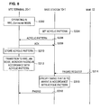
- FIG. 8 is a sequence diagram showing an operation of the first embodiment of the invention.
- FIG. 9 is a functional block diagram showing a configuration of a base station of a second embodiment of the invention.
- FIG. 10 is an explanatory diagram showing a specific example of paging by the base station of the second embodiment of the invention.
- FIG. 11 is a functional block diagram showing a configuration of an MTC terminal of the second embodiment of the invention.
- FIG. 12 is a sequence diagram showing an operation of the second embodiment of the invention.
- FIG. 13 is a functional block diagram showing a configuration of a base station of a third embodiment of the invention.
- FIG. 14 is an explanatory diagram showing a first notification method of a paging cycle.
- FIG. 15 is an explanatory diagram showing a second notification method of the paging cycle.
- FIG. 16 is a functional block diagram showing a configuration of an MTC terminal of the third embodiment of the invention.
- FIG. 17 is a sequence diagram showing an operation of the third embodiment of the invention.
- FIG. 18 is a sequence diagram showing an operation of the third embodiment of the invention.
- FIG. 19 is a functional block diagram showing a configuration of a base station of a fourth embodiment of the invention.
- FIG. 20 is an explanatory diagram showing a specific example of paging by the base station of the fourth embodiment of the invention.
- FIG. 21 is a functional block diagram showing a configuration of an MTC terminal of the fourth embodiment of the invention.
- FIG. 22 is an explanatory diagram showing a switch of a receiving cycle by the MTC terminal of the fourth embodiment of the invention.
- FIG. 23 is a sequence diagram showing an operation of the fourth embodiment of the invention.
- FIG. 24 is a functional block diagram showing a configuration of a base station of a fifth embodiment of the invention.
- FIG. 25 is an explanatory diagram showing a switch of a paging cycle by the base station of the fifth embodiment of the invention.
- FIG. 26 is an explanatory diagram showing a switch of the paging cycle by the base station of the fifth embodiment of the invention.
- FIG. 27 is a sequence diagram showing an operation of the fifth embodiment of the invention.
- the plurality of constituent features having substantially the same functional configuration may be distinguished as MTC terminals 20 A, 20 B, and 20 C.
- the respective one of the plurality of constituent features having substantially the same functional configuration does not need to be particularly distinguished, only the same reference sign will be given.
- the MTC terminals 20 A, 20 B, and 20 C do not particularly need to be distinguished, each will simply be termed a MTC terminal 20 .
- Embodiments of the invention can be adapted to the 4G radio communication system by way of examples, so an overview of the 4G radio communication system will be described.
- FIG. 1 is an explanatory diagram showing an example of a configuration of a radio communication system 1 .
- the radio communication system 1 includes a base station 10 , a core network including an MME (Mobility Management Entity) 12 , an S-GW (Serving Gateway) 14 , and a PDN (Packet Data Network)-GW 16 , MTC terminals 20 , and an MTC server 30 .
- MME Mobility Management Entity
- S-GW Serving Gateway
- PDN Packet Data Network
- Embodiments of the invention can be adapted to radio communication devices such as the base station 10 and the MTC terminals 20 shown in FIG. 1 .
- the base station 10 may for example be an eNodeB, a relay node, or a Home eNodeB that is a compact base station for home use.
- the MTC terminals 20 are examples of user equipment (UE), and adaptations to non-MTC terminals such as a cell phone, PC (Personal Computer), and the like is also possible as embodiments of the invention.
- UE user equipment
- the base station 10 is a radio base station that communicates with the MTC terminals 20 . Although only one base station 10 is shown in FIG. 1 , a large number of base stations 10 are connected to the core network in reality. Further, although depiction in FIG. 1 is omitted, the base station 10 communicates also with other user equipments such as a non-MTC terminal.
- the MME 12 is a device that performs controls of settings, opening, and hand-over of a data communication session.
- the MME 12 is connected to the base station 10 via an interface called X2.
- the S-GW 14 is a device that performs routing and transfer of user data.
- the PDN-GW 16 functions as a connecting node with an IP service network, and transfers the user data to and from the IP service network.
- the MTC terminals 20 are radio terminals specialized for MTC, which is a communication between machines and is not used directly by a human, which is under discussion in the 3GPP.
- the MTC terminals 20 perform radio communication in accordance with an application with the base station 10 . Further, the MTC terminals 20 perform bidirectional communication with the MTC server 30 via the core network.
- a case may be assumed in which an MTC terminal 20 collects electrocardiogram information of a human, and transmits the electrocardiogram information to the server by using uplink when a certain trigger condition is met.
- a case may be assumed in which a vending machine is caused to function as the MTC terminal 20 , and the MTC server 30 causes the vending machine under management to report sales once every certain cycle (for example, every 30 days).
- Such an MTC terminal 20 by way of example has the following features in general, however, not every MTC terminal 20 needs to have all of the following features, and which of the features is to be assigned depends on applications.
- FIG. 2 is an explanatory diagram showing a 4G frame format.
- a 10 ms radio frame is configured of ten 1 ms sub frames # 0 to # 9 .
- each 1 ms sub frame is configured of two 0.5 ms slots.
- each 0.5 ms slot is configured of seven Ofdm symbols.
- the Ofdm symbol is a unit used in a communication scheme of an OFDM (Orthogonal Frequency Division Multiplexing) modulation system, and is a unit by which data processed in one FFT (Fast Fourier Transform) is outputted.
- OFDM Orthogonal Frequency Division Multiplexing
- FFT Fast Fourier Transform
- a control signal called a PDCCH Physical Downlink Control Channel
- PDCCH Physical Downlink Control Channel
- One Ofdm symbol to three Ofdm symbols at the head of the sub frame are used for a transmission of the PDCCH. That is, there are cases in which one Ofdm symbol is used for the PDCCH transmission, and there also are cases in which three Ofdm symbols are used for the PDCCH transmission.
- a region in the radio frame used for the PDCCH transmission is called a control region, and a region in the radio frame used for transmissions of a PDSCH (Phy Downlink Shared Channel) or a PUSCH (Phy Uplink Shared Channel) is called a data region.
- a PDSCH Physical Downlink Shared Channel
- a PUSCH Physical Uplink Shared Channel
- an RRC_Connected mode and an RRC_Idle mode are defined.
- the RRC_Connected mode is a state in which a connection is established between the UE and the eNodeB, and the UE is capable of sending an uplink signal and receiving a downlink signal.
- the RRC_Idle mode is a state in which power of the UE is saved, and the UE in the RRC_Idle mode monitors the paging channel from the eNodeB, and transitions to the RRC_Connected mode when being called in the paging channel.
- the UE In the RRC_Idle mode, information of the UE does not exist in the eNodeB, and in which of tracking areas (paging areas) the UE exists is registered in an MME connected to the eNodeB by a wired connection called an S1-MME interface.
- the tracking areas are several tens to hundred eNodeBs that are in proximity, and the MME calls the UE by paging channel (incoming call) from all of the eNodeBs existing in the tracking area of the UE when a call is made to the UE.
- paging channel incoming call
- the UE of the RRC_Idle mode monitors the paging channel by performing a receiving process at a cycle by which the paging channel may be sent, and transition to the RRC_Connected mode when the call by the paging channel is made.
- the UE of the RRC_Idle mode stops clocks and power to a part of hardware so as to save power other than when it is in the receiving process for receiving the paging channels. Further, the UE of the RRC_Idle mode restarts power supply to the hardware before the time when the paging channels may be sent from the eNodeBs, performs the receiving process of the paging channels, and then again enters the state of saving power after the receiving process.
- a minimum unit of control information for each UE is called a CCE (Control Channel Element).
- the eNodeB sends the CCE including a PI (Paging Indicator) indicating which of resources in the PDSCH the UE should use to receive the paging channel in accordance with the PDSCH according to a predetermined cycle. That is, the CCE includes the receipt permission (grants) that is scheduling information.
- PI Paging Indicator
- the UE can acquire information notifying a presence of a downlink signal addressed to the UE itself by receiving the paging channel sent on the PDSCH indicated by the PI.
- a determination of whether the CCE is designated to the UE itself or not is performed by blind decoding to be described later.
- the PI is inserted in the PDCCH in accordance with the predetermined cycle when a paging channel for the UE is present (LTE The UMTS Long Term Evolution, Edited by: Stefania Sesia, Issam Toufik, Matthew Baker, 3.4 Paging, p. 77).
- This predetermined cycle is called a DRX (Discontinues reception) cycle, or a paging cycle, and is set for each UE.
- a paging cycle is set by a higher layer signaling such as signaling between the UE and the MME on a NAS (Non-Access Stratum) protocol.
- NAS Non-Access Stratum
- a P-RNTI for receiving a C-RNTI (Cell Radio Network Temporary Identify) that is an identifier of each UE and the paging channel is allotted to each UE.
- C-RNTI Cell Radio Network Temporary Identify
- the eNodeB adds check bits obtained by a CRC (Cyclic Redundancy Check) to the CCE while masking the control information such as the PI by a P-RNTI, in order to specify the destination of the CCE.
- the masking may be an exclusive OR (XOR) calculation of the control information and the P-RNTI, or may be a serial coupling of the control information and the P-RNTI.
- the UE When the PDCCH configured of a plurality of CCEs is received, the UE extracts the CCE identified by the UE's own P-RNTI by the blind decoding.
- the CCE identified by the UE's own P-RNTI by the blind decoding.
- FIG. 4 is an explanatory diagram showing the blind decoding.
- the UE performs a CRC check while demasking the respective CCEs by its own P-RNTI as the blind decoding. That is, the UE performs the CRC check of each CCE on the assumption that each CCE is addressed to the UE itself, and determines a CCE with a normal result is the CCE designated to the UE itself.
- the UE determines the CCE designated to the UE itself sent from the eNodeB, and can obtain the PI from the CCE designated to the UE itself.
- the MTC is required of a super low power consumption.
- An application by the MTC is expected with frequent data collection and settings once a week or once a month.
- an MTC terminal mounted on a vending machine is assumed to report sales in accordance with a monthly command from a data collecting center (MTC server).
- MTC server data collecting center
- the eNodeB is desired to send a paging (PI+paging channel) at different cycles such as thirty days, thirty-one days, twenty-nine days, and twenty-eight days, depending on a difference of days in each month. Accordingly, although a realization of acyclic paging cycles is important, in a current LTE that is based on paging cycles of an equal interval, it is difficult to comply with the acyclic paging cycles.
- paging can be used based on an acyclic pattern.
- FIG. 5 is a functional block diagram showing a configuration of a base station 10 - 1 of the first embodiment of the invention.
- the base station 10 - 1 of the first embodiment of the invention includes an antenna 104 , a radio communication section 108 , a scheduler 112 , a P-RNTI managing section 116 , a paging cycle managing section 121 , a storage section 131 , a paging control section 141 , and a CRC circuit 150 .
- the antenna 104 functions as a sending section that sends a sending signal, such as a PDCCH (control signal) and a PDSCH (data signal) supplied from the radio communication section 108 , as a radio signal, and a receiving section that supplies a radio signal, which is sent from a radio communication device such as an MTC terminal 20 of the first embodiment, to the radio communication section 108 by converting the radio signal into an electric receiving signal.
- a sending signal such as a PDCCH (control signal) and a PDSCH (data signal) supplied from the radio communication section 108
- a receiving section that supplies a radio signal, which is sent from a radio communication device such as an MTC terminal 20 of the first embodiment, to the radio communication section 108 by converting the radio signal into an electric receiving signal.
- a radio communication device such as an MTC terminal 20 of the first embodiment
- the base station 10 - 1 may include a plurality of antennas.
- the base station 10 is capable of realizing a MIMO (Multiple Input Multiple Out
- the radio communication section 108 performs a sending radio process such as modulation, DA conversion, filtering, amplification, up-conversion and the like of the sending signal such as PDCCH supplied from the paging control section 141 and PDSCH including user data supplied from a S-GW 14 . Further, the radio communication section 108 performs a receiving radio process such as down-conversion, filtering, DA conversion, demodulation and the like of the receiving signal supplied from the antenna 104 .
- a sending radio process such as modulation, DA conversion, filtering, amplification, up-conversion and the like of the sending signal such as PDCCH supplied from the paging control section 141 and PDSCH including user data supplied from a S-GW 14 .
- the radio communication section 108 performs a receiving radio process such as down-conversion, filtering, DA conversion, demodulation and the like of the receiving signal supplied from the antenna 104 .
- the P-RNTI managing section 116 manages the allotment of the P-RNTI to each MTC terminal 20 .
- the P-RNTI is used to identify a destination of a CCE including a PI.
- the paging cycle managing section 121 sets a paging cycle of each MTC terminal 20 during a non-connected period (during an RRC_Idle mode). More specifically, the paging cycle managing section 121 of the embodiment sets the paging cycle for sending the paging channel to a MTC terminal 20 - 1 of the first embodiment in a combination of two or more different intervals, that is, in an acyclic pattern. For example, the paging cycle managing section 121 normally sets the paging cycle at a 10 radio frame cycle, however, it sets the paging cycle in an acyclic pattern of “3, 5, 2, 9, . . . ”.
- this acyclic pattern is shared with the MTC terminal 20 - 1 , it is not realistic to set unlimited numbers of acyclic patterns as the paging cycle. Due to this, an iteration of the set acyclic pattern may be treated as the paging cycle.
- the paging cycle managing section 121 may set the acyclic pattern in accordance with an instruction from a network side, such as an MME 12 or an MTC server 30 . For example, in a case where a setting at a cycle that comes at an end of the month such as on 31st, 28th, 31st, and 30th is instructed from the network side, the paging cycle managing section 121 may set the acyclic pattern by converting the instructed cycles into radio frame units.
- the storage section 131 stores the acyclic pattern of each MTC terminal 20 set by the paging cycle managing section 121 .
- the paging control section 141 generates the CCE including the PI in a case where paging information (system information, incoming call and the like) to the MTC terminal 20 - 1 is present. More specifically, the paging control section 141 generates the PI, and the CCE that is obtained by the CRC circuit 150 by masking the PI by the P-RNTI of the MTC terminal 20 - 1 .
- the masking may be a calculation of an exclusive OR (XOR) of the PI and the P-RNTI, or may be a serial coupling of the PI and the P-RNTI. Due to this, the MTC terminal 20 - 1 to which the P-RNTI used in the masking is allotted can be designated as the destination of the PI.
- the CCE generated as above is supplied to the radio communication section 108 , and is mapped in the PDCCH.
- the paging control section 141 generates the paging channel including paging information.
- the paging channel is supplied to the radio communication section 108 , and is mapped in a resource on the PDSCH indicated by the PI.
- the paging information such as the incoming call is supplied via an S1-MME interface from the MME 12 that handles the control information such as the paging and a handover.
- the paging control section 141 of the embodiment controls the paging (sending of the PI and the paging channel) to the MTC terminal 20 - 1 in the RRC_Idle mode in radio frames in accordance with the acyclic pattern stored in the storage section 131 in connection to the MTC terminal 20 - 1 .
- sending of the PI and the paging channel sending of the PI and the paging channel
- FIG. 6 is an explanatory diagram showing a specific example of the paging by the base station 10 - 1 .
- the paging cycle becomes an iteration of the acyclic pattern as shown in FIG. 6 .
- the paging control section 141 of the base station 10 - 1 controls the paging in the radio frames that arrive in accordance with the acyclic pattern as shown in a square enclosure of “P” in FIG. 6 .
- the base station 10 - 1 of the first embodiment of the invention can set the acyclic pattern that arrives at the end of months such as 31st (January), 28th (February), 31st (March), 30th (April), . . . , for example, as the paging cycle. Due to this, since the base station 10 - 1 can perform the paging only at the end of the month when the data report needs to be made from the MTC terminal 20 - 1 , consumption amounts of radio resources and the MTC terminal 20 - 1 can be lessened compared to a case of predeterminedly setting the MTC terminal 20 - 1 to report data each time at the end of the months.
- FIG. 7 is a functional block diagram showing the configuration of the MTC terminal 20 - 1 of the first embodiment.
- the MTC terminal 20 - 1 of the first embodiment includes an antenna 204 , a radio communication section 208 , a receiving cycle control section 221 , a storage section 231 , a blind decoding section 240 , and a CRC circuit 250 .
- the antenna 204 functions as a sending section that sends a sending signal, such as a PUSCH (data signal) supplied from the radio communication section 208 , as a radio signal, and a receiving section that supplies radio signals such as PDCCH and PDSCH, which are sent from the base station 10 - 1 , to the radio communication section 208 by converting the radio signals into electric receiving signals.
- a sending signal such as a PUSCH (data signal) supplied from the radio communication section 208
- a receiving section that supplies radio signals such as PDCCH and PDSCH, which are sent from the base station 10 - 1 , to the radio communication section 208 by converting the radio signals into electric receiving signals.
- the MTC terminal 20 - 1 may include a plurality of antennas.
- the MTC terminal 20 - 1 is capable of realizing the MIMO (Multiple Input Multiple Output) communication, and the diversity communication and the like.
- MIMO Multiple Input Multiple Output
- the radio communication section 208 performs a sending radio process of modulation, DA conversion, filtering, amplification, up-conversion and the like of the user data supplied from a higher layer. Further, the radio communication section 208 performs a receiving radio process of down-conversion, filtering, DA conversion, demodulation and the like of the receiving signals supplied from the antenna 204 .
- the storage section 231 stores various types of information used in the communication with the base station 10 - 1 .
- the storage section 231 stores the P-RNTI allotted to the MTC terminal 20 - 1 by the P-RNTI managing section 116 of the base station 10 - 1 , the acyclic pattern set by the paging cycle managing section 121 of the base station 10 - 1 and the like.
- the receiving cycle control section 221 is a receipt control section that controls a receiving cycle (DRX cycle) for monitoring the paging in the RRC_Idle mode. More specifically, the receiving cycle control section 221 causes the blind decoding section 240 to perform blind decoding in accordance with the radio frames complying with the acyclic pattern stored in the storage section 231 .
- the blind decoding section 240 extracts the CCE identified by the P-RNTI given to the MTC terminal 20 - 1 by the blind decoding when the PDCCH is supplied from the radio communication section 208 .
- the blind decoding section 240 cooperates with the CRC circuit 250 to perform a CRC check by demasking each CCE by the P-RNTI given to the MTC terminal 20 - 1 . Then, the blind decoding section 240 extracts the CCE with a normal result, and supplies the resource on the PDSCH indicated by the PI described in the CCE as a decoded result to the radio communication section 208 .
- the radio communication section 208 can achieve the paging channel sent from the base station 10 - 1 b base station 10 - 1 by performing the receiving process on the resource on the PDSCH indicated by the decoded result.
- the MTC terminal 20 - 1 of the first embodiment can monitor the paging in accordance with the acyclic pattern set by the base station 10 - 1 .
- the MTC terminal 20 - 1 may set the acyclic pattern and notify the acyclic pattern to the base station 10 - 1 .
- FIG. 8 is a sequence diagram showing an operation of the first embodiment of the invention. As shown in FIG. 8 , in a state in which the MTC terminal 20 - 1 is operating in the RRC_Connected mode (S 302 ), when the base station 10 - 1 sets the acyclic pattern (S 304 ), the base station 10 - 1 notifies the acyclic pattern to the MTC terminal 20 - 1 (S 306 ).
- the MTC terminal 20 - 1 returns an ACK to the notification of the acyclic pattern to the base station 10 - 1 (S 308 ), and stores the acyclic pattern in the storage section 231 (S 310 ).
- the receiving cycle control section 221 causes the blind decoding section 240 to monitor the paging (PI) in accordance with the acyclic pattern stored in the storage section 231 (S 312 ).
- the base station 10 - 1 when a paging request is supplied from the MME 12 via the S1-MME interface (S 314 ), the base station 10 - 1 specifies a timing that arrives in accordance with the acyclic pattern set in S 304 (S 316 ), and performs paging at the specified timing (S 318 ).
- the MTC terminal 20 - 1 since the MTC terminal 20 - 1 is monitoring the paging at the acyclic pattern, the paging from the base station 10 - 1 can be achieved.
- a paging cycle can be switched among a plurality of cycles at a certain timing.
- FIG. 9 is a functional block diagram showing a configuration of a base station 10 - 2 of the second embodiment of the invention.
- the base station 10 - 2 of the second embodiment of the invention includes an antenna 104 , a radio communication section 108 , a scheduler 112 , a P-RNTI managing section 116 , a paging cycle managing section 122 , a storage section 132 , a paging control section 142 , and a CRC circuit 150 .
- the paging cycle managing section 122 sets a plurality of cycles for paging to each MTC terminal 20 - 2 operating in an RRC_Idle mode, and a switching timing of the plurality of cycles. For example, the paging cycle managing section 122 sets a long cycle, a short cycle, and the switching timing (time, or frame) of the long cycle and the short cycle.
- the cycle switching timing may be a time to switch the cycle, or a frame number and the like, or a duration time of the long cycle or the short cycle, or a continued frame number.
- the paging cycle managing section 122 may set each cycle switching timing by associating the cycle after the switch.
- the paging cycle managing section 122 may set a switching order of each cycle.
- the storage section 132 stores the plurality of cycles of each MTC terminal 20 set by the paging cycle managing section 122 , and information indicating the timing to switch the plurality of cycles.
- the paging control section 142 controls the paging to the MTC terminal 20 - 2 in the RRC_Idle mode in accordance with radio frames according to the plurality of cycles and the cycle switching timing stored in the storage section 132 in connection to the MTC terminal 20 - 2 .
- this feature will be described more specifically with reference to FIG. 10 .
- FIG. 10 is an explanatory diagram showing a specific example of the paging by the base station 10 - 2 .
- the paging control section 142 of the base station 10 - 2 switches the paging cycle from the short cycle to the long cycle at t 1 as shown in FIG. 10 . Further, the paging control section 142 switches the paging cycle from the long cycle to the short cycle at t 2 .
- the paging control section 142 of the base station 10 - 2 controls the paging by the radio frames that arrive in accordance with the switching of the long cycle and the short cycle as shown in a square enclosure of “P” in FIG. 10 .
- the base station 10 - 2 of the second embodiment of the invention can perform paging with less delay from an occurrence of a paging request at the end of months even if days in each month differ.
- the long cycle, the short cycle, and the cycle switching-timing can be shared between the base station 10 - 2 and the MTC terminal 20 - 2 . Due to this, compared to the first embodiment, an information amount of signaling from the base station 10 - 2 to the MTC terminal 20 - 2 can more easily be controlled.
- FIG. 11 is a functional block diagram showing the configuration of the MTC terminal 20 - 2 of the second embodiment.
- the MTC terminal 20 - 2 of the second embodiment includes an antenna 204 , a radio communication section 208 , a receiving cycle control section 222 , a storage section 232 , a blind decoding section 240 , and a CRC circuit 250 .
- Functions of the antenna 204 , the radio communication section 208 , the blind decoding section 240 , and the CRC circuit 250 are as described in the first embodiment, so hereinbelow, configurations differing from the first embodiment will primarily be described.
- the storage section 232 stores various types of information used in a communication with the base station 10 - 2 .
- the storage section 232 stores the P-RNTI allotted to the MTC terminal 20 - 2 by the P-RNTI managing section 116 of the base station 10 - 2 , and the long cycle, the short cycle, the cycle switching-timing and the like that are set by the paging cycle managing section 121 of the base station 10 - 2 .
- the receiving cycle control section 222 is a receipt control section that controls a receiving cycle (DRX cycle) for monitoring paging in an RRC_Idle mode. More specifically, the receiving cycle control section 222 causes the blind decoding section 240 to perform blind decoding with radio frames in accordance with the long cycle, the short cycle, and the cycle switching-timing stored in the storage section 232 .
- the MTC terminal 20 - 2 of the second embodiment can switch the receiving cycle among a plurality of cycles at the cycle switching-timing set by the base station 10 - 2 .
- the MTC terminal 20 - 2 may set the cycle switching-timing and notify the same to the base station 10 - 2 .
- the base station 10 - 2 does not have to notify the long cycle and the short cycle.
- FIG. 12 is a sequence diagram showing the operation of the second embodiment of the invention. As shown in FIG. 12 , in a state where the MTC terminal 20 - 2 is operating in an RRC_Connected mode (S 402 ), when the base station 10 - 2 sets the cycle switching-timing (S 404 ), the base station 10 - 2 notifies the cycle switching-timing to the MTC terminal 20 - 2 (S 406 ).
- the MTC terminal 20 - 2 sends an ACK responsive to the notification of the cycle switching-timing to the base station 10 - 2 (S 408 ), and stores the cycle switching-timing in the storage section 232 (S 410 ).
- the base station 10 - 2 may notify the plurality of cycles such as the long cycle and the short cycle, in addition to the cycle switching-timing.
- the receiving cycle control section 222 monitors paging in accordance with the long cycle or the short cycle, and switches the long cycle and the short cycle at the cycle switching-timing stored in the storage section 232 (S 412 ).
- the base station 10 - 2 when the paging request is supplied from an MME 12 via an S1-MME interface (S 414 ), the base station 10 - 2 specifies a timing that is to arrive in accordance with the long cycle or the short cycle that is switched at the cycle switching-timing set in S 404 (S 416 ), and performs paging at the specified timing (S 418 ).
- the MTC terminal 20 - 2 since the MTC terminal 20 - 2 is monitoring paging by switching the long cycle and the short cycle at the same cycle switching-timing as the base station 10 - 2 , the paging from the base station 10 - 2 can be acquired.
- a paging cycle can be sequentially updated.
- FIG. 13 is a functional block diagram showing the configuration of a base station 10 - 3 of the third embodiment of the invention.
- the base station 10 - 3 of the third embodiment of the invention includes an antenna 104 , a radio communication section 108 , a scheduler 112 , a P-RNTI managing section 116 , a paging cycle managing section 123 , a storage section 133 , a paging control section 143 , and a CRC circuit 150 .
- the paging cycle managing section 123 sequentially updates the paging cycle for paging an MTC terminal 20 - 3 operating in an RRC_Idle mode. For example, the paging cycle managing section 123 updates the paging cycle to a cycle B when the paging cycle is of a cycle A.
- the storage section 133 stores the paging cycle (sequentially updated cycle) sequentially updated by the paging cycle managing section 123 .
- the paging control section 143 controls the paging to the MTC terminal 20 - 3 in the RRC_Idle mode with radio frames in accordance with the sequentially updated cycle stored in the storage section 133 .
- the paging cycle updated by the paging cycle managing section 123 needs to be notified to the MTC terminal 20 - 3 as well, as a notification method of the paging cycle, a first notification method described with reference to FIG. 14 and a second notification method described with reference to FIG. 15 may be exemplified.
- FIG. 14 is an explanatory diagram showing the first notification method of the paging cycle.
- the base station 10 - 3 may notify the paging cycle as below in all of paging channels. For example, as shown in FIG. 14 , the base station 10 - 3 may notify the cycle A in a paging channel # 11 where the cycle A continues to take place thereafter, and may notify the cycle B in a paging channel # 12 where the paging cycle is to be updated to the cycle B thereafter
- FIG. 15 is an explanatory diagram showing the second notification method of the paging cycle.
- the base station 10 - 3 may notify the updated paging cycle in the paging channel where the paging cycle is to be updated thereafter.
- the base station 10 - 3 may not notify the paging cycle in the paging channel # 11 where the cycle A continues to take place thereafter, and may notify the cycle B in the paging channel # 12 in which the paging cycle is updated to the cycle B.
- the third embodiment of the invention it is possible to sequentially update the paging cycle related to the MTC terminal 20 - 3 operating in the RRC_Idle mode responsive to an update request of the paging cycle on a network side including the base station 10 - 3 . Further, according to the third embodiment of the invention, since there is no need to share an acyclic pattern configured of a plurality of intervals as in the first embodiment, it is advantageous in the viewpoint of memory resources. Further, especially the second notification method is effective in that it can suppress resources for the notification.
- FIG. 16 is a functional block diagram showing the configuration of the MTC terminal 20 - 3 of the third embodiment.
- the MTC terminal 20 - 3 of the third embodiment includes an antenna 204 , a radio communication section 208 , a receiving cycle control section 223 , a storage section 233 , a blind decoding section 240 , and a CRC circuit 250 .
- Functions of the antenna 204 , the radio communication section 208 , the blind decoding section 240 , and the CRC circuit 250 are as described in the first embodiment, so hereinbelow, configurations differing from the first embodiment will primarily be described.
- the storage section 233 stores various types of information used in a communication with the base station 10 - 3 .
- the storage section 233 stores a P-RNTI allotted to the MTC terminal 20 - 3 by a P-RNTI managing section 116 of the base station 10 - 3 , and a paging cycle that is sequentially updated by a paging cycle managing section 121 of the base station 10 - 3 , and the like.
- the receiving cycle control section 223 is a receipt control section that controls a receiving cycle (DRX cycle) for monitoring paging in an RRC_Idle mode. More specifically, the receiving cycle control section 223 causes the blind decoding section 240 to perform blind decoding with radio frames in accordance with the sequentially updated paging cycle stored in the storage section 233 .
- the MTC terminal 20 - 3 of the third embodiment can monitor the paging in accordance with the paging cycle that is sequentially updated by the base station 10 - 3 .
- FIG. 17 is a sequence diagram showing an operation of the third embodiment of the invention. As shown in FIG. 17 , in a state where the MTC terminal 20 - 3 is operating in an RRC_Connected mode (S 502 ), when the base station 10 - 3 sets the paging cycle (S 504 ), the base station 10 - 3 notifies the paging cycle to the MTC terminal 20 - 3 (S 506 ).
- the MTC terminal 20 - 3 sends an ACK responsive to the notification of the paging cycle to the base station 10 - 3 (S 508 ), and stores the paging cycle in the storage section 233 (S 510 ).
- the receiving cycle control section 223 monitors paging in accordance with the paging cycle stored in the storage section 233 (S 512 ).
- the base station 10 - 3 specifies a timing that is to arrive in accordance with the paging cycle set in S 504 (S 516 ). Further, in the case of updating the paging cycle, the base station 10 - 3 writes an updated paging cycle in the paging channel (S 518 ). Then, the base station 10 - 3 performs paging at the timing specified in S 516 by the paging channel in which the updated paging cycle is written (S 520 ).
- the MTC terminal 20 - 3 When the paging channel in which the updated paging cycle is written is received, the MTC terminal 20 - 3 stores the updated paging cycle in the storage section 233 , and monitors the paging in accordance with the updated paging cycle (S 522 ).
- the base station 10 - 3 sequentially updates the paging cycle and notifies the same to the MTC terminal 20 - 3 as described above, it is important for the base station 10 - 3 to know whether the notification of the updated paging cycle has been correctly received by the MTC terminal 20 - 3 or not.
- the MTC terminal 20 - 3 sends a receipt confirmation by an uplink, there is a problem that signaling is increased.
- the base station 10 - 3 of the embodiment solves the above problem by a method described hereinbelow with reference to FIG. 18 .
- FIG. 18 is a sequence diagram showing an operation of the third embodiment.
- the base station 10 - 3 performs paging by writing the updated paging cycle in the paging channel (S 532 , S 534 ). Thereafter, the base station 10 - 3 transitions to the updated paging cycle, and in a case where a terminal is called by an incoming call in a first paging channel (S 536 , S 538 ), it determines presence and absence of a response from the MTC terminal 20 - 3 to the incoming call (S 540 ).
- the base station 10 - 3 returns the paging cycle to the paging cycle before the update (S 542 ). According to such a configuration, the base station 10 - 3 becomes capable of performing the paging at a cycle that is monitored by the MTC terminal 20 - 3 .
- a state of the UE may change among the cycle intervals.
- performing signaling for changing the paging cycle by the UE transitioning to an RRC_Connected mode and performing synchronization with an eNodeB may be considered, such a method was problematic in that power is consumed therein.
- An MTC terminal 20 - 4 of the fourth embodiment of the invention is capable of changing the paging cycle in accordance with the change in the state while maintaining the RRC_Idle mode.
- RRC_Idle mode a fourth embodiment of the invention will be described in detail.
- FIG. 19 is a functional block diagram showing a configuration of a base station 10 - 4 of the fourth embodiment of the invention.
- the base station 10 - 4 of the fourth embodiment of the invention includes an antenna 104 , a radio communication section 108 , a scheduler 112 , a P-RNTI managing section 116 , a paging cycle managing section 124 , a storage section 134 , a paging control section 144 , and a CRC circuit 150 .
- the paging cycle managing section 124 sets a plurality of cycles for paging to each MTC terminal 20 - 4 operating in the RRC_Idle mode. For example, the paging cycle managing section 124 sets a long cycle and a short cycle.
- the storage section 134 stores information indicating the plurality of cycles (the long cycle and the short cycle) of each MTC terminal 20 - 4 set by the paging cycle managing section 124 .
- the paging control section 144 controls the paging to the MTC terminal 20 - 4 in the RRC_Idle mode by radio frames in accordance with each of the plurality of cycles stored in the storage section 134 in connection to the MTC terminal 20 - 4 .
- this respect will be described in detail with reference to FIG. 20 .
- FIG. 20 is an explanatory diagram showing a specific example of the paging by the base station 10 - 4 .
- the long cycle and the short cycle are stored in the storage section 134 in connection to the MTC terminal 20 - 4 , and a case in which the base station 10 - 4 receives a paging request to the MTC terminal 20 - 4 from an MME 12 at t 4 as shown in FIG. 20 will be considered.
- the paging cycle managing section 124 of the base station 10 - 4 performs the paging to the MTC terminal 20 - 4 at both a timing in accordance with the short cycle and a timing in accordance with the long cycle.
- FIG. 21 is a functional block diagram showing the configuration of the MTC terminal 20 - 4 of the fourth embodiment.
- the MTC terminal 20 - 4 of the fourth embodiment includes an antenna 204 , a radio communication section 208 , a receiving cycle control section 224 , a storage section 234 , a blind decoding section 240 , a CRC circuit 250 , and a state detecting section 260 .
- Functions of the antenna 204 , the radio communication section 208 , the blind decoding section 240 , and the CRC circuit 250 are as described in the first embodiment, so hereinbelow, configurations differing from the first embodiment will primarily be described.
- the storage section 234 stores various types of information used in a communication with a base station 10 - 4 .
- the storage section 234 stores a P-RNTI allotted to the MTC terminal 20 - 4 by a P-RNTI managing section 116 of the base station 10 - 4 , and a long cycle, a short cycle and the like set by a paging cycle managing section 124 of the base station 10 - 4 .
- the state detecting section 260 detects a state change of the MTC terminal 20 - 4 .
- the state detecting section 260 may be a velocity sensor or a GPS that detects a movement of the MTC terminal 20 - 4 , or that the MTC terminal 20 - 4 has moved to a predetermined position as the state change.
- the state detecting section 260 may detect a decrease in a remaining power of the MTC terminal 20 - 4 (for example, detect that the remaining power has gone below a threshold) as the state change. Further, in a case where the MTC terminal 20 - 4 is mounted to an apparatus having a function of a vending machine of products, the state detecting section 260 may detect change in sales by the vending machine function or a decrease in product stocks as the state change.
- the receiving cycle control section 224 is a receipt control section that controls a receiving cycle (DRX cycle) for monitoring paging in the RRC_Idle mode.
- DRX cycle a receiving cycle for monitoring paging in the RRC_Idle mode.
- a meaning to have the MTC terminal 20 - 4 report the stocks is small if the stocks have not changed at all.
- the receiving cycle control section 224 of the MTC terminal 20 - 4 of the embodiment switches the receiving cycle between the long cycle and the short cycle depending on a detection of the state change by the state detecting section 260 . Even if the MTC terminal 20 - 4 one sidedly changes the receiving cycle for paging as above, since the base station 10 - 4 of the embodiment performs the paging to the MTC terminal 20 - 4 at both the timing in accordance with the short cycle and the timing in accordance with the long cycle as described above with reference to FIG. 20 , the MTC terminal 20 - 4 can receive the paging from the base station 10 - 4 .
- this feature will be described more specifically with reference to FIG. 22 .
- FIG. 22 is an explanatory diagram showing switching of the receiving cycle by the MTC terminal 20 - 4 .
- the receiving cycle control section 224 of the MTC terminal 20 - 4 switches the receiving cycle from the long cycle to the short cycle.
- the base station 10 - 4 performs the paging at both the timing in accordance with the short cycle and the timing in accordance with the long cycle. Due to this, the MTC terminal 20 - 4 can receive the paging that is performed at the timing in accordance with the short cycle from the base station 10 - 4 after having switched the receiving cycle.
- the MTC terminal 20 - 4 monitors in accordance with the long cycle when there is no transportation of the cargo, and reports the same positional information.
- the receiving cycle control section 224 of the MTC terminal 20 - 4 switches the receiving cycle to the short cycle.
- the receiving cycle control section 224 of the MTC terminal 20 - 4 may switch the receiving cycle to the short cycle when the cargo has moved to a specific location.
- the receiving cycle control section 224 of the MTC terminal 20 - 4 may switch the receiving cycle from the short cycle to the long cycle. According to such a configuration, a decreasing speed of the remaining power of the MTC terminal 20 - 4 can be suppressed.
- the receiving cycle control section 224 of the MTC terminal 20 - 4 may switch the receiving cycle from the long cycle to the short cycle. According to such a configuration, the network side can acquire useful information with less delay.
- FIG. 23 is a sequence diagram showing an operation of the fourth embodiment of the invention. As shown in FIG. 23 , in the state in which the MTC terminal 20 - 4 is operating in the RRC_Connected mode (S 602 ), the base station 10 - 4 sets the long cycle and the short cycle (S 604 ), and notifies the long cycle and the short cycle to the MTC terminal 20 - 4 (S 606 ).
- the MTC terminal 20 - 4 returns an ACK to the base station 10 - 4 in response to the notification of the long cycle and the short cycle (S 608 ), and stores information indicating the long cycle and the short cycle in the storage section 234 (S 610 ).
- the receiving cycle control section 224 monitors paging in accordance with the long cycle stored in the storage section 234 (S 612 ). Notably, the receiving cycle control section 224 may set the receiving cycle just after having transitioned to the RRC_Idle mode in the short cycle.
- the base station 10 - 4 when the paging request is supplied from the MME 12 via the S1-MME interface (S 614 ), the base station 10 - 4 specifies a timing in accordance with the long cycle and a timing in accordance with the short cycle (S 616 ), and performs paging at both of the timings (S 618 , S 620 ).
- the MTC terminal 20 - 4 since the MTC terminal 20 - 4 is monitoring the paging in accordance with the long cycle, it can acquire the paging at the timing according to the long cycle (S 620 ).
- the receiving cycle control section 224 of the MTC terminal 20 - 4 switches the receiving cycle from the long cycle to the short cycle (S 624 ).
- the base station 10 - 4 specifies the timing in accordance with the long cycle and the timing in accordance with the short cycle (S 628 ), and performs the paging at both of the timings (S 630 , S 632 ).
- the MTC terminal 20 - 4 since the MTC terminal 20 - 4 is monitoring the paging in accordance with the short cycle, it can acquire the paging at the timing according to the short cycle (S 630 ).
- the fifth embodiment of the invention is made in view of the same problem as the fourth embodiment of the invention, and an MTC terminal 20 - 5 of the fifth embodiment of the invention is capable of changing a paging cycle in accordance with a state change while maintaining an RRC_Idle mode.
- an MTC terminal 20 - 5 of the fifth embodiment of the invention is capable of changing a paging cycle in accordance with a state change while maintaining an RRC_Idle mode.
- functional blocks of the MTC terminal 20 - 5 of the fifth embodiment can be configured substantially identical to the functional blocks of the MTC terminal 20 - 4 of the fourth embodiment, so a detailed description thereof will be omitted.
- FIG. 24 is a functional block diagram showing the configuration of a base station 10 - 5 of the fifth embodiment of the invention.
- the base station 10 - 5 of the fifth embodiment of the invention includes an antenna 104 , a radio communication section 108 , a scheduler 112 , a P-RNTI managing section 116 , a paging cycle managing section 125 , a storage section 135 , a paging control section 145 , and a CRC circuit 150 .
- the paging cycle managing section 125 sets a plurality of cycles for paging each MTC terminal 20 - 5 operating in an RRC_Idle mode. For example, the paging cycle managing section 125 sets a long cycle and a short cycle.
- the storage section 135 stores information indicating the plurality of cycles (long cycle and short cycle) of each MTC terminal 20 - 5 set by the paging cycle managing section 125 .
- the paging control section 145 controls the paging to the MTC terminal 20 - 5 in the RRC_Idle mode by radio frames in accordance with one of the plurality of cycles stored in the storage section 135 in connection to the MTC terminal 20 - 5 .
- the MTC terminal 20 - 5 of the fifth embodiment switches a receiving cycle for the paging according to the state change of the MTC terminal 20 - 5 , similar to the fourth embodiment.
- a base station 10 - 5 performs paging in accordance with a cycle before the switch by the MTC terminal 20 - 5 , even after the switch of the receiving cycle by the MTC terminal 20 - 5 . Due to this, since the MTC terminal 20 - 5 cannot receive the paging, the base station 10 - 5 cannot receive a response to the paging from the MTC terminal 20 - 5 .
- the base station 10 - 5 determines that the MTC terminal 20 - 5 has switched the receiving cycle, and switches the paging cycle for the MTC terminal 20 - 5 .
- this feature will be described specifically with reference to FIG. 25 and FIG. 26 .
- FIG. 25 is an explanatory diagram showing a switch of the paging cycle by the base station 10 - 5 .
- the MTC terminal 20 - 5 receives this paging # 21 .
- the MTC terminal 20 - 5 can no longer receive a paging # 22 that the base station 10 - 5 sends in accordance with the long cycle. Due to this, the paging control section 145 of the base station 10 - 5 determines that the MTC terminal 20 - 5 has switched the receiving cycle since a response to the paging # 22 cannot be obtained, switches the paging cycle to the short cycle and sends a paging # 22 ′. Since the MTC terminal 20 - 5 is monitoring the paging in accordance with the short cycle, it is possible to receive this paging # 22 ′.
- the base station 10 - 5 switches the paging cycle from the long cycle to the short cycle, although time from being called to the response will not be shortened, since the paging is sent in accordance with the long cycle until when it is necessary, there is an advantage in that resources for the paging can be saved.
- a plurality of MTC terminals 20 - 5 belongs to one P-RNTI.
- the plurality of MTC terminals 20 - 5 belonging to the same P-RNTI may include both MTC terminals 20 - 5 operating in the long cycle and MTC terminals 20 - 5 operating in the short cycle. Due to this, the base station 10 - 5 may perform the paging to different MTC terminals 20 - 5 by using the same P-RNTI at both the timing in accordance with the short cycle and the timing in accordance with the long cycle.
- the MTC terminal 20 - 5 can receive the paging sent in accordance with the long cycle even after having switched to the short cycle in regards to the timing. However, in this case, it becomes difficult for the base station 10 - 5 to determine the switch in the receiving cycle of the MTC terminal 20 - 5 .
- the base station 10 - 5 may allot a P-RNTI for the long cycle and a P-RNTI for the short cycle to each MTC terminal 20 - 5 , and may use the P-RNTI for the long cycle upon performing the paging in accordance with the long cycle, and the P-RNTI for the short cycle upon performing the paging in accordance with the short cycle. Further, the MTC terminal 20 - 5 may perform blind decoding using the P-RNTI for the long cycle upon monitoring the paging in the long cycle, and perform the blind decoding using the P-RNTI for the short cycle upon monitoring the paging in the short cycle. According to such a configuration, it becomes possible for the base station 10 - 5 to determine the switch in the receiving cycle of the MTC terminal 20 - 5 at a high accuracy.
- FIG. 26 is an explanatory diagram showing the switch of the paging cycle by the base station 10 - 5 .
- the MTC terminal 20 - 5 receives a paging # 31 when the base station 10 - 5 sends the paging # 31 in accordance with the short cycle.
- a paging # 32 that the base station 10 - 5 sends in accordance with the short cycle can no longer be received by the MTC terminal 20 - 5 . Due to this, the paging control section 145 of the base station 10 - 5 determines that the MTC terminal 20 - 5 has switched the receiving cycle since a response to the paging # 32 cannot be obtained, switches the paging cycle to the long cycle and sends a paging # 32 ′. Since the MTC terminal 20 - 5 is monitoring the paging in accordance with the long cycle, it is possible to receive this paging # 32 ′.
- the MTC terminal 20 - 5 switching the receiving cycle from the short cycle to the long cycle, consumed power of the MTC terminal 20 - 5 can be reduced.
- consumed power of the MTC terminal 20 - 5 can be reduced.
- an undesirable influence therefrom is small since the MTC terminal 20 - 5 switches the monitoring cycle of the paging to the long cycle in cases where no problem is expected even if the response is delayed.
- FIG. 27 is a sequence diagram showing an operation of the fifth embodiment of the invention. As shown in FIG. 27 , in a state where the MTC terminal 20 - 5 is operating in the RRC_Connected mode (S 702 ), the base station 10 - 5 sets the long cycle and the short cycle (S 704 ), and notifies the long cycle and the short cycle to the MTC terminal 20 - 5 (S 706 ).
- the MTC terminal 20 - 5 returns an ACK responsive to the notification of the long cycle and the short cycle to the base station 10 - 5 (S 708 ), and stores information indicating the long cycle and the short cycle in the storage section 234 (S 710 ).
- the receiving cycle control section 224 monitors the paging in accordance with the long cycle stored in the storage section 234 (S 712 ). Notably, the receiving cycle control section 224 may set the receiving cycle just after having transitioned to the RRC_Idle mode in the short cycle.
- the base station 10 - 5 when a paging request is supplied from the MME 12 via the S1-MME interface (S 714 ), the base station 10 - 5 specifies a timing in accordance with the long cycle (S 716 ), and performs the paging at the specified timing (S 718 ).
- the MTC terminal 20 - 5 since the MTC terminal 20 - 5 is monitoring the paging in accordance with the long cycle, the paging from the base station 10 - 5 can be acquired (S 720 ).
- the receiving cycle control section 224 of the MTC terminal 20 - 5 switches the receiving cycle from the long cycle to the short cycle (S 722 ).
- the base station 10 - 5 specifies a timing in accordance with the long cycle (S 726 ), and performs the paging at the specified timing (S 728 ).
- the base station 10 - 5 cannot acquire the response to this paging.
- the paging control section 145 of the base station 10 - 5 determines that the MTC terminal 20 - 5 has switched the receiving cycle, and performs the paging by switching the paging cycle to the short cycle (S 730 , S 732 ).
- the MTC terminal 20 - 5 is monitoring the paging in accordance with the short cycle, the paging sent in S 732 can be acquired.
- the base station 10 it becomes possible for the base station 10 to perform the paging by switching the plurality of cycles.
- the base station 10 - 1 of the first embodiment can perform the paging in accordance with the acyclic pattern in which the end of the months such as 31st, (January), 28th (February), 31st (March), 30th (April), and so on arrives.
- the MTC terminal 20 - 4 of the fourth embodiment can switch the receiving cycle of the paging for example in accordance with the state change of the MTC terminal 20 - 4 without having have to communicate with the base station 10 - 4 in advance.
- the base station 10 may retain a plurality of sets of acyclic patterns and perform the paging at timing s in accordance with respective ones of the plurality of sets of acyclic patterns, and the MTC terminal 20 may switch the acyclic pattern for monitoring the paging in accordance with the state change.
- respective steps in the processes by the base station 10 and the MTC terminal 20 in the description do not necessarily be performed in chronological orders as described in sequence diagrams.
- the respective steps in the processes by the base station 10 and the MTC terminal 20 may be performed in orders different from the orders described the in sequence diagrams, or may be performed in parallel.
- computer programs for causing hardware such as CPUs, ROMs, and RAMs installed in the base station 10 and the MTC terminal 20 to exhibit similar functions as the respective configurations of the base station 10 and the MTC terminal 20 may be produced. Further, storage media storing such computer programs may also be provided.
Abstract
Description
- Patent Literature 1: JP H09-83427 A
-
- 1-1. Overview of radio communication system
- 1-2. Configuration of frame
- 1-3. Paging
- 1-4. Detailed description of paging channel
- 1-5. Blind decoding
- 1-6. Paging expected in MTC
-
- 2-1. First embodiment
- (Configuration of base station of the first embodiment)
- (Configuration of MTC terminal of the first embodiment)
- (Operation of the first embodiment)
- 2-2. Second embodiment
- (Configuration of base station of the second embodiment)
- (Configuration of MTC terminal of the second embodiment)
- (Operation of the second embodiment)
- 2-3. Third embodiment
- (Configuration of base station of the third embodiment)
- (Configuration of MTC terminal of the third embodiment)
- (Operation of the third embodiment)
- 2-4. Fourth embodiment
- (Configuration of base station of the fourth embodiment)
- (Configuration of MTC terminal of the fourth embodiment)
- (Operation of the fourth embodiment)
- 2-5. Fifth embodiment
- (Configuration of base station of the fifth embodiment)
- (Operation of the fifth embodiment)
- 2-1. First embodiment
- 10 Base station
- 12 MME
- 14 S-GW
- 20 MTC terminal
- 104, 204 Antenna
- 108, 208 Radio communication section
- 112 Scheduler
- 116 P-RNTI managing section
- 121 to 125 Paging cycle managing section
- 131 to 135, 231 to 234 Storage section
- 141 to 145 Paging control section
- 150 CRC circuit
- 221 to 224 Receiving cycle control section
- 240 Blind decoding section
- 250 CRC circuit
- 260 State detecting section
Claims (15)
Applications Claiming Priority (3)
| Application Number | Priority Date | Filing Date | Title |
|---|---|---|---|
| JP2011030657A JP5672046B2 (en) | 2011-02-16 | 2011-02-16 | Wireless communication apparatus, base station, wireless communication method, program, and wireless communication system |
| JP2011-030657 | 2011-12-28 | ||
| PCT/JP2012/052741 WO2012111482A1 (en) | 2011-02-16 | 2012-02-07 | Wireless communication apparatus, base station, wireless communication method, program, and wireless communication system |
Related Parent Applications (1)
| Application Number | Title | Priority Date | Filing Date |
|---|---|---|---|
| PCT/JP2012/052741 A-371-Of-International WO2012111482A1 (en) | 2011-02-16 | 2012-02-07 | Wireless communication apparatus, base station, wireless communication method, program, and wireless communication system |
Related Child Applications (1)
| Application Number | Title | Priority Date | Filing Date |
|---|---|---|---|
| US14/940,904 Continuation US9344996B2 (en) | 2011-02-16 | 2015-11-13 | Radio communication device, base station, method for radio communication, program and radio communication system |
Publications (2)
| Publication Number | Publication Date |
|---|---|
| US20130288720A1 US20130288720A1 (en) | 2013-10-31 |
| US9210686B2 true US9210686B2 (en) | 2015-12-08 |
Family
ID=46672410
Family Applications (2)
| Application Number | Title | Priority Date | Filing Date |
|---|---|---|---|
| US13/978,749 Active 2032-03-01 US9210686B2 (en) | 2011-02-16 | 2012-02-07 | Radio communication device, base station, method for radio communication, program and radio communication system |
| US14/940,904 Active US9344996B2 (en) | 2011-02-16 | 2015-11-13 | Radio communication device, base station, method for radio communication, program and radio communication system |
Family Applications After (1)
| Application Number | Title | Priority Date | Filing Date |
|---|---|---|---|
| US14/940,904 Active US9344996B2 (en) | 2011-02-16 | 2015-11-13 | Radio communication device, base station, method for radio communication, program and radio communication system |
Country Status (12)
| Country | Link |
|---|---|
| US (2) | US9210686B2 (en) |
| EP (1) | EP2677817B1 (en) |
| JP (1) | JP5672046B2 (en) |
| KR (1) | KR101867117B1 (en) |
| CN (1) | CN103583069B (en) |
| AU (1) | AU2012218698B2 (en) |
| BR (1) | BR112013020398A2 (en) |
| CA (1) | CA2823936A1 (en) |
| MX (1) | MX336163B (en) |
| RU (1) | RU2577538C2 (en) |
| WO (1) | WO2012111482A1 (en) |
| ZA (1) | ZA201305993B (en) |
Cited By (1)
| Publication number | Priority date | Publication date | Assignee | Title |
|---|---|---|---|---|
| US11805494B2 (en) * | 2021-01-14 | 2023-10-31 | Qualcomm Incorporated | Paging early indication techniques |
Families Citing this family (16)
| Publication number | Priority date | Publication date | Assignee | Title |
|---|---|---|---|---|
| US20140126548A1 (en) * | 2012-11-05 | 2014-05-08 | Qualcomm Incorporated | Dynamic paging channel selection in a machine-to-machine wireless wide area network |
| US20140146795A1 (en) * | 2012-11-26 | 2014-05-29 | Qualcomm Incorporated | Flexible paging scheme in a machine-to-machine wireless wide area network |
| US9351250B2 (en) * | 2013-01-31 | 2016-05-24 | Qualcomm Incorporated | Methods and apparatus for low power wake up signal and operations for WLAN |
| JP6102324B2 (en) * | 2013-02-20 | 2017-03-29 | 株式会社デンソー | Communications system |
| GB2514117A (en) * | 2013-05-13 | 2014-11-19 | Nec Corp | Communication system |
| EP3120633A4 (en) * | 2014-03-21 | 2017-03-22 | Telefonaktiebolaget LM Ericsson (publ) | Methods and arrangements regarding paging of wireless communication devices of a certain category |
| CN106465352B (en) | 2014-06-06 | 2019-11-08 | 诺基亚技术有限公司 | Control channel for paging message coverage enhancement is transmitted |
| CN106538033B (en) * | 2014-07-18 | 2019-11-26 | 华为技术有限公司 | User apparatus, network node and its method |
| CN105898867A (en) * | 2014-08-28 | 2016-08-24 | 阿尔卡特朗讯 | Paging method and device for coverage range enhanced MTC UE |
| EP3435732B1 (en) * | 2016-03-24 | 2021-12-29 | NTT DoCoMo, Inc. | Wireless base station and communication control method |
| JP2018078659A (en) * | 2018-02-09 | 2018-05-17 | ノキア ソリューションズ アンド ネットワークス オサケユキチュア | Control channel transmission for paging message coverage enhancement |
| JP6679658B2 (en) * | 2018-06-01 | 2020-04-15 | ソニー株式会社 | Mobile terminal, system and method for protocol mode switching |
| CN109548193B (en) * | 2018-11-15 | 2020-05-26 | Oppo广东移动通信有限公司 | DRX period adjusting method and device, base station and readable storage medium |
| US11109344B2 (en) * | 2019-05-01 | 2021-08-31 | Lg Electronics Inc. | Start and stop of reception of downlink transmission based on paging |
| US11212770B2 (en) * | 2019-06-27 | 2021-12-28 | Qualcomm Incorporated | Techniques for configuring paging cycles |
| CN113473596A (en) * | 2020-03-30 | 2021-10-01 | 华为技术有限公司 | Paging method, device and system |
Citations (8)
| Publication number | Priority date | Publication date | Assignee | Title |
|---|---|---|---|---|
| JPH0983427A (en) | 1995-09-14 | 1997-03-28 | Toshiba Corp | Mobile communication system, mobile communication network used for the system and mobile communication equipment |
| JP2001168998A (en) | 1999-12-07 | 2001-06-22 | Tokyo Gas Co Ltd | Communication system |
| US20030114156A1 (en) * | 2001-12-18 | 2003-06-19 | Kinnavy Michael J. | Method and mobile station for enabling a preferred slot cycle |
| JP2004247801A (en) | 2003-02-12 | 2004-09-02 | Toshiba Corp | Mobile communication system, mobile switching station for the system, and mobile station for the system |
| US20050277429A1 (en) * | 2004-06-10 | 2005-12-15 | Rajiv Laroia | Efficient paging in a wireless communication system |
| US20080014969A1 (en) * | 2006-07-14 | 2008-01-17 | Rajiv Laroia | Method and apparatus for paging terminals in a wireless communication system |
| US20100191370A1 (en) * | 2009-01-14 | 2010-07-29 | Eon Corporation | Remotely monitoring field assets |
| US20100279676A1 (en) * | 2009-04-28 | 2010-11-04 | Motorola, Inc. | Paging in a Cellular Communication System |
Family Cites Families (18)
| Publication number | Priority date | Publication date | Assignee | Title |
|---|---|---|---|---|
| US7606601B2 (en) * | 2003-07-04 | 2009-10-20 | Lg Electronics Inc. | Fast call setup system and method in a mobile communications system |
| JP4230314B2 (en) * | 2003-08-28 | 2009-02-25 | 京セラ株式会社 | Mobile station |
| US7450975B2 (en) * | 2005-09-28 | 2008-11-11 | Motorola, Inc. | System and method for improving battery life of a mobile station |
| KR100648067B1 (en) * | 2005-12-10 | 2006-11-23 | 한국전자통신연구원 | Method for adaptive discontinuous reception based on extended paging indicator for improvement of power effective performance at mobile terminal on wcdma |
| EP1985137B1 (en) * | 2006-02-03 | 2018-05-09 | Vodafone Group PLC | Network and method for optimizing an estimation of mobility of a mobile terminal |
| US7760676B2 (en) * | 2006-06-20 | 2010-07-20 | Intel Corporation | Adaptive DRX cycle length based on available battery power |
| KR101404674B1 (en) * | 2007-06-15 | 2014-06-09 | 삼성전자주식회사 | Apparatus and method for operating idle mode in wireless communication system |
| US8588155B2 (en) * | 2007-10-23 | 2013-11-19 | Lg Electronics Inc. | Method of transmitting broadcasting information |
| JP4726938B2 (en) * | 2008-09-22 | 2011-07-20 | 京セラ株式会社 | Mobile station |
| CN101730205A (en) * | 2008-10-31 | 2010-06-09 | 大唐移动通信设备有限公司 | Method, system and device for updating paging DRX period of UE |
| CN101730154A (en) * | 2008-10-31 | 2010-06-09 | 大唐移动通信设备有限公司 | Method for allocating paging DRX period to UE, system and device thereof |
| EP2433454B1 (en) * | 2009-04-27 | 2014-08-06 | Telefonaktiebolaget LM Ericsson (publ) | Notifying user equipment of an upcoming change of system information in a radio communication network |
| US20100317374A1 (en) * | 2009-06-11 | 2010-12-16 | Yaron Alpert | Apparatus for and method of managing paging interval access on a mobile station |
| US8433345B2 (en) * | 2009-06-17 | 2013-04-30 | Samsung Electronics Co., Ltd | Methods and apparatus to support paging with less interference in multi-tier communication systems |
| CN201440212U (en) * | 2009-07-31 | 2010-04-21 | 红山科技(大连)有限公司 | Wireless monitoring device for vending machine |
| KR101617888B1 (en) * | 2010-01-08 | 2016-05-04 | 삼성전자주식회사 | Method and apparatus of paging for high power saving reception mode m2m/mtc device communication in a mobile communication system |
| USRE49879E1 (en) * | 2010-01-12 | 2024-03-19 | Samsung Electronics Co., Ltd. | Method and apparatus for supporting discontinuous reception operation in mobile communication system |
| KR101823475B1 (en) * | 2010-02-09 | 2018-01-30 | 엘지전자 주식회사 | Method of receiving and transmitting message in a mobile communication system using a mtc device and apparatus for the same |
-
2011
- 2011-02-16 JP JP2011030657A patent/JP5672046B2/en not_active Expired - Fee Related
-
2012
- 2012-02-07 KR KR1020137020957A patent/KR101867117B1/en active IP Right Grant
- 2012-02-07 US US13/978,749 patent/US9210686B2/en active Active
- 2012-02-07 MX MX2013009233A patent/MX336163B/en unknown
- 2012-02-07 RU RU2013137245/07A patent/RU2577538C2/en not_active IP Right Cessation
- 2012-02-07 CA CA2823936A patent/CA2823936A1/en not_active Abandoned
- 2012-02-07 CN CN201280008056.0A patent/CN103583069B/en active Active
- 2012-02-07 EP EP12746611.8A patent/EP2677817B1/en active Active
- 2012-02-07 AU AU2012218698A patent/AU2012218698B2/en not_active Ceased
- 2012-02-07 BR BR112013020398A patent/BR112013020398A2/en not_active Application Discontinuation
- 2012-02-07 WO PCT/JP2012/052741 patent/WO2012111482A1/en active Application Filing
-
2013
- 2013-08-08 ZA ZA2013/05993A patent/ZA201305993B/en unknown
-
2015
- 2015-11-13 US US14/940,904 patent/US9344996B2/en active Active
Patent Citations (8)
| Publication number | Priority date | Publication date | Assignee | Title |
|---|---|---|---|---|
| JPH0983427A (en) | 1995-09-14 | 1997-03-28 | Toshiba Corp | Mobile communication system, mobile communication network used for the system and mobile communication equipment |
| JP2001168998A (en) | 1999-12-07 | 2001-06-22 | Tokyo Gas Co Ltd | Communication system |
| US20030114156A1 (en) * | 2001-12-18 | 2003-06-19 | Kinnavy Michael J. | Method and mobile station for enabling a preferred slot cycle |
| JP2004247801A (en) | 2003-02-12 | 2004-09-02 | Toshiba Corp | Mobile communication system, mobile switching station for the system, and mobile station for the system |
| US20050277429A1 (en) * | 2004-06-10 | 2005-12-15 | Rajiv Laroia | Efficient paging in a wireless communication system |
| US20080014969A1 (en) * | 2006-07-14 | 2008-01-17 | Rajiv Laroia | Method and apparatus for paging terminals in a wireless communication system |
| US20100191370A1 (en) * | 2009-01-14 | 2010-07-29 | Eon Corporation | Remotely monitoring field assets |
| US20100279676A1 (en) * | 2009-04-28 | 2010-11-04 | Motorola, Inc. | Paging in a Cellular Communication System |
Non-Patent Citations (1)
| Title |
|---|
| Japanese Office Action issued Sep. 9, 2014, in Japan Patent Application No. 2011-030657. |
Cited By (1)
| Publication number | Priority date | Publication date | Assignee | Title |
|---|---|---|---|---|
| US11805494B2 (en) * | 2021-01-14 | 2023-10-31 | Qualcomm Incorporated | Paging early indication techniques |
Also Published As
| Publication number | Publication date |
|---|---|
| KR101867117B1 (en) | 2018-06-12 |
| EP2677817A1 (en) | 2013-12-25 |
| MX2013009233A (en) | 2013-08-29 |
| CN103583069A (en) | 2014-02-12 |
| JP2012169970A (en) | 2012-09-06 |
| JP5672046B2 (en) | 2015-02-18 |
| AU2012218698A1 (en) | 2013-07-11 |
| KR20140050575A (en) | 2014-04-29 |
| CA2823936A1 (en) | 2012-08-23 |
| MX336163B (en) | 2016-01-11 |
| RU2577538C2 (en) | 2016-03-20 |
| US20130288720A1 (en) | 2013-10-31 |
| AU2012218698B2 (en) | 2016-09-29 |
| EP2677817B1 (en) | 2018-08-15 |
| CN103583069B (en) | 2017-09-15 |
| EP2677817A4 (en) | 2016-04-06 |
| US9344996B2 (en) | 2016-05-17 |
| US20160073376A1 (en) | 2016-03-10 |
| RU2013137245A (en) | 2015-02-20 |
| ZA201305993B (en) | 2014-02-26 |
| BR112013020398A2 (en) | 2016-10-25 |
| WO2012111482A1 (en) | 2012-08-23 |
Similar Documents
| Publication | Publication Date | Title |
|---|---|---|
| US9930721B2 (en) | Radio communication device, base station, method for radio communication, and radio communication system with acyclic paging cycles | |
| US9344996B2 (en) | Radio communication device, base station, method for radio communication, program and radio communication system | |
| US11082946B2 (en) | Wireless device, a network node and methods therein for optimizing paging in a communications network | |
| US9088914B2 (en) | Wireless terminal, wireless communication method, and wireless communication system | |
| US11832337B2 (en) | Method and device for determining timer configuration | |
| US9521660B2 (en) | Base station, wireless communication method, and wireless communication system | |
| KR102360462B1 (en) | Method, device and communication system for transmitting and acquiring system information | |
| US10582452B2 (en) | Timer handling in communications | |
| CN111757498B (en) | Method and device for monitoring PDCCH | |
| JP2013055394A (en) | Communication device, communication method, communication system, and base station | |
| CN111587600B (en) | Method, apparatus, and computer-readable storage medium for communicating over multiple bandwidth portions | |
| CN113632585A (en) | Discontinuous reception configuration of terminal equipment | |
| US20220150869A1 (en) | Assignment of a second ue identity to adjust paging timing for ue for wireless network | |
| EP3298830A1 (en) | Method for managing enhanced physical downlink control channel, wireless communication network, computer programs and computer program products | |
| JP5915795B2 (en) | Wireless communication apparatus, base station, wireless communication method, program, and wireless communication system | |
| WO2020154855A1 (en) | Mobility enhancement of terminal device | |
| CN115176491A (en) | Adaptive measurement of cross-link interference | |
| US20230089297A1 (en) | Adjusting a user equipment activity timing based on multiple signal sources for wireless network |
Legal Events
| Date | Code | Title | Description |
|---|---|---|---|
| AS | Assignment |
Owner name: SONY CORPORATION, JAPAN Free format text: ASSIGNMENT OF ASSIGNORS INTEREST;ASSIGNOR:TAKANO, HIROAKI;REEL/FRAME:030757/0980 Effective date: 20130611 |
|
| STCF | Information on status: patent grant |
Free format text: PATENTED CASE |
|
| MAFP | Maintenance fee payment |
Free format text: PAYMENT OF MAINTENANCE FEE, 4TH YEAR, LARGE ENTITY (ORIGINAL EVENT CODE: M1551); ENTITY STATUS OF PATENT OWNER: LARGE ENTITY Year of fee payment: 4 |
|
| AS | Assignment |
Owner name: INTERDIGITAL VC HOLDINGS, INC., DELAWARE Free format text: ASSIGNMENT OF ASSIGNORS INTEREST;ASSIGNOR:SONY CORPORATION;REEL/FRAME:052045/0297 Effective date: 20190829 |
|
| AS | Assignment |
Owner name: CONVIDA WIRELESS, LLC, DELAWARE Free format text: ASSIGNMENT OF ASSIGNORS INTEREST;ASSIGNOR:INTERDIGITAL VC HOLDINGS, INC.;REEL/FRAME:052089/0654 Effective date: 20200226 |
|
| MAFP | Maintenance fee payment |
Free format text: PAYMENT OF MAINTENANCE FEE, 8TH YEAR, LARGE ENTITY (ORIGINAL EVENT CODE: M1552); ENTITY STATUS OF PATENT OWNER: LARGE ENTITY Year of fee payment: 8 |
|
| AS | Assignment |
Owner name: INTERDIGITAL PATENT HOLDINGS, INC., DELAWARE Free format text: ASSIGNMENT OF ASSIGNORS INTEREST;ASSIGNOR:CONVIDA WIRELESS, LLC;REEL/FRAME:065853/0222 Effective date: 20231005 |