US9200766B2 - Lighting fixture - Google Patents
Lighting fixture Download PDFInfo
- Publication number
- US9200766B2 US9200766B2 US14/141,666 US201314141666A US9200766B2 US 9200766 B2 US9200766 B2 US 9200766B2 US 201314141666 A US201314141666 A US 201314141666A US 9200766 B2 US9200766 B2 US 9200766B2
- Authority
- US
- United States
- Prior art keywords
- light emitting
- light
- emitting part
- lighting fixture
- emitting parts
- Prior art date
- Legal status (The legal status is an assumption and is not a legal conclusion. Google has not performed a legal analysis and makes no representation as to the accuracy of the status listed.)
- Active, expires
Links
Images


Classifications
-
- F21K9/56—
-
- F—MECHANICAL ENGINEERING; LIGHTING; HEATING; WEAPONS; BLASTING
- F21—LIGHTING
- F21S—NON-PORTABLE LIGHTING DEVICES; SYSTEMS THEREOF; VEHICLE LIGHTING DEVICES SPECIALLY ADAPTED FOR VEHICLE EXTERIORS
- F21S8/00—Lighting devices intended for fixed installation
- F21S8/02—Lighting devices intended for fixed installation of recess-mounted type, e.g. downlighters
- F21S8/026—Lighting devices intended for fixed installation of recess-mounted type, e.g. downlighters intended to be recessed in a ceiling or like overhead structure, e.g. suspended ceiling
-
- F—MECHANICAL ENGINEERING; LIGHTING; HEATING; WEAPONS; BLASTING
- F21—LIGHTING
- F21V—FUNCTIONAL FEATURES OR DETAILS OF LIGHTING DEVICES OR SYSTEMS THEREOF; STRUCTURAL COMBINATIONS OF LIGHTING DEVICES WITH OTHER ARTICLES, NOT OTHERWISE PROVIDED FOR
- F21V21/00—Supporting, suspending, or attaching arrangements for lighting devices; Hand grips
- F21V21/14—Adjustable mountings
- F21V21/30—Pivoted housings or frames
-
- F—MECHANICAL ENGINEERING; LIGHTING; HEATING; WEAPONS; BLASTING
- F21—LIGHTING
- F21V—FUNCTIONAL FEATURES OR DETAILS OF LIGHTING DEVICES OR SYSTEMS THEREOF; STRUCTURAL COMBINATIONS OF LIGHTING DEVICES WITH OTHER ARTICLES, NOT OTHERWISE PROVIDED FOR
- F21V23/00—Arrangement of electric circuit elements in or on lighting devices
- F21V23/003—Arrangement of electric circuit elements in or on lighting devices the elements being electronics drivers or controllers for operating the light source, e.g. for a LED array
-
- F21Y2101/02—
-
- F21Y2105/003—
-
- F—MECHANICAL ENGINEERING; LIGHTING; HEATING; WEAPONS; BLASTING
- F21—LIGHTING
- F21Y—INDEXING SCHEME ASSOCIATED WITH SUBCLASSES F21K, F21L, F21S and F21V, RELATING TO THE FORM OR THE KIND OF THE LIGHT SOURCES OR OF THE COLOUR OF THE LIGHT EMITTED
- F21Y2105/00—Planar light sources
- F21Y2105/10—Planar light sources comprising a two-dimensional array of point-like light-generating elements
- F21Y2105/12—Planar light sources comprising a two-dimensional array of point-like light-generating elements characterised by the geometrical disposition of the light-generating elements, e.g. arranging light-generating elements in differing patterns or densities
-
- F21Y2113/005—
-
- F—MECHANICAL ENGINEERING; LIGHTING; HEATING; WEAPONS; BLASTING
- F21—LIGHTING
- F21Y—INDEXING SCHEME ASSOCIATED WITH SUBCLASSES F21K, F21L, F21S and F21V, RELATING TO THE FORM OR THE KIND OF THE LIGHT SOURCES OR OF THE COLOUR OF THE LIGHT EMITTED
- F21Y2113/00—Combination of light sources
- F21Y2113/10—Combination of light sources of different colours
- F21Y2113/13—Combination of light sources of different colours comprising an assembly of point-like light sources
-
- F—MECHANICAL ENGINEERING; LIGHTING; HEATING; WEAPONS; BLASTING
- F21—LIGHTING
- F21Y—INDEXING SCHEME ASSOCIATED WITH SUBCLASSES F21K, F21L, F21S and F21V, RELATING TO THE FORM OR THE KIND OF THE LIGHT SOURCES OR OF THE COLOUR OF THE LIGHT EMITTED
- F21Y2115/00—Light-generating elements of semiconductor light sources
- F21Y2115/10—Light-emitting diodes [LED]
-
- H—ELECTRICITY
- H01—ELECTRIC ELEMENTS
- H01L—SEMICONDUCTOR DEVICES NOT COVERED BY CLASS H10
- H01L25/00—Assemblies consisting of a plurality of individual semiconductor or other solid state devices ; Multistep manufacturing processes thereof
- H01L25/03—Assemblies consisting of a plurality of individual semiconductor or other solid state devices ; Multistep manufacturing processes thereof all the devices being of a type provided for in the same subgroup of groups H01L27/00 - H01L33/00, or in a single subclass of H10K, H10N, e.g. assemblies of rectifier diodes
- H01L25/04—Assemblies consisting of a plurality of individual semiconductor or other solid state devices ; Multistep manufacturing processes thereof all the devices being of a type provided for in the same subgroup of groups H01L27/00 - H01L33/00, or in a single subclass of H10K, H10N, e.g. assemblies of rectifier diodes the devices not having separate containers
- H01L25/075—Assemblies consisting of a plurality of individual semiconductor or other solid state devices ; Multistep manufacturing processes thereof all the devices being of a type provided for in the same subgroup of groups H01L27/00 - H01L33/00, or in a single subclass of H10K, H10N, e.g. assemblies of rectifier diodes the devices not having separate containers the devices being of a type provided for in group H01L33/00
- H01L25/0753—Assemblies consisting of a plurality of individual semiconductor or other solid state devices ; Multistep manufacturing processes thereof all the devices being of a type provided for in the same subgroup of groups H01L27/00 - H01L33/00, or in a single subclass of H10K, H10N, e.g. assemblies of rectifier diodes the devices not having separate containers the devices being of a type provided for in group H01L33/00 the devices being arranged next to each other
-
- H—ELECTRICITY
- H01—ELECTRIC ELEMENTS
- H01L—SEMICONDUCTOR DEVICES NOT COVERED BY CLASS H10
- H01L2924/00—Indexing scheme for arrangements or methods for connecting or disconnecting semiconductor or solid-state bodies as covered by H01L24/00
-
- H—ELECTRICITY
- H01—ELECTRIC ELEMENTS
- H01L—SEMICONDUCTOR DEVICES NOT COVERED BY CLASS H10
- H01L2924/00—Indexing scheme for arrangements or methods for connecting or disconnecting semiconductor or solid-state bodies as covered by H01L24/00
- H01L2924/0001—Technical content checked by a classifier
- H01L2924/0002—Not covered by any one of groups H01L24/00, H01L24/00 and H01L2224/00
-
- H—ELECTRICITY
- H01—ELECTRIC ELEMENTS
- H01L—SEMICONDUCTOR DEVICES NOT COVERED BY CLASS H10
- H01L33/00—Semiconductor devices with at least one potential-jump barrier or surface barrier specially adapted for light emission; Processes or apparatus specially adapted for the manufacture or treatment thereof or of parts thereof; Details thereof
- H01L33/48—Semiconductor devices with at least one potential-jump barrier or surface barrier specially adapted for light emission; Processes or apparatus specially adapted for the manufacture or treatment thereof or of parts thereof; Details thereof characterised by the semiconductor body packages
- H01L33/50—Wavelength conversion elements
- H01L33/501—Wavelength conversion elements characterised by the materials, e.g. binder
- H01L33/502—Wavelength conversion materials
- H01L33/504—Elements with two or more wavelength conversion materials
Definitions
- the present invention relates to a lighting fixture using light emitting elements such as LEDs (Light Emitting Diodes), and particularly to a universal downlight whose illumination direction can be changed.
- LEDs Light Emitting Diodes
- universal downlight which is a ceiling-embedded lighting fixture and includes a light emitting part whose illumination direction can be freely changed by a user.
- spatial presentation by illuminating wall surfaces with use of universal downlights has been performed in various types of facilities such as restaurants, museums, and commodity exhibition halls.
- Patent Literature 1 discloses an LED lighting fixture having the structure in which white light sources of two colors each having a different color temperature are each integrated and arranged, and a driving current is separately supplied to the white light sources of the two colors. With this structure, the LED lighting fixture tones light output from the white light sources of the two colors to illuminate with a user's desired white light which ranges from neutral light to incandescent light.
- the present invention was made in view of the above problem, and aims to provide a lighting fixture which includes a plurality of light emitting parts which emit light of different colors and makes it difficult to notice color unevenness which occurs in the case where a wall is illuminated with light of the different colors emitted from the light emitting parts.
- one aspect of the present invention provides a lighting fixture comprising: a frame; a housing that is supported so as to be swingable relative to the frame about a swing axis; a first light emitting part that is provided in the housing and emits light of a first color; and a second light emitting part that is provided in the housing and emits light of a second color differing from the first color, wherein the first light emitting part and the second light emitting part are arranged in parallel to the swing axis.
- FIG. 1 is a cross-sectional view showing a lighting fixture relating to an embodiment of the present invention which is placed on a ceiling.
- FIG. 2 is a perspective view showing the lighting fixture relating to the embodiment of the present invention.
- FIG. 3 is an exploded perspective view describing rotation of the lighting fixture relating to the embodiment of the present invention.
- FIG. 4 is an exploded perspective view describing swing of the lighting fixture relating to the embodiment of the present invention.
- FIG. 5 is a cross-sectional view showing an example of use state of the lighting fixture relating to the embodiment of the present invention.
- FIG. 6 shows a structure of a light emitting module.
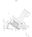
- FIG. 7 describes electrical connection between light emitting elements and a circuit unit.
- FIG. 8 is a bottom view showing the lighting fixture relating to the embodiment of the present invention.
- FIG. 9 describes effects of the lighting fixture relating to the embodiment of the present invention.
- FIG. 10 is a bottom view showing a lighting fixture relating to a modification of the embodiment of the present invention.
- FIG. 11 is a bottom view showing a lighting fixture relating to another modification of the embodiment of the present invention.
- the lighting fixture 1 includes a light emitting module 10 , a frame 20 , a housing 30 , a bearing 40 , and a hold-down member 50 .
- the frame 20 includes a main frame body 21 which is substantially cylindrical, a flange 22 which is substantially annular, a bearing placement part 23 which is substantially annular, and three attachment springs 24 . While the flange 22 extends outward from one of openings of the main frame body 21 , the bearing placement part 23 extends inward from the other opening of the main frame body 21 .
- the frame 20 is for example a metal member.
- the frame 20 is fixed to a ceiling 2 .
- the frame main body 21 , the bearing mounting part 23 , and the attachment springs 24 in an elastically deformed state are embedded into an embedding hole 2 a of the ceiling 2 , and then the frame main body 21 and the bearing mounting part 23 are fixed to the ceiling 2 by the attachment springs 24 in an elastically restored state while the flange 22 is in abutment with a ceiling surface 2 b.
- the housing 30 is a metal member including a module housing part 31 and a heat sink 32 which are integrally formed.
- the module housing part 31 is cylindrical and bottomed, and houses therein the light emitting module 10 , a reflecting mirror 34 , and a diffuser 35 .
- the heat sink 32 extends from a bottom of the module housing part 31 , and has a plurality of radiating fins 32 a.
- the housing 30 is rotatable relative to the frame 20 in respective directions indicated by arrows A 1 and A 2 about a rotational axis J 1 which is parallel to the Y-axis. Also, the housing 30 is swingable in respective directions indicated by arrows A 3 and A 4 about a swing axis J 2 which is parallel to the Z-axis. That is, the lighting fixture 1 is a so-called universal downlight, and a user can freely change the illumination direction of the lighting fixture 1 which is placed on the ceiling 2 .
- FIG. 3 describes that the housing 30 , which houses therein the light emitting module 10 , is attached to the frame 20 so as to be rotatable relative to the frame 20 .
- the bearing 40 is fit onto the housing 30 so as to be provided near the boundary between the module housing part 31 and the heat sink 32 .
- the housing 30 is attached to the frame 20 via the bearing 40 .
- the bearing 40 is held down to the bearing mounting part 23 by the hold-down member 50 .
- the housing 30 is fixed to the frame 20 .
- the hold-down member 50 is fixed only to the bearing mounting part 23 .
- a gap between the hold-down member 50 and the bearing mounting part 23 is slightly greater than the thickness of the bearing 40 . Accordingly, the bearing 40 is rotatable about the rotational axis J 1 while being prevented from moving upward and downward.
- the housing 30 which is fixed to the bearing 40 , is rotatable 360 degrees relative to the frame 20 about the rotational axis J 1 , integrally with the bearing 40 .
- FIG. 4 describes that the housing 30 , which houses therein the light emitting module 10 , is attached to the frame 20 so as to be swingable relative to the frame 20 .
- the housing 30 is supported by the bearing 40 so as to be swingable about a pair of bolts 60 functioning as the swing axis J 2 .
- the bearing 40 includes a main part 41 which is annular plate-like and a pair of attachment pieces 42 which are provided on an outer edge of the main part 41 so as to face each other.
- the attachment pieces 42 each have an insertion hole 42 a into which a corresponding one of the pair of bolts 60 functioning as the swing axis J 2 is to be inserted.
- the housing 30 has two screw holes 33 on a surface thereof onto which the bearing 40 is fit.
- the screw holes 33 correspond in position to the respective insertion holes 42 a of the bearing 40 .
- the housing 30 is fixed to the bearing 40 by the bolts 60 , by screwing the bolts 60 which have been inserted into the respective insertion holes 42 a coupled to the respective screw holes 33 , further into the respective screw holes 33 .
- the housing 30 is supported so as to be swingable relative to the bearing 40 about the pair of bolts 60 functioning as the swing axis J 2 .
- the swing axis J 2 is eccentric to the center of the bearing 40 .
- the lighting fixture 1 which is assembled and embedded in the ceiling 2 as described above, is usable while the housing 30 is inclined relative to the frame 20 as shown in FIG. 5 .
- the light emitting module 10 is attached to a bottom surface 31 a of the module housing part 31 .
- the reflecting mirror 34 is substantially cylindrical, and has a diameter which increases as the distance from the light emitting module 10 increases.
- the reflecting mirror 34 has a light reflecting surface inside thereof.
- the reflecting mirror 34 is housed in the module mounting part 31 so as to surround the light emitting module 10 .
- the diffuser 35 is placed so as to close an opening of the reflecting mirror 34 opposite to the light emitting module 10 . With this structure, light emitted from the light emitting module 10 is reflected by the reflecting mirror 34 and diffused by the diffuser 35 .
- an angle of inclination of the bottom surface 31 a relative to the ceiling 2 varies.
- an angle of inclination of the light emitting module 10 relative to the ceiling 2 also varies. This also results in variation of an angle of light emission with respect to light, which is emitted from the light emitting module 10 , reflected by the reflecting mirror 34 , and diffused by the diffuser 35 .
- the light emitting module 10 is electrically connected with a circuit unit.
- the light emitting module 10 receives an electrical power supplied from the circuit unit thereby to emit light.
- the circuit unit is described later in detail.
- Section (a) of FIG. 6 is a plane view showing the light emitting module 10 .
- Section (b) of FIG. 6 is a cross-sectional view showing the light emitting module 10 , taken along a line A-A′ in section (a) of FIG. 6 .
- the light emitting module 10 includes a substrate 11 , first light emitting parts 12 a 1 to 12 a 4 , second light emitting parts 12 b 1 to 12 b 4 , and terminals 15 a , 15 b , 16 a , and 16 b.
- the substrate 11 is a rectangular plate, and has a double-layered structure of an insulating layer such as a ceramic substrate and a heat conductive resin and a metal layer such as an aluminum substrate, for example.
- the first light emitting parts 12 a , to 12 a 4 are each composed of a plurality of light emitting elements 13 and a first phosphor layer 14 a
- the second light emitting parts 12 b 1 to 12 b 4 are each composed of a plurality of light emitting elements 13 and a second phosphor layer 14 b.
- the light emitting elements 13 are each for example a GaN blue LED which emits blue light having a peak wavelength of 430 nm to 470 nm.
- a plurality of element arrays arranged in the Z-axis direction are mounted on the substrate 11 .
- the element arrays are each composed of a plurality of light emitting elements 13 which are linearly arranged in the X-axis direction.
- the light emitting elements 13 are face-up mounted on an upper surface 11 a of the substrate 11 with use of the COB (Chip on Board) technique.
- the number of light emitting elements 13 included in each element array decreases from the center outward on the substrate 11 in the Z-axis direction. Accordingly, the light emitting module 10 has a light emitting surface 12 whose entire shape is substantially a circle.
- An element array is sealed by one of a first phosphor layer 14 a and a second phosphor layer 14 b which are elongated, thereby to constitute a light emitting part.
- Element arrays which are each sealed by the first phosphor layer 14 a are the first light emitting parts 12 a 1 to 12 a 4 .
- Element arrays which are each sealed by the second phosphor layer 14 b are the second light emitting parts 12 b 1 to 12 b 4 .
- the shape of the first light emitting parts 12 a 1 to 12 a 4 and the shape of the second light emitting parts 12 b 1 to 12 b 4 depend on the shape of the first phosphor layer 14 a and the shape of the second phosphor layer 14 b , respectively.
- the first light emitting parts 12 a 1 to 12 a 4 and the second light emitting parts 12 b 1 to 12 b 4 are each elongated and each have a longitudinal direction in the X-axis direction.
- the element arrays are separately sealed in this way. This provides a space between each two adjacent of the sealing members, thereby to improve the heat sink effect.
- the first phosphor layer 14 a is formed by dispersing a wavelength conversion material in a transparent resin material.
- the transparent resin material may be mixed with a dispersing material in addition to the transparent resin material.
- the transparent resin material may be a silicone resin, a fluoro resin, a silicone epoxy hybrid resin, a urea resin, or the like.
- the wavelength conversion material may be a yellow phosphor, a combination of a green phosphor and a red phosphor, or the like.
- the wavelength conversion material may be one of a phosphor having a garnet structure which is known as a YAG phosphor, an oxynitride phosphor having a sialon structure, other oxynitride phosphor, a sulfide phosphor, a silicate phosphor, and the like, or a mixture of at least two types of these phosphors.
- Light emitted from the light emitting element 13 is wavelength-converted by the yellow phosphor, the green phosphor, and the red phosphor into yellow light, green light, and red light, respectively.
- the first light emitting parts 12 a 1 to 12 a 4 each output white light having a correlated color temperature in the vicinity of 2200 K.
- the white light results from mixing of blue light emitted from the light emitting elements 13 and at least one of yellow light, green light, and red light which are generated due to wavelength-conversion of part of the blue light by the first phosphor layer 14 a.
- the second phosphor layer 14 b has the same structure as the first phosphor layer 14 a .
- the second phosphor layer 14 b differs from the first phosphor layer 14 a in terms of amount, type, rate, and so on of a phosphor to be added as a wavelength conversion material.
- the second light emitting parts 12 b 1 to 12 b 4 each output white light having a correlated color temperature in the vicinity of 8000 K.
- the white light results from mixing of blue light emitted from the light emitting elements 13 and at least one of yellow light, green light, and red light which are generated due to wavelength-conversion of part of the blue light by the second phosphor layer 14 b.
- FIG. 8 is a bottom view showing the lighting fixture 1 from which the reflecting mirror 34 and the diffuser 35 are removed to expose the light emitting module 10 .
- a plurality of light emitting parts which output white light having two different color temperatures are alternately arranged in parallel to the swing axis J 2 .
- the first light emitting parts and the second light emitting parts are alternatively arranged in parallel to the swing axis J 2 .
- the first light emitting part 12 a 1 , the second light emitting part 12 b 1 , the first light emitting part 12 a 2 , the second light emitting part 12 b 2 , the first light emitting part 12 a 3 , the second light emitting part 12 b 3 , the first light emitting part 12 a 4 , and the second light emitting part 12 b 4 are arranged in parallel to the swing axis J 2 in the stated order.
- the first light emitting parts 12 a 1 to 12 a 4 and the second light emitting parts 12 b 1 to 12 b 4 are arranged each so as to have a longitudinal direction J 3 which is substantially perpendicular to the swing axis J 2 .
- the light emitting parts are arranged eccentrically to the swing axis J 2 as shown in FIG. 8 .
- the light emitting parts are arranged, such that a virtual line L connecting the respective centers of the light emitting parts in the longitudinal direction J 3 is parallel to the swing axis J 2 and is offset from the swing axis J 2 by a distance 1 .
- the lighting fixture 1 is used while the housing 30 swings such that the virtual line L is lower than the swing axis J 2 in the vertical direction. This reduces an amount of light shielded by the frame 20 . Therefore, the lighting fixture 1 can illuminate a large range of a wall at a high luminance.
- the terminals 15 a , 15 b , 16 a , and 16 b are formed on the upper surface 11 a of the substrate 11 with a conductor pattern.
- the terminals 15 a and 16 a supply an electrical power to the light emitting elements 13 included in the first light emitting parts 12 a 1 to 12 a 4 .
- the terminals 15 b and 16 b supply an electrical power to the light emitting elements 13 included in the second light emitting parts 12 b 1 to 12 b 4 .
- the terminals 15 a and 15 b are electrode terminals, and the terminals 16 a and 16 b are ground terminals.
- wirings 17 and 18 are formed on the upper surface 11 a of the substrate 11 with a conductor pattern. Each two adjacent of the light emitting elements 13 included in the first light emitting parts 12 a 1 to 12 a 4 are electrically connected with each other via the wiring 17 . Each two adjacent of the light emitting elements 13 included in the second light emitting parts 12 b 1 to 12 b 4 are electrically connected with each other via the wiring 18 .
- the first light emitting parts 12 a 1 to 12 a 4 differ from each other in terms of the number of the light emitting elements 13 included therein.
- the second light emitting parts 12 b 1 to 12 b 4 differ from each other in terms of the number of the light emitting elements 13 included therein.
- the light emitting elements 13 included in the first light emitting part 12 a 1 are series-connected with the light emitting elements 13 included in the first light emitting part 12 a 3 via the wiring 17 .
- the light emitting elements 13 included in the first light emitting part 12 a are series-connected with the light emitting elements 13 included in the first light emitting part 12 a 4 via the wiring 17 . This results in generation of two groups each including 36 light emitting elements 13 which are series-connected. These two groups are parallel-connected thereby to equalize a supply amount of electric power to the light emitting elements 13 .
- the light emitting elements 13 included in the second light emitting part 12 b 1 are series-connected with the light emitting elements 13 included in the second light emitting part 12 b 3 via the wiring 18 .
- the light emitting elements 13 included in the second light emitting part 12 b 1 are series-connected with the light emitting elements 13 included in the second light emitting part 12 b 4 via the wiring 18 . This results in generation of two groups each including 28 light emitting elements 13 which are series-connected. These two groups are parallel-connected thereby to equalize a supply amount of electric power to the light emitting elements 13 .
- the first light emitting parts are larger than the second light emitting parts in terms of the number of light emitting elements 13 to be included. This is because the first light emitting parts, which have a low color temperature, are lower than the second light emitting parts, which have a high color temperature, in terms of light emitting efficiency (lm/W).
- the terminals 15 a , 15 b , 16 a , and 16 b are connected with a lighting circuit 4 c of a circuit unit 4 which is provided outside of the housing 30 via respective lead wirings 71 .
- the lighting fixture 1 can supply an electrical current to each of the first light emitting parts 12 a 1 to 12 a 4 and the second light emitting parts 12 b 1 to 12 b 4 via separate systems.
- the circuit unit 4 is a unitized lighting circuit which includes the lighting circuit 4 c , an instruction detection circuit 4 d and a control circuit 4 e.
- the circuit unit 4 is electrically connected with an external commercial AC source which is not illustrated.
- the circuit unit 4 supplies an electrical current which is input from the commercial AC source to the light emitting module 10 .
- the circuit unit 4 separately controls lighting of the first light emitting parts 12 a 1 to 12 a 4 and the second light emitting parts 12 b 1 to 12 b 4 .
- the circuit unit 4 is connected with a dimming-toning unit 5 .
- the dimming-toning unit 5 for example includes buttons, tabs, and the like.
- the dimming-toning unit 5 is used by a user to adjust the luminance and the color temperature of illumination light of the lighting fixture 1 .
- the user operates the buttons, the tabs, and the like of the dimming-toning unit 5 so as to designate desired brightness (luminance) and hue (color temperature) of illumination light.
- the dimming-toning unit 5 Upon receiving the user's operation, the dimming-toning unit 5 outputs a dimming-toning signal corresponding to the user's operation to the circuit unit 4 .
- the structure of the dimming-toning unit 5 is not limited to this.
- the dimming-toning unit 5 may generate a dimming-toning signal by a computer program which is incorporated therein in advance, and output the generated dimming-t
- the lighting circuit unit 4 c is a circuit including an AC/DC converter which is not illustrated, and separately supplies an electric power to the first light emitting parts 12 a 1 to 12 a 4 and the second light emitting parts 12 b 1 to 12 b 4 .
- the lighting circuit unit 4 c controls the AC/DC converter to convert an AC voltage supplied from the commercial AC source to two types of DC voltages which are each appropriate to the first light emitting parts 12 a 1 to 12 a 4 and the second light emitting parts 12 b 1 to 12 b 4 , and to apply the appropriate DC voltage to each of the light emitting elements 13 included in the first light emitting parts 12 a 1 to 12 a 4 and the second light emitting parts 12 b 1 to 12 b 4 as a forward voltage.
- the AC/DC converter is for example a diode bridge converter.
- the instruction detection circuit 4 d acquires the dimming-toning signal output from the dimming-toning unit 5 .
- the dimming-toning signal includes information indicating a dimming ratio and a color temperature which correspond to the user's operation.
- the dimming ratio indicates a brightness relative to a brightness of illumination light at full lighting (at lighting with light output at 100%).
- the color temperature is represented by a numerical value of 2200 K to 6700 K.
- the instruction detection circuit 4 d Upon receiving the dimming-toning signal from the dimming-toning unit 5 , the instruction detection circuit 4 d extracts the information indicating the dimming ratio and the color temperature from the dimming-toning signal, and outputs the extracted information to the control circuit 4 e.
- the control circuit 4 e includes a microprocessor and a memory.
- the control circuit 4 e controls light emission of the first light emitting parts 12 a 1 to 12 a 4 and the second light emitting parts 12 b 1 to 12 b 4 by the microprocessor in order to realize the dimming ratio and the color temperature input from the instruction detection circuit 4 d.
- the memory for example stores therein a lookup table in which an amount of current to be supplied to each of the first light emitting parts 12 a 1 to 12 a 4 and the second light emitting parts 12 b 1 to 12 b 4 for desired dimming ratio and color temperature.
- the microprocessor determines the amount of current to be supplied to each of the first light emitting parts 12 a 1 to 12 a 4 and the second light emitting parts 12 b 1 to 12 b 4 , with use of the lookup table.
- the control circuit 4 e sets a duty ratio for each of the first light emitting parts 12 a 1 to 12 a 4 and the second light emitting parts 12 b 1 to 12 b 4 to perform PWM (Pulse Width Modulation) control on each of the light emitting parts, such that the determined amount of current is supplied to each of the light emitting parts.
- PWM Pulse Width Modulation
- the lighting fixture 1 can output illumination light having a user's desired color temperature which ranges from candle light having a color temperature of approximately 2200 K to day light having a color temperature of approximately 6700 K.
- the lighting fixture 1 is placed on the ceiling 2 .
- the lighting fixture 1 swings a certain degree about the swing axis, and illuminates the wall 3 in a fixed state.
- the distance between the lighting fixture 1 and a range of the wall 3 which is an illuminated surface decreases as the range is closer to the ceiling 2 , and increases as the range is farther from the ceiling 2 .
- light emitted from the light emitting elements 13 toward a range of the wall 3 which is near the ceiling 2 is difficult to be diffused.
- the emitted light is easier to be diffused.
- Section (b) of FIG. 9 shows that light emitting parts of two colors are alternately arranged in a direction perpendicular to the swing axis J 2 .
- Section (c) of FIG. 9 is a pattern diagram describing appearance of illumination light in the case shown in section (b) of FIG. 9 . While a range of the wall 3 where light of two colors is not sufficiently diffused (range of the wall 3 which is near the ceiling 2 ) is illuminated with only light emitted from the light emitting parts of one of the two colors, other remaining range of the wall 3 is illuminated with light which is a mixture of light emitted from the light emitting parts of the two colors.
- section (d) of FIG. 9 shows light emitting parts of two colors are alternately arranged in parallel to the swing axis J 2 , which correspond to the light emitting module 10 of the present embodiment.
- Section (e) of FIG. 9 is a pattern diagram describing appearance of illumination light in the case shown in section (d) of FIG. 9 . While a range of the wall 3 where light of two colors is not sufficiently diffused (range of the wall 3 which is near the ceiling 2 ) is illuminated with light emitted from the light emitting parts of the two colors alternately at short intervals of distance, other remaining range of the wall 3 is illuminated with light which is a mixture of light emitted from the light emitting parts of the two colors.
- the first light emitting parts 12 a 1 to 12 a 4 and the second light emitting parts 12 b 1 to 12 b 4 should be alternately arranged in parallel to the swing axis J 2 as described in the present embodiment. This reduces an uncomfortable feeling a user has in an illumination space where a range of a wall which is near a ceiling is illuminated.
- the exemplified lighting fixture may be modified as follows.
- the present invention is not of course limited to the lighting fixture described in the above embodiment.
- the first light emitting parts 12 a 1 to 12 a 4 and the second light emitting parts 12 b 1 to 12 b 4 each have a longitudinal direction J 3 which is substantially perpendicular to the swing axis J 2 .
- the longitudinal direction of the light emitting parts does not necessarily need to be substantially perpendicular to the swing axis J 2 .
- the longitudinal direction of the light emitting parts should be desirably perpendicular to the swing axis J 2 at an angle greater than 45 degrees.
- All the light emitting elements each do not necessarily need to have a longitudinal direction J 3 which is substantially perpendicular to the swing axis J 2 .
- the light emitting surface 12 may have entirely a fan shape, such that only one or more light emitting parts located near the center on the light emitting surface 12 each have a longitudinal direction which is substantially perpendicular to the swing axis J 2 , and the longer the distance between each of other remaining light emitting parts and the center on the light emitting surface 12 is, the more inclined each of the other remaining light emitting part becomes.
- the light emitting surface may have a fan shape so as to have a large region across the swing axis J 2 where more light emitting parts are located and a small region across the swing axis J 2 where less light emitting parts are located.
- All the light emitting elements each do not necessarily need to have a longitudinal direction J 3 which is substantially perpendicular to the swing axis J 2 .
- One or more light emitting parts each may have a longitudinal direction which is parallel to the swing axis J 2 as long as light emitting parts whose longitudinal direction is substantially perpendicular to the swing axis J 2 account for 50% or more of the entire light emitting surface in terms of area. Accordingly, the present invention includes the case where light emitting parts of different colors are arranged in a circular pattern and the case where light emitting parts of different colors are arranged in a staggered pattern.
- the element array and the phosphor layer constituting each of the light emitting elements each have a longitudinal direction which is substantially perpendicular to the swing axis J 2 .
- this structure is not essential to the present invention.
- the light emitting part has the shape depending on the shape of the phosphor layer. Accordingly, at least the phosphor layer only needs to have a longitudinal direction which is substantially perpendicular to the swing axis J 2 , and the element array included in each of the light emitting parts does not need to be linear.
- the element array included in the light emitting part may have a zigzag shape. Further alternatively, the number of element arrays to be included in each of the light emitting parts may be two.
- the first light emitting parts and the second light emitting parts which emit white light of two different colors, are alternately arranged on the substrate.
- the lighting fixture relating to the present invention is not limited to this structure.
- two first light emitting parts and one second light emitting part are repeatedly arranged in this order on the substrate, for example.
- the number of the first light emitting parts and the number of the second light emitting parts which are to be repeatedly arranged may be of course reversible.
- the first light emitting parts and the second light emitting parts are alternately arranged on the substrate.
- a light emitting module 110 shown in FIG. 10 may be employed in which the first light emitting parts 12 a 1 to 12 a 4 are arranged in the left half of the substrate, and the second light emitting parts 12 b 1 to 12 b 4 are arranged in the right half of the substrate.
- the light emitting module 10 of the above embodiment has the light emitting surface 12 which is circular.
- the light emitting module 110 shown in FIG. 10 has a light emitting surface which is rectangular.
- the present invention includes the structure of the light emitting module having a rectangular light emitting surface.
- first light emitting parts and the second light emitting parts are each elongated.
- first light emitting parts and the second light emitting parts each may be for example an SMD (Surface Mount Device).
- two types of SMDs which emit white light having different color temperatures may be arranged in matrix.
- arrays of SMDs which emit white light having a low color temperature and arrays of SMDs which emit white light having a high color temperature may be alternately arranged in parallel to the swing axis.
- the present invention includes the structure in which two different types of SMDs are arranged in the direction of the swing axis, as shown in FIG. 11 .
- a light emitting module 210 shown in FIG. 11 has the structure in which SMDs 211 and 212 are arranged in parallel to the swing axis J 2 .
- the SMD 211 is composed of an LED 211 a and a sealing member 211 b
- the SMD 212 is composed of an LED 212 a and a sealing member 212 b .
- the SMDs 211 and 212 each emit white light having a different color temperature.
- the light emitting elements relating to the present invention are not limited to blue LEDs which emit blue light having a peak wavelength of 430 nm to 470 nm.
- the light emitting elements relating to the present invention may be blue LEDs which emit blue light having other peak wavelength, or LEDs which emit light having a peak wavelength of 420 nm or less which ranges from ultraviolet light to blue-violet light.
- a phosphor as a wavelength conversion material may be a blue phosphor, a green phosphor, a red phosphor, or a mixture of the blue, green, and red phosphors.
- the first light emitting parts and the second light emitting parts each generate white light through a combination of blue LEDs and a phosphor layer functioning as a wavelength conversion member.
- the first light emitting parts and the second light emitting parts relating to the present invention each do not necessarily need to be composed of light emitting elements and a phosphor layer.
- the first light emitting part may be composed of blue LEDs and a phosphor layer
- the second light emitting part may be composed of red light emitting elements and a translucent material which does not include a phosphor, for example.
- toning is performed through a combination of the light emitting parts, which emit white light having a low color temperature, and the light emitting parts, which emit white light having a high color temperature.
- the lighting fixture 1 outputs white light which ranges from candle light to day light having a different hue.
- white light having different color temperatures is toned.
- the lighting fixture relating to the present invention may include three or more light emitting parts each which emit light of a different color.
- the present invention includes the case where a lighting fixture which outputs white light by mixing light of three colors which is emitted from a red light emitting element (R) as a first light emitting part, a green light emitting element (G) as a second light emitting part, and a blue light emitting element (B) as a third light emitting part.
- a lighting fixture which outputs white light by mixing light of three colors which is emitted from a red light emitting element (R) as a first light emitting part, a green light emitting element (G) as a second light emitting part, and a blue light emitting element (B) as a third light emitting part.
- the first light emitting parts 12 a 1 to 12 a 4 and the second light emitting parts 12 b 1 to 12 b 4 are modularized on the same substrate.
- the lighting fixture relating to the present invention is not limited to this structure. It is not necessary to the present invention that the first light emitting parts 12 a 1 to 12 a 4 and the second light emitting parts 12 b 1 to 12 b 4 are all arranged on the same substrate, as long as the first light emitting parts 12 a 1 to 12 a 4 and the second light emitting parts 12 b 1 to 12 b 4 are attached to the housing 30 .
- the light emitting elements relating to the present invention may be LDs (laser diodes), EL (electroluminescence) elements, or the like.
- a lighting fixture comprises: a frame; a housing that is supported so as to be swingable relative to the frame about a swing axis; a first light emitting part that is provided in the housing and emits light of a first color; and a second light emitting part that is provided in the housing and emits light of a second color differing from the first color, wherein the first light emitting part and the second light emitting part are arranged in parallel to the swing axis.
- first light emitting part and the second light emitting part are provided in the housing so as to illuminate in the same direction.
- the first light emitting part and the second light emitting part are each elongated, and each have a longitudinal direction that is perpendicular to the swing axis.
- the lighting fixture can illuminate a large range of the wall at a high luminance.
- the first light emitting part and the second light emitting part are formed on the same substrate, and the first light emitting part and the second light emitting part are modularized and attached to the housing.
- the first light emitting part and the second housing part which are formed on the same substrate, illuminate in the same direction. Also, it is possible to manufacture various types of lighting fixtures which vary in terms of shape, size, dimming range, and so on by attaching various types of modules to the housing.
- the first light emitting part and the second light emitting part are each provided in plural, and the first light emitting parts and the second light emitting parts are alternately arranged on the substrate.
- the first light emitting parts each include a plurality of light emitting elements that are linearly arranged on the substrate and a first sealing member that collectively seals the light emitting elements
- the second light emitting parts each include a plurality of light emitting elements that are linearly arranged on the substrate and a second sealing member that collectively seals the light emitting elements.
- the expression “a plurality of light emitting elements are linearly arranged” is not limited to the case where a plurality of light emitting elements are arranged in a single line, and includes the case where two arrays each including a plurality of light emitting elements are arranged and the case where a plurality of light emitting elements are arranged in a zigzag pattern.
- the light emitting elements which are included in each of the first light emitting parts and the second housing parts, are separately sealed for each array. This provides a space between each two adjacent of the sealing members, thereby to improve the heat sink effect.
- the light of the first color and the light of the second color are each white light having a different color temperature
- the lighting fixture is connected with a toning unit that designates a color temperature of illumination light
- the lighting fixture further comprises a circuit unit that supplies a driving current separately to the first light emitting part and the second light emitting part such that illumination light having the color temperature designated by the toning unit is output.
Abstract
Description
- 1 lighting fixture
- 10, 110, and 210 light emitting module
- 12 a 1 to 12 a 4 first light emitting part
- 12 b 1 to 12 b 4 second light emitting part
- 13 light emitting element
- 14 a first phosphor layer
- 14 b second phosphor layer
- 20 frame
- 30 housing
- 40 bearing
- 50 hold-down member
- 60 bolt (swing axis)
Claims (6)
Applications Claiming Priority (2)
| Application Number | Priority Date | Filing Date | Title |
|---|---|---|---|
| JP2012288047A JP6074704B2 (en) | 2012-12-28 | 2012-12-28 | lighting equipment |
| JP2012-288047 | 2012-12-28 |
Publications (2)
| Publication Number | Publication Date |
|---|---|
| US20140185283A1 US20140185283A1 (en) | 2014-07-03 |
| US9200766B2 true US9200766B2 (en) | 2015-12-01 |
Family
ID=49958201
Family Applications (1)
| Application Number | Title | Priority Date | Filing Date |
|---|---|---|---|
| US14/141,666 Active 2034-02-13 US9200766B2 (en) | 2012-12-28 | 2013-12-27 | Lighting fixture |
Country Status (4)
| Country | Link |
|---|---|
| US (1) | US9200766B2 (en) |
| EP (1) | EP2749809B1 (en) |
| JP (1) | JP6074704B2 (en) |
| CN (1) | CN103912830B (en) |
Families Citing this family (3)
| Publication number | Priority date | Publication date | Assignee | Title |
|---|---|---|---|---|
| GB2539167A (en) * | 2015-03-13 | 2016-12-14 | Ac/Dc Led Ltd | Luminaires |
| JP6558785B1 (en) | 2018-04-16 | 2019-08-14 | 未彩 河野 | Lighting device |
| US11525557B2 (en) * | 2019-04-11 | 2022-12-13 | Xiamen Eco Lighting Co. Ltd. | Downlight apparatus |
Citations (13)
| Publication number | Priority date | Publication date | Assignee | Title |
|---|---|---|---|---|
| US5548499A (en) * | 1994-08-19 | 1996-08-20 | Amp Plus, Inc. | Light fixture for recess in sloped ceiling |
| US6211626B1 (en) * | 1997-08-26 | 2001-04-03 | Color Kinetics, Incorporated | Illumination components |
| US20030123252A1 (en) * | 1999-09-17 | 2003-07-03 | Cercone Samuel P. | Adjustable fluorescent lighting fixtures |
| US20050111224A1 (en) * | 2003-11-26 | 2005-05-26 | Ming-Kuei Lin | Swing lamp adapted to show flickering light and shade |
| US20060262521A1 (en) | 2005-05-23 | 2006-11-23 | Color Kinetics Incorporated | Methods and apparatus for providing lighting via a grid system of a suspended ceiling |
| TW200905128A (en) | 2007-02-13 | 2009-02-01 | Showa Denko Kk | Lighting system |
| WO2009055334A1 (en) | 2007-10-24 | 2009-04-30 | Lsi Industries, Inc. | Adjustable lighting apparatus |
| US20100103663A1 (en) | 2008-03-11 | 2010-04-29 | Robe Lighting S.R.O. | Led array beam control luminaires |
| EP2365525A2 (en) | 2010-03-12 | 2011-09-14 | Toshiba Lighting & Technology Corporation | Illumination apparatus having an array of red and phosphour coated blue LEDs |
| CN102192424A (en) | 2010-03-12 | 2011-09-21 | 东芝照明技术株式会社 | Light emitting device and illumination apparatus |
| US20110278605A1 (en) | 2010-05-17 | 2011-11-17 | Sharp Kabushiki Kaisha | Light emitting device and illumination device |
| US20110285292A1 (en) | 2007-12-22 | 2011-11-24 | Philips Solid-State Lighting Solutions, Inc. | Led-based luminaires for large-scale architectural illumination |
| WO2012026420A1 (en) | 2010-08-25 | 2012-03-01 | パナソニック株式会社 | Illumination apparatus |
Family Cites Families (5)
| Publication number | Priority date | Publication date | Assignee | Title |
|---|---|---|---|---|
| JP2008078015A (en) * | 2006-09-22 | 2008-04-03 | Toshiba Lighting & Technology Corp | Luminaire |
| JP5722519B2 (en) * | 2008-02-29 | 2015-05-20 | Idec株式会社 | LED ceiling lighting device |
| EP2546899B1 (en) * | 2010-03-11 | 2015-06-24 | Panasonic Intellectual Property Management Co., Ltd. | Light emitting module, light source device, liquid crystal display device |
| BR112012027037B1 (en) * | 2010-04-23 | 2020-05-26 | Harman Professional Denmark Aps | LIGHTING DEVICE |
| CN201934954U (en) * | 2010-11-19 | 2011-08-17 | 林万炯 | Angle-adjustable high-power LED spotlight |
-
2012
- 2012-12-28 JP JP2012288047A patent/JP6074704B2/en active Active
-
2013
- 2013-12-26 CN CN201310733675.2A patent/CN103912830B/en active Active
- 2013-12-27 EP EP13199666.2A patent/EP2749809B1/en active Active
- 2013-12-27 US US14/141,666 patent/US9200766B2/en active Active
Patent Citations (20)
| Publication number | Priority date | Publication date | Assignee | Title |
|---|---|---|---|---|
| US5548499A (en) * | 1994-08-19 | 1996-08-20 | Amp Plus, Inc. | Light fixture for recess in sloped ceiling |
| US6211626B1 (en) * | 1997-08-26 | 2001-04-03 | Color Kinetics, Incorporated | Illumination components |
| US20030123252A1 (en) * | 1999-09-17 | 2003-07-03 | Cercone Samuel P. | Adjustable fluorescent lighting fixtures |
| US20050111224A1 (en) * | 2003-11-26 | 2005-05-26 | Ming-Kuei Lin | Swing lamp adapted to show flickering light and shade |
| US20060262521A1 (en) | 2005-05-23 | 2006-11-23 | Color Kinetics Incorporated | Methods and apparatus for providing lighting via a grid system of a suspended ceiling |
| US20120044670A1 (en) | 2005-05-23 | 2012-02-23 | Koninklijke Philips Electronics N.V. | Methods and apparatus for providing lighting via a grid system of a suspended ceiling |
| TW200905128A (en) | 2007-02-13 | 2009-02-01 | Showa Denko Kk | Lighting system |
| US20090290340A1 (en) | 2007-02-13 | 2009-11-26 | Showa Denko K.K. | Lighting Device |
| WO2009055334A1 (en) | 2007-10-24 | 2009-04-30 | Lsi Industries, Inc. | Adjustable lighting apparatus |
| US20090109670A1 (en) | 2007-10-24 | 2009-04-30 | Lsi Industries, Inc. | Adjustable lighting apparatus |
| US20110285292A1 (en) | 2007-12-22 | 2011-11-24 | Philips Solid-State Lighting Solutions, Inc. | Led-based luminaires for large-scale architectural illumination |
| US20100103663A1 (en) | 2008-03-11 | 2010-04-29 | Robe Lighting S.R.O. | Led array beam control luminaires |
| WO2010048221A2 (en) | 2008-10-20 | 2010-04-29 | Robe Lighting, Inc. | Led array beam control luminaires |
| CN102216673A (en) | 2008-10-20 | 2011-10-12 | 罗布照明有限公司 | Kubis frantisek [cz]; jurik pavel |
| CN102192424A (en) | 2010-03-12 | 2011-09-21 | 东芝照明技术株式会社 | Light emitting device and illumination apparatus |
| US20110222264A1 (en) | 2010-03-12 | 2011-09-15 | Toshiba Lighting & Technology Corporation | Light emitting device and illumination apparatus |
| EP2365525A2 (en) | 2010-03-12 | 2011-09-14 | Toshiba Lighting & Technology Corporation | Illumination apparatus having an array of red and phosphour coated blue LEDs |
| US20110278605A1 (en) | 2010-05-17 | 2011-11-17 | Sharp Kabushiki Kaisha | Light emitting device and illumination device |
| JP2012004519A (en) | 2010-05-17 | 2012-01-05 | Sharp Corp | Light emitting device and illumination device |
| WO2012026420A1 (en) | 2010-08-25 | 2012-03-01 | パナソニック株式会社 | Illumination apparatus |
Non-Patent Citations (2)
| Title |
|---|
| Extended European Search Report in 13199666.2, dated Mar. 25, 2014. |
| Office Action issued in China Counterpart Patent Appl. No. 201310733675.2, dated Aug. 21, 2015 , along with an English translation thereof. |
Also Published As
| Publication number | Publication date |
|---|---|
| US20140185283A1 (en) | 2014-07-03 |
| CN103912830B (en) | 2016-08-17 |
| EP2749809B1 (en) | 2016-03-09 |
| EP2749809A1 (en) | 2014-07-02 |
| CN103912830A (en) | 2014-07-09 |
| JP6074704B2 (en) | 2017-02-08 |
| JP2014130746A (en) | 2014-07-10 |
Similar Documents
| Publication | Publication Date | Title |
|---|---|---|
| JP5325208B2 (en) | Lighting device and lighting method | |
| JP6369784B2 (en) | LIGHT EMITTING DEVICE AND LIGHTING LIGHT SOURCE AND LIGHTING DEVICE USING THE SAME | |
| US9312302B2 (en) | Light emitting module, lighting apparatus, and lighting fixture | |
| US7918581B2 (en) | Lighting device and lighting method | |
| US9417478B2 (en) | Lighting device and lighting method | |
| JP5476128B2 (en) | Illumination device, illumination method, optical filter, and light filtering method | |
| US20160208989A1 (en) | Lighting device and lighting method | |
| US20110310602A1 (en) | Lighting device and lighting method | |
| US9416924B2 (en) | Light emission module | |
| JP2010527157A (en) | Lighting device and lighting method | |
| JP2010527156A (en) | Lighting device and lighting method | |
| JP2010527155A (en) | Lighting device and lighting method | |
| JP2010527510A (en) | Lighting device and lighting method | |
| US20140301074A1 (en) | Led lighting system, method, and apparatus | |
| KR20140116536A (en) | Lighting device and method of lighting | |
| US8841834B2 (en) | Solid state lighting systems using OLEDs | |
| US9013097B2 (en) | Light-emitting module, lighting device, and lighting fixture | |
| US20100254127A1 (en) | LED-based lighting module for emitting white light with easily adjustable color temperature | |
| US9200766B2 (en) | Lighting fixture | |
| TW201312041A (en) | Light-emitting circuit and luminaire | |
| KR20140067931A (en) | Illumination device with combination of discrete light emitting diode and organic light emitting diode components | |
| TW201812207A (en) | Illumination device | |
| JP2014194858A (en) | Led lighting device | |
| JP2015018693A (en) | Lighting fixture, illuminating device and light-emitting module | |
| JP7186597B2 (en) | LED module and lighting device |
Legal Events
| Date | Code | Title | Description |
|---|---|---|---|
| AS | Assignment |
Owner name: PANASONIC CORPORATION, JAPAN Free format text: ASSIGNMENT OF ASSIGNORS INTEREST;ASSIGNORS:ISHIMORI, ATSUYOSHI;OGATA, TOSHIFUMI;HYODO, WAKABA;SIGNING DATES FROM 20131219 TO 20140103;REEL/FRAME:032732/0215 |
|
| AS | Assignment |
Owner name: PANASONIC INTELLECTUAL PROPERTY MANAGEMENT CO., LTD., JAPAN Free format text: ASSIGNMENT OF ASSIGNORS INTEREST;ASSIGNOR:PANASONIC CORPORATION;REEL/FRAME:034194/0143 Effective date: 20141110 Owner name: PANASONIC INTELLECTUAL PROPERTY MANAGEMENT CO., LT Free format text: ASSIGNMENT OF ASSIGNORS INTEREST;ASSIGNOR:PANASONIC CORPORATION;REEL/FRAME:034194/0143 Effective date: 20141110 |
|
| STCF | Information on status: patent grant |
Free format text: PATENTED CASE |
|
| MAFP | Maintenance fee payment |
Free format text: PAYMENT OF MAINTENANCE FEE, 4TH YEAR, LARGE ENTITY (ORIGINAL EVENT CODE: M1551); ENTITY STATUS OF PATENT OWNER: LARGE ENTITY Year of fee payment: 4 |
|
| AS | Assignment |
Owner name: PANASONIC INTELLECTUAL PROPERTY MANAGEMENT CO., LTD., JAPAN Free format text: CORRECTIVE ASSIGNMENT TO CORRECT THE ERRONEOUSLY FILED APPLICATION NUMBERS 13/384239, 13/498734, 14/116681 AND 14/301144 PREVIOUSLY RECORDED ON REEL 034194 FRAME 0143. ASSIGNOR(S) HEREBY CONFIRMS THE ASSIGNMENT;ASSIGNOR:PANASONIC CORPORATION;REEL/FRAME:056788/0362 Effective date: 20141110 |
|
| MAFP | Maintenance fee payment |
Free format text: PAYMENT OF MAINTENANCE FEE, 8TH YEAR, LARGE ENTITY (ORIGINAL EVENT CODE: M1552); ENTITY STATUS OF PATENT OWNER: LARGE ENTITY Year of fee payment: 8 |