US9198683B2 - Tissue capture and occlusion systems and methods - Google Patents
Tissue capture and occlusion systems and methods Download PDFInfo
- Publication number
- US9198683B2 US9198683B2 US13/499,397 US201013499397A US9198683B2 US 9198683 B2 US9198683 B2 US 9198683B2 US 201013499397 A US201013499397 A US 201013499397A US 9198683 B2 US9198683 B2 US 9198683B2
- Authority
- US
- United States
- Prior art keywords
- capture
- capture device
- jaw
- electrode
- tissue
- Prior art date
- Legal status (The legal status is an assumption and is not a legal conclusion. Google has not performed a legal analysis and makes no representation as to the accuracy of the status listed.)
- Active, expires
Links
Images


Classifications
-
- A—HUMAN NECESSITIES
- A61—MEDICAL OR VETERINARY SCIENCE; HYGIENE
- A61B—DIAGNOSIS; SURGERY; IDENTIFICATION
- A61B5/00—Measuring for diagnostic purposes; Identification of persons
- A61B5/05—Detecting, measuring or recording for diagnosis by means of electric currents or magnetic fields; Measuring using microwaves or radio waves
- A61B5/053—Measuring electrical impedance or conductance of a portion of the body
- A61B5/0538—Measuring electrical impedance or conductance of a portion of the body invasively, e.g. using a catheter
-
- A—HUMAN NECESSITIES
- A61—MEDICAL OR VETERINARY SCIENCE; HYGIENE
- A61B—DIAGNOSIS; SURGERY; IDENTIFICATION
- A61B17/00—Surgical instruments, devices or methods, e.g. tourniquets
- A61B17/28—Surgical forceps
- A61B17/29—Forceps for use in minimally invasive surgery
-
- A—HUMAN NECESSITIES
- A61—MEDICAL OR VETERINARY SCIENCE; HYGIENE
- A61B—DIAGNOSIS; SURGERY; IDENTIFICATION
- A61B17/00—Surgical instruments, devices or methods, e.g. tourniquets
- A61B17/12—Surgical instruments, devices or methods, e.g. tourniquets for ligaturing or otherwise compressing tubular parts of the body, e.g. blood vessels, umbilical cord
- A61B17/12009—Implements for ligaturing other than by clamps or clips, e.g. using a loop with a slip knot
- A61B17/12013—Implements for ligaturing other than by clamps or clips, e.g. using a loop with a slip knot for use in minimally invasive surgery, e.g. endoscopic surgery
-
- A—HUMAN NECESSITIES
- A61—MEDICAL OR VETERINARY SCIENCE; HYGIENE
- A61B—DIAGNOSIS; SURGERY; IDENTIFICATION
- A61B17/00—Surgical instruments, devices or methods, e.g. tourniquets
- A61B17/12—Surgical instruments, devices or methods, e.g. tourniquets for ligaturing or otherwise compressing tubular parts of the body, e.g. blood vessels, umbilical cord
- A61B17/122—Clamps or clips, e.g. for the umbilical cord
-
- A—HUMAN NECESSITIES
- A61—MEDICAL OR VETERINARY SCIENCE; HYGIENE
- A61B—DIAGNOSIS; SURGERY; IDENTIFICATION
- A61B17/00—Surgical instruments, devices or methods, e.g. tourniquets
- A61B17/12—Surgical instruments, devices or methods, e.g. tourniquets for ligaturing or otherwise compressing tubular parts of the body, e.g. blood vessels, umbilical cord
- A61B17/128—Surgical instruments, devices or methods, e.g. tourniquets for ligaturing or otherwise compressing tubular parts of the body, e.g. blood vessels, umbilical cord for applying or removing clamps or clips
- A61B17/1285—Surgical instruments, devices or methods, e.g. tourniquets for ligaturing or otherwise compressing tubular parts of the body, e.g. blood vessels, umbilical cord for applying or removing clamps or clips for minimally invasive surgery
-
- A—HUMAN NECESSITIES
- A61—MEDICAL OR VETERINARY SCIENCE; HYGIENE
- A61B—DIAGNOSIS; SURGERY; IDENTIFICATION
- A61B17/00—Surgical instruments, devices or methods, e.g. tourniquets
- A61B2017/00017—Electrical control of surgical instruments
- A61B2017/00022—Sensing or detecting at the treatment site
- A61B2017/00026—Conductivity or impedance, e.g. of tissue
-
- A—HUMAN NECESSITIES
- A61—MEDICAL OR VETERINARY SCIENCE; HYGIENE
- A61B—DIAGNOSIS; SURGERY; IDENTIFICATION
- A61B17/00—Surgical instruments, devices or methods, e.g. tourniquets
- A61B17/00234—Surgical instruments, devices or methods, e.g. tourniquets for minimally invasive surgery
- A61B2017/00238—Type of minimally invasive operation
- A61B2017/00243—Type of minimally invasive operation cardiac
-
- A—HUMAN NECESSITIES
- A61—MEDICAL OR VETERINARY SCIENCE; HYGIENE
- A61B—DIAGNOSIS; SURGERY; IDENTIFICATION
- A61B17/00—Surgical instruments, devices or methods, e.g. tourniquets
- A61B17/28—Surgical forceps
- A61B17/29—Forceps for use in minimally invasive surgery
- A61B2017/2926—Details of heads or jaws
-
- A—HUMAN NECESSITIES
- A61—MEDICAL OR VETERINARY SCIENCE; HYGIENE
- A61B—DIAGNOSIS; SURGERY; IDENTIFICATION
- A61B17/00—Surgical instruments, devices or methods, e.g. tourniquets
- A61B17/30—Surgical pincettes without pivotal connections
- A61B2017/306—Surgical pincettes without pivotal connections holding by means of suction
- A61B2017/308—Surgical pincettes without pivotal connections holding by means of suction with suction cups
-
- A61B2019/465—
-
- A—HUMAN NECESSITIES
- A61—MEDICAL OR VETERINARY SCIENCE; HYGIENE
- A61B—DIAGNOSIS; SURGERY; IDENTIFICATION
- A61B90/00—Instruments, implements or accessories specially adapted for surgery or diagnosis and not covered by any of the groups A61B1/00 - A61B50/00, e.g. for luxation treatment or for protecting wound edges
- A61B90/06—Measuring instruments not otherwise provided for
- A61B2090/064—Measuring instruments not otherwise provided for for measuring force, pressure or mechanical tension
- A61B2090/065—Measuring instruments not otherwise provided for for measuring force, pressure or mechanical tension for measuring contact or contact pressure
-
- A61B5/0402—
-
- A—HUMAN NECESSITIES
- A61—MEDICAL OR VETERINARY SCIENCE; HYGIENE
- A61B—DIAGNOSIS; SURGERY; IDENTIFICATION
- A61B5/00—Measuring for diagnostic purposes; Identification of persons
- A61B5/24—Detecting, measuring or recording bioelectric or biomagnetic signals of the body or parts thereof
- A61B5/316—Modalities, i.e. specific diagnostic methods
- A61B5/318—Heart-related electrical modalities, e.g. electrocardiography [ECG]
Definitions
- Atrial fibrillation is a common cardiac rhythm disorder affecting a population of approximately 2.5 million patients in the United States alone. Atrial fibrillation results from a number of different causes and is characterized by a rapid chaotic heart beat. In addition to the risks associated with a disordered heart beat, patients with atrial fibrillation also have an increased risk of stroke. It has been estimated that approximately 75,000-90,000 atrial fibrillation patients in the United States each year suffer a stroke related to that condition. It appears that strokes in these patients result from emboli many of which may originate from the left atrial appendage. The irregular heart beat causes blood to pool in the left atrial appendage, allowing clots to accumulate over time.
- a clot may dislodge from the left atrial appendage and may enter the cranial circulation causing a stroke, the coronary circulation causing a myocardial infarction, the peripheral circulation causing limb ischemia, as well as other vascular beds.
- left atrial appendage As an alternative to drug therapy, minimally invasive surgical procedures for closing the left atrial appendage have been proposed. Most commonly, the left atrial appendage has been closed or removed concurrently with open surgical procedures, typically where the heart has stopped and the chest opened through the sternum. Because of the significant risk and trauma of such procedures, left atrial appendage removal occurs almost exclusively when the patient's chest is opened for other procedures, such as coronary artery bypass or valve surgery.
- U.S. Pat. No. 5,306,234 to Johnson describes a thoracoscopic procedure where access to the pericardial space over the heart is achieved using a pair of intercostal penetrations (i.e., penetrations between the patients ribs) to establish both visual and surgical access. While such procedures may be performed while the heart remains beating, they still require deflation of the patient's lung and that the patient be placed under full anesthesia. Furthermore, placement of a chest tube is typically required to re-inflate the lung, often requiring a hospitalization for a couple of days.
- U.S. Pat. No. 5,865,791 to Whayne et al. describes a transvascular approach for closing the left atrial appendage. Access is gained via the venous system, typically through a femoral vein, a right internal jugular vein, or a subclavian vein, where a catheter is advanced in an antegrade direction to the right atrium. The intra-atrial septum is then penetrated, and the catheter passed into the left atrium. The catheter is then positioned in the vicinity of the left atrial appendage which is then fused closed, e.g., using radiofrequency energy, other electrical energy, thermal energy, surgical adhesives, or the like. Whayne et al.
- a thoracoscopic procedure where the pericardium is penetrated through the rib cage and a lasso placed to tie off the neck of the left atrial appendage.
- Other fixation means described include sutures, staples, shape memory wires, biocompatible adhesives, tissue ablation, and the like.
- the transvascular approach suggested by Whayne et al. is advantageous in that it avoids the need to penetrate the patient's chest but suffers from the need to penetrate the intra-atrial septum, may not provide definitive closure, requires entry into the left atrial appendage which may dislodge clot and requires injury to the endocardial surface which may promote thrombus formation.
- a thoracoscopic approach which is also suggested by Whayne et al. suffers from the same problems as the thoracoscopic approach suggested by Johnson.
- These methods and procedures may preferably be capable of being performed on patients who have received only local or general anesthetic, whose hearts have not been stopped, and whose lungs are not deflated. It would be further desirable to provide methods and procedures which approach the left atrial appendage without the need to perform a thoracotomy (opening of the thorax) or the need to perform a transeptal penetration and/or perform the procedure within the left atrium or left atrial appendage. More specifically, it would be preferable to provide methods and procedures which permitted access to the pericardial space from the xiphoid region of a patient's chest.
- Closure of the left atrial appendage using a percutaneous approach typically requires devices and techniques that can create a viable working space in the pericardium and provide for direct visualization of the left atrial appendage within that space.
- the pericardial sac is, however, very slippery, often contains fluid and is under constant motion. These factors make creating a viable working space for direct visualization difficult.
- Existing technologies are cumbersome (larger, non-steerable, two operator) and potentially traumatic to the cardiac arteries and veins on the epicardial surface. Unintentional trauma to a cardiac artery could cause ischemia or perforations with potentially fatal outcomes for the patient.
- Direct visualization requires overcoming a number of technical hurdles including creating a working space in the pericardial space to create a field of view for a videoscope or fiberscope a, removing fluids (blood) that can contaminate/obscure the lens, miniaturizing the tools to be as atraumatic as possible, confirming capture and/or ligations of the selected body tissue, etc.
- the intravascular tools also have significant drawbacks including the risks and complications of requiring a second percutaneous intravascular access point, a transseptal puncture, causing endocardial trauma (potentially pro-thrombotic), and introducing contrast agents into the circulatory system of patients.
- the systems and methods can be used to capture the left atrial appendage, e.g., while a closure instrument (suture, clip, ring, etc.) is placed over the appendage and tightened down or a closure method (ablation, cryogenic procedures, stapling, etc.) is performed to close the left atrial appendage.
- a closure instrument suture, clip, ring, etc.
- the use of electrical activity e.g., cardiac electrical activity, impedances through body tissue, etc.
- the use of other characteristics may be used to capture and/or to occlude the left atrial appendage and/or other body tissue.
- additional devices may be used to capture and/or occlude the left atrial appendage, such as, e.g., one or more actuation apparatuses operably coupled to a capture device and/or a ligation device, one or more force-limiting apparatuses operably coupled to a capture device and/or a ligation device.
- the systems and methods described herein may preferably be used in connection with minimally invasive surgical techniques (e.g., percutaneous, laparascopic, endoscopic, etc.) in which it can be difficult to visualize the working field and/or where the available working space is limited.
- minimally invasive surgical techniques e.g., percutaneous, laparascopic, endoscopic, etc.
- One example of such a situation is demonstrated by techniques that require capture and/or occlusion within the pericardial space to, e.g., close the left atrial appendage.
- the systems and methods described herein may be used in any internal body location where innate electrical activity and/or other characteristics may be used to assist in body tissue capture and/or occlusion.
- Other body tissues with which the systems and methods described herein could potentially be used may include, e.g., the gastrointestinal tract, central and/or peripheral nervous systems, skeletal muscle groups, etc.
- the embodiments discussed herein are focused on cardiac tissues, use in connection with other body tissues is possible.
- the capture may be accomplished by monitoring cardiac electrical activity using one or more electrodes attached to one or more components of the systems.
- an impedance monitored across the left atrial appendage e.g., by electrodes located on a capture device, may change in accordance with the amount of force applied by the capture device and/or ligation device.
- a user can determine whether the left atrial appendage has been captured and/or ligated based on the monitored impedance using the systems and methods described herein.
- the systems and methods may preferably facilitate minimally invasive surgical navigation to the left atrial appendage (or other anatomy with sufficiently electrically active tissue) through a small incision or needle-stick access.
- the devices described herein may preferably be delivered through an introducer and sheath (that is possibly curved, steerable and/or deflectable). After access to the pericardial space has been obtained, a guidewire may be placed in the pericardial space to help guide the devices further into the pericardial space.
- the access needle, introducer sheath, or guidewire may optionally include electrodes that could be used to assist with navigation to a desired location.
- each device described in connection with the systems and methods could potentially be delivered through such a sheath and into the pericardial sac. Although this technology could be used with a wide variety of surgical techniques, it may be well-suited for minimally invasive catheter based procedures. Rather than passing through the rib cage, as with some thoracoscopic techniques, the systems and methods described herein may, for example, rely on a “sub-xiphoid” approach where the percutaneous penetration is first made beneath the rib cage (preferably between the xiphoid and adjacent costal cartilage) and the device is advanced through the penetration, over the epicardial surface (in the pericardial space) to reach a location adjacent to the exterior of the left atrial appendage. Although a sub-xyphoid approach may be used, any intrapericardial access may alternatively be used regardless of the method of entry.
- the systems described herein include a capture device configured to capture body tissue; a capture shaft comprising an elongated body comprising a proximal end and a distal end, wherein the distal end of the capture shaft is coupled to the capture device; a first capture device electrode coupled to the capture device; a second capture device electrode coupled to the capture device; and electrical monitoring apparatus operably coupled to the first capture device electrode and the second capture device electrode.
- the electrical monitoring apparatus is configured to: monitor an impedance between the first capture device electrode and the second capture device electrode; and determine whether the capture device is proximate a selected tissue based on the monitored impedance.
- the systems described herein may include a capture device that comprises a first jaw and a second jaw, wherein the first jaw and the second jaw comprise an open configuration in which the first jaw and the second jaw are open and a closed configuration in which the first jaw and the second jaw are closed, wherein an interior surface of the first jaw is located closer to an interior surface of the second jaw when the first jaw and the second jaw are in the closed configuration than when the first jaw and the second jaw are in the open configuration.
- the first capture device electrode may be coupled to the interior surface of the first jaw and the second capture device electrode may be coupled to the interior surface of the second jaw.
- the first capture device electrode is coupled to the interior surface of the first jaw and the interior surface of the second jaw is free of any electrodes.
- the systems described herein may include force-limiting apparatus operably coupled to the capture device to restrict the amount of force applied by the capture device to the body tissue, wherein the electrical monitoring apparatus is further operably coupled to the force-limiting apparatus and is further configured to use the force-limiting apparatus to restrict the amount of force applied by the capture device based on the monitored impedance.
- the electrical monitoring apparatus is further configured to monitor the impedance between the first capture device electrode and the second capture device electrode by monitoring the impedance at a selected frequency between the first capture device electrode and the second capture device electrode.
- the electrical monitoring apparatus is further configured to monitor the impedance between the first capture device electrode and the second capture device electrode by monitoring the impedance at a selected amplitude between the first capture device electrode and the second capture device electrode.
- the electrical monitoring apparatus is configured to determine whether the capture device is proximate a selected tissue based on the monitored impedance by comparing the monitored impedance to a threshold value.
- the threshold value is acquired by monitoring the impedance of the selected tissue.
- the electrical monitoring apparatus is further configured to provide an indication to restrict the amount of force applied by the capture device based on the monitored impedance.
- the electrical monitoring apparatus is further configured to determine whether the capture device has captured the selected tissue based on the monitored impedance.
- the systems described herein may include actuation apparatus operably coupled to the capture device to actuate the capture device to capture the body tissue, wherein the electrical monitoring apparatus is operably coupled to the actuation apparatus and is further configured to actuate the capture device to capture the body tissue using the actuation apparatus based on the monitored impedance.
- the selected tissue comprises atrial tissue.
- the systems described herein include a capture device configured to capture body tissue; a capture shaft comprising an elongated body comprising a proximal end and a distal end, wherein the distal end of the capture shaft is coupled to the capture device; a capture device electrode coupled to the capture device; a ligation element configured to ligate the body tissue; a ligation element electrode coupled to the ligation element; and electrical monitoring apparatus operably coupled to the capture device and the ligation element electrode.
- the electrical monitoring apparatus is configured to: monitor an impedance between the capture device electrode and the ligation element electrode; and determine whether the capture device is proximate a selected tissue based on the monitored impedance.
- the systems described herein include a capture device that comprises a first jaw and a second jaw, wherein the first jaw and the second jaw comprise an open configuration in which the first jaw and the second jaw are open and a closed configuration in which the first jaw and the second jaw are closed, wherein an interior surface of the first jaw is located closer to an interior surface of the second jaw when the first jaw and the second jaw are in the closed configuration than when the first jaw and the second jaw are in the open configuration.
- the capture device electrode is coupled to the interior surface of one of the first jaw and the second jaw.
- the capture device electrode is coupled to the interior surface of the first jaw and wherein the interior surface of the second jaw is free of any electrodes.
- the system further comprises force-limiting apparatus operably coupled to the capture device to restrict the amount of force applied by the capture device, wherein the electrical monitoring apparatus is further operably coupled to the force-limiting apparatus and is further configured to use the force-limiting apparatus to restrict the amount of force applied by capture device based on the monitored impedance.
- the system further comprises force-limiting apparatus operably coupled to the ligation element to restrict the amount of force applied by ligation element when the ligation element is tightened around the body tissue
- the electrical monitoring apparatus is further operably coupled to the force-limiting apparatus and is further configured to use the force-limiting apparatus to restrict the amount of force applied by ligation element when the ligation element is tightened around the body tissue based on the monitored impedance.
- the electrical monitoring apparatus is further configured to provide an indication to a user to restrict the amount of force applied by the capture device based on the monitored impedance.
- the electrical monitoring apparatus is configured to monitor the impedance between the capture device electrode and the ligation element electrode by monitoring the impedance at a selected frequency between the capture device electrode and the ligation element electrode.
- the electrical monitoring apparatus is configured to monitor the impedance between the capture device electrode and the ligation element electrode by monitoring the impedance at a selected amplitude between the capture device electrode and the ligation element electrode.
- the electrical monitoring apparatus is further configured to compare the monitored impedance to a threshold value to determine whether the capture device is proximate the selected tissue.
- the threshold value comprises a preselected impedance.
- the selected tissue comprises atrial tissue.
- the systems described herein include actuation apparatus operably coupled to the capture device to actuate the capture device to capture the body tissue, wherein the electrical monitoring apparatus is operably coupled to the actuation apparatus and is further configured to actuate the capture device to capture the body tissue using the actuation apparatus based on the monitored impedance.
- the systems described herein include actuation apparatus operably coupled to the ligation element to tighten and loosen the ligation element around the body tissue, wherein the electrical monitoring apparatus is operably coupled to the actuation apparatus and is further configured to tighten the ligation element around the body tissue using the actuation apparatus based on the monitored impedance.
- the systems described herein include a capture device configured to capture body tissue; a capture shaft comprising an elongated body comprising a proximal end and a distal end, wherein the distal end of the capture shaft is coupled to the capture device; a ligation element configured to ligate the body tissue; and force-limiting apparatus operably coupled to the ligation element to restrict the amount of force applied by ligation element when the ligation element is tightened around the body tissue.
- the force-limiting apparatus comprises a spring operably coupled to the ligation element, a clutch, etc.
- the systems described herein include a force-limiting apparatus operably coupled to the capture device to restrict the amount of force applied by the capture device to the body tissue.
- the capture device comprises a first jaw and a second jaw, wherein the first jaw and the second jaw comprise an open configuration in which the first jaw and the second jaw are open and a closed configuration in which the first jaw and the second jaw are closed, wherein an interior surface of the first jaw is located closer to an interior surface of the second jaw when the first jaw and the second jaw are in the closed configuration than when the first jaw and the second jaw are in the open configuration, wherein the force-limiting apparatus is configured to restrict the amount of force applied by the first jaw and the second jaw.
- the force-limiting apparatus comprises a spring operably coupled to the first jaw and the second jaw, wherein the spring operates to keep the first jaw and the second jaw in a normally closed configuration.
- the force-limiting apparatus comprises a clutch.
- the systems described herein include a capture device configured to capture body tissue; a capture shaft comprising an elongated body comprising a proximal end and a distal end, wherein the distal end of the capture shaft is coupled to the capture device; pressure-sensing apparatus operably coupled to the capture device; and electrical monitoring apparatus operably coupled to the pressure-sensing apparatus.
- the electrical monitoring apparatus is configured to measure the amount of pressure applied by the capture device.
- the capture device comprises a first jaw and a second jaw, wherein the first jaw and the second jaw comprise an open configuration in which the first jaw and the second jaw are open and a closed configuration in which the first jaw and the second jaw are closed, wherein an interior surface of the first jaw is located closer to an interior surface of the second jaw when the first jaw and the second jaw are in the closed configuration than when the first jaw and the second jaw are in the open configuration, wherein the pressure-sensing apparatus is operably coupled to the first jaw and the second jaw of the capture device to monitor the amount of pressure applied by the capture device.
- the electrical monitoring apparatus is further configured to: compare the monitored pressure applied by the capture device to a threshold value; and determine whether the body tissue is captured by the capture device based on the comparison between the monitored pressure and the threshold value.
- the electrical monitoring apparatus is further configured to report to a user the amount of pressure applied by the capture device.
- the electrical monitoring apparatus is further configured to record the pressure applied by the capture device.
- the systems described herein include force-limiting apparatus operably coupled to the electrical monitoring apparatus and to the capture device to restrict the amount of pressure applied by the capture device to the body tissue, wherein the electrical monitoring apparatus is further configured to limit the amount of pressure applied by the capture device based on the comparison between the monitored pressure and the threshold value.
- the systems described herein include actuation apparatus operably coupled to the capture device to actuate the capture device to capture the body tissue, wherein the electrical monitoring apparatus is operably coupled to the actuation apparatus and is further configured to actuate the capture device to capture the body tissue using the actuation apparatus based on the amount of pressure applied by the capture device.
- the systems described herein include a capture device configured to capture body tissue; a capture shaft comprising an elongated body comprising a proximal end and a distal end, wherein the distal end of the capture shaft is coupled to the capture device; temperature-sensing apparatus operably coupled to the capture device; and electrical monitoring apparatus operably coupled to the temperature-sensing apparatus, wherein the electrical monitoring apparatus is configured to monitor the temperature proximate the temperature-sensing apparatus.
- the capture device comprises a first jaw and a second jaw, wherein the first jaw and the second jaw comprise an open configuration in which the first jaw and the second jaw are open and a closed configuration in which the first jaw and the second jaw are closed, wherein an interior surface of the first jaw is located closer to an interior surface of the second jaw when the first jaw and the second jaw are in the closed configuration than when the first jaw and the second jaw are in the open configuration.
- the electrical monitoring apparatus is further configured to: compare the monitored temperature to a threshold value; and determine whether the body tissue is captured by the capture device based on the comparison between the monitored temperature and the threshold value.
- the electrical monitoring apparatus is further configured to report the monitored temperature to a user to assist in determining whether the body tissue is captured by the capture device.
- the systems described herein include a ligation element configured to ligate the body tissue; and actuation apparatus operably coupled to the ligation element to tighten and loosen the ligation element around the body tissue, wherein the electrical monitoring apparatus is operably coupled to the actuation apparatus and is further configured to tighten the ligation element around the body tissue using the actuation apparatus based on the monitored temperature.
- the systems described herein include actuation apparatus operably coupled to the capture device to actuate the capture device to capture the body tissue, wherein the electrical monitoring apparatus is operably coupled to the actuation apparatus and is further configured to actuate the capture device to capture the body tissue using the actuation apparatus based on the monitored temperature.
- the systems described herein include a capture device configured to capture body tissue; a capture shaft comprising an elongated body comprising a proximal end and a distal end, wherein the distal end of the capture shaft is coupled to the capture device; a ligation element configured to ligate the body tissue; motion-sensing apparatus operably coupled to the capture device; and electrical monitoring apparatus operably coupled to the motion-sensing apparatus.
- the electrical monitoring apparatus is configured to: monitor the motion of the capture device; and determine whether the ligation element has ligated the body tissue based on the monitored motion of the capture device.
- the capture device comprises a first jaw and a second jaw, wherein the first jaw and the second jaw comprise an open configuration in which the first jaw and the second jaw are open and a closed configuration in which the first jaw and the second jaw are closed, wherein an interior surface of the first jaw is located closer to an interior surface of the second jaw when the first jaw and the second jaw are in the closed configuration than when the first jaw and the second jaw are in the open configuration.
- the systems described herein include actuation apparatus operably coupled to the capture device to actuate the capture device to capture the body tissue, wherein the electrical monitoring apparatus is operably coupled to the actuation apparatus and is further configured to actuate the capture device to capture the body tissue using the actuation apparatus based on the monitored motion of the capture device.
- the systems described herein include actuation apparatus operably coupled to the ligation element to tighten and loosen the ligation element around the body tissue, wherein the electrical monitoring apparatus is operably coupled to the actuation apparatus and is further configured to tighten the ligation element around the body tissue using the actuation apparatus based on the monitored motion of the capture device.
- the systems described herein include a capture device; a capture shaft comprising an elongated body comprising a proximal end and a distal end, wherein the distal end of the capture shaft is coupled to the capture device; pulse oximetry apparatus coupled to the capture device, wherein the pulse oximetry apparatus comprises: a transmitter coupled to the capture device configured to transmit light; and a receiver coupled to the capture device configured to receive light emitted from the transmitter; and electrical monitoring apparatus operably coupled to the pulse oximetry apparatus, wherein the electrical monitoring apparatus is configured to monitor the light received by the receiver.
- the capture device comprises a first jaw and a second jaw, wherein the first jaw and the second jaw comprise an open configuration in which the first jaw and the second jaw are open and a closed configuration in which the first jaw and the second jaw are closed, wherein an interior surface of the first jaw is located closer to an interior surface of the second jaw when the first jaw and the second jaw are in the closed configuration than when the first jaw and the second jaw are in the open configuration.
- the transmitter is coupled to the first jaw and the receiver is coupled to the second jaw.
- the electrical monitoring apparatus is further configured to determine whether the capture device has captured tissue based on the light received by the receiver.
- the electrical monitoring apparatus is further configured to compare the light received by the receiver to a threshold value to determine whether the capture device has captured the body tissue.
- the systems described herein includes actuation apparatus operably coupled to the capture device to actuate the capture device to capture the body tissue, wherein the electrical monitoring apparatus is operably coupled to the actuation apparatus and is further configured to actuate the capture device to capture the body tissue using the actuation apparatus based on the light received by the receiver.
- the systems described herein include a ligation element configured to ligate the body tissue; and actuation apparatus operably coupled to the ligation element to tighten and loosen the ligation element around the body tissue, wherein the electrical monitoring apparatus is operably coupled to the actuation apparatus and is further configured to tighten the ligation element around the body tissue using the actuation apparatus based on the light received by the receiver.
- the systems described herein include a capture device configured to capture body tissue; a capture shaft comprising an elongated body comprising a proximal end and a distal end, wherein the distal end of the capture shaft is coupled to the capture device; an electrode coupled to the capture device; a ligation element configured to ligate the body tissue; and electrical monitoring apparatus operably coupled to the electrode.
- the electrical monitoring apparatus is configured to: monitor electrical activity of the body tissue using the electrode; compare the monitored electrical activity to a threshold value; and determine whether the body tissue has been ligated based on the based on the comparison between the monitored electrical activity and the threshold value.
- the system may further include a force-limiting apparatus operably coupled to the ligation element to restrict the amount of force applied by ligation element when the ligation element is tightened around the body tissue, wherein the electrical monitoring apparatus is further configured to use the force-limiting apparatus to restrict the amount of force applied by the ligation element based on the comparison between the monitored electrical activity and the threshold value.
- the force-limiting apparatus may be a spring operably coupled to the ligation element.
- the system may further include actuation apparatus operably coupled to the capture device to actuate the capture device to capture the body tissue, wherein the electrical monitoring apparatus is operably coupled to the actuation apparatus and is further configured to actuate the capture device to capture the body tissue using the actuation apparatus based on the monitored electrical activity.
- the systems described herein include actuation apparatus operably coupled to the ligation element to tighten and loosen the ligation element around the body tissue, wherein the electrical monitoring apparatus is operably coupled to the actuation apparatus and is further configured to tighten the ligation element around the body tissue using the actuation apparatus based on the monitored electrical activity.
- the systems described herein include a ligation element for ligating body tissue, wherein the ligation element comprises a loop; a ligation element lead extending from a first end to a second end and throughout the ligation element; and electrical monitoring apparatus operably coupled to the first end and the second end of ligation element lead.
- the electrical monitoring apparatus is configured to: monitor an impedance of the ligation element lead; and determine whether the body tissue has been ligated based on the monitored impedance.
- the electrical monitoring apparatus is further configured to: compare the monitored impedance to a threshold value; and determine whether the body tissue has been ligated based on the comparison between the monitored impedance and a threshold value.
- the electrical monitoring apparatus is further configured to report the amount of tension within the ligation element based on the monitored impedance.
- the systems described herein include a force-limiting apparatus operably coupled to the ligation element to restrict the amount of force applied by ligation element when the ligation element is tightened around the body tissue, wherein the electrical monitoring apparatus is operably coupled to the force-limiting apparatus and is further configured to use the force-limiting apparatus to restrict the amount of force applied by the ligation element based on the monitored impedance.
- the force-limiting apparatus comprises a clutch.
- the systems described herein include actuation apparatus operably coupled to the ligation element to tighten and loosen the ligation element around the body tissue, wherein the electrical monitoring apparatus is operably coupled to the actuation apparatus and is further configured to tighten the ligation element around the body tissue using the actuation apparatus based on the monitored impedance.
- Navigation to and capture of the left atrial appendage may be used to provide stability for subsequent procedures.
- the left atrial appendage may be stabilized and/or captured for any number of procedures including ablation, drug delivery, isolation, ligation, diagnostic mapping, etc.
- the systems and methods described herein may help navigate to and locate the left atrial appendage through minimally invasive approaches.
- EGM signals for navigation and tissue capture with respect to the left atrial appendage as well as other navigation techniques, such as, e.g., fluoroscopy, echocardiography, MRI, CT scanning, ultrasonic imaging, direct visualization (using, e.g., fiberoptic devices), etc.
- navigation techniques such as, e.g., fluoroscopy, echocardiography, MRI, CT scanning, ultrasonic imaging, direct visualization (using, e.g., fiberoptic devices), etc.
- Some potentially useful systems and methods for navigation using innate electrical signals such as EGM signals may be described in PCT Application Serial No. US2009/38544, filed Mar. 27, 2009, entitled NAVIGATION AND TISSUE CAPTURE SYSTEMS AND METHODS.
- the methods described herein may include navigating a device to an anatomical structure by delivering a device into the anatomical area; injecting image enhancement liquid into the anatomical area; and identifying the location of the device and/or the locations of anatomical structures (e.g., the left atrial appendage) using fluoroscopic or other imaging techniques that may be enhanced by injection of the image enhancement liquid.
- navigating a device to an anatomical structure by delivering a device into the anatomical area; injecting image enhancement liquid into the anatomical area; and identifying the location of the device and/or the locations of anatomical structures (e.g., the left atrial appendage) using fluoroscopic or other imaging techniques that may be enhanced by injection of the image enhancement liquid.
- a system in another aspect, includes a capture device having a first jaw and a second jaw, wherein the first jaw and the second jaw have an open configuration in which the first jaw and the second jaw are open and a closed configuration in which the first jaw and the second jaw are closed, wherein an interior surface of the first jaw is located closer to an interior surface of the second jaw when the first jaw and the second jaw are in the closed configuration than when the first jaw and the second jaw are in the open configuration; a capture shaft having an elongated body with a proximal end and a distal end, wherein the distal end of the capture shaft is attached to the capture device; a capture shaft electrode attached to the capture shaft proximate the distal end of the capture shaft, wherein the capture shaft electrode is located proximal of the capture device; a capture shaft electrode conductor extending from the capture shaft electrode towards the proximal end of the capture shaft, wherein the capture shaft conductor includes an electrical monitoring apparatus connector; a first electrode attached to the capture device; and a first electrode lead
- a method of navigating to selected internal body tissue includes delivering the capture device of a navigation and tissue capture system described herein to an internal body location; monitoring innate electrical activity in tissue proximate the internal body location using the capture shaft electrode; capturing tissue using the capture device; and monitoring innate electrical activity in tissue captured by the capture device.
- the internal body location may be the pericardial space and the captured tissue may include the left atrial appendage.
- a system in another aspect, includes a delivery device having a proximal end, a distal end, and a capture lumen having an opening proximate the distal end of the delivery device, wherein a longitudinal axis extends between the proximal end and the distal end; a capture device sized for movement within the capture lumen of the delivery device, wherein the capture device has a delivery configuration in which a distal end of the capture device is contained within the capture lumen, and wherein the capture device has an extended configuration in which the distal end of the capture device extends out of the capture lumen proximate the distal end of the delivery device; a capture shaft having a distal end operably attached to the capture device, the capture shaft extending through the capture lumen from a proximal end of the capture lumen to the capture device; a capture shaft electrode attached to the capture shaft proximate the distal end of the capture shaft, wherein the capture shaft electrode is located proximal of the capture device; a capture shaft electrode conduct
- a system in another aspect, includes a delivery device having a proximal end, a distal end, and a capture lumen having an opening proximate the distal end of the delivery device, wherein a longitudinal axis extends between the proximal end and the distal end; a capture device having a first jaw and a second jaw, wherein the first jaw and the second jaw have an open configuration in which the first jaw and the second jaw are open and a closed configuration in which the first jaw and the second jaw are closed; the capture device sized for movement within the capture lumen of the delivery device, wherein the capture device has a delivery configuration in which a distal end of the capture device is contained within the capture lumen, and wherein the capture device has an extended configuration in which the distal end of the capture device extends out of the capture lumen proximate the distal end of the delivery device; a capture shaft having a distal end operably attached to the capture device, the capture shaft extending through the capture lumen from a proximal end
- a system in another aspect, includes a delivery device having a proximal end, a distal end, and a capture lumen with an opening proximate the distal end of the delivery device, wherein a longitudinal axis extends between the proximal end and the distal end; a capture device having a first jaw and a second jaw, wherein the first jaw and the second jaw have an open configuration in which the first jaw and the second jaw are open and a closed configuration in which the first jaw and the second jaw are closed; the capture device sized for movement within the capture lumen of the delivery device, wherein the capture device has a delivery configuration in which a distal end of the capture device is contained within the capture lumen, and wherein the capture device has an extended configuration in which the distal end of the capture device extends out of the capture lumen proximate the distal end of the delivery device; a capture shaft having a distal end operably attached to the capture device, the capture shaft extending through the capture lumen from a proximal end
- a system in another aspect, includes a capture shaft having a proximal end and a distal end, wherein the capture shaft defines a longitudinal axis extending from the proximal end to the distal end; a capture device attached to the distal end of the capture shaft, the capture device having a first jaw and a second jaw, wherein the capture device has a closed configuration in which the first jaw and the second jaw are closed and an open configuration in which the first jaw and the second jaw are open; and wherein at least one of the first jaw and the second jaw rotate about an axis oriented generally transverse to the longitudinal axis of the capture shaft when the first jaw and the second jaw move between the open configuration and the closed configuration; a capture shaft electrode attached to the capture shaft proximate the distal end of the capture shaft, wherein the capture shaft electrode is located proximal of the capture device; a capture shaft electrode conductor extending from the capture shaft electrode towards the proximal end of the capture shaft, wherein the capture shaft conductor includes an EGM monitoring
- a system in another aspect, includes a capture shaft having a proximal end and a distal end, wherein the capture shaft defines a longitudinal axis extending from the proximal end to the distal end; a capture device attached to the distal end of the capture shaft, the capture device having a first jaw and a second jaw, wherein the capture device has a closed configuration in which the first jaw and the second jaw are closed and an open configuration in which the first jaw and the second jaw are open; and wherein at least one of the first jaw and the second jaw rotate about an axis oriented generally transverse to the longitudinal axis of the capture shaft when the first jaw and the second jaw move between the open configuration and the closed configuration; an external electrode located on an external surface of at least one of the first jaw and the second jaw; and an external electrode lead extending from the external electrode towards the proximal end of the delivery device, wherein the external electrode lead includes an EGM monitoring apparatus connector; a first electrode exposed on an interior surface of the first jaw of the capture device; and
- a system in another aspect, includes a capture shaft having a proximal end and a distal end, wherein the capture shaft defines a longitudinal axis extending from the proximal end to the distal end; a capture device attached to the distal end of the capture shaft, the capture device having a first jaw and a second jaw, wherein the capture device has a closed configuration in which the first jaw and the second jaw are closed and an open configuration in which the first jaw and the second jaw are open, wherein an interior surface of the first jaw is located closer to an interior surface of the second jaw when the first jaw and the second jaw are in the closed configuration than when the first jaw and the second jaw are in the open configuration; an electrode exposed on an interior surface of the first jaw of the capture device; and a first electrode lead extending from the first electrode towards the proximal end of the delivery device, wherein the first electrode lead includes an EGM monitoring apparatus connector; wherein the interior surface of the second jaw does not contain any electrodes capable of sensing innate electrical activity of tissue located between the first
- a system in another aspect, includes a capture shaft having a proximal end and a distal end, wherein the capture shaft defines a longitudinal axis extending from the proximal end to the distal end; a capture device attached to the distal end of the capture shaft, the capture device having a first jaw and a second jaw, wherein the capture device has a closed configuration in which the first jaw and the second jaw are closed and an open configuration in which the first jaw and the second jaw are open, wherein an interior surface of the first jaw is located closer to an interior surface of the second jaw when the first jaw and the second jaw are in the closed configuration than when the first jaw and the second jaw are in the open configuration; a first electrode exposed on an interior surface of the first jaw of the capture device, wherein the first electrode occupies about one quarter or more of the interior surface of the first jaw; and a first electrode lead extending from the first electrode towards the proximal end of the delivery device, wherein the first electrode lead includes an EOM monitoring apparatus connector.
- a system in another aspect, includes a delivery device having a proximal end, a distal end, and a capture lumen having an opening proximate the distal end of the delivery device, wherein a longitudinal axis extends between the proximal end and the distal end; a delivery device electrode attached to the delivery device proximate the distal end of the delivery device; a delivery device electrode lead extending from the delivery device electrode towards the proximal end of the delivery device, wherein the delivery device electrode lead includes a connector adapted for connection to an EGM monitoring apparatus; a capture device sized for movement within the capture lumen of the delivery device, wherein the capture device has a delivery configuration in which a distal end of the capture device is contained within the capture lumen, and wherein the capture device has an extended configuration in which the distal end of the capture device extends out of the capture lumen proximate the distal end of the delivery device; a primary capture electrode attached to the capture device; and a primary capture electrode lead extending from
- a capture system in another aspect, includes a delivery device comprising a proximal end, a distal end, and a capture lumen comprising an opening proximate the distal end of the delivery device, wherein a longitudinal axis extends between the proximal end and the distal end; a capture device sized for movement within the capture lumen of the delivery device, wherein the capture device includes a delivery configuration in which a distal end of the capture device is contained within the capture lumen, and wherein the capture device has an extended configuration in which the distal end of the capture device extends out of the capture lumen proximate the distal end of the delivery device; a primary capture electrode attached to the capture device; and a primary capture electrode lead extending from the primary capture electrode towards the proximal end of the delivery device, wherein the primary capture electrode lead includes a connector adapted for connection to an EGM monitoring apparatus.
- Any of the systems described herein may include an EGM monitor device capable of displaying EGM signals obtained from one or more electrodes provided in the systems.
- Any of the systems described herein may include a delivery device and/or a capture shaft that includes at least one image enhancement liquid injection lumen having an injection opening proximate the distal end of the delivery device and/or the capture shaft.
- a kit may be provided that includes any of the navigation and tissue capture systems described herein along with an image enhancement liquid injection device.
- the kit may further include a container of image enhancement liquid.
- a method of navigating a device to the left atrial appendage includes delivering a device into the pericardial sac; detecting an EGM signal within the pericardial sac using one or more electrodes on the device; identifying the location of the device relative to the left atrial appendage by determining if the EGM signal is associated with atrial epicardial tissue; optionally confirming capture of the left atrial appendage by a capture device by determining if an EGM signal obtained from tissue captured by the capture device is associated with tissue of the left atrial appendage; and optionally confirming capture of atrial tissue by electrically stimulating the atrial tissue and confirming that the tissue is being paced.
- a system in another aspect, includes a delivery device having a proximal end, a distal end, and a capture lumen that includes an opening proximate the distal end of the delivery device, wherein a longitudinal axis extends between the proximal end and the distal end; a delivery device electrode attached to the delivery device proximate the distal end of the delivery device; a delivery device electrode lead extending from the delivery device electrode towards the proximal end of the delivery device, wherein the delivery device electrode lead comprises a connector adapted for connection to an EGM monitoring apparatus; a capture device sized for movement within the capture lumen of the delivery device, wherein the capture device has a delivery configuration in which a distal end of the capture device is contained within the capture lumen, and wherein the capture device has an extended configuration in which the distal end of the capture device extends out of the capture lumen proximate the distal end of the delivery device; a primary capture electrode attached to the capture device; and a primary capture electrode lead extending from
- the systems may include one or more of the following features.
- the primary capture electrode may be located within the capture lumen when the capture device is in the delivery configuration, and the primary capture electrode may be located outside of the capture lumen when the capture device is in the extended configuration.
- the capture device may be a grasping apparatus that includes a first jaw and a second jaw, wherein closure of the grasping apparatus includes movement of the first jaw and the second jaw towards each other to capture tissue between the first jaw and the second jaw; the primary capture electrode may be attached to the first jaw; the capture device may include an auxiliary capture electrode attached to the second jaw.
- the primary capture electrode and the auxiliary capture electrode may be arranged such that closure of the grasping apparatus in the absence of tissue between the first jaw and the second jaw causes the primary electrode and the auxiliary electrode to contact each other.
- the first jaw and the second jaw may be arranged opposite from each other, and wherein the first jaw and the second jaw both include an internal surface facing the opposing jaw and an external surface facing away from the opposing jaw, and further wherein the primary capture electrode is located on one of the external surfaces of the first jaw and the second jaw.
- a first jaw electrode may be located on the internal surface of the first jaw and a second jaw electrode may be located on the internal surface of the second jaw, wherein the first jaw electrode and the second jaw electrode may be arranged such that closure of the grasping apparatus in the absence of tissue between the first jaw and the second jaw causes the first jaw electrode and the second jaw electrode to contact each other.
- the system may include a return and/or tracking electrode adapted for attachment to the skin of a patient.
- the capture device may include a barbed hook, a tissue screw; a cryogenic device; a cage, a lasso, a suction device, adhesive, RF energy, etc.
- the delivery device may include a ligation lumen having a ligation opening proximate the distal end of the delivery device.
- the system may include an EGM monitor device capable of displaying EGM signals obtained from one or more electrodes of the tissue capture system.
- a system in another aspect, includes a delivery device having a proximal end, a distal end, and a capture lumen that includes an opening proximate the distal end of the delivery device, wherein a longitudinal axis extends between the proximal end and the distal end; a capture device sized for movement within the capture lumen of the delivery device, wherein the capture device has a delivery configuration in which a distal end of the capture device is contained within the capture lumen, and wherein the capture device has an extended configuration in which the distal end of the capture device extends out of the capture lumen proximate the distal end of the delivery device; a primary capture electrode attached to the capture device; and a primary capture electrode lead extending from the primary capture electrode towards the proximal end of the delivery device, wherein the primary capture electrode lead includes a connector adapted for connection to an EGM monitoring apparatus.
- a method may include navigating a device to the left atrial appendage by delivering a device into the pericardial sac; detecting an EGM signal within the pericardial sac using one or more electrodes on the device; identifying the location of the device relative to the left atrial appendage by determining if the EGM signal is associated with atrial epicardial tissue; optionally confirming capture of the left atrial appendage by a capture device by determining if an EGM signal obtained from tissue captured by the capture device is associated with tissue of the left atrial appendage.
- navigation and capture systems described herein may be integrated with various other systems including, e.g., NavX/Carto systems, TEE Doppler flow imaging systems, etc.
- an electrode may be used to refer to one, two, three or more electrodes.
- FIG. 1 depicts one exemplary embodiment of a delivery device with a capture device extending out of a delivery lumen in the delivery device.
- FIG. 2A depicts another exemplary embodiment of a delivery device including a mapping device extending therefrom.
- FIG. 2B depicts another exemplary embodiment of a delivery device with a capture device extending out of a delivery lumen in the delivery device and a mapping device extending out of the capture device.
- FIG. 3 depicts another exemplary embodiment of a delivery device with a capture device extending out of a delivery lumen in the delivery device.
- FIG. 4 is a cross-sectional view of a human heart showing the left side anatomy, with the delivery device and capture device of FIG. 1 on the epicardial surface of the human heart.
- FIG. 5 depicts an exemplary EGM signal from of a normal heartbeat (or cardiac cycle) including a P wave, a QRS complex and a T wave.
- the EGM signal corresponds to the depolarization of the atria and ventricles.
- FIGS. 6A-6C depict exemplary electrocardiogram (EGM) signals seen as a device is advanced from the apex of the human heart towards the left atrial appendage.
- EMM electrocardiogram
- FIG. 7 is a cross-sectional view of the human heart showing the left side anatomy, with the capture device of FIG. 1 capturing the left atrial appendage.
- FIG. 8A depicts a representative electrogram (EGM) across the interior electrodes on the jaws of the capture device of FIG. 7 .
- FIG. 8B depicts a representative electrogram (EGM) as detected by the external electrode while grasping the left atrial appendage tissue.
- EMM electrogram
- FIG. 9 is a cross-sectional view of the human heart depicting closure of the capture device of FIG. 1 in a situation where the capture device does not capture left atrial appendage tissue.
- FIG. 10A depicts a representative electrogram (EGM) across the interior electrodes on the jaws of the capture device of FIG. 9 when the jaws do not capture tissue.
- EMM electrogram
- FIG. 10B depicts a representative electrogram (EGM) as detected using the exterior electrode when the jaws do capture left atrial appendage tissue.
- EMM electrogram
- FIG. 11 is a cross-sectional view of the human heart depicting advancement of a capture device past the distal tip of the left atrial appendage lobe.
- FIG. 12 is a cross-sectional view of the human heart depicting the capture device after advancement beneath the distal tip of the left atrial appendage lobe.
- FIG. 13A depicts a representative electrogram (EGM) across the interior electrodes on the jaws of the capture device of FIG. 12 .
- FIG. 13B depicts a representative electrogram (EGM) as detected by the exterior electrode on the capture device of FIG. 12 .
- FIG. 14 depicts another exemplary embodiment of a delivery device with a capture device extending out of a delivery lumen in the delivery device.
- FIG. 15 depicts another exemplary embodiment of a delivery device with a capture device extending out of a delivery lumen in the delivery device.
- FIG. 16 depicts another exemplary embodiment of a delivery device with a capture device and a guiding element extending out of a delivery lumen in the delivery device.
- FIG. 17 depicts another exemplary embodiment of a capture device.
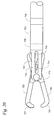
- FIG. 18 is an enlarged perspective view of the distal end portion of one embodiment of a capture device in an open configuration.
- FIG. 19 is an enlarged perspective view of the capture device of FIG. 18 in a closed configuration.
- FIG. 20 is a side elevational view of the capture device of FIG. 18 .
- FIG. 21 is a schematic of one system including electrodes operably coupled to an electrical activity (e.g., EGM) monitoring device.
- EGM electrical activity monitoring device
- FIG. 22 is a block diagram of a method and configuration to be used with the systems described herein.
- FIGS. 23-25 are block diagrams of portions of exemplary tissue capture and ligation systems.
- FIGS. 26 & 27 depict two different embodiments of ligation elements including electrodes.
- FIG. 1 One exemplary embodiment of a tissue capture system including a delivery device 10 and a capture device 20 is depicted in FIG. 1 .
- the delivery device 10 may be provided in the form of, e.g., a sheath (that may or may not be provided with an introducer/dilator as is known), catheter, or other elongate structure.
- the delivery device 10 may or may not be flexible.
- the delivery device 10 itself may preferably be steerable or deflectable.
- the delivery device 10 is also optional, i.e., the navigation and tissue capture systems described herein may not include a delivery sheath.
- the proximal end of the capture device 20 may preferably include a user interface that allows an operator to deploy and retract the capture device 20 from within the delivery device 10 , a mechanism to actuate the capture device 20 , and optionally a mechanism to steer the capture device separately from the delivery device 10 .
- the delivery device 10 includes a lumen through which the capture device 20 can be advanced or retracted to assist with delivery of the capture device 20 to a selected internal body location.
- the delivery device 10 may include as few as one lumen as depicted in FIG. 1 , it may include two or more lumens that may be used to provide pathways to deliver other devices, provide visual access, fluid access, etc.
- the capture device 20 may preferably extend out of the proximal end of the delivery device 10 such that it can be controlled by a user also operating the delivery device 10 as is conventional in the use of minimally invasive surgical devices.
- the capture device 20 is depicted in FIG. 1 in an extended configuration in which the distal end of the capture device 20 extends out of the lumen in the delivery device 10 proximate the distal end of the delivery device 10 .
- the capture device 20 is preferably movable within the lumen of the delivery device 10 such that the capture device 20 can be moved between the extended position depicted in FIG. 1 and a delivery configuration in which a distal end of the capture device 20 is contained within the lumen of the delivery device 10 .
- a potential benefit of having the capture device 20 retracted into the delivery device 10 during delivery is a reduction in the likelihood of trauma to the epicardial surface at the delivery site and on the path to the delivery site (e.g., a left atrial appendage).
- the capture device 20 depicted in FIG. 1 is in the form of a grasping apparatus that includes two jaws 22 and 24 .
- the jaws 22 and 24 can preferably be moved between on open position adapted to allow tissue to enter the space between the open jaws 22 and 24 and a closed position in the jaws 22 and 24 are moved towards each other to capture tissue that can be grasped between the jaws 22 and 24 .
- the jaws of the grasping apparatus can be actuated by any suitable technique (e.g., mechanical linkage, memory material that is closed when drawn into the delivery device, electrical activation, hydraulically, pneumatically, magnetically, etc.).
- the grasping apparatus of the capture device 20 includes two jaws, it should be understood that other grasping apparatus may be provided that include three or more jaws (and that other apparatus for capturing tissue may be used in place of, or in addition to, apparatus that use jaws).
- exemplary systems and methods are described in connection with a grasping apparatus as a tissue capture device, it should be understood that the systems and methods may be used in connection with a wide variety of capture devices.
- Potentially useful alternative capture devices may include, but are not limited to, helix groups, cryogenic tips, barbed hooks, cages, adhesive structures, suction, laser energy, RF energy, etc. Examples of some potentially suitable capture devices and/or systems may be described in U.S. Pat. Nos. 7,338,434; 7,141,057; 7,276,235; 6,206,827; etc.
- the capture device 20 depicted in FIG. 1 includes electrodes that can be used to detect EGM signals for navigating the delivery device 10 and the capture device 20 .
- the particular arrangement of electrodes depicted in connection with the system of FIG. 1 includes electrodes 32 , 34 , and 36 .
- the electrode 32 may be located on an external surface 21 of the jaw 22 (where the external surface 21 is the surface of the jaw 22 that faces away from the opposing jaw 24 ).
- the electrode 34 may be located on an internal surface 23 of the jaw 22 (where the internal surface 23 is the surface of the jaw 22 that faces the opposing jaw 24 ).
- the electrode 36 may be located on an internal surface 25 of the jaw 24 (where the internal surface 25 is the surface of the jaw 24 that faces the opposing jaw 22 ).
- the electrodes may be placed in any suitable location along the length of the jaws, e.g., the distal end, proximal end or any intermediate location.
- the proximal end of the capture device 20 preferably includes connectors connected to each electrode on the distal end of the capture device 20 by leads such that the electrodes can be connected to a system capable of generating user-readable plots of the electrical energy detected using the electrodes.
- a system capable of generating user-readable plots of the electrical energy detected using the electrodes.
- Such systems will be well-known to those of skilled in the art.
- the electrodes at the working or distal end of the capture device 20 can be used to detect the electrogram (EGM) on the epicardial surface of the patient's heart. Any or all of the electrodes may be monopolar or multipolar, as desired.
- FIG. 2A depicts another system that may be used to navigate to and capture selected tissue.
- the delivery device 110 a includes two lumens 112 a and 114 a , with the lumen 112 a preferably being used to delivery a capture device (not shown).
- the lumen 114 a is used to deliver a mapping device 140 a that, in the depicted embodiment, can be extended out of the lumen 114 a.
- the mapping device 140 a may be in the form of, e.g., a conventional electrophysiology mapping catheter.
- the mapping device 140 a may include as few as one electrode 142 a or two or more electrodes 142 a .
- the electrode or electrodes 142 a may be monopolar or multipolar.
- the delivery device 110 a could be used with a capture device deployed down the lumen 112 a as described above, the delivery device could potentially include a capture device delivered through the same lumen as the mapping device 140 a (with the mapping device being deployed, e.g., through a channel provided in the capture device itself).
- the device in FIG. 2 may be used independently to find the left atrial appendage based on the electrocardiogram (EGM) and then held in place while a second stabilization/capture device (mechanical grasper, helix group, cryo tip, barbed hook) was deployed to the same location (e.g., over the mapping device 140 a or over the delivery device 110 a ) to grab/stabilize the required tissue.
- EMM electrocardiogram
- mapping device 140 b may preferably include an electrode 142 b at its distal-most end and/or merely proximate its distal-most end.
- the capture device 120 b may include jaws 122 b and 124 b that may be used to grasp tissue as described herein.
- the jaws 122 b and 124 b and/or the delivery device 110 b may or may not include electrodes to assist with navigation.
- the capture device 120 b may include, for example, a capture shaft (see, e.g., FIGS. 18-20 ) that includes a lumen through which the mapping device 140 b can be advanced and/or retracted.
- the mapping device 140 b may be advanced ahead of the capture device 120 b to detect electrical signals in tissue that would then be contacted by the capture device 120 b if it were advanced over the mapping device 140 b.
- the depicted embodiment includes a capture device 120 b with open jaws
- the capture device may be retained in a closed position while the mapping device is advanced through the closed capture device.
- the capture device 120 b may even be retained within the delivery device 110 b while the mapping device 140 b is advanced out of the delivery device 110 b.
- FIG. 3 depicts another exemplary embodiment of a navigation and tissue capture system that includes a delivery device 210 and a capture device 220 .
- the delivery device 210 and the capture device 220 are similar to those depicted and described in connection with FIG. 1 .
- the delivery device 210 itself includes an electrode 216 located near or proximate its distal end.
- the delivery device 210 may include two or more electrodes.
- any electrodes included with the delivery device 210 may be monopolar or multipolar.
- the electrode 216 may be in the form of a ring electrode as depicted.
- the electrode or electrodes provided on the delivery device 210 may not be in the form of ring electrodes.
- the capture device 220 depicted in FIG. 3 also includes electrodes 234 and 236 on the internal surfaces of the jaws 222 and 224 .
- the capture device 220 may include other electrodes on, e.g., one or more of the external surfaces of the jaws 222 and 224 .
- the electrode 216 on the delivery device 210 may potentially be used in conjunction with electrodes 234 and 236 on the jaws 222 and 224 to improve navigation and/or to establish the position of the distal end of the capture device 220 .
- the electrode 216 on the delivery device 210 could be used by the operator to help differentiate between tissue (e.g., ventricular and atrial tissue) before the capture device 220 is extended out of the delivery device 210 .
- the distal end of the delivery device 210 could be less traumatic (e.g., softer, smoother, etc.) to the surrounding tissue (e.g., the epicardial surface of the heart) than the capture device 220 .
- the delivery device 210 (which may preferably be steerable/deflectable) could be navigated to a selected location using the electrode 216 on the delivery device 210 (while the capture device 220 and its electrodes remain in the delivery device 210 ).
- the capture device 220 may be deployed from the delivery device 210 .
- the electrode or electrodes on the capture device may then be used (alone or in conjunction with the electrode 216 on the delivery device 210 ) to navigate the capture device 220 to the selected tissue.
- the electrodes on the capture device 220 may, for example, be able to more accurately assess tissue differentiation.
- the electrode 216 on the delivery device may, for example, be monitored to determine if the delivery device 210 moves during deployment and use of the capture device 220 (for example, a change in EGM signal seen using the electrode 216 during the grasping of the left atrial appendage may indicate that the delivery device 210 has moved to a less desirable location).
- FIG. 4 A cross-sectional view of the left side of the human heart is depicted in FIG. 4 and will be used to describe operation of one embodiment of a navigation and tissue capture system.
- the heart as depicted includes the left atrium 50 and left ventricle 52 .
- the left atrial appendage 54 extends from the left atrium 50 and includes a distal tip or leading edge 56 .
- FIG. 4 Also depicted in FIG. 4 is the navigation and capture system of, e.g., FIG. 1 including a delivery device 10 and a capture device 20 .
- the capture device 20 includes an external electrode 32 on an external surface of one jaw of the capture device 20 and a pair of internal electrodes 34 and 36 on the internal surfaces of the jaws.
- the delivery device 10 is depicted as approaching the left atrial appendage 54 from the apex of the heart (which would be typical for a sub-xiphoid approach).
- the distal end of the capture device 20 is advanced along the epicardial surface (e.g., over the left ventricle 52 ) towards the leading edge 56 of the left atrial appendage 54 .
- a capture device 20 that progresses along the epicardial surface coming from the apex of the heart is primarily in contact with ventricular myocardium tissue 52 until it reaches the leading edge 56 of the left atrial appendage 54 .
- Ventricular epicardial myocardium tissue 52 produces a distinct EGM compared with the EGM produced by atrial epicardial myocardium tissue such as that found in the leading edge 56 of the left atrial appendage 54 .
- the electrodes 32 and 36 will primarily capture only ventricular EGM signals.
- the delivery device 10 may, itself, also include one or more electrodes (as, for example, described in the system of FIG. 3 ). Such electrodes may be used in addition to or in place of the electrodes on the capture device 20 (which may or may not be extended out of the delivery device 10 ).
- electrode 36 may not be in contact with any ventricular tissue and, thus, may detect a minimal EGM signal, while the electrode 32 may be in direct contact with the ventricular myocardium 52 and would likely show a strong near-field ventricular EGM signal.
- the device can optionally be designed to maintain orientation such that any one electrode could be maintained in one stationary location relative to a selected part of the anatomy.
- orientation such that any one electrode could be maintained in one stationary location relative to a selected part of the anatomy.
- an operator could, for example, monitor the electrodes 34 and 36 on both jaws of the capture device 20 to determine whether the EGM signal detected from one electrode indicates that its jaw is located closer to the ventricular tissue than the other jaw (or that both jaws show an equal signal strength indicating that both jaws are equally close to the ventricular tissue).
- the typical EGM signal associated with a normal human heartbeat includes a P wave, a QRS complex and a T wave as depicted in FIG. 5 .
- FIGS. 6A-6C depict the EGM signals that may be detected in various locations over the heart. The differences in the EGM signals can be used to determine the position of the electrodes (and thus the devices carrying them) relative to the anatomy of the heart. In some instances, it may be helpful to obtain an electrocardiogram (ECG) signal (using, e.g., surface electrodes as is known conventionally) in addition to the intracardiac EGM signals. The ECG signal may then potentially be used to assist in the navigation process (by, e.g., signal subtraction, etc.).
- ECG electrocardiogram
- FIG. 6A represents a potential EGM signal at the initial access point of the sub-xiphoid approach near the apex of the heart.
- P wave atrial EGM signal
- QRS complex strong ventricular signal
- FIG. 6B depicts a typical EGM tracing as an electrode approaches both atrial and ventricular epicardial tissue.
- the P wave 82 in FIG. 6B has a much larger amplitude as the electrodes come in contact with atrial tissue (i.e., larger than when the electrodes are at the apex of the heart as seen in FIG. 6A ).
- the QRS complex 83 of FIG. 6B continues to have a large amplitude due to continued contact with ventricular tissue.
- FIG. 6C depicts the typical EGM tracing potentially seen using electrodes that are in contact with only atrial tissue such as, e.g., the tissue of the left atrial appendage (which produces strong atrial EGM signals).
- the EGM signal of FIG. 6C shows a large amplitude P wave 84 and a relatively small amplitude QRS complex signal 85 . If the capture device is in the form of a grasping apparatus including jaws, the electrodes that could produce the signal seen in FIG. 6C may be on opposing sides of the left atrial appendage, with the left atrial appendage tissue captured between the jaws.
- capture of electrically active tissue can be distinguished from the capture of electrically inactive tissue (such as, e.g., the pericardium, epicardial fat pads, etc.) using the electrodes on the interior surfaces of the jaws.
- Distinguishing between the different EGM signals may preferably be performed by the operator (e.g., the physician), although, in some systems and methods, the distinguishing may be performed with the assistance of an automated system that compares the detected EGM signals with those associated with one or more desired outcomes.
- FIG. 7 is another cross-sectional view of a human heart depicting the left-side anatomy in which the navigation/capture system depicted in FIG. 4 is advanced further towards the left atrial appendage 54 .
- Recording electrodes 34 and 36 on the capture device 20 are in direct contact with the epicardial surface of the left atrial appendage 54 .
- the electrode 32 on the external surface of the capture device 20 is still in contact with ventricular tissue.
- the EGM signals detected from the external electrode 32 would differ from the EGM signals detected using the internal electrodes 34 and 36 .
- the different EGM signals would provide a user with the ability to determine that the capture device 20 had, in fact, captured left atrial appendage tissue.
- Left atrial appendage tissue is the first tissue that produces an atrial EGM when approaching the left atrium from the apex of the heart through a sub-xiphoid access point.
- the EGM signal detected between electrodes 34 and 36 would show a strong near-field P wave with high amplitude (atrial electrical activity) and a small amplitude QRS complex (ventricular electrical activity) as depicted in FIG. 8A .
- the external electrode 32 would show a large amplitude QRS complex and potentially and either small or large amplitude P wave depending on its contact with left atrial appendage tissue as depicted in FIG. 8B .
- the space between the epicardial surface of the heart in the pericardial sac is often full of fluid which may be electrically conductive and may distort the EGM signal slightly when not in direct contact with myocardial tissue.
- FIG. 7 provides an opportunity to visualize how the systems and methods described herein may allow the operator to navigate from the apex of the heart (where initial contact is with the epicardial surface during a sub-xiphoid approach) to the tip of the left atrial appendage.
- the delivery device 10 and associated capture device 20
- the initial EGM signals will indicate contact with ventricular tissue (see, e.g., FIG. 6A ).
- the first EGM signal indicating contact with atrial tissue when approached from the apex of the heart should be the tissue of the left atrial appendage.
- EGM signals during the procedure may be obtained using other imaging/guidance modalities such as, e.g. fluoroscopy, direct visualization, ultrasound imaging, MRI imaging, CT scans, etc.
- the use of a secondary imaging/guidance technique may be used to potentially confirm capture of the left atrial appendage by, e.g., providing information regarding the angle of closure of the jaws of a grasping apparatus, etc. If, for example, no tissue is captured, then the jaws of a grasping apparatus may close completely. When tissue is present, the jaws will typically not close completely.
- FIG. 9 depicts a situation in which the capture device 20 (and associated delivery device 10 ) of FIG. 4 is advanced towards the left atrial appendage, but is closed without capturing the tissue of the left atrial appendage.
- One potential benefit of using EGM signals to navigate to and/or confirm capture of the left atrial appendage tissue is that when the electrodes on a capture device 20 close without capturing tissue between them, the EGM signal would not show a strong amplitude P wave. Rather, the electrodes 34 and 36 would be expected to short out and show a flat line EGM signal as depicted in FIG. 10A because the electrical potential across the electrodes 34 and 36 is zero.
- the external electrode 32 on the capture device 20 would typically be expected to show a large amplitude QRS complex and potentially and either small or large amplitude P wave depending on its contact with left atrial appendage tissue as depicted in FIG. 10B .
- FIG. 11 depicts another situation in which the capture device 20 (and associated delivery device 10 ) are advanced too far.
- the capture device 20 When the capture device 20 is advanced past the tip of the left atrial appendage that is closest the apex of the heart, it will likely not come into contact with any other atrial tissue. Any tissue that is captured by the capture device 20 as depicted in FIG. 11 will have an non-atrial EGM signal.
- the electrodes 34 and 36 on the capture device 20 may, for example, reflect an EGM signal of the pericardium or far-field ventricular and/or atrial signals.
- the external electrode 32 on the capture device 20 may reflect a strong atrial EGM signal given that it may still be in contact with the left atrial appendage as the capture device 20 passes over the appendage (which may be an indication that the capture device 20 is incorrectly positioned).
- the external electrode 32 should detect at least some ventricular EGM signal as discussed herein.
- FIG. 12 depicts another situation in which the capture device 20 (and associated delivery device 10 ) are advanced into a position that is not amenable to proper capture of the left atrial appendage.
- the capture device 20 is depicted as advanced beneath the tip of the left atrial appendage, such that the capture device 20 is located between the left atrial appendage and the underlying ventricular tissue.
- Tissue that is captured when the capture device 20 is beyond the position depicted in FIG. 12 could likely be ventricular tissue with a ventricular EGM signal across electrodes 34 and 36 on the capture device 20 .
- the EGM signals from the electrodes 34 and 36 on the capture device showed both atrial and ventricular signatures as depicted in, e.g., FIG. 13A .
- the external electrode 32 may, if it located nearest the ventricular tissue, show an EGM signal weighted towards the QRS complex portion of the complete EGM signal as depicted in FIG. 13B .
- the situation depicted in FIG. 12 may not, however, be entirely hopeless.
- the capture device 20 could potentially capture a lobe of the left atrial appendage and this could be a clinically acceptable outcome. Confirmation of this outcome could potentially be obtained by, e.g., detecting a strong atrial EGM signal (see, e.g., FIG. 6C ) using the electrodes 34 and 36 on the capture device 20 .
- FIG. 14 depicts another exemplary embodiment of a delivery device 310 and a capture device 320 similar to those depicted in FIGS. 1 and 3 .
- the electrodes 316 and 318 on the delivery device 310 and the electrodes 332 , 333 , 334 , and 335 on the capture device 320 are all ring electrodes.
- the ring electrodes 316 and 318 on the delivery device 310 could, however, be used in conjunction with electrodes on the jaws 322 and 324 to improve navigation to the left atrial appendage by potentially more precisely establishing position of the distal ends of the jaws 322 and 324 of the capture device 320 .
- Any or all of the electrodes could be monopolar or multipolar.
- the electrodes 316 and 318 on the delivery device 310 could be used by the operator to help differentiate between the ventricular and atrial tissue as the delivery device 310 is advanced. Additional specificity of EGM interpretation is potentially feasible with the electrode configuration depicted in FIG. 14 . For example, reading a bi-polar signal across electrode 332 and 334 on jaw 322 or electrode 335 and 336 on jaw 324 may allow the operator to better confirm the presence of particular types of tissue within the capture device 320 (i.e., ventricular tissue versus atrial tissue).
- the electrodes on the jaws 322 and 324 of the device depicted in FIG. 14 may also create a near-field EGM.
- the near-field EGM signal may produce a cleaner and easier to interpret EGM signal for determination of tissue type.
- the ring electrodes 316 and 318 on the delivery device 310 could be used for navigation in the pericardial space in a similar manner as described above for the device depicted in FIG. 3 , yet with the potential for a more precise near-field EGM created from the two ring electrodes 316 and 318 .
- FIG. 15 Another potential embodiment depicted in FIG. 15 includes ring electrodes 416 and 418 on the delivery device 410 .
- the electrodes 433 , 434 , 436 , and 437 on the internal surfaces of the jaws 422 and 424 could be used to help better navigate and position the capture device 420 .
- the external electrodes 432 and 435 on the external surfaces of the jaws 422 and 424 could be used to differentiate tissue on the external surface of the jaws 422 and 424 from that in contact with the internal surfaces of the jaws. Electrodes 433 and 434 on jaw 422 and electrodes 436 and 437 on jaw 424 only capture the near-field EGM signal on the internal grasping surfaces of the jaws.
- External electrodes 432 and 435 may be used to determine the position of the capture device 420 relative to the pericardium, ventricular tissue underneath the LAA or any other tissue. Any or all of the electrodes could be monopolar or multipolar.
- the configuration of electrodes on the capture device 420 may provide additional specificity of EGM interpretation versus the configuration seen in the device of FIG. 14 .
- the ring electrodes 416 and 418 on the delivery device 410 could again be used for navigation in the pericardial space in a similar manner as described for similar arrangements herein (with the potential for a more precise near-field EGM read from the two ring electrodes 416 and 418 ).
- tissue capture systems described herein may be integrated into known tissue capture systems. Examples of some potentially suitable tissue capture systems including delivery devices and capture devices may be described in U.S. Patent Application Publication No. US 2007/0073313 (Liddicoat et al.).
- a capture device 520 according to the principles described in Liddicoat et al. may, for example, include electrodes 530 integrated with the supports or guides included in the disclosed devices.
- the capture device 520 may preferably be delivered using a delivery device 510 .
- an optional guide element 540 which may include an electrode 542 in place of or in addition to a magnet as described in Liddicoat et al. If the guiding element 540 is provided with an electrode 542 , the electrodes 530 on the capture device 520 may be optional.
- FIG. 17 depicted in the form of a catheter that includes a lumen that may be used to provide suction to capture tissue.
- the capture device 620 may include one or more electrodes 630 proximate (at or near) the distal end of the catheter to detect physiological electrical activity to guide the capture device as described herein.
- the capture device 620 may also (or alternatively) include one or more electrodes that are spaced from the distal end of the capture device 620 as described herein with respect to, e.g., the embodiments depicted in FIGS. 18-20 .
- the capture device 720 includes a first jaw 722 and a second jaw 724 .
- the first and second jaws 722 and 724 may be mounted on the distal end of a capture shaft 726 that can be used to advance the capture device 720 through the lumen of an introducer, endoscope, catheter, trocar, etc. that can provide access to a selected internal body location.
- the capture devices of systems and methods described herein may preferably operate in an atraumatic manner to capture tissue.
- atraumatic and variations thereof means that the capture devices described herein, when used to capture tissue, do not cut, sever, or remove the captured tissue.
- the capture devices used in connection with the systems and methods described herein can be distinguished from conventional biopsy devices because the capture devices described herein preferably do not cut, sever, and/or remove of tissue as would conventional biopsy devices.
- the capture devices may, however, include retention structures/features such as serrations, teeth, roughened surfaces, posts, pins, adhesives, etc. that contribute to the ability of the capture devices to maintain attachment to tissue captured within the jaws while still remaining an atraumatic device.
- one example of a retention structure is found in the complementary teeth 727 found on the jaws 722 and 724 .
- the depicted retention structure includes one tooth 727 located on the first jaw 722 and two teeth 727 located on the second jaw 724 .
- the tooth 727 on jaw 722 may preferably nest within the pair of teeth 727 to assist in retaining tissue within the capture device 720 .
- the first jaw 722 of capture device 720 has an interior surface 723 that faces the interior surface 725 of the opposing second jaw 724 . Also included in the depicted embodiment of capture device 720 is a first electrode 734 positioned on the interior surface 723 of the first jaw 722 and a second electrode 736 positioned on the interior surface 725 of the second jaw 724 .
- the capture device 720 may have a closed configuration in which the jaws are closed such that the interior surfaces 723 and 725 of the first and second jaws 722 and 724 move towards each other and an open configuration (see, e.g., FIG. 18 ) in which the first and second jaws are open and spaced apart such that the capture device can capture tissue between the jaws 722 and 724 .
- the capture device may optionally include a mechanism to lock the jaws in the closed configuration such that a user is not required to continually hold the capture device 720 in the closed configuration.
- the locking mechanism may preferably be operable from the proximal end of the capture device.
- the locking mechanism may take the form of a biased (e.g., spring-loaded, etc.) mechanism that holds the jaws of the capture device in a closed configuration in the absence of any intervening force that is applied to open the jaws. Such an embodiment may be referred to as having “normally-closed” jaws.
- the jaws of a capture device may alternatively be biased (e.g., spring-loaded, etc.) in an open configuration in the absence of an intervening force that is applied to close the jaws.
- Such an embodiment may be referred to as having “normally-open” jaws.
- Such jaws may be closed to capture tissue using any suitable mechanism including, but not limited to a sheath that can be advanced distally over the jaws, thereby urging them into a closed configuration.
- the capture device 720 may also have a delivery configuration in which the distal end of the capture device 720 (typically the jaws 722 and 724 ) is contained within the capture lumen of a delivery device such as a sheath, introducer, endoscope, catheter, trocar, etc.
- the capture device may further have an extended configuration in which the distal end of the capture device 720 extends out of the capture lumen of a delivery device proximate the distal end of the delivery device. This concept is also described above in connection with FIG. 1 .
- the jaws 722 and 724 are both attached for rotation about an axis 702 that is oriented generally transverse to a longitudinal axis 701 that extends from a proximal end to a distal end of the capture shaft 726 .
- the axis of rotation 702 about which the jaws 722 and 724 rotate may not necessarily be exactly transverse to the longitudinal axis 701 in any or all planes that contain the longitudinal axis 701 .
- FIGS. 18-20 depict only one example of a potentially suitable mechanism.
- rotation of the jaws 722 and 724 about the axis 702 means that the jaws 722 and 724 are pivotally mounted on a main rivet 740 that extends through arms 742 that extend from the capture shaft 726 .
- Axis 702 (about which the jaws 722 and 724 rotate) preferably extends through the main rivet 740 .
- Rotation of the jaws 722 and 724 about the axis 702 is effected in the depicted embodiment by moving a link rivet 744 through slots 743 formed in arms 742 . Movement of the link rivet 744 is effected, in the depicted embodiment, by moving an actuator such as a drive rod 741 through an actuator lumen in the capture shaft 726 , with the link rivet 744 being attached to the drive rod 741 .
- the link rivet 744 also extends through slots 745 and 747 located in the jaws 722 and 744 .
- the link rivet 744 is advanced distally towards the distal end of the capture device 720 (see, e.g., FIGS. 18 and 19 ), the jaws 722 and 724 open. Conversely, as the drive rod 741 and attached link rivet 744 are moved proximally, the jaws 722 and 724 close (see, e.g., FIG. 20 ).
- the capture device 720 also includes a variety of electrodes that can be used to monitor EGM signals.
- the depicted embodiment of the capture device 720 includes a first electrode 732 located on the interior surface 723 of the first jaw 722 and a second electrode 734 located on the interior surface 725 of the second jaw 724 .
- a first electrode lead 733 extends from the first electrode 732 towards a proximal end of the capture device 720 .
- the first electrode lead 733 is connected to the electrode 732 , in the depicted embodiment, through the jaw 722 with a similar lead being located on the second jaw 724 (but not depicted in FIGS. 18 and 19 ).
- the leads may preferably extend through the capture shaft 726 where they terminate at an EGM monitoring apparatus connector (not seen).
- a potential alternative structure for electrically connecting the electrodes 732 and 734 without using separate and discrete leads as seen in FIGS. 18 and 19 may include placing the main rivet 740 in electrical communication between a coil (other conductor) extending through the capture shaft 726 , the first jaw 722 , and electrode 732 .
- the main rivet 740 is preferably electrically isolated from the second jaw 724 and its electrode 734 by any suitable technique, e.g., insulating washers, bushings, etc. (which may be constructed of dielectric materials such as, e.g., polyimides, PEEK, etc.).
- the link rivet 744 may serve as the path for electrical communication between another lead (such as the drive rod 741 ), the second jaw 724 , and electrode 734 .
- the link rivet 744 may also be electrically isolated from the first jaw 722 and its electrode 732 by any suitable technique, e.g., insulating washers, bushings, etc. (which may be constructed of dielectric materials such as, e.g., polyimides, PEEK, etc.).
- the jaws 722 and 724 may be made of electrically conductive materials (such as, e.g., metals, etc.), they may be coated with nonconductive materials such that, e.g., the electrodes 732 and 734 on selected surfaces, e.g., the outer surfaces, etc.
- nonconductive materials may include polymers, paints, epoxies, etc. Insulating the outer surfaces and other areas of the capture devices may potentially enhance the ability of the system to capture and/or distinguish EGM signals of tissue located within the capture device.
- the electrodes provided on the capture devices may be in the form of discrete electrodes that are attached to the capture device (e.g., a jaw, etc.) as depicted in, e.g., FIGS. 18-19 .
- the capture device elements on which the electrodes are placed are electrically conductive, the electrodes may be electrically isolated from the capture device.
- the electrodes 732 and 734 may, in some embodiments, be located on the interior surfaces 723 and 725 of the jaws 722 and 724 such that the electrodes are located opposite from each other. In such a configuration, closure of the jaws 722 and 724 in the absence of tissue or other material located therein may preferably result in electrical communication between the electrodes, e.g., the electrodes 732 and 734 may “short out” when the jaws 722 and 724 are closed. Such an event may be useful for providing an indication to a user that not tissue has been captured by the capture device 720 .
- the electrodes used on the jaws of the capture device 720 may occupy substantial portions of the interior surfaces of the jaws.
- the electrodes 732 and/or 734 occupy about one quarter or more of the interior surfaces 723 and 725 of the jaws.
- at least one of the electrodes provided on the interior surface of a jaw occupy about one half or more of the interior surface of the jaw.
- the capture device 720 includes a pair of electrodes, with one electrode located on each jaw, it should be understood that that many different electrode configurations are possible. For example, only one electrode may be provided such that, e.g., only one of the jaws carries an electrode (with a return electrode located elsewhere, e.g., on the capture shaft, an exterior surface of one of the jaws, on a delivery device, etc.). In some embodiments, for example, an electrode is coupled to the interior surface of a first jaw and the interior surface of a second jaw is free of any electrodes.
- two or more electrodes may be placed on one jaw (on, e.g., the interior surface of the jaw), while the other jaw contains no electrodes.
- the two or more electrodes may be provided in any suitable configuration, e.g., they may be arranged along a straight line, in a circle, randomly, etc.
- An example of an embodiment in which only one of the jaws carries electrodes may be seen with reference to FIG. 15 where the capture device 420 may be provided with only one set of interior electrodes (e.g., only electrodes 433 and 434 , but not electrodes 436 and 437 ).
- the opposing interior surface of the opposing jaw may be electrically conductive such that closure of the jaws places the two electrodes in electrical communication with each other (i.e., shorts out the electrodes) to provide an indication that no tissue is captured between the jaws.
- the electrically conductive interior surface may be inherent in the opposing jaw (if, e.g., the interior surface was exposed metal or some other conductive material) or the opposing interior surface may be provided with a conductive element on its interior surface that is placed to provide the desired shorting out function.
- the capture shaft 726 includes a pair of shaft electrodes 736 and 738 .
- the shaft electrodes 736 and 738 may be used to, e.g., monitor the type of tissue in contact with the shaft 726 .
- the EGM signals picked up by electrodes used with the capture devices described herein can be useful in determining the location of the device within, e.g., the pericardial space.
- the shaft electrode(s) 726 may potentially be used in the same manner as the external electrodes on capture devices described in connection with FIGS. 4-13 .
- the shaft electrodes 736 and 738 may or may not be provided in the form of ring electrodes that extend around the perimeter of the shaft 726 .
- the electrodes 736 and 738 may preferably be electrically isolated from the remainder of the capture device 720 and be placed in electrical communication with EGM monitoring apparatus through leads that extend proximally through the capture shaft 726 .
- the capture devices may be provided with only one shaft electrode, three or more shaft electrodes, and even no shaft electrodes. If provided, the one or more shaft electrodes may preferably be located within a distance of about 10 centimeters (cm) or less, about 5 cm or less, or even about 2 cm or less from the distal end of the capture device such that the EGM signals detected using the shaft electrodes are those that are indicative of the tissue proximate the working portion of the capture device.
- the function of the shaft electrodes may, in some instances be provided and/or supplemented by using one or more electrodes at other locations, e.g., electrodes located on a delivery device used to deliver the capture device, electrodes on exterior surfaces of the jaws or any other element of any other capture device, electrodes on the skin or at other locations on the subject, etc.
- the capture devices depicted in FIGS. 18-20 and elsewhere herein include two jaws, both of which may be moved to change between an open and closed configuration, it should be understood that the captured devices may include more than two jaws, e.g., three, four or more jaws. In still other variations, one or more of the jaws may be stationery while one or more of the remaining jaws moves to changed between the open and closed configurations.
- the jaw 722 may be stationary with respect to the capture shaft 726 , while jaw 724 rotates to move the capture device between the open and closed configurations.
- An exemplary embodiment of an additional method of navigating a device to an anatomical structure may include delivering a device into an anatomical space (e.g., the pericardial sac); injecting image enhancement liquid (e.g., a liquid contrast agent in the case of fluoroscopy, echogenic liquids for use in conjunction with ultrasonic imaging, etc.) into the anatomical space (e.g., the pericardial sac); and identifying the location of the device and/or the locations of anatomical structures (e.g., the left atrial appendage) using any appropriate imaging modality, e.g., fluoroscopic visualization, MRI, CT scanning, etc.
- this method and apparatus used to perform it could be used alone, i.e., without the aid of EGM-based navigation.
- LAA left atrial appendage
- the depicted system includes a capture device 1110 having one or more electrodes 1130 and connector 1140 connected to the electrodes 1130 through leads 1131 .
- the depicted system optionally also includes a delivery device 1112 that may include an electrode 1132 (or more than one electrode) and a connector 1142 connected to the electrode 1132 through a lead 1133 .
- the system further optionally includes ligation element 1114 that may include a ligation element electrode 1134 (or more than one electrode) and a connector 1144 connected to the electrode 1134 through a lead 1135 .
- the ligation element 1114 may be configured to ligate body tissue (e.g., the LAA)
- the connectors 1140 , 1142 , and 1144 may be adapted to connect to an electrical (e.g., EGM, etc.) monitoring apparatus 1100 through connectors 1150 , 1152 , and 1154 .
- an electrical e.g., EGM, etc.
- innate electrical signals that may be detected by the electrodes may be monitored, displayed, analyzed, filtered, stored, manipulated, enhanced, etc. to assist a user in navigating the delivery device and/or capture device as described herein.
- the connectors may take any suitable form, e.g., plugs, sockets, bare wires, snap-fit connectors, etc.
- Systems and/or methods described herein may be used to capture and/or to occlude body tissue, e.g., the LAA.
- Navigation of the capture and/or ligation devices may be performed using various characteristics of the body tissue being captured.
- the impedance of body tissue e.g., the LAA
- these impedance changes can potentially be used as the basis for navigating to and/or capturing selected tissue.
- the impedance differences can also be used in some systems and methods to control the forces exerted on the selected tissue by capture and/or ligation devices.
- the impedance characteristics of tissue subjected to forces by a capture device and/or ligation element may provide insight as to whether or not the force is clinically safe or potentially puts the patient at risk.
- FIG. 22 can be used to describe one configuration and method of utilizing the systems described herein (e.g., the system described with reference to FIGS. 1-21 ) that may use the impedance of body tissue for navigation, capture, and/or occlusion control as discussed herein.
- electrical monitoring apparatus e.g., electrical monitoring apparatus 1100
- a capture device e.g., capture device 1110
- a selected tissue e.g., atrial tissue, ventricular tissue, etc.
- measured impedance may be used to exclude certain tissues rather than confirm capture.
- fat may have an extremely high impedance and myocardium may have a much lower impedance.
- measured impedance could be used to exclude certain types of tissue rather than be certain of inclusion of different types of tissue.
- the capture device used in connection with electrical monitoring apparatus 1100 may include a first jaw and a second jaw where the first jaw and the second jaw include an open configuration in which the first jaw and the second jaw are open and a closed configuration in which the first jaw and the second jaw are closed (e.g., the interior surface of the first jaw is located closer to an interior surface of the second jaw when the first jaw and the second jaw are in the closed configuration than when the first jaw and the second jaw are in the open configuration).
- the first electrode may be coupled to the interior surface of the first jaw and the second electrode may be coupled to the interior surface of the second jaw (e.g., the electrodes face one another in at least one configuration).
- the electrical activity of the body tissue may exhibit variations, which may be consistent with compression, ischemia and/or trauma of the body tissue (e.g., in the case of LAA capture, a small ST segment elevation may exist). Further, a substantial decrease in the electrical activity of the body tissue may indicate that the body tissue is sufficiently ligated to, in the case of, e.g., the left atrial appendage, limit flow of blood into the appendage.
- the impedance of tissue (e.g., the left atrial appendage) being occluded may provide an indication as to the forces applied to the tissue.
- a threshold value may be obtained during the procedure itself in the form of a baseline value, with subsequent measurements being compared to the (baseline) threshold to determine when the differential between a current measurement and the threshold value exceeds a predetermined limit, then an indication can be made that occlusion is sufficient, etc.
- the absolute value of the measured impedance may be dependent on a variety of factors such as, e.g., the size of the patient, the size of any reference electrodes/patches that are being used, etc. As such, absolute measurements may be of less importance than the changes in the impedance values over time. Changes in measured impedance during the occlusion process (e.g., from the start of occlusion to the end), as discussed herein, may provide an indication that occlusion has reached a selected limit. Such changes in impedance may occur during occlusion as a result of, e.g., extra-cellular fluid accumulation due to cell death or cell rupture, etc.
- an increase in measured impedance of the tissue being occluded of, e.g., 15% or more, 25% or more, etc. may be used as an indication that sufficient occlusion has been obtained and, thus, occlusion should be halted.
- Lack of electrical activity in the captured and/or ligated tissue may be used to confirm that the tissue (e.g., the left atrial appendage) is ischemic, at which point the process can be halted to, e.g., prevent over-tightening. If the tissue, such as the left atrial appendage is being occluded during pacing, pacing capture may be lost when tissue becomes ischemic due to the occlusion forces. In some embodiments, the time between starting occlusion and when complete occlusion and, thus, loss of pacing capture occurs is relatively brief.
- the system is configured to determine when the EGM signal decreases be a predetermined or threshold value (e.g., 10%, 20%, 30%, etc.) and the pacing capture threshold increases by a predetermined or threshold value (e.g., 10%, 20%, 30%, etc.) and/or pacing is lost.
- the system may be configured to make a determination that occlusion is sufficient and no further occlusion should be performed. These measurements may further be correlated with measured impedance of the captured tissue (as discussed herein) as a further indication that sufficient occlusion has been performed.
- the left atrial appendage may appear to have residual flow using another monitoring technique (e.g., Trans-Esophageal Echo (TEE), Intra-Cardiac Echo (ICE), Doppler, etc.) but the EGM signals may have attenuated to near zero.
- TEE Trans-Esophageal Echo
- ICE Intra-Cardiac Echo
- Doppler Doppler
- the operator may have an indication that the left atrial appendage tissue has become ischemic even though the appendage has not been closed sufficiently to prevent flow. In this situation, the operator may decide to cease tightening suture any further and investigate why there is residual flow.
- EGM signals in the left atrial appendage may attenuate to zero at approximately the same time as the ostium closes under normal circumstances. Any variation from this could provide the basis for a determination that something out of the ordinary has occurred. If the capture device has captured annular fat then, despite tightening, there would be no decrease in the electrogram and no change in the far field electrograms being picked up. If the capture device has captured ventricular myocardium (e.g., aneurysm or diverticulum), then the large electrogram would not decrease with appendage occlusion.
- ventricular myocardium e.g., aneurysm or diverticulum
- the operator could use flow detection within the appendage (e.g., TEE, ICE, Doppler, etc.) as the primary indication of closure of the appendage and then continue tightening until the EGM signals attenuate.
- flow detection within the appendage
- EGM signal attenuation might prevent over tightening and accidental ripping/tearing of the left atrial appendage tissue.
- the capture device may include the first electrode and a ligation element (e.g., configured to ligate body tissue that may be captured by the capture device) that may include the second electrode with, e.g., the two electrodes being used to measure an impedance across body tissue, to measure electrical activity, etc.
- the electrical monitoring apparatus may be further configured to determine whether the ligation element is located proximate selected tissue (e.g., atrial tissue, ventricular tissue, etc.) based on monitoring electrical activity using at least one electrode as described herein.
- the electrical monitoring apparatus may be configured to compare the monitored electrical activity to a threshold value and determine whether the body tissue has been ligated based on the based on the comparison between the monitored electrical activity and the threshold value.
- Monitoring of tissue impedance between a first electrode and a second electrode by the electrical monitoring apparatus 1100 may be performed using various techniques.
- the electrical monitoring apparatus may be configured to monitor the impedance between a first electrode and a second electrode by monitoring the impedance at one or more selected frequencies and/or one or more selected amplitudes between the first electrode and the second electrode. Using different combinations of frequencies and amplitudes may be assist in delineating between various types of tissue. For example, the impedance of atrial tissue may respond differently at higher frequencies then ventricular tissue.
- determining whether the capture device and/or ligation element is proximate selected tissue based on the monitored impedance may be performed using various techniques.
- navigation to selected tissue such as, e.g., the left atrial appendage, may be performed by monitoring impedance of the tissue proximate selected electrodes.
- the electrical monitoring apparatus may be configured to determine whether the capture device is proximate selected tissue based on the monitored impedance by comparing the monitored impedance to a known value, a threshold value, etc., wherein the known and/or threshold values may be acquired by monitoring the impedance of the selected tissue, or may otherwise be predetermined (e.g., historically, empirically, etc.).
- the monitored impedance may be used in various ways other than determining whether the capture device and/or ligation element is located proximate the selected tissue.
- the impedance as measured by the electrical monitoring apparatus may be used as an indication of the force being applied to the selected tissue by the capture and/or ligation devices. That information may be used to control the amount of force applied by the capture and/or ligation devices.
- a capture device may be tightened on or around body tissue during the capture process while the impedance of the tissue is being monitored to provide an indication as to the force being applied to the tissue.
- the electrical monitoring apparatus may be configured to provide a signal to the user (e.g., through a sound, visual cue, etc.) that the body tissue has been sufficiently captured.
- the signal may be triggered based on the monitored impedance of the tissue, with the monitored impedance being compared to a threshold value, a known value, etc. as discussed herein.
- the system may be configured to provide the signal to a user before body tissue is undesirably damaged by the application of excessive force.
- FIG. 23 depicts a portion of an exemplary tissue capture system 1300 that includes force-limiting apparatus and/or actuation apparatus.
- the system includes a capture device 1310 configured to capture body tissue; a capture shaft (not shown) including an elongated body including a proximal end and a distal end, wherein the distal end of the capture shaft is coupled to the capture device 1310 ; a ligation element 1320 configured to ligate the body tissue; and force-limiting apparatus 1330 .
- the force-limiting apparatus 1330 may, in some embodiments, be operably coupled to the ligation element 1320 to restrict the amount of force applied by the ligation element 1320 when the ligation element 1320 is tightened around body tissue. In some embodiments, the force-limiting apparatus 1330 may be operably coupled to the capture device 1310 to restrict the amount of force applied by the capture device 1310 to the body tissue. In still other embodiments, a force-limiting apparatus 1330 may be operably coupled to both the capture device 1310 and the ligation element 1320 .
- the force-limiting apparatus 1330 may be found in any suitable location, i.e., proximate a capture device and/or ligation element, in a shaft carrying a capture device and/or ligation element, at a proximal end of the shaft carrying the capture device and/or ligation element (e.g., in a handle), etc.
- the force-limiting apparatus 1330 may be electrically controlled (e.g., by electrical monitoring apparatus) and/or include one or more mechanical and/or electrical devices, e.g., a slip clutch, a spring, a ratchet mechanism with a force limiting pawl, etc. may be operably coupled to the ligation element 1320 and/or capture device 1310 .
- the force-limiting apparatus 1330 may include a spring operably coupled to the first jaw and/or the second jaw such that the spring operates to keep the first jaw and the second jaw in a normally closed configuration (e.g., thereby limiting the grasping force of the capture device).
- biasing elements e.g., springs, magnets, etc.
- Any spring, magnet, or other biasing element that may be used to provide a normally-closed capture device may be located proximate the capture device itself and/or proximally of the capture device itself, e.g., in the shaft or at the proximal end of the shaft carrying the device (in, e.g., the handle).
- the force limiting apparatus may provide feedback in the form of, e.g. visual, audible, tactile, etc. alerts that signal to a user that desirable limits are being reached or have been reached.
- the feedback may also or alternatively be automated such that, once a determination has been made that the predetermined force limits have been reached, the system may include an automated force-limiting mechanism such that no further increases in the applied force are possible.
- electrical monitoring apparatus may be operably coupled to the force-limiting apparatus 1330 and configured to use the force-limiting apparatus 1330 to control forces applied by the capture devices 1310 and/or the ligation elements 1320 .
- the electrical monitoring apparatus may be configured to use the force-limiting apparatus 1330 to restrict the amount of force applied by the ligation element 1320 when the ligation element 1320 is tightened around body tissue or applied by the capture device 1310 when the capture device 1310 is capturing body tissue (e.g., based on a monitored impedance as described with respect to FIG. 22 ).
- the system 1300 may further include actuation apparatus 1340 operably coupled to the capture device 1310 and/or ligation element 1320 .
- the actuation apparatus 1340 may be, in some embodiments, configured to actuate the capture device 1310 to capture body tissue (e.g., the LAA).
- the actuation apparatus 1340 may, in some embodiments, be configured to tighten and/or loosen the ligation element 1320 around body tissue (e.g., the LAA).
- the actuation apparatus 1340 may be operably coupled to electrical monitoring apparatus, which may be further configured to actuate the capture device 1310 to capture the body tissue using the actuation apparatus 1340 and/or tighten the ligation element 1320 around the body tissue using the actuation apparatus 1340 , e.g., based on a monitored impedance as described with respect to FIG. 22 , monitored electrical activity, etc.
- system 1300 depicts a single actuation apparatus 1340 and a single force-limiting apparatus 1330 in use by both the capture device 1310 and the ligation element 1320
- two or more actuation apparatus 1340 and/or two or more force-limiting apparatus 1330 may be used in connection with system 1300 .
- the ligation element 1320 may be operably coupled to a first actuation apparatus and/or a first force-limiting apparatus and the capture device 1310 may be operably coupled to a second actuation apparatus and/or a second force-limiting apparatus.
- connection lines, the force-limiting apparatus 1330 , and the actuation apparatus 1340 as depicted in FIG. 23 are dashed representing that such connections and apparatus may be optional.
- the system 1300 may include force-limiting apparatus 1330 operably coupled to only the ligation element 1320 and not include an actuation apparatus 1340 .
- the system 1300 may include force-limiting apparatus 1330 operably coupled to both of the ligation element 1320 and the capture device 1310 and actuation apparatus 1340 only operably coupled to the capture device 1310 .
- FIG. 24 depicts a portion of another exemplary tissue capture system 1400 .
- the system 1400 may include a capture device (not shown) configured to capture body tissue as described herein; a capture shaft (not shown) including an elongated body including a proximal end and a distal end, wherein the distal end of the capture shaft is coupled to the capture device; electrical monitoring apparatus 1405 ; and one or more optional sensor apparatus 1407 that may be operably coupled to the electrical monitoring apparatus 1405 .
- the one or more sensor apparatuses 1407 may be used to sense or monitor one or more different characteristics that may be used for navigation, capture, and/or force control of selected tissue. As depicted in FIG.
- the system includes flow-sensing apparatus 1410 , pressure-sensing apparatus 1420 , temperature-sensing apparatus 1430 , motion-sensing apparatus 1440 , and pulse oximetry apparatus 1450 .
- the sensor apparatus 1407 may also include one or more electrodes that can be used to measure impedance or other electrical characteristics as discussed herein.
- the flow sensing apparatus 1410 may be operably coupled to the capture device such that the electrical monitoring apparatus 1405 may use the flow-sensing apparatus 1410 to measure fluid flow within the captured tissue (e.g., within the left atrial appendage).
- the flow-sensing apparatus 1410 may include one or more flow sensors (e.g., Doppler probes) mounted either directly on the capture and/or ligation devices and appropriate apparatus needed to detect fluid flow using the flow sensors. If, during occlusion, the sensed fluid flow abruptly decreases and/or reaches zero, the system can be configured to make a determination that occlusion has been completed.
- Flow sensing may be used in combination with one or ore other techniques described herein to address those situations in which, for example, the flow-sensing apparatus is measuring flow in a volume that is not being occluded (e.g., in a neighboring vessel, etc.) and occlusion is complete, but the flow-sensing apparatus is still indicating the presence of fluid flow despite occlusion.
- the pressure-sensing apparatus 1420 may be operably coupled to the capture device such that the electrical monitoring apparatus 1405 may use the pressure-sensing apparatus 1420 to measure the amount of pressure applied by the capture device, e.g., to body tissue.
- the pressure sensing apparatus 1420 may include one or more pressure sensors mounted either directly on the capture and/or ligation devices and appropriate apparatus needed to detect pressure using the pressure sensors.
- the pressure-sensing apparatus 1420 apparatus may include sensors operably coupled to the first jaw and/or the second jaw so as to measure the pressure applied between the first jaw and the second jaw. Such pressure measurement may be useful to apply a sufficient amount of “grasping” force with the capture device to capture a selected body tissue (e.g., the LAA).
- a selected body tissue e.g., the LAA
- the electrical monitoring apparatus 1405 may be configured to compare the monitored pressure applied by the capture device to a threshold value and determine whether the body tissue is captured by the capture device based on the comparison between the monitored pressure and the threshold value. Further, for example, if the pressure is below a predetermined threshold value, then it may be desirable to increase the force applied by the capture device to assist the capture device in holding position so that it is less likely to dislodge from or release the captured tissue during subsequent procedures. If the pressure is above a predetermined threshold value, it may be desirable to decrease the pressure applied by the capture device to, e.g., limit or prevent trauma of the captured body tissue.
- the electrical monitoring apparatus 1405 may be further configured to report to a user the amount of pressure applied by the capture device and record the pressure applied by the capture device to, e.g., provide guidance to a user.
- the monitored pressure may be used to limit the amount of force applied by the capture device and/or a ligation element using a force-limiting apparatus 1330 as described herein with reference to FIG. 23 .
- the force-limiting apparatus 1330 may be operably coupled to the pressure sensing apparatus 1420 (e.g., through the electrical monitoring apparatus 1405 ) and to the capture device and/or ligation element to restrict the amount of force/pressure applied by the capture device and/or ligation element to the body tissue.
- the monitored pressure may be used to control an actuation apparatus 1340 as described herein with reference to FIG. 23 .
- the actuation apparatus (not shown) may be operably coupled to the pressure sensing apparatus 1420 (e.g., through the electrical monitoring apparatus 1405 ) and to the capture device and/or ligation element to restrict the amount of force/pressure applied by the capture device and/or ligation element to the body tissue by controlling the actuation apparatus itself.
- the actuation apparatus may be configured to actuate the capture device to capture the body tissue based on the amount of pressure applied by the capture device as monitored by the pressure-sensing apparatus 1420 .
- the actuation apparatus may be configured to operate the ligation element based on the amount of pressure applied by the capture device as monitored by the pressure-sensing apparatus 1420 .
- the system may include temperature-sensing apparatus 1430 .
- the temperature-sensing apparatus 1430 may be operably coupled to the capture device such that the electrical monitoring apparatus 1405 may use the temperature-sensing apparatus 1430 to measure the temperature of the body tissue captured by the capture device.
- the temperature sensing apparatus 1430 may include one or more temperature sensors mounted either directly on the capture and/or ligation devices and appropriate apparatus needed to detect temperature of tissue using the temperature sensors.
- the temperature-sensing apparatus 1430 apparatus may include temperature sensors operably coupled to the first jaw and/or the second jaw so as to measure the temperature of tissue in contact with the temperature sensors.
- the temperature-sensing apparatus may be provided in the form of, e.g., infrared temperature sensors with the infrared sensors located at any appropriate location on the capture devices, ligation devices, and/or devices used to deliver the capture and/or ligation devices.
- temperature of body tissue may change depending whether the body tissues is being grasped, ligated, etc.
- the electrical monitoring apparatus 1405 may be configured to report the monitored temperature to a user.
- the electrical monitoring apparatus 1405 may be further configured to compare the monitored temperature to a threshold value and determine whether the body tissue is captured by the capture device based on the comparison between the monitored temperature and the threshold value.
- the measured temperature may be used to determine whether the ligation is sufficient.
- the measured temperature indicates that the pressure is below a predetermined threshold value
- the electrical monitoring apparatus 1405 may be further configured to report to a user the temperatures measured by the capture device and record the temperature measured by the capture device to, e.g., provide guidance to a user.
- the measured temperature may be used to limit the amount of force applied by the capture device and/or a ligation element using a force-limiting apparatus 1330 as described herein with reference to FIG. 23 .
- the force-limiting apparatus 1330 may be operably coupled to the temperature sensing apparatus 1430 (e.g., through the electrical monitoring apparatus 1405 ) and to the capture device and/or ligation element to restrict the amount of force/pressure applied by the capture device and/or ligation element to the body tissue.
- the measured temperature may be used to control an actuation apparatus 1340 as described herein with reference to FIG. 23 .
- the actuation apparatus (not shown) may be operably coupled to the temperature sensing apparatus 1430 (e.g., through the electrical monitoring apparatus 1405 ) and to the capture device and/or ligation element to restrict the amount of force/pressure applied by the capture device and/or ligation element to the body tissue by controlling the actuation apparatus itself.
- the actuation apparatus may be configured to actuate the capture device to capture the body tissue based on the temperature as monitored by the temperature sensing apparatus 1430 (which, as discussed herein, may be indicative of the amount of pressure applied by the capture device).
- the actuation apparatus may be configured to operate a ligation element based on the temperature of selected tissue as measured by the temperature sensing apparatus 1430 .
- the system may include motion-sensing apparatus 1440 .
- the motion-sensing apparatus 1440 may be operably coupled to the capture device such that the electrical monitoring apparatus 1405 may use the motion-sensing apparatus 1440 to detect motion of tissue captured by the capture device.
- the motion-sensing apparatus 1440 may include one or more motion sensors (e.g., accelerometers. etc.) mounted either directly on the capture and/or ligation devices and appropriate apparatus needed to detect motion of tissue using the motion sensors.
- the motion-sensing apparatus 1440 apparatus may include motion sensors operably coupled to the first jaw and/or the second jaw so as to measure the motion of tissue captured by the capture device.
- the motion of the capture device may be indicative of the occlusion (e.g., if the LAA is occluded, there may be less distal motion of the LAA due to a decrease in flow within the LAA, etc.).
- the electrical monitoring apparatus 1405 may be configured to monitor the motion of the capture device (using the motion-sensing apparatus 1440 ) and determine whether the ligation element has ligated the body tissue based on the monitored motion of the capture device.
- Ligation control may also be based on changes in the motion of the left atrial appendage because, as the left atrial appendage is ligated, it may become ischemic and the myocardium may stop contracting.
- the change in the beat of the left atrial appendage could be determined by monitoring acceleration and motion at the distal tip of the appendage.
- the system may be configured to track acceleration at the distal tip of the appendage before ligation and then monitor a continual decrease in the amplitude of acceleration as the appendage is ligated.
- the system may be configured to make a determination that a predetermined threshold has been reached and provide an indication that sufficient occlusion has been obtained.
- the system may be configured to determine appendage motion using, e.g., TEE, ICE, Doppler, etc. For example, there may be an algorithm that would monitor the tissue motion of the appendage prior to ligation and track the appendage motion during the occlusion process. Again, there may be a particular threshold at which the decrease in motion indicates adequate occlusion or helps reduce the likelihood of excessive forces being applied.
- the system may include pulse-oximetry apparatus 1450 .
- the pulse-oximetry apparatus 1450 may be operably coupled to the capture device such that the electrical monitoring apparatus 1405 may use the pulse-oximetry apparatus 1450 to detect light absorption characteristics of tissue and/or fluids captured by the capture device.
- the pulse-oximetry apparatus 1450 may include a light transmitter and a light receiver coupled to the capture device. The transmitter is configured to direct light through tissue captured by the capture device and the receiver is configured to detect light transmitted through the tissue (preferably the light emitted by the transmitter—if any passes through the tissue).
- the electrical monitoring apparatus 1405 may be further configured to use the data from the pulse oximetry apparatus 1450 to determine the oxygen saturation of the selected body tissue.
- the capture device includes a first jaw and a second jaw
- the transmitter may be coupled to the first jaw and the receiver may be coupled to the second jaw.
- the data acquired by the pulse oximetry apparatus 1450 may be useful for various procedures.
- Various cardiac tissues may have different oxygen saturation characteristics and their light emitting and absorption patterns may be compared to known values to confirm the type of tissue captured by the capture device.
- the LAA may have a different oxygen saturation patterns than epicardial fats (e.g., the LAA may have higher oxygen saturation patterns).
- pulse oximetry apparatus 1450 may be used to measure tissue compression (e.g., body tissue compressed by a capture device and/or a ligation element) because the pulse oximetry apparatus 1450 may measure the blood flow and/or pulsatility and oxygen saturation, which may change due to compression and/or ligation.
- the electrical monitoring apparatus 1405 may be further configured to determine whether the capture device has captured selected tissue based on the light received by the receiver of the pulse oximetry apparatus 1450 . Also, the electrical monitoring apparatus 1405 may be further configured to compare the light received by the receiver to a threshold value to determine whether the capture device has captured the body tissue. Further, the data monitored by the pulse oximetry apparatus 1450 may be reported to a user through audio and/or visual display apparatus.
- the pulse-oximetry data may be used to limit the amount of force applied by the capture device and/or a ligation element using a force-limiting apparatus 1330 as described herein with reference to FIG. 23 .
- the force-limiting apparatus 1330 may be operably coupled to the pulse-oximetry apparatus 1450 (e.g., through the electrical monitoring apparatus 1405 ) and to the capture device and/or ligation element to restrict the amount of force/pressure applied by the capture device and/or ligation element to the body tissue.
- the pulse-oximetry data may be used to control an actuation apparatus 1340 as described herein with reference to FIG. 23 .
- the actuation apparatus (not shown) may be operably coupled to the pulse-oximetry apparatus 1450 (e.g., through the electrical monitoring apparatus 1405 ) and to the capture device and/or ligation element to restrict the amount of force/pressure applied by the capture device and/or ligation element to the body tissue by controlling the actuation apparatus itself.
- the actuation apparatus may be configured to actuate the capture device to capture the body tissue based on the pulse-oximetry data as obtained by the pulse-oximetry apparatus 1450 (which, as discussed herein, may be indicative of the amount of pressure applied by the capture device).
- the actuation apparatus may be configured to operate a ligation element based on the pulse-oximetry data as measured by the pulse-oximetry apparatus 1450 .
- the systems and/or methods may be configured to use the actual measurements obtained by the various sensors, electrodes, etc. and/or one or more secondary characteristics of the measured value or values, e.g., rates of change, slew rates, shapes of the curves as a function of time, frequency, etc.
- FIG. 25 depicts a portion of another occlusion control system 1500 .
- the system 1500 may include a ligation element 1510 for ligating body tissue (e.g., the ligation element 1510 may include a loop); a ligation element lead 1520 extending from a first end to a second end and throughout the ligation element 1510 ; and electrical monitoring apparatus 1505 operably coupled to the first end and the second end of ligation element lead 1520 .
- the ligation element 1510 may include a wire snare, a hollow suture (e.g., a soft pliable suture having a hollow core within which a more rigid, removable control element extends—as described in, e.g., International Publication WO 2008/036408 titled DEVICES AND METHODS FOR LIGATING ANATOMICAL STRUCTURES), band, elastic, etc.
- the ligation element 1510 may be formed of, e.g., a monofilament and/or braided suture and may include materials such as, e.g., polyester, PTFE, polyethylene, nylon, polypropylene, metal, and/or any other suitable material used in surgical applications as known by one having ordinary skill in the art.
- the material of the ligation element 1510 may be absorbable (e.g., material that may break-down within a body without intervention) or non-absorbable.
- the ligation element 1510 may include shape memory materials such as, e.g., Nitinol.
- the ligation element 1510 includes a ligation element lead 1520 , e.g., located within the body of the ligation element 1510 .
- the ligation element lead 1520 may be formed of any suitable conductive material, e.g., platinum, copper, gold, iridium, titanium, metal alloys, polymers including conductive materials, etc.
- the ligation element 1510 is tightened, e.g., around body tissue (e.g., the LAA)
- the strain on the lead 1520 may increase.
- the intrinsic electrical properties of the ligation element lead 1520 e.g., resistance, capacitance, impedance, etc.
- Those changes may be used to provide an indicator as to the forces being exerted on the tissue being ligated. For example, it may be determined that when impedance reaches a threshold value, the force applied on the ligation element lead 1520 is at a particular value. Additionally, any of these electrical measurements of the ligation elements lead could be correlated with other techniques for force/occlusion control described herein to reduce the likelihood of over-tightening of the ligation element.
- Electrodes as depicted in the embodiments of FIGS. 26 and 27 may, in some embodiments, bridge the ostium of the left atrial appendage with the most medial electrodes being medial to the ostium and other electrodes on the body of the appendage itself.
- the signals e.g., electrograms
- the signals obtained from electrodes located laterally to the place where the ligature is actually being applied may typically decrease in amplitude, decrease in slew rate, and exhibit changes in pacing thresholds and impedance.
- a correlation may be made between the signal(s) obtained on the appendage and a reference signal obtained as discussed herein.
- the medial electrodes over an appendage can, in some embodiments, be used for pacing, thus providing a system configured to verify that the signals obtained by the capture device are atrial signals.
- Conduction delay from the medial electrodes to the capture device electrodes may be expected to occur as the ligature is being applied and may be a sign that it, in fact, the appendage is located between the two sets of electrodes (i.e., the electrodes on the ligation element and the electrodes on the capture device).
- the changing electrical properties of the ligation element lead may be used to control an actuation apparatus 1340 as described herein with reference to FIG. 23 .
- the actuation apparatus (not shown) may be operably coupled to the ligation element to restrict the amount of force/pressure applied by the ligation element to the body tissue by controlling the actuation apparatus itself.
- the electrical monitoring apparatus 1505 may be configured to monitor an impedance of the ligation element lead 1520 and report the impedance to a user. In at least one embodiment, the electrical monitoring apparatus 1505 may be configured to report the amount of tension within the ligation element 1510 based on the monitored impedance. Further, in at least another embodiment, the electrical monitoring apparatus 1505 may be further configured to compare the monitored impedance to a threshold value and determine whether the body tissue has been ligated based on the comparison between the monitored impedance and a threshold value.
- the system depicted in FIG. 26 includes a ligation element 1680 that may include one or more electrodes 1682 carried on the ligation element 1380 .
- the ligation element 1680 can be delivered through a delivery device 1610 and the ends of the ligation element can be manipulated to adjust the size of the loop fowled by the ligation element 1680 .
- the electrodes 1682 may preferably be operably connected to one or more leads that extend proximally back through the ligation element 1680 to connect to monitoring apparatus as described herein. Similar devices (not including electrodes) may be described in more detail in U.S. Patent Application Publication No. 2008/0294175 to Bardsley et al.
- the system depicted in FIG. 27 includes a ligation element 1780 that may include one or more electrodes 1782 carried on the ligation element 1780 .
- the ligation element 1780 can also be delivered through a delivery device 1710 .
- the electrodes 1782 may preferably be operably connected to one or more leads that extend proximally back through the ligation element 1780 to connect to monitoring apparatus as described herein. Similar devices (not including electrodes) may be described in more detail in U.S. Patent Application Publication No. 2008/0294175 to Bardsley et al.
- capture devices and ligation elements are described herein, many other capture devices and/or ligation elements may be used in the systems and methods described herein. Examples of some potentially useful capture devices and/or ligation elements that may be used in connection with the systems and methods described herein may be found in, e.g., PCT Application Serial No. US2009/38544, filed Mar. 27, 2009, entitled NAVIGATION AND TISSUE CAPTURE SYSTEMS AND METHODS. Additional devices and/or ligation elements may be found in, e.g., U.S. Patent Application Publication No. 2008/0294175 (Bardsley et al.); U.S. Pat. No.
- the following features, components, etc. may be included in the systems described herein.
- the devices are depicted as having substantially straight bodies, they may be precurved such that in the absence of an intervening force, the bodies take on a curved shape.
- the systems and methods described herein could be used to detect tissues other than the left atrial appendage using other detectable physiological electrical activity that can provide guidance for navigation.
- the systems and methods described herein may be used in a manual operation, i.e., where one or more operators manually position the devices described herein. Alternatively, some or all of the devices in the systems and methods described herein may be controlled by automated equipment (e.g., robotically, etc.).
- the EGM detection can be performed between any two electrodes or between a single electrode and ground (electrically neutral).
- Ground can be created by, e.g., placing a patch electrode on a subject's body (or placing another electrode on or on the body) and using it as a reference electrode.
Abstract
Description
Claims (20)
Priority Applications (1)
| Application Number | Priority Date | Filing Date | Title |
|---|---|---|---|
| US13/499,397 US9198683B2 (en) | 2009-09-30 | 2010-09-30 | Tissue capture and occlusion systems and methods |
Applications Claiming Priority (3)
| Application Number | Priority Date | Filing Date | Title |
|---|---|---|---|
| US24724809P | 2009-09-30 | 2009-09-30 | |
| US13/499,397 US9198683B2 (en) | 2009-09-30 | 2010-09-30 | Tissue capture and occlusion systems and methods |
| PCT/US2010/050833 WO2011041488A2 (en) | 2009-09-30 | 2010-09-30 | Tissue capture and occlusion systems and methods |
Related Parent Applications (1)
| Application Number | Title | Priority Date | Filing Date |
|---|---|---|---|
| PCT/US2010/050833 A-371-Of-International WO2011041488A2 (en) | 2009-09-30 | 2010-09-30 | Tissue capture and occlusion systems and methods |
Related Child Applications (1)
| Application Number | Title | Priority Date | Filing Date |
|---|---|---|---|
| US14/952,423 Continuation US20160074043A1 (en) | 2009-09-30 | 2015-11-25 | Tissue capture and occlusion systems and methods |
Publications (2)
| Publication Number | Publication Date |
|---|---|
| US20120330351A1 US20120330351A1 (en) | 2012-12-27 |
| US9198683B2 true US9198683B2 (en) | 2015-12-01 |
Family
ID=43826873
Family Applications (3)
| Application Number | Title | Priority Date | Filing Date |
|---|---|---|---|
| US13/499,397 Active 2031-11-24 US9198683B2 (en) | 2009-09-30 | 2010-09-30 | Tissue capture and occlusion systems and methods |
| US14/952,423 Abandoned US20160074043A1 (en) | 2009-09-30 | 2015-11-25 | Tissue capture and occlusion systems and methods |
| US16/250,437 Abandoned US20190142300A1 (en) | 2009-09-30 | 2019-01-17 | Tissue capture and occlusion systems and methods |
Family Applications After (2)
| Application Number | Title | Priority Date | Filing Date |
|---|---|---|---|
| US14/952,423 Abandoned US20160074043A1 (en) | 2009-09-30 | 2015-11-25 | Tissue capture and occlusion systems and methods |
| US16/250,437 Abandoned US20190142300A1 (en) | 2009-09-30 | 2019-01-17 | Tissue capture and occlusion systems and methods |
Country Status (2)
| Country | Link |
|---|---|
| US (3) | US9198683B2 (en) |
| WO (1) | WO2011041488A2 (en) |
Cited By (413)
| Publication number | Priority date | Publication date | Assignee | Title |
|---|---|---|---|---|
| US20160074043A1 (en) * | 2009-09-30 | 2016-03-17 | Aegis Medical Innovations Inc. | Tissue capture and occlusion systems and methods |
| US9668671B2 (en) * | 2009-09-30 | 2017-06-06 | Mayo Foundation For Medical Education And Research | Enhanced signal navigation and capture systems and methods |
| US9724105B2 (en) | 1999-05-20 | 2017-08-08 | Sentreheart, Inc. | Methods and apparatus for transpericardial left atrial appendage closure |
| US9936956B2 (en) | 2015-03-24 | 2018-04-10 | Sentreheart, Inc. | Devices and methods for left atrial appendage closure |
| US10111679B2 (en) | 2014-09-05 | 2018-10-30 | Ethicon Llc | Circuitry and sensors for powered medical device |
| US10117653B2 (en) | 2014-03-26 | 2018-11-06 | Ethicon Llc | Systems and methods for controlling a segmented circuit |
| US10130366B2 (en) | 2011-05-27 | 2018-11-20 | Ethicon Llc | Automated reloading devices for replacing used end effectors on robotic surgical systems |
| US10130369B2 (en) | 2015-03-24 | 2018-11-20 | Sentreheart, Inc. | Tissue ligation devices and methods therefor |
| US10149680B2 (en) | 2013-04-16 | 2018-12-11 | Ethicon Llc | Surgical instrument comprising a gap setting system |
| US10149683B2 (en) | 2008-10-10 | 2018-12-11 | Ethicon Llc | Powered surgical cutting and stapling apparatus with manually retractable firing system |
| US10149682B2 (en) | 2010-09-30 | 2018-12-11 | Ethicon Llc | Stapling system including an actuation system |
| US10149679B2 (en) | 2005-11-09 | 2018-12-11 | Ethicon Llc | Surgical instrument comprising drive systems |
| US10159483B2 (en) | 2015-02-27 | 2018-12-25 | Ethicon Llc | Surgical apparatus configured to track an end-of-life parameter |
| US10172620B2 (en) | 2015-09-30 | 2019-01-08 | Ethicon Llc | Compressible adjuncts with bonding nodes |
| US10172616B2 (en) | 2006-09-29 | 2019-01-08 | Ethicon Llc | Surgical staple cartridge |
| US10180463B2 (en) | 2015-02-27 | 2019-01-15 | Ethicon Llc | Surgical apparatus configured to assess whether a performance parameter of the surgical apparatus is within an acceptable performance band |
| US10188385B2 (en) | 2014-12-18 | 2019-01-29 | Ethicon Llc | Surgical instrument system comprising lockable systems |
| US10194910B2 (en) | 2010-09-30 | 2019-02-05 | Ethicon Llc | Stapling assemblies comprising a layer |
| US10201363B2 (en) | 2006-01-31 | 2019-02-12 | Ethicon Llc | Motor-driven surgical instrument |
| US10201349B2 (en) | 2013-08-23 | 2019-02-12 | Ethicon Llc | End effector detection and firing rate modulation systems for surgical instruments |
| US10201364B2 (en) | 2014-03-26 | 2019-02-12 | Ethicon Llc | Surgical instrument comprising a rotatable shaft |
| US10206678B2 (en) | 2006-10-03 | 2019-02-19 | Ethicon Llc | Surgical stapling instrument with lockout features to prevent advancement of a firing assembly unless an unfired surgical staple cartridge is operably mounted in an end effector portion of the instrument |
| US10206676B2 (en) | 2008-02-14 | 2019-02-19 | Ethicon Llc | Surgical cutting and fastening instrument |
| US10211586B2 (en) | 2017-06-28 | 2019-02-19 | Ethicon Llc | Surgical shaft assemblies with watertight housings |
| US10206677B2 (en) | 2014-09-26 | 2019-02-19 | Ethicon Llc | Surgical staple and driver arrangements for staple cartridges |
| US10206605B2 (en) | 2015-03-06 | 2019-02-19 | Ethicon Llc | Time dependent evaluation of sensor data to determine stability, creep, and viscoelastic elements of measures |
| US10213201B2 (en) | 2015-03-31 | 2019-02-26 | Ethicon Llc | Stapling end effector configured to compensate for an uneven gap between a first jaw and a second jaw |
| US10213262B2 (en) | 2006-03-23 | 2019-02-26 | Ethicon Llc | Manipulatable surgical systems with selectively articulatable fastening device |
| US10226249B2 (en) | 2013-03-01 | 2019-03-12 | Ethicon Llc | Articulatable surgical instruments with conductive pathways for signal communication |
| US10238386B2 (en) | 2015-09-23 | 2019-03-26 | Ethicon Llc | Surgical stapler having motor control based on an electrical parameter related to a motor current |
| US10238391B2 (en) | 2013-03-14 | 2019-03-26 | Ethicon Llc | Drive train control arrangements for modular surgical instruments |
| US10245035B2 (en) | 2005-08-31 | 2019-04-02 | Ethicon Llc | Stapling assembly configured to produce different formed staple heights |
| US10245030B2 (en) | 2016-02-09 | 2019-04-02 | Ethicon Llc | Surgical instruments with tensioning arrangements for cable driven articulation systems |
| US10245033B2 (en) | 2015-03-06 | 2019-04-02 | Ethicon Llc | Surgical instrument comprising a lockable battery housing |
| US10245032B2 (en) | 2005-08-31 | 2019-04-02 | Ethicon Llc | Staple cartridges for forming staples having differing formed staple heights |
| US10245027B2 (en) | 2014-12-18 | 2019-04-02 | Ethicon Llc | Surgical instrument with an anvil that is selectively movable about a discrete non-movable axis relative to a staple cartridge |
| US10251650B2 (en) | 2013-03-12 | 2019-04-09 | Sentreheart, Inc. | Tissue litigation devices and methods therefor |
| US10258332B2 (en) | 2010-09-30 | 2019-04-16 | Ethicon Llc | Stapling system comprising an adjunct and a flowable adhesive |
| US10258418B2 (en) | 2017-06-29 | 2019-04-16 | Ethicon Llc | System for controlling articulation forces |
| US10258408B2 (en) | 2013-10-31 | 2019-04-16 | Sentreheart, Inc. | Devices and methods for left atrial appendage closure |
| US10258331B2 (en) | 2016-02-12 | 2019-04-16 | Ethicon Llc | Mechanisms for compensating for drivetrain failure in powered surgical instruments |
| US10258333B2 (en) | 2012-06-28 | 2019-04-16 | Ethicon Llc | Surgical fastening apparatus with a rotary end effector drive shaft for selective engagement with a motorized drive system |
| US10265074B2 (en) | 2010-09-30 | 2019-04-23 | Ethicon Llc | Implantable layers for surgical stapling devices |
| US10265068B2 (en) | 2015-12-30 | 2019-04-23 | Ethicon Llc | Surgical instruments with separable motors and motor control circuits |
| US10271849B2 (en) | 2015-09-30 | 2019-04-30 | Ethicon Llc | Woven constructs with interlocked standing fibers |
| US10271846B2 (en) | 2005-08-31 | 2019-04-30 | Ethicon Llc | Staple cartridge for use with a surgical stapler |
| US10278780B2 (en) | 2007-01-10 | 2019-05-07 | Ethicon Llc | Surgical instrument for use with robotic system |
| US10278702B2 (en) | 2004-07-28 | 2019-05-07 | Ethicon Llc | Stapling system comprising a firing bar and a lockout |
| US10293100B2 (en) | 2004-07-28 | 2019-05-21 | Ethicon Llc | Surgical stapling instrument having a medical substance dispenser |
| US10292710B2 (en) | 2016-02-26 | 2019-05-21 | Sentreheart, Inc. | Devices and methods for left atrial appendage closure |
| US10292704B2 (en) | 2015-12-30 | 2019-05-21 | Ethicon Llc | Mechanisms for compensating for battery pack failure in powered surgical instruments |
| US10299878B2 (en) | 2015-09-25 | 2019-05-28 | Ethicon Llc | Implantable adjunct systems for determining adjunct skew |
| US10299792B2 (en) | 2014-04-16 | 2019-05-28 | Ethicon Llc | Fastener cartridge comprising non-uniform fasteners |
| US10299787B2 (en) | 2007-06-04 | 2019-05-28 | Ethicon Llc | Stapling system comprising rotary inputs |
| US10307163B2 (en) | 2008-02-14 | 2019-06-04 | Ethicon Llc | Detachable motor powered surgical instrument |
| US10307170B2 (en) | 2017-06-20 | 2019-06-04 | Ethicon Llc | Method for closed loop control of motor velocity of a surgical stapling and cutting instrument |
| US10314589B2 (en) | 2006-06-27 | 2019-06-11 | Ethicon Llc | Surgical instrument including a shifting assembly |
| USD851762S1 (en) | 2017-06-28 | 2019-06-18 | Ethicon Llc | Anvil |
| US10327767B2 (en) | 2017-06-20 | 2019-06-25 | Ethicon Llc | Control of motor velocity of a surgical stapling and cutting instrument based on angle of articulation |
| US10327769B2 (en) | 2015-09-23 | 2019-06-25 | Ethicon Llc | Surgical stapler having motor control based on a drive system component |
| US10327780B2 (en) | 2003-10-09 | 2019-06-25 | Sentreheart, Inc. | Apparatus and method for the ligation of tissue |
| US10335145B2 (en) | 2016-04-15 | 2019-07-02 | Ethicon Llc | Modular surgical instrument with configurable operating mode |
| USD854151S1 (en) | 2017-06-28 | 2019-07-16 | Ethicon Llc | Surgical instrument shaft |
| US10349948B2 (en) | 2014-03-31 | 2019-07-16 | Jitmed Sp. Z. O.O. | Left atrial appendage occlusion device |
| US10357247B2 (en) | 2016-04-15 | 2019-07-23 | Ethicon Llc | Surgical instrument with multiple program responses during a firing motion |
| US10363031B2 (en) | 2010-09-30 | 2019-07-30 | Ethicon Llc | Tissue thickness compensators for surgical staplers |
| US10363036B2 (en) | 2015-09-23 | 2019-07-30 | Ethicon Llc | Surgical stapler having force-based motor control |
| US10363037B2 (en) | 2016-04-18 | 2019-07-30 | Ethicon Llc | Surgical instrument system comprising a magnetic lockout |
| US10368864B2 (en) | 2017-06-20 | 2019-08-06 | Ethicon Llc | Systems and methods for controlling displaying motor velocity for a surgical instrument |
| US10368865B2 (en) | 2015-12-30 | 2019-08-06 | Ethicon Llc | Mechanisms for compensating for drivetrain failure in powered surgical instruments |
| US10376263B2 (en) | 2016-04-01 | 2019-08-13 | Ethicon Llc | Anvil modification members for surgical staplers |
| US10390841B2 (en) | 2017-06-20 | 2019-08-27 | Ethicon Llc | Control of motor velocity of a surgical stapling and cutting instrument based on angle of articulation |
| US10390829B2 (en) | 2015-08-26 | 2019-08-27 | Ethicon Llc | Staples comprising a cover |
| US10398434B2 (en) | 2017-06-29 | 2019-09-03 | Ethicon Llc | Closed loop velocity control of closure member for robotic surgical instrument |
| US10398433B2 (en) | 2007-03-28 | 2019-09-03 | Ethicon Llc | Laparoscopic clamp load measuring devices |
| US10405859B2 (en) | 2016-04-15 | 2019-09-10 | Ethicon Llc | Surgical instrument with adjustable stop/start control during a firing motion |
| US10405919B2 (en) | 2010-04-13 | 2019-09-10 | Sentreheart, Inc. | Methods and devices for treating atrial fibrillation |
| US10413294B2 (en) | 2012-06-28 | 2019-09-17 | Ethicon Llc | Shaft assembly arrangements for surgical instruments |
| US10420549B2 (en) | 2008-09-23 | 2019-09-24 | Ethicon Llc | Motorized surgical instrument |
| US10420550B2 (en) | 2009-02-06 | 2019-09-24 | Ethicon Llc | Motor driven surgical fastener device with switching system configured to prevent firing initiation until activated |
| US10426481B2 (en) | 2014-02-24 | 2019-10-01 | Ethicon Llc | Implantable layer assemblies |
| US10426471B2 (en) | 2016-12-21 | 2019-10-01 | Ethicon Llc | Surgical instrument with multiple failure response modes |
| US10426463B2 (en) | 2006-01-31 | 2019-10-01 | Ehticon LLC | Surgical instrument having a feedback system |
| US10426467B2 (en) | 2016-04-15 | 2019-10-01 | Ethicon Llc | Surgical instrument with detection sensors |
| US10441285B2 (en) | 2012-03-28 | 2019-10-15 | Ethicon Llc | Tissue thickness compensator comprising tissue ingrowth features |
| US10448948B2 (en) | 2016-02-12 | 2019-10-22 | Ethicon Llc | Mechanisms for compensating for drivetrain failure in powered surgical instruments |
| US10448950B2 (en) | 2016-12-21 | 2019-10-22 | Ethicon Llc | Surgical staplers with independently actuatable closing and firing systems |
| US10456137B2 (en) | 2016-04-15 | 2019-10-29 | Ethicon Llc | Staple formation detection mechanisms |
| US10463370B2 (en) | 2008-02-14 | 2019-11-05 | Ethicon Llc | Motorized surgical instrument |
| US10485543B2 (en) | 2016-12-21 | 2019-11-26 | Ethicon Llc | Anvil having a knife slot width |
| US10485539B2 (en) | 2006-01-31 | 2019-11-26 | Ethicon Llc | Surgical instrument with firing lockout |
| US10485536B2 (en) | 2010-09-30 | 2019-11-26 | Ethicon Llc | Tissue stapler having an anti-microbial agent |
| US10492785B2 (en) | 2016-12-21 | 2019-12-03 | Ethicon Llc | Shaft assembly comprising a lockout |
| US10492783B2 (en) | 2016-04-15 | 2019-12-03 | Ethicon, Llc | Surgical instrument with improved stop/start control during a firing motion |
| US10499914B2 (en) | 2016-12-21 | 2019-12-10 | Ethicon Llc | Staple forming pocket arrangements |
| USD869655S1 (en) | 2017-06-28 | 2019-12-10 | Ethicon Llc | Surgical fastener cartridge |
| US10517594B2 (en) | 2014-10-29 | 2019-12-31 | Ethicon Llc | Cartridge assemblies for surgical staplers |
| US10517595B2 (en) | 2016-12-21 | 2019-12-31 | Ethicon Llc | Jaw actuated lock arrangements for preventing advancement of a firing member in a surgical end effector unless an unfired cartridge is installed in the end effector |
| US10517590B2 (en) | 2007-01-10 | 2019-12-31 | Ethicon Llc | Powered surgical instrument having a transmission system |
| US10524790B2 (en) | 2011-05-27 | 2020-01-07 | Ethicon Llc | Robotically-controlled surgical stapling devices that produce formed staples having different lengths |
| US10524787B2 (en) | 2015-03-06 | 2020-01-07 | Ethicon Llc | Powered surgical instrument with parameter-based firing rate |
| US10531887B2 (en) | 2015-03-06 | 2020-01-14 | Ethicon Llc | Powered surgical instrument including speed display |
| US10537325B2 (en) | 2016-12-21 | 2020-01-21 | Ethicon Llc | Staple forming pocket arrangement to accommodate different types of staples |
| US10568625B2 (en) | 2016-12-21 | 2020-02-25 | Ethicon Llc | Staple cartridges and arrangements of staples and staple cavities therein |
| US10568652B2 (en) | 2006-09-29 | 2020-02-25 | Ethicon Llc | Surgical staples having attached drivers of different heights and stapling instruments for deploying the same |
| US10568626B2 (en) | 2016-12-21 | 2020-02-25 | Ethicon Llc | Surgical instruments with jaw opening features for increasing a jaw opening distance |
| US10575868B2 (en) | 2013-03-01 | 2020-03-03 | Ethicon Llc | Surgical instrument with coupler assembly |
| US10588626B2 (en) | 2014-03-26 | 2020-03-17 | Ethicon Llc | Surgical instrument displaying subsequent step of use |
| US10588623B2 (en) | 2010-09-30 | 2020-03-17 | Ethicon Llc | Adhesive film laminate |
| US10588633B2 (en) | 2017-06-28 | 2020-03-17 | Ethicon Llc | Surgical instruments with open and closable jaws and axially movable firing member that is initially parked in close proximity to the jaws prior to firing |
| US10588632B2 (en) | 2016-12-21 | 2020-03-17 | Ethicon Llc | Surgical end effectors and firing members thereof |
| USD879809S1 (en) | 2017-06-20 | 2020-03-31 | Ethicon Llc | Display panel with changeable graphical user interface |
| USD879808S1 (en) | 2017-06-20 | 2020-03-31 | Ethicon Llc | Display panel with graphical user interface |
| US10617417B2 (en) | 2014-11-06 | 2020-04-14 | Ethicon Llc | Staple cartridge comprising a releasable adjunct material |
| US10617418B2 (en) | 2015-08-17 | 2020-04-14 | Ethicon Llc | Implantable layers for a surgical instrument |
| US10617416B2 (en) | 2013-03-14 | 2020-04-14 | Ethicon Llc | Control systems for surgical instruments |
| US10617413B2 (en) | 2016-04-01 | 2020-04-14 | Ethicon Llc | Closure system arrangements for surgical cutting and stapling devices with separate and distinct firing shafts |
| US10617412B2 (en) | 2015-03-06 | 2020-04-14 | Ethicon Llc | System for detecting the mis-insertion of a staple cartridge into a surgical stapler |
| US10624633B2 (en) | 2017-06-20 | 2020-04-21 | Ethicon Llc | Systems and methods for controlling motor velocity of a surgical stapling and cutting instrument |
| US10624861B2 (en) | 2010-09-30 | 2020-04-21 | Ethicon Llc | Tissue thickness compensator configured to redistribute compressive forces |
| US10631859B2 (en) | 2017-06-27 | 2020-04-28 | Ethicon Llc | Articulation systems for surgical instruments |
| US10639115B2 (en) | 2012-06-28 | 2020-05-05 | Ethicon Llc | Surgical end effectors having angled tissue-contacting surfaces |
| US10646220B2 (en) | 2017-06-20 | 2020-05-12 | Ethicon Llc | Systems and methods for controlling displacement member velocity for a surgical instrument |
| US10660640B2 (en) | 2008-02-14 | 2020-05-26 | Ethicon Llc | Motorized surgical cutting and fastening instrument |
| US10667809B2 (en) | 2016-12-21 | 2020-06-02 | Ethicon Llc | Staple cartridge and staple cartridge channel comprising windows defined therein |
| US10667808B2 (en) | 2012-03-28 | 2020-06-02 | Ethicon Llc | Staple cartridge comprising an absorbable adjunct |
| US10675028B2 (en) | 2006-01-31 | 2020-06-09 | Ethicon Llc | Powered surgical instruments with firing system lockout arrangements |
| US10682142B2 (en) | 2008-02-14 | 2020-06-16 | Ethicon Llc | Surgical stapling apparatus including an articulation system |
| US10682134B2 (en) | 2017-12-21 | 2020-06-16 | Ethicon Llc | Continuous use self-propelled stapling instrument |
| US10687806B2 (en) | 2015-03-06 | 2020-06-23 | Ethicon Llc | Adaptive tissue compression techniques to adjust closure rates for multiple tissue types |
| US10687813B2 (en) | 2017-12-15 | 2020-06-23 | Ethicon Llc | Adapters with firing stroke sensing arrangements for use in connection with electromechanical surgical instruments |
| US10695063B2 (en) | 2012-02-13 | 2020-06-30 | Ethicon Llc | Surgical cutting and fastening instrument with apparatus for determining cartridge and firing motion status |
| US10695062B2 (en) | 2010-10-01 | 2020-06-30 | Ethicon Llc | Surgical instrument including a retractable firing member |
| US10695058B2 (en) | 2014-12-18 | 2020-06-30 | Ethicon Llc | Surgical instrument systems comprising an articulatable end effector and means for adjusting the firing stroke of a firing member |
| US10702267B2 (en) | 2007-03-15 | 2020-07-07 | Ethicon Llc | Surgical stapling instrument having a releasable buttress material |
| US10716614B2 (en) | 2017-06-28 | 2020-07-21 | Ethicon Llc | Surgical shaft assemblies with slip ring assemblies with increased contact pressure |
| USD890784S1 (en) | 2017-06-20 | 2020-07-21 | Ethicon Llc | Display panel with changeable graphical user interface |
| US10716565B2 (en) | 2017-12-19 | 2020-07-21 | Ethicon Llc | Surgical instruments with dual articulation drivers |
| US10729501B2 (en) | 2017-09-29 | 2020-08-04 | Ethicon Llc | Systems and methods for language selection of a surgical instrument |
| US10729509B2 (en) | 2017-12-19 | 2020-08-04 | Ethicon Llc | Surgical instrument comprising closure and firing locking mechanism |
| US10736636B2 (en) | 2014-12-10 | 2020-08-11 | Ethicon Llc | Articulatable surgical instrument system |
| US10736628B2 (en) | 2008-09-23 | 2020-08-11 | Ethicon Llc | Motor-driven surgical cutting instrument |
| US10736630B2 (en) | 2014-10-13 | 2020-08-11 | Ethicon Llc | Staple cartridge |
| US10743870B2 (en) | 2008-02-14 | 2020-08-18 | Ethicon Llc | Surgical stapling apparatus with interlockable firing system |
| US10743874B2 (en) | 2017-12-15 | 2020-08-18 | Ethicon Llc | Sealed adapters for use with electromechanical surgical instruments |
| US10743873B2 (en) | 2014-12-18 | 2020-08-18 | Ethicon Llc | Drive arrangements for articulatable surgical instruments |
| US10743851B2 (en) | 2008-02-14 | 2020-08-18 | Ethicon Llc | Interchangeable tools for surgical instruments |
| US10743872B2 (en) | 2017-09-29 | 2020-08-18 | Ethicon Llc | System and methods for controlling a display of a surgical instrument |
| US10743849B2 (en) | 2006-01-31 | 2020-08-18 | Ethicon Llc | Stapling system including an articulation system |
| US10743875B2 (en) | 2017-12-15 | 2020-08-18 | Ethicon Llc | Surgical end effectors with jaw stiffener arrangements configured to permit monitoring of firing member |
| US10751076B2 (en) | 2009-12-24 | 2020-08-25 | Ethicon Llc | Motor-driven surgical cutting instrument with electric actuator directional control assembly |
| US10758230B2 (en) | 2016-12-21 | 2020-09-01 | Ethicon Llc | Surgical instrument with primary and safety processors |
| US10758229B2 (en) | 2016-12-21 | 2020-09-01 | Ethicon Llc | Surgical instrument comprising improved jaw control |
| US10758233B2 (en) | 2009-02-05 | 2020-09-01 | Ethicon Llc | Articulatable surgical instrument comprising a firing drive |
| US10765425B2 (en) | 2008-09-23 | 2020-09-08 | Ethicon Llc | Robotically-controlled motorized surgical instrument with an end effector |
| US10765429B2 (en) | 2017-09-29 | 2020-09-08 | Ethicon Llc | Systems and methods for providing alerts according to the operational state of a surgical instrument |
| US10765427B2 (en) | 2017-06-28 | 2020-09-08 | Ethicon Llc | Method for articulating a surgical instrument |
| US10772629B2 (en) | 2017-06-27 | 2020-09-15 | Ethicon Llc | Surgical anvil arrangements |
| US10772625B2 (en) | 2015-03-06 | 2020-09-15 | Ethicon Llc | Signal and power communication system positioned on a rotatable shaft |
| US10779824B2 (en) | 2017-06-28 | 2020-09-22 | Ethicon Llc | Surgical instrument comprising an articulation system lockable by a closure system |
| US10779821B2 (en) | 2018-08-20 | 2020-09-22 | Ethicon Llc | Surgical stapler anvils with tissue stop features configured to avoid tissue pinch |
| US10780539B2 (en) | 2011-05-27 | 2020-09-22 | Ethicon Llc | Stapling instrument for use with a robotic system |
| US10779903B2 (en) | 2017-10-31 | 2020-09-22 | Ethicon Llc | Positive shaft rotation lock activated by jaw closure |
| US10779826B2 (en) | 2017-12-15 | 2020-09-22 | Ethicon Llc | Methods of operating surgical end effectors |
| US10779825B2 (en) | 2017-12-15 | 2020-09-22 | Ethicon Llc | Adapters with end effector position sensing and control arrangements for use in connection with electromechanical surgical instruments |
| US10779820B2 (en) | 2017-06-20 | 2020-09-22 | Ethicon Llc | Systems and methods for controlling motor speed according to user input for a surgical instrument |
| US10796471B2 (en) | 2017-09-29 | 2020-10-06 | Ethicon Llc | Systems and methods of displaying a knife position for a surgical instrument |
| US10799241B2 (en) | 2009-04-01 | 2020-10-13 | Sentreheart Llc | Tissue ligation devices and controls therefor |
| US10806448B2 (en) | 2014-12-18 | 2020-10-20 | Ethicon Llc | Surgical instrument assembly comprising a flexible articulation system |
| US10813639B2 (en) | 2017-06-20 | 2020-10-27 | Ethicon Llc | Closed loop feedback control of motor velocity of a surgical stapling and cutting instrument based on system conditions |
| US10828028B2 (en) | 2016-04-15 | 2020-11-10 | Ethicon Llc | Surgical instrument with multiple program responses during a firing motion |
| US10828033B2 (en) | 2017-12-15 | 2020-11-10 | Ethicon Llc | Handheld electromechanical surgical instruments with improved motor control arrangements for positioning components of an adapter coupled thereto |
| US10835330B2 (en) | 2017-12-19 | 2020-11-17 | Ethicon Llc | Method for determining the position of a rotatable jaw of a surgical instrument attachment assembly |
| US10842492B2 (en) | 2018-08-20 | 2020-11-24 | Ethicon Llc | Powered articulatable surgical instruments with clutching and locking arrangements for linking an articulation drive system to a firing drive system |
| US10842491B2 (en) | 2006-01-31 | 2020-11-24 | Ethicon Llc | Surgical system with an actuation console |
| US10842490B2 (en) | 2017-10-31 | 2020-11-24 | Ethicon Llc | Cartridge body design with force reduction based on firing completion |
| US10856869B2 (en) | 2017-06-27 | 2020-12-08 | Ethicon Llc | Surgical anvil arrangements |
| US10856870B2 (en) | 2018-08-20 | 2020-12-08 | Ethicon Llc | Switching arrangements for motor powered articulatable surgical instruments |
| US10863986B2 (en) | 2015-09-23 | 2020-12-15 | Ethicon Llc | Surgical stapler having downstream current-based motor control |
| US10869666B2 (en) | 2017-12-15 | 2020-12-22 | Ethicon Llc | Adapters with control systems for controlling multiple motors of an electromechanical surgical instrument |
| USD906355S1 (en) | 2017-06-28 | 2020-12-29 | Ethicon Llc | Display screen or portion thereof with a graphical user interface for a surgical instrument |
| US10881396B2 (en) | 2017-06-20 | 2021-01-05 | Ethicon Llc | Surgical instrument with variable duration trigger arrangement |
| US10881399B2 (en) | 2017-06-20 | 2021-01-05 | Ethicon Llc | Techniques for adaptive control of motor velocity of a surgical stapling and cutting instrument |
| USD907647S1 (en) | 2017-09-29 | 2021-01-12 | Ethicon Llc | Display screen or portion thereof with animated graphical user interface |
| US10888321B2 (en) | 2017-06-20 | 2021-01-12 | Ethicon Llc | Systems and methods for controlling velocity of a displacement member of a surgical stapling and cutting instrument |
| USD907648S1 (en) | 2017-09-29 | 2021-01-12 | Ethicon Llc | Display screen or portion thereof with animated graphical user interface |
| US10903685B2 (en) | 2017-06-28 | 2021-01-26 | Ethicon Llc | Surgical shaft assemblies with slip ring assemblies forming capacitive channels |
| US10898183B2 (en) | 2017-06-29 | 2021-01-26 | Ethicon Llc | Robotic surgical instrument with closed loop feedback techniques for advancement of closure member during firing |
| US10905418B2 (en) | 2014-10-16 | 2021-02-02 | Ethicon Llc | Staple cartridge comprising a tissue thickness compensator |
| US10912575B2 (en) | 2007-01-11 | 2021-02-09 | Ethicon Llc | Surgical stapling device having supports for a flexible drive mechanism |
| US10912559B2 (en) | 2018-08-20 | 2021-02-09 | Ethicon Llc | Reinforced deformable anvil tip for surgical stapler anvil |
| USD910847S1 (en) | 2017-12-19 | 2021-02-16 | Ethicon Llc | Surgical instrument assembly |
| US10918380B2 (en) | 2006-01-31 | 2021-02-16 | Ethicon Llc | Surgical instrument system including a control system |
| US10932772B2 (en) | 2017-06-29 | 2021-03-02 | Ethicon Llc | Methods for closed loop velocity control for robotic surgical instrument |
| US10945731B2 (en) | 2010-09-30 | 2021-03-16 | Ethicon Llc | Tissue thickness compensator comprising controlled release and expansion |
| US10945728B2 (en) | 2014-12-18 | 2021-03-16 | Ethicon Llc | Locking arrangements for detachable shaft assemblies with articulatable surgical end effectors |
| US10959725B2 (en) | 2012-06-15 | 2021-03-30 | Ethicon Llc | Articulatable surgical instrument comprising a firing drive |
| USD914878S1 (en) | 2018-08-20 | 2021-03-30 | Ethicon Llc | Surgical instrument anvil |
| US10966725B2 (en) | 2007-03-30 | 2021-04-06 | Sentreheart Llc | Devices and systems for closing the left atrial appendage |
| US10966718B2 (en) | 2017-12-15 | 2021-04-06 | Ethicon Llc | Dynamic clamping assemblies with improved wear characteristics for use in connection with electromechanical surgical instruments |
| US10980539B2 (en) | 2015-09-30 | 2021-04-20 | Ethicon Llc | Implantable adjunct comprising bonded layers |
| US10980537B2 (en) | 2017-06-20 | 2021-04-20 | Ethicon Llc | Closed loop feedback control of motor velocity of a surgical stapling and cutting instrument based on measured time over a specified number of shaft rotations |
| USD917500S1 (en) | 2017-09-29 | 2021-04-27 | Ethicon Llc | Display screen or portion thereof with graphical user interface |
| US10987102B2 (en) | 2010-09-30 | 2021-04-27 | Ethicon Llc | Tissue thickness compensator comprising a plurality of layers |
| US10993716B2 (en) | 2017-06-27 | 2021-05-04 | Ethicon Llc | Surgical anvil arrangements |
| US11007004B2 (en) | 2012-06-28 | 2021-05-18 | Ethicon Llc | Powered multi-axial articulable electrosurgical device with external dissection features |
| US11007022B2 (en) | 2017-06-29 | 2021-05-18 | Ethicon Llc | Closed loop velocity control techniques based on sensed tissue parameters for robotic surgical instrument |
| US11006955B2 (en) | 2017-12-15 | 2021-05-18 | Ethicon Llc | End effectors with positive jaw opening features for use with adapters for electromechanical surgical instruments |
| US11013511B2 (en) | 2007-06-22 | 2021-05-25 | Ethicon Llc | Surgical stapling instrument with an articulatable end effector |
| US11020115B2 (en) | 2014-02-12 | 2021-06-01 | Cilag Gmbh International | Deliverable surgical instrument |
| US11020112B2 (en) | 2017-12-19 | 2021-06-01 | Ethicon Llc | Surgical tools configured for interchangeable use with different controller interfaces |
| US11026690B2 (en) | 2011-06-08 | 2021-06-08 | Sentreheart Llc | Tissue ligation devices and tensioning devices therefor |
| US11033267B2 (en) | 2017-12-15 | 2021-06-15 | Ethicon Llc | Systems and methods of controlling a clamping member firing rate of a surgical instrument |
| US11039836B2 (en) | 2007-01-11 | 2021-06-22 | Cilag Gmbh International | Staple cartridge for use with a surgical stapling instrument |
| US11039834B2 (en) | 2018-08-20 | 2021-06-22 | Cilag Gmbh International | Surgical stapler anvils with staple directing protrusions and tissue stability features |
| US11045270B2 (en) | 2017-12-19 | 2021-06-29 | Cilag Gmbh International | Robotic attachment comprising exterior drive actuator |
| US11045192B2 (en) | 2018-08-20 | 2021-06-29 | Cilag Gmbh International | Fabricating techniques for surgical stapler anvils |
| US11051807B2 (en) | 2019-06-28 | 2021-07-06 | Cilag Gmbh International | Packaging assembly including a particulate trap |
| US11051813B2 (en) | 2006-01-31 | 2021-07-06 | Cilag Gmbh International | Powered surgical instruments with firing system lockout arrangements |
| US11071545B2 (en) | 2014-09-05 | 2021-07-27 | Cilag Gmbh International | Smart cartridge wake up operation and data retention |
| US11071554B2 (en) | 2017-06-20 | 2021-07-27 | Cilag Gmbh International | Closed loop feedback control of motor velocity of a surgical stapling and cutting instrument based on magnitude of velocity error measurements |
| US11071543B2 (en) | 2017-12-15 | 2021-07-27 | Cilag Gmbh International | Surgical end effectors with clamping assemblies configured to increase jaw aperture ranges |
| US11076853B2 (en) | 2017-12-21 | 2021-08-03 | Cilag Gmbh International | Systems and methods of displaying a knife position during transection for a surgical instrument |
| US11083458B2 (en) | 2018-08-20 | 2021-08-10 | Cilag Gmbh International | Powered surgical instruments with clutching arrangements to convert linear drive motions to rotary drive motions |
| US11090046B2 (en) | 2017-06-20 | 2021-08-17 | Cilag Gmbh International | Systems and methods for controlling displacement member motion of a surgical stapling and cutting instrument |
| US11090075B2 (en) | 2017-10-30 | 2021-08-17 | Cilag Gmbh International | Articulation features for surgical end effector |
| US11133106B2 (en) | 2013-08-23 | 2021-09-28 | Cilag Gmbh International | Surgical instrument assembly comprising a retraction assembly |
| US11129680B2 (en) | 2017-12-21 | 2021-09-28 | Cilag Gmbh International | Surgical instrument comprising a projector |
| US11134942B2 (en) | 2016-12-21 | 2021-10-05 | Cilag Gmbh International | Surgical stapling instruments and staple-forming anvils |
| US11134944B2 (en) | 2017-10-30 | 2021-10-05 | Cilag Gmbh International | Surgical stapler knife motion controls |
| US11141153B2 (en) | 2014-10-29 | 2021-10-12 | Cilag Gmbh International | Staple cartridges comprising driver arrangements |
| US11147551B2 (en) | 2019-03-25 | 2021-10-19 | Cilag Gmbh International | Firing drive arrangements for surgical systems |
| US11147553B2 (en) | 2019-03-25 | 2021-10-19 | Cilag Gmbh International | Firing drive arrangements for surgical systems |
| US11154301B2 (en) | 2015-02-27 | 2021-10-26 | Cilag Gmbh International | Modular stapling assembly |
| US11172929B2 (en) | 2019-03-25 | 2021-11-16 | Cilag Gmbh International | Articulation drive arrangements for surgical systems |
| US11179150B2 (en) | 2016-04-15 | 2021-11-23 | Cilag Gmbh International | Systems and methods for controlling a surgical stapling and cutting instrument |
| US11197670B2 (en) | 2017-12-15 | 2021-12-14 | Cilag Gmbh International | Surgical end effectors with pivotal jaws configured to touch at their respective distal ends when fully closed |
| US11197671B2 (en) | 2012-06-28 | 2021-12-14 | Cilag Gmbh International | Stapling assembly comprising a lockout |
| US11202633B2 (en) | 2014-09-26 | 2021-12-21 | Cilag Gmbh International | Surgical stapling buttresses and adjunct materials |
| US11207064B2 (en) | 2011-05-27 | 2021-12-28 | Cilag Gmbh International | Automated end effector component reloading system for use with a robotic system |
| US11207065B2 (en) | 2018-08-20 | 2021-12-28 | Cilag Gmbh International | Method for fabricating surgical stapler anvils |
| US11213293B2 (en) | 2016-02-09 | 2022-01-04 | Cilag Gmbh International | Articulatable surgical instruments with single articulation link arrangements |
| US11219455B2 (en) | 2019-06-28 | 2022-01-11 | Cilag Gmbh International | Surgical instrument including a lockout key |
| US11224423B2 (en) | 2015-03-06 | 2022-01-18 | Cilag Gmbh International | Smart sensors with local signal processing |
| US11224427B2 (en) | 2006-01-31 | 2022-01-18 | Cilag Gmbh International | Surgical stapling system including a console and retraction assembly |
| US11224435B2 (en) | 2016-09-23 | 2022-01-18 | Sentreheart Llc | Devices and Methods for left atrial appendage closure |
| US11224426B2 (en) | 2016-02-12 | 2022-01-18 | Cilag Gmbh International | Mechanisms for compensating for drivetrain failure in powered surgical instruments |
| US11224497B2 (en) | 2019-06-28 | 2022-01-18 | Cilag Gmbh International | Surgical systems with multiple RFID tags |
| US11224428B2 (en) | 2016-12-21 | 2022-01-18 | Cilag Gmbh International | Surgical stapling systems |
| US11229437B2 (en) | 2019-06-28 | 2022-01-25 | Cilag Gmbh International | Method for authenticating the compatibility of a staple cartridge with a surgical instrument |
| US11234698B2 (en) | 2019-12-19 | 2022-02-01 | Cilag Gmbh International | Stapling system comprising a clamp lockout and a firing lockout |
| US11241230B2 (en) | 2012-06-28 | 2022-02-08 | Cilag Gmbh International | Clip applier tool for use with a robotic surgical system |
| US11246590B2 (en) | 2005-08-31 | 2022-02-15 | Cilag Gmbh International | Staple cartridge including staple drivers having different unfired heights |
| US11246678B2 (en) | 2019-06-28 | 2022-02-15 | Cilag Gmbh International | Surgical stapling system having a frangible RFID tag |
| US11246592B2 (en) | 2017-06-28 | 2022-02-15 | Cilag Gmbh International | Surgical instrument comprising an articulation system lockable to a frame |
| US11253254B2 (en) | 2019-04-30 | 2022-02-22 | Cilag Gmbh International | Shaft rotation actuator on a surgical instrument |
| US11253256B2 (en) | 2018-08-20 | 2022-02-22 | Cilag Gmbh International | Articulatable motor powered surgical instruments with dedicated articulation motor arrangements |
| US11259805B2 (en) | 2017-06-28 | 2022-03-01 | Cilag Gmbh International | Surgical instrument comprising firing member supports |
| US11259799B2 (en) | 2014-03-26 | 2022-03-01 | Cilag Gmbh International | Interface systems for use with surgical instruments |
| US11259803B2 (en) | 2019-06-28 | 2022-03-01 | Cilag Gmbh International | Surgical stapling system having an information encryption protocol |
| US11266409B2 (en) | 2014-04-16 | 2022-03-08 | Cilag Gmbh International | Fastener cartridge comprising a sled including longitudinally-staggered ramps |
| US11266405B2 (en) | 2017-06-27 | 2022-03-08 | Cilag Gmbh International | Surgical anvil manufacturing methods |
| US11272927B2 (en) | 2008-02-15 | 2022-03-15 | Cilag Gmbh International | Layer arrangements for surgical staple cartridges |
| US11278279B2 (en) | 2006-01-31 | 2022-03-22 | Cilag Gmbh International | Surgical instrument assembly |
| US11284898B2 (en) | 2014-09-18 | 2022-03-29 | Cilag Gmbh International | Surgical instrument including a deployable knife |
| US11291440B2 (en) | 2018-08-20 | 2022-04-05 | Cilag Gmbh International | Method for operating a powered articulatable surgical instrument |
| US11291447B2 (en) | 2019-12-19 | 2022-04-05 | Cilag Gmbh International | Stapling instrument comprising independent jaw closing and staple firing systems |
| US11291441B2 (en) | 2007-01-10 | 2022-04-05 | Cilag Gmbh International | Surgical instrument with wireless communication between control unit and remote sensor |
| US11291451B2 (en) | 2019-06-28 | 2022-04-05 | Cilag Gmbh International | Surgical instrument with battery compatibility verification functionality |
| US11291449B2 (en) | 2009-12-24 | 2022-04-05 | Cilag Gmbh International | Surgical cutting instrument that analyzes tissue thickness |
| US11298132B2 (en) | 2019-06-28 | 2022-04-12 | Cilag GmbH Inlernational | Staple cartridge including a honeycomb extension |
| US11298125B2 (en) | 2010-09-30 | 2022-04-12 | Cilag Gmbh International | Tissue stapler having a thickness compensator |
| US11298127B2 (en) | 2019-06-28 | 2022-04-12 | Cilag GmbH Interational | Surgical stapling system having a lockout mechanism for an incompatible cartridge |
| US11304695B2 (en) | 2017-08-03 | 2022-04-19 | Cilag Gmbh International | Surgical system shaft interconnection |
| US11304696B2 (en) | 2019-12-19 | 2022-04-19 | Cilag Gmbh International | Surgical instrument comprising a powered articulation system |
| US11311290B2 (en) | 2017-12-21 | 2022-04-26 | Cilag Gmbh International | Surgical instrument comprising an end effector dampener |
| US11311294B2 (en) | 2014-09-05 | 2022-04-26 | Cilag Gmbh International | Powered medical device including measurement of closure state of jaws |
| US11317913B2 (en) | 2016-12-21 | 2022-05-03 | Cilag Gmbh International | Lockout arrangements for surgical end effectors and replaceable tool assemblies |
| US11317917B2 (en) | 2016-04-18 | 2022-05-03 | Cilag Gmbh International | Surgical stapling system comprising a lockable firing assembly |
| US11324501B2 (en) | 2018-08-20 | 2022-05-10 | Cilag Gmbh International | Surgical stapling devices with improved closure members |
| US11324503B2 (en) | 2017-06-27 | 2022-05-10 | Cilag Gmbh International | Surgical firing member arrangements |
| US11350928B2 (en) | 2016-04-18 | 2022-06-07 | Cilag Gmbh International | Surgical instrument comprising a tissue thickness lockout and speed control system |
| US11376098B2 (en) | 2019-06-28 | 2022-07-05 | Cilag Gmbh International | Surgical instrument system comprising an RFID system |
| US11382627B2 (en) | 2014-04-16 | 2022-07-12 | Cilag Gmbh International | Surgical stapling assembly comprising a firing member including a lateral extension |
| US11382638B2 (en) | 2017-06-20 | 2022-07-12 | Cilag Gmbh International | Closed loop feedback control of motor velocity of a surgical stapling and cutting instrument based on measured time over a specified displacement distance |
| US11399829B2 (en) | 2017-09-29 | 2022-08-02 | Cilag Gmbh International | Systems and methods of initiating a power shutdown mode for a surgical instrument |
| US11399837B2 (en) | 2019-06-28 | 2022-08-02 | Cilag Gmbh International | Mechanisms for motor control adjustments of a motorized surgical instrument |
| US11419606B2 (en) | 2016-12-21 | 2022-08-23 | Cilag Gmbh International | Shaft assembly comprising a clutch configured to adapt the output of a rotary firing member to two different systems |
| US11426167B2 (en) | 2019-06-28 | 2022-08-30 | Cilag Gmbh International | Mechanisms for proper anvil attachment surgical stapling head assembly |
| US11426251B2 (en) | 2019-04-30 | 2022-08-30 | Cilag Gmbh International | Articulation directional lights on a surgical instrument |
| US11432816B2 (en) | 2019-04-30 | 2022-09-06 | Cilag Gmbh International | Articulation pin for a surgical instrument |
| US11446029B2 (en) | 2019-12-19 | 2022-09-20 | Cilag Gmbh International | Staple cartridge comprising projections extending from a curved deck surface |
| US11452526B2 (en) | 2020-10-29 | 2022-09-27 | Cilag Gmbh International | Surgical instrument comprising a staged voltage regulation start-up system |
| US11452528B2 (en) | 2019-04-30 | 2022-09-27 | Cilag Gmbh International | Articulation actuators for a surgical instrument |
| US11464601B2 (en) | 2019-06-28 | 2022-10-11 | Cilag Gmbh International | Surgical instrument comprising an RFID system for tracking a movable component |
| US11464512B2 (en) | 2019-12-19 | 2022-10-11 | Cilag Gmbh International | Staple cartridge comprising a curved deck surface |
| USD966512S1 (en) | 2020-06-02 | 2022-10-11 | Cilag Gmbh International | Staple cartridge |
| US11464513B2 (en) | 2012-06-28 | 2022-10-11 | Cilag Gmbh International | Surgical instrument system including replaceable end effectors |
| US11471157B2 (en) | 2019-04-30 | 2022-10-18 | Cilag Gmbh International | Articulation control mapping for a surgical instrument |
| US11471155B2 (en) | 2017-08-03 | 2022-10-18 | Cilag Gmbh International | Surgical system bailout |
| USD967421S1 (en) | 2020-06-02 | 2022-10-18 | Cilag Gmbh International | Staple cartridge |
| US11478241B2 (en) | 2019-06-28 | 2022-10-25 | Cilag Gmbh International | Staple cartridge including projections |
| US11478247B2 (en) | 2010-07-30 | 2022-10-25 | Cilag Gmbh International | Tissue acquisition arrangements and methods for surgical stapling devices |
| US11484312B2 (en) | 2005-08-31 | 2022-11-01 | Cilag Gmbh International | Staple cartridge comprising a staple driver arrangement |
| US11497492B2 (en) | 2019-06-28 | 2022-11-15 | Cilag Gmbh International | Surgical instrument including an articulation lock |
| US11504122B2 (en) | 2019-12-19 | 2022-11-22 | Cilag Gmbh International | Surgical instrument comprising a nested firing member |
| US11504116B2 (en) | 2011-04-29 | 2022-11-22 | Cilag Gmbh International | Layer of material for a surgical end effector |
| US11517390B2 (en) | 2020-10-29 | 2022-12-06 | Cilag Gmbh International | Surgical instrument comprising a limited travel switch |
| US11517325B2 (en) | 2017-06-20 | 2022-12-06 | Cilag Gmbh International | Closed loop feedback control of motor velocity of a surgical stapling and cutting instrument based on measured displacement distance traveled over a specified time interval |
| US11517319B2 (en) | 2017-09-23 | 2022-12-06 | Universität Zürich | Medical occluder device |
| US11523821B2 (en) | 2014-09-26 | 2022-12-13 | Cilag Gmbh International | Method for creating a flexible staple line |
| US11523822B2 (en) | 2019-06-28 | 2022-12-13 | Cilag Gmbh International | Battery pack including a circuit interrupter |
| US11523823B2 (en) | 2016-02-09 | 2022-12-13 | Cilag Gmbh International | Surgical instruments with non-symmetrical articulation arrangements |
| US11529137B2 (en) | 2019-12-19 | 2022-12-20 | Cilag Gmbh International | Staple cartridge comprising driver retention members |
| US11529139B2 (en) | 2019-12-19 | 2022-12-20 | Cilag Gmbh International | Motor driven surgical instrument |
| US11534259B2 (en) | 2020-10-29 | 2022-12-27 | Cilag Gmbh International | Surgical instrument comprising an articulation indicator |
| USD974560S1 (en) | 2020-06-02 | 2023-01-03 | Cilag Gmbh International | Staple cartridge |
| USD975278S1 (en) | 2020-06-02 | 2023-01-10 | Cilag Gmbh International | Staple cartridge |
| US11553971B2 (en) | 2019-06-28 | 2023-01-17 | Cilag Gmbh International | Surgical RFID assemblies for display and communication |
| USD975851S1 (en) | 2020-06-02 | 2023-01-17 | Cilag Gmbh International | Staple cartridge |
| USD975850S1 (en) | 2020-06-02 | 2023-01-17 | Cilag Gmbh International | Staple cartridge |
| USD976401S1 (en) | 2020-06-02 | 2023-01-24 | Cilag Gmbh International | Staple cartridge |
| US11559304B2 (en) | 2019-12-19 | 2023-01-24 | Cilag Gmbh International | Surgical instrument comprising a rapid closure mechanism |
| US11564686B2 (en) | 2017-06-28 | 2023-01-31 | Cilag Gmbh International | Surgical shaft assemblies with flexible interfaces |
| US11564682B2 (en) | 2007-06-04 | 2023-01-31 | Cilag Gmbh International | Surgical stapler device |
| US11571215B2 (en) | 2010-09-30 | 2023-02-07 | Cilag Gmbh International | Layer of material for a surgical end effector |
| US11576672B2 (en) | 2019-12-19 | 2023-02-14 | Cilag Gmbh International | Surgical instrument comprising a closure system including a closure member and an opening member driven by a drive screw |
| USD980425S1 (en) | 2020-10-29 | 2023-03-07 | Cilag Gmbh International | Surgical instrument assembly |
| US11607239B2 (en) | 2016-04-15 | 2023-03-21 | Cilag Gmbh International | Systems and methods for controlling a surgical stapling and cutting instrument |
| US11607219B2 (en) | 2019-12-19 | 2023-03-21 | Cilag Gmbh International | Staple cartridge comprising a detachable tissue cutting knife |
| US11617577B2 (en) | 2020-10-29 | 2023-04-04 | Cilag Gmbh International | Surgical instrument comprising a sensor configured to sense whether an articulation drive of the surgical instrument is actuatable |
| US11622766B2 (en) | 2012-06-28 | 2023-04-11 | Cilag Gmbh International | Empty clip cartridge lockout |
| US11622763B2 (en) | 2013-04-16 | 2023-04-11 | Cilag Gmbh International | Stapling assembly comprising a shiftable drive |
| US11627960B2 (en) | 2020-12-02 | 2023-04-18 | Cilag Gmbh International | Powered surgical instruments with smart reload with separately attachable exteriorly mounted wiring connections |
| US11627959B2 (en) | 2019-06-28 | 2023-04-18 | Cilag Gmbh International | Surgical instruments including manual and powered system lockouts |
| US11638582B2 (en) | 2020-07-28 | 2023-05-02 | Cilag Gmbh International | Surgical instruments with torsion spine drive arrangements |
| US11638587B2 (en) | 2019-06-28 | 2023-05-02 | Cilag Gmbh International | RFID identification systems for surgical instruments |
| US11648005B2 (en) | 2008-09-23 | 2023-05-16 | Cilag Gmbh International | Robotically-controlled motorized surgical instrument with an end effector |
| US11648009B2 (en) | 2019-04-30 | 2023-05-16 | Cilag Gmbh International | Rotatable jaw tip for a surgical instrument |
| US11653920B2 (en) | 2020-12-02 | 2023-05-23 | Cilag Gmbh International | Powered surgical instruments with communication interfaces through sterile barrier |
| US11653915B2 (en) | 2020-12-02 | 2023-05-23 | Cilag Gmbh International | Surgical instruments with sled location detection and adjustment features |
| US11653914B2 (en) | 2017-06-20 | 2023-05-23 | Cilag Gmbh International | Systems and methods for controlling motor velocity of a surgical stapling and cutting instrument according to articulation angle of end effector |
| US11660163B2 (en) | 2019-06-28 | 2023-05-30 | Cilag Gmbh International | Surgical system with RFID tags for updating motor assembly parameters |
| US11678877B2 (en) | 2014-12-18 | 2023-06-20 | Cilag Gmbh International | Surgical instrument including a flexible support configured to support a flexible firing member |
| US11678882B2 (en) | 2020-12-02 | 2023-06-20 | Cilag Gmbh International | Surgical instruments with interactive features to remedy incidental sled movements |
| US11684434B2 (en) | 2019-06-28 | 2023-06-27 | Cilag Gmbh International | Surgical RFID assemblies for instrument operational setting control |
| US11696761B2 (en) | 2019-03-25 | 2023-07-11 | Cilag Gmbh International | Firing drive arrangements for surgical systems |
| US11696757B2 (en) | 2021-02-26 | 2023-07-11 | Cilag Gmbh International | Monitoring of internal systems to detect and track cartridge motion status |
| US11701113B2 (en) | 2021-02-26 | 2023-07-18 | Cilag Gmbh International | Stapling instrument comprising a separate power antenna and a data transfer antenna |
| US11701111B2 (en) | 2019-12-19 | 2023-07-18 | Cilag Gmbh International | Method for operating a surgical stapling instrument |
| US11717291B2 (en) | 2021-03-22 | 2023-08-08 | Cilag Gmbh International | Staple cartridge comprising staples configured to apply different tissue compression |
| US11717294B2 (en) | 2014-04-16 | 2023-08-08 | Cilag Gmbh International | End effector arrangements comprising indicators |
| US11717289B2 (en) | 2020-10-29 | 2023-08-08 | Cilag Gmbh International | Surgical instrument comprising an indicator which indicates that an articulation drive is actuatable |
| US11723657B2 (en) | 2021-02-26 | 2023-08-15 | Cilag Gmbh International | Adjustable communication based on available bandwidth and power capacity |
| US11723658B2 (en) | 2021-03-22 | 2023-08-15 | Cilag Gmbh International | Staple cartridge comprising a firing lockout |
| US11723662B2 (en) | 2021-05-28 | 2023-08-15 | Cilag Gmbh International | Stapling instrument comprising an articulation control display |
| US11730473B2 (en) | 2021-02-26 | 2023-08-22 | Cilag Gmbh International | Monitoring of manufacturing life-cycle |
| US11737749B2 (en) | 2021-03-22 | 2023-08-29 | Cilag Gmbh International | Surgical stapling instrument comprising a retraction system |
| US11737751B2 (en) | 2020-12-02 | 2023-08-29 | Cilag Gmbh International | Devices and methods of managing energy dissipated within sterile barriers of surgical instrument housings |
| US11744603B2 (en) | 2021-03-24 | 2023-09-05 | Cilag Gmbh International | Multi-axis pivot joints for surgical instruments and methods for manufacturing same |
| US11744581B2 (en) | 2020-12-02 | 2023-09-05 | Cilag Gmbh International | Powered surgical instruments with multi-phase tissue treatment |
| US11744583B2 (en) | 2021-02-26 | 2023-09-05 | Cilag Gmbh International | Distal communication array to tune frequency of RF systems |
| US11749877B2 (en) | 2021-02-26 | 2023-09-05 | Cilag Gmbh International | Stapling instrument comprising a signal antenna |
| US11751869B2 (en) | 2021-02-26 | 2023-09-12 | Cilag Gmbh International | Monitoring of multiple sensors over time to detect moving characteristics of tissue |
| US11759202B2 (en) | 2021-03-22 | 2023-09-19 | Cilag Gmbh International | Staple cartridge comprising an implantable layer |
| US11766260B2 (en) | 2016-12-21 | 2023-09-26 | Cilag Gmbh International | Methods of stapling tissue |
| US11766259B2 (en) | 2016-12-21 | 2023-09-26 | Cilag Gmbh International | Method of deforming staples from two different types of staple cartridges with the same surgical stapling instrument |
| US11771419B2 (en) | 2019-06-28 | 2023-10-03 | Cilag Gmbh International | Packaging for a replaceable component of a surgical stapling system |
| US11779330B2 (en) | 2020-10-29 | 2023-10-10 | Cilag Gmbh International | Surgical instrument comprising a jaw alignment system |
| US11786239B2 (en) | 2021-03-24 | 2023-10-17 | Cilag Gmbh International | Surgical instrument articulation joint arrangements comprising multiple moving linkage features |
| US11786243B2 (en) | 2021-03-24 | 2023-10-17 | Cilag Gmbh International | Firing members having flexible portions for adapting to a load during a surgical firing stroke |
| US11793514B2 (en) | 2021-02-26 | 2023-10-24 | Cilag Gmbh International | Staple cartridge comprising sensor array which may be embedded in cartridge body |
| US11793522B2 (en) | 2015-09-30 | 2023-10-24 | Cilag Gmbh International | Staple cartridge assembly including a compressible adjunct |
| US11793516B2 (en) | 2021-03-24 | 2023-10-24 | Cilag Gmbh International | Surgical staple cartridge comprising longitudinal support beam |
| US11793518B2 (en) | 2006-01-31 | 2023-10-24 | Cilag Gmbh International | Powered surgical instruments with firing system lockout arrangements |
| US11806011B2 (en) | 2021-03-22 | 2023-11-07 | Cilag Gmbh International | Stapling instrument comprising tissue compression systems |
| US11812964B2 (en) | 2021-02-26 | 2023-11-14 | Cilag Gmbh International | Staple cartridge comprising a power management circuit |
| US11826132B2 (en) | 2015-03-06 | 2023-11-28 | Cilag Gmbh International | Time dependent evaluation of sensor data to determine stability, creep, and viscoelastic elements of measures |
| US11826042B2 (en) | 2021-03-22 | 2023-11-28 | Cilag Gmbh International | Surgical instrument comprising a firing drive including a selectable leverage mechanism |
| US11826048B2 (en) | 2017-06-28 | 2023-11-28 | Cilag Gmbh International | Surgical instrument comprising selectively actuatable rotatable couplers |
| US11826012B2 (en) | 2021-03-22 | 2023-11-28 | Cilag Gmbh International | Stapling instrument comprising a pulsed motor-driven firing rack |
| US11832816B2 (en) | 2021-03-24 | 2023-12-05 | Cilag Gmbh International | Surgical stapling assembly comprising nonplanar staples and planar staples |
| US11844526B2 (en) | 2018-03-27 | 2023-12-19 | Atricure, Inc. | Devices and methods for left atrial appendage closure |
| US11844520B2 (en) | 2019-12-19 | 2023-12-19 | Cilag Gmbh International | Staple cartridge comprising driver retention members |
| US11844518B2 (en) | 2020-10-29 | 2023-12-19 | Cilag Gmbh International | Method for operating a surgical instrument |
| US11849941B2 (en) | 2007-06-29 | 2023-12-26 | Cilag Gmbh International | Staple cartridge having staple cavities extending at a transverse angle relative to a longitudinal cartridge axis |
| US11849943B2 (en) | 2020-12-02 | 2023-12-26 | Cilag Gmbh International | Surgical instrument with cartridge release mechanisms |
| US11849944B2 (en) | 2021-03-24 | 2023-12-26 | Cilag Gmbh International | Drivers for fastener cartridge assemblies having rotary drive screws |
| US11849945B2 (en) | 2021-03-24 | 2023-12-26 | Cilag Gmbh International | Rotary-driven surgical stapling assembly comprising eccentrically driven firing member |
| US11849952B2 (en) | 2010-09-30 | 2023-12-26 | Cilag Gmbh International | Staple cartridge comprising staples positioned within a compressible portion thereof |
| US11857183B2 (en) | 2021-03-24 | 2024-01-02 | Cilag Gmbh International | Stapling assembly components having metal substrates and plastic bodies |
| US11877745B2 (en) | 2021-10-18 | 2024-01-23 | Cilag Gmbh International | Surgical stapling assembly having longitudinally-repeating staple leg clusters |
| US11883026B2 (en) | 2014-04-16 | 2024-01-30 | Cilag Gmbh International | Fastener cartridge assemblies and staple retainer cover arrangements |
| USD1013170S1 (en) | 2020-10-29 | 2024-01-30 | Cilag Gmbh International | Surgical instrument assembly |
| US11890010B2 (en) | 2020-12-02 | 2024-02-06 | Cllag GmbH International | Dual-sided reinforced reload for surgical instruments |
| US11890012B2 (en) | 2004-07-28 | 2024-02-06 | Cilag Gmbh International | Staple cartridge comprising cartridge body and attached support |
| US11896217B2 (en) | 2020-10-29 | 2024-02-13 | Cilag Gmbh International | Surgical instrument comprising an articulation lock |
| US11896218B2 (en) | 2021-03-24 | 2024-02-13 | Cilag Gmbh International | Method of using a powered stapling device |
| US11896219B2 (en) | 2021-03-24 | 2024-02-13 | Cilag Gmbh International | Mating features between drivers and underside of a cartridge deck |
| US11903581B2 (en) | 2019-04-30 | 2024-02-20 | Cilag Gmbh International | Methods for stapling tissue using a surgical instrument |
| US11903582B2 (en) | 2021-03-24 | 2024-02-20 | Cilag Gmbh International | Leveraging surfaces for cartridge installation |
| US11911032B2 (en) | 2019-12-19 | 2024-02-27 | Cilag Gmbh International | Staple cartridge comprising a seating cam |
| US11925349B2 (en) | 2021-02-26 | 2024-03-12 | Cilag Gmbh International | Adjustment to transfer parameters to improve available power |
| US11931025B2 (en) | 2020-10-29 | 2024-03-19 | Cilag Gmbh International | Surgical instrument comprising a releasable closure drive lock |
| US11931033B2 (en) | 2019-12-19 | 2024-03-19 | Cilag Gmbh International | Staple cartridge comprising a latch lockout |
| US11937816B2 (en) | 2021-10-28 | 2024-03-26 | Cilag Gmbh International | Electrical lead arrangements for surgical instruments |
| US11944335B2 (en) | 2019-05-20 | 2024-04-02 | Boston Scientific Medical Device Limited | Endoscopic medical device and method of use |
| US11944338B2 (en) | 2015-03-06 | 2024-04-02 | Cilag Gmbh International | Multiple level thresholds to modify operation of powered surgical instruments |
| US11944300B2 (en) | 2017-08-03 | 2024-04-02 | Cilag Gmbh International | Method for operating a surgical system bailout |
| US11944296B2 (en) | 2020-12-02 | 2024-04-02 | Cilag Gmbh International | Powered surgical instruments with external connectors |
| US11944336B2 (en) | 2021-03-24 | 2024-04-02 | Cilag Gmbh International | Joint arrangements for multi-planar alignment and support of operational drive shafts in articulatable surgical instruments |
| US11944315B2 (en) | 2019-09-26 | 2024-04-02 | Universität Zürich | Left atrial appendage occlusion devices |
| US11950777B2 (en) | 2021-02-26 | 2024-04-09 | Cilag Gmbh International | Staple cartridge comprising an information access control system |
Families Citing this family (39)
| Publication number | Priority date | Publication date | Assignee | Title |
|---|---|---|---|---|
| WO2009120953A2 (en) | 2008-03-27 | 2009-10-01 | Mayo Foundation For Medical Education And Research | Navigation and tissue capture systems and methods |
| US9113927B2 (en) | 2010-01-29 | 2015-08-25 | Covidien Lp | Apparatus and methods of use for treating blood vessels |
| AU2013267672B2 (en) | 2012-05-29 | 2017-11-16 | Autonomix Medical, Inc. | Endoscopic sympathectomy systems and methods |
| US9039691B2 (en) | 2012-06-29 | 2015-05-26 | Covidien Lp | Surgical forceps |
| US9072524B2 (en) | 2012-06-29 | 2015-07-07 | Covidien Lp | Surgical forceps |
| US9993283B2 (en) | 2012-10-02 | 2018-06-12 | Covidien Lp | Selectively deformable ablation device |
| EP4079242A1 (en) * | 2013-03-19 | 2022-10-26 | Surgisense Corporation | Apparatus, systems and methods for determining tissue oxygenation |
| US9597141B2 (en) | 2013-09-03 | 2017-03-21 | Covidien Lp | Switch assemblies for multi-function surgical instruments and surgical instruments incorporating the same |
| US9713492B2 (en) | 2013-09-03 | 2017-07-25 | Covidien Lp | Switch assemblies for multi-function surgical instruments and surgical instruments incorporating the same |
| US9579117B2 (en) | 2013-09-25 | 2017-02-28 | Covidien Lp | Multi-function surgical instruments |
| US10231776B2 (en) | 2014-01-29 | 2019-03-19 | Covidien Lp | Tissue sealing instrument with tissue-dissecting electrode |
| US9918785B2 (en) | 2014-09-17 | 2018-03-20 | Covidien Lp | Deployment mechanisms for surgical instruments |
| US9987076B2 (en) | 2014-09-17 | 2018-06-05 | Covidien Lp | Multi-function surgical instruments |
| US10039592B2 (en) | 2014-09-17 | 2018-08-07 | Covidien Lp | Deployment mechanisms for surgical instruments |
| US10080605B2 (en) | 2014-09-17 | 2018-09-25 | Covidien Lp | Deployment mechanisms for surgical instruments |
| US10039593B2 (en) | 2014-09-17 | 2018-08-07 | Covidien Lp | Surgical instrument having a bipolar end effector assembly and a deployable monopolar assembly |
| CA2999169A1 (en) | 2014-09-19 | 2016-03-24 | Flow Medtech, Inc. | Left atrial appendage occlusion device delivery system |
| US9724153B2 (en) | 2014-11-17 | 2017-08-08 | Covidien Lp | Deployment mechanisms for surgical instruments |
| US9814517B2 (en) | 2014-11-17 | 2017-11-14 | Covidien Lp | Deployment mechanisms for multi-function surgical instruments |
| US9867656B2 (en) | 2014-11-17 | 2018-01-16 | Covidien Lp | Multi-function surgical instruments |
| US9814516B2 (en) | 2014-11-17 | 2017-11-14 | Covidien Lp | Deployment mechanisms for multi-function surgical instruments |
| US9687293B2 (en) | 2014-11-17 | 2017-06-27 | Covidien Lp | Deployment mechanism for surgical instruments |
| US9687294B2 (en) | 2014-11-17 | 2017-06-27 | Covidien Lp | Deployment mechanism for surgical instruments |
| US10478245B2 (en) | 2014-12-10 | 2019-11-19 | Covidien Lp | Energizable attachment for surgical devices |
| USD844139S1 (en) | 2015-07-17 | 2019-03-26 | Covidien Lp | Monopolar assembly of a multi-function surgical instrument |
| USD844138S1 (en) | 2015-07-17 | 2019-03-26 | Covidien Lp | Handle assembly of a multi-function surgical instrument |
| US10786302B2 (en) | 2015-10-09 | 2020-09-29 | Medtronic, Inc. | Method for closure and ablation of atrial appendage |
| US10537381B2 (en) | 2016-02-26 | 2020-01-21 | Covidien Lp | Surgical instrument having a bipolar end effector assembly and a deployable monopolar assembly |
| AU2018209968B2 (en) * | 2017-01-19 | 2020-10-22 | Kinamed, Inc. | Sternotomy closure technique using polymeric cable |
| US11744602B2 (en) * | 2017-02-15 | 2023-09-05 | Transmed7, Llc | Advanced minimally invasive multi-functional robotic surgical devices and methods |
| WO2018185256A1 (en) * | 2017-04-05 | 2018-10-11 | National University Of Ireland, Galway | An implantable medical device |
| US11357512B2 (en) | 2017-05-12 | 2022-06-14 | Robert Fishel | Mechanism and device for left atrial appendage occlusion with electrical isolation |
| US11154348B2 (en) | 2017-08-29 | 2021-10-26 | Covidien Lp | Surgical instruments and methods of assembling surgical instruments |
| US11191547B2 (en) | 2018-01-26 | 2021-12-07 | Syntheon 2.0, LLC | Left atrial appendage clipping device and methods for clipping the LAA |
| US11123132B2 (en) | 2018-04-09 | 2021-09-21 | Covidien Lp | Multi-function surgical instruments and assemblies therefor |
| US10828756B2 (en) | 2018-04-24 | 2020-11-10 | Covidien Lp | Disassembly methods facilitating reprocessing of multi-function surgical instruments |
| US11896291B2 (en) | 2018-07-02 | 2024-02-13 | Covidien Lp | Electrically-insulative shafts, methods of manufacturing electrically-insulative shafts, and energy-based surgical instruments incorporating electrically-insulative shafts |
| US10925615B2 (en) | 2019-05-03 | 2021-02-23 | Syntheon 2.0, LLC | Recapturable left atrial appendage clipping device and methods for recapturing a left atrial appendage clip |
| DE102020208935A1 (en) | 2020-07-16 | 2022-01-20 | Robert Bosch Gesellschaft mit beschränkter Haftung | Electrosurgical instrument and method for examining tissue grasped by the electrosurgical instrument |
Citations (52)
| Publication number | Priority date | Publication date | Assignee | Title |
|---|---|---|---|---|
| US4041952A (en) | 1976-03-04 | 1977-08-16 | Valleylab, Inc. | Electrosurgical forceps |
| US5026370A (en) | 1981-03-11 | 1991-06-25 | Lottick Edward A | Electrocautery instrument |
| US5306234A (en) | 1993-03-23 | 1994-04-26 | Johnson W Dudley | Method for closing an atrial appendage |
| US5318589A (en) | 1992-04-15 | 1994-06-07 | Microsurge, Inc. | Surgical instrument for endoscopic surgery |
| US5403331A (en) | 1993-03-12 | 1995-04-04 | United States Surgical Corporation | Looped suture ligating device containing a heat-shrinkable element |
| US5713896A (en) * | 1991-11-01 | 1998-02-03 | Medical Scientific, Inc. | Impedance feedback electrosurgical system |
| US5755717A (en) | 1996-01-16 | 1998-05-26 | Ethicon Endo-Surgery, Inc. | Electrosurgical clamping device with improved coagulation feedback |
| US5865791A (en) | 1995-06-07 | 1999-02-02 | E.P. Technologies Inc. | Atrial appendage stasis reduction procedure and devices |
| US5957863A (en) | 1995-02-28 | 1999-09-28 | Boston Scientific Corporation | Deflectable biopsy catheter |
| US6068629A (en) | 1997-02-04 | 2000-05-30 | Medtronic, Inc. | System and methods for tissue mapping and ablation |
| US6120496A (en) | 1998-05-05 | 2000-09-19 | Scimed Life Systems, Inc. | Surgical method and apparatus for positioning a diagnostic or therapeutic element within the body and coupling device for use with same |
| US6206827B1 (en) | 1996-12-18 | 2001-03-27 | Guidant Corporation | Apparatus and method for tissue and organ stabilization |
| US6261242B1 (en) | 1995-03-31 | 2001-07-17 | Boston Scientific Corporation | Biopsy sampler |
| US20020151889A1 (en) | 1994-10-07 | 2002-10-17 | Swanson David K. | Surgical method and apparatus for positioning a diagnostic or therapeutic element within the body |
| US20020177765A1 (en) | 2001-05-24 | 2002-11-28 | Bowe Wade A. | Ablation and high-resolution mapping catheter system for pulmonary vein foci elimination |
| US6488689B1 (en) | 1999-05-20 | 2002-12-03 | Aaron V. Kaplan | Methods and apparatus for transpericardial left atrial appendage closure |
| US20030163128A1 (en) | 2000-12-29 | 2003-08-28 | Afx, Inc. | Tissue ablation system with a sliding ablating device and method |
| US6666861B1 (en) | 2000-10-05 | 2003-12-23 | James R. Grabek | Atrial appendage remodeling device and method |
| US6669687B1 (en) | 1999-06-25 | 2003-12-30 | Vahid Saadat | Apparatus and methods for treating tissue |
| US20040015163A1 (en) * | 1998-10-23 | 2004-01-22 | Buysse Steven P. | Method and system for controlling output of RF medical generator |
| US20040030335A1 (en) | 2002-05-14 | 2004-02-12 | University Of Pittsburgh | Device and method of use for functional isolation of animal or human tissues |
| US20040044340A1 (en) | 2001-04-26 | 2004-03-04 | Francischelli David E. | Ablation system and method of use |
| US20040097805A1 (en) | 2002-11-19 | 2004-05-20 | Laurent Verard | Navigation system for cardiac therapies |
| US20040102804A1 (en) | 1999-08-10 | 2004-05-27 | Chin Albert K. | Apparatus and methods for endoscopic surgical procedures |
| US6743225B2 (en) | 2001-03-27 | 2004-06-01 | Uab Research Foundation | Electrophysiologic measure of endpoints for ablation lesions created in fibrillating substrates |
| US20050090728A1 (en) | 2003-10-24 | 2005-04-28 | Mest Robert A. | Catheter with ablation needle and mapping assembly |
| US6887240B1 (en) | 1995-09-19 | 2005-05-03 | Sherwood Services Ag | Vessel sealing wave jaw |
| US6899710B2 (en) | 2000-04-27 | 2005-05-31 | Atricure Inc. | Combination ablation and visualization apparatus for ablating cardiac tissue |
| US20050154404A1 (en) | 2003-10-09 | 2005-07-14 | Liddicoat John R. | Apparatus and method for the ligation of tissue |
| US6932811B2 (en) | 2000-04-27 | 2005-08-23 | Atricure, Inc. | Transmural ablation device with integral EKG sensor |
| US20060253129A1 (en) | 2005-04-07 | 2006-11-09 | Liddicoat John R | Apparatus and method for the ligation of tissue |
| US7141057B2 (en) | 2000-11-16 | 2006-11-28 | Vascular Control Systems, Inc. | Doppler directed suture ligation device and method |
| US20060271038A1 (en) * | 2002-10-04 | 2006-11-30 | Sherwood Services Ag | Vessel sealing instrument with electrical cutting mechanism |
| US7214180B2 (en) | 1999-08-10 | 2007-05-08 | Origin Medsystems, Inc. | Method for cardiac restraint |
| US20070164900A1 (en) | 2005-12-30 | 2007-07-19 | Schneider Mark D | Therapy delivery system including a navigation element |
| US7276235B2 (en) | 1998-11-18 | 2007-10-02 | Zlb Behring Gmbh | Tissue glue with improved antiadhesive properties |
| US20080033457A1 (en) | 2004-06-18 | 2008-02-07 | Francischelli David E | Methods and devices for occlusion of an atrial appendage |
| US7338434B1 (en) | 2002-08-21 | 2008-03-04 | Medtronic, Inc. | Method and system for organ positioning and stabilization |
| US20080058845A1 (en) | 2004-06-16 | 2008-03-06 | Koh Shimizu | Ultrasonic Surgical Operation Instrument |
| US20080058657A1 (en) | 2006-09-06 | 2008-03-06 | Yitzhack Schwartz | Correlation of cardiac electrical maps with body surface measurements |
| US7347856B2 (en) | 2003-06-10 | 2008-03-25 | Cryocath Technologies Inc. | Minimally invasive surgical clamp having treatment elements |
| WO2008036408A2 (en) | 2006-09-21 | 2008-03-27 | Mayo Foundation For Medical Education And Research | Devices for ligating anatomical structures |
| US20080097139A1 (en) | 2006-07-14 | 2008-04-24 | Boston Scientific Scimed, Inc. | Systems and methods for treating lung tissue |
| US20080172052A1 (en) | 2006-05-02 | 2008-07-17 | Joseph Eder | Surgical Tool |
| US20080243183A1 (en) | 2007-03-30 | 2008-10-02 | Miller Gary H | Devices, systems, and methods for closing the left atrial appendage |
| US20080255470A1 (en) | 2006-12-29 | 2008-10-16 | Hauck John A | Contact sensor and sheath exit sensor |
| US20080294175A1 (en) | 2007-05-21 | 2008-11-27 | Epitek, Inc. | Left atrial appendage closure |
| US20090036881A1 (en) | 2007-07-30 | 2009-02-05 | Ryan Artale | Polyp removal jaws and method of use |
| WO2009120953A2 (en) | 2008-03-27 | 2009-10-01 | Mayo Foundation For Medical Education And Research | Navigation and tissue capture systems and methods |
| US7938823B2 (en) | 2003-06-10 | 2011-05-10 | Medtronic Cryocath Lp | Surgical clamp having transmurality assessment capabilities |
| US20120327204A1 (en) | 2009-09-30 | 2012-12-27 | Aegis Medical Innovations Inc. | Enhanced signal navigation and capture systems and methods |
| US8628522B2 (en) | 2007-05-21 | 2014-01-14 | Estech, Inc. (Endoscopic Technologies, Inc.) | Cardiac ablation systems and methods |
Family Cites Families (1)
| Publication number | Priority date | Publication date | Assignee | Title |
|---|---|---|---|---|
| US9198683B2 (en) * | 2009-09-30 | 2015-12-01 | Aegis Medical Innovations, Inc. | Tissue capture and occlusion systems and methods |
-
2010
- 2010-09-30 US US13/499,397 patent/US9198683B2/en active Active
- 2010-09-30 WO PCT/US2010/050833 patent/WO2011041488A2/en active Application Filing
-
2015
- 2015-11-25 US US14/952,423 patent/US20160074043A1/en not_active Abandoned
-
2019
- 2019-01-17 US US16/250,437 patent/US20190142300A1/en not_active Abandoned
Patent Citations (71)
| Publication number | Priority date | Publication date | Assignee | Title |
|---|---|---|---|---|
| US4041952A (en) | 1976-03-04 | 1977-08-16 | Valleylab, Inc. | Electrosurgical forceps |
| US5026370A (en) | 1981-03-11 | 1991-06-25 | Lottick Edward A | Electrocautery instrument |
| US5713896A (en) * | 1991-11-01 | 1998-02-03 | Medical Scientific, Inc. | Impedance feedback electrosurgical system |
| US5318589A (en) | 1992-04-15 | 1994-06-07 | Microsurge, Inc. | Surgical instrument for endoscopic surgery |
| US5403331A (en) | 1993-03-12 | 1995-04-04 | United States Surgical Corporation | Looped suture ligating device containing a heat-shrinkable element |
| US5306234A (en) | 1993-03-23 | 1994-04-26 | Johnson W Dudley | Method for closing an atrial appendage |
| US6786905B2 (en) | 1994-10-07 | 2004-09-07 | Ep Technologies, Inc. | Surgical method and apparatus for positioning a diagnostic or therapeutic element within the body |
| US20020151889A1 (en) | 1994-10-07 | 2002-10-17 | Swanson David K. | Surgical method and apparatus for positioning a diagnostic or therapeutic element within the body |
| US5957863A (en) | 1995-02-28 | 1999-09-28 | Boston Scientific Corporation | Deflectable biopsy catheter |
| US6261242B1 (en) | 1995-03-31 | 2001-07-17 | Boston Scientific Corporation | Biopsy sampler |
| US5865791A (en) | 1995-06-07 | 1999-02-02 | E.P. Technologies Inc. | Atrial appendage stasis reduction procedure and devices |
| US6887240B1 (en) | 1995-09-19 | 2005-05-03 | Sherwood Services Ag | Vessel sealing wave jaw |
| US5755717A (en) | 1996-01-16 | 1998-05-26 | Ethicon Endo-Surgery, Inc. | Electrosurgical clamping device with improved coagulation feedback |
| US6206827B1 (en) | 1996-12-18 | 2001-03-27 | Guidant Corporation | Apparatus and method for tissue and organ stabilization |
| US6068629A (en) | 1997-02-04 | 2000-05-30 | Medtronic, Inc. | System and methods for tissue mapping and ablation |
| US6120496A (en) | 1998-05-05 | 2000-09-19 | Scimed Life Systems, Inc. | Surgical method and apparatus for positioning a diagnostic or therapeutic element within the body and coupling device for use with same |
| US20040015163A1 (en) * | 1998-10-23 | 2004-01-22 | Buysse Steven P. | Method and system for controlling output of RF medical generator |
| US7276235B2 (en) | 1998-11-18 | 2007-10-02 | Zlb Behring Gmbh | Tissue glue with improved antiadhesive properties |
| US20080125795A1 (en) | 1999-05-20 | 2008-05-29 | Aaron V. Kaplan | Methods and apparatus for transpericardial left atrial appendage closure |
| US7226458B2 (en) | 1999-05-20 | 2007-06-05 | Aaron V. Kaplan | Methods and apparatus for transpericardial left atrial appendage closure |
| US6488689B1 (en) | 1999-05-20 | 2002-12-03 | Aaron V. Kaplan | Methods and apparatus for transpericardial left atrial appendage closure |
| US6669687B1 (en) | 1999-06-25 | 2003-12-30 | Vahid Saadat | Apparatus and methods for treating tissue |
| US7214180B2 (en) | 1999-08-10 | 2007-05-08 | Origin Medsystems, Inc. | Method for cardiac restraint |
| US20040102804A1 (en) | 1999-08-10 | 2004-05-27 | Chin Albert K. | Apparatus and methods for endoscopic surgical procedures |
| US7398781B1 (en) | 1999-08-10 | 2008-07-15 | Maquet Cardiovascular, Llc | Method for subxiphoid endoscopic access |
| US7468061B2 (en) | 2000-04-27 | 2008-12-23 | Atricure, Inc. | Transmural ablation device with integral EKG sensor |
| US6899710B2 (en) | 2000-04-27 | 2005-05-31 | Atricure Inc. | Combination ablation and visualization apparatus for ablating cardiac tissue |
| US6932811B2 (en) | 2000-04-27 | 2005-08-23 | Atricure, Inc. | Transmural ablation device with integral EKG sensor |
| US20040064138A1 (en) | 2000-10-05 | 2004-04-01 | Grabek James R. | Atrial appendage remodeling device and method |
| US6666861B1 (en) | 2000-10-05 | 2003-12-23 | James R. Grabek | Atrial appendage remodeling device and method |
| US7141057B2 (en) | 2000-11-16 | 2006-11-28 | Vascular Control Systems, Inc. | Doppler directed suture ligation device and method |
| US20030163128A1 (en) | 2000-12-29 | 2003-08-28 | Afx, Inc. | Tissue ablation system with a sliding ablating device and method |
| US6743225B2 (en) | 2001-03-27 | 2004-06-01 | Uab Research Foundation | Electrophysiologic measure of endpoints for ablation lesions created in fibrillating substrates |
| US20040044340A1 (en) | 2001-04-26 | 2004-03-04 | Francischelli David E. | Ablation system and method of use |
| US20020177765A1 (en) | 2001-05-24 | 2002-11-28 | Bowe Wade A. | Ablation and high-resolution mapping catheter system for pulmonary vein foci elimination |
| US6771996B2 (en) | 2001-05-24 | 2004-08-03 | Cardiac Pacemakers, Inc. | Ablation and high-resolution mapping catheter system for pulmonary vein foci elimination |
| US7527634B2 (en) | 2002-05-14 | 2009-05-05 | University Of Pittsburgh | Device and method of use for functional isolation of animal or human tissues |
| US20040030335A1 (en) | 2002-05-14 | 2004-02-12 | University Of Pittsburgh | Device and method of use for functional isolation of animal or human tissues |
| US7338434B1 (en) | 2002-08-21 | 2008-03-04 | Medtronic, Inc. | Method and system for organ positioning and stabilization |
| US20060271038A1 (en) * | 2002-10-04 | 2006-11-30 | Sherwood Services Ag | Vessel sealing instrument with electrical cutting mechanism |
| US7697972B2 (en) | 2002-11-19 | 2010-04-13 | Medtronic Navigation, Inc. | Navigation system for cardiac therapies |
| US20040097805A1 (en) | 2002-11-19 | 2004-05-20 | Laurent Verard | Navigation system for cardiac therapies |
| US7347856B2 (en) | 2003-06-10 | 2008-03-25 | Cryocath Technologies Inc. | Minimally invasive surgical clamp having treatment elements |
| US7938823B2 (en) | 2003-06-10 | 2011-05-10 | Medtronic Cryocath Lp | Surgical clamp having transmurality assessment capabilities |
| US20050154404A1 (en) | 2003-10-09 | 2005-07-14 | Liddicoat John R. | Apparatus and method for the ligation of tissue |
| US7846168B2 (en) | 2003-10-09 | 2010-12-07 | Sentreheart, Inc. | Apparatus and method for the ligation of tissue |
| US7828810B2 (en) | 2003-10-09 | 2010-11-09 | Sentreheart, Inc. | Apparatus and method for the ligation of tissue |
| US20070073313A1 (en) | 2003-10-09 | 2007-03-29 | Sentreheart, Inc. | Apparatus and method for the ligation of tissue |
| US20080221593A1 (en) | 2003-10-09 | 2008-09-11 | Sentreheart, Inc. | Apparatus and method for the ligation of tissue |
| US20080147097A1 (en) | 2003-10-09 | 2008-06-19 | Sentreheart, Inc. | Apparatus and method for the ligation of tissue |
| US20050090728A1 (en) | 2003-10-24 | 2005-04-28 | Mest Robert A. | Catheter with ablation needle and mapping assembly |
| US20080058845A1 (en) | 2004-06-16 | 2008-03-06 | Koh Shimizu | Ultrasonic Surgical Operation Instrument |
| US20080033457A1 (en) | 2004-06-18 | 2008-02-07 | Francischelli David E | Methods and devices for occlusion of an atrial appendage |
| US20060253129A1 (en) | 2005-04-07 | 2006-11-09 | Liddicoat John R | Apparatus and method for the ligation of tissue |
| US7918865B2 (en) | 2005-04-07 | 2011-04-05 | Sentreheart, Inc. | Apparatus and method for the ligation of tissue |
| US20070164900A1 (en) | 2005-12-30 | 2007-07-19 | Schneider Mark D | Therapy delivery system including a navigation element |
| US20080172052A1 (en) | 2006-05-02 | 2008-07-17 | Joseph Eder | Surgical Tool |
| US20080097139A1 (en) | 2006-07-14 | 2008-04-24 | Boston Scientific Scimed, Inc. | Systems and methods for treating lung tissue |
| US20080058657A1 (en) | 2006-09-06 | 2008-03-06 | Yitzhack Schwartz | Correlation of cardiac electrical maps with body surface measurements |
| US20100069925A1 (en) | 2006-09-21 | 2010-03-18 | Mayo Foundation For Medical Education And Research | Devices and methods for ligating anatomical structures |
| WO2008036408A2 (en) | 2006-09-21 | 2008-03-27 | Mayo Foundation For Medical Education And Research | Devices for ligating anatomical structures |
| US20080255470A1 (en) | 2006-12-29 | 2008-10-16 | Hauck John A | Contact sensor and sheath exit sensor |
| US20090157118A1 (en) | 2007-03-30 | 2009-06-18 | Sentreheart, Inc. | Devices, systems, and methods for closing the left atrial appendage |
| US20090143791A1 (en) | 2007-03-30 | 2009-06-04 | Sentreheart, Inc. | Devices, systems, and methods for closing the left atrial appendage |
| US20080243183A1 (en) | 2007-03-30 | 2008-10-02 | Miller Gary H | Devices, systems, and methods for closing the left atrial appendage |
| US20080294175A1 (en) | 2007-05-21 | 2008-11-27 | Epitek, Inc. | Left atrial appendage closure |
| US8628522B2 (en) | 2007-05-21 | 2014-01-14 | Estech, Inc. (Endoscopic Technologies, Inc.) | Cardiac ablation systems and methods |
| US20090036881A1 (en) | 2007-07-30 | 2009-02-05 | Ryan Artale | Polyp removal jaws and method of use |
| WO2009120953A2 (en) | 2008-03-27 | 2009-10-01 | Mayo Foundation For Medical Education And Research | Navigation and tissue capture systems and methods |
| US20110112569A1 (en) | 2008-03-27 | 2011-05-12 | Mayo Foundation For Medical Education And Research | Navigation and tissue capture systems and methods |
| US20120327204A1 (en) | 2009-09-30 | 2012-12-27 | Aegis Medical Innovations Inc. | Enhanced signal navigation and capture systems and methods |
Non-Patent Citations (3)
| Title |
|---|
| International Preliminary Report on Patentability issued Apr. 3, 2012, in Switzerland, Patent Application No. PCT/US2010/050833, filed Sep. 30, 2010. |
| International Search Report issued Jun. 15, 2011, in Korea, Patent Application No. PCT/US2010/050833, filed Sep. 30, 2010. |
| Written Opinion issued Jun. 15, 2011, in Korea, Patent Application No. PCT/US2010/050833, filed Sep. 30, 2010. |
Cited By (919)
| Publication number | Priority date | Publication date | Assignee | Title |
|---|---|---|---|---|
| US9724105B2 (en) | 1999-05-20 | 2017-08-08 | Sentreheart, Inc. | Methods and apparatus for transpericardial left atrial appendage closure |
| US10806460B2 (en) | 2003-10-09 | 2020-10-20 | Sentreheart Llc | Apparatus and method for the ligation of tissue |
| US10327780B2 (en) | 2003-10-09 | 2019-06-25 | Sentreheart, Inc. | Apparatus and method for the ligation of tissue |
| US11350944B2 (en) | 2003-10-09 | 2022-06-07 | Sentreheart Llc | Apparatus and method for the ligation of tissue |
| US11890012B2 (en) | 2004-07-28 | 2024-02-06 | Cilag Gmbh International | Staple cartridge comprising cartridge body and attached support |
| US11116502B2 (en) | 2004-07-28 | 2021-09-14 | Cilag Gmbh International | Surgical stapling instrument incorporating a two-piece firing mechanism |
| US10293100B2 (en) | 2004-07-28 | 2019-05-21 | Ethicon Llc | Surgical stapling instrument having a medical substance dispenser |
| US11896225B2 (en) | 2004-07-28 | 2024-02-13 | Cilag Gmbh International | Staple cartridge comprising a pan |
| US10383634B2 (en) | 2004-07-28 | 2019-08-20 | Ethicon Llc | Stapling system incorporating a firing lockout |
| US10568629B2 (en) | 2004-07-28 | 2020-02-25 | Ethicon Llc | Articulating surgical stapling instrument |
| US11083456B2 (en) | 2004-07-28 | 2021-08-10 | Cilag Gmbh International | Articulating surgical instrument incorporating a two-piece firing mechanism |
| US10292707B2 (en) | 2004-07-28 | 2019-05-21 | Ethicon Llc | Articulating surgical stapling instrument incorporating a firing mechanism |
| US10278702B2 (en) | 2004-07-28 | 2019-05-07 | Ethicon Llc | Stapling system comprising a firing bar and a lockout |
| US10485547B2 (en) | 2004-07-28 | 2019-11-26 | Ethicon Llc | Surgical staple cartridges |
| US10687817B2 (en) | 2004-07-28 | 2020-06-23 | Ethicon Llc | Stapling device comprising a firing member lockout |
| US11684365B2 (en) | 2004-07-28 | 2023-06-27 | Cilag Gmbh International | Replaceable staple cartridges for surgical instruments |
| US10314590B2 (en) | 2004-07-28 | 2019-06-11 | Ethicon Llc | Articulating surgical stapling instrument incorporating a two-piece e-beam firing mechanism |
| US10716563B2 (en) | 2004-07-28 | 2020-07-21 | Ethicon Llc | Stapling system comprising an instrument assembly including a lockout |
| US11812960B2 (en) | 2004-07-28 | 2023-11-14 | Cilag Gmbh International | Method of segmenting the operation of a surgical stapling instrument |
| US11882987B2 (en) | 2004-07-28 | 2024-01-30 | Cilag Gmbh International | Articulating surgical stapling instrument incorporating a two-piece E-beam firing mechanism |
| US11135352B2 (en) | 2004-07-28 | 2021-10-05 | Cilag Gmbh International | End effector including a gradually releasable medical adjunct |
| US10799240B2 (en) | 2004-07-28 | 2020-10-13 | Ethicon Llc | Surgical instrument comprising a staple firing lockout |
| US10932774B2 (en) | 2005-08-31 | 2021-03-02 | Ethicon Llc | Surgical end effector for forming staples to different heights |
| US11839375B2 (en) | 2005-08-31 | 2023-12-12 | Cilag Gmbh International | Fastener cartridge assembly comprising an anvil and different staple heights |
| US11484311B2 (en) | 2005-08-31 | 2022-11-01 | Cilag Gmbh International | Staple cartridge comprising a staple driver arrangement |
| US11134947B2 (en) | 2005-08-31 | 2021-10-05 | Cilag Gmbh International | Fastener cartridge assembly comprising a camming sled with variable cam arrangements |
| US10842488B2 (en) | 2005-08-31 | 2020-11-24 | Ethicon Llc | Fastener cartridge assembly comprising a fixed anvil and different staple heights |
| US10842489B2 (en) | 2005-08-31 | 2020-11-24 | Ethicon Llc | Fastener cartridge assembly comprising a cam and driver arrangement |
| US10321909B2 (en) | 2005-08-31 | 2019-06-18 | Ethicon Llc | Staple cartridge comprising a staple including deformable members |
| US10729436B2 (en) | 2005-08-31 | 2020-08-04 | Ethicon Llc | Robotically-controlled surgical stapling devices that produce formed staples having different lengths |
| US10463369B2 (en) | 2005-08-31 | 2019-11-05 | Ethicon Llc | Disposable end effector for use with a surgical instrument |
| US11399828B2 (en) | 2005-08-31 | 2022-08-02 | Cilag Gmbh International | Fastener cartridge assembly comprising a fixed anvil and different staple heights |
| US11793512B2 (en) | 2005-08-31 | 2023-10-24 | Cilag Gmbh International | Staple cartridges for forming staples having differing formed staple heights |
| US11484312B2 (en) | 2005-08-31 | 2022-11-01 | Cilag Gmbh International | Staple cartridge comprising a staple driver arrangement |
| US11576673B2 (en) | 2005-08-31 | 2023-02-14 | Cilag Gmbh International | Stapling assembly for forming staples to different heights |
| US10869664B2 (en) | 2005-08-31 | 2020-12-22 | Ethicon Llc | End effector for use with a surgical stapling instrument |
| US10271845B2 (en) | 2005-08-31 | 2019-04-30 | Ethicon Llc | Fastener cartridge assembly comprising a cam and driver arrangement |
| US11272928B2 (en) | 2005-08-31 | 2022-03-15 | Cilag GmbH Intemational | Staple cartridges for forming staples having differing formed staple heights |
| US10271846B2 (en) | 2005-08-31 | 2019-04-30 | Ethicon Llc | Staple cartridge for use with a surgical stapler |
| US10245035B2 (en) | 2005-08-31 | 2019-04-02 | Ethicon Llc | Stapling assembly configured to produce different formed staple heights |
| US11179153B2 (en) | 2005-08-31 | 2021-11-23 | Cilag Gmbh International | Staple cartridges for forming staples having differing formed staple heights |
| US11246590B2 (en) | 2005-08-31 | 2022-02-15 | Cilag Gmbh International | Staple cartridge including staple drivers having different unfired heights |
| US11771425B2 (en) | 2005-08-31 | 2023-10-03 | Cilag Gmbh International | Stapling assembly for forming staples to different formed heights |
| US10245032B2 (en) | 2005-08-31 | 2019-04-02 | Ethicon Llc | Staple cartridges for forming staples having differing formed staple heights |
| US10420553B2 (en) | 2005-08-31 | 2019-09-24 | Ethicon Llc | Staple cartridge comprising a staple driver arrangement |
| US11090045B2 (en) | 2005-08-31 | 2021-08-17 | Cilag Gmbh International | Staple cartridges for forming staples having differing formed staple heights |
| US11730474B2 (en) | 2005-08-31 | 2023-08-22 | Cilag Gmbh International | Fastener cartridge assembly comprising a movable cartridge and a staple driver arrangement |
| US11172927B2 (en) | 2005-08-31 | 2021-11-16 | Cilag Gmbh International | Staple cartridges for forming staples having differing formed staple heights |
| US10278697B2 (en) | 2005-08-31 | 2019-05-07 | Ethicon Llc | Staple cartridge comprising a staple driver arrangement |
| US11793511B2 (en) | 2005-11-09 | 2023-10-24 | Cilag Gmbh International | Surgical instruments |
| US10806449B2 (en) | 2005-11-09 | 2020-10-20 | Ethicon Llc | End effectors for surgical staplers |
| US10149679B2 (en) | 2005-11-09 | 2018-12-11 | Ethicon Llc | Surgical instrument comprising drive systems |
| US10993713B2 (en) | 2005-11-09 | 2021-05-04 | Ethicon Llc | Surgical instruments |
| US11648024B2 (en) | 2006-01-31 | 2023-05-16 | Cilag Gmbh International | Motor-driven surgical cutting and fastening instrument with position feedback |
| US11051811B2 (en) | 2006-01-31 | 2021-07-06 | Ethicon Llc | End effector for use with a surgical instrument |
| US11883020B2 (en) | 2006-01-31 | 2024-01-30 | Cilag Gmbh International | Surgical instrument having a feedback system |
| US11890029B2 (en) | 2006-01-31 | 2024-02-06 | Cilag Gmbh International | Motor-driven surgical cutting and fastening instrument |
| US11166717B2 (en) | 2006-01-31 | 2021-11-09 | Cilag Gmbh International | Surgical instrument with firing lockout |
| US10806479B2 (en) | 2006-01-31 | 2020-10-20 | Ethicon Llc | Motor-driven surgical cutting and fastening instrument with tactile position feedback |
| US10893853B2 (en) | 2006-01-31 | 2021-01-19 | Ethicon Llc | Stapling assembly including motor drive systems |
| US11890008B2 (en) | 2006-01-31 | 2024-02-06 | Cilag Gmbh International | Surgical instrument with firing lockout |
| US11350916B2 (en) | 2006-01-31 | 2022-06-07 | Cilag Gmbh International | Endoscopic surgical instrument with a handle that can articulate with respect to the shaft |
| US11648008B2 (en) | 2006-01-31 | 2023-05-16 | Cilag Gmbh International | Surgical instrument having force feedback capabilities |
| US10278722B2 (en) | 2006-01-31 | 2019-05-07 | Ethicon Llc | Motor-driven surgical cutting and fastening instrument |
| US11364046B2 (en) | 2006-01-31 | 2022-06-21 | Cilag Gmbh International | Motor-driven surgical cutting and fastening instrument with tactile position feedback |
| US11660110B2 (en) | 2006-01-31 | 2023-05-30 | Cilag Gmbh International | Motor-driven surgical cutting and fastening instrument with tactile position feedback |
| US10653435B2 (en) | 2006-01-31 | 2020-05-19 | Ethicon Llc | Motor-driven surgical cutting and fastening instrument with tactile position feedback |
| US10653417B2 (en) | 2006-01-31 | 2020-05-19 | Ethicon Llc | Surgical instrument |
| US11103269B2 (en) | 2006-01-31 | 2021-08-31 | Cilag Gmbh International | Motor-driven surgical cutting and fastening instrument with tactile position feedback |
| US10675028B2 (en) | 2006-01-31 | 2020-06-09 | Ethicon Llc | Powered surgical instruments with firing system lockout arrangements |
| US11058420B2 (en) | 2006-01-31 | 2021-07-13 | Cilag Gmbh International | Surgical stapling apparatus comprising a lockout system |
| US11793518B2 (en) | 2006-01-31 | 2023-10-24 | Cilag Gmbh International | Powered surgical instruments with firing system lockout arrangements |
| US10299817B2 (en) | 2006-01-31 | 2019-05-28 | Ethicon Llc | Motor-driven fastening assembly |
| US10993717B2 (en) | 2006-01-31 | 2021-05-04 | Ethicon Llc | Surgical stapling system comprising a control system |
| US10918380B2 (en) | 2006-01-31 | 2021-02-16 | Ethicon Llc | Surgical instrument system including a control system |
| US11224454B2 (en) | 2006-01-31 | 2022-01-18 | Cilag Gmbh International | Motor-driven surgical cutting and fastening instrument with tactile position feedback |
| US10709468B2 (en) | 2006-01-31 | 2020-07-14 | Ethicon Llc | Motor-driven surgical cutting and fastening instrument |
| US10426463B2 (en) | 2006-01-31 | 2019-10-01 | Ehticon LLC | Surgical instrument having a feedback system |
| US10743849B2 (en) | 2006-01-31 | 2020-08-18 | Ethicon Llc | Stapling system including an articulation system |
| US11944299B2 (en) | 2006-01-31 | 2024-04-02 | Cilag Gmbh International | Surgical instrument having force feedback capabilities |
| US11000275B2 (en) | 2006-01-31 | 2021-05-11 | Ethicon Llc | Surgical instrument |
| US11051813B2 (en) | 2006-01-31 | 2021-07-06 | Cilag Gmbh International | Powered surgical instruments with firing system lockout arrangements |
| US11224427B2 (en) | 2006-01-31 | 2022-01-18 | Cilag Gmbh International | Surgical stapling system including a console and retraction assembly |
| US10952728B2 (en) | 2006-01-31 | 2021-03-23 | Ethicon Llc | Powered surgical instruments with firing system lockout arrangements |
| US10201363B2 (en) | 2006-01-31 | 2019-02-12 | Ethicon Llc | Motor-driven surgical instrument |
| US10959722B2 (en) | 2006-01-31 | 2021-03-30 | Ethicon Llc | Surgical instrument for deploying fasteners by way of rotational motion |
| US10485539B2 (en) | 2006-01-31 | 2019-11-26 | Ethicon Llc | Surgical instrument with firing lockout |
| US11020113B2 (en) | 2006-01-31 | 2021-06-01 | Cilag Gmbh International | Surgical instrument having force feedback capabilities |
| US10842491B2 (en) | 2006-01-31 | 2020-11-24 | Ethicon Llc | Surgical system with an actuation console |
| US11612393B2 (en) | 2006-01-31 | 2023-03-28 | Cilag Gmbh International | Robotically-controlled end effector |
| US11246616B2 (en) | 2006-01-31 | 2022-02-15 | Cilag Gmbh International | Motor-driven surgical cutting and fastening instrument with tactile position feedback |
| US10463383B2 (en) | 2006-01-31 | 2019-11-05 | Ethicon Llc | Stapling instrument including a sensing system |
| US11278279B2 (en) | 2006-01-31 | 2022-03-22 | Cilag Gmbh International | Surgical instrument assembly |
| US10463384B2 (en) | 2006-01-31 | 2019-11-05 | Ethicon Llc | Stapling assembly |
| US11801051B2 (en) | 2006-01-31 | 2023-10-31 | Cilag Gmbh International | Accessing data stored in a memory of a surgical instrument |
| US10213262B2 (en) | 2006-03-23 | 2019-02-26 | Ethicon Llc | Manipulatable surgical systems with selectively articulatable fastening device |
| US10420560B2 (en) | 2006-06-27 | 2019-09-24 | Ethicon Llc | Manually driven surgical cutting and fastening instrument |
| US11272938B2 (en) | 2006-06-27 | 2022-03-15 | Cilag Gmbh International | Surgical instrument including dedicated firing and retraction assemblies |
| US10314589B2 (en) | 2006-06-27 | 2019-06-11 | Ethicon Llc | Surgical instrument including a shifting assembly |
| US11622785B2 (en) | 2006-09-29 | 2023-04-11 | Cilag Gmbh International | Surgical staples having attached drivers and stapling instruments for deploying the same |
| US10172616B2 (en) | 2006-09-29 | 2019-01-08 | Ethicon Llc | Surgical staple cartridge |
| US11571231B2 (en) | 2006-09-29 | 2023-02-07 | Cilag Gmbh International | Staple cartridge having a driver for driving multiple staples |
| US10568652B2 (en) | 2006-09-29 | 2020-02-25 | Ethicon Llc | Surgical staples having attached drivers of different heights and stapling instruments for deploying the same |
| US10448952B2 (en) | 2006-09-29 | 2019-10-22 | Ethicon Llc | End effector for use with a surgical fastening instrument |
| US10595862B2 (en) | 2006-09-29 | 2020-03-24 | Ethicon Llc | Staple cartridge including a compressible member |
| US10206678B2 (en) | 2006-10-03 | 2019-02-19 | Ethicon Llc | Surgical stapling instrument with lockout features to prevent advancement of a firing assembly unless an unfired surgical staple cartridge is operably mounted in an end effector portion of the instrument |
| US11382626B2 (en) | 2006-10-03 | 2022-07-12 | Cilag Gmbh International | Surgical system including a knife bar supported for rotational and axial travel |
| US10342541B2 (en) | 2006-10-03 | 2019-07-09 | Ethicon Llc | Surgical instruments with E-beam driver and rotary drive arrangements |
| US11877748B2 (en) | 2006-10-03 | 2024-01-23 | Cilag Gmbh International | Robotically-driven surgical instrument with E-beam driver |
| US11666332B2 (en) | 2007-01-10 | 2023-06-06 | Cilag Gmbh International | Surgical instrument comprising a control circuit configured to adjust the operation of a motor |
| US10433918B2 (en) | 2007-01-10 | 2019-10-08 | Ethicon Llc | Surgical instrument system configured to evaluate the load applied to a firing member at the initiation of a firing stroke |
| US11064998B2 (en) | 2007-01-10 | 2021-07-20 | Cilag Gmbh International | Surgical instrument with wireless communication between a control unit of a robotic system and remote sensor |
| US10441369B2 (en) | 2007-01-10 | 2019-10-15 | Ethicon Llc | Articulatable surgical instrument configured for detachable use with a robotic system |
| US11166720B2 (en) | 2007-01-10 | 2021-11-09 | Cilag Gmbh International | Surgical instrument including a control module for assessing an end effector |
| US11812961B2 (en) | 2007-01-10 | 2023-11-14 | Cilag Gmbh International | Surgical instrument including a motor control system |
| US11771426B2 (en) | 2007-01-10 | 2023-10-03 | Cilag Gmbh International | Surgical instrument with wireless communication |
| US10918386B2 (en) | 2007-01-10 | 2021-02-16 | Ethicon Llc | Interlock and surgical instrument including same |
| US11918211B2 (en) | 2007-01-10 | 2024-03-05 | Cilag Gmbh International | Surgical stapling instrument for use with a robotic system |
| US11937814B2 (en) | 2007-01-10 | 2024-03-26 | Cilag Gmbh International | Surgical instrument for use with a robotic system |
| US11000277B2 (en) | 2007-01-10 | 2021-05-11 | Ethicon Llc | Surgical instrument with wireless communication between control unit and remote sensor |
| US10278780B2 (en) | 2007-01-10 | 2019-05-07 | Ethicon Llc | Surgical instrument for use with robotic system |
| US10751138B2 (en) | 2007-01-10 | 2020-08-25 | Ethicon Llc | Surgical instrument for use with a robotic system |
| US10517590B2 (en) | 2007-01-10 | 2019-12-31 | Ethicon Llc | Powered surgical instrument having a transmission system |
| US11350929B2 (en) | 2007-01-10 | 2022-06-07 | Cilag Gmbh International | Surgical instrument with wireless communication between control unit and sensor transponders |
| US11931032B2 (en) | 2007-01-10 | 2024-03-19 | Cilag Gmbh International | Surgical instrument with wireless communication between a control unit of a robotic system and remote sensor |
| US10517682B2 (en) | 2007-01-10 | 2019-12-31 | Ethicon Llc | Surgical instrument with wireless communication between control unit and remote sensor |
| US10945729B2 (en) | 2007-01-10 | 2021-03-16 | Ethicon Llc | Interlock and surgical instrument including same |
| US10952727B2 (en) | 2007-01-10 | 2021-03-23 | Ethicon Llc | Surgical instrument for assessing the state of a staple cartridge |
| US11849947B2 (en) | 2007-01-10 | 2023-12-26 | Cilag Gmbh International | Surgical system including a control circuit and a passively-powered transponder |
| US11844521B2 (en) | 2007-01-10 | 2023-12-19 | Cilag Gmbh International | Surgical instrument for use with a robotic system |
| US11006951B2 (en) | 2007-01-10 | 2021-05-18 | Ethicon Llc | Surgical instrument with wireless communication between control unit and sensor transponders |
| US11291441B2 (en) | 2007-01-10 | 2022-04-05 | Cilag Gmbh International | Surgical instrument with wireless communication between control unit and remote sensor |
| US11134943B2 (en) | 2007-01-10 | 2021-10-05 | Cilag Gmbh International | Powered surgical instrument including a control unit and sensor |
| US11039836B2 (en) | 2007-01-11 | 2021-06-22 | Cilag Gmbh International | Staple cartridge for use with a surgical stapling instrument |
| US11839352B2 (en) | 2007-01-11 | 2023-12-12 | Cilag Gmbh International | Surgical stapling device with an end effector |
| US10912575B2 (en) | 2007-01-11 | 2021-02-09 | Ethicon Llc | Surgical stapling device having supports for a flexible drive mechanism |
| US10702267B2 (en) | 2007-03-15 | 2020-07-07 | Ethicon Llc | Surgical stapling instrument having a releasable buttress material |
| US11337693B2 (en) | 2007-03-15 | 2022-05-24 | Cilag Gmbh International | Surgical stapling instrument having a releasable buttress material |
| US10398433B2 (en) | 2007-03-28 | 2019-09-03 | Ethicon Llc | Laparoscopic clamp load measuring devices |
| US11020122B2 (en) | 2007-03-30 | 2021-06-01 | Sentreheart Llc | Methods for closing the left atrial appendage |
| US11826050B2 (en) | 2007-03-30 | 2023-11-28 | Atricure, Inc. | Devices, systems, and methods for closing the left atrial appendage |
| US10966725B2 (en) | 2007-03-30 | 2021-04-06 | Sentreheart Llc | Devices and systems for closing the left atrial appendage |
| US10368863B2 (en) | 2007-06-04 | 2019-08-06 | Ethicon Llc | Robotically-controlled shaft based rotary drive systems for surgical instruments |
| US10299787B2 (en) | 2007-06-04 | 2019-05-28 | Ethicon Llc | Stapling system comprising rotary inputs |
| US11134938B2 (en) | 2007-06-04 | 2021-10-05 | Cilag Gmbh International | Robotically-controlled shaft based rotary drive systems for surgical instruments |
| US10441280B2 (en) | 2007-06-04 | 2019-10-15 | Ethicon Llc | Robotically-controlled shaft based rotary drive systems for surgical instruments |
| US11147549B2 (en) | 2007-06-04 | 2021-10-19 | Cilag Gmbh International | Stapling instrument including a firing system and a closure system |
| US11911028B2 (en) | 2007-06-04 | 2024-02-27 | Cilag Gmbh International | Surgical instruments for use with a robotic surgical system |
| US11564682B2 (en) | 2007-06-04 | 2023-01-31 | Cilag Gmbh International | Surgical stapler device |
| US11154298B2 (en) | 2007-06-04 | 2021-10-26 | Cilag Gmbh International | Stapling system for use with a robotic surgical system |
| US10363033B2 (en) | 2007-06-04 | 2019-07-30 | Ethicon Llc | Robotically-controlled surgical instruments |
| US11672531B2 (en) | 2007-06-04 | 2023-06-13 | Cilag Gmbh International | Rotary drive systems for surgical instruments |
| US11559302B2 (en) | 2007-06-04 | 2023-01-24 | Cilag Gmbh International | Surgical instrument including a firing member movable at different speeds |
| US10327765B2 (en) | 2007-06-04 | 2019-06-25 | Ethicon Llc | Drive systems for surgical instruments |
| US11648006B2 (en) | 2007-06-04 | 2023-05-16 | Cilag Gmbh International | Robotically-controlled shaft based rotary drive systems for surgical instruments |
| US11857181B2 (en) | 2007-06-04 | 2024-01-02 | Cilag Gmbh International | Robotically-controlled shaft based rotary drive systems for surgical instruments |
| US11013511B2 (en) | 2007-06-22 | 2021-05-25 | Ethicon Llc | Surgical stapling instrument with an articulatable end effector |
| US11849941B2 (en) | 2007-06-29 | 2023-12-26 | Cilag Gmbh International | Staple cartridge having staple cavities extending at a transverse angle relative to a longitudinal cartridge axis |
| US11925346B2 (en) | 2007-06-29 | 2024-03-12 | Cilag Gmbh International | Surgical staple cartridge including tissue supporting surfaces |
| US10639036B2 (en) | 2008-02-14 | 2020-05-05 | Ethicon Llc | Robotically-controlled motorized surgical cutting and fastening instrument |
| US10898194B2 (en) | 2008-02-14 | 2021-01-26 | Ethicon Llc | Detachable motor powered surgical instrument |
| US10905427B2 (en) | 2008-02-14 | 2021-02-02 | Ethicon Llc | Surgical System |
| US10660640B2 (en) | 2008-02-14 | 2020-05-26 | Ethicon Llc | Motorized surgical cutting and fastening instrument |
| US11464514B2 (en) | 2008-02-14 | 2022-10-11 | Cilag Gmbh International | Motorized surgical stapling system including a sensing array |
| US10682142B2 (en) | 2008-02-14 | 2020-06-16 | Ethicon Llc | Surgical stapling apparatus including an articulation system |
| US10888330B2 (en) | 2008-02-14 | 2021-01-12 | Ethicon Llc | Surgical system |
| US10470763B2 (en) | 2008-02-14 | 2019-11-12 | Ethicon Llc | Surgical cutting and fastening instrument including a sensing system |
| US10716568B2 (en) | 2008-02-14 | 2020-07-21 | Ethicon Llc | Surgical stapling apparatus with control features operable with one hand |
| US11571212B2 (en) | 2008-02-14 | 2023-02-07 | Cilag Gmbh International | Surgical stapling system including an impedance sensor |
| US10743870B2 (en) | 2008-02-14 | 2020-08-18 | Ethicon Llc | Surgical stapling apparatus with interlockable firing system |
| US11801047B2 (en) | 2008-02-14 | 2023-10-31 | Cilag Gmbh International | Surgical stapling system comprising a control circuit configured to selectively monitor tissue impedance and adjust control of a motor |
| US10888329B2 (en) | 2008-02-14 | 2021-01-12 | Ethicon Llc | Detachable motor powered surgical instrument |
| US10743851B2 (en) | 2008-02-14 | 2020-08-18 | Ethicon Llc | Interchangeable tools for surgical instruments |
| US10722232B2 (en) | 2008-02-14 | 2020-07-28 | Ethicon Llc | Surgical instrument for use with different cartridges |
| US10682141B2 (en) | 2008-02-14 | 2020-06-16 | Ethicon Llc | Surgical device including a control system |
| US11484307B2 (en) | 2008-02-14 | 2022-11-01 | Cilag Gmbh International | Loading unit coupleable to a surgical stapling system |
| US10206676B2 (en) | 2008-02-14 | 2019-02-19 | Ethicon Llc | Surgical cutting and fastening instrument |
| US10265067B2 (en) | 2008-02-14 | 2019-04-23 | Ethicon Llc | Surgical instrument including a regulator and a control system |
| US10238385B2 (en) | 2008-02-14 | 2019-03-26 | Ethicon Llc | Surgical instrument system for evaluating tissue impedance |
| US10765432B2 (en) | 2008-02-14 | 2020-09-08 | Ethicon Llc | Surgical device including a control system |
| US10925605B2 (en) | 2008-02-14 | 2021-02-23 | Ethicon Llc | Surgical stapling system |
| US11446034B2 (en) | 2008-02-14 | 2022-09-20 | Cilag Gmbh International | Surgical stapling assembly comprising first and second actuation systems configured to perform different functions |
| US11717285B2 (en) | 2008-02-14 | 2023-08-08 | Cilag Gmbh International | Surgical cutting and fastening instrument having RF electrodes |
| US10542974B2 (en) | 2008-02-14 | 2020-01-28 | Ethicon Llc | Surgical instrument including a control system |
| US10307163B2 (en) | 2008-02-14 | 2019-06-04 | Ethicon Llc | Detachable motor powered surgical instrument |
| US10463370B2 (en) | 2008-02-14 | 2019-11-05 | Ethicon Llc | Motorized surgical instrument |
| US11638583B2 (en) | 2008-02-14 | 2023-05-02 | Cilag Gmbh International | Motorized surgical system having a plurality of power sources |
| US10874396B2 (en) | 2008-02-14 | 2020-12-29 | Ethicon Llc | Stapling instrument for use with a surgical robot |
| US10779822B2 (en) | 2008-02-14 | 2020-09-22 | Ethicon Llc | System including a surgical cutting and fastening instrument |
| US10905426B2 (en) | 2008-02-14 | 2021-02-02 | Ethicon Llc | Detachable motor powered surgical instrument |
| US10898195B2 (en) | 2008-02-14 | 2021-01-26 | Ethicon Llc | Detachable motor powered surgical instrument |
| US11612395B2 (en) | 2008-02-14 | 2023-03-28 | Cilag Gmbh International | Surgical system including a control system having an RFID tag reader |
| US10806450B2 (en) | 2008-02-14 | 2020-10-20 | Ethicon Llc | Surgical cutting and fastening instrument having a control system |
| US10238387B2 (en) | 2008-02-14 | 2019-03-26 | Ethicon Llc | Surgical instrument comprising a control system |
| US11272927B2 (en) | 2008-02-15 | 2022-03-15 | Cilag Gmbh International | Layer arrangements for surgical staple cartridges |
| US11058418B2 (en) | 2008-02-15 | 2021-07-13 | Cilag Gmbh International | Surgical end effector having buttress retention features |
| US10390823B2 (en) | 2008-02-15 | 2019-08-27 | Ethicon Llc | End effector comprising an adjunct |
| US11154297B2 (en) | 2008-02-15 | 2021-10-26 | Cilag Gmbh International | Layer arrangements for surgical staple cartridges |
| US10856866B2 (en) | 2008-02-15 | 2020-12-08 | Ethicon Llc | Surgical end effector having buttress retention features |
| US10765425B2 (en) | 2008-09-23 | 2020-09-08 | Ethicon Llc | Robotically-controlled motorized surgical instrument with an end effector |
| US11812954B2 (en) | 2008-09-23 | 2023-11-14 | Cilag Gmbh International | Robotically-controlled motorized surgical instrument with an end effector |
| US11406380B2 (en) | 2008-09-23 | 2022-08-09 | Cilag Gmbh International | Motorized surgical instrument |
| US11103241B2 (en) | 2008-09-23 | 2021-08-31 | Cilag Gmbh International | Motor-driven surgical cutting instrument |
| US11617576B2 (en) | 2008-09-23 | 2023-04-04 | Cilag Gmbh International | Motor-driven surgical cutting instrument |
| US10456133B2 (en) | 2008-09-23 | 2019-10-29 | Ethicon Llc | Motorized surgical instrument |
| US10736628B2 (en) | 2008-09-23 | 2020-08-11 | Ethicon Llc | Motor-driven surgical cutting instrument |
| US10420549B2 (en) | 2008-09-23 | 2019-09-24 | Ethicon Llc | Motorized surgical instrument |
| US11684361B2 (en) | 2008-09-23 | 2023-06-27 | Cilag Gmbh International | Motor-driven surgical cutting instrument |
| US11517304B2 (en) | 2008-09-23 | 2022-12-06 | Cilag Gmbh International | Motor-driven surgical cutting instrument |
| US11045189B2 (en) | 2008-09-23 | 2021-06-29 | Cilag Gmbh International | Robotically-controlled motorized surgical instrument with an end effector |
| US10980535B2 (en) | 2008-09-23 | 2021-04-20 | Ethicon Llc | Motorized surgical instrument with an end effector |
| US10898184B2 (en) | 2008-09-23 | 2021-01-26 | Ethicon Llc | Motor-driven surgical cutting instrument |
| US11648005B2 (en) | 2008-09-23 | 2023-05-16 | Cilag Gmbh International | Robotically-controlled motorized surgical instrument with an end effector |
| US11617575B2 (en) | 2008-09-23 | 2023-04-04 | Cilag Gmbh International | Motor-driven surgical cutting instrument |
| US11871923B2 (en) | 2008-09-23 | 2024-01-16 | Cilag Gmbh International | Motorized surgical instrument |
| US10485537B2 (en) | 2008-09-23 | 2019-11-26 | Ethicon Llc | Motorized surgical instrument |
| US10932778B2 (en) | 2008-10-10 | 2021-03-02 | Ethicon Llc | Powered surgical cutting and stapling apparatus with manually retractable firing system |
| US11730477B2 (en) | 2008-10-10 | 2023-08-22 | Cilag Gmbh International | Powered surgical system with manually retractable firing system |
| US11583279B2 (en) | 2008-10-10 | 2023-02-21 | Cilag Gmbh International | Powered surgical cutting and stapling apparatus with manually retractable firing system |
| US11793521B2 (en) | 2008-10-10 | 2023-10-24 | Cilag Gmbh International | Powered surgical cutting and stapling apparatus with manually retractable firing system |
| US10149683B2 (en) | 2008-10-10 | 2018-12-11 | Ethicon Llc | Powered surgical cutting and stapling apparatus with manually retractable firing system |
| US10758233B2 (en) | 2009-02-05 | 2020-09-01 | Ethicon Llc | Articulatable surgical instrument comprising a firing drive |
| US11129615B2 (en) | 2009-02-05 | 2021-09-28 | Cilag Gmbh International | Surgical stapling system |
| US10420550B2 (en) | 2009-02-06 | 2019-09-24 | Ethicon Llc | Motor driven surgical fastener device with switching system configured to prevent firing initiation until activated |
| US10799241B2 (en) | 2009-04-01 | 2020-10-13 | Sentreheart Llc | Tissue ligation devices and controls therefor |
| US10154801B2 (en) | 2009-09-30 | 2018-12-18 | Mayo Foundation For Medical Education And Research | Enhanced signal navigation and capture systems and methods |
| US20160074043A1 (en) * | 2009-09-30 | 2016-03-17 | Aegis Medical Innovations Inc. | Tissue capture and occlusion systems and methods |
| US9668671B2 (en) * | 2009-09-30 | 2017-06-06 | Mayo Foundation For Medical Education And Research | Enhanced signal navigation and capture systems and methods |
| US11291449B2 (en) | 2009-12-24 | 2022-04-05 | Cilag Gmbh International | Surgical cutting instrument that analyzes tissue thickness |
| US10751076B2 (en) | 2009-12-24 | 2020-08-25 | Ethicon Llc | Motor-driven surgical cutting instrument with electric actuator directional control assembly |
| US10405919B2 (en) | 2010-04-13 | 2019-09-10 | Sentreheart, Inc. | Methods and devices for treating atrial fibrillation |
| US11478247B2 (en) | 2010-07-30 | 2022-10-25 | Cilag Gmbh International | Tissue acquisition arrangements and methods for surgical stapling devices |
| US11602340B2 (en) | 2010-09-30 | 2023-03-14 | Cilag Gmbh International | Adhesive film laminate |
| US11083452B2 (en) | 2010-09-30 | 2021-08-10 | Cilag Gmbh International | Staple cartridge including a tissue thickness compensator |
| US11850310B2 (en) | 2010-09-30 | 2023-12-26 | Cilag Gmbh International | Staple cartridge including an adjunct |
| US10335150B2 (en) | 2010-09-30 | 2019-07-02 | Ethicon Llc | Staple cartridge comprising an implantable layer |
| US11925354B2 (en) | 2010-09-30 | 2024-03-12 | Cilag Gmbh International | Staple cartridge comprising staples positioned within a compressible portion thereof |
| US11540824B2 (en) | 2010-09-30 | 2023-01-03 | Cilag Gmbh International | Tissue thickness compensator |
| US10548600B2 (en) | 2010-09-30 | 2020-02-04 | Ethicon Llc | Multiple thickness implantable layers for surgical stapling devices |
| US10335148B2 (en) | 2010-09-30 | 2019-07-02 | Ethicon Llc | Staple cartridge including a tissue thickness compensator for a surgical stapler |
| US11559496B2 (en) | 2010-09-30 | 2023-01-24 | Cilag Gmbh International | Tissue thickness compensator configured to redistribute compressive forces |
| US10398436B2 (en) | 2010-09-30 | 2019-09-03 | Ethicon Llc | Staple cartridge comprising staples positioned within a compressible portion thereof |
| US11849952B2 (en) | 2010-09-30 | 2023-12-26 | Cilag Gmbh International | Staple cartridge comprising staples positioned within a compressible portion thereof |
| US10463372B2 (en) | 2010-09-30 | 2019-11-05 | Ethicon Llc | Staple cartridge comprising multiple regions |
| US11672536B2 (en) | 2010-09-30 | 2023-06-13 | Cilag Gmbh International | Layer of material for a surgical end effector |
| US11571215B2 (en) | 2010-09-30 | 2023-02-07 | Cilag Gmbh International | Layer of material for a surgical end effector |
| US11737754B2 (en) | 2010-09-30 | 2023-08-29 | Cilag Gmbh International | Surgical stapler with floating anvil |
| US10869669B2 (en) | 2010-09-30 | 2020-12-22 | Ethicon Llc | Surgical instrument assembly |
| US11406377B2 (en) | 2010-09-30 | 2022-08-09 | Cilag Gmbh International | Adhesive film laminate |
| US11298125B2 (en) | 2010-09-30 | 2022-04-12 | Cilag Gmbh International | Tissue stapler having a thickness compensator |
| US10588623B2 (en) | 2010-09-30 | 2020-03-17 | Ethicon Llc | Adhesive film laminate |
| US10898193B2 (en) | 2010-09-30 | 2021-01-26 | Ethicon Llc | End effector for use with a surgical instrument |
| US10265072B2 (en) | 2010-09-30 | 2019-04-23 | Ethicon Llc | Surgical stapling system comprising an end effector including an implantable layer |
| US10363031B2 (en) | 2010-09-30 | 2019-07-30 | Ethicon Llc | Tissue thickness compensators for surgical staplers |
| US10485536B2 (en) | 2010-09-30 | 2019-11-26 | Ethicon Llc | Tissue stapler having an anti-microbial agent |
| US11883025B2 (en) | 2010-09-30 | 2024-01-30 | Cilag Gmbh International | Tissue thickness compensator comprising a plurality of layers |
| US10149682B2 (en) | 2010-09-30 | 2018-12-11 | Ethicon Llc | Stapling system including an actuation system |
| US10258332B2 (en) | 2010-09-30 | 2019-04-16 | Ethicon Llc | Stapling system comprising an adjunct and a flowable adhesive |
| US11857187B2 (en) | 2010-09-30 | 2024-01-02 | Cilag Gmbh International | Tissue thickness compensator comprising controlled release and expansion |
| US11812965B2 (en) | 2010-09-30 | 2023-11-14 | Cilag Gmbh International | Layer of material for a surgical end effector |
| US10265074B2 (en) | 2010-09-30 | 2019-04-23 | Ethicon Llc | Implantable layers for surgical stapling devices |
| US11684360B2 (en) | 2010-09-30 | 2023-06-27 | Cilag Gmbh International | Staple cartridge comprising a variable thickness compressible portion |
| US11395651B2 (en) | 2010-09-30 | 2022-07-26 | Cilag Gmbh International | Adhesive film laminate |
| US10945731B2 (en) | 2010-09-30 | 2021-03-16 | Ethicon Llc | Tissue thickness compensator comprising controlled release and expansion |
| US10835251B2 (en) | 2010-09-30 | 2020-11-17 | Ethicon Llc | Surgical instrument assembly including an end effector configurable in different positions |
| US10258330B2 (en) | 2010-09-30 | 2019-04-16 | Ethicon Llc | End effector including an implantable arrangement |
| US10624861B2 (en) | 2010-09-30 | 2020-04-21 | Ethicon Llc | Tissue thickness compensator configured to redistribute compressive forces |
| US10987102B2 (en) | 2010-09-30 | 2021-04-27 | Ethicon Llc | Tissue thickness compensator comprising a plurality of layers |
| US10888328B2 (en) | 2010-09-30 | 2021-01-12 | Ethicon Llc | Surgical end effector |
| US10194910B2 (en) | 2010-09-30 | 2019-02-05 | Ethicon Llc | Stapling assemblies comprising a layer |
| US11583277B2 (en) | 2010-09-30 | 2023-02-21 | Cilag Gmbh International | Layer of material for a surgical end effector |
| US11944292B2 (en) | 2010-09-30 | 2024-04-02 | Cilag Gmbh International | Anvil layer attached to a proximal end of an end effector |
| US10182819B2 (en) | 2010-09-30 | 2019-01-22 | Ethicon Llc | Implantable layer assemblies |
| US11911027B2 (en) | 2010-09-30 | 2024-02-27 | Cilag Gmbh International | Adhesive film laminate |
| US11154296B2 (en) | 2010-09-30 | 2021-10-26 | Cilag Gmbh International | Anvil layer attached to a proximal end of an end effector |
| US10743877B2 (en) | 2010-09-30 | 2020-08-18 | Ethicon Llc | Surgical stapler with floating anvil |
| US11529142B2 (en) | 2010-10-01 | 2022-12-20 | Cilag Gmbh International | Surgical instrument having a power control circuit |
| US10695062B2 (en) | 2010-10-01 | 2020-06-30 | Ethicon Llc | Surgical instrument including a retractable firing member |
| US11504116B2 (en) | 2011-04-29 | 2022-11-22 | Cilag Gmbh International | Layer of material for a surgical end effector |
| US11266410B2 (en) | 2011-05-27 | 2022-03-08 | Cilag Gmbh International | Surgical device for use with a robotic system |
| US10485546B2 (en) | 2011-05-27 | 2019-11-26 | Ethicon Llc | Robotically-driven surgical assembly |
| US11207064B2 (en) | 2011-05-27 | 2021-12-28 | Cilag Gmbh International | Automated end effector component reloading system for use with a robotic system |
| US10420561B2 (en) | 2011-05-27 | 2019-09-24 | Ethicon Llc | Robotically-driven surgical instrument |
| US10813641B2 (en) | 2011-05-27 | 2020-10-27 | Ethicon Llc | Robotically-driven surgical instrument |
| US11612394B2 (en) | 2011-05-27 | 2023-03-28 | Cilag Gmbh International | Automated end effector component reloading system for use with a robotic system |
| US10524790B2 (en) | 2011-05-27 | 2020-01-07 | Ethicon Llc | Robotically-controlled surgical stapling devices that produce formed staples having different lengths |
| US10130366B2 (en) | 2011-05-27 | 2018-11-20 | Ethicon Llc | Automated reloading devices for replacing used end effectors on robotic surgical systems |
| US10335151B2 (en) | 2011-05-27 | 2019-07-02 | Ethicon Llc | Robotically-driven surgical instrument |
| US10736634B2 (en) | 2011-05-27 | 2020-08-11 | Ethicon Llc | Robotically-driven surgical instrument including a drive system |
| US11129616B2 (en) | 2011-05-27 | 2021-09-28 | Cilag Gmbh International | Surgical stapling system |
| US11583278B2 (en) | 2011-05-27 | 2023-02-21 | Cilag Gmbh International | Surgical stapling system having multi-direction articulation |
| US10231794B2 (en) | 2011-05-27 | 2019-03-19 | Ethicon Llc | Surgical stapling instruments with rotatable staple deployment arrangements |
| US10383633B2 (en) | 2011-05-27 | 2019-08-20 | Ethicon Llc | Robotically-driven surgical assembly |
| US10617420B2 (en) | 2011-05-27 | 2020-04-14 | Ethicon Llc | Surgical system comprising drive systems |
| US10980534B2 (en) | 2011-05-27 | 2021-04-20 | Ethicon Llc | Robotically-controlled motorized surgical instrument with an end effector |
| US11918208B2 (en) | 2011-05-27 | 2024-03-05 | Cilag Gmbh International | Robotically-controlled shaft based rotary drive systems for surgical instruments |
| US11439470B2 (en) | 2011-05-27 | 2022-09-13 | Cilag Gmbh International | Robotically-controlled surgical instrument with selectively articulatable end effector |
| US10426478B2 (en) | 2011-05-27 | 2019-10-01 | Ethicon Llc | Surgical stapling systems |
| US10780539B2 (en) | 2011-05-27 | 2020-09-22 | Ethicon Llc | Stapling instrument for use with a robotic system |
| US11026690B2 (en) | 2011-06-08 | 2021-06-08 | Sentreheart Llc | Tissue ligation devices and tensioning devices therefor |
| US10695063B2 (en) | 2012-02-13 | 2020-06-30 | Ethicon Llc | Surgical cutting and fastening instrument with apparatus for determining cartridge and firing motion status |
| US11406378B2 (en) | 2012-03-28 | 2022-08-09 | Cilag Gmbh International | Staple cartridge comprising a compressible tissue thickness compensator |
| US10667808B2 (en) | 2012-03-28 | 2020-06-02 | Ethicon Llc | Staple cartridge comprising an absorbable adjunct |
| US10441285B2 (en) | 2012-03-28 | 2019-10-15 | Ethicon Llc | Tissue thickness compensator comprising tissue ingrowth features |
| US11793509B2 (en) | 2012-03-28 | 2023-10-24 | Cilag Gmbh International | Staple cartridge including an implantable layer |
| US11918220B2 (en) | 2012-03-28 | 2024-03-05 | Cilag Gmbh International | Tissue thickness compensator comprising tissue ingrowth features |
| US10959725B2 (en) | 2012-06-15 | 2021-03-30 | Ethicon Llc | Articulatable surgical instrument comprising a firing drive |
| US11707273B2 (en) | 2012-06-15 | 2023-07-25 | Cilag Gmbh International | Articulatable surgical instrument comprising a firing drive |
| US10420555B2 (en) | 2012-06-28 | 2019-09-24 | Ethicon Llc | Hand held rotary powered surgical instruments with end effectors that are articulatable about multiple axes |
| US11622766B2 (en) | 2012-06-28 | 2023-04-11 | Cilag Gmbh International | Empty clip cartridge lockout |
| US10413294B2 (en) | 2012-06-28 | 2019-09-17 | Ethicon Llc | Shaft assembly arrangements for surgical instruments |
| US11007004B2 (en) | 2012-06-28 | 2021-05-18 | Ethicon Llc | Powered multi-axial articulable electrosurgical device with external dissection features |
| US11241230B2 (en) | 2012-06-28 | 2022-02-08 | Cilag Gmbh International | Clip applier tool for use with a robotic surgical system |
| US11510671B2 (en) | 2012-06-28 | 2022-11-29 | Cilag Gmbh International | Firing system lockout arrangements for surgical instruments |
| US11083457B2 (en) | 2012-06-28 | 2021-08-10 | Cilag Gmbh International | Surgical instrument system including replaceable end effectors |
| US10383630B2 (en) | 2012-06-28 | 2019-08-20 | Ethicon Llc | Surgical stapling device with rotary driven firing member |
| US11779420B2 (en) | 2012-06-28 | 2023-10-10 | Cilag Gmbh International | Robotic surgical attachments having manually-actuated retraction assemblies |
| US11602346B2 (en) | 2012-06-28 | 2023-03-14 | Cilag Gmbh International | Robotically powered surgical device with manually-actuatable reversing system |
| US11464513B2 (en) | 2012-06-28 | 2022-10-11 | Cilag Gmbh International | Surgical instrument system including replaceable end effectors |
| US11278284B2 (en) | 2012-06-28 | 2022-03-22 | Cilag Gmbh International | Rotary drive arrangements for surgical instruments |
| US10258333B2 (en) | 2012-06-28 | 2019-04-16 | Ethicon Llc | Surgical fastening apparatus with a rotary end effector drive shaft for selective engagement with a motorized drive system |
| US11154299B2 (en) | 2012-06-28 | 2021-10-26 | Cilag Gmbh International | Stapling assembly comprising a firing lockout |
| US11540829B2 (en) | 2012-06-28 | 2023-01-03 | Cilag Gmbh International | Surgical instrument system including replaceable end effectors |
| US11141155B2 (en) | 2012-06-28 | 2021-10-12 | Cilag Gmbh International | Drive system for surgical tool |
| US10485541B2 (en) | 2012-06-28 | 2019-11-26 | Ethicon Llc | Robotically powered surgical device with manually-actuatable reversing system |
| US11197671B2 (en) | 2012-06-28 | 2021-12-14 | Cilag Gmbh International | Stapling assembly comprising a lockout |
| US11141156B2 (en) | 2012-06-28 | 2021-10-12 | Cilag Gmbh International | Surgical stapling assembly comprising flexible output shaft |
| US11109860B2 (en) | 2012-06-28 | 2021-09-07 | Cilag Gmbh International | Surgical end effectors for use with hand-held and robotically-controlled rotary powered surgical systems |
| US10639115B2 (en) | 2012-06-28 | 2020-05-05 | Ethicon Llc | Surgical end effectors having angled tissue-contacting surfaces |
| US11857189B2 (en) | 2012-06-28 | 2024-01-02 | Cilag Gmbh International | Surgical instrument including first and second articulation joints |
| US11039837B2 (en) | 2012-06-28 | 2021-06-22 | Cilag Gmbh International | Firing system lockout arrangements for surgical instruments |
| US11806013B2 (en) | 2012-06-28 | 2023-11-07 | Cilag Gmbh International | Firing system arrangements for surgical instruments |
| US11918213B2 (en) | 2012-06-28 | 2024-03-05 | Cilag Gmbh International | Surgical stapler including couplers for attaching a shaft to an end effector |
| US10687812B2 (en) | 2012-06-28 | 2020-06-23 | Ethicon Llc | Surgical instrument system including replaceable end effectors |
| US11058423B2 (en) | 2012-06-28 | 2021-07-13 | Cilag Gmbh International | Stapling system including first and second closure systems for use with a surgical robot |
| US11202631B2 (en) | 2012-06-28 | 2021-12-21 | Cilag Gmbh International | Stapling assembly comprising a firing lockout |
| US10874391B2 (en) | 2012-06-28 | 2020-12-29 | Ethicon Llc | Surgical instrument system including replaceable end effectors |
| US11534162B2 (en) | 2012-06-28 | 2022-12-27 | Cilag GmbH Inlernational | Robotically powered surgical device with manually-actuatable reversing system |
| US10932775B2 (en) | 2012-06-28 | 2021-03-02 | Ethicon Llc | Firing system lockout arrangements for surgical instruments |
| US11373755B2 (en) | 2012-08-23 | 2022-06-28 | Cilag Gmbh International | Surgical device drive system including a ratchet mechanism |
| US10285695B2 (en) | 2013-03-01 | 2019-05-14 | Ethicon Llc | Articulatable surgical instruments with conductive pathways |
| US10575868B2 (en) | 2013-03-01 | 2020-03-03 | Ethicon Llc | Surgical instrument with coupler assembly |
| US11246618B2 (en) | 2013-03-01 | 2022-02-15 | Cilag Gmbh International | Surgical instrument soft stop |
| US10226249B2 (en) | 2013-03-01 | 2019-03-12 | Ethicon Llc | Articulatable surgical instruments with conductive pathways for signal communication |
| US11529138B2 (en) | 2013-03-01 | 2022-12-20 | Cilag Gmbh International | Powered surgical instrument including a rotary drive screw |
| US10251650B2 (en) | 2013-03-12 | 2019-04-09 | Sentreheart, Inc. | Tissue litigation devices and methods therefor |
| US11207073B2 (en) | 2013-03-12 | 2021-12-28 | Sentreheart Llc | Tissue ligation devices and methods therefor |
| US10238391B2 (en) | 2013-03-14 | 2019-03-26 | Ethicon Llc | Drive train control arrangements for modular surgical instruments |
| US11266406B2 (en) | 2013-03-14 | 2022-03-08 | Cilag Gmbh International | Control systems for surgical instruments |
| US10470762B2 (en) | 2013-03-14 | 2019-11-12 | Ethicon Llc | Multi-function motor for a surgical instrument |
| US10617416B2 (en) | 2013-03-14 | 2020-04-14 | Ethicon Llc | Control systems for surgical instruments |
| US10893867B2 (en) | 2013-03-14 | 2021-01-19 | Ethicon Llc | Drive train control arrangements for modular surgical instruments |
| US11622763B2 (en) | 2013-04-16 | 2023-04-11 | Cilag Gmbh International | Stapling assembly comprising a shiftable drive |
| US11406381B2 (en) | 2013-04-16 | 2022-08-09 | Cilag Gmbh International | Powered surgical stapler |
| US10888318B2 (en) | 2013-04-16 | 2021-01-12 | Ethicon Llc | Powered surgical stapler |
| US10149680B2 (en) | 2013-04-16 | 2018-12-11 | Ethicon Llc | Surgical instrument comprising a gap setting system |
| US11633183B2 (en) | 2013-04-16 | 2023-04-25 | Cilag International GmbH | Stapling assembly comprising a retraction drive |
| US11690615B2 (en) | 2013-04-16 | 2023-07-04 | Cilag Gmbh International | Surgical system including an electric motor and a surgical instrument |
| US11564679B2 (en) | 2013-04-16 | 2023-01-31 | Cilag Gmbh International | Powered surgical stapler |
| US10702266B2 (en) | 2013-04-16 | 2020-07-07 | Ethicon Llc | Surgical instrument system |
| US11395652B2 (en) | 2013-04-16 | 2022-07-26 | Cilag Gmbh International | Powered surgical stapler |
| US10405857B2 (en) | 2013-04-16 | 2019-09-10 | Ethicon Llc | Powered linear surgical stapler |
| US11638581B2 (en) | 2013-04-16 | 2023-05-02 | Cilag Gmbh International | Powered surgical stapler |
| US10898190B2 (en) | 2013-08-23 | 2021-01-26 | Ethicon Llc | Secondary battery arrangements for powered surgical instruments |
| US11376001B2 (en) | 2013-08-23 | 2022-07-05 | Cilag Gmbh International | Surgical stapling device with rotary multi-turn retraction mechanism |
| US10441281B2 (en) | 2013-08-23 | 2019-10-15 | Ethicon Llc | surgical instrument including securing and aligning features |
| US11026680B2 (en) | 2013-08-23 | 2021-06-08 | Cilag Gmbh International | Surgical instrument configured to operate in different states |
| US11701110B2 (en) | 2013-08-23 | 2023-07-18 | Cilag Gmbh International | Surgical instrument including a drive assembly movable in a non-motorized mode of operation |
| US11000274B2 (en) | 2013-08-23 | 2021-05-11 | Ethicon Llc | Powered surgical instrument |
| US11389160B2 (en) | 2013-08-23 | 2022-07-19 | Cilag Gmbh International | Surgical system comprising a display |
| US10201349B2 (en) | 2013-08-23 | 2019-02-12 | Ethicon Llc | End effector detection and firing rate modulation systems for surgical instruments |
| US11504119B2 (en) | 2013-08-23 | 2022-11-22 | Cilag Gmbh International | Surgical instrument including an electronic firing lockout |
| US10624634B2 (en) | 2013-08-23 | 2020-04-21 | Ethicon Llc | Firing trigger lockout arrangements for surgical instruments |
| US11109858B2 (en) | 2013-08-23 | 2021-09-07 | Cilag Gmbh International | Surgical instrument including a display which displays the position of a firing element |
| US11918209B2 (en) | 2013-08-23 | 2024-03-05 | Cilag Gmbh International | Torque optimization for surgical instruments |
| US10869665B2 (en) | 2013-08-23 | 2020-12-22 | Ethicon Llc | Surgical instrument system including a control system |
| US10828032B2 (en) | 2013-08-23 | 2020-11-10 | Ethicon Llc | End effector detection systems for surgical instruments |
| US11134940B2 (en) | 2013-08-23 | 2021-10-05 | Cilag Gmbh International | Surgical instrument including a variable speed firing member |
| US11133106B2 (en) | 2013-08-23 | 2021-09-28 | Cilag Gmbh International | Surgical instrument assembly comprising a retraction assembly |
| US10799288B2 (en) | 2013-10-31 | 2020-10-13 | Sentreheart Llc | Devices and methods for left atrial appendage closure |
| US10258408B2 (en) | 2013-10-31 | 2019-04-16 | Sentreheart, Inc. | Devices and methods for left atrial appendage closure |
| US11844566B2 (en) | 2013-10-31 | 2023-12-19 | Atricure, Inc. | Devices and methods for left atrial appendage closure |
| US11020115B2 (en) | 2014-02-12 | 2021-06-01 | Cilag Gmbh International | Deliverable surgical instrument |
| US10426481B2 (en) | 2014-02-24 | 2019-10-01 | Ethicon Llc | Implantable layer assemblies |
| US10201364B2 (en) | 2014-03-26 | 2019-02-12 | Ethicon Llc | Surgical instrument comprising a rotatable shaft |
| US10117653B2 (en) | 2014-03-26 | 2018-11-06 | Ethicon Llc | Systems and methods for controlling a segmented circuit |
| US11497488B2 (en) | 2014-03-26 | 2022-11-15 | Cilag Gmbh International | Systems and methods for controlling a segmented circuit |
| US10863981B2 (en) | 2014-03-26 | 2020-12-15 | Ethicon Llc | Interface systems for use with surgical instruments |
| US11259799B2 (en) | 2014-03-26 | 2022-03-01 | Cilag Gmbh International | Interface systems for use with surgical instruments |
| US10588626B2 (en) | 2014-03-26 | 2020-03-17 | Ethicon Llc | Surgical instrument displaying subsequent step of use |
| US10136889B2 (en) | 2014-03-26 | 2018-11-27 | Ethicon Llc | Systems and methods for controlling a segmented circuit |
| US10898185B2 (en) | 2014-03-26 | 2021-01-26 | Ethicon Llc | Surgical instrument power management through sleep and wake up control |
| US10349948B2 (en) | 2014-03-31 | 2019-07-16 | Jitmed Sp. Z. O.O. | Left atrial appendage occlusion device |
| US11918222B2 (en) | 2014-04-16 | 2024-03-05 | Cilag Gmbh International | Stapling assembly having firing member viewing windows |
| US11717294B2 (en) | 2014-04-16 | 2023-08-08 | Cilag Gmbh International | End effector arrangements comprising indicators |
| US11382627B2 (en) | 2014-04-16 | 2022-07-12 | Cilag Gmbh International | Surgical stapling assembly comprising a firing member including a lateral extension |
| US10470768B2 (en) | 2014-04-16 | 2019-11-12 | Ethicon Llc | Fastener cartridge including a layer attached thereto |
| US11382625B2 (en) | 2014-04-16 | 2022-07-12 | Cilag Gmbh International | Fastener cartridge comprising non-uniform fasteners |
| US11925353B2 (en) | 2014-04-16 | 2024-03-12 | Cilag Gmbh International | Surgical stapling instrument comprising internal passage between stapling cartridge and elongate channel |
| US11298134B2 (en) | 2014-04-16 | 2022-04-12 | Cilag Gmbh International | Fastener cartridge comprising non-uniform fasteners |
| US11517315B2 (en) | 2014-04-16 | 2022-12-06 | Cilag Gmbh International | Fastener cartridges including extensions having different configurations |
| US11266409B2 (en) | 2014-04-16 | 2022-03-08 | Cilag Gmbh International | Fastener cartridge comprising a sled including longitudinally-staggered ramps |
| US10327776B2 (en) | 2014-04-16 | 2019-06-25 | Ethicon Llc | Surgical stapling buttresses and adjunct materials |
| US11944307B2 (en) | 2014-04-16 | 2024-04-02 | Cilag Gmbh International | Surgical stapling system including jaw windows |
| US10299792B2 (en) | 2014-04-16 | 2019-05-28 | Ethicon Llc | Fastener cartridge comprising non-uniform fasteners |
| US10542988B2 (en) | 2014-04-16 | 2020-01-28 | Ethicon Llc | End effector comprising an anvil including projections extending therefrom |
| US10561422B2 (en) | 2014-04-16 | 2020-02-18 | Ethicon Llc | Fastener cartridge comprising deployable tissue engaging members |
| US11185330B2 (en) | 2014-04-16 | 2021-11-30 | Cilag Gmbh International | Fastener cartridge assemblies and staple retainer cover arrangements |
| US11883026B2 (en) | 2014-04-16 | 2024-01-30 | Cilag Gmbh International | Fastener cartridge assemblies and staple retainer cover arrangements |
| US11596406B2 (en) | 2014-04-16 | 2023-03-07 | Cilag Gmbh International | Fastener cartridges including extensions having different configurations |
| US11389162B2 (en) | 2014-09-05 | 2022-07-19 | Cilag Gmbh International | Smart cartridge wake up operation and data retention |
| US10135242B2 (en) | 2014-09-05 | 2018-11-20 | Ethicon Llc | Smart cartridge wake up operation and data retention |
| US11071545B2 (en) | 2014-09-05 | 2021-07-27 | Cilag Gmbh International | Smart cartridge wake up operation and data retention |
| US11076854B2 (en) | 2014-09-05 | 2021-08-03 | Cilag Gmbh International | Smart cartridge wake up operation and data retention |
| US11406386B2 (en) | 2014-09-05 | 2022-08-09 | Cilag Gmbh International | End effector including magnetic and impedance sensors |
| US11717297B2 (en) | 2014-09-05 | 2023-08-08 | Cilag Gmbh International | Smart cartridge wake up operation and data retention |
| US10905423B2 (en) | 2014-09-05 | 2021-02-02 | Ethicon Llc | Smart cartridge wake up operation and data retention |
| US11311294B2 (en) | 2014-09-05 | 2022-04-26 | Cilag Gmbh International | Powered medical device including measurement of closure state of jaws |
| US10111679B2 (en) | 2014-09-05 | 2018-10-30 | Ethicon Llc | Circuitry and sensors for powered medical device |
| US11653918B2 (en) | 2014-09-05 | 2023-05-23 | Cilag Gmbh International | Local display of tissue parameter stabilization |
| US11284898B2 (en) | 2014-09-18 | 2022-03-29 | Cilag Gmbh International | Surgical instrument including a deployable knife |
| US11202633B2 (en) | 2014-09-26 | 2021-12-21 | Cilag Gmbh International | Surgical stapling buttresses and adjunct materials |
| US10751053B2 (en) | 2014-09-26 | 2020-08-25 | Ethicon Llc | Fastener cartridges for applying expandable fastener lines |
| US10327764B2 (en) | 2014-09-26 | 2019-06-25 | Ethicon Llc | Method for creating a flexible staple line |
| US11523821B2 (en) | 2014-09-26 | 2022-12-13 | Cilag Gmbh International | Method for creating a flexible staple line |
| US10206677B2 (en) | 2014-09-26 | 2019-02-19 | Ethicon Llc | Surgical staple and driver arrangements for staple cartridges |
| US10426477B2 (en) | 2014-09-26 | 2019-10-01 | Ethicon Llc | Staple cartridge assembly including a ramp |
| US10426476B2 (en) | 2014-09-26 | 2019-10-01 | Ethicon Llc | Circular fastener cartridges for applying radially expandable fastener lines |
| US10736630B2 (en) | 2014-10-13 | 2020-08-11 | Ethicon Llc | Staple cartridge |
| US11185325B2 (en) | 2014-10-16 | 2021-11-30 | Cilag Gmbh International | End effector including different tissue gaps |
| US10905418B2 (en) | 2014-10-16 | 2021-02-02 | Ethicon Llc | Staple cartridge comprising a tissue thickness compensator |
| US11931031B2 (en) | 2014-10-16 | 2024-03-19 | Cilag Gmbh International | Staple cartridge comprising a deck including an upper surface and a lower surface |
| US11701114B2 (en) | 2014-10-16 | 2023-07-18 | Cilag Gmbh International | Staple cartridge |
| US11918210B2 (en) | 2014-10-16 | 2024-03-05 | Cilag Gmbh International | Staple cartridge comprising a cartridge body including a plurality of wells |
| US11457918B2 (en) | 2014-10-29 | 2022-10-04 | Cilag Gmbh International | Cartridge assemblies for surgical staplers |
| US10517594B2 (en) | 2014-10-29 | 2019-12-31 | Ethicon Llc | Cartridge assemblies for surgical staplers |
| US11864760B2 (en) | 2014-10-29 | 2024-01-09 | Cilag Gmbh International | Staple cartridges comprising driver arrangements |
| US11141153B2 (en) | 2014-10-29 | 2021-10-12 | Cilag Gmbh International | Staple cartridges comprising driver arrangements |
| US11241229B2 (en) | 2014-10-29 | 2022-02-08 | Cilag Gmbh International | Staple cartridges comprising driver arrangements |
| US11931038B2 (en) | 2014-10-29 | 2024-03-19 | Cilag Gmbh International | Cartridge assemblies for surgical staplers |
| US10617417B2 (en) | 2014-11-06 | 2020-04-14 | Ethicon Llc | Staple cartridge comprising a releasable adjunct material |
| US11337698B2 (en) | 2014-11-06 | 2022-05-24 | Cilag Gmbh International | Staple cartridge comprising a releasable adjunct material |
| US11382628B2 (en) | 2014-12-10 | 2022-07-12 | Cilag Gmbh International | Articulatable surgical instrument system |
| US10736636B2 (en) | 2014-12-10 | 2020-08-11 | Ethicon Llc | Articulatable surgical instrument system |
| US11547403B2 (en) | 2014-12-18 | 2023-01-10 | Cilag Gmbh International | Surgical instrument having a laminate firing actuator and lateral buckling supports |
| US10245027B2 (en) | 2014-12-18 | 2019-04-02 | Ethicon Llc | Surgical instrument with an anvil that is selectively movable about a discrete non-movable axis relative to a staple cartridge |
| US11812958B2 (en) | 2014-12-18 | 2023-11-14 | Cilag Gmbh International | Locking arrangements for detachable shaft assemblies with articulatable surgical end effectors |
| US10806448B2 (en) | 2014-12-18 | 2020-10-20 | Ethicon Llc | Surgical instrument assembly comprising a flexible articulation system |
| US10695058B2 (en) | 2014-12-18 | 2020-06-30 | Ethicon Llc | Surgical instrument systems comprising an articulatable end effector and means for adjusting the firing stroke of a firing member |
| US10743873B2 (en) | 2014-12-18 | 2020-08-18 | Ethicon Llc | Drive arrangements for articulatable surgical instruments |
| US10945728B2 (en) | 2014-12-18 | 2021-03-16 | Ethicon Llc | Locking arrangements for detachable shaft assemblies with articulatable surgical end effectors |
| US11083453B2 (en) | 2014-12-18 | 2021-08-10 | Cilag Gmbh International | Surgical stapling system including a flexible firing actuator and lateral buckling supports |
| US11571207B2 (en) | 2014-12-18 | 2023-02-07 | Cilag Gmbh International | Surgical system including lateral supports for a flexible drive member |
| US11517311B2 (en) | 2014-12-18 | 2022-12-06 | Cilag Gmbh International | Surgical instrument systems comprising an articulatable end effector and means for adjusting the firing stroke of a firing member |
| US11678877B2 (en) | 2014-12-18 | 2023-06-20 | Cilag Gmbh International | Surgical instrument including a flexible support configured to support a flexible firing member |
| US10188385B2 (en) | 2014-12-18 | 2019-01-29 | Ethicon Llc | Surgical instrument system comprising lockable systems |
| US11553911B2 (en) | 2014-12-18 | 2023-01-17 | Cilag Gmbh International | Surgical instrument assembly comprising a flexible articulation system |
| US11399831B2 (en) | 2014-12-18 | 2022-08-02 | Cilag Gmbh International | Drive arrangements for articulatable surgical instruments |
| US11547404B2 (en) | 2014-12-18 | 2023-01-10 | Cilag Gmbh International | Surgical instrument assembly comprising a flexible articulation system |
| US11324506B2 (en) | 2015-02-27 | 2022-05-10 | Cilag Gmbh International | Modular stapling assembly |
| US10182816B2 (en) | 2015-02-27 | 2019-01-22 | Ethicon Llc | Charging system that enables emergency resolutions for charging a battery |
| US10180463B2 (en) | 2015-02-27 | 2019-01-15 | Ethicon Llc | Surgical apparatus configured to assess whether a performance parameter of the surgical apparatus is within an acceptable performance band |
| US10159483B2 (en) | 2015-02-27 | 2018-12-25 | Ethicon Llc | Surgical apparatus configured to track an end-of-life parameter |
| US10245028B2 (en) | 2015-02-27 | 2019-04-02 | Ethicon Llc | Power adapter for a surgical instrument |
| US11154301B2 (en) | 2015-02-27 | 2021-10-26 | Cilag Gmbh International | Modular stapling assembly |
| US11744588B2 (en) | 2015-02-27 | 2023-09-05 | Cilag Gmbh International | Surgical stapling instrument including a removably attachable battery pack |
| US11350843B2 (en) | 2015-03-06 | 2022-06-07 | Cilag Gmbh International | Time dependent evaluation of sensor data to determine stability, creep, and viscoelastic elements of measures |
| US10687806B2 (en) | 2015-03-06 | 2020-06-23 | Ethicon Llc | Adaptive tissue compression techniques to adjust closure rates for multiple tissue types |
| US11426160B2 (en) | 2015-03-06 | 2022-08-30 | Cilag Gmbh International | Smart sensors with local signal processing |
| US10772625B2 (en) | 2015-03-06 | 2020-09-15 | Ethicon Llc | Signal and power communication system positioned on a rotatable shaft |
| US11826132B2 (en) | 2015-03-06 | 2023-11-28 | Cilag Gmbh International | Time dependent evaluation of sensor data to determine stability, creep, and viscoelastic elements of measures |
| US11109859B2 (en) | 2015-03-06 | 2021-09-07 | Cilag Gmbh International | Surgical instrument comprising a lockable battery housing |
| US10548504B2 (en) | 2015-03-06 | 2020-02-04 | Ethicon Llc | Overlaid multi sensor radio frequency (RF) electrode system to measure tissue compression |
| US10531887B2 (en) | 2015-03-06 | 2020-01-14 | Ethicon Llc | Powered surgical instrument including speed display |
| US10206605B2 (en) | 2015-03-06 | 2019-02-19 | Ethicon Llc | Time dependent evaluation of sensor data to determine stability, creep, and viscoelastic elements of measures |
| US11224423B2 (en) | 2015-03-06 | 2022-01-18 | Cilag Gmbh International | Smart sensors with local signal processing |
| US10245033B2 (en) | 2015-03-06 | 2019-04-02 | Ethicon Llc | Surgical instrument comprising a lockable battery housing |
| US10617412B2 (en) | 2015-03-06 | 2020-04-14 | Ethicon Llc | System for detecting the mis-insertion of a staple cartridge into a surgical stapler |
| US10729432B2 (en) | 2015-03-06 | 2020-08-04 | Ethicon Llc | Methods for operating a powered surgical instrument |
| US11944338B2 (en) | 2015-03-06 | 2024-04-02 | Cilag Gmbh International | Multiple level thresholds to modify operation of powered surgical instruments |
| US10524787B2 (en) | 2015-03-06 | 2020-01-07 | Ethicon Llc | Powered surgical instrument with parameter-based firing rate |
| US10966627B2 (en) | 2015-03-06 | 2021-04-06 | Ethicon Llc | Time dependent evaluation of sensor data to determine stability, creep, and viscoelastic elements of measures |
| US10959734B2 (en) | 2015-03-24 | 2021-03-30 | Sentreheart Llc | Tissue ligation devices and methods therefor |
| US10716571B2 (en) | 2015-03-24 | 2020-07-21 | Sentreheart Llc | Devices and methods for left atrial appendage closure |
| US9936956B2 (en) | 2015-03-24 | 2018-04-10 | Sentreheart, Inc. | Devices and methods for left atrial appendage closure |
| US10130369B2 (en) | 2015-03-24 | 2018-11-20 | Sentreheart, Inc. | Tissue ligation devices and methods therefor |
| US11918212B2 (en) | 2015-03-31 | 2024-03-05 | Cilag Gmbh International | Surgical instrument with selectively disengageable drive systems |
| US10433844B2 (en) | 2015-03-31 | 2019-10-08 | Ethicon Llc | Surgical instrument with selectively disengageable threaded drive systems |
| US10213201B2 (en) | 2015-03-31 | 2019-02-26 | Ethicon Llc | Stapling end effector configured to compensate for an uneven gap between a first jaw and a second jaw |
| US10390825B2 (en) | 2015-03-31 | 2019-08-27 | Ethicon Llc | Surgical instrument with progressive rotary drive systems |
| US10835249B2 (en) | 2015-08-17 | 2020-11-17 | Ethicon Llc | Implantable layers for a surgical instrument |
| US10617418B2 (en) | 2015-08-17 | 2020-04-14 | Ethicon Llc | Implantable layers for a surgical instrument |
| US11058425B2 (en) | 2015-08-17 | 2021-07-13 | Ethicon Llc | Implantable layers for a surgical instrument |
| US10433845B2 (en) | 2015-08-26 | 2019-10-08 | Ethicon Llc | Surgical staple strips for permitting varying staple properties and enabling easy cartridge loading |
| US10390829B2 (en) | 2015-08-26 | 2019-08-27 | Ethicon Llc | Staples comprising a cover |
| US11490889B2 (en) | 2015-09-23 | 2022-11-08 | Cilag Gmbh International | Surgical stapler having motor control based on an electrical parameter related to a motor current |
| US11026678B2 (en) | 2015-09-23 | 2021-06-08 | Cilag Gmbh International | Surgical stapler having motor control based on an electrical parameter related to a motor current |
| US10363036B2 (en) | 2015-09-23 | 2019-07-30 | Ethicon Llc | Surgical stapler having force-based motor control |
| US11344299B2 (en) | 2015-09-23 | 2022-05-31 | Cilag Gmbh International | Surgical stapler having downstream current-based motor control |
| US10863986B2 (en) | 2015-09-23 | 2020-12-15 | Ethicon Llc | Surgical stapler having downstream current-based motor control |
| US10327769B2 (en) | 2015-09-23 | 2019-06-25 | Ethicon Llc | Surgical stapler having motor control based on a drive system component |
| US10238386B2 (en) | 2015-09-23 | 2019-03-26 | Ethicon Llc | Surgical stapler having motor control based on an electrical parameter related to a motor current |
| US11849946B2 (en) | 2015-09-23 | 2023-12-26 | Cilag Gmbh International | Surgical stapler having downstream current-based motor control |
| US11076929B2 (en) | 2015-09-25 | 2021-08-03 | Cilag Gmbh International | Implantable adjunct systems for determining adjunct skew |
| US10299878B2 (en) | 2015-09-25 | 2019-05-28 | Ethicon Llc | Implantable adjunct systems for determining adjunct skew |
| US11793522B2 (en) | 2015-09-30 | 2023-10-24 | Cilag Gmbh International | Staple cartridge assembly including a compressible adjunct |
| US10524788B2 (en) | 2015-09-30 | 2020-01-07 | Ethicon Llc | Compressible adjunct with attachment regions |
| US10172620B2 (en) | 2015-09-30 | 2019-01-08 | Ethicon Llc | Compressible adjuncts with bonding nodes |
| US10271849B2 (en) | 2015-09-30 | 2019-04-30 | Ethicon Llc | Woven constructs with interlocked standing fibers |
| US10285699B2 (en) | 2015-09-30 | 2019-05-14 | Ethicon Llc | Compressible adjunct |
| US11944308B2 (en) | 2015-09-30 | 2024-04-02 | Cilag Gmbh International | Compressible adjunct with crossing spacer fibers |
| US10307160B2 (en) | 2015-09-30 | 2019-06-04 | Ethicon Llc | Compressible adjunct assemblies with attachment layers |
| US10327777B2 (en) | 2015-09-30 | 2019-06-25 | Ethicon Llc | Implantable layer comprising plastically deformed fibers |
| US10433846B2 (en) | 2015-09-30 | 2019-10-08 | Ethicon Llc | Compressible adjunct with crossing spacer fibers |
| US11553916B2 (en) | 2015-09-30 | 2023-01-17 | Cilag Gmbh International | Compressible adjunct with crossing spacer fibers |
| US10478188B2 (en) | 2015-09-30 | 2019-11-19 | Ethicon Llc | Implantable layer comprising a constricted configuration |
| US10561420B2 (en) | 2015-09-30 | 2020-02-18 | Ethicon Llc | Tubular absorbable constructs |
| US11903586B2 (en) | 2015-09-30 | 2024-02-20 | Cilag Gmbh International | Compressible adjunct with crossing spacer fibers |
| US11890015B2 (en) | 2015-09-30 | 2024-02-06 | Cilag Gmbh International | Compressible adjunct with crossing spacer fibers |
| US10603039B2 (en) | 2015-09-30 | 2020-03-31 | Ethicon Llc | Progressively releasable implantable adjunct for use with a surgical stapling instrument |
| US10736633B2 (en) | 2015-09-30 | 2020-08-11 | Ethicon Llc | Compressible adjunct with looping members |
| US10980539B2 (en) | 2015-09-30 | 2021-04-20 | Ethicon Llc | Implantable adjunct comprising bonded layers |
| US11712244B2 (en) | 2015-09-30 | 2023-08-01 | Cilag Gmbh International | Implantable layer with spacer fibers |
| US11690623B2 (en) | 2015-09-30 | 2023-07-04 | Cilag Gmbh International | Method for applying an implantable layer to a fastener cartridge |
| US10932779B2 (en) | 2015-09-30 | 2021-03-02 | Ethicon Llc | Compressible adjunct with crossing spacer fibers |
| US10265068B2 (en) | 2015-12-30 | 2019-04-23 | Ethicon Llc | Surgical instruments with separable motors and motor control circuits |
| US10368865B2 (en) | 2015-12-30 | 2019-08-06 | Ethicon Llc | Mechanisms for compensating for drivetrain failure in powered surgical instruments |
| US11129613B2 (en) | 2015-12-30 | 2021-09-28 | Cilag Gmbh International | Surgical instruments with separable motors and motor control circuits |
| US11058422B2 (en) | 2015-12-30 | 2021-07-13 | Cilag Gmbh International | Mechanisms for compensating for battery pack failure in powered surgical instruments |
| US10292704B2 (en) | 2015-12-30 | 2019-05-21 | Ethicon Llc | Mechanisms for compensating for battery pack failure in powered surgical instruments |
| US11759208B2 (en) | 2015-12-30 | 2023-09-19 | Cilag Gmbh International | Mechanisms for compensating for battery pack failure in powered surgical instruments |
| US11083454B2 (en) | 2015-12-30 | 2021-08-10 | Cilag Gmbh International | Mechanisms for compensating for drivetrain failure in powered surgical instruments |
| US11484309B2 (en) | 2015-12-30 | 2022-11-01 | Cilag Gmbh International | Surgical stapling system comprising a controller configured to cause a motor to reset a firing sequence |
| US10653413B2 (en) | 2016-02-09 | 2020-05-19 | Ethicon Llc | Surgical instruments with an end effector that is highly articulatable relative to an elongate shaft assembly |
| US10413291B2 (en) | 2016-02-09 | 2019-09-17 | Ethicon Llc | Surgical instrument articulation mechanism with slotted secondary constraint |
| US10433837B2 (en) | 2016-02-09 | 2019-10-08 | Ethicon Llc | Surgical instruments with multiple link articulation arrangements |
| US10470764B2 (en) | 2016-02-09 | 2019-11-12 | Ethicon Llc | Surgical instruments with closure stroke reduction arrangements |
| US10245030B2 (en) | 2016-02-09 | 2019-04-02 | Ethicon Llc | Surgical instruments with tensioning arrangements for cable driven articulation systems |
| US10245029B2 (en) | 2016-02-09 | 2019-04-02 | Ethicon Llc | Surgical instrument with articulating and axially translatable end effector |
| US11730471B2 (en) | 2016-02-09 | 2023-08-22 | Cilag Gmbh International | Articulatable surgical instruments with single articulation link arrangements |
| US10588625B2 (en) | 2016-02-09 | 2020-03-17 | Ethicon Llc | Articulatable surgical instruments with off-axis firing beam arrangements |
| US11523823B2 (en) | 2016-02-09 | 2022-12-13 | Cilag Gmbh International | Surgical instruments with non-symmetrical articulation arrangements |
| US11213293B2 (en) | 2016-02-09 | 2022-01-04 | Cilag Gmbh International | Articulatable surgical instruments with single articulation link arrangements |
| US10258331B2 (en) | 2016-02-12 | 2019-04-16 | Ethicon Llc | Mechanisms for compensating for drivetrain failure in powered surgical instruments |
| US11224426B2 (en) | 2016-02-12 | 2022-01-18 | Cilag Gmbh International | Mechanisms for compensating for drivetrain failure in powered surgical instruments |
| US11344303B2 (en) | 2016-02-12 | 2022-05-31 | Cilag Gmbh International | Mechanisms for compensating for drivetrain failure in powered surgical instruments |
| US11826045B2 (en) | 2016-02-12 | 2023-11-28 | Cilag Gmbh International | Mechanisms for compensating for drivetrain failure in powered surgical instruments |
| US11779336B2 (en) | 2016-02-12 | 2023-10-10 | Cilag Gmbh International | Mechanisms for compensating for drivetrain failure in powered surgical instruments |
| US10448948B2 (en) | 2016-02-12 | 2019-10-22 | Ethicon Llc | Mechanisms for compensating for drivetrain failure in powered surgical instruments |
| US10292710B2 (en) | 2016-02-26 | 2019-05-21 | Sentreheart, Inc. | Devices and methods for left atrial appendage closure |
| US11389167B2 (en) | 2016-02-26 | 2022-07-19 | Atricure, Inc. | Devices and methods for left atrial appendage closure |
| US10617413B2 (en) | 2016-04-01 | 2020-04-14 | Ethicon Llc | Closure system arrangements for surgical cutting and stapling devices with separate and distinct firing shafts |
| US10376263B2 (en) | 2016-04-01 | 2019-08-13 | Ethicon Llc | Anvil modification members for surgical staplers |
| US11191545B2 (en) | 2016-04-15 | 2021-12-07 | Cilag Gmbh International | Staple formation detection mechanisms |
| US11179150B2 (en) | 2016-04-15 | 2021-11-23 | Cilag Gmbh International | Systems and methods for controlling a surgical stapling and cutting instrument |
| US10335145B2 (en) | 2016-04-15 | 2019-07-02 | Ethicon Llc | Modular surgical instrument with configurable operating mode |
| US10426467B2 (en) | 2016-04-15 | 2019-10-01 | Ethicon Llc | Surgical instrument with detection sensors |
| US10828028B2 (en) | 2016-04-15 | 2020-11-10 | Ethicon Llc | Surgical instrument with multiple program responses during a firing motion |
| US11350932B2 (en) | 2016-04-15 | 2022-06-07 | Cilag Gmbh International | Surgical instrument with improved stop/start control during a firing motion |
| US10405859B2 (en) | 2016-04-15 | 2019-09-10 | Ethicon Llc | Surgical instrument with adjustable stop/start control during a firing motion |
| US11931028B2 (en) | 2016-04-15 | 2024-03-19 | Cilag Gmbh International | Surgical instrument with multiple program responses during a firing motion |
| US11284891B2 (en) | 2016-04-15 | 2022-03-29 | Cilag Gmbh International | Surgical instrument with multiple program responses during a firing motion |
| US10492783B2 (en) | 2016-04-15 | 2019-12-03 | Ethicon, Llc | Surgical instrument with improved stop/start control during a firing motion |
| US11771454B2 (en) | 2016-04-15 | 2023-10-03 | Cilag Gmbh International | Stapling assembly including a controller for monitoring a clamping laod |
| US11607239B2 (en) | 2016-04-15 | 2023-03-21 | Cilag Gmbh International | Systems and methods for controlling a surgical stapling and cutting instrument |
| US11311292B2 (en) | 2016-04-15 | 2022-04-26 | Cilag Gmbh International | Surgical instrument with detection sensors |
| US10357247B2 (en) | 2016-04-15 | 2019-07-23 | Ethicon Llc | Surgical instrument with multiple program responses during a firing motion |
| US11517306B2 (en) | 2016-04-15 | 2022-12-06 | Cilag Gmbh International | Surgical instrument with detection sensors |
| US11317910B2 (en) | 2016-04-15 | 2022-05-03 | Cilag Gmbh International | Surgical instrument with detection sensors |
| US10456137B2 (en) | 2016-04-15 | 2019-10-29 | Ethicon Llc | Staple formation detection mechanisms |
| US11642125B2 (en) | 2016-04-15 | 2023-05-09 | Cilag Gmbh International | Robotic surgical system including a user interface and a control circuit |
| US11051810B2 (en) | 2016-04-15 | 2021-07-06 | Cilag Gmbh International | Modular surgical instrument with configurable operating mode |
| US11026684B2 (en) | 2016-04-15 | 2021-06-08 | Ethicon Llc | Surgical instrument with multiple program responses during a firing motion |
| US11147554B2 (en) | 2016-04-18 | 2021-10-19 | Cilag Gmbh International | Surgical instrument system comprising a magnetic lockout |
| US11317917B2 (en) | 2016-04-18 | 2022-05-03 | Cilag Gmbh International | Surgical stapling system comprising a lockable firing assembly |
| US11811253B2 (en) | 2016-04-18 | 2023-11-07 | Cilag Gmbh International | Surgical robotic system with fault state detection configurations based on motor current draw |
| US10426469B2 (en) | 2016-04-18 | 2019-10-01 | Ethicon Llc | Surgical instrument comprising a primary firing lockout and a secondary firing lockout |
| US10363037B2 (en) | 2016-04-18 | 2019-07-30 | Ethicon Llc | Surgical instrument system comprising a magnetic lockout |
| US11350928B2 (en) | 2016-04-18 | 2022-06-07 | Cilag Gmbh International | Surgical instrument comprising a tissue thickness lockout and speed control system |
| US10368867B2 (en) | 2016-04-18 | 2019-08-06 | Ethicon Llc | Surgical instrument comprising a lockout |
| US10478181B2 (en) | 2016-04-18 | 2019-11-19 | Ethicon Llc | Cartridge lockout arrangements for rotary powered surgical cutting and stapling instruments |
| US11559303B2 (en) | 2016-04-18 | 2023-01-24 | Cilag Gmbh International | Cartridge lockout arrangements for rotary powered surgical cutting and stapling instruments |
| US10433840B2 (en) | 2016-04-18 | 2019-10-08 | Ethicon Llc | Surgical instrument comprising a replaceable cartridge jaw |
| US11224435B2 (en) | 2016-09-23 | 2022-01-18 | Sentreheart Llc | Devices and Methods for left atrial appendage closure |
| US11564688B2 (en) | 2016-12-21 | 2023-01-31 | Cilag Gmbh International | Robotic surgical tool having a retraction mechanism |
| US10682138B2 (en) | 2016-12-21 | 2020-06-16 | Ethicon Llc | Bilaterally asymmetric staple forming pocket pairs |
| US11350934B2 (en) | 2016-12-21 | 2022-06-07 | Cilag Gmbh International | Staple forming pocket arrangement to accommodate different types of staples |
| US11350935B2 (en) | 2016-12-21 | 2022-06-07 | Cilag Gmbh International | Surgical tool assemblies with closure stroke reduction features |
| US11571210B2 (en) | 2016-12-21 | 2023-02-07 | Cilag Gmbh International | Firing assembly comprising a multiple failed-state fuse |
| US10980536B2 (en) | 2016-12-21 | 2021-04-20 | Ethicon Llc | No-cartridge and spent cartridge lockout arrangements for surgical staplers |
| US10973516B2 (en) | 2016-12-21 | 2021-04-13 | Ethicon Llc | Surgical end effectors and adaptable firing members therefor |
| US11369376B2 (en) | 2016-12-21 | 2022-06-28 | Cilag Gmbh International | Surgical stapling systems |
| US10959727B2 (en) | 2016-12-21 | 2021-03-30 | Ethicon Llc | Articulatable surgical end effector with asymmetric shaft arrangement |
| US10918385B2 (en) | 2016-12-21 | 2021-02-16 | Ethicon Llc | Surgical system comprising a firing member rotatable into an articulation state to articulate an end effector of the surgical system |
| US10426471B2 (en) | 2016-12-21 | 2019-10-01 | Ethicon Llc | Surgical instrument with multiple failure response modes |
| US11317913B2 (en) | 2016-12-21 | 2022-05-03 | Cilag Gmbh International | Lockout arrangements for surgical end effectors and replaceable tool assemblies |
| US11931034B2 (en) | 2016-12-21 | 2024-03-19 | Cilag Gmbh International | Surgical stapling instruments with smart staple cartridges |
| US10448950B2 (en) | 2016-12-21 | 2019-10-22 | Ethicon Llc | Surgical staplers with independently actuatable closing and firing systems |
| US10485543B2 (en) | 2016-12-21 | 2019-11-26 | Ethicon Llc | Anvil having a knife slot width |
| US10905422B2 (en) | 2016-12-21 | 2021-02-02 | Ethicon Llc | Surgical instrument for use with a robotic surgical system |
| US10492785B2 (en) | 2016-12-21 | 2019-12-03 | Ethicon Llc | Shaft assembly comprising a lockout |
| US10499914B2 (en) | 2016-12-21 | 2019-12-10 | Ethicon Llc | Staple forming pocket arrangements |
| US11918215B2 (en) | 2016-12-21 | 2024-03-05 | Cilag Gmbh International | Staple cartridge with array of staple pockets |
| US10517595B2 (en) | 2016-12-21 | 2019-12-31 | Ethicon Llc | Jaw actuated lock arrangements for preventing advancement of a firing member in a surgical end effector unless an unfired cartridge is installed in the end effector |
| US10517596B2 (en) | 2016-12-21 | 2019-12-31 | Ethicon Llc | Articulatable surgical instruments with articulation stroke amplification features |
| US10524789B2 (en) | 2016-12-21 | 2020-01-07 | Ethicon Llc | Laterally actuatable articulation lock arrangements for locking an end effector of a surgical instrument in an articulated configuration |
| US10537325B2 (en) | 2016-12-21 | 2020-01-21 | Ethicon Llc | Staple forming pocket arrangement to accommodate different types of staples |
| US10542982B2 (en) | 2016-12-21 | 2020-01-28 | Ethicon Llc | Shaft assembly comprising first and second articulation lockouts |
| US10568625B2 (en) | 2016-12-21 | 2020-02-25 | Ethicon Llc | Staple cartridges and arrangements of staples and staple cavities therein |
| US10898186B2 (en) | 2016-12-21 | 2021-01-26 | Ethicon Llc | Staple forming pocket arrangements comprising primary sidewalls and pocket sidewalls |
| US10568624B2 (en) | 2016-12-21 | 2020-02-25 | Ethicon Llc | Surgical instruments with jaws that are pivotable about a fixed axis and include separate and distinct closure and firing systems |
| US10568626B2 (en) | 2016-12-21 | 2020-02-25 | Ethicon Llc | Surgical instruments with jaw opening features for increasing a jaw opening distance |
| US10582928B2 (en) | 2016-12-21 | 2020-03-10 | Ethicon Llc | Articulation lock arrangements for locking an end effector in an articulated position in response to actuation of a jaw closure system |
| US10588630B2 (en) | 2016-12-21 | 2020-03-17 | Ethicon Llc | Surgical tool assemblies with closure stroke reduction features |
| US10588631B2 (en) | 2016-12-21 | 2020-03-17 | Ethicon Llc | Surgical instruments with positive jaw opening features |
| US11419606B2 (en) | 2016-12-21 | 2022-08-23 | Cilag Gmbh International | Shaft assembly comprising a clutch configured to adapt the output of a rotary firing member to two different systems |
| US10588632B2 (en) | 2016-12-21 | 2020-03-17 | Ethicon Llc | Surgical end effectors and firing members thereof |
| US10893864B2 (en) | 2016-12-21 | 2021-01-19 | Ethicon | Staple cartridges and arrangements of staples and staple cavities therein |
| US10888322B2 (en) | 2016-12-21 | 2021-01-12 | Ethicon Llc | Surgical instrument comprising a cutting member |
| US11653917B2 (en) | 2016-12-21 | 2023-05-23 | Cilag Gmbh International | Surgical stapling systems |
| US10603036B2 (en) | 2016-12-21 | 2020-03-31 | Ethicon Llc | Articulatable surgical instrument with independent pivotable linkage distal of an articulation lock |
| US10610224B2 (en) | 2016-12-21 | 2020-04-07 | Ethicon Llc | Lockout arrangements for surgical end effectors and replaceable tool assemblies |
| US10617414B2 (en) | 2016-12-21 | 2020-04-14 | Ethicon Llc | Closure member arrangements for surgical instruments |
| US10881401B2 (en) | 2016-12-21 | 2021-01-05 | Ethicon Llc | Staple firing member comprising a missing cartridge and/or spent cartridge lockout |
| US10856868B2 (en) | 2016-12-21 | 2020-12-08 | Ethicon Llc | Firing member pin configurations |
| US10624635B2 (en) | 2016-12-21 | 2020-04-21 | Ethicon Llc | Firing members with non-parallel jaw engagement features for surgical end effectors |
| US11090048B2 (en) | 2016-12-21 | 2021-08-17 | Cilag Gmbh International | Method for resetting a fuse of a surgical instrument shaft |
| US11224428B2 (en) | 2016-12-21 | 2022-01-18 | Cilag Gmbh International | Surgical stapling systems |
| US10639034B2 (en) | 2016-12-21 | 2020-05-05 | Ethicon Llc | Surgical instruments with lockout arrangements for preventing firing system actuation unless an unspent staple cartridge is present |
| US10639035B2 (en) | 2016-12-21 | 2020-05-05 | Ethicon Llc | Surgical stapling instruments and replaceable tool assemblies thereof |
| US11096689B2 (en) | 2016-12-21 | 2021-08-24 | Cilag Gmbh International | Shaft assembly comprising a lockout |
| US11849948B2 (en) | 2016-12-21 | 2023-12-26 | Cilag Gmbh International | Method for resetting a fuse of a surgical instrument shaft |
| US10667809B2 (en) | 2016-12-21 | 2020-06-02 | Ethicon Llc | Staple cartridge and staple cartridge channel comprising windows defined therein |
| US10667811B2 (en) | 2016-12-21 | 2020-06-02 | Ethicon Llc | Surgical stapling instruments and staple-forming anvils |
| US10667810B2 (en) | 2016-12-21 | 2020-06-02 | Ethicon Llc | Closure members with cam surface arrangements for surgical instruments with separate and distinct closure and firing systems |
| US10675025B2 (en) | 2016-12-21 | 2020-06-09 | Ethicon Llc | Shaft assembly comprising separately actuatable and retractable systems |
| US10675026B2 (en) | 2016-12-21 | 2020-06-09 | Ethicon Llc | Methods of stapling tissue |
| US11701115B2 (en) | 2016-12-21 | 2023-07-18 | Cilag Gmbh International | Methods of stapling tissue |
| US11134942B2 (en) | 2016-12-21 | 2021-10-05 | Cilag Gmbh International | Surgical stapling instruments and staple-forming anvils |
| US10687809B2 (en) | 2016-12-21 | 2020-06-23 | Ethicon Llc | Surgical staple cartridge with movable camming member configured to disengage firing member lockout features |
| US10695055B2 (en) | 2016-12-21 | 2020-06-30 | Ethicon Llc | Firing assembly comprising a lockout |
| US10835245B2 (en) | 2016-12-21 | 2020-11-17 | Ethicon Llc | Method for attaching a shaft assembly to a surgical instrument and, alternatively, to a surgical robot |
| US11191543B2 (en) | 2016-12-21 | 2021-12-07 | Cilag Gmbh International | Assembly comprising a lock |
| US11191539B2 (en) | 2016-12-21 | 2021-12-07 | Cilag Gmbh International | Shaft assembly comprising a manually-operable retraction system for use with a motorized surgical instrument system |
| US11191540B2 (en) | 2016-12-21 | 2021-12-07 | Cilag Gmbh International | Protective cover arrangements for a joint interface between a movable jaw and actuator shaft of a surgical instrument |
| US10736629B2 (en) | 2016-12-21 | 2020-08-11 | Ethicon Llc | Surgical tool assemblies with clutching arrangements for shifting between closure systems with closure stroke reduction features and articulation and firing systems |
| US11497499B2 (en) | 2016-12-21 | 2022-11-15 | Cilag Gmbh International | Articulatable surgical stapling instruments |
| US10835247B2 (en) | 2016-12-21 | 2020-11-17 | Ethicon Llc | Lockout arrangements for surgical end effectors |
| US10758230B2 (en) | 2016-12-21 | 2020-09-01 | Ethicon Llc | Surgical instrument with primary and safety processors |
| US10758229B2 (en) | 2016-12-21 | 2020-09-01 | Ethicon Llc | Surgical instrument comprising improved jaw control |
| US11179155B2 (en) | 2016-12-21 | 2021-11-23 | Cilag Gmbh International | Anvil arrangements for surgical staplers |
| US10813638B2 (en) | 2016-12-21 | 2020-10-27 | Ethicon Llc | Surgical end effectors with expandable tissue stop arrangements |
| US10779823B2 (en) | 2016-12-21 | 2020-09-22 | Ethicon Llc | Firing member pin angle |
| US11160553B2 (en) | 2016-12-21 | 2021-11-02 | Cilag Gmbh International | Surgical stapling systems |
| US11160551B2 (en) | 2016-12-21 | 2021-11-02 | Cilag Gmbh International | Articulatable surgical stapling instruments |
| US11766260B2 (en) | 2016-12-21 | 2023-09-26 | Cilag Gmbh International | Methods of stapling tissue |
| US11766259B2 (en) | 2016-12-21 | 2023-09-26 | Cilag Gmbh International | Method of deforming staples from two different types of staple cartridges with the same surgical stapling instrument |
| US10624633B2 (en) | 2017-06-20 | 2020-04-21 | Ethicon Llc | Systems and methods for controlling motor velocity of a surgical stapling and cutting instrument |
| USD890784S1 (en) | 2017-06-20 | 2020-07-21 | Ethicon Llc | Display panel with changeable graphical user interface |
| US10779820B2 (en) | 2017-06-20 | 2020-09-22 | Ethicon Llc | Systems and methods for controlling motor speed according to user input for a surgical instrument |
| US10980537B2 (en) | 2017-06-20 | 2021-04-20 | Ethicon Llc | Closed loop feedback control of motor velocity of a surgical stapling and cutting instrument based on measured time over a specified number of shaft rotations |
| US11517325B2 (en) | 2017-06-20 | 2022-12-06 | Cilag Gmbh International | Closed loop feedback control of motor velocity of a surgical stapling and cutting instrument based on measured displacement distance traveled over a specified time interval |
| US10813639B2 (en) | 2017-06-20 | 2020-10-27 | Ethicon Llc | Closed loop feedback control of motor velocity of a surgical stapling and cutting instrument based on system conditions |
| US11793513B2 (en) | 2017-06-20 | 2023-10-24 | Cilag Gmbh International | Systems and methods for controlling motor speed according to user input for a surgical instrument |
| US10881396B2 (en) | 2017-06-20 | 2021-01-05 | Ethicon Llc | Surgical instrument with variable duration trigger arrangement |
| US11213302B2 (en) | 2017-06-20 | 2022-01-04 | Cilag Gmbh International | Method for closed loop control of motor velocity of a surgical stapling and cutting instrument |
| US10881399B2 (en) | 2017-06-20 | 2021-01-05 | Ethicon Llc | Techniques for adaptive control of motor velocity of a surgical stapling and cutting instrument |
| US10307170B2 (en) | 2017-06-20 | 2019-06-04 | Ethicon Llc | Method for closed loop control of motor velocity of a surgical stapling and cutting instrument |
| US10646220B2 (en) | 2017-06-20 | 2020-05-12 | Ethicon Llc | Systems and methods for controlling displacement member velocity for a surgical instrument |
| US10327767B2 (en) | 2017-06-20 | 2019-06-25 | Ethicon Llc | Control of motor velocity of a surgical stapling and cutting instrument based on angle of articulation |
| US11871939B2 (en) | 2017-06-20 | 2024-01-16 | Cilag Gmbh International | Method for closed loop control of motor velocity of a surgical stapling and cutting instrument |
| US10368864B2 (en) | 2017-06-20 | 2019-08-06 | Ethicon Llc | Systems and methods for controlling displaying motor velocity for a surgical instrument |
| US11672532B2 (en) | 2017-06-20 | 2023-06-13 | Cilag Gmbh International | Techniques for adaptive control of motor velocity of a surgical stapling and cutting instrument |
| US11071554B2 (en) | 2017-06-20 | 2021-07-27 | Cilag Gmbh International | Closed loop feedback control of motor velocity of a surgical stapling and cutting instrument based on magnitude of velocity error measurements |
| US10390841B2 (en) | 2017-06-20 | 2019-08-27 | Ethicon Llc | Control of motor velocity of a surgical stapling and cutting instrument based on angle of articulation |
| US11382638B2 (en) | 2017-06-20 | 2022-07-12 | Cilag Gmbh International | Closed loop feedback control of motor velocity of a surgical stapling and cutting instrument based on measured time over a specified displacement distance |
| US11090046B2 (en) | 2017-06-20 | 2021-08-17 | Cilag Gmbh International | Systems and methods for controlling displacement member motion of a surgical stapling and cutting instrument |
| USD879808S1 (en) | 2017-06-20 | 2020-03-31 | Ethicon Llc | Display panel with graphical user interface |
| US11653914B2 (en) | 2017-06-20 | 2023-05-23 | Cilag Gmbh International | Systems and methods for controlling motor velocity of a surgical stapling and cutting instrument according to articulation angle of end effector |
| USD879809S1 (en) | 2017-06-20 | 2020-03-31 | Ethicon Llc | Display panel with changeable graphical user interface |
| US10888321B2 (en) | 2017-06-20 | 2021-01-12 | Ethicon Llc | Systems and methods for controlling velocity of a displacement member of a surgical stapling and cutting instrument |
| US10595882B2 (en) | 2017-06-20 | 2020-03-24 | Ethicon Llc | Methods for closed loop control of motor velocity of a surgical stapling and cutting instrument |
| US11266405B2 (en) | 2017-06-27 | 2022-03-08 | Cilag Gmbh International | Surgical anvil manufacturing methods |
| US10993716B2 (en) | 2017-06-27 | 2021-05-04 | Ethicon Llc | Surgical anvil arrangements |
| US11766258B2 (en) | 2017-06-27 | 2023-09-26 | Cilag Gmbh International | Surgical anvil arrangements |
| US10772629B2 (en) | 2017-06-27 | 2020-09-15 | Ethicon Llc | Surgical anvil arrangements |
| US11324503B2 (en) | 2017-06-27 | 2022-05-10 | Cilag Gmbh International | Surgical firing member arrangements |
| US11090049B2 (en) | 2017-06-27 | 2021-08-17 | Cilag Gmbh International | Staple forming pocket arrangements |
| US10631859B2 (en) | 2017-06-27 | 2020-04-28 | Ethicon Llc | Articulation systems for surgical instruments |
| US10856869B2 (en) | 2017-06-27 | 2020-12-08 | Ethicon Llc | Surgical anvil arrangements |
| US11141154B2 (en) | 2017-06-27 | 2021-10-12 | Cilag Gmbh International | Surgical end effectors and anvils |
| US11696759B2 (en) | 2017-06-28 | 2023-07-11 | Cilag Gmbh International | Surgical stapling instruments comprising shortened staple cartridge noses |
| US10588633B2 (en) | 2017-06-28 | 2020-03-17 | Ethicon Llc | Surgical instruments with open and closable jaws and axially movable firing member that is initially parked in close proximity to the jaws prior to firing |
| US10758232B2 (en) | 2017-06-28 | 2020-09-01 | Ethicon Llc | Surgical instrument with positive jaw opening features |
| US11020114B2 (en) | 2017-06-28 | 2021-06-01 | Cilag Gmbh International | Surgical instruments with articulatable end effector with axially shortened articulation joint configurations |
| US10211586B2 (en) | 2017-06-28 | 2019-02-19 | Ethicon Llc | Surgical shaft assemblies with watertight housings |
| USD906355S1 (en) | 2017-06-28 | 2020-12-29 | Ethicon Llc | Display screen or portion thereof with a graphical user interface for a surgical instrument |
| US11678880B2 (en) | 2017-06-28 | 2023-06-20 | Cilag Gmbh International | Surgical instrument comprising a shaft including a housing arrangement |
| US10765427B2 (en) | 2017-06-28 | 2020-09-08 | Ethicon Llc | Method for articulating a surgical instrument |
| US10779824B2 (en) | 2017-06-28 | 2020-09-22 | Ethicon Llc | Surgical instrument comprising an articulation system lockable by a closure system |
| US11259805B2 (en) | 2017-06-28 | 2022-03-01 | Cilag Gmbh International | Surgical instrument comprising firing member supports |
| US11000279B2 (en) | 2017-06-28 | 2021-05-11 | Ethicon Llc | Surgical instrument comprising an articulation system ratio |
| US11246592B2 (en) | 2017-06-28 | 2022-02-15 | Cilag Gmbh International | Surgical instrument comprising an articulation system lockable to a frame |
| US11389161B2 (en) | 2017-06-28 | 2022-07-19 | Cilag Gmbh International | Surgical instrument comprising selectively actuatable rotatable couplers |
| USD869655S1 (en) | 2017-06-28 | 2019-12-10 | Ethicon Llc | Surgical fastener cartridge |
| US11083455B2 (en) | 2017-06-28 | 2021-08-10 | Cilag Gmbh International | Surgical instrument comprising an articulation system ratio |
| US10639037B2 (en) | 2017-06-28 | 2020-05-05 | Ethicon Llc | Surgical instrument with axially movable closure member |
| US11529140B2 (en) | 2017-06-28 | 2022-12-20 | Cilag Gmbh International | Surgical instrument lockout arrangement |
| US11058424B2 (en) | 2017-06-28 | 2021-07-13 | Cilag Gmbh International | Surgical instrument comprising an offset articulation joint |
| US11484310B2 (en) | 2017-06-28 | 2022-11-01 | Cilag Gmbh International | Surgical instrument comprising a shaft including a closure tube profile |
| US11564686B2 (en) | 2017-06-28 | 2023-01-31 | Cilag Gmbh International | Surgical shaft assemblies with flexible interfaces |
| USD851762S1 (en) | 2017-06-28 | 2019-06-18 | Ethicon Llc | Anvil |
| US10716614B2 (en) | 2017-06-28 | 2020-07-21 | Ethicon Llc | Surgical shaft assemblies with slip ring assemblies with increased contact pressure |
| US10903685B2 (en) | 2017-06-28 | 2021-01-26 | Ethicon Llc | Surgical shaft assemblies with slip ring assemblies forming capacitive channels |
| US10695057B2 (en) | 2017-06-28 | 2020-06-30 | Ethicon Llc | Surgical instrument lockout arrangement |
| US11826048B2 (en) | 2017-06-28 | 2023-11-28 | Cilag Gmbh International | Surgical instrument comprising selectively actuatable rotatable couplers |
| US11642128B2 (en) | 2017-06-28 | 2023-05-09 | Cilag Gmbh International | Method for articulating a surgical instrument |
| US10786253B2 (en) | 2017-06-28 | 2020-09-29 | Ethicon Llc | Surgical end effectors with improved jaw aperture arrangements |
| USD1018577S1 (en) | 2017-06-28 | 2024-03-19 | Cilag Gmbh International | Display screen or portion thereof with a graphical user interface for a surgical instrument |
| USD854151S1 (en) | 2017-06-28 | 2019-07-16 | Ethicon Llc | Surgical instrument shaft |
| US11478242B2 (en) | 2017-06-28 | 2022-10-25 | Cilag Gmbh International | Jaw retainer arrangement for retaining a pivotable surgical instrument jaw in pivotable retaining engagement with a second surgical instrument jaw |
| US10398434B2 (en) | 2017-06-29 | 2019-09-03 | Ethicon Llc | Closed loop velocity control of closure member for robotic surgical instrument |
| US11007022B2 (en) | 2017-06-29 | 2021-05-18 | Ethicon Llc | Closed loop velocity control techniques based on sensed tissue parameters for robotic surgical instrument |
| US11890005B2 (en) | 2017-06-29 | 2024-02-06 | Cilag Gmbh International | Methods for closed loop velocity control for robotic surgical instrument |
| US10898183B2 (en) | 2017-06-29 | 2021-01-26 | Ethicon Llc | Robotic surgical instrument with closed loop feedback techniques for advancement of closure member during firing |
| US10932772B2 (en) | 2017-06-29 | 2021-03-02 | Ethicon Llc | Methods for closed loop velocity control for robotic surgical instrument |
| US10258418B2 (en) | 2017-06-29 | 2019-04-16 | Ethicon Llc | System for controlling articulation forces |
| US11944300B2 (en) | 2017-08-03 | 2024-04-02 | Cilag Gmbh International | Method for operating a surgical system bailout |
| US11471155B2 (en) | 2017-08-03 | 2022-10-18 | Cilag Gmbh International | Surgical system bailout |
| US11304695B2 (en) | 2017-08-03 | 2022-04-19 | Cilag Gmbh International | Surgical system shaft interconnection |
| US11517319B2 (en) | 2017-09-23 | 2022-12-06 | Universität Zürich | Medical occluder device |
| US10765429B2 (en) | 2017-09-29 | 2020-09-08 | Ethicon Llc | Systems and methods for providing alerts according to the operational state of a surgical instrument |
| USD907648S1 (en) | 2017-09-29 | 2021-01-12 | Ethicon Llc | Display screen or portion thereof with animated graphical user interface |
| US10743872B2 (en) | 2017-09-29 | 2020-08-18 | Ethicon Llc | System and methods for controlling a display of a surgical instrument |
| USD917500S1 (en) | 2017-09-29 | 2021-04-27 | Ethicon Llc | Display screen or portion thereof with graphical user interface |
| US10729501B2 (en) | 2017-09-29 | 2020-08-04 | Ethicon Llc | Systems and methods for language selection of a surgical instrument |
| US10796471B2 (en) | 2017-09-29 | 2020-10-06 | Ethicon Llc | Systems and methods of displaying a knife position for a surgical instrument |
| USD907647S1 (en) | 2017-09-29 | 2021-01-12 | Ethicon Llc | Display screen or portion thereof with animated graphical user interface |
| US11399829B2 (en) | 2017-09-29 | 2022-08-02 | Cilag Gmbh International | Systems and methods of initiating a power shutdown mode for a surgical instrument |
| US11090075B2 (en) | 2017-10-30 | 2021-08-17 | Cilag Gmbh International | Articulation features for surgical end effector |
| US11134944B2 (en) | 2017-10-30 | 2021-10-05 | Cilag Gmbh International | Surgical stapler knife motion controls |
| US10779903B2 (en) | 2017-10-31 | 2020-09-22 | Ethicon Llc | Positive shaft rotation lock activated by jaw closure |
| US11478244B2 (en) | 2017-10-31 | 2022-10-25 | Cilag Gmbh International | Cartridge body design with force reduction based on firing completion |
| US10842490B2 (en) | 2017-10-31 | 2020-11-24 | Ethicon Llc | Cartridge body design with force reduction based on firing completion |
| US10779825B2 (en) | 2017-12-15 | 2020-09-22 | Ethicon Llc | Adapters with end effector position sensing and control arrangements for use in connection with electromechanical surgical instruments |
| US11071543B2 (en) | 2017-12-15 | 2021-07-27 | Cilag Gmbh International | Surgical end effectors with clamping assemblies configured to increase jaw aperture ranges |
| US11033267B2 (en) | 2017-12-15 | 2021-06-15 | Ethicon Llc | Systems and methods of controlling a clamping member firing rate of a surgical instrument |
| US10743875B2 (en) | 2017-12-15 | 2020-08-18 | Ethicon Llc | Surgical end effectors with jaw stiffener arrangements configured to permit monitoring of firing member |
| US11896222B2 (en) | 2017-12-15 | 2024-02-13 | Cilag Gmbh International | Methods of operating surgical end effectors |
| US10687813B2 (en) | 2017-12-15 | 2020-06-23 | Ethicon Llc | Adapters with firing stroke sensing arrangements for use in connection with electromechanical surgical instruments |
| US10828033B2 (en) | 2017-12-15 | 2020-11-10 | Ethicon Llc | Handheld electromechanical surgical instruments with improved motor control arrangements for positioning components of an adapter coupled thereto |
| US10869666B2 (en) | 2017-12-15 | 2020-12-22 | Ethicon Llc | Adapters with control systems for controlling multiple motors of an electromechanical surgical instrument |
| US10779826B2 (en) | 2017-12-15 | 2020-09-22 | Ethicon Llc | Methods of operating surgical end effectors |
| US11006955B2 (en) | 2017-12-15 | 2021-05-18 | Ethicon Llc | End effectors with positive jaw opening features for use with adapters for electromechanical surgical instruments |
| US10966718B2 (en) | 2017-12-15 | 2021-04-06 | Ethicon Llc | Dynamic clamping assemblies with improved wear characteristics for use in connection with electromechanical surgical instruments |
| US11197670B2 (en) | 2017-12-15 | 2021-12-14 | Cilag Gmbh International | Surgical end effectors with pivotal jaws configured to touch at their respective distal ends when fully closed |
| US10743874B2 (en) | 2017-12-15 | 2020-08-18 | Ethicon Llc | Sealed adapters for use with electromechanical surgical instruments |
| US11284953B2 (en) | 2017-12-19 | 2022-03-29 | Cilag Gmbh International | Method for determining the position of a rotatable jaw of a surgical instrument attachment assembly |
| US10716565B2 (en) | 2017-12-19 | 2020-07-21 | Ethicon Llc | Surgical instruments with dual articulation drivers |
| US10729509B2 (en) | 2017-12-19 | 2020-08-04 | Ethicon Llc | Surgical instrument comprising closure and firing locking mechanism |
| US10835330B2 (en) | 2017-12-19 | 2020-11-17 | Ethicon Llc | Method for determining the position of a rotatable jaw of a surgical instrument attachment assembly |
| US11020112B2 (en) | 2017-12-19 | 2021-06-01 | Ethicon Llc | Surgical tools configured for interchangeable use with different controller interfaces |
| US11045270B2 (en) | 2017-12-19 | 2021-06-29 | Cilag Gmbh International | Robotic attachment comprising exterior drive actuator |
| USD910847S1 (en) | 2017-12-19 | 2021-02-16 | Ethicon Llc | Surgical instrument assembly |
| US11883019B2 (en) | 2017-12-21 | 2024-01-30 | Cilag Gmbh International | Stapling instrument comprising a staple feeding system |
| US11364027B2 (en) | 2017-12-21 | 2022-06-21 | Cilag Gmbh International | Surgical instrument comprising speed control |
| US11311290B2 (en) | 2017-12-21 | 2022-04-26 | Cilag Gmbh International | Surgical instrument comprising an end effector dampener |
| US11751867B2 (en) | 2017-12-21 | 2023-09-12 | Cilag Gmbh International | Surgical instrument comprising sequenced systems |
| US11076853B2 (en) | 2017-12-21 | 2021-08-03 | Cilag Gmbh International | Systems and methods of displaying a knife position during transection for a surgical instrument |
| US11849939B2 (en) | 2017-12-21 | 2023-12-26 | Cilag Gmbh International | Continuous use self-propelled stapling instrument |
| US11369368B2 (en) | 2017-12-21 | 2022-06-28 | Cilag Gmbh International | Surgical instrument comprising synchronized drive systems |
| US11583274B2 (en) | 2017-12-21 | 2023-02-21 | Cilag Gmbh International | Self-guiding stapling instrument |
| US10743868B2 (en) | 2017-12-21 | 2020-08-18 | Ethicon Llc | Surgical instrument comprising a pivotable distal head |
| US11179151B2 (en) | 2017-12-21 | 2021-11-23 | Cilag Gmbh International | Surgical instrument comprising a display |
| US11337691B2 (en) | 2017-12-21 | 2022-05-24 | Cilag Gmbh International | Surgical instrument configured to determine firing path |
| US10682134B2 (en) | 2017-12-21 | 2020-06-16 | Ethicon Llc | Continuous use self-propelled stapling instrument |
| US11179152B2 (en) | 2017-12-21 | 2021-11-23 | Cilag Gmbh International | Surgical instrument comprising a tissue grasping system |
| US11129680B2 (en) | 2017-12-21 | 2021-09-28 | Cilag Gmbh International | Surgical instrument comprising a projector |
| US11576668B2 (en) | 2017-12-21 | 2023-02-14 | Cilag Gmbh International | Staple instrument comprising a firing path display |
| US11844526B2 (en) | 2018-03-27 | 2023-12-19 | Atricure, Inc. | Devices and methods for left atrial appendage closure |
| US11324501B2 (en) | 2018-08-20 | 2022-05-10 | Cilag Gmbh International | Surgical stapling devices with improved closure members |
| US11039834B2 (en) | 2018-08-20 | 2021-06-22 | Cilag Gmbh International | Surgical stapler anvils with staple directing protrusions and tissue stability features |
| US10912559B2 (en) | 2018-08-20 | 2021-02-09 | Ethicon Llc | Reinforced deformable anvil tip for surgical stapler anvil |
| USD914878S1 (en) | 2018-08-20 | 2021-03-30 | Ethicon Llc | Surgical instrument anvil |
| US10856870B2 (en) | 2018-08-20 | 2020-12-08 | Ethicon Llc | Switching arrangements for motor powered articulatable surgical instruments |
| US11083458B2 (en) | 2018-08-20 | 2021-08-10 | Cilag Gmbh International | Powered surgical instruments with clutching arrangements to convert linear drive motions to rotary drive motions |
| US11207065B2 (en) | 2018-08-20 | 2021-12-28 | Cilag Gmbh International | Method for fabricating surgical stapler anvils |
| US11253256B2 (en) | 2018-08-20 | 2022-02-22 | Cilag Gmbh International | Articulatable motor powered surgical instruments with dedicated articulation motor arrangements |
| US10842492B2 (en) | 2018-08-20 | 2020-11-24 | Ethicon Llc | Powered articulatable surgical instruments with clutching and locking arrangements for linking an articulation drive system to a firing drive system |
| US11045192B2 (en) | 2018-08-20 | 2021-06-29 | Cilag Gmbh International | Fabricating techniques for surgical stapler anvils |
| US11291440B2 (en) | 2018-08-20 | 2022-04-05 | Cilag Gmbh International | Method for operating a powered articulatable surgical instrument |
| US10779821B2 (en) | 2018-08-20 | 2020-09-22 | Ethicon Llc | Surgical stapler anvils with tissue stop features configured to avoid tissue pinch |
| US11147551B2 (en) | 2019-03-25 | 2021-10-19 | Cilag Gmbh International | Firing drive arrangements for surgical systems |
| US11696761B2 (en) | 2019-03-25 | 2023-07-11 | Cilag Gmbh International | Firing drive arrangements for surgical systems |
| US11147553B2 (en) | 2019-03-25 | 2021-10-19 | Cilag Gmbh International | Firing drive arrangements for surgical systems |
| US11172929B2 (en) | 2019-03-25 | 2021-11-16 | Cilag Gmbh International | Articulation drive arrangements for surgical systems |
| US11648009B2 (en) | 2019-04-30 | 2023-05-16 | Cilag Gmbh International | Rotatable jaw tip for a surgical instrument |
| US11426251B2 (en) | 2019-04-30 | 2022-08-30 | Cilag Gmbh International | Articulation directional lights on a surgical instrument |
| US11432816B2 (en) | 2019-04-30 | 2022-09-06 | Cilag Gmbh International | Articulation pin for a surgical instrument |
| US11253254B2 (en) | 2019-04-30 | 2022-02-22 | Cilag Gmbh International | Shaft rotation actuator on a surgical instrument |
| US11452528B2 (en) | 2019-04-30 | 2022-09-27 | Cilag Gmbh International | Articulation actuators for a surgical instrument |
| US11471157B2 (en) | 2019-04-30 | 2022-10-18 | Cilag Gmbh International | Articulation control mapping for a surgical instrument |
| US11903581B2 (en) | 2019-04-30 | 2024-02-20 | Cilag Gmbh International | Methods for stapling tissue using a surgical instrument |
| US11944335B2 (en) | 2019-05-20 | 2024-04-02 | Boston Scientific Medical Device Limited | Endoscopic medical device and method of use |
| US11684434B2 (en) | 2019-06-28 | 2023-06-27 | Cilag Gmbh International | Surgical RFID assemblies for instrument operational setting control |
| US11246678B2 (en) | 2019-06-28 | 2022-02-15 | Cilag Gmbh International | Surgical stapling system having a frangible RFID tag |
| US11229437B2 (en) | 2019-06-28 | 2022-01-25 | Cilag Gmbh International | Method for authenticating the compatibility of a staple cartridge with a surgical instrument |
| US11523822B2 (en) | 2019-06-28 | 2022-12-13 | Cilag Gmbh International | Battery pack including a circuit interrupter |
| US11224497B2 (en) | 2019-06-28 | 2022-01-18 | Cilag Gmbh International | Surgical systems with multiple RFID tags |
| US11051807B2 (en) | 2019-06-28 | 2021-07-06 | Cilag Gmbh International | Packaging assembly including a particulate trap |
| US11627959B2 (en) | 2019-06-28 | 2023-04-18 | Cilag Gmbh International | Surgical instruments including manual and powered system lockouts |
| US11497492B2 (en) | 2019-06-28 | 2022-11-15 | Cilag Gmbh International | Surgical instrument including an articulation lock |
| US11241235B2 (en) | 2019-06-28 | 2022-02-08 | Cilag Gmbh International | Method of using multiple RFID chips with a surgical assembly |
| US11771419B2 (en) | 2019-06-28 | 2023-10-03 | Cilag Gmbh International | Packaging for a replaceable component of a surgical stapling system |
| US11638587B2 (en) | 2019-06-28 | 2023-05-02 | Cilag Gmbh International | RFID identification systems for surgical instruments |
| US11464601B2 (en) | 2019-06-28 | 2022-10-11 | Cilag Gmbh International | Surgical instrument comprising an RFID system for tracking a movable component |
| US11376098B2 (en) | 2019-06-28 | 2022-07-05 | Cilag Gmbh International | Surgical instrument system comprising an RFID system |
| US11219455B2 (en) | 2019-06-28 | 2022-01-11 | Cilag Gmbh International | Surgical instrument including a lockout key |
| US11298127B2 (en) | 2019-06-28 | 2022-04-12 | Cilag GmbH Interational | Surgical stapling system having a lockout mechanism for an incompatible cartridge |
| US11298132B2 (en) | 2019-06-28 | 2022-04-12 | Cilag GmbH Inlernational | Staple cartridge including a honeycomb extension |
| US11291451B2 (en) | 2019-06-28 | 2022-04-05 | Cilag Gmbh International | Surgical instrument with battery compatibility verification functionality |
| US11744593B2 (en) | 2019-06-28 | 2023-09-05 | Cilag Gmbh International | Method for authenticating the compatibility of a staple cartridge with a surgical instrument |
| US11478241B2 (en) | 2019-06-28 | 2022-10-25 | Cilag Gmbh International | Staple cartridge including projections |
| US11426167B2 (en) | 2019-06-28 | 2022-08-30 | Cilag Gmbh International | Mechanisms for proper anvil attachment surgical stapling head assembly |
| US11660163B2 (en) | 2019-06-28 | 2023-05-30 | Cilag Gmbh International | Surgical system with RFID tags for updating motor assembly parameters |
| US11553919B2 (en) | 2019-06-28 | 2023-01-17 | Cilag Gmbh International | Method for authenticating the compatibility of a staple cartridge with a surgical instrument |
| US11553971B2 (en) | 2019-06-28 | 2023-01-17 | Cilag Gmbh International | Surgical RFID assemblies for display and communication |
| US11399837B2 (en) | 2019-06-28 | 2022-08-02 | Cilag Gmbh International | Mechanisms for motor control adjustments of a motorized surgical instrument |
| US11259803B2 (en) | 2019-06-28 | 2022-03-01 | Cilag Gmbh International | Surgical stapling system having an information encryption protocol |
| US11350938B2 (en) | 2019-06-28 | 2022-06-07 | Cilag Gmbh International | Surgical instrument comprising an aligned rfid sensor |
| US11684369B2 (en) | 2019-06-28 | 2023-06-27 | Cilag Gmbh International | Method of using multiple RFID chips with a surgical assembly |
| US11944315B2 (en) | 2019-09-26 | 2024-04-02 | Universität Zürich | Left atrial appendage occlusion devices |
| US11559304B2 (en) | 2019-12-19 | 2023-01-24 | Cilag Gmbh International | Surgical instrument comprising a rapid closure mechanism |
| US11911032B2 (en) | 2019-12-19 | 2024-02-27 | Cilag Gmbh International | Staple cartridge comprising a seating cam |
| US11844520B2 (en) | 2019-12-19 | 2023-12-19 | Cilag Gmbh International | Staple cartridge comprising driver retention members |
| US11701111B2 (en) | 2019-12-19 | 2023-07-18 | Cilag Gmbh International | Method for operating a surgical stapling instrument |
| US11291447B2 (en) | 2019-12-19 | 2022-04-05 | Cilag Gmbh International | Stapling instrument comprising independent jaw closing and staple firing systems |
| US11504122B2 (en) | 2019-12-19 | 2022-11-22 | Cilag Gmbh International | Surgical instrument comprising a nested firing member |
| US11304696B2 (en) | 2019-12-19 | 2022-04-19 | Cilag Gmbh International | Surgical instrument comprising a powered articulation system |
| US11529139B2 (en) | 2019-12-19 | 2022-12-20 | Cilag Gmbh International | Motor driven surgical instrument |
| US11931033B2 (en) | 2019-12-19 | 2024-03-19 | Cilag Gmbh International | Staple cartridge comprising a latch lockout |
| US11234698B2 (en) | 2019-12-19 | 2022-02-01 | Cilag Gmbh International | Stapling system comprising a clamp lockout and a firing lockout |
| US11446029B2 (en) | 2019-12-19 | 2022-09-20 | Cilag Gmbh International | Staple cartridge comprising projections extending from a curved deck surface |
| US11529137B2 (en) | 2019-12-19 | 2022-12-20 | Cilag Gmbh International | Staple cartridge comprising driver retention members |
| US11607219B2 (en) | 2019-12-19 | 2023-03-21 | Cilag Gmbh International | Staple cartridge comprising a detachable tissue cutting knife |
| US11576672B2 (en) | 2019-12-19 | 2023-02-14 | Cilag Gmbh International | Surgical instrument comprising a closure system including a closure member and an opening member driven by a drive screw |
| US11464512B2 (en) | 2019-12-19 | 2022-10-11 | Cilag Gmbh International | Staple cartridge comprising a curved deck surface |
| USD975851S1 (en) | 2020-06-02 | 2023-01-17 | Cilag Gmbh International | Staple cartridge |
| USD975278S1 (en) | 2020-06-02 | 2023-01-10 | Cilag Gmbh International | Staple cartridge |
| USD976401S1 (en) | 2020-06-02 | 2023-01-24 | Cilag Gmbh International | Staple cartridge |
| USD975850S1 (en) | 2020-06-02 | 2023-01-17 | Cilag Gmbh International | Staple cartridge |
| USD966512S1 (en) | 2020-06-02 | 2022-10-11 | Cilag Gmbh International | Staple cartridge |
| USD974560S1 (en) | 2020-06-02 | 2023-01-03 | Cilag Gmbh International | Staple cartridge |
| USD967421S1 (en) | 2020-06-02 | 2022-10-18 | Cilag Gmbh International | Staple cartridge |
| US11883024B2 (en) | 2020-07-28 | 2024-01-30 | Cilag Gmbh International | Method of operating a surgical instrument |
| US11871925B2 (en) | 2020-07-28 | 2024-01-16 | Cilag Gmbh International | Surgical instruments with dual spherical articulation joint arrangements |
| US11826013B2 (en) | 2020-07-28 | 2023-11-28 | Cilag Gmbh International | Surgical instruments with firing member closure features |
| US11660090B2 (en) | 2020-07-28 | 2023-05-30 | Cllag GmbH International | Surgical instruments with segmented flexible drive arrangements |
| US11638582B2 (en) | 2020-07-28 | 2023-05-02 | Cilag Gmbh International | Surgical instruments with torsion spine drive arrangements |
| US11737748B2 (en) | 2020-07-28 | 2023-08-29 | Cilag Gmbh International | Surgical instruments with double spherical articulation joints with pivotable links |
| US11864756B2 (en) | 2020-07-28 | 2024-01-09 | Cilag Gmbh International | Surgical instruments with flexible ball chain drive arrangements |
| US11857182B2 (en) | 2020-07-28 | 2024-01-02 | Cilag Gmbh International | Surgical instruments with combination function articulation joint arrangements |
| US11950784B2 (en) | 2020-10-02 | 2024-04-09 | Atricure, Inc. | Tissue ligation devices and controls therefor |
| USD1013170S1 (en) | 2020-10-29 | 2024-01-30 | Cilag Gmbh International | Surgical instrument assembly |
| US11534259B2 (en) | 2020-10-29 | 2022-12-27 | Cilag Gmbh International | Surgical instrument comprising an articulation indicator |
| US11517390B2 (en) | 2020-10-29 | 2022-12-06 | Cilag Gmbh International | Surgical instrument comprising a limited travel switch |
| US11717289B2 (en) | 2020-10-29 | 2023-08-08 | Cilag Gmbh International | Surgical instrument comprising an indicator which indicates that an articulation drive is actuatable |
| US11931025B2 (en) | 2020-10-29 | 2024-03-19 | Cilag Gmbh International | Surgical instrument comprising a releasable closure drive lock |
| US11844518B2 (en) | 2020-10-29 | 2023-12-19 | Cilag Gmbh International | Method for operating a surgical instrument |
| US11779330B2 (en) | 2020-10-29 | 2023-10-10 | Cilag Gmbh International | Surgical instrument comprising a jaw alignment system |
| US11617577B2 (en) | 2020-10-29 | 2023-04-04 | Cilag Gmbh International | Surgical instrument comprising a sensor configured to sense whether an articulation drive of the surgical instrument is actuatable |
| US11896217B2 (en) | 2020-10-29 | 2024-02-13 | Cilag Gmbh International | Surgical instrument comprising an articulation lock |
| US11452526B2 (en) | 2020-10-29 | 2022-09-27 | Cilag Gmbh International | Surgical instrument comprising a staged voltage regulation start-up system |
| USD980425S1 (en) | 2020-10-29 | 2023-03-07 | Cilag Gmbh International | Surgical instrument assembly |
| US11653920B2 (en) | 2020-12-02 | 2023-05-23 | Cilag Gmbh International | Powered surgical instruments with communication interfaces through sterile barrier |
| US11737751B2 (en) | 2020-12-02 | 2023-08-29 | Cilag Gmbh International | Devices and methods of managing energy dissipated within sterile barriers of surgical instrument housings |
| US11944296B2 (en) | 2020-12-02 | 2024-04-02 | Cilag Gmbh International | Powered surgical instruments with external connectors |
| US11678882B2 (en) | 2020-12-02 | 2023-06-20 | Cilag Gmbh International | Surgical instruments with interactive features to remedy incidental sled movements |
| US11627960B2 (en) | 2020-12-02 | 2023-04-18 | Cilag Gmbh International | Powered surgical instruments with smart reload with separately attachable exteriorly mounted wiring connections |
| US11890010B2 (en) | 2020-12-02 | 2024-02-06 | Cllag GmbH International | Dual-sided reinforced reload for surgical instruments |
| US11849943B2 (en) | 2020-12-02 | 2023-12-26 | Cilag Gmbh International | Surgical instrument with cartridge release mechanisms |
| US11653915B2 (en) | 2020-12-02 | 2023-05-23 | Cilag Gmbh International | Surgical instruments with sled location detection and adjustment features |
| US11744581B2 (en) | 2020-12-02 | 2023-09-05 | Cilag Gmbh International | Powered surgical instruments with multi-phase tissue treatment |
| US11749877B2 (en) | 2021-02-26 | 2023-09-05 | Cilag Gmbh International | Stapling instrument comprising a signal antenna |
| US11950777B2 (en) | 2021-02-26 | 2024-04-09 | Cilag Gmbh International | Staple cartridge comprising an information access control system |
| US11950779B2 (en) | 2021-02-26 | 2024-04-09 | Cilag Gmbh International | Method of powering and communicating with a staple cartridge |
| US11793514B2 (en) | 2021-02-26 | 2023-10-24 | Cilag Gmbh International | Staple cartridge comprising sensor array which may be embedded in cartridge body |
| US11696757B2 (en) | 2021-02-26 | 2023-07-11 | Cilag Gmbh International | Monitoring of internal systems to detect and track cartridge motion status |
| US11701113B2 (en) | 2021-02-26 | 2023-07-18 | Cilag Gmbh International | Stapling instrument comprising a separate power antenna and a data transfer antenna |
| US11812964B2 (en) | 2021-02-26 | 2023-11-14 | Cilag Gmbh International | Staple cartridge comprising a power management circuit |
| US11730473B2 (en) | 2021-02-26 | 2023-08-22 | Cilag Gmbh International | Monitoring of manufacturing life-cycle |
| US11744583B2 (en) | 2021-02-26 | 2023-09-05 | Cilag Gmbh International | Distal communication array to tune frequency of RF systems |
| US11925349B2 (en) | 2021-02-26 | 2024-03-12 | Cilag Gmbh International | Adjustment to transfer parameters to improve available power |
| US11723657B2 (en) | 2021-02-26 | 2023-08-15 | Cilag Gmbh International | Adjustable communication based on available bandwidth and power capacity |
| US11751869B2 (en) | 2021-02-26 | 2023-09-12 | Cilag Gmbh International | Monitoring of multiple sensors over time to detect moving characteristics of tissue |
| US11806011B2 (en) | 2021-03-22 | 2023-11-07 | Cilag Gmbh International | Stapling instrument comprising tissue compression systems |
| US11717291B2 (en) | 2021-03-22 | 2023-08-08 | Cilag Gmbh International | Staple cartridge comprising staples configured to apply different tissue compression |
| US11723658B2 (en) | 2021-03-22 | 2023-08-15 | Cilag Gmbh International | Staple cartridge comprising a firing lockout |
| US11826042B2 (en) | 2021-03-22 | 2023-11-28 | Cilag Gmbh International | Surgical instrument comprising a firing drive including a selectable leverage mechanism |
| US11826012B2 (en) | 2021-03-22 | 2023-11-28 | Cilag Gmbh International | Stapling instrument comprising a pulsed motor-driven firing rack |
| US11737749B2 (en) | 2021-03-22 | 2023-08-29 | Cilag Gmbh International | Surgical stapling instrument comprising a retraction system |
| US11759202B2 (en) | 2021-03-22 | 2023-09-19 | Cilag Gmbh International | Staple cartridge comprising an implantable layer |
| US11744603B2 (en) | 2021-03-24 | 2023-09-05 | Cilag Gmbh International | Multi-axis pivot joints for surgical instruments and methods for manufacturing same |
| US11849944B2 (en) | 2021-03-24 | 2023-12-26 | Cilag Gmbh International | Drivers for fastener cartridge assemblies having rotary drive screws |
| US11832816B2 (en) | 2021-03-24 | 2023-12-05 | Cilag Gmbh International | Surgical stapling assembly comprising nonplanar staples and planar staples |
| US11849945B2 (en) | 2021-03-24 | 2023-12-26 | Cilag Gmbh International | Rotary-driven surgical stapling assembly comprising eccentrically driven firing member |
| US11896218B2 (en) | 2021-03-24 | 2024-02-13 | Cilag Gmbh International | Method of using a powered stapling device |
| US11903582B2 (en) | 2021-03-24 | 2024-02-20 | Cilag Gmbh International | Leveraging surfaces for cartridge installation |
| US11793516B2 (en) | 2021-03-24 | 2023-10-24 | Cilag Gmbh International | Surgical staple cartridge comprising longitudinal support beam |
| US11786239B2 (en) | 2021-03-24 | 2023-10-17 | Cilag Gmbh International | Surgical instrument articulation joint arrangements comprising multiple moving linkage features |
| US11786243B2 (en) | 2021-03-24 | 2023-10-17 | Cilag Gmbh International | Firing members having flexible portions for adapting to a load during a surgical firing stroke |
| US11896219B2 (en) | 2021-03-24 | 2024-02-13 | Cilag Gmbh International | Mating features between drivers and underside of a cartridge deck |
| US11944336B2 (en) | 2021-03-24 | 2024-04-02 | Cilag Gmbh International | Joint arrangements for multi-planar alignment and support of operational drive shafts in articulatable surgical instruments |
| US11857183B2 (en) | 2021-03-24 | 2024-01-02 | Cilag Gmbh International | Stapling assembly components having metal substrates and plastic bodies |
| US11826047B2 (en) | 2021-05-28 | 2023-11-28 | Cilag Gmbh International | Stapling instrument comprising jaw mounts |
| US11723662B2 (en) | 2021-05-28 | 2023-08-15 | Cilag Gmbh International | Stapling instrument comprising an articulation control display |
| US11918217B2 (en) | 2021-05-28 | 2024-03-05 | Cilag Gmbh International | Stapling instrument comprising a staple cartridge insertion stop |
| US11877745B2 (en) | 2021-10-18 | 2024-01-23 | Cilag Gmbh International | Surgical stapling assembly having longitudinally-repeating staple leg clusters |
| US11937816B2 (en) | 2021-10-28 | 2024-03-26 | Cilag Gmbh International | Electrical lead arrangements for surgical instruments |
Also Published As
| Publication number | Publication date |
|---|---|
| WO2011041488A2 (en) | 2011-04-07 |
| US20120330351A1 (en) | 2012-12-27 |
| US20160074043A1 (en) | 2016-03-17 |
| WO2011041488A3 (en) | 2011-08-04 |
| US20190142300A1 (en) | 2019-05-16 |
Similar Documents
| Publication | Publication Date | Title |
|---|---|---|
| US20190142300A1 (en) | Tissue capture and occlusion systems and methods | |
| US10154801B2 (en) | Enhanced signal navigation and capture systems and methods | |
| US20180132877A1 (en) | Navigation and tissue capture systems and methods | |
| US7542807B2 (en) | Conduction block verification probe and method of use | |
| US8986278B2 (en) | Methods and devices for pericardial access | |
| US8454593B2 (en) | Method for ablating heart tissue to treat a cardiac arrhythmia | |
| US7591818B2 (en) | Cardiac ablation devices and methods | |
| US7749157B2 (en) | Methods and devices for minimally invasive cardiac surgery for atrial fibrillation | |
| JP5216986B2 (en) | Device for facilitating tissue treatment with improved application of energy and non-energy modalities | |
| US20070232941A1 (en) | System, apparatus, and method for imaging and treating tissue | |
| JP2004512859A (en) | Transmural cutting device and method | |
| CA2907309C (en) | Rf tissue ablation devices and methods of using the same |
Legal Events
| Date | Code | Title | Description |
|---|---|---|---|
| AS | Assignment |
Owner name: MAYO FOUNDATION FOR MEDICAL EDUCATION AND RESEARCH Free format text: ASSIGNMENT OF ASSIGNORS INTEREST;ASSIGNORS:FRIEDMAN, PAUL A.;BRUCE, CHARLES J.;ASIRVATHAM, SAMUEL J.;SIGNING DATES FROM 20101222 TO 20110126;REEL/FRAME:028027/0730 Owner name: AEGIS MEDICAL INNOVATIONS INC., BRITISH COLUMBIA Free format text: ASSIGNMENT OF ASSIGNORS INTEREST;ASSIGNORS:MCCAW, TREVOR A.;HONG, ELLIOT Y.K.;REEL/FRAME:028027/0833 Effective date: 20101217 |
|
| STCF | Information on status: patent grant |
Free format text: PATENTED CASE |
|
| MAFP | Maintenance fee payment |
Free format text: PAYMENT OF MAINTENANCE FEE, 4TH YR, SMALL ENTITY (ORIGINAL EVENT CODE: M2551); ENTITY STATUS OF PATENT OWNER: SMALL ENTITY Year of fee payment: 4 |
|
| MAFP | Maintenance fee payment |
Free format text: PAYMENT OF MAINTENANCE FEE, 8TH YR, SMALL ENTITY (ORIGINAL EVENT CODE: M2552); ENTITY STATUS OF PATENT OWNER: SMALL ENTITY Year of fee payment: 8 |