US9190090B1 - Multi step lube blocking air bearing area configuration - Google Patents
Multi step lube blocking air bearing area configuration Download PDFInfo
- Publication number
- US9190090B1 US9190090B1 US14/583,017 US201414583017A US9190090B1 US 9190090 B1 US9190090 B1 US 9190090B1 US 201414583017 A US201414583017 A US 201414583017A US 9190090 B1 US9190090 B1 US 9190090B1
- Authority
- US
- United States
- Prior art keywords
- slider
- air bearing
- cavity
- ledge
- bearing surface
- Prior art date
- Legal status (The legal status is an assumption and is not a legal conclusion. Google has not performed a legal analysis and makes no representation as to the accuracy of the status listed.)
- Active
Links
- 230000000903 blocking effect Effects 0.000 title claims description 19
- 239000000314 lubricant Substances 0.000 claims description 19
- 238000005461 lubrication Methods 0.000 claims 1
- 239000000463 material Substances 0.000 claims 1
- 239000002245 particle Substances 0.000 abstract description 21
- 239000013618 particulate matter Substances 0.000 abstract description 8
- 238000011109 contamination Methods 0.000 abstract description 5
- 238000009825 accumulation Methods 0.000 abstract description 4
- 230000004888 barrier function Effects 0.000 description 10
- 238000000034 method Methods 0.000 description 5
- 238000010586 diagram Methods 0.000 description 3
- 238000005516 engineering process Methods 0.000 description 3
- 230000001939 inductive effect Effects 0.000 description 3
- 239000000725 suspension Substances 0.000 description 3
- 230000003247 decreasing effect Effects 0.000 description 2
- 238000004519 manufacturing process Methods 0.000 description 2
- 239000000758 substrate Substances 0.000 description 2
- 239000000356 contaminant Substances 0.000 description 1
- 238000007796 conventional method Methods 0.000 description 1
- 230000000694 effects Effects 0.000 description 1
- 238000005259 measurement Methods 0.000 description 1
- 230000003287 optical effect Effects 0.000 description 1
- 238000000206 photolithography Methods 0.000 description 1
- 230000002265 prevention Effects 0.000 description 1
- 230000009467 reduction Effects 0.000 description 1
- 230000005641 tunneling Effects 0.000 description 1
Images


Classifications
-
- G—PHYSICS
- G11—INFORMATION STORAGE
- G11B—INFORMATION STORAGE BASED ON RELATIVE MOVEMENT BETWEEN RECORD CARRIER AND TRANSDUCER
- G11B5/00—Recording by magnetisation or demagnetisation of a record carrier; Reproducing by magnetic means; Record carriers therefor
- G11B5/48—Disposition or mounting of heads or head supports relative to record carriers ; arrangements of heads, e.g. for scanning the record carrier to increase the relative speed
- G11B5/58—Disposition or mounting of heads or head supports relative to record carriers ; arrangements of heads, e.g. for scanning the record carrier to increase the relative speed with provision for moving the head for the purpose of maintaining alignment of the head relative to the record carrier during transducing operation, e.g. to compensate for surface irregularities of the latter or for track following
- G11B5/60—Fluid-dynamic spacing of heads from record-carriers
- G11B5/6005—Specially adapted for spacing from a rotating disc using a fluid cushion
- G11B5/6082—Design of the air bearing surface
-
- G—PHYSICS
- G11—INFORMATION STORAGE
- G11B—INFORMATION STORAGE BASED ON RELATIVE MOVEMENT BETWEEN RECORD CARRIER AND TRANSDUCER
- G11B5/00—Recording by magnetisation or demagnetisation of a record carrier; Reproducing by magnetic means; Record carriers therefor
- G11B5/40—Protective measures on heads, e.g. against excessive temperature
Definitions
- HDD hard disk drives
- read and write heads are used to magnetically read and write information to and from the storage media.
- data is stored on one or more disks in a series of adjacent concentric circles.
- An HDD comprises a rotary actuator, a suspension mounted on an arm of the rotary actuator, and a slider bonded to the suspension to form a head gimbal assembly.
- the slider carries a read/write head, and radially floats over the recording surface of the disk under the control of a servo control system that selectively position the head over a specific track of the disk.
- FIGS. 1A and 1B illustrate an example of a conventional magnetic disk drive in which a magnetic read element manufactured in accordance with various embodiments may be utilized;
- FIG. 1C illustrates an example of a conventional read/write head
- FIG. 2A illustrates a bottom view of an example magnetic read/write head configured with a conventional single step lubricant barrier
- FIG. 2B illustrates an example of air flow stagnation resulting from the conventional single step lubricant barrier configuration of FIG. 2A .
- FIG. 3A illustrates a bottom view of an example magnetic read/write head configured with a multi-step lubricant barrier in accordance with one embodiment of the present disclosure
- FIG. 3B illustrates an example of air flow resulting from the multi-step lubricant barrier configuration of FIG. 3A ;
- FIG. 4A illustrates a bottom view of an example magnetic read/write head configured with a multi-step lubricant barrier in accordance with another embodiment of the present disclosure
- FIG. 4B illustrates an example of air flow resulting from the multi-step lubricant barrier configuration of FIG. 4A ;
- FIG. 5A illustrates a bottom view of an example magnetic read/write head configured with a multi-step lubricant barrier in accordance with still another embodiment of the present disclosure
- FIG. 5B illustrates an example of air flow resulting from the multi-step lubricant barrier configuration of FIG. 5A ;
- FIG. 6A illustrates a bottom view of an example magnetic read/write head configured with a multi-step lubricant barrier in accordance with yet another embodiment of the present disclosure.
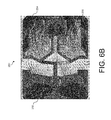
- FIG. 6B illustrates an example of air flow resulting from the multi-step lubricant barrier configuration of FIG. 6A .
- magnetic storage devices such as HDDs use magnetic media to store data and a movable slider having magnetic transducers positioned over the magnetic media to selectively read data from and write data to the magnetic media.
- the movable slider and magnetic transducers may be a sub-component of a head gimbal assembly (HGA).
- a magnetic transducer typically comprises a magneto-resistive read element (e.g., a so-called giant magneto-resistive read element, or a tunneling magneto-resistive read element) and an inductive write structure comprising a flat coil deposited by photolithography and a yoke structure having pole tips that face a disk media.
- FIGS. 1A and 1B illustrate an example magnetic disk drive 10 that can include a sealed enclosure 12 , a disk drive motor 14 , a magnetic disk 16 , supported for rotation by a spindle S 1 of motor 14 , an actuator 18 and an arm 20 attached to a spindle S 2 of actuator 18 .
- Suspension 22 is coupled at one end to arm 20 , and at its other end to a read/write head or transducer 24 .
- Transducer 24 typically includes an inductive write element with a magneto-resistive read element (shown in FIG. 1C ).
- an air bearing is formed between an air bearing surface (ABS) of transducer 24 and a surface of magnetic disk 16 causing transducer 24 to lift slightly off of the surface of magnetic disk 16 , or, as it is termed in the art, to “fly” above magnetic disk 16 .
- ABS air bearing surface
- Various magnetic “tracks” of information can be read from magnetic disk 16 as actuator 18 causes transducer 24 to pivot in a short arc as indicated by arrows P.
- FIG. 1C illustrates a magnetic read/write head 30 including a write element 32 and read element 34 .
- the edges of write element 32 and read element 34 also define an ABS in a plane which flies above the surface of the magnetic disk 16 during operation.
- Read element 34 includes a first shield 44 , an intermediate layer 38 which serves as a second shield, and a read sensor 46 located between the first shield 44 and the intermediate layer 38 .
- Read sensor 46 has a particular stripe height and a particular location between the first shield 44 and the second shield 38 , both of which are chosen to attain a particular read performance. Control of stripe height is important in controlling device resistance, device output amplitude, device bias point and consequently many related measures of performance. Magneto-resistive sensors can be used with a variety of stripe heights, with a typical stripe height being smaller than about 2 microns, including much less than 1 micron. Further, although read sensor 46 is shown in FIG. 1C as a shielded single-element vertical read sensor, read element 34 can take a variety of forms as is known to those skilled in the art, such as unshielded read sensors.
- Write element 32 is typically an inductive write element including the intermediate layer 38 which serves as a first yoke element or pole, and a second yoke element or pole 36 , defining a write gap 40 therebetween.
- First yoke element 38 and second yoke element 36 are configured and arranged relative to each other such that the write gap 40 has a particular nose length, NL.
- a conductive coil 42 that is positioned within a dielectric medium 43 . As is well known to those skilled in the art, these elements operate to magnetically write data on a magnetic medium such as a magnetic disk 16 .
- the flying height (FH) which can refer to the aforementioned air bearing space between media (e.g., magnetic disk 16 ) and the magnetic read/write head 30 (of a transducer) on a slider, is a key parameter that affects the performance of a magnetic storage device. Accordingly, a nominal FH is typically chosen to be a careful compromise between extremes in a classic engineering “trade-off”. Decreasing the FH is advantageous because an FH that is too high degrades the ability of the transducer to write and/or read information to/from the surface of the media/disk surface. Therefore, reductions in FH can facilitate desirable increases in the areal density of data stored on a disk surface. However, the air bearing between the slider and the disk surface cannot be eliminated entirely because the air bearing serves to reduce friction and wear (between the slider and the disk surface) to an acceptable level.
- the air bearing between the media and magnetic read/write head is quite thin and therefore, very susceptible to unwanted effects resulting from the introduction of any type of contaminate, such as particulate matter/particles and lubricant (lube) droplets or particles that can become trapped in the air bearing.
- a magnetic read/write head can be mounted on a slider that flies a mere 10 nm (an approximate example) over the media. Any particulate matter that accumulates by being trapped within this very thin air bearing can create a variety of problems including, but not limited to the following: abrasive wear on the media/disk surface; magnetic spacing modulation; unstable flying conditions; and in extreme cases, crashing of the slider onto the media/disk surface.
- one challenge that disk drive engineers face involves removing or preventing the entry of any particulate matter that is introduced into the air bearing so as to constantly maintain the desired nominal FH and reduce the risk of any particle-caused failures.
- Certain methods that have been developed in an attempt to reduce contamination in the air bearing have been directed at “blocking” particles from entering the air bearing, such as using a fence at a leading edge of the slider to block particles from entering the air bearing.
- Other methods include a particle trap design using deep pits in the leading area of the slider to trap particles that have already entered the air bearing.
- Still other methods rely on a lube blocker design, where a fence blocks lubricant droplets from entering the air bearing from the trailing edge of the slider.
- the aforementioned methods can have a negative impact on the performance of the HDD due to incoming air flow that can also be blocked or trapped using such structures. That is, the aforementioned conventional methods of particle/droplet contamination prevention introduce air flow stagnation in one or more etched cavities within the slider. It is within these cavities that particles and droplets often accumulate. Therefore, stagnant air flow (or the lack of air flow) in these areas can exacerbate or even cause these contaminant accumulation problems.
- various embodiments of the present disclosure are directed to one or more structural ABS features that can block particulate matter, such as lube droplets that may enter the air bearing from the trailing edge or rearward portion of the slider.
- structural ABS features can influence air flow within or about the air bearing to prevent or at least reduce the accumulation of particles and/or droplets in one or more areas of the air bearing to reduce the reliability problems induced by particle contamination and lube pick-up.
- one or more cavities are etched in the rear portion of the slider, close to the central pad of the slider.
- FIG. 2A is a bottom view of an example slider 200 configured with a conventional lube blocker structure.
- Slider 200 may have a leading edge 202 and a trailing edge 204 .
- the bottom surface of slider 200 makes up an ABS, where the various shaded areas of the bottom surface of slider 200 are indicative of areas that have been etched at various depths resulting in different cavities, steps, and/or pads, one of which is cavity 208 (which can be etched to a depth of 1 ⁇ m relative to the ABS of slider 200 ).
- a conventional lube blocker 206 is implemented to block, e.g., lube droplets from entering the air bearing from rear or trailing edge 204 of slider 200 .
- Conventional lube blocker 206 may have a depth of 0.2 ⁇ m. It should be noted that depth measurements provided herein refer to depth, e.g., of a cavity or other etched surface or area relative to the lowest surface of the slider. As would be understood by those of ordinary skill in the art, the lowest surface of a slider that flies over a recording medium is that which is nearest the recording medium. In other words, FIG. 2A (in addition to other representations of a slider) illustrates bottom views that are upside down.
- FIG. 2B illustrates air flow patterns within or about the ABS of slider 200 .
- lube blocker 206 may have the ability to block some amount of lube droplets from entering cavity 208 .
- air flow becomes stagnant in cavity 208 (proximate to lube blocker 206 ) resulting in the accumulation of any lube droplets or particulate matter in cavity 208 .
- the blocking 100% of particles and/or droplets from entering the air bearing of a slider is near impossible, if not entirely impossible. Accordingly, some particles and/or droplets will find their way to the air bearing of slider 200 . Without airflow in those areas where particles and/or droplets accumulate, such as cavity 208 , the particles and/or droplets will remain and can result in one or more of the aforementioned issues.
- multi-step lube blocking structures can provide a “stepped” progression (with one or more steps or ledges) from a lube blocker structure into a cavity area proximate to the trailing edge of a slider.
- the number of steps or ledges may vary in accordance with different embodiments, but the number of steps or ledges may generally be a function of the depth of the cavity in which they are implemented. That is, the deeper the cavity, the more steps or ledges may be needed to maintain air movement in the cavity. For example, a cavity depth of approximately 2 ⁇ m or less may correspond to the use of a maximum of three steps.
- the change in depth between adjacent steps or ledges is generally smaller than approximately 0.5 ⁇ m.
- the width of such steps or ledges may be approximately 15-40 ⁇ m, and in some applications, smaller steps or ledges may be preferable, while still remaining within any manufacturing thresholds.
- sliders may have varying dimensions.
- a “Pemto” type slider design may generally refer to a slider having the following dimensions: approximately 1.25 mm long, approximately 0.7 mm wide, and approximately 0.23 mm thick, although some manufacturers due to particular manufacturing requirements may configure a Pemto type slider to be, e.g., approximately 1.35 mm long.
- a “Femto” type slider may generally refer to a slider having the following dimensions: approximately 0.85 mm long, approximately 0.7 mm wide, and approximately 0.23 mm thick.
- slider 200 may be a Pemto type ABS slider design, where the length of slider 200 is approximately 1.253 mm, the width is approximately 0.7 mm, and the thickness at its largest (shallowest etched area(s)) is approximately 0.23 mm.
- slider 200 may be a Femto type ABS slider design, where one or more dimensions of slider 200 and/or one or more elements of slider 200 may be decreased.
- the length of a Femto type ABS slider configured in accordance with another example may be about 0.85 mm
- the width may be about 0.7 mm
- the thickness at its largest (shallowest etched area(s)) may be about 0.23 mm.
- FIGS. 3A and 3B illustrate an example of a multi-step lube blocking structure and air flow patterns, respectively, in the air bearing of slider 200 .
- FIG. 3A illustrates slider 200 having a leading edge 202 and trailing edge 204 .
- Slider 200 may be configured with an etched cavity 208 .
- Proximate to trailing edge 204 is a lube blocker structure 206 .
- a step 210 may be etched substantially proximate to or abutting a side of lube blocker structure 206 on the side of cavity 208 .
- cavity 208 may have a depth of approximately 1 ⁇ m
- lube blocker structure 206 may have a depth of 0.2 ⁇ m
- step 210 may be etched to a depth of 0.55 ⁇ m.
- FIG. 3B illustrates air flow patterns in the ABS of slider 200 . It can be appreciated that with the introduction of step 210 , airflow is no longer stagnant in cavity 208 . Rather, it can be appreciated that any particles or lube droplets that may reach the air bearing of slider 200 will be flushed away from or out of cavity 208 .
- FIGS. 4A and 4B illustrate an example of a multi-step lube blocking structure and airflow patterns, respectively, in the air bearing of slider 200 .
- FIG. 4A again illustrates slider 200 having a leading edge 202 and trailing edge 204 .
- Slider 200 may be configured with an etched cavity 208 .
- Proximate to trailing edge 204 is a lube blocker structure 206 .
- a step 210 may be etched substantially proximate to or abutting a side of lube blocker structure 206 on the side of cavity 208 .
- cavity 208 may have a depth of approximately 1.5 ⁇ m
- lube blocker structure 206 may have a depth of 0.2 ⁇ m
- step 210 may be etched to a depth of 0.55 ⁇ m.
- FIG. 4B illustrates air flow patterns in the ABS of slider 200 . It can be appreciated that with the introduction of step 210 , stagnation in airflow is improved compared to that experienced using a conventional lube blocker structure without any steps/ledges. However, some amount of stagnation reappears in cavity 208 due to the increase in depth of cavity 208 .
- FIGS. 5A and 5B illustrate another multi-step lube blocking structure and airflow patterns, respectively that can be applied to sliders having deeper cavities, such as that illustrated in FIGS. 4A and 4B .
- slider 200 has a leading edge 202 and trailing edge 204 .
- Slider 200 may be configured with an etched cavity 208 .
- Proximate to trailing edge 204 is a lube blocker structure 206 .
- a first step 210 may be etched substantially proximate to or abutting a side of lube blocker structure 206 on the side of cavity 208 .
- Still another second step 212 can be etched substantially proximate to or abutting a side of first step 210 on the side of cavity 208 . Accordingly, from trailing edge 204 , there is a stepped structure including lube blocker structure 206 , first step 210 , and second step 212 leading to cavity 208 .
- cavity 208 may have a depth of approximately 1.5 ⁇ m
- lube blocker structure 206 may have a depth of approximately 0.2 ⁇ m
- first step 210 may be etched to a depth of approximately 0.55 ⁇ m
- second step 212 may be etched to a depth of approximately 1.0 ⁇ m.
- FIG. 5B illustrates air flow patterns in the ABS of slider 200 . It can be appreciated that airflow is further improved within or about the ABS at cavity 208 . That is, a first side of cavity 208 shows no stagnation of airflow, while a second side of cavity 208 shows only minimal stagnation of airflow at second step 212 .
- FIGS. 6A and 6B illustrate still another multi-step lube blocking structure and airflow patterns, respectively that can be applied to sliders having deeper cavities, such as that illustrated in FIGS. 4A and 4B .
- slider 200 has a leading edge 202 and trailing edge 204 .
- Slider 200 may be configured with an etched cavity 208 .
- Proximate to trailing edge 204 is a lube blocker structure 206 .
- a first step 210 may be etched substantially proximate to or abutting a side of lube blocker structure 206 on the side of cavity 208 .
- a second step 212 can be etched substantially proximate to or abutting a side of first step 210 on the side of cavity 208 .
- a third step 214 can be etched substantially proximate to or abutting a side of second step 212 on the side of cavity 208 .
- cavity 208 may have a depth of approximately 1.5 ⁇ m
- lube blocker structure 206 may have a depth of approximately 0.2 ⁇ m
- first step 210 may be etched to a depth of approximately 0.5 ⁇ m
- second step 212 may be etched to a depth of approximately 0.8 ⁇ m
- third step 214 may be etched to a depth of approximately 1.15 ⁇ m.
- FIG. 6B illustrates air flow patterns in the ABS of slider 200 . It can be appreciated that airflow is improved yet again within or about the ABS at cavity 208 , where airflow stagnation is substantially eliminated in cavity 208 . Thus, that any particles or lube droplets that may reach the air bearing of slider 200 will be flushed away from or out of cavity 208 .
- Various embodiments provide an easy and convenient mechanism that allows ABS designers to avoid the problems associated with particle and/or lubricant contamination.
- various multi-step lube blocking structures can be implemented on a slider to not only reduce the introduction of particulate matter/droplets into the air bearing, but also promote airflow in areas where particulate matter/droplets that are not prevented from entering the air bearing can still be flushed away.
- ABS features eliminate or at least reduce the opportunity for particles and lubricant to interact with the ABS, that chance for failure of the HDD and/or damage caused by the particles and/or lubricant is also eliminated or at least reduced.
- various embodiments disclosed herein have been described in the context of magnetic recording media, various embodiments can be adapted for use with other forms of media, e.g., magneto-optical disks, optical disks, etc.
- the terms “over,” “under,” “between,” and “on” as used herein refer to a relative position of one media layer with respect to other layers.
- one layer disposed over or under another layer may be directly in contact with the other layer or may have one or more intervening layers.
- one layer disposed between two layers may be directly in contact with the two layers or may have one or more intervening layers.
- a first layer “on” a second layer is in contact with that second layer.
- the relative position of one layer with respect to other layers is provided assuming operations are performed relative to a substrate without consideration of the absolute orientation of the substrate.
- module does not imply that the components or functionality described or claimed as part of the module are all configured in a common package. Indeed, any or all of the various components of a module, whether control logic or other components, can be combined in a single package or separately maintained and can further be distributed in multiple groupings or packages or across multiple locations.
Abstract
Description
Claims (20)
Priority Applications (1)
| Application Number | Priority Date | Filing Date | Title |
|---|---|---|---|
| US14/583,017 US9190090B1 (en) | 2014-12-24 | 2014-12-24 | Multi step lube blocking air bearing area configuration |
Applications Claiming Priority (1)
| Application Number | Priority Date | Filing Date | Title |
|---|---|---|---|
| US14/583,017 US9190090B1 (en) | 2014-12-24 | 2014-12-24 | Multi step lube blocking air bearing area configuration |
Publications (1)
| Publication Number | Publication Date |
|---|---|
| US9190090B1 true US9190090B1 (en) | 2015-11-17 |
Family
ID=54434661
Family Applications (1)
| Application Number | Title | Priority Date | Filing Date |
|---|---|---|---|
| US14/583,017 Active US9190090B1 (en) | 2014-12-24 | 2014-12-24 | Multi step lube blocking air bearing area configuration |
Country Status (1)
| Country | Link |
|---|---|
| US (1) | US9190090B1 (en) |
Cited By (5)
| Publication number | Priority date | Publication date | Assignee | Title |
|---|---|---|---|---|
| US10249334B1 (en) | 2018-02-28 | 2019-04-02 | Western Digital Technologies, Inc. | Slider air-bearing surface designs with side particle-trapping structures |
| US10354685B1 (en) | 2018-02-28 | 2019-07-16 | Western Digital Technologies, Inc. | Slider air-bearing surface designs with segmented particle-trapping structures |
| US11232812B1 (en) | 2021-02-18 | 2022-01-25 | Sae Magnetics (H.K.) Ltd. | Air-bearing surface (ABS) design with side flow blocker for mitigating lube and hydrocarbon accumulation in hard disk drives (HDD) |
| CN114730573A (en) * | 2020-06-26 | 2022-07-08 | 西部数据技术公司 | Slider with low aspect ratio |
| US11942124B1 (en) | 2022-10-24 | 2024-03-26 | Western Digital Technologies, Inc. | Slider air bearing designs with side blocker for contamination robustness |
Citations (136)
| Publication number | Priority date | Publication date | Assignee | Title |
|---|---|---|---|---|
| US5490025A (en) | 1994-12-08 | 1996-02-06 | International Business Machines Corporation | Air bearing slider with debris deflecting features |
| US5940249A (en) | 1997-11-10 | 1999-08-17 | International Business Machines Corporation | Shielded air bearing slider |
| US6075673A (en) | 1997-05-05 | 2000-06-13 | Read-Rite Corporation | Composite slider design |
| US6097575A (en) | 1998-07-14 | 2000-08-01 | Read-Rite Corporation | Composite slider with housing and interlocked body |
| US6125015A (en) | 1998-12-04 | 2000-09-26 | Read-Rite Corporation | Head gimbal assembly with low stiffness flex circuit and ESD Protection |
| US6125014A (en) | 1998-06-26 | 2000-09-26 | Read-Rite Corporation | Via-less connection using interconnect traces between bond pads and a transducer coil of a magnetic head slider |
| US6130863A (en) | 1997-11-06 | 2000-10-10 | Read-Rite Corporation | Slider and electro-magnetic coil assembly |
| US6137656A (en) | 1998-10-26 | 2000-10-24 | Read-Rite Corporation | Air bearing slider |
| US6144528A (en) | 1998-10-26 | 2000-11-07 | Read-Rite Corporation | Air bearing slider with reduced stiction |
| US6147838A (en) | 1997-02-10 | 2000-11-14 | Read-Rite Corporation | Air bearing slider with shaped taper |
| US6151196A (en) | 1999-02-16 | 2000-11-21 | Read-Rite Corporation | Magnetic head suspension assembly including an intermediate flexible member that supports an air bearing slider with a magnetic transducer for testing |
| US6181673B1 (en) | 1996-07-30 | 2001-01-30 | Read-Rite Corporation | Slider design |
| US6181522B1 (en) | 1998-12-12 | 2001-01-30 | Read-Write Corporation | Read/write head with a gimbal ball assembly |
| US6229672B1 (en) | 1998-10-19 | 2001-05-08 | Read-Rite Corporation | High gram load air bearing geometry for a tripad slider |
| US6236543B1 (en) | 1999-01-29 | 2001-05-22 | Read-Rite Corporation | Durable landing pads for an air-bearing slider |
| US6246547B1 (en) | 1999-02-16 | 2001-06-12 | Read-Rite Corporation | Low profile flexure and slider-flexure assembly |
| US6249404B1 (en) | 1999-02-04 | 2001-06-19 | Read-Rite Corporation | Head gimbal assembly with a flexible printed circuit having a serpentine substrate |
| US6330131B1 (en) | 1993-09-17 | 2001-12-11 | Read-Rite Corporation | Reduced stiction air bearing slider |
| US6349017B1 (en) | 1997-02-21 | 2002-02-19 | Read-Rite Corporation | Magnetic head suspension assembly using bonding pads of a slider to an attachment surface of a flexure |
| US6373660B1 (en) | 2000-03-14 | 2002-04-16 | Read-Rite Corporation | Method and system for providing a permanent shunt for a head gimbal assembly |
| US6522504B1 (en) | 2001-01-31 | 2003-02-18 | Western Digital Technologies, Inc. | Head stack assembly and disk drive using a reversed direction head gimbal assembly |
| US6538850B1 (en) | 1999-10-06 | 2003-03-25 | Read-Rite Corporation | Low profile head gimbal assembly with shock limiting and load/unload capability and method of manufacture thereof |
| US20030058578A1 (en) | 2001-09-27 | 2003-03-27 | Zine-Eddine Boutaghou | Disc head slider designs with particle flushing channels |
| US6583953B1 (en) | 1999-07-12 | 2003-06-24 | Mark Lauer | Silicon carbide overcoats for information storage systems and method of making |
| US6594113B2 (en) | 2000-12-20 | 2003-07-15 | Seagate Technology Llc | Slider with furrows for flushing contaminants and lubricant |
| US20030165031A1 (en) | 2002-02-15 | 2003-09-04 | Rajashankar Rajakumar | AAB slider with improved particle sensitivity |
| US6646832B2 (en) | 2001-01-29 | 2003-11-11 | Manuel Anaya-Dufresne | Slider for load/unload operation with high stiffness and low unload force |
| US6661612B1 (en) | 2001-10-21 | 2003-12-09 | Western Digital Technologies, Inc. | Air bearing slider including side rail shallow recessed surfaces extending along trailing portions of leading side air bearing surfaces |
| US6665146B2 (en) | 1999-12-28 | 2003-12-16 | Western Digital (Fremont) | Airflow assisted ramp loading and unloading of sliders in hard disk drives |
| US20040012887A1 (en) | 2002-07-17 | 2004-01-22 | Rajashankar Rajakumar | Head slider having convergent channel features with side opening |
| US6690545B1 (en) | 2001-09-28 | 2004-02-10 | Western Digital Technologies, Inc. | Air bearing slider including a depressed region extending from a main support structure between a pressurized pad support base and a contact pad support base |
| US20040027724A1 (en) | 2002-08-06 | 2004-02-12 | Pendray John R. | Disc head slider with bearing pad design |
| US6704173B1 (en) | 2000-08-16 | 2004-03-09 | Western Digital (Fremont), Inc. | Method and system for providing ESD protection using diodes and a grounding strip in a head gimbal assembly |
| US6721142B1 (en) | 2000-12-21 | 2004-04-13 | Western Digital (Fremont) Inc. | Non-corrosive GMR slider for proximity recording |
| US6744599B1 (en) | 2002-04-30 | 2004-06-01 | Western Digital Technologies, Inc. | Air bearing slider with an angularly disposed channel formed between a side rail and a leading side air bearing surface |
| US6771468B1 (en) | 2001-10-22 | 2004-08-03 | Western Digital Corporation | Slider with high pitch-stiffness air bearing design |
| US20040150916A1 (en) | 2000-04-12 | 2004-08-05 | Seagate Technology Llc | Slider with recessed pressurization surfaces |
| US20040156143A1 (en) | 2003-02-08 | 2004-08-12 | Samsung Electronics Co., Ltd. | Air bearing slider for disk drive |
| US6796018B1 (en) | 2001-12-21 | 2004-09-28 | Western Digital (Fremont), Inc. | Method of forming a slider/suspension assembly |
| US6801402B1 (en) | 2002-10-31 | 2004-10-05 | Western Digital Technologies, Inc. | ESD-protected head gimbal assembly for use in a disk drive |
| US6873496B1 (en) | 2000-01-03 | 2005-03-29 | Western Digital Fremont, Inc. | Side rail slider having improved fly height control |
| US6879464B2 (en) | 2002-08-16 | 2005-04-12 | Western Digital (Fremont), Inc. | Air bearing having a cavity patch surface coplanar with a leading edge pad surface |
| US20050105216A1 (en) | 2003-10-21 | 2005-05-19 | Matsushita Electric Industrial Co., Ltd. | Head slider and disk drive with the same |
| US6912103B1 (en) | 2002-07-31 | 2005-06-28 | Western Digital Technologies, Inc. | Method of operating a disk drive with a slider at loading and unloading fly heights greater than an operational fly height |
| US6920015B2 (en) | 2001-04-03 | 2005-07-19 | Seagate Technology Llc | Disc head slider designs to reduce particle sensitivity |
| US6937439B1 (en) | 2001-11-30 | 2005-08-30 | Western Digital Technologies, Inc. | Slider having a textured air bearing surface, head stack assembly and disk drive using same |
| US6956718B1 (en) | 2002-08-19 | 2005-10-18 | Western Digital (Fremont), Inc. | Sandwich diamond-like carbon overcoat for use in slider designs of proximity recording heads |
| US6972930B1 (en) | 2003-02-28 | 2005-12-06 | Western Digital Technologies, Inc. | ESD-protected slider and head gimbal assembly |
| US6980399B2 (en) | 2003-10-15 | 2005-12-27 | Seagate Technology Llc | Air bearing sliders with a pressure cavity or cavities |
| US7006331B1 (en) | 2003-09-30 | 2006-02-28 | Western Digital Technologies, Inc. | Head gimbal assembly including a trace suspension assembly backing layer with a conductive layer formed upon a gimbal having a lower oxidation rate |
| US7006330B1 (en) | 2003-03-10 | 2006-02-28 | Western Digital Technologies, Inc. | Head stack assembly including a ground conductive pad for grounding a slider to a gimbal |
| USRE39004E1 (en) | 1997-08-22 | 2006-03-07 | Samsung Electronics Co., Ltd. | Pseudo contact type negative pressure air bearing slider |
| US7019945B1 (en) | 2002-12-23 | 2006-03-28 | Western Digital Technologies, Inc. | Air bearing slider including pressurized side pads with forward and trailing shallow etched surfaces |
| US7027264B1 (en) | 2003-10-31 | 2006-04-11 | Western Digital Technologies, Inc. | Slider with a slider ground pad electrically connected to write head poles and read head shields |
| US7085104B1 (en) | 1999-10-06 | 2006-08-01 | Western Digital (Fremont), Inc. | Low profile head gimbal assembly with shock limiting and load/unload capability |
| US7099117B1 (en) | 2003-09-30 | 2006-08-29 | Western Digital Technologies, Inc. | Head stack assembly including a trace suspension assembly backing layer and a ground trace for grounding a slider |
| US20070103816A1 (en) | 2003-07-23 | 2007-05-10 | Matsushita Electric Industrial Co., Ltd. | Slider and magnetic disk device using the slider |
| US7230797B1 (en) | 2004-10-08 | 2007-06-12 | Seagate Technology, Llc | Slider having transversely separated bearing surfaces and openings to rear bearing surfaces |
| US7256965B2 (en) | 2003-04-10 | 2007-08-14 | Seagate Technology Llc | Adaptable air bearing slider with trailing edge cavity |
| US20070195461A1 (en) | 2006-02-17 | 2007-08-23 | Fujitsu Limited | Head apparatus and disc drive having the same |
| US7289299B1 (en) | 2005-02-02 | 2007-10-30 | Western Digital (Fremont), Llc | Air bearing slider with three-projection trailing center pad |
| US7307816B1 (en) | 2001-12-21 | 2007-12-11 | Western Digital (Fremont), Llc | Flexure design and assembly process for attachment of slider using solder and laser reflow |
| US7315436B1 (en) | 2004-06-25 | 2008-01-01 | Western Digital Technologies, Inc. | Suspension assembly with a shape memory actuator coupled to a gimbal |
| US7315435B1 (en) | 2005-03-17 | 2008-01-01 | Western Digital Technologies, Inc. | Disk drives, head stack, head gimbal and suspension assemblies having positional conductive features |
| US7408742B2 (en) | 2003-07-03 | 2008-08-05 | Fujitsu Limited | Magnetic head slider and method of fabricating magnetic head slider |
| US7414814B1 (en) | 2005-04-28 | 2008-08-19 | Western Digital Technologies, Inc. | Disk drives, head stack, head gimbal and suspension assemblies having a compliant suspension tail design for solder reflow |
| US7436631B1 (en) | 2004-06-30 | 2008-10-14 | Western Digital (Fremont), Llc | Heated gimbal for magnetic head to disk clearance adjustment |
| US7474508B1 (en) | 2005-03-09 | 2009-01-06 | Western Digital (Fremont), Inc. | Head gimbal assembly with air bearing slider crown having reduced temperature sensitivity |
| US7477486B1 (en) | 2005-12-07 | 2009-01-13 | Western Digital (Fremont), Llc | Air bearing slider with a side pad having a shallow recess depth |
| US7525763B2 (en) | 2005-07-27 | 2009-04-28 | Sae Magnetics (H.K.) Ltd. | Head gimbal assembly with particle filter device, and disk drive unit with the same |
| US7595963B1 (en) | 2006-06-07 | 2009-09-29 | Western Digital Technologies, Inc. | Head gimbal assembly including a flexure with a first conductive trace disposed between a slider and a dielectric layer |
| US7616405B2 (en) | 2006-11-15 | 2009-11-10 | Western Digital (Fremont), Llc | Slider with an air bearing surface having a inter-cavity dam with OD and ID dam surfaces of different heights |
| US7729089B1 (en) | 2006-10-13 | 2010-06-01 | Western Digital Technologies, Inc. | Head-gimbal assembly including a flexure tongue with stand-offs arranged to facilitate lateral light entry |
| US7916426B2 (en) | 2007-11-30 | 2011-03-29 | Western Digital (Fremont), Llc | Head with an air bearing surface having left and right leading pressurizing steps, each with short and long regions |
| US7978435B2 (en) | 2006-12-13 | 2011-07-12 | Kabushiki Kaisha Toshiba | Magnetic head slider having multiple step portions |
| US7995310B1 (en) | 2006-11-09 | 2011-08-09 | Western Digital Technologies, Inc. | Head-gimbal assembly including a flexure tongue with adhesive receptacles disposed adjacent to stand-offs |
| US20110195275A1 (en) | 2010-02-05 | 2011-08-11 | Seagate Technology Llc | Material deposition on transducing head |
| US8081400B1 (en) | 2008-08-29 | 2011-12-20 | Western Digital (Fremont), Llc | Slider with an air-bearing surface including four pressure generating pockets for countering disruptive movement |
| US8089730B1 (en) | 2009-10-28 | 2012-01-03 | Western Digital (Fremont), Llc | Suspension assembly having a read head clamp |
| US8087973B1 (en) | 2008-08-19 | 2012-01-03 | Western Digital (Fremont), Llc | Slider with leading edge blend and conformal step features |
| US8094411B2 (en) | 2008-10-14 | 2012-01-10 | Hitachi Global Storage Technologies Netherlands B.V. | Slider with pockets in front of air bearing surface |
| US8116037B2 (en) * | 2008-12-09 | 2012-02-14 | Hitachi Global Storage Technologies, Netherlands B.V. | Disk drive including head-slider configured to suppress lubricant droplet accumulation |
| US8164858B1 (en) | 2009-11-04 | 2012-04-24 | Western Digital (Fremont), Llc | Read head having conductive filler in insulated hole through substrate |
| US8184405B1 (en) * | 2011-01-14 | 2012-05-22 | Sae Magnetics (Hk) Ltd. | Air-bearing slider design for sub-nanometer clearance in hard disk drive (HDD) |
| US8199437B1 (en) | 2010-03-09 | 2012-06-12 | Western Digital (Fremont), Llc | Head with an air bearing surface having a particle fence separated from a leading pad by a continuous moat |
| US8208224B1 (en) | 2011-08-29 | 2012-06-26 | Western Digital Technologies, Inc. | Suspension assemblies for minimizing stress on slider solder joints |
| US8218268B1 (en) | 2009-05-27 | 2012-07-10 | Western Digital Technologies, Inc. | Head gimbal assembly having a load beam aperature over conductive heating pads that are offset from head bonding pads |
| US8240545B1 (en) | 2011-08-11 | 2012-08-14 | Western Digital (Fremont), Llc | Methods for minimizing component shift during soldering |
| US8256272B1 (en) | 2009-12-23 | 2012-09-04 | Western Digital (Fremont), Llc | UV adhesive viscosity adjustment apparatus and method |
| US8289653B2 (en) * | 2010-02-17 | 2012-10-16 | Hitachi Global Storage Technologies Netherlands B.V. | ABS with a lubrication control dam for hard disk drives |
| US8295014B1 (en) | 2010-10-29 | 2012-10-23 | Western Digital Technologies, Inc. | Disk drive head gimbal assembly having a flexure tail with transverse flying leads |
| US8295013B1 (en) | 2010-10-29 | 2012-10-23 | Western Digital Technologies, Inc. | Disk drive head stack assembly having a flexible printed circuit with heat transfer limiting features |
| US8295012B1 (en) | 2011-06-14 | 2012-10-23 | Western Digital Technologies, Inc. | Disk drive suspension assembly with rotary fine actuator at flexure tongue |
| US8320084B1 (en) | 2010-10-29 | 2012-11-27 | Western Digital Technologies, Inc. | Disk drive head gimbal assembly having a flexure tail with features to facilitate bonding |
| US8325446B1 (en) | 2010-10-29 | 2012-12-04 | Western Digital Technologies, Inc. | Disk drive head gimbal assembly having a flexure tail with features to facilitate bonding |
| US8339748B2 (en) | 2010-06-29 | 2012-12-25 | Western Digital Technologies, Inc. | Suspension assembly having a microactuator bonded to a flexure |
| US8339747B1 (en) | 2011-03-11 | 2012-12-25 | Western Digital Technologies, Inc. | Removable actuator assemblies for testing head gimbal assemblies of a storage device |
| US8343363B1 (en) | 2010-03-10 | 2013-01-01 | Western Digital (Fremont), Llc | Method and system for fabricating a cavity in a substrate of a magnetic recording head |
| US8345519B1 (en) | 2010-12-22 | 2013-01-01 | Western Digital (Fremont), Llc | Method and system for providing a suspension head bond pad design |
| US8418353B1 (en) | 2009-12-23 | 2013-04-16 | Western Digital (Fremont), Llc | Method for providing a plurality of energy assisted magnetic recording EAMR heads |
| US8441896B2 (en) | 2010-06-25 | 2013-05-14 | Western Digital (Fremont), Llc | Energy assisted magnetic recording head having laser integrated mounted to slider |
| US8446694B1 (en) | 2011-06-14 | 2013-05-21 | Western Digital Technologies, Inc. | Disk drive head suspension assembly with embedded in-plane actuator at flexure tongue |
| US8456776B1 (en) | 2010-09-22 | 2013-06-04 | Western Digital Technologies, Inc. | Disk drive head gimbal assembly having a flexure bond pad shelf offset from a tongue |
| US8456643B2 (en) | 2010-05-24 | 2013-06-04 | Western Digital (Fremont), Llc | Method and system for mapping the shape of a head under operating conditions |
| US8462462B1 (en) | 2011-10-20 | 2013-06-11 | Western Digital (Fremont), Llc | Localized heating for flip chip bonding |
| US8477459B1 (en) | 2010-10-29 | 2013-07-02 | Western Digital Technologies, Inc. | Disk drive head gimbal assembly having a flexure tail with dual conductive layers and features to facilitate bonding |
| US8490211B1 (en) | 2012-06-28 | 2013-07-16 | Western Digital Technologies, Inc. | Methods for referencing related magnetic head microscopy scans to reduce processing requirements for high resolution imaging |
| US8485579B2 (en) | 2011-03-17 | 2013-07-16 | Western Digital (Fremont), Llc | Vacuum pickup assemblies for picking up articles and minimizing contamination thereof |
| US8488281B1 (en) | 2011-09-13 | 2013-07-16 | Western Digital (Fremont), Llc | Disk drive suspension assembly having a flexure bond pad shelf separate from a tongue |
| US8488279B1 (en) | 2011-11-22 | 2013-07-16 | Western Digital (Fremont), Llc | Disk drive suspension assembly with flexure having stacked interleaved traces |
| US8514522B1 (en) | 2011-01-25 | 2013-08-20 | Western Digital (Fremont), Llc | Systems for interconnecting magnetic heads of storage devices in a test assembly |
| US8533936B1 (en) | 2011-01-26 | 2013-09-17 | Western Digital (Fremont), Llc | Systems and methods for pre-heating adjacent bond pads for soldering |
| US20130244541A1 (en) | 2012-03-14 | 2013-09-19 | Western Digital Technologies, Inc. | Systems and methods for correcting slider parallelism error using compensation lapping |
| US8545164B2 (en) | 2010-12-06 | 2013-10-01 | Western Digital (Fremont), Llc | Systems and methods for repositioning row bars used for manufacturing magnetic heads |
| US8553365B1 (en) | 2012-02-21 | 2013-10-08 | Western Digital (Fremont), Llc | Apparatuses and methods for loading a head onto a disk medium |
| US20130293982A1 (en) | 2012-05-02 | 2013-11-07 | Western Digital Technologies, Inc. | Disk drive employing single polarity supply voltage to generate write current |
| US8587901B1 (en) | 2009-12-30 | 2013-11-19 | Western Digital (Fremont), Llc | Magnetic recording head slider comprising bond pad having a probe contact area and a solder contact area |
| US8593764B1 (en) | 2011-06-14 | 2013-11-26 | Western Digital Technologies, Inc. | Method for fine actuation of a head during operation of a disk drive |
| US8599653B1 (en) | 2012-09-11 | 2013-12-03 | Western Digital Technologies, Inc. | Systems and methods for reducing condensation along a slider air bearing surface in energy assisted magnetic recording |
| US8605389B1 (en) | 2006-06-09 | 2013-12-10 | Western Digital Technologies, Inc. | Head gimbal assembly including a conductive trace disposed upon a continuous dielectric layer segment without overlying a gimbal arm |
| US8611052B1 (en) | 2012-03-27 | 2013-12-17 | Western Digital Technologies, Inc. | Systems and methods for aligning components of a head stack assembly of a hard disk drive |
| US8611051B1 (en) | 2013-02-25 | 2013-12-17 | Kabushiki Kaisha Toshiba | Magnetic head, head gimbal assembly with the same, and disk drive |
| US8624184B1 (en) | 2012-11-28 | 2014-01-07 | Western Digital Technologies, Inc. | Methods for spatially resolved alignment of independent spectroscopic data from scanning transmission electron microscopes |
| US8623197B1 (en) | 2010-12-20 | 2014-01-07 | Western Digital (Fremont), Llc | Testing workpiece overcoat |
| US8665567B2 (en) | 2010-06-30 | 2014-03-04 | Western Digital Technologies, Inc. | Suspension assembly having a microactuator grounded to a flexure |
| US8665677B1 (en) | 2011-12-19 | 2014-03-04 | Western Digital (Fremont), Llc | Disk drive magnetic read head with affixed and recessed laser device |
| US8665566B1 (en) | 2011-12-20 | 2014-03-04 | Western Digital Technologies, Inc. | Suspension tail design for a head gimbal assembly of a hard disk drive |
| US8693144B1 (en) | 2013-03-15 | 2014-04-08 | Western Digital Technologies, Inc. | Head gimbal assemblies and methods for measuring slider parameters |
| US8758083B1 (en) | 2010-09-13 | 2014-06-24 | Western Digital (Fremont), Llc | Method and system for adjusting lapping of a transducer using a disk windage |
| US8760812B1 (en) | 2011-12-20 | 2014-06-24 | Western Digital Technologies, Inc. | Disk drive head gimbal assembly having a jumper in a flexible printed circuit overlap region |
| US8770463B1 (en) | 2013-05-20 | 2014-07-08 | Western Digital Technologies, Inc. | Head gimbal assembly carrier with adjustable protective bar |
| US8773664B1 (en) | 2011-12-20 | 2014-07-08 | Western Digital (Fremont), Llc | Method and system for aligning substrates for direct laser coupling in an energy assisted magnetic recording head |
| US8792213B1 (en) | 2013-02-20 | 2014-07-29 | Western Digital Technologies, Inc. | Tethered gimbal on suspension for improved flyability |
| US8792212B1 (en) | 2010-09-14 | 2014-07-29 | Western Digital (Fremont), Llc | Robust gimbal design for head gimbal assembly |
| US8797691B1 (en) | 2013-05-21 | 2014-08-05 | Western Digital Technologies, Inc. | Disk drive head suspension with a single piezoelectric element adhered to rotary-actuated and non-actuated portions of a structural layer of a tongue of a laminated flexure |
| US8810967B2 (en) | 2012-07-19 | 2014-08-19 | Seagate Technology Llc | Devices and methods for reducing lubricant accumulation on sliders |
-
2014
- 2014-12-24 US US14/583,017 patent/US9190090B1/en active Active
Patent Citations (151)
| Publication number | Priority date | Publication date | Assignee | Title |
|---|---|---|---|---|
| US6330131B1 (en) | 1993-09-17 | 2001-12-11 | Read-Rite Corporation | Reduced stiction air bearing slider |
| US5490025A (en) | 1994-12-08 | 1996-02-06 | International Business Machines Corporation | Air bearing slider with debris deflecting features |
| US6181673B1 (en) | 1996-07-30 | 2001-01-30 | Read-Rite Corporation | Slider design |
| US6178064B1 (en) | 1997-02-10 | 2001-01-23 | Read-Rite Corporation | Air bearing slider with shaped taper |
| US6339518B1 (en) | 1997-02-10 | 2002-01-15 | Read-Rite Corporation | Air bearing slider with shaped taper |
| US6147838A (en) | 1997-02-10 | 2000-11-14 | Read-Rite Corporation | Air bearing slider with shaped taper |
| US6349017B1 (en) | 1997-02-21 | 2002-02-19 | Read-Rite Corporation | Magnetic head suspension assembly using bonding pads of a slider to an attachment surface of a flexure |
| US6075673A (en) | 1997-05-05 | 2000-06-13 | Read-Rite Corporation | Composite slider design |
| USRE39004E1 (en) | 1997-08-22 | 2006-03-07 | Samsung Electronics Co., Ltd. | Pseudo contact type negative pressure air bearing slider |
| US6130863A (en) | 1997-11-06 | 2000-10-10 | Read-Rite Corporation | Slider and electro-magnetic coil assembly |
| US5940249A (en) | 1997-11-10 | 1999-08-17 | International Business Machines Corporation | Shielded air bearing slider |
| US6125014A (en) | 1998-06-26 | 2000-09-26 | Read-Rite Corporation | Via-less connection using interconnect traces between bond pads and a transducer coil of a magnetic head slider |
| US6097575A (en) | 1998-07-14 | 2000-08-01 | Read-Rite Corporation | Composite slider with housing and interlocked body |
| US6229672B1 (en) | 1998-10-19 | 2001-05-08 | Read-Rite Corporation | High gram load air bearing geometry for a tripad slider |
| US6144528A (en) | 1998-10-26 | 2000-11-07 | Read-Rite Corporation | Air bearing slider with reduced stiction |
| US6137656A (en) | 1998-10-26 | 2000-10-24 | Read-Rite Corporation | Air bearing slider |
| US6125015A (en) | 1998-12-04 | 2000-09-26 | Read-Rite Corporation | Head gimbal assembly with low stiffness flex circuit and ESD Protection |
| US6181522B1 (en) | 1998-12-12 | 2001-01-30 | Read-Write Corporation | Read/write head with a gimbal ball assembly |
| US6378195B1 (en) | 1998-12-12 | 2002-04-30 | Read-Rite Corporation | Read/write head with a gimbal ball assembly |
| US6236543B1 (en) | 1999-01-29 | 2001-05-22 | Read-Rite Corporation | Durable landing pads for an air-bearing slider |
| US6249404B1 (en) | 1999-02-04 | 2001-06-19 | Read-Rite Corporation | Head gimbal assembly with a flexible printed circuit having a serpentine substrate |
| US6151196A (en) | 1999-02-16 | 2000-11-21 | Read-Rite Corporation | Magnetic head suspension assembly including an intermediate flexible member that supports an air bearing slider with a magnetic transducer for testing |
| US6246547B1 (en) | 1999-02-16 | 2001-06-12 | Read-Rite Corporation | Low profile flexure and slider-flexure assembly |
| US6708389B1 (en) | 1999-02-16 | 2004-03-23 | Western Digital (Fremont), Inc. | Method of forming a magnetic head suspension assembly |
| US6583953B1 (en) | 1999-07-12 | 2003-06-24 | Mark Lauer | Silicon carbide overcoats for information storage systems and method of making |
| US6538850B1 (en) | 1999-10-06 | 2003-03-25 | Read-Rite Corporation | Low profile head gimbal assembly with shock limiting and load/unload capability and method of manufacture thereof |
| US7010847B1 (en) | 1999-10-06 | 2006-03-14 | Western Digital (Fremont), Inc. | Method of manufacturing a head gimbal assembly with substantially orthogonal tab, side beam and base |
| US7085104B1 (en) | 1999-10-06 | 2006-08-01 | Western Digital (Fremont), Inc. | Low profile head gimbal assembly with shock limiting and load/unload capability |
| US6717773B2 (en) | 1999-12-28 | 2004-04-06 | Western Digital (Fremont), Inc. | Airflow assisted ramp loading and unloading of sliders in hard disk drives |
| US6665146B2 (en) | 1999-12-28 | 2003-12-16 | Western Digital (Fremont) | Airflow assisted ramp loading and unloading of sliders in hard disk drives |
| US6856489B2 (en) | 1999-12-28 | 2005-02-15 | Western Digital (Fremont), Inc. | Airflow assisted ramp loading and unloading of sliders in hard disk drives |
| US6873496B1 (en) | 2000-01-03 | 2005-03-29 | Western Digital Fremont, Inc. | Side rail slider having improved fly height control |
| US6373660B1 (en) | 2000-03-14 | 2002-04-16 | Read-Rite Corporation | Method and system for providing a permanent shunt for a head gimbal assembly |
| US20040150916A1 (en) | 2000-04-12 | 2004-08-05 | Seagate Technology Llc | Slider with recessed pressurization surfaces |
| US6704173B1 (en) | 2000-08-16 | 2004-03-09 | Western Digital (Fremont), Inc. | Method and system for providing ESD protection using diodes and a grounding strip in a head gimbal assembly |
| US6594113B2 (en) | 2000-12-20 | 2003-07-15 | Seagate Technology Llc | Slider with furrows for flushing contaminants and lubricant |
| US6721142B1 (en) | 2000-12-21 | 2004-04-13 | Western Digital (Fremont) Inc. | Non-corrosive GMR slider for proximity recording |
| US7174622B2 (en) | 2000-12-21 | 2007-02-13 | Western Digital (Fremont), Inc. | Process of making a non-corrosive GMR slider for proximity recording |
| US6646832B2 (en) | 2001-01-29 | 2003-11-11 | Manuel Anaya-Dufresne | Slider for load/unload operation with high stiffness and low unload force |
| US6522504B1 (en) | 2001-01-31 | 2003-02-18 | Western Digital Technologies, Inc. | Head stack assembly and disk drive using a reversed direction head gimbal assembly |
| US6920015B2 (en) | 2001-04-03 | 2005-07-19 | Seagate Technology Llc | Disc head slider designs to reduce particle sensitivity |
| US20030058578A1 (en) | 2001-09-27 | 2003-03-27 | Zine-Eddine Boutaghou | Disc head slider designs with particle flushing channels |
| US6690545B1 (en) | 2001-09-28 | 2004-02-10 | Western Digital Technologies, Inc. | Air bearing slider including a depressed region extending from a main support structure between a pressurized pad support base and a contact pad support base |
| US6661612B1 (en) | 2001-10-21 | 2003-12-09 | Western Digital Technologies, Inc. | Air bearing slider including side rail shallow recessed surfaces extending along trailing portions of leading side air bearing surfaces |
| US6771468B1 (en) | 2001-10-22 | 2004-08-03 | Western Digital Corporation | Slider with high pitch-stiffness air bearing design |
| US6937439B1 (en) | 2001-11-30 | 2005-08-30 | Western Digital Technologies, Inc. | Slider having a textured air bearing surface, head stack assembly and disk drive using same |
| US6796018B1 (en) | 2001-12-21 | 2004-09-28 | Western Digital (Fremont), Inc. | Method of forming a slider/suspension assembly |
| US7307816B1 (en) | 2001-12-21 | 2007-12-11 | Western Digital (Fremont), Llc | Flexure design and assembly process for attachment of slider using solder and laser reflow |
| US7593190B1 (en) | 2001-12-21 | 2009-09-22 | Western Digital (Fremont), Llc | Flexure design and assembly process for attachment of slider using solder and laser reflow |
| US20030165031A1 (en) | 2002-02-15 | 2003-09-04 | Rajashankar Rajakumar | AAB slider with improved particle sensitivity |
| US6744599B1 (en) | 2002-04-30 | 2004-06-01 | Western Digital Technologies, Inc. | Air bearing slider with an angularly disposed channel formed between a side rail and a leading side air bearing surface |
| US20040012887A1 (en) | 2002-07-17 | 2004-01-22 | Rajashankar Rajakumar | Head slider having convergent channel features with side opening |
| US6912103B1 (en) | 2002-07-31 | 2005-06-28 | Western Digital Technologies, Inc. | Method of operating a disk drive with a slider at loading and unloading fly heights greater than an operational fly height |
| US20040027724A1 (en) | 2002-08-06 | 2004-02-12 | Pendray John R. | Disc head slider with bearing pad design |
| US6879464B2 (en) | 2002-08-16 | 2005-04-12 | Western Digital (Fremont), Inc. | Air bearing having a cavity patch surface coplanar with a leading edge pad surface |
| US6956718B1 (en) | 2002-08-19 | 2005-10-18 | Western Digital (Fremont), Inc. | Sandwich diamond-like carbon overcoat for use in slider designs of proximity recording heads |
| US6801402B1 (en) | 2002-10-31 | 2004-10-05 | Western Digital Technologies, Inc. | ESD-protected head gimbal assembly for use in a disk drive |
| US7019945B1 (en) | 2002-12-23 | 2006-03-28 | Western Digital Technologies, Inc. | Air bearing slider including pressurized side pads with forward and trailing shallow etched surfaces |
| US7099114B2 (en) | 2003-02-08 | 2006-08-29 | Samsung Electronics Co., Ltd. | Air bearing slider for disk drive |
| US20040156143A1 (en) | 2003-02-08 | 2004-08-12 | Samsung Electronics Co., Ltd. | Air bearing slider for disk drive |
| US6972930B1 (en) | 2003-02-28 | 2005-12-06 | Western Digital Technologies, Inc. | ESD-protected slider and head gimbal assembly |
| US7006330B1 (en) | 2003-03-10 | 2006-02-28 | Western Digital Technologies, Inc. | Head stack assembly including a ground conductive pad for grounding a slider to a gimbal |
| US7256965B2 (en) | 2003-04-10 | 2007-08-14 | Seagate Technology Llc | Adaptable air bearing slider with trailing edge cavity |
| US7408742B2 (en) | 2003-07-03 | 2008-08-05 | Fujitsu Limited | Magnetic head slider and method of fabricating magnetic head slider |
| US20070103816A1 (en) | 2003-07-23 | 2007-05-10 | Matsushita Electric Industrial Co., Ltd. | Slider and magnetic disk device using the slider |
| US7099117B1 (en) | 2003-09-30 | 2006-08-29 | Western Digital Technologies, Inc. | Head stack assembly including a trace suspension assembly backing layer and a ground trace for grounding a slider |
| US7006331B1 (en) | 2003-09-30 | 2006-02-28 | Western Digital Technologies, Inc. | Head gimbal assembly including a trace suspension assembly backing layer with a conductive layer formed upon a gimbal having a lower oxidation rate |
| US6980399B2 (en) | 2003-10-15 | 2005-12-27 | Seagate Technology Llc | Air bearing sliders with a pressure cavity or cavities |
| US20050105216A1 (en) | 2003-10-21 | 2005-05-19 | Matsushita Electric Industrial Co., Ltd. | Head slider and disk drive with the same |
| US7027264B1 (en) | 2003-10-31 | 2006-04-11 | Western Digital Technologies, Inc. | Slider with a slider ground pad electrically connected to write head poles and read head shields |
| US7315436B1 (en) | 2004-06-25 | 2008-01-01 | Western Digital Technologies, Inc. | Suspension assembly with a shape memory actuator coupled to a gimbal |
| US7436631B1 (en) | 2004-06-30 | 2008-10-14 | Western Digital (Fremont), Llc | Heated gimbal for magnetic head to disk clearance adjustment |
| US7230797B1 (en) | 2004-10-08 | 2007-06-12 | Seagate Technology, Llc | Slider having transversely separated bearing surfaces and openings to rear bearing surfaces |
| US7289299B1 (en) | 2005-02-02 | 2007-10-30 | Western Digital (Fremont), Llc | Air bearing slider with three-projection trailing center pad |
| US7474508B1 (en) | 2005-03-09 | 2009-01-06 | Western Digital (Fremont), Inc. | Head gimbal assembly with air bearing slider crown having reduced temperature sensitivity |
| US7315435B1 (en) | 2005-03-17 | 2008-01-01 | Western Digital Technologies, Inc. | Disk drives, head stack, head gimbal and suspension assemblies having positional conductive features |
| US7414814B1 (en) | 2005-04-28 | 2008-08-19 | Western Digital Technologies, Inc. | Disk drives, head stack, head gimbal and suspension assemblies having a compliant suspension tail design for solder reflow |
| US7525763B2 (en) | 2005-07-27 | 2009-04-28 | Sae Magnetics (H.K.) Ltd. | Head gimbal assembly with particle filter device, and disk drive unit with the same |
| US7477486B1 (en) | 2005-12-07 | 2009-01-13 | Western Digital (Fremont), Llc | Air bearing slider with a side pad having a shallow recess depth |
| US20070195461A1 (en) | 2006-02-17 | 2007-08-23 | Fujitsu Limited | Head apparatus and disc drive having the same |
| US7595963B1 (en) | 2006-06-07 | 2009-09-29 | Western Digital Technologies, Inc. | Head gimbal assembly including a flexure with a first conductive trace disposed between a slider and a dielectric layer |
| US8605389B1 (en) | 2006-06-09 | 2013-12-10 | Western Digital Technologies, Inc. | Head gimbal assembly including a conductive trace disposed upon a continuous dielectric layer segment without overlying a gimbal arm |
| US7729089B1 (en) | 2006-10-13 | 2010-06-01 | Western Digital Technologies, Inc. | Head-gimbal assembly including a flexure tongue with stand-offs arranged to facilitate lateral light entry |
| US7995310B1 (en) | 2006-11-09 | 2011-08-09 | Western Digital Technologies, Inc. | Head-gimbal assembly including a flexure tongue with adhesive receptacles disposed adjacent to stand-offs |
| US7616405B2 (en) | 2006-11-15 | 2009-11-10 | Western Digital (Fremont), Llc | Slider with an air bearing surface having a inter-cavity dam with OD and ID dam surfaces of different heights |
| US7978435B2 (en) | 2006-12-13 | 2011-07-12 | Kabushiki Kaisha Toshiba | Magnetic head slider having multiple step portions |
| US7916426B2 (en) | 2007-11-30 | 2011-03-29 | Western Digital (Fremont), Llc | Head with an air bearing surface having left and right leading pressurizing steps, each with short and long regions |
| US8339742B1 (en) | 2008-08-19 | 2012-12-25 | Western Digital (Fremont), Llc | Slider with leading edge blend and conformal step features |
| US8087973B1 (en) | 2008-08-19 | 2012-01-03 | Western Digital (Fremont), Llc | Slider with leading edge blend and conformal step features |
| US8081400B1 (en) | 2008-08-29 | 2011-12-20 | Western Digital (Fremont), Llc | Slider with an air-bearing surface including four pressure generating pockets for countering disruptive movement |
| US8094411B2 (en) | 2008-10-14 | 2012-01-10 | Hitachi Global Storage Technologies Netherlands B.V. | Slider with pockets in front of air bearing surface |
| US8116037B2 (en) * | 2008-12-09 | 2012-02-14 | Hitachi Global Storage Technologies, Netherlands B.V. | Disk drive including head-slider configured to suppress lubricant droplet accumulation |
| US8218268B1 (en) | 2009-05-27 | 2012-07-10 | Western Digital Technologies, Inc. | Head gimbal assembly having a load beam aperature over conductive heating pads that are offset from head bonding pads |
| US8325447B1 (en) | 2009-05-27 | 2012-12-04 | Western Digital Technologies, Inc. | Head gimbal assembly having a load beam aperature over conductive heating pads that are offset from head bonding pads |
| US8089730B1 (en) | 2009-10-28 | 2012-01-03 | Western Digital (Fremont), Llc | Suspension assembly having a read head clamp |
| US8756795B1 (en) | 2009-11-04 | 2014-06-24 | Western Digital (Fremont), Llc | Method for manufacturing a read head having conductive filler in insulated hole through substrate |
| US8164858B1 (en) | 2009-11-04 | 2012-04-24 | Western Digital (Fremont), Llc | Read head having conductive filler in insulated hole through substrate |
| US8665690B1 (en) | 2009-12-23 | 2014-03-04 | Western Digital (Fremont), Llc | System for providing an energy assisted magnetic recording head having a leading face-mounted laser |
| US8256272B1 (en) | 2009-12-23 | 2012-09-04 | Western Digital (Fremont), Llc | UV adhesive viscosity adjustment apparatus and method |
| US8418353B1 (en) | 2009-12-23 | 2013-04-16 | Western Digital (Fremont), Llc | Method for providing a plurality of energy assisted magnetic recording EAMR heads |
| US8587901B1 (en) | 2009-12-30 | 2013-11-19 | Western Digital (Fremont), Llc | Magnetic recording head slider comprising bond pad having a probe contact area and a solder contact area |
| US20110195275A1 (en) | 2010-02-05 | 2011-08-11 | Seagate Technology Llc | Material deposition on transducing head |
| US8289653B2 (en) * | 2010-02-17 | 2012-10-16 | Hitachi Global Storage Technologies Netherlands B.V. | ABS with a lubrication control dam for hard disk drives |
| US8199437B1 (en) | 2010-03-09 | 2012-06-12 | Western Digital (Fremont), Llc | Head with an air bearing surface having a particle fence separated from a leading pad by a continuous moat |
| US8343363B1 (en) | 2010-03-10 | 2013-01-01 | Western Digital (Fremont), Llc | Method and system for fabricating a cavity in a substrate of a magnetic recording head |
| US8456643B2 (en) | 2010-05-24 | 2013-06-04 | Western Digital (Fremont), Llc | Method and system for mapping the shape of a head under operating conditions |
| US8441896B2 (en) | 2010-06-25 | 2013-05-14 | Western Digital (Fremont), Llc | Energy assisted magnetic recording head having laser integrated mounted to slider |
| US8339748B2 (en) | 2010-06-29 | 2012-12-25 | Western Digital Technologies, Inc. | Suspension assembly having a microactuator bonded to a flexure |
| US8665567B2 (en) | 2010-06-30 | 2014-03-04 | Western Digital Technologies, Inc. | Suspension assembly having a microactuator grounded to a flexure |
| US8758083B1 (en) | 2010-09-13 | 2014-06-24 | Western Digital (Fremont), Llc | Method and system for adjusting lapping of a transducer using a disk windage |
| US8792212B1 (en) | 2010-09-14 | 2014-07-29 | Western Digital (Fremont), Llc | Robust gimbal design for head gimbal assembly |
| US8456776B1 (en) | 2010-09-22 | 2013-06-04 | Western Digital Technologies, Inc. | Disk drive head gimbal assembly having a flexure bond pad shelf offset from a tongue |
| US8295013B1 (en) | 2010-10-29 | 2012-10-23 | Western Digital Technologies, Inc. | Disk drive head stack assembly having a flexible printed circuit with heat transfer limiting features |
| US8320084B1 (en) | 2010-10-29 | 2012-11-27 | Western Digital Technologies, Inc. | Disk drive head gimbal assembly having a flexure tail with features to facilitate bonding |
| US8325446B1 (en) | 2010-10-29 | 2012-12-04 | Western Digital Technologies, Inc. | Disk drive head gimbal assembly having a flexure tail with features to facilitate bonding |
| US8295014B1 (en) | 2010-10-29 | 2012-10-23 | Western Digital Technologies, Inc. | Disk drive head gimbal assembly having a flexure tail with transverse flying leads |
| US8477459B1 (en) | 2010-10-29 | 2013-07-02 | Western Digital Technologies, Inc. | Disk drive head gimbal assembly having a flexure tail with dual conductive layers and features to facilitate bonding |
| US8545164B2 (en) | 2010-12-06 | 2013-10-01 | Western Digital (Fremont), Llc | Systems and methods for repositioning row bars used for manufacturing magnetic heads |
| US8623197B1 (en) | 2010-12-20 | 2014-01-07 | Western Digital (Fremont), Llc | Testing workpiece overcoat |
| US8345519B1 (en) | 2010-12-22 | 2013-01-01 | Western Digital (Fremont), Llc | Method and system for providing a suspension head bond pad design |
| US8184405B1 (en) * | 2011-01-14 | 2012-05-22 | Sae Magnetics (Hk) Ltd. | Air-bearing slider design for sub-nanometer clearance in hard disk drive (HDD) |
| US8514522B1 (en) | 2011-01-25 | 2013-08-20 | Western Digital (Fremont), Llc | Systems for interconnecting magnetic heads of storage devices in a test assembly |
| US8533936B1 (en) | 2011-01-26 | 2013-09-17 | Western Digital (Fremont), Llc | Systems and methods for pre-heating adjacent bond pads for soldering |
| US8339747B1 (en) | 2011-03-11 | 2012-12-25 | Western Digital Technologies, Inc. | Removable actuator assemblies for testing head gimbal assemblies of a storage device |
| US8485579B2 (en) | 2011-03-17 | 2013-07-16 | Western Digital (Fremont), Llc | Vacuum pickup assemblies for picking up articles and minimizing contamination thereof |
| US8593764B1 (en) | 2011-06-14 | 2013-11-26 | Western Digital Technologies, Inc. | Method for fine actuation of a head during operation of a disk drive |
| US8446694B1 (en) | 2011-06-14 | 2013-05-21 | Western Digital Technologies, Inc. | Disk drive head suspension assembly with embedded in-plane actuator at flexure tongue |
| US8295012B1 (en) | 2011-06-14 | 2012-10-23 | Western Digital Technologies, Inc. | Disk drive suspension assembly with rotary fine actuator at flexure tongue |
| US8240545B1 (en) | 2011-08-11 | 2012-08-14 | Western Digital (Fremont), Llc | Methods for minimizing component shift during soldering |
| US8208224B1 (en) | 2011-08-29 | 2012-06-26 | Western Digital Technologies, Inc. | Suspension assemblies for minimizing stress on slider solder joints |
| US8488281B1 (en) | 2011-09-13 | 2013-07-16 | Western Digital (Fremont), Llc | Disk drive suspension assembly having a flexure bond pad shelf separate from a tongue |
| US8462462B1 (en) | 2011-10-20 | 2013-06-11 | Western Digital (Fremont), Llc | Localized heating for flip chip bonding |
| US8611050B1 (en) | 2011-10-20 | 2013-12-17 | Western Digital (Fremont), Llc | Localized heating for flip chip bonding |
| US8488279B1 (en) | 2011-11-22 | 2013-07-16 | Western Digital (Fremont), Llc | Disk drive suspension assembly with flexure having stacked interleaved traces |
| US8665677B1 (en) | 2011-12-19 | 2014-03-04 | Western Digital (Fremont), Llc | Disk drive magnetic read head with affixed and recessed laser device |
| US8665566B1 (en) | 2011-12-20 | 2014-03-04 | Western Digital Technologies, Inc. | Suspension tail design for a head gimbal assembly of a hard disk drive |
| US8773664B1 (en) | 2011-12-20 | 2014-07-08 | Western Digital (Fremont), Llc | Method and system for aligning substrates for direct laser coupling in an energy assisted magnetic recording head |
| US8760812B1 (en) | 2011-12-20 | 2014-06-24 | Western Digital Technologies, Inc. | Disk drive head gimbal assembly having a jumper in a flexible printed circuit overlap region |
| US8553365B1 (en) | 2012-02-21 | 2013-10-08 | Western Digital (Fremont), Llc | Apparatuses and methods for loading a head onto a disk medium |
| US20130244541A1 (en) | 2012-03-14 | 2013-09-19 | Western Digital Technologies, Inc. | Systems and methods for correcting slider parallelism error using compensation lapping |
| US8611052B1 (en) | 2012-03-27 | 2013-12-17 | Western Digital Technologies, Inc. | Systems and methods for aligning components of a head stack assembly of a hard disk drive |
| US20130293982A1 (en) | 2012-05-02 | 2013-11-07 | Western Digital Technologies, Inc. | Disk drive employing single polarity supply voltage to generate write current |
| US8490211B1 (en) | 2012-06-28 | 2013-07-16 | Western Digital Technologies, Inc. | Methods for referencing related magnetic head microscopy scans to reduce processing requirements for high resolution imaging |
| US8810967B2 (en) | 2012-07-19 | 2014-08-19 | Seagate Technology Llc | Devices and methods for reducing lubricant accumulation on sliders |
| US8599653B1 (en) | 2012-09-11 | 2013-12-03 | Western Digital Technologies, Inc. | Systems and methods for reducing condensation along a slider air bearing surface in energy assisted magnetic recording |
| US8624184B1 (en) | 2012-11-28 | 2014-01-07 | Western Digital Technologies, Inc. | Methods for spatially resolved alignment of independent spectroscopic data from scanning transmission electron microscopes |
| US8792213B1 (en) | 2013-02-20 | 2014-07-29 | Western Digital Technologies, Inc. | Tethered gimbal on suspension for improved flyability |
| US8611051B1 (en) | 2013-02-25 | 2013-12-17 | Kabushiki Kaisha Toshiba | Magnetic head, head gimbal assembly with the same, and disk drive |
| US8693144B1 (en) | 2013-03-15 | 2014-04-08 | Western Digital Technologies, Inc. | Head gimbal assemblies and methods for measuring slider parameters |
| US8770463B1 (en) | 2013-05-20 | 2014-07-08 | Western Digital Technologies, Inc. | Head gimbal assembly carrier with adjustable protective bar |
| US8797691B1 (en) | 2013-05-21 | 2014-08-05 | Western Digital Technologies, Inc. | Disk drive head suspension with a single piezoelectric element adhered to rotary-actuated and non-actuated portions of a structural layer of a tongue of a laminated flexure |
Non-Patent Citations (1)
| Title |
|---|
| Shuyu Zhang, et al., "Predicting Air Bearing Contamination Using Airflow Pattern Analysis," ASME Journal of Tribology, vol. 130, No. 1, Jan. 2008, pp. 011002-1-011002-4. |
Cited By (5)
| Publication number | Priority date | Publication date | Assignee | Title |
|---|---|---|---|---|
| US10249334B1 (en) | 2018-02-28 | 2019-04-02 | Western Digital Technologies, Inc. | Slider air-bearing surface designs with side particle-trapping structures |
| US10354685B1 (en) | 2018-02-28 | 2019-07-16 | Western Digital Technologies, Inc. | Slider air-bearing surface designs with segmented particle-trapping structures |
| CN114730573A (en) * | 2020-06-26 | 2022-07-08 | 西部数据技术公司 | Slider with low aspect ratio |
| US11232812B1 (en) | 2021-02-18 | 2022-01-25 | Sae Magnetics (H.K.) Ltd. | Air-bearing surface (ABS) design with side flow blocker for mitigating lube and hydrocarbon accumulation in hard disk drives (HDD) |
| US11942124B1 (en) | 2022-10-24 | 2024-03-26 | Western Digital Technologies, Inc. | Slider air bearing designs with side blocker for contamination robustness |
Similar Documents
| Publication | Publication Date | Title |
|---|---|---|
| US8203805B2 (en) | ABS with lubricant control trenches for hard disk drives | |
| US7916426B2 (en) | Head with an air bearing surface having left and right leading pressurizing steps, each with short and long regions | |
| US9190090B1 (en) | Multi step lube blocking air bearing area configuration | |
| US6356412B1 (en) | Air bearing facilitating load/unload of a magnetic read/write head | |
| US6920015B2 (en) | Disc head slider designs to reduce particle sensitivity | |
| US8199437B1 (en) | Head with an air bearing surface having a particle fence separated from a leading pad by a continuous moat | |
| US7436620B1 (en) | Method for selecting an electrical power to be applied to a head-based flying height actuator | |
| US7616405B2 (en) | Slider with an air bearing surface having a inter-cavity dam with OD and ID dam surfaces of different heights | |
| US7855854B2 (en) | Head with an air bearing surface having a shallow recessed trailing air flow dam | |
| US8493688B2 (en) | Head slider and hard disk drive | |
| US9318131B2 (en) | Write gap structure for a magnetic recording head | |
| US7227723B2 (en) | Reduced lubricant accumulating slider | |
| CN107799129B (en) | Head and disk drive | |
| USRE46121E1 (en) | Magnetic head and head gimbal assembly maintaining stable flying height in a disk drive | |
| US20050237668A1 (en) | Air-bearing design with particle rejection features | |
| US8289653B2 (en) | ABS with a lubrication control dam for hard disk drives | |
| US9190089B1 (en) | Air bearing area configuration for contaminating particle removal | |
| US10748576B2 (en) | Head gimbal assembly and magnetic disk device having the same | |
| US8427784B2 (en) | Head slider having trailing end configuration of a groove formed at a boundary between a trailing step and a trailing pad for adaptation with a gimbal assembly and disk drive | |
| US10249334B1 (en) | Slider air-bearing surface designs with side particle-trapping structures | |
| US10354685B1 (en) | Slider air-bearing surface designs with segmented particle-trapping structures | |
| US6744601B2 (en) | Slider having leading surface for contaminant deflection | |
| US10475479B2 (en) | Head gimbal assembly and magnetic disk device with the same with slider having intermittent capture grooves | |
| US8988830B1 (en) | Air bearing design to mitigate lube waterfall effect | |
| US9165579B1 (en) | Air bearing area configuration for reducing flying height hump across a stroke |
Legal Events
| Date | Code | Title | Description |
|---|---|---|---|
| AS | Assignment |
Owner name: WESTERN DIGITAL (FREMONT), LLC, CALIFORNIA Free format text: ASSIGNMENT OF ASSIGNORS INTEREST;ASSIGNORS:ZHANG, SHUYU;ZHENG, LANSHI;REEL/FRAME:036312/0007 Effective date: 20150812 |
|
| STCF | Information on status: patent grant |
Free format text: PATENTED CASE |
|
| AS | Assignment |
Owner name: JPMORGAN CHASE BANK, N.A., AS COLLATERAL AGENT, IL Free format text: SECURITY AGREEMENT;ASSIGNOR:WESTERN DIGITAL (FREMONT), LLC;REEL/FRAME:038710/0845 Effective date: 20160512 Owner name: U.S. BANK NATIONAL ASSOCIATION, AS COLLATERAL AGEN Free format text: SECURITY AGREEMENT;ASSIGNOR:WESTERN DIGITAL (FREMONT), LLC;REEL/FRAME:038744/0675 Effective date: 20160512 Owner name: JPMORGAN CHASE BANK, N.A., AS COLLATERAL AGENT, IL Free format text: SECURITY AGREEMENT;ASSIGNOR:WESTERN DIGITAL (FREMONT), LLC;REEL/FRAME:038744/0755 Effective date: 20160512 |
|
| AS | Assignment |
Owner name: WESTERN DIGITAL (FREMONT), LLC, CALIFORNIA Free format text: RELEASE BY SECURED PARTY;ASSIGNOR:U.S. BANK NATIONAL ASSOCIATION, AS COLLATERAL AGENT;REEL/FRAME:045501/0158 Effective date: 20180227 |
|
| MAFP | Maintenance fee payment |
Free format text: PAYMENT OF MAINTENANCE FEE, 4TH YEAR, LARGE ENTITY (ORIGINAL EVENT CODE: M1551); ENTITY STATUS OF PATENT OWNER: LARGE ENTITY Year of fee payment: 4 |
|
| AS | Assignment |
Owner name: WESTERN DIGITAL TECHNOLOGIES, INC., CALIFORNIA Free format text: ASSIGNMENT OF ASSIGNORS INTEREST;ASSIGNOR:WESTERN DIGITAL (FREMONT), LLC;REEL/FRAME:050450/0582 Effective date: 20190508 |
|
| AS | Assignment |
Owner name: WESTERN DIGITAL TECHNOLOGIES, INC., CALIFORNIA Free format text: RELEASE OF SECURITY INTEREST AT REEL 038710 FRAME 0845;ASSIGNOR:JPMORGAN CHASE BANK, N.A.;REEL/FRAME:058965/0445 Effective date: 20220203 Owner name: WESTERN DIGITAL (FREMONT), LLC, CALIFORNIA Free format text: RELEASE OF SECURITY INTEREST AT REEL 038710 FRAME 0845;ASSIGNOR:JPMORGAN CHASE BANK, N.A.;REEL/FRAME:058965/0445 Effective date: 20220203 |
|
| MAFP | Maintenance fee payment |
Free format text: PAYMENT OF MAINTENANCE FEE, 8TH YEAR, LARGE ENTITY (ORIGINAL EVENT CODE: M1552); ENTITY STATUS OF PATENT OWNER: LARGE ENTITY Year of fee payment: 8 |
|
| AS | Assignment |
Owner name: JPMORGAN CHASE BANK, N.A., ILLINOIS Free format text: PATENT COLLATERAL AGREEMENT - A&R LOAN AGREEMENT;ASSIGNOR:WESTERN DIGITAL TECHNOLOGIES, INC.;REEL/FRAME:064715/0001 Effective date: 20230818 Owner name: JPMORGAN CHASE BANK, N.A., ILLINOIS Free format text: PATENT COLLATERAL AGREEMENT - DDTL LOAN AGREEMENT;ASSIGNOR:WESTERN DIGITAL TECHNOLOGIES, INC.;REEL/FRAME:067045/0156 Effective date: 20230818 |