US9187303B2 - Material handling device and weighing apparatus usable therewith - Google Patents
Material handling device and weighing apparatus usable therewith Download PDFInfo
- Publication number
- US9187303B2 US9187303B2 US14/503,862 US201414503862A US9187303B2 US 9187303 B2 US9187303 B2 US 9187303B2 US 201414503862 A US201414503862 A US 201414503862A US 9187303 B2 US9187303 B2 US 9187303B2
- Authority
- US
- United States
- Prior art keywords
- support
- inboard
- outboard
- lug
- another
- Prior art date
- Legal status (The legal status is an assumption and is not a legal conclusion. Google has not performed a legal analysis and makes no representation as to the accuracy of the status listed.)
- Expired - Fee Related
Links
Images


Classifications
-
- B—PERFORMING OPERATIONS; TRANSPORTING
- B66—HOISTING; LIFTING; HAULING
- B66F—HOISTING, LIFTING, HAULING OR PUSHING, NOT OTHERWISE PROVIDED FOR, e.g. DEVICES WHICH APPLY A LIFTING OR PUSHING FORCE DIRECTLY TO THE SURFACE OF A LOAD
- B66F17/00—Safety devices, e.g. for limiting or indicating lifting force
- B66F17/003—Safety devices, e.g. for limiting or indicating lifting force for fork-lift trucks
-
- B—PERFORMING OPERATIONS; TRANSPORTING
- B66—HOISTING; LIFTING; HAULING
- B66F—HOISTING, LIFTING, HAULING OR PUSHING, NOT OTHERWISE PROVIDED FOR, e.g. DEVICES WHICH APPLY A LIFTING OR PUSHING FORCE DIRECTLY TO THE SURFACE OF A LOAD
- B66F9/00—Devices for lifting or lowering bulky or heavy goods for loading or unloading purposes
- B66F9/06—Devices for lifting or lowering bulky or heavy goods for loading or unloading purposes movable, with their loads, on wheels or the like, e.g. fork-lift trucks
- B66F9/075—Constructional features or details
- B66F9/07504—Accessories, e.g. for towing, charging, locking
-
- G—PHYSICS
- G01—MEASURING; TESTING
- G01G—WEIGHING
- G01G19/00—Weighing apparatus or methods adapted for special purposes not provided for in the preceding groups
- G01G19/08—Weighing apparatus or methods adapted for special purposes not provided for in the preceding groups for incorporation in vehicles
- G01G19/083—Weighing apparatus or methods adapted for special purposes not provided for in the preceding groups for incorporation in vehicles lift truck scale
Definitions
- the disclosed and claimed concept relates generally to equipment for determining the weight of a load and, more particularly, to a weighing apparatus that is mountable to a device such as a material handling device or other such device.
- weighing devices Numerous types of weighing devices are known in the relevant art. Spring-loaded scales, beam-type balancing scales, load cells, and the like are generally understood for use in accessing the weight of an object. Typically the object is placed on the scale, or the object's weight is somehow applied thereto, in order to provide some type of an output that is representative of the weight of the object. While such weighing devices have been generally effective for their intended purposes, they have not been without limitation.
- Some environments involve mechanical relationships and/or geometries wherein the obtaining of an accurate weight of a load can be difficult if not impossible.
- An example of such a situation is where a material handling device such as a forklift is intended to not only lift and carry a load, but is also intended to detect and output the weight of the load.
- a conventional forklift includes a pair of forks that protrude from the front of the forklift and that carry the load thereon.
- the forks are movable in the vertical direction through the operation of a lift mechanism when the load is situated on the forks. Since the forks protrude from the front of the forklift, the center of mass of the load is offset to a location in front of the lift mechanism. The result is that such moment loading and the like is applied to any weighing device that is situated in the vicinity of the lift mechanism. Such load moments generate friction, binding, and other problems that affect the accuracy of the weight measurement.
- a beam-type balance apparatus wherein the load is placed upon a platform that is suspended by wires that extend from a swivel mount of a type that enables the center of mass of the load to be situated vertically below the point at which the weight of the load is applied to the balance beam. Improvements thus would be desirable.
- An improved weighing apparatus is usable in conjunction with a material handling device such as a forklift.
- the weighing apparatus includes a front plate upon which a set of forks are placed, a rear plate that is mounted to a lift mechanism of the forklift, a pair of connection apparatuses that are situated between the front and rear plates and which employ a number of rollable engagement structures, and a load cell apparatus that extends between the front and rear plates.
- Each connection apparatus includes an inboard rail and an outboard rail between which the rollable engagement structures are generally situated.
- the rolling movement of the engagement structures with respect to either or both of the inboard and outboard rails permits the front plate to be movable along a movement direction (which may be the vertical direction) while resisting movement of the front plate with respect to the rear plate in any direction other than the movement direction.
- the connection apparatuses are configured to avoid binding between the inboard and outboard rails and enable the load cell apparatus to accurately provide an output that is representative of the weight of the load that is applied to the front plate.
- an aspect of the disclosed and claimed concept is to provide an improved weighing apparatus that can be retrofitted to a device such as a material handling device or other device to enable the material handling device to accurately determine the weight of a load placed on a protuberant support.
- Another aspect of the disclosed and claimed concept is to provide an improved material handling device that includes the aforementioned weighing apparatus.
- Another aspect of the disclosed and claimed concept is to provide an improved weighing apparatus having a pair of supports that are capable of relative movement along a movement direction but are resisted from relative movement in directions other than in the movement direction.
- Another aspect of the disclosed and claimed concept is to provide such a weighing apparatus wherein rollable engagement structures are employed to permit certain relative movement between the supports while avoiding certain other relative movement and while avoiding binding of any structures of the weighing apparatus with one another.
- an aspect of the disclosed and claimed concept is to provide an improved weighing apparatus that is structured for use with a material handling device of a type that includes a lift mechanism and that further includes a protuberant platform which is structured to receive a load thereupon.
- the weighing apparatus can be generally stated as including a first support structured to be situated on the lift mechanism, a second support upon which the platform is structured to be situated, a load cell apparatus connected between the first support and the second support and that can be generally stated as including a load cell.
- the weighing apparatus can be generally stated as further including a pair of connection apparatuses disposed between the first and second supports, each connection apparatus of the pair of connection apparatuses comprising an inboard support, an outboard support, and a number of engagement structures situated generally between the inboard support and the outboard support and being movable with respect to at least one of the inboard support and the outboard support and thereby enabling at least one of the inboard support and the outboard support to move in a movement direction with respect to the other of the inboard support and the outboard support, at least a portion of the inboard support being situated generally between at least a portion of the outboard support and the other connection apparatus of the pair of connection apparatuses, the inboard supports being together mounted to one of the first support and the second support, the outboard supports being together mounted to the other of the first support and the second support, the pair of connection apparatuses permitting translational movement of the second support in the movement direction with respect to the first support that is sufficient to permit the first and second supports to engage the load cell and to thereby cause the load
- FIG. 1 is a schematic perspective view of an improved material handling device in accordance with the disclosed and claimed concept that incorporates an improved weighing apparatus in accordance with an embodiment of the disclosed and claimed concept;
- FIG. 2 is a schematic exploded view of the weighing apparatus of FIG. 1 ;
- FIG. 3 is an enlarged exploded perspective view of a portion of the weighing apparatus of FIG. 2 ;
- FIG. 4 is an assembled view of the elements that are depicted generally in FIG. 3 ;
- FIG. 4A is a sectional view as taken along line 4 A- 4 A of FIG. 4 ;
- FIG. 5A is an elevational view of a surface of a front plate of the weighing apparatus of FIG. 2 ;
- FIG. 5B is an elevational view of a surface of a rear plate of the weighing apparatus of FIG. 2 ;
- FIG. 6 is a schematic exploded view of an improved connection apparatus that is usable with another improved weighing device in accordance with an alternative embodiment of the disclosed and claimed concept;
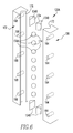
- FIG. 7 is a schematic perspective view of the alternative weighing apparatus that employs the connection apparatus of FIG. 7 ;
- FIG. 8 is a sectional view as taken along line 8 - 8 of FIG. 7 .
- FIG. 1 An improved weighing apparatus 4 in accordance with one embodiment of the disclosed and claimed concept is depicted in FIG. 1 as being a part of an improved material handling device 6 that is likewise in accordance with the disclosed and claimed concept.
- the exemplary material handling device 6 that is depicted herein is a forklift truck that further includes a truck 8 , a lift mechanism 10 , and a set of forks 12 . It is understood, however, that the weighing apparatus 4 can be implemented in any of a variety of types of material handling devices such as tipper lifts and other devices without departing from the present concept.
- the forks 12 are situated on the weighing apparatus 4 , and the weighing apparatus 4 is, in turn, mounted to the lift mechanism 10 .
- the lift mechanism 10 includes a pair of masts that are mounted to the truck 8 .
- the truck 8 includes an engine or other type of device that provides motile force to a set of wheels to enable the material handling device 6 to be driven and steered from one location to another. It is understood that the weighing apparatus 4 can be not only provided with a material handling device 6 as a part of the original equipment, but the weighing apparatus 4 can additionally be employed to retrofit an existing forklift or other such device to result in the improved material handling device 6 .
- the forks 12 form a protuberant platform that protrudes from the weighing apparatus 4 in a protrusion direction 16 which can generally be described as being generally parallel with the forward direction of motion of the exemplary material handling device 6 .
- the lift mechanism 10 is configured to move the weighing apparatus 4 and the forks that are situated thereon, plus a load 14 that is situated on the forks 12 , along a movement direction 18 that is generally orthogonal to the protrusion direction 16 and that is depicted in an exemplary fashion as being in the vertical direction from the perspective of FIG. 1 .
- the weighing apparatus 4 is configured to permit certain relative movement of some of its components along the movement direction 18 while resisting relative movement of such structures in directions other than the movement direction, which would include resisting movement in the protrusion direction 16 and in a lateral direction 20 that is mutually orthogonal to the protrusion direction 16 and the movement direction 18 .
- the improved weighing apparatus 4 avoids binding of the various structures of the weighing apparatus 4 with one another, which therefore avoids friction therebetween and permits an accurate measurement of the weight of the load 14 .
- the weighing apparatus 4 includes a front plate 22 that serves as a support, a rear plate 24 that serves as another support, a pair of connection apparatuses 26 A and 26 B, and a load cell apparatus 28 .
- the front and rear plates 22 and 24 are each plate-like structures that are of a generally planar nature and that are oriented parallel with one another and spaced apart.
- the connection apparatuses 26 A and 26 B are each interposed between the front and rear plates 22 and 24 and are spaced apart from one another along the lateral direction 20 to be situated generally at the marginal regions of the front and rear plates 22 and 24 .
- connection apparatuses 26 A and 26 B that are depicted in FIGS. 1 and 2 are mirror images of one another and each include an inboard rail 30 that serves as an inboard support, an outboard rail 32 that serves as an outboard support, and a number of engagement structures 34 that are interposed in various fashions between the inboard and outboard rails 30 and 32 .
- the expression “a number of” and variations thereof shall refer broadly to any non-zero quantity, including a quantity of one.
- the exemplary engagement structures 34 that are depicted herein include rollable structures that are at least partially rounded and that may be in the form of spheres or cylinders, by way of example, or other shapes, and further include other structures that will be set forth in greater detail below.
- the engagement structures 34 are movable with respect to at least one of the inboard rail 30 and the outboard rail 32 and thereby permit at least one of the inboard rail 30 and the outboard rail 32 to be movable with respect to the other of the inboard rail 30 and the outboard rail 32 .
- the engagement structures 34 further resist relative movement between the inboard rail 30 and the outboard rail 32 in the protrusion direction 16 and in the movement direction 18 , meaning that the engagement structures 34 resist relative movement of the inboard and outboard rails 30 and 32 with respect to one another in directions other than the movement direction 18 .
- Such resistance to movement in directions other than the movement direction 18 advantageously avoids binding of the structures of the connection apparatuses 26 A and 26 B and thus enables the load cell apparatus 28 to have applied thereto a loading that is representative in an accurate fashion of the load 14 , which enables the load cell apparatus 28 to thereby generate an output that is representative of the weight of the load 14 in an accurate and Legal for Trade fashion.
- the schematically-depicted load cell apparatus 28 includes an upper plate 36 that is affixed to a surface 37 of the front plate 22 , a lower plate 38 that is affixed to a surface 39 of the rear plate 24 , and a load cell 40 that is situated on the lower plate 38 and that is interposed between the upper and lower plates 36 and 38 .
- the load cell 40 When the load 14 is applied to the forks 12 , the weight thereof causes a slight movement of the front plate 22 in the movement direction 18 with respect to the rear plate 24 which engages the upper plate 36 with the load cell 40 and applies to the load cell 40 an accurate representation of the weight of the load 14 .
- This enables the load cell 40 to generate an output that is representative of the weight of the load 14 .
- the load cell 40 generates as an output some type of an electronic signal that is detected by a computer and that is subject to various processing on the computer that may include storage and other operations on the computer.
- the surfaces 37 and 39 are oriented generally parallel with one another and are in a face-to-face relationship, meaning that they confront one another.
- the surfaces 37 and 39 more particularly confront one another and overlap one another along the protrusion direction 16 .
- connection apparatuses 26 A and 26 B are mirror images of one another, the connection apparatuses 26 A and 26 B may be collectively and individually referred to herein with the numeral 26 .
- the exemplary inboard and outboard rails 30 and 32 are identical to one another and are merely arranged in different orientations with respect to the front and rear plates 22 and 24 .
- the connection apparatus 26 will be described herein in terms of it including the inboard rail 30 , the outboard rail 32 , and the engagement structures 34 .
- the inboard rail 30 includes an inboard shank 42 that is elongated along the movement direction 18 .
- the inboard rail 30 further includes a first inboard lug 40 having a first inboard lug face 46 and being situated at a first end of the inboard shank 42 .
- the inboard rail 30 includes a second inboard lug 48 having a second inboard lug face 50 and being situated at a second, opposite end of the inboard shank 42 .
- the first and second inboard lugs 44 and 48 are spaced apart from one another along the movement direction 18 .
- the first and second inboard lugs 44 and 48 extend from the inboard shank 42 in generally the same direction, which is in a direction generally toward the outboard rail 32 and away from the opposite connection apparatus 26 . It can also be seen that the first and second inboard lugs 44 and 48 each extend from the inboard shank 42 in a direction generally transverse to its longitudinal extent. However, the first and second inboard lug faces 46 and 50 face in generally opposite directions along the protrusion direction 16 .
- the outboard rail 32 likewise includes an elongated outboard shank 52 , a first outboard lug 54 having a first outboard lug face 56 and being situated at a first end of the outboard shank 52 , and a second outboard lug 60 having a second outboard lug face 62 and being situated at a second, opposite end of the outboard shank 52 .
- the first and second inboard lug faces 46 and 50 and the first and second outboard lug faces 56 and 62 are each of a generally planar configuration for reasons that will be set forth in greater detail below.
- the first and second inboard and outboard lugs 44 , 48 , 54 , and 60 each serve as retention structures that resist movement of the front plate 22 in a direction along the protrusion direction 16 with respect to the rear plate 24 .
- the first and second inboard lugs 44 and 48 overlap and confront one another along the protrusion direction 16
- the first and second outboard lugs 54 and 60 likewise overlap and confront one another along the protrusion direction 16 .
- the inboard rail 30 has a plurality of inboard fastening holes 64 formed therein that are threaded and that are cooperable with a set of inboard bolts 66 to affix the inboard rail 30 to the rear plate 24 .
- the outboard rail 32 has a plurality of outboard fastener holes 68 that are threaded and that are cooperable with a set of outboard bolts 70 to mount the outboard rail 32 to the front plate 22 . That is, the inboard rails 30 of the connection apparatuses 26 A and 26 B are together mounted to the rear plate 24 , and the outboard rails 32 of the connection apparatuses 26 A and 26 B are together mounted to the front plate 22 . It is understood, however, that different methodologies can be employed to attach the inboard rails 30 and the outboard rails 32 to the rear and front plate 24 and 22 , respectively.
- the inboard rail 30 is depicted in FIGS. 2 and 3 as including a first inboard receptacle 72 and a second inboard receptacle 74 that are formed in the inboard shank 42 and that are spaced apart from one another along the movement direction 18 .
- the first and second inboard receptacles 72 and 74 are each elongated, at least slightly, along the movement direction 18 .
- the outboard rail 32 likewise has a first outboard receptacle 76 and a second outboard receptacle 78 that are formed in the outboard shank 52 , that are similarly spaced apart, and that are each elongated, at least slightly, along the movement direction 18 .
- the first inboard and outboard receptacles 72 and 76 confront one another along the lateral direction 20
- the second inboard and outboard receptacles 74 and 78 likewise confront one another along the lateral direction 20 .
- a spherical engagement structure 34 A of the number of engagement structures 34 is received in the confronting first inboard and outboard receptacles 72 and 76 , and a polymeric engagement structure 34 B of the number of engagement structures 34 is disposed vertically below the spherical engagement structure 34 A within the first inboard and outboard receptacles 72 and 76 .
- the polymeric engagement structure 34 B is, in the example depicted herein, formed of Delrin, although other appropriate materials may be employed without departing from the present concept.
- Another spherical engagement structure 34 A and another polymeric engagement structure 34 B that is situated vertically therebelow are likewise received in the second inboard and outboard receptacles 74 and 78 .
- the spherical engagement structures 34 A are each engageable with the corresponding polymeric engagement structure 34 B, and the polymeric engagement structures 34 B provide a low friction interface to avoid the spherical engagement structures 34 A from binding with other structures of the connection apparatuses 26 .
- the spherical engagement structures 34 A and/or the first and second inboard and outboard receptacles 72 , 74 , 76 , and 78 are shaped and sized such that the inboard and outboard shanks 42 and 52 remain at least slightly spaced apart when the connection apparatus is assembled, as is depicted generally in FIGS. 4 and 4A , which advantageously further resists the inboard and outboard shanks 42 and 52 from binding against one another.
- first and second inboard and outboard receptacles 72 , 74 , 76 , and 78 are each of an approximately trapezoidal cross-section whereby the spherical engagement structures 34 A engage the non-parallel surfaces of the opposed first and second inboard and outboard receptacles 72 , 74 , 76 , and 78 .
- the spherical engagement structures 34 A area each rollably movable with respect to at least one of the inboard and outboard shanks 42 and 52 to permit relative movement of the inboard and outboard shanks 42 and 52 along the movement direction 18 .
- Such reception of the spherical engagement structures 34 in the first and second inboard and outboard receptacles 72 , 74 , 76 , and 78 furthermore resists movement of the front plate 22 with respect to the rear plate 24 along the lateral direction 20 . More particularly, as a result of the spherical engagement structures 34 being received in the first and second inboard and outboard receptacles 72 , 74 , 76 , and 78 , the inboard and outboard shanks 42 and 52 of each connection apparatus 26 can be situated no closer to one another than is depicted generally in FIGS. 4 and 4A . Since, as can be seen in FIG.
- the inboard rails 30 are situated adjacent one another (albeit spaced apart), and the two inboard rails 30 are furthermore situated between the two outboard rails 32 , the reception of the spherical engagement structures 34 A between each inboard rail 30 and its corresponding outboard rail 32 resists any movement of either of the inboard and outboard rails 30 and 32 with respect to one another in the lateral direction 20 .
- both of the inboard rails 30 are affixed to the rear plate 24
- both outboard rails 32 are affixed to the front plate 22 .
- the spherical engagement structures 34 A resist relative movement of the front and rear plates 22 and 24 along the lateral direction 20 while permitting movement of the outboard rails 32 with respect to the inboard rails 30 along the movement direction 18 .
- the spherical engagement structures 34 A can additionally be said to resist relative movement of the front and rear plates 22 and 24 along the protrusion direction 16 while permitting relative movement of the inboard and outboard rails 30 and 32 along the movement direction 16 .
- the inboard rails 30 may be engaged with the spherical engagement structures 34 A and the corresponding outboard rails 32 with a predetermined compressive preload in order to retain the connection apparatuses 26 in the assembled condition that is depicted generally in FIG. 4 .
- certain of the inboard and/or outboard fastener holes 64 and 68 may be elongated along the lateral direction 20 to permit such lateral preloading of the connection apparatuses 26 prior to tightening of the inboard and/or outboard bolts 66 and 70 .
- a set of cylindrical engagement structures 34 C of the number of engagement structures 34 are interposed between the first inboard and outboard lugs 44 and 54 and, more particularly, are engaged between the first inboard and outboard lug faces 46 and 56 .
- the first inboard and outboard lug faces 46 and 56 can be understood to be confronting one another along the protrusion direction 16 , with the number of cylindrical engagement structures 34 C being interposed therebetween when the connection apparatus 26 is in the assembled condition that is depicted generally in FIG. 4 .
- first inboard and outboard lugs 44 and 54 can be seen to overlap one another along the protrusion direction 16 when the connection apparatus 26 is in the assembled configuration of FIG. 4
- the second inboard and outboard lugs 48 and 60 likewise overlap one another along the protrusion direction 16 when the connection apparatus 26 is in its assembled condition.
- first outboard lug 54 and the corresponding cylindrical engagement structures 34 C are disposed between the first inboard lug 44 and the rear plate 24 whereas the second outboard lug 60 and the corresponding cylindrical engagement structures 34 C are disposed between the second inboard lug 48 and the front plate 22 .
- Such an arrangement advantageously resists the moment loads that are applied by the forks 12 to the front plate 22 from causing binding between the inboard and outboard rails 30 and 32 . More particularly, when the load 14 is applied to the forks 12 in the fashion depicted generally in FIG.
- the moment forces applied by the forks 12 to the front plate 22 tend to pull the upper portion of the front plate 22 (from the perspective of FIG. 1 ) in a direction generally away from the rear plate 24 whereas the same moment forces cause the lower portion of the front plate 22 (from the perspective of FIG. 1 ) to be compressively engaged toward the rear plate 24 .
- the first and second inboard and outboard lugs 44 , 48 , 54 , and 60 in the fashion depicted in FIG.
- the surface 39 of the rear plate 24 has a pair of inboard indentations 86 formed therein that are configured to receive the inboard shank 42 and the second inboard lug 40 .
- the surface 37 has a pair of outboard indentations 82 formed therein that are configured to receive the outboard shank 52 and the second outboard lug 60 .
- the bottom-most edge (from the perspective of FIG.
- each of the outboard indentations 82 provide an outboard ledge 88 that is engaged with the outboard shank 52 and the second outboard lug 60 and which thereby provides vertical support, i.e., support along the movement direction 18 , to the entire outboard rail 32 .
- the bottom-most edge (from the perspective of FIGS. 2 and 5B ) of each inboard indentation 86 provides an inboard ledge 90 that is engageable with the inboard shank 42 and the second inboard lug 48 and provides vertical support along the movement direction 18 to the entire inboard rail 30 .
- Such outboard and inboard ledges 88 and 90 facilitate retention of the outboard and inboard rails 32 and 30 respectively, with respect to the front and rear plates 22 and 24 and with respect to one another, without the need to rely solely upon the shear strength and the torque-based tensile loading of the inboard and outboard bolts 66 and 70 to provide such retention.
- This advantageously avoids deformation of the inboard and outboard rails 30 and 32 , which correspondingly avoids binding of any of the structures of the weighing apparatus 4 with one another.
- This promotes movement of the front plate 22 with respect to the rear plate 24 along the movement direction 18 while resisting relative movement therebetween along the protrusion direction 16 and the lateral direction 20 .
- the configuration of the weighing apparatus 4 thus advantageously enables the weight of the load 14 to be accurately applied to the load cell 40 to enable the load cell 40 to output a signal that is representative of the weight of the load 14 with a Legal for Trade accuracy.
- connection apparatus 126 A in accordance with an alternative embodiment of the disclosed and claimed concept is depicted generally in FIG. 6 in an exploded condition.
- the connection apparatus 126 A is one of a pair of connection apparatuses 126 A and 126 B that are mirror images of one another and that are usable in an improved weighing apparatus 104 in accordance with an alternative embodiment of the disclosed and claimed concept.
- the weighing apparatus 104 can be employed in place of the weighing apparatus 4 to form another embodiment of the material handling device 6 .
- the improved weighing apparatus 104 includes a front plate 122 and a rear plate 124 , and disposed therebetween are the pair of connection apparatuses 126 A and 126 B (which may be referred to herein collectively or individually with the numeral 126 ).
- the connection apparatuses 126 permit movement of the front plate 122 with respect to the rear plate 124 along the movement direction 18 while resisting relative movement therebetween along the protrusion direction 16 and along the lateral direction 20 .
- the connection apparatus 126 includes an inboard rail 130 and an outboard rail 132 along with a number of engagement structures 134 .
- the inboard rail 130 has an inboard receptacle 172 formed therein that is elongated and that extends along the longitudinal extent of the inboard rail 130 .
- the outboard rail 132 likewise has an outboard receptacle 176 formed therein that is elongated and that extends along the longitudinal extent of the outboard rail 132 .
- the engagement structures 134 include a plurality of spherical engagement structures 134 A that are received in the inboard and outboard receptacles 172 and 176 when the connection apparatus 126 is in the assembled condition depicted generally in FIGS. 7 and 8 .
- the engagement structures further include a number of polymeric engagement structures 134 B that are generally wedge-shaped and that are received in the inboard and outboard receptacles 172 and 176 at the marginal regions thereof.
- the polymeric engagement structures 134 B are, in the depicted exemplary embodiment, formed of Delrin and retain the spherical engagement structures 134 A between the inboard and outboard receptacles 172 and 176 while resisting binding of any of the structures of the connection apparatus 126 with one another.
- the polymeric engagement structures 134 B can be affixed to the inboard receptacle 172 and the outboard receptacle 176 in any of a variety of fashions, such as with the use of threaded fasteners, retention structures, and the like without limitation.
- the inboard rail 130 has a set of inboard fastener holes 164 formed therein that are threaded and that are cooperable with a set of inboard bolts 166 to mount the inboard rail to the rear plate 124 .
- the outboard rail 132 has a set of outboard fastener holes 168 formed therein that are threaded and that are cooperable with a set of outboard bolts 170 to attach the outboard rail 132 to the front plate 122 .
- the front and rear plates 122 and 124 each have a pair of outboard and inboard indentations 182 and 186 formed therein, respectively, that receive therein the outboard and inboard rails 132 and 130 , respectively.
- the outboard and inboard indentations 182 and 186 each terminate at their lower ends (from the perspective of FIG. 7 ) at a ledge that is engageable with the bottom edge of the outboard and inboard rails 132 and 130 , respectively.
- These ledges which are similar to the inboard and outboard ledges 90 and 88 , provide support to the outboard and inboard rails 132 and 130 , and to help retain the outboard and inboard rails 132 and 130 in position with respect to one another and with respect to the front and rear plates 122 and 124 .
- the reception of the spherical engagement structures 134 in the inboard and outboard receptacles 172 and 176 resists relative motion between the inboard and outboard rails 130 and 132 in the protrusion and lateral directions 16 and 20 while permitting relative movement therebetween along the movement direction 18 .
- the resisting of relative movement along the protrusion and lateral directions 16 and 20 resists binding of the structures of the weighing apparatus 104 with one another, which advantageously permits the weight of the load 14 to be accurately applied to a load cell apparatus of the weighing apparatus 104 , the thereby permit the load cell apparatus of the weighing apparatus 104 to output a signal that is representative of the weight of the load 14 with a Legal for Trade accuracy.
Abstract
Description
Claims (22)
Priority Applications (1)
| Application Number | Priority Date | Filing Date | Title |
|---|---|---|---|
| US14/503,862 US9187303B2 (en) | 2013-10-02 | 2014-10-01 | Material handling device and weighing apparatus usable therewith |
Applications Claiming Priority (2)
| Application Number | Priority Date | Filing Date | Title |
|---|---|---|---|
| US201361885555P | 2013-10-02 | 2013-10-02 | |
| US14/503,862 US9187303B2 (en) | 2013-10-02 | 2014-10-01 | Material handling device and weighing apparatus usable therewith |
Publications (2)
| Publication Number | Publication Date |
|---|---|
| US20150093216A1 US20150093216A1 (en) | 2015-04-02 |
| US9187303B2 true US9187303B2 (en) | 2015-11-17 |
Family
ID=52740347
Family Applications (1)
| Application Number | Title | Priority Date | Filing Date |
|---|---|---|---|
| US14/503,862 Expired - Fee Related US9187303B2 (en) | 2013-10-02 | 2014-10-01 | Material handling device and weighing apparatus usable therewith |
Country Status (2)
| Country | Link |
|---|---|
| US (1) | US9187303B2 (en) |
| WO (1) | WO2015050962A1 (en) |
Cited By (2)
| Publication number | Priority date | Publication date | Assignee | Title |
|---|---|---|---|---|
| US11130660B2 (en) | 2020-01-08 | 2021-09-28 | Cascade Corporation | Lift truck attachments |
| US11365104B2 (en) | 2020-01-08 | 2022-06-21 | Cascade Corporation | Attachments for industrial material handling equipment |
Families Citing this family (4)
| Publication number | Priority date | Publication date | Assignee | Title |
|---|---|---|---|---|
| US9562804B2 (en) * | 2013-03-14 | 2017-02-07 | Larry D. Santi | Forklift scale, load cell thereof and method of measuring a forklift load |
| WO2014144560A1 (en) * | 2013-03-15 | 2014-09-18 | Santi Larry D | Waste bin scale, load cell and method of measuring a waste bin load |
| US11536603B2 (en) * | 2019-03-25 | 2022-12-27 | Illinois Tool Works Inc. | Forklift scale attachment |
| WO2023147214A1 (en) * | 2022-01-27 | 2023-08-03 | Illinois Tool Works Inc. | A modular carriage width adjustment system |
Citations (15)
| Publication number | Priority date | Publication date | Assignee | Title |
|---|---|---|---|---|
| US1887169A (en) | 1931-02-19 | 1932-11-08 | Clifford O Ross | Weighing scale |
| US2850181A (en) | 1953-11-27 | 1958-09-02 | Union Metal Mfg Co | Scale for lift truck or the like |
| US3231035A (en) * | 1963-10-28 | 1966-01-25 | Hydroway Scales Inc | Load weighing system |
| US3910363A (en) * | 1974-12-27 | 1975-10-07 | Allegany Technology Inc | Weighing device for fork lift truck |
| US4323132A (en) * | 1980-08-25 | 1982-04-06 | Weigh-Tronix, Inc. | Mounting adapter for a fork lift truck |
| US4421186A (en) * | 1980-08-25 | 1983-12-20 | Weigh-Tronix, Inc. | Fork lift scale |
| US4491190A (en) * | 1983-01-31 | 1985-01-01 | Mayfield Harvey G | Weight measurement apparatus |
| DE3744194A1 (en) | 1987-12-24 | 1989-07-06 | Pfreundt Gmbh Waege Und Foerde | Fork-lift truck with weighing device |
| US5336854A (en) * | 1992-04-03 | 1994-08-09 | Weigh-Tronix, Inc. | Electronic force sensing load cell |
| US5837946A (en) * | 1995-06-16 | 1998-11-17 | Weigh-Tronix, Inc. | Force sensitive scale and dual load sensor cell for use therewith |
| US7026557B2 (en) * | 2003-10-30 | 2006-04-11 | Mettler-Toledo | Apparatus and method for weighting objects on a fork lift truck |
| US20090260924A1 (en) * | 2008-04-18 | 2009-10-22 | Mettler-Toledo, Inc. | Forklift scale |
| US20140133944A1 (en) * | 2012-11-12 | 2014-05-15 | Lts Scale Company, Llc | Detection System Usable In Forklift Apparatus |
| US20140262552A1 (en) * | 2013-03-15 | 2014-09-18 | Larry D. Santi | Waste bin scale, load cell and method of measuring a waste bin load |
| US9046409B2 (en) * | 2009-08-13 | 2015-06-02 | Seng Siong Siaw | Weighing scale for forklift for measuring weight of loads as they are lifted |
-
2014
- 2014-10-01 US US14/503,862 patent/US9187303B2/en not_active Expired - Fee Related
- 2014-10-01 WO PCT/US2014/058581 patent/WO2015050962A1/en active Application Filing
Patent Citations (16)
| Publication number | Priority date | Publication date | Assignee | Title |
|---|---|---|---|---|
| US1887169A (en) | 1931-02-19 | 1932-11-08 | Clifford O Ross | Weighing scale |
| US2850181A (en) | 1953-11-27 | 1958-09-02 | Union Metal Mfg Co | Scale for lift truck or the like |
| US3231035A (en) * | 1963-10-28 | 1966-01-25 | Hydroway Scales Inc | Load weighing system |
| US3910363A (en) * | 1974-12-27 | 1975-10-07 | Allegany Technology Inc | Weighing device for fork lift truck |
| US4323132A (en) * | 1980-08-25 | 1982-04-06 | Weigh-Tronix, Inc. | Mounting adapter for a fork lift truck |
| US4421186A (en) * | 1980-08-25 | 1983-12-20 | Weigh-Tronix, Inc. | Fork lift scale |
| US4491190A (en) * | 1983-01-31 | 1985-01-01 | Mayfield Harvey G | Weight measurement apparatus |
| DE3744194A1 (en) | 1987-12-24 | 1989-07-06 | Pfreundt Gmbh Waege Und Foerde | Fork-lift truck with weighing device |
| US5336854A (en) * | 1992-04-03 | 1994-08-09 | Weigh-Tronix, Inc. | Electronic force sensing load cell |
| US5837946A (en) * | 1995-06-16 | 1998-11-17 | Weigh-Tronix, Inc. | Force sensitive scale and dual load sensor cell for use therewith |
| US7026557B2 (en) * | 2003-10-30 | 2006-04-11 | Mettler-Toledo | Apparatus and method for weighting objects on a fork lift truck |
| US20090260924A1 (en) * | 2008-04-18 | 2009-10-22 | Mettler-Toledo, Inc. | Forklift scale |
| US8353388B2 (en) * | 2008-04-18 | 2013-01-15 | Mettler-Toledo, LLC | Forklift scale |
| US9046409B2 (en) * | 2009-08-13 | 2015-06-02 | Seng Siong Siaw | Weighing scale for forklift for measuring weight of loads as they are lifted |
| US20140133944A1 (en) * | 2012-11-12 | 2014-05-15 | Lts Scale Company, Llc | Detection System Usable In Forklift Apparatus |
| US20140262552A1 (en) * | 2013-03-15 | 2014-09-18 | Larry D. Santi | Waste bin scale, load cell and method of measuring a waste bin load |
Cited By (2)
| Publication number | Priority date | Publication date | Assignee | Title |
|---|---|---|---|---|
| US11130660B2 (en) | 2020-01-08 | 2021-09-28 | Cascade Corporation | Lift truck attachments |
| US11365104B2 (en) | 2020-01-08 | 2022-06-21 | Cascade Corporation | Attachments for industrial material handling equipment |
Also Published As
| Publication number | Publication date |
|---|---|
| WO2015050962A1 (en) | 2015-04-09 |
| US20150093216A1 (en) | 2015-04-02 |
Similar Documents
| Publication | Publication Date | Title |
|---|---|---|
| US9187303B2 (en) | Material handling device and weighing apparatus usable therewith | |
| US8353388B2 (en) | Forklift scale | |
| US5600104A (en) | Load cell having reduced sensitivity to non-symmetrical beam loading | |
| EP3818345A1 (en) | Weighing load cells and arrangements employing them in shelves | |
| US20080006450A1 (en) | Load Cell Having A Base With A Curved Surface | |
| US11092477B2 (en) | Planar load cell assembly | |
| CA2850149C (en) | Load sensing system with flexure plate | |
| CN104229679B (en) | Forklift scale weighing module and forklift with same | |
| CA1144194A (en) | Load cell overload protection device | |
| GB2491848A (en) | Floor assembly with load sensor sandwiched between relatively moveable surfaces | |
| CN113905973A (en) | Forklift scale attachment | |
| US11828645B2 (en) | Weigh scale technology | |
| JP2008174379A (en) | Load detecting device for elevator | |
| CN204079387U (en) | A kind of Balancer for fork trucks Weighing module and there is its fork truck | |
| US20110061946A1 (en) | Platform scale using slot block load cells | |
| JPH07260554A (en) | Weight detecting device for forklift | |
| US20170219417A1 (en) | Weight measurement system | |
| JP3165950U (en) | Scale built-in fork | |
| CN216012434U (en) | Prevent changeing prevent dynamometry weighing module that topples | |
| SU1035428A1 (en) | Balance | |
| KR100481378B1 (en) | Load cell for a vehicle scale | |
| CN102506972A (en) | Automobile lifting weighting mechanism | |
| CN207581091U (en) | A kind of no-load measuring system of balance coefficient of elevator | |
| AU2015258316A1 (en) | Load Measuring Device | |
| JP2004069323A5 (en) |
Legal Events
| Date | Code | Title | Description |
|---|---|---|---|
| AS | Assignment |
Owner name: LTS SCALE COMPANY, LLC, OHIO Free format text: ASSIGNMENT OF ASSIGNORS INTEREST;ASSIGNORS:PANGRAZIO, JOHN A.;PANGRAZIO, ROBERT T.;MARIEA, STEVE;REEL/FRAME:034382/0691 Effective date: 20141010 |
|
| AS | Assignment |
Owner name: LTS METROLOGY, LLC, OHIO Free format text: ASSIGNMENT OF ASSIGNORS INTEREST;ASSIGNOR:LTS SCALE COMPANY, LLC;REEL/FRAME:035672/0784 Effective date: 20150504 |
|
| AS | Assignment |
Owner name: ENTERPRISE BANK & TRUST, KANSAS Free format text: SECURITY INTEREST;ASSIGNOR:LTS METROLOGY, LLC;REEL/FRAME:036143/0440 Effective date: 20150504 |
|
| STCF | Information on status: patent grant |
Free format text: PATENTED CASE |
|
| FEPP | Fee payment procedure |
Free format text: MAINTENANCE FEE REMINDER MAILED (ORIGINAL EVENT CODE: REM.); ENTITY STATUS OF PATENT OWNER: SMALL ENTITY |
|
| AS | Assignment |
Owner name: NIELCO., INC. D.B.A. LTS SCALE, OHIO Free format text: ASSIGNMENT OF ASSIGNORS INTEREST;ASSIGNOR:LTS METROLOGY, LLC;REEL/FRAME:051066/0596 Effective date: 20191107 |
|
| LAPS | Lapse for failure to pay maintenance fees |
Free format text: PATENT EXPIRED FOR FAILURE TO PAY MAINTENANCE FEES (ORIGINAL EVENT CODE: EXP.); ENTITY STATUS OF PATENT OWNER: SMALL ENTITY |
|
| STCH | Information on status: patent discontinuation |
Free format text: PATENT EXPIRED DUE TO NONPAYMENT OF MAINTENANCE FEES UNDER 37 CFR 1.362 |
|
| FP | Expired due to failure to pay maintenance fee |
Effective date: 20191117 |