US9175826B2 - Illuminating unit and display - Google Patents
Illuminating unit and display Download PDFInfo
- Publication number
- US9175826B2 US9175826B2 US13/787,286 US201313787286A US9175826B2 US 9175826 B2 US9175826 B2 US 9175826B2 US 201313787286 A US201313787286 A US 201313787286A US 9175826 B2 US9175826 B2 US 9175826B2
- Authority
- US
- United States
- Prior art keywords
- light
- unit cells
- optical member
- axis direction
- uniformizing optical
- Prior art date
- Legal status (The legal status is an assumption and is not a legal conclusion. Google has not performed a legal analysis and makes no representation as to the accuracy of the status listed.)
- Expired - Fee Related, expires
Links
- 230000003287 optical effect Effects 0.000 claims abstract description 113
- 239000004973 liquid crystal related substance Substances 0.000 claims description 31
- 238000005286 illumination Methods 0.000 claims description 30
- 239000011295 pitch Substances 0.000 claims description 19
- 238000006073 displacement reaction Methods 0.000 claims description 11
- 238000003491 array Methods 0.000 claims description 10
- 239000004065 semiconductor Substances 0.000 claims description 7
- QNRATNLHPGXHMA-XZHTYLCXSA-N (r)-(6-ethoxyquinolin-4-yl)-[(2s,4s,5r)-5-ethyl-1-azabicyclo[2.2.2]octan-2-yl]methanol;hydrochloride Chemical compound Cl.C([C@H]([C@H](C1)CC)C2)CN1[C@@H]2[C@H](O)C1=CC=NC2=CC=C(OCC)C=C21 QNRATNLHPGXHMA-XZHTYLCXSA-N 0.000 claims description 6
- 230000004048 modification Effects 0.000 description 38
- 238000012986 modification Methods 0.000 description 38
- 230000010287 polarization Effects 0.000 description 18
- 230000000052 comparative effect Effects 0.000 description 15
- 230000008878 coupling Effects 0.000 description 13
- 238000010168 coupling process Methods 0.000 description 13
- 238000005859 coupling reaction Methods 0.000 description 13
- 238000010586 diagram Methods 0.000 description 11
- 230000007480 spreading Effects 0.000 description 8
- 238000005516 engineering process Methods 0.000 description 6
- 239000000203 mixture Substances 0.000 description 5
- 230000009467 reduction Effects 0.000 description 5
- 239000011159 matrix material Substances 0.000 description 4
- 230000008901 benefit Effects 0.000 description 3
- 239000013078 crystal Substances 0.000 description 3
- 230000000694 effects Effects 0.000 description 3
- XUIMIQQOPSSXEZ-UHFFFAOYSA-N Silicon Chemical compound [Si] XUIMIQQOPSSXEZ-UHFFFAOYSA-N 0.000 description 1
- 230000004075 alteration Effects 0.000 description 1
- 239000003086 colorant Substances 0.000 description 1
- 230000003467 diminishing effect Effects 0.000 description 1
- 230000005284 excitation Effects 0.000 description 1
- 230000001747 exhibiting effect Effects 0.000 description 1
- 230000006872 improvement Effects 0.000 description 1
- 238000000034 method Methods 0.000 description 1
- 230000002265 prevention Effects 0.000 description 1
- 230000004044 response Effects 0.000 description 1
- 229910052710 silicon Inorganic materials 0.000 description 1
- 239000010703 silicon Substances 0.000 description 1
- 239000000758 substrate Substances 0.000 description 1
- 230000001629 suppression Effects 0.000 description 1
Images


Classifications
-
- F—MECHANICAL ENGINEERING; LIGHTING; HEATING; WEAPONS; BLASTING
- F21—LIGHTING
- F21V—FUNCTIONAL FEATURES OR DETAILS OF LIGHTING DEVICES OR SYSTEMS THEREOF; STRUCTURAL COMBINATIONS OF LIGHTING DEVICES WITH OTHER ARTICLES, NOT OTHERWISE PROVIDED FOR
- F21V5/00—Refractors for light sources
- F21V5/04—Refractors for light sources of lens shape
-
- G—PHYSICS
- G02—OPTICS
- G02B—OPTICAL ELEMENTS, SYSTEMS OR APPARATUS
- G02B27/00—Optical systems or apparatus not provided for by any of the groups G02B1/00 - G02B26/00, G02B30/00
- G02B27/09—Beam shaping, e.g. changing the cross-sectional area, not otherwise provided for
-
- G—PHYSICS
- G02—OPTICS
- G02B—OPTICAL ELEMENTS, SYSTEMS OR APPARATUS
- G02B27/00—Optical systems or apparatus not provided for by any of the groups G02B1/00 - G02B26/00, G02B30/00
- G02B27/09—Beam shaping, e.g. changing the cross-sectional area, not otherwise provided for
- G02B27/0905—Dividing and/or superposing multiple light beams
-
- G—PHYSICS
- G02—OPTICS
- G02B—OPTICAL ELEMENTS, SYSTEMS OR APPARATUS
- G02B27/00—Optical systems or apparatus not provided for by any of the groups G02B1/00 - G02B26/00, G02B30/00
- G02B27/09—Beam shaping, e.g. changing the cross-sectional area, not otherwise provided for
- G02B27/0938—Using specific optical elements
- G02B27/095—Refractive optical elements
- G02B27/0955—Lenses
- G02B27/0961—Lens arrays
-
- G—PHYSICS
- G02—OPTICS
- G02B—OPTICAL ELEMENTS, SYSTEMS OR APPARATUS
- G02B27/00—Optical systems or apparatus not provided for by any of the groups G02B1/00 - G02B26/00, G02B30/00
- G02B27/10—Beam splitting or combining systems
- G02B27/12—Beam splitting or combining systems operating by refraction only
- G02B27/123—The splitting element being a lens or a system of lenses, including arrays and surfaces with refractive power
-
- G—PHYSICS
- G02—OPTICS
- G02B—OPTICAL ELEMENTS, SYSTEMS OR APPARATUS
- G02B27/00—Optical systems or apparatus not provided for by any of the groups G02B1/00 - G02B26/00, G02B30/00
- G02B27/48—Laser speckle optics
-
- G—PHYSICS
- G03—PHOTOGRAPHY; CINEMATOGRAPHY; ANALOGOUS TECHNIQUES USING WAVES OTHER THAN OPTICAL WAVES; ELECTROGRAPHY; HOLOGRAPHY
- G03B—APPARATUS OR ARRANGEMENTS FOR TAKING PHOTOGRAPHS OR FOR PROJECTING OR VIEWING THEM; APPARATUS OR ARRANGEMENTS EMPLOYING ANALOGOUS TECHNIQUES USING WAVES OTHER THAN OPTICAL WAVES; ACCESSORIES THEREFOR
- G03B21/00—Projectors or projection-type viewers; Accessories therefor
- G03B21/14—Details
- G03B21/20—Lamp housings
- G03B21/208—Homogenising, shaping of the illumination light
-
- H—ELECTRICITY
- H04—ELECTRIC COMMUNICATION TECHNIQUE
- H04N—PICTORIAL COMMUNICATION, e.g. TELEVISION
- H04N9/00—Details of colour television systems
- H04N9/12—Picture reproducers
- H04N9/31—Projection devices for colour picture display, e.g. using electronic spatial light modulators [ESLM]
- H04N9/3102—Projection devices for colour picture display, e.g. using electronic spatial light modulators [ESLM] using two-dimensional electronic spatial light modulators
- H04N9/3111—Projection devices for colour picture display, e.g. using electronic spatial light modulators [ESLM] using two-dimensional electronic spatial light modulators for displaying the colours sequentially, e.g. by using sequentially activated light sources
-
- H—ELECTRICITY
- H04—ELECTRIC COMMUNICATION TECHNIQUE
- H04N—PICTORIAL COMMUNICATION, e.g. TELEVISION
- H04N9/00—Details of colour television systems
- H04N9/12—Picture reproducers
- H04N9/31—Projection devices for colour picture display, e.g. using electronic spatial light modulators [ESLM]
- H04N9/3141—Constructional details thereof
- H04N9/315—Modulator illumination systems
- H04N9/3152—Modulator illumination systems for shaping the light beam
-
- H—ELECTRICITY
- H04—ELECTRIC COMMUNICATION TECHNIQUE
- H04N—PICTORIAL COMMUNICATION, e.g. TELEVISION
- H04N9/00—Details of colour television systems
- H04N9/12—Picture reproducers
- H04N9/31—Projection devices for colour picture display, e.g. using electronic spatial light modulators [ESLM]
- H04N9/3141—Constructional details thereof
- H04N9/315—Modulator illumination systems
- H04N9/3161—Modulator illumination systems using laser light sources
Definitions
- the present disclosure relates to an illuminating unit applying light including laser light, and a display performing image display using such an illuminating unit.
- An optical module as one of major component parts of a projector is generally configured of an illumination optical system (illuminating unit) including a light source, and a projection optical system including a light modulation device.
- illumination optical system illumination unit
- projection optical system including a light modulation device.
- a small (palm-sized) and lightweight, portable projector called microprojector is beginning to be widespread.
- microprojector a light emitting diode (LED) has been mainly used as the light source for the illuminating unit.
- laser is now the subject of interest as a new light source for the illuminating unit.
- a green semiconductor laser is being developed following the commercialization of high-output blue and red semiconductor lasers, and is reaching a practical application level. Due to such a background, there has been proposed a projector including monochrome lasers (semiconductor lasers) of three primary colors of red (R), green (G), and blue (B) as light sources for the illuminating unit.
- monochrome lasers semiconductor lasers
- R red
- G green
- B blue
- a projector having a wide color reproduction range and exhibiting small power consumption is achieved through use of the monochrome lasers as the light sources.
- such a projector generally has a predetermined uniformizing optical system (uniformizing optical member) in an illuminating unit to uniformize the light quantity distribution (intensity distribution) of illumination light emitted from the illuminating unit.
- a predetermined uniformizing optical system uniformizing optical member
- an illuminating unit to uniformize the light quantity distribution (intensity distribution) of illumination light emitted from the illuminating unit.
- Japanese Unexamined Patent Application Publication Nos. 2002-311382 and 2012-8549 each disclose two (a pair of) fly-eye lenses as the uniformizing optical member.
- An illuminating unit includes: a light source section including a laser light source; a first uniformizing optical member on which light from the light source section is incident; and a second uniformizing optical member including a plurality of first unit cells and a plurality of second unit cells and on which light from the first uniformizing optical member is incident.
- the first unit cells are arranged on a light incidence surface of the second uniformizing optical member and each have an anisotropic shape with a major-axis direction as a first direction and a minor-axis direction as a second direction.
- the second unit cells are arranged on a light emission surface of the second uniformizing optical member and each have a shape protruding along both the first direction and the second direction.
- a display includes: an illuminating unit emitting illumination light; and a light modulation device modulating the illumination light based on an image signal.
- the illuminating unit includes: a light source section including a laser light source; a first uniformizing optical member on which light from the light source section is incident; and a second uniformizing optical member including a plurality of first unit cells and a plurality of second unit cells and on which light from the first uniformizing optical member is incident.
- the first unit cells are arranged on a light incidence surface of the second uniformizing optical member and each have an anisotropic shape with a major-axis direction as a first direction and a minor-axis direction as a second direction.
- the second unit cells are arranged on a light emission surface of the second uniformizing optical member and each have a shape protruding along both the first direction and the second direction.
- the light from the light source passes through the first uniformizing optical member and the second uniformizing optical member in this order so that quantity of the light is uniformized, and the uniformized light is emitted in a form of illumination light.
- each of the first unit cells that are arranged on the light incidence surface thereof has the anisotropic shape with the major-axis direction as the first direction and the minor-axis direction as the second direction, and each of the second unit cells arranged on the light emission surface thereof has the shape protruding along both the first and second directions.
- each of the first unit cells arranged on the light incidence surface thereof has the anisotropic shape with the major-axis direction as the first direction and the minor-axis direction as the second direction
- each of the second unit cells arranged on the light emission surface thereof has the shape protruding along both the first and second directions.
- FIG. 1 is a diagram illustrating an overall configuration of a display according to an embodiment of the disclosure.
- FIGS. 2A and 2B are diagrams illustrating exemplary distribution of the quantity of laser light.
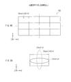
- FIGS. 3A and 3B are schematic diagrams illustrating an exemplary configuration of two fly-eye lenses illustrated in FIG. 1 .
- FIG. 4 is a schematic diagram for describing exemplary distribution of the quantity of incident light on each of the two fly-eye lenses illustrated in FIG. 1 .
- FIG. 5 is a schematic diagram for describing an allowable angle for an incident angle of incident light on a latter-stage fly-eye lens illustrated in FIG. 1 .
- FIGS. 6A and 6B are schematic diagrams illustrating an exemplary configuration and functions of a latter-stage fly-eye lens according to a comparative example 1.
- FIGS. 7A and 7B are schematic diagrams illustrating an exemplary configuration and functions of a latter-stage fly-eye lens according to a comparative example 2.
- FIG. 8 is a schematic diagram illustrating functions of the latter-stage fly-eye lens illustrated in FIG. 1 .
- FIGS. 9A and 9B are schematic diagrams illustrating an exemplary configuration and functions of a latter-stage fly-eye lens according to Modification 1.
- FIGS. 10A and 10B are schematic diagrams illustrating exemplary configurations of latter-stage fly-eye lenses according to Modifications 2 and 3, respectively.
- FIGS. 11A and 11B are schematic diagrams illustrating functions of the latter-stage fly-eye lenses according to the Modifications 2 and 3, respectively.
- Embodiment (example where a second unit cell on a light incidence surface of a second uniformizing optical member has a rhombic shape).
- each second unit cell has a cross or hexagonal shape).
- FIG. 1 illustrates an overall configuration of a display (display 3 ) according to an embodiment of the disclosure.
- the display 3 is a projection display that projects an image (image light) onto a screen 30 (a plane of projection), and includes an illuminating unit 1 , and an optical system (a display optical system) for image display using illumination light from the illuminating unit 1 .
- the illuminating unit 1 includes: a red laser 11 R; a green laser 11 G; a blue laser 11 B; coupling lenses 12 R, 12 G, and 12 B; dichroic prisms 131 and 132 ; an optical device 14 ; a drive section 140 ; fly-eye lenses 151 and 152 , sub-condenser lenses 161 and 162 ; and a condenser lens 17 .
- Z 0 represents a light axis in FIG. 1 .
- the red laser 11 R, the green laser 11 G, and the blue laser 11 B are three kinds of light sources that emit red laser light, green laser light, and blue laser light, respectively. These laser light sources configure a light source section.
- the three kinds of light sources are each a laser light source in this example embodiment.
- the red laser 11 R, the green laser 11 G, and the blue laser 11 B each may emit light, for example, in a pulsed manner. Specifically, each laser may intermittently (in an on-and-off fashion) emit laser light at a predetermined emission frequency (emission period).
- the red laser 11 R, the green laser 11 G, and the blue laser 11 B may be each configured of any suitable laser such as a semiconductor laser and a solid-state laser, for example.
- a wavelength ⁇ r of the red laser light may be about 600 nm to about 700 nm both inclusive
- a wavelength of the green laser light may be about 500 nm to about 600 nm both inclusive
- a wavelength ⁇ b of the blue laser light may be about 400 nm to about 500 nm both inclusive, for example.
- the laser light emitted from each laser light source is generated in response to incidence of excitation light on a laser medium including a laser crystal.
- the intensity distribution (distribution of the quantity of light, or far field pattern (FFP)) of the laser light is determined depending on distribution of atoms or molecules of the laser crystal as the laser medium, and/or size of the laser crystal.
- distribution (profile) of the quantity of emitted laser light substantially shows Gaussian distribution.
- horizontal and “vertical” in FIG. 2B refer to distribution of the quantity of light along a horizontal direction (here, an X-axis direction) and a vertical direction (here, a Y-axis direction), respectively.
- the coupling lens 12 G is a lens (coupling lens) that collimates the green laser light emitted from the green laser 11 G (into parallel light) so as to be coupled with the dichroic prism 131 .
- the coupling lens 12 B is a lens (coupling lens) that collimates the blue laser light emitted from the blue laser 11 B so as to be coupled with the dichroic prism 131 .
- the coupling lens 12 R is a lens (coupling lens) that collimates the red laser light emitted from the red laser 11 R so as to be coupled with the dichroic prism 132 .
- these coupling lenses 12 R, 12 G, and 12 B each collimate incident laser light (into parallel light) in this example embodiment, this is not limitative, and the coupling lenses 12 R, 12 G, and 12 B may not collimate the incident laser light (into parallel light). Size of a display configuration, however, is advantageously reduced through collimation of the incident laser light as described above.
- the dichroic prism 131 is a prism that selectively transmits the blue laser light received through the coupling lens 12 B, and selectively reflects the green laser light received through the coupling lens 12 G.
- the dichroic prism 132 is a prism that selectively transmits the blue laser light and the green laser light emitted from the dichroic prism 131 , and selectively reflects the red laser light received through the coupling lens 12 R. This allows color composition (optical path composition) of the red laser light, the green laser light, and the blue laser light.
- the optical device 14 is disposed on an optical path between the light source section and the fly-eye lens 152 (specifically, between the fly-eye lenses 151 and 152 ).
- the optical device 14 is an optical device that reduces so-called speckle noise (an interference pattern), and laser light, advancing on the above-described optical path, passes through the optical device 14 .
- the drive section 140 drives the optical device 14 .
- the drive section 140 (finely) vibrates the optical device 14 , for example, along the light axis Z 0 or along a direction perpendicular to the light axis Z 0 , thereby a state of a beam passing through the optical device 14 varies so that the speckle noise is reduced.
- Each of the fly-eye lenses 151 and 152 is an optical member (integrator) including a plurality of lenses (unit cells described later) arranged two-dimensionally on a substrate, and spatially divides incident beams depending on arrangement of the lenses, and emits the divided beams.
- the fly-eye lens 151 is a former-stage fly-eye lens as viewed from the light source section, which is, in this example embodiment, disposed on an optical path between the dichroic prism 132 and the optical device 14 .
- the fly-eye lens 152 is a latter-stage fly-eye lens, which is, in this example embodiment, disposed on an optical path between the optical device 14 and the condenser lens 17 .
- the fly-eye lenses 151 and 152 each emit the divided beams in a superimposed manner. This allows light emitted from the fly-eye lens 152 to be uniformized, i.e., allows in-plane distribution of the quantity of light to be uniformized, and is emitted in a form of illumination light. It is to be noted that the fly-eye lenses 151 and 152 each have unit cells (unit cells each having a predetermined curvature) not only on the light incidence surface but also on the light emission surface thereof as described below, in order to efficiently use obliquely incident light as the illumination light.
- the fly-eye lens 151 has an incidence-side array A 1 in including a plurality of unit cells arranged on a light incidence surface S 1 in onto which incident light L 1 in is to be incident from the light source section.
- the fly-eye lens 151 has an emission-side array A 1 out including a plurality of unit cells arranged on a light emission surface S 1 out through which light is emitted.
- the fly-eye lens 151 has a plurality of incidence-side unit cells C 1 in on the light incidence surface S 1 in, and has a plurality of emission-side unit cells C 1 out on the light incidence surface S 1 out.
- each incidence-side unit cell C 1 in is common to (formed in common with) each emission-side unit cell C 1 out.
- one incidence-side unit cell C 1 in and one emission-side unit cell C 1 out configure one common unit cell.
- the plurality of such common unit cells are arranged along both an X-axis direction (first direction: horizontal direction in this example embodiment) and a Y-axis direction (second direction: vertical direction in this example embodiment). That is, the incidence-side unit cells C 1 in and the emission-side unit cells C 1 out are closely arranged in a two-dimensional manner (arranged in a matrix in this example embodiment) on an X-Y plane (the light incidence surface S 1 in and the light incidence surface S 1 out).
- Each common unit cell (the incidence-side unit cell C 1 in and the emission-side unit cell C 1 out) has an anisotropic shape (a rectangular shape in this example embodiment) with a major-axis direction as the X-axis direction and a minor-axis direction as the Y-axis direction.
- the aspect ratio (length ratio of the major-axis direction to the minor-axis direction) of the anisotropic shape (rectangular shape) is determined to be substantially equal to (preferably equal to) the aspect ratio of a reflective liquid crystal device 21 described later.
- the fly-eye lens 152 has an incidence-side array A 2 in including a plurality of unit cells arranged on a light incidence surface S 2 in onto which incident light L 2 in is to be incident from the fly-eye lens 151 side.
- the fly-eye lens 152 has an emission-side array A 2 out including a plurality of unit cells arranged on a light emission surface S 2 out through which light is emitted.
- the fly-eye lens 152 has a plurality of incidence-side unit cells C 2 in (first unit cells) on the light-incidence surface S 2 in, and has a plurality of emission-side unit cells C 2 out (second unit cells) on the light-emission surface S 2 out.
- the fly-eye lens 152 is different from the fly-eye lens 151 in that the incidence-side unit cells C 2 in and the emission-side unit cells C 2 out are independently (separately) provided.
- the incidence-side unit cells C 2 in and the emission-side unit cells C 2 out are each arranged along both the X-axis direction (horizontal direction) and the Y-axis direction (vertical direction). That is, the incidence-side unit cells C 2 in and the emission-side unit cells C 2 out are each two-dimensionally arranged on an X-Y plane (the light incidence surface S 2 in and the light incidence surface S 2 out). Specifically, the incidence-side unit cells C 2 in are closely arranged in a matrix on the light incidence surface S 2 in.
- adjacent arrays of the incidence-side unit cells C 2 in are (alternately) disposed with a displacement of approximately half pitches (preferably half pitches) from each other along one or both of the X-axis direction and the Y-axis direction (Y-axis direction in this example embodiment).
- the emission-side unit cells C 2 out are closely and finely arranged on the light emission surface S 2 out.
- adjacent arrays of the emission-side unit cells C 2 out are (alternately) disposed with a displacement of approximately half pitches (preferably half pitches) from each other along one or both of the X-axis direction and the Y-axis direction (both the X-axis direction and the Y-axis direction in this example embodiment).
- each incidence-side unit cell C 2 in and each emission-side unit cell C 2 out which are in opposition to each other, are disposed such that positions (positions indicated by dots in FIG. 3B ) of the central points of the unit cells C 2 in and C 2 out substantially correspond to (preferably correspond to) each other.
- the incidence-side unit cell C 2 in has an anisotropic shape (a rectangular shape in this example embodiment) with a major-axis direction as the X-axis direction and a minor-axis direction as the Y-axis direction.
- the aspect ratio of the anisotropic shape (rectangular shape) is set to be substantially equal to (preferably equal to) the aspect ratio of the reflective liquid crystal device 21 described later.
- the emission-side unit cell C 2 out has a shape protruding (extending and projecting) along both the X-axis and Y-axis directions.
- the emission-side unit cell C 2 out has a shape substantially isotropic (preferably isotropic) along the X-axis direction and the Y-axis direction in contrast to the incidence-side unit cell C 2 in (anisotropic shape).
- the emission-side unit cells C 2 out each may have a rhombic shape (a rhombic shape having diagonals substantially equal in length (preferably equal in length) between the X-axis direction and the Y-axis direction).
- the emission-side unit cell C 2 out preferably has a length in the X-axis direction (horizontal direction), the length being equal to or smaller than the length in the X-axis direction (major-axis direction) of the incidence-side unit cell C 2 in.
- This relational expression is determined through the above-described condition of fine arrangement of the emission-side unit cells C 2 out, and is in detail derived in the following way. It is to be noted that such preferable length in each of the X-axis direction (first direction) and the Y-axis direction (second direction) of the emission-side unit cell C 2 out also holds true in Modifications described later.
- the fly-eye lens 151 corresponds to a specific but not limitative example of “first uniformizing optical member” in one embodiment of the disclosure.
- the fly-eye lens 152 corresponds to a specific but not limitative example of “second uniformizing optical member” in one embodiment of the disclosure.
- the sub-condenser lens 161 is a lens that condenses light emitted from the fly-eye lens 151 , and allows the condensed light to be incident on the optical device 14 .
- the sub-condenser lens 162 is a lens that condenses light emitted from the optical device 14 , and allows the condensed light to be incident on the fly-eye lens 152 .
- the sub-condenser lenses 161 and 162 configure a relay optical system.
- the condenser lens 17 is a lens that condenses the light L 2 out emitted from the fly-eye lens 152 , and allows the condensed light to be emitted in a form of illumination light.
- the display optical system is configured of a polarization beam splitter (PBS) 23 , a field lens 22 , the reflective liquid crystal device 21 , and a projection lens 24 (projection optical system).
- PBS polarization beam splitter
- the polarization beam splitter 23 is an optical member that selectively transmits one polarized light (for example, s-polarized light), and selectively reflects the other polarized light (for example, p-polarized light).
- illumination light for example, s-polarized light
- image light for example, p-polarized light
- the field lens 22 is disposed on an optical path between the polarization beam splitter 23 and the reflective liquid crystal device 21 .
- the field lens 22 is a lens that allows illumination light to be telecentrically incident on the reflective liquid crystal device 21 to achieve a reduction in size of the optical system.
- the reflective liquid crystal device 21 is a light modulation device that emits image light through reflecting the illumination light from the illuminating system 1 while modulating the illumination light based on an image signal supplied from an undepicted display control section.
- the reflective liquid crystal device 21 reflects light such that incident light and outgoing light have different types of polarized light (for example, s-polarized light and p-polarized light).
- the reflective liquid crystal device 21 may be formed of, for example, a liquid crystal device such as liquid crystal on silicon (LCOS).
- the projection lens 24 is a lens that (expansively) projects the illumination light (image light) modulated by the reflective liquid crystal device 21 onto the screen 30 .
- the illuminating system 1 operates such that light (laser light) is emitted from each of the red laser 11 R, the green laser 11 G, and the blue laser 11 B, and is collimated by each of the coupling lenses 12 R, 12 G, and 12 B into parallel light. Then, such kinds of laser light (red laser light, green laser light, and blue laser light) formed into parallel light in the above way are subjected to color composition (optical path composition) by the dichroic prisms 131 and 132 .
- light laser light
- Each laser light subjected to optical path composition passes through the fly-eye lens 151 , the sub-condenser lens 161 , the optical device 14 , the sub-condenser lens 162 , the fly-eye lens 152 , and the condenser lens 17 in this order, and is then emitted in a form of illumination light.
- the light L 2 out emitted from the fly-eye lens 152 is uniformized by the fly-eye lenses 151 and 152 , i.e., in-plane distribution of the quantity of light is uniformized. In this way, the illuminating system 1 emits light as illumination light.
- the illumination light is then selectively reflected by the polarization beam splitter 23 , and the reflected light enters the reflective liquid crystal device 21 through the field lens 22 .
- the reflective liquid crystal device 21 reflects the incident light while modulating the light based on an image signal, and thus emits the light in a form of image light.
- the reflective liquid crystal device 21 allows polarization upon incidence and polarization upon outgoing of light to be different.
- the image light exiting from the reflective liquid crystal device 21 selectively passes through the polarization beam splitter 23 , and then enters the projection lens 24 .
- the incident light (image light) is then (expansively) projected onto the screen 30 by the projection lens 24 .
- the red laser 11 R, the green laser 11 G, and the blue laser 11 B each may intermittently emit light at a predetermined emission frequency.
- the three kinds of laser light (red laser light, green laser light, and blue laser light) are time-divisionally and sequentially emitted.
- the reflective liquid crystal device 21 time-divisionally and sequentially modulates laser light of a corresponding color based on an image signal of each color component (a red component, a green component, and a blue component). In this way, the display 3 performs color image display based on the image signals.
- fly-eye lenses 151 and 152 are now described in detail in comparison with comparative examples (comparative examples 1 and 2).
- the fly-eye lenses 151 and 152 each show the following distribution of the quantity of incident light (distribution of the quantity of light with respect to an incident position and an incident angle).
- distribution of the quantity of light in a region along a II-II line of the incident light L 1 in on the fly-eye lens 151 shows a Gaussian distribution pattern with respect to an incident position Yin 1 , but hardly shows distribution with respect to an incident angle ⁇ in 1 ( ⁇ in 1 ⁇ 0°).
- distribution of the quantity of light in a region along a line of the incident light L 2 in on the fly-eye lens 152 shows constant distribution in a predetermined range (distribution with a constant light quantity value) with respect to an incident position Yin 2 , but shows a Gaussian distribution pattern with respect to an incident angle ⁇ in 2 .
- distribution of the quantity of light of the incident light L 1 in on the former-stage fly-eye lens 151 with respect to each of the incident position Yin 1 and the incident angle ⁇ in 1 is inversely converted to distribution of the quantity of light of the incident light L 2 in on the latter-stage fly-eye lens 152 with respect to each of the incident angle ⁇ in 2 and the incident position Yin 2 .
- the incident light L 1 in has wide distribution of the quantity of light with respect to the incident position Yin 1 (the laser light source has a wide divergence angle)
- the incident light L 2 in has wide distribution of the quantity of light with respect to the incident angle ⁇ in 2 .
- the incident light L 1 in has narrow distribution of the quantity of light with respect to the incident position Yin 1 (the laser light source has a narrow divergence angle)
- the incident light L 2 in has narrow distribution of the quantity of light with respect to the incident angle ⁇ in 2 .
- the two (two-stage) fly-eye lenses 151 and 152 are provided in the illuminating device 1 , thereby achieving the following advantage compared with a case where only one (one-stage) fly-eye lens is provided.
- the divergence angle of the laser varies, which causes a variation in depth of focus and/or a variation in level of the speckle noise, resulting in a significant variation in projector characteristics.
- Such influence of variations in divergence angle of laser is reduced or made little in the two-stage configuration of the fly-eye lens compared with the one-stage configuration of the fly-eye lens.
- the incident light L 2 in on the latter-stage fly-eye lens 152 becomes beams having the predetermined incident angle ⁇ in 2 .
- the incident angle ⁇ in 2 is defined by formula (1) using a focal distance f(relay) of the relay lens (sub condenser lens 161 and 162 ) and a beam diameter ⁇ 1 of the incident light L 1 in on the former-stage fly-eye lens 151 .
- ⁇ in2 Arc sin ⁇ 0.5 ⁇ 1 /f (relay) ⁇ (1)
- the incident light L 2 in including beams having the incident angle ⁇ in 2 is incident on the second-stage fly-eye lens 152 , and if the incident angle ⁇ in 2 (obliquely incident angle) is equal to or smaller than a predetermined angle (an allowable angle ⁇ limit) ( ⁇ in 2 ⁇ limit), loss of the quantity of light does not occur.
- a predetermined angle an allowable angle ⁇ limit
- ⁇ in 2 > ⁇ limit a light component, which goes out of the reflective liquid crystal device 21 , is produced during illumination of the reflective liquid crystal device 21 , leading to loss of the quantity of light.
- Such loss of the quantity of light reduces use efficiency of light emitted from the laser light source, leading to a reduction in brightness (luminance) during image display.
- the common unit cell (the incidence-side unit cell C 1 in and the emission-side unit cell C 1 out) of the fly-eye lens 151 and the incidence-side unit cell C 2 in of the fly-eye lens 152 each have the anisotropic shape.
- each of the unit cells is configured to have a rectangular shape with a major-axis direction as the X-axis direction and a minor-axis direction as the Y-axis direction to have an aspect ratio that is substantially equal to (preferably equal to) the aspect ratio of the reflective liquid crystal device 21 .
- a division pitch P 2 (a pitch of the incidence-side unit cells C 2 in) of the fly-eye lens 152 is small in the Y-axis direction (vertical direction) compared with in the X-axis direction (horizontal direction).
- the allowable angle ° limit is small in the Y-axis direction (vertical direction) compared with in the X-axis direction (horizontal direction), and therefore loss of the quantity of light easily occur.
- the X-axis direction is the major-axis direction
- the Y-axis direction is the minor-axis direction.
- the allowable angle ⁇ limit is small in the Y-axis direction (vertical direction) compared with in the X-axis direction (horizontal direction).
- FIG. 6B illustrates exemplary distribution of the quantity of emission light L 2 out, where the distribution is shown as L 2 out(x) if laser light having FFP with a wide divergence angle in the X-axis direction is incident as the incident light L 2 in, and where the distribution is shown as L 2 out(y) if laser light having FFP with a wide divergence angle in the Y-axis direction is incident as the incident light L 2 in.
- L 2 out(x) if laser light having FFP with a wide divergence angle in the X-axis direction is incident as the incident light L 2 in
- L 2 out(y) laser light having FFP with a wide divergence angle in the Y-axis direction
- the incidence-side unit cell C 2 in has a rectangular shape with a major-axis direction as the X-axis direction and a minor-axis direction as the Y-axis direction
- the emission-side unit cell C 2 out has a rectangular shape with a major-axis direction as the Y-axis direction and a minor-axis direction as the X-axis direction.
- the allowable angle ⁇ limit is small in the X-axis direction (horizontal direction) compared with in the Y-axis direction (vertical direction).
- the allowable angle ⁇ limit is small in the X-axis direction (horizontal direction) compared with in the Y-axis direction (vertical direction).
- the emission-side unit cell C 2 out of each of the latter-stage fly-eye lenses 102 and 202 also has a shape (an non-isotropic shape with respect to the X-axis direction and the Y-axis direction) protruding along only one of the X-axis direction (horizontal direction) and the Y-axis direction (vertical direction). Consequently, as described above, loss of the quantity of light may easily occur depending on the spreading direction of the divergence angle of FFP of the incident light L 2 in (laser light).
- a spreading direction (profile) of a divergence angle of FFP and polarization direction of laser light emitted from a laser light source are each determined uniquely to the laser light source.
- the spreading direction of the divergence angle of FFP of laser light is adjusted to be along the major-axis direction of the emission-side unit cell C 2 out of the latter-stage fly-eye lens in each of the laser light sources in the light source section, loss of the quantity of light may be difficult to occur even in the unit cell structure of each of the comparative examples 1 and 2.
- the polarization direction of laser light may vary depending on kinds of the laser light sources even if the divergence angles of FFP of laser light have the same spreading direction. Specifically, an example is given here where two laser light sources each have a spreading direction of a divergence angle of FFP of laser light in a vertical direction, in which one laser light source has a polarization direction of laser light in a horizontal direction, and the other laser light source has a polarization direction of laser light in the vertical direction.
- arranging polarization directions of laser light in one direction with use of a retardation film such as a half-wave film allows for suppression of the occurrence of loss of the quantity of light, and allows for prevention of the disadvantage in image display.
- loss of the quantity of light occurs due to the retardation film that transmits only a partial polarization component, leading to a reduction in brightness of illumination light.
- the number of component parts disadvantageously increases due to the addition of retardation film, leading to an increase in cost.
- each laser light source may be difficult to dispose at an angle each laser light source to arrange FFP (spreading directions of divergence angles) of laser light from laser light sources in one direction, due to a reason in actual design of an illuminating device, such as limitations of outside shape, for example. For such reasons, it is necessary to suppress occurrence of loss of the quantity of light without depending on the spreading direction of the divergence angle of FFP of the incident light L 2 in (laser light).
- a plurality of incidence-side unit cells C 2 in arranged on the light incidence surface S 2 in of the latter-stage fly-eye lens 152 each have an anisotropic shape (a rectangular shape) with a major-axis direction as the X-axis direction and a minor-axis direction as the Y-axis direction.
- a plurality of emission-side unit cells C 2 out arranged on the light emission surface S 2 out of the fly-eye lens 152 each have a shape protruding along both the X-axis direction and the Y-axis direction (substantially isotropic shape along the X-axis direction and the Y-axis direction compared with the incidence-side unit cell C 2 in).
- an allowable angle ⁇ limit in the X-axis direction (horizontal direction) and an allowable angle ⁇ limit in the Y-axis direction (vertical direction) have large values substantially equal to (preferably equal to) each other.
- loss of the quantity of light is less likely to occur (for example, see FIG. 8 ). That is, in the present embodiment, unlike the comparative examples 1 and 2, loss of the quantity of light is less likely to occur independent of the spreading direction of the divergence angle of FFP of the incident light L 2 in (laser light). In other words, loss of the quantity of light is reduced without consideration of (concern for) factors such as a difference in polarization direction of laser light and possibility of disposing the laser light source at an angle as described above, for example.
- An example of the above-described parameters in the present embodiment includes the following parameters that are so set as to satisfy the above-described condition of ⁇ in 2 ⁇ limit.
- the plurality of incidence-side unit cells C 2 in arranged on the light incidence surface S 2 in of the fly-eye lens 152 each have the anisotropic shape with the major-axis direction as the X-axis direction and the minor-axis direction as the Y-axis direction.
- the plurality of emission-side unit cells C 2 out arranged on the light emission surface S 2 out of the fly-eye lens 152 each have the shape protruding along both the X-axis direction and the Y-axis direction. This allows the incident angle ⁇ in 2 of the incident light L 2 in on the fly-eye lens 152 to easily come into equal to or smaller than the predetermined allowable angle ⁇ limit. Consequently, when the emission light L 2 out (illumination light) from the fly-eye lens 152 is applied to the subsequent stage (the reflective liquid crystal device 21 in this example embodiment), loss of the quantity of light is reduced, i.e., light use efficiency is improved.
- loss of the quantity of light is reduced without consideration of factors such as a difference in polarization direction of laser light and possibility of disposing the laser light source at an angle as described above, making it possible to avoid an increase in cost due to an additional member such as the above-described retardation film, and reduce a size of an optical system (a size of a device).
- FIG. 9A schematically illustrates an exemplary configuration of a latter-stage fly-eye lens (fly-eye lens 152 A) according to Modification 1.
- the fly-eye lens 152 A of the Modification 1 is also individually provided with the plurality of incidence-side unit cells C 2 in on the light-incidence surface S 2 in and the plurality of emission-side unit cells C 2 out on the light-emission surface S 2 out.
- the incidence-side unit cells C 2 in are closely arranged in a matrix on the light incidence surface S 2 in, and the emission-side unit cells C 2 out are closely and finely arranged on the light emission surface S 2 out.
- adjacent arrays of the incidence-side unit cells C 2 in are (alternately) disposed with a displacement of approximately half pitches (preferably half pitches) from each other along the Y-axis direction.
- adjacent arrays of the emission-side unit cells C 2 out are (alternately) disposed with a displacement of approximately half pitches (preferably half pitches) from each other along both the X-axis direction and the Y-axis direction.
- each incidence-side unit cell C 2 in and each emission-side unit cell C 2 out which are in opposition to each other, are disposed such that a position of the central point of the incidence-side unit cell C 2 in substantially corresponds (preferably corresponds) to a position of the central point of the emission-side unit cell C 2 out.
- the incidence-side unit cell C 2 in has an anisotropic shape (rectangular shape) with a major-axis direction as an X-axis direction and a minor-axis direction as a Y-axis direction
- the emission-side unit cell C 2 out has a shape protruding along both the X-axis direction and the Y-axis direction.
- the emission-side unit cell C 2 out has a shape substantially isotropic (preferably isotropic) along the X-axis direction and the Y-axis direction in contrast to the incidence-side unit cell C 2 in (anisotropic shape).
- the emission-side unit cell C 2 out has a cross shape (a cross shape with axes having substantially the same length (preferably the same length) along the X-axis direction and the Y-axis direction).
- the Modification 1 using the fly-eye lens 152 A having such a configuration also achieves advantageous effects similar to those of the above-described embodiment through similar functions.
- an allowable angle ⁇ limit in the X-axis direction (horizontal direction) and an allowable angle ⁇ limit in the Y-axis direction (vertical direction) have large values that are substantially equal to (preferably equal to) each other.
- the incident angle ⁇ in 2 of the incident light L 2 in onto the latter-stage fly-eye lens 152 A from the former-stage fly-eye lens 151 is along the minor-axis direction (Y-axis direction)
- the incident angle ⁇ in 2 easily comes into equal to or smaller than the predetermined allowable angle ⁇ limit.
- FIG. 10A schematically illustrates an exemplary configuration of a latter-stage fly-eye lens (fly-eye lens 152 B) according to Modification 2.
- FIG. 10B schematically illustrates an exemplary configuration of a latter-stage fly-eye lens (fly-eye lens 152 C) according to Modification 3.
- each of the fly-eye lenses 152 B and 152 C of the Modifications 2 and 3 is also individually provided with the plurality of incidence-side unit cells C 2 in on the light-incidence surface S 2 in and the plurality of emission-side unit cells C 2 out on the light-emission surface S 2 out.
- the incidence-side unit cells C 2 in are closely arranged in a matrix on the light incidence surface S 2 in, and the emission-side unit cells C 2 out are closely and finely arranged on the light emission surface S 2 out.
- adjacent arrays of the incidence-side unit cells C 2 in are (alternately) disposed with a displacement of approximately half pitches (preferably half pitches) from each other along the Y-axis direction.
- adjacent arrays of the emission-side unit cells C 2 out are (alternately) disposed with a displacement of approximately half pitches (preferably half pitches) from each other along both the X-axis direction and the Y-axis direction.
- each incidence-side unit cell C 2 in and each emission-side unit cell C 2 out, which are in opposition to each other, are disposed such that a position of the central point of the incidence-side unit cell C 2 in substantially corresponds to (preferably corresponds to) a position of the central point of the emission-side unit cell C 2 out.
- the incidence-side unit cell C 2 in has an anisotropic shape (rectangular shape) with a major-axis direction as an X-axis direction and a minor-axis direction as a Y-axis direction
- the emission-side unit cell C 2 out has a shape protruding along both the X-axis direction and Y-axis direction.
- the emission-side unit cell C 2 out has a shape substantially isotropic (preferably isotropic) along the X-axis direction and the Y-axis direction in contrast to the incidence-side unit cell C 2 in (anisotropic shape).
- the emission-side unit cell C 2 out has a hexagonal shape.
- the fly-eye lens 152 C has length in the X-axis direction and length in the Y-axis direction, of which the values are close to each other (the aspect ratios are each close to one), and thus the hexagonal shape of the emission-side unit cell C 2 out is close to an isotropic shape, compared with the fly-eye lens 152 B.
- the allowable angle ⁇ limit in the X-axis direction (horizontal direction) and the allowable angle ⁇ limit in the Y-axis direction (vertical direction) have large values that are substantially equal to (preferably equal to) each other.
- the incident angle ⁇ in 2 of the incident light L 2 in onto the latter-stage fly-eye lens 152 B or 152 C from the former-stage fly-eye lens 151 is along the minor-axis direction (Y-axis direction)
- the incident angle ⁇ in 2 easily comes into equal to or smaller than the predetermined allowable angle ⁇ limit.
- the emission-side unit cell C 2 out of the fly-eye lens 152 C has the hexagonal shape that is more isotropic than that of the fly-eye lens 152 B.
- the fly-eye lens 152 C achieves further reduction in loss of the quantity of light, namely, achieves further improvement in light use efficiency, compared with the fly-eye lens 152 B.
- the shape of the second unit cell is not limited thereto.
- the second unit cell may have any other shape as long as the shape is substantially isotropic (preferably isotropic) along the X-axis direction and the Y-axis direction in contrast to the shape protruding along both the X-axis and Y-axis directions (the incidence-side unit cell C 2 in (first unit cell)).
- first uniformizing optical member and “second uniformizing optical member” in one embodiment of the disclosure are each formed of a fly-eye lens
- each uniformizing optical member may be formed of another optical member (for example, rod integrator).
- first direction and second direction in one embodiment of the disclosure are orthogonal to each other, i.e., a case of horizontal direction (X-axis direction) and vertical direction (Y-axis direction), this is not limitative. That is, such “first direction” and “second direction” may not be orthogonal to each other.
- each of the plurality of kinds (in the example embodiment, red, green, and blue) of light sources is a laser light source
- a combination of a laser light source and another light source for example, LED may be provided within a light source section.
- the light modulation device may be a transmissive liquid crystal device, or may be a light modulation device (for example, digital micromirror device (DMD)) other than a liquid crystal device.
- DMD digital micromirror device
- example embodiment and the Modifications have been described with an exemplary case using three kinds of light sources that emit light beams having different wavelengths, for example, one, two, or four or more kinds of light sources may be used instead of the three kinds of light sources.
- the example embodiment and the Modifications have been described with an exemplary case where a projection optical system (projection lenses), which projects light modulated by a light modulation device onto a screen, is provided to configure a projection display, the example embodiment and the Modifications of the technology may be applied to a direct-view display, for example.
- a projection optical system projection lenses
- direct-view display for example.
- An illuminating unit including:
Abstract
Description
θin2=Arc sin {0.5×φ1/f(relay)} (1)
Y2={f2×tan(θin2)}≦(P2/2) (2)
{f2×tan(θlimit)}=(P2/2) (3)
-
- Focal distance f(relay) of relay lens=13.2 (mm)
- Beam diameter φ1 of incident light L1in on fly-
eye lens 151=3 (mm) - (Parallel beam diameter where beams emitted from a laser light source is 100% coupled)
- Incident angle θin2=Arc sin {0.5×φ1/f(relay)}=6.52(°)
- (Actually, a divergence angle of about 2.50° is added by the
optical device 14, and hence θin2=6.52°+2.50°=9.02° is given. However, actually, the quantity of light in the foot of the distribution of the quantity of light of the incident light L2in may be removed, and consequently “the effective angle of θin2=about 7°” is given). - Focal distance f2 of fly-eye lens=0.46 (mm)
- Division pitch P2 in Y-axis direction of fly-
eye lens 152=0.116 (mm) - Allowable angle θlimit=7.19 (°) (from formulas (2) and (3) described above)
-
- a light source section including a laser light source;
- a first uniformizing optical member on which light from the light source section is incident; and
- a second uniformizing optical member including a plurality of first unit cells and a plurality of second unit cells and on which light from the first uniformizing optical member is incident, the first unit cells being arranged on a light incidence surface of the second uniformizing optical member and each having an anisotropic shape with a major-axis direction as a first direction and a minor-axis direction as a second direction, and the second unit cells being arranged on a light emission surface of the second uniformizing optical member and each having a shape protruding along both the first direction and the second direction.
(2) The illuminating unit according to (1), wherein each of the second unit cells has a substantially isotropic shape along the first direction and the second direction in contrast to each of the first unit cells.
(3) The illuminating unit according to (2), wherein each of the second unit cells has one of a rhombic shape, a cross shape, and a hexagonal shape.
(4) The illuminating unit according to any one of (1) to (3), wherein - the first unit cells are arranged closely and two-dimensionally on the light incidence surface, and
- the second unit cells are arranged closely and two-dimensionally on the light emission surface.
(5) The illuminating unit according to (4), wherein adjacent arrays of the first unit cells are alternately disposed with a displacement along one of the first direction and the second direction on the light incidence surface of the second uniformizing optical member.
(6) The illuminating unit according to (5), wherein the adjacent arrays of the first unit cells are disposed with the displacement of about half pitches.
(7) The illuminating unit according to any one of (4) to (6), wherein a position of a central point of any one of the first unit cells substantially corresponds to a position of a central point of any one of the second unit cells, the any one of the first unit cells and the any one of the second unit cells being in opposition to each other.
(8) The illuminating unit according to any one of (1) to (7), wherein the first uniformizing optical member includes a plurality of common unit cells that are provided in common on a light incidence surface and a light emission surface of the first uniformizing optical member.
(9) The illuminating unit according to any one of (1) to (8), wherein the first direction and the second direction are substantially orthogonal to each other.
(10) The illuminating unit according to any one of (1) to (9), further including: - an optical device provided on an optical path between the first uniformizing optical member and the second uniformizing optical member; and
- a drive section vibrating the optical device.
(11) The illuminating unit according to any one of (1) to (10), wherein each of the first uniformizing optical member and the second uniformizing optical member includes a fly-eye lens.
(12) The illuminating unit according to any one of (1) to (11), wherein the light source section includes three kinds of laser light sources that emit red light, green light, and blue light as the laser light source.
(13) The illuminating unit according to any one of (1) to (12), wherein the laser light source includes a semiconductor laser.
(14) A display, including: - an illuminating unit emitting illumination light; and
- a light modulation device modulating the illumination light based on an image signal,
- the illuminating unit including
- a light source section including a laser light source,
- a first uniformizing optical member on which light from the light source section is incident, and
- a second uniformizing optical member including a plurality of first unit cells and a plurality of second unit cells and on which light from the first uniformizing optical member is incident, the first unit cells being arranged on a light incidence surface of the second uniformizing optical member and each having an anisotropic shape with a major-axis direction as a first direction and a minor-axis direction as a second direction, and the second unit cells being arranged on a light emission surface of the second uniformizing optical member and each having a shape protruding along both the first direction and the second direction.
(15) The display according to (14), further including a projection optical system that projects the illumination light modulated by the light modulation device onto a plane of projection.
(16) The display according to (14) or (15), wherein the light modulation device includes a liquid crystal device.
Claims (16)
Applications Claiming Priority (2)
| Application Number | Priority Date | Filing Date | Title |
|---|---|---|---|
| JP2012-052540 | 2012-03-09 | ||
| JP2012052540A JP5924037B2 (en) | 2012-03-09 | 2012-03-09 | Illumination device and display device |
Publications (2)
| Publication Number | Publication Date |
|---|---|
| US20130235353A1 US20130235353A1 (en) | 2013-09-12 |
| US9175826B2 true US9175826B2 (en) | 2015-11-03 |
Family
ID=49113858
Family Applications (1)
| Application Number | Title | Priority Date | Filing Date |
|---|---|---|---|
| US13/787,286 Expired - Fee Related US9175826B2 (en) | 2012-03-09 | 2013-03-06 | Illuminating unit and display |
Country Status (5)
| Country | Link |
|---|---|
| US (1) | US9175826B2 (en) |
| JP (1) | JP5924037B2 (en) |
| KR (1) | KR102071079B1 (en) |
| CN (1) | CN103309139A (en) |
| TW (1) | TWI461822B (en) |
Families Citing this family (5)
| Publication number | Priority date | Publication date | Assignee | Title |
|---|---|---|---|---|
| JP6880694B2 (en) * | 2016-12-13 | 2021-06-02 | セイコーエプソン株式会社 | Lighting equipment and projectors |
| US11067877B2 (en) | 2018-11-09 | 2021-07-20 | Samsung Electronics Co., Ltd. | Structured light projector and electronic device including the same |
| CN110045568A (en) * | 2019-05-13 | 2019-07-23 | 深圳市晟峰光电科技有限公司 | A kind of projection light machine of 3D printer |
| CN113885282B (en) * | 2020-07-02 | 2023-06-13 | 苏州佳世达光电有限公司 | Projector with a light source |
| EP4286919B1 (en) * | 2022-05-29 | 2024-02-14 | Laserworld (Switzerland) AG | Multi-wavelength laser beam homogenizer-expander light engine |
Citations (7)
| Publication number | Priority date | Publication date | Assignee | Title |
|---|---|---|---|---|
| US4769750A (en) * | 1985-10-18 | 1988-09-06 | Nippon Kogaku K. K. | Illumination optical system |
| US4939630A (en) * | 1986-09-09 | 1990-07-03 | Nikon Corporation | Illumination optical apparatus |
| US5098184A (en) * | 1989-04-28 | 1992-03-24 | U.S. Philips Corporation | Optical illumination system and projection apparatus comprising such a system |
| JP2002311382A (en) | 2001-04-19 | 2002-10-23 | Matsushita Electric Ind Co Ltd | Illumination optical device and projective display device |
| US20100296065A1 (en) * | 2009-05-21 | 2010-11-25 | Silverstein Barry D | Out-of-plane motion of speckle reduction element |
| US20110007240A1 (en) * | 2009-07-07 | 2011-01-13 | Butterfly Technology (Shenzhen) Limited | High efficiency micro projection optical engine |
| JP2012008549A (en) | 2010-05-27 | 2012-01-12 | Panasonic Corp | Light source device and illuminating device using the same, and image display device |
Family Cites Families (13)
| Publication number | Priority date | Publication date | Assignee | Title |
|---|---|---|---|---|
| US2326970A (en) * | 1939-05-25 | 1943-08-17 | Rantsch Kurt | Illuminating system, particularly for projection purposes |
| US3555987A (en) * | 1968-02-07 | 1971-01-19 | Iben Browning | Focal plane shutter system |
| JP2662562B2 (en) * | 1988-04-11 | 1997-10-15 | 株式会社ニコン | Exposure equipment |
| JP3473075B2 (en) * | 1993-12-24 | 2003-12-02 | セイコーエプソン株式会社 | Lighting device and projection display device |
| US5662401A (en) * | 1995-12-13 | 1997-09-02 | Philips Electronics North America Corporation | Integrating lens array and image forming method for improved optical efficiency |
| JPH09326352A (en) * | 1996-06-04 | 1997-12-16 | Nikon Corp | Illumination optical system |
| JPH11271669A (en) * | 1998-03-20 | 1999-10-08 | Matsushita Electric Ind Co Ltd | Illumination means, and illumination optical device and projection type display device using the means |
| JP3634782B2 (en) * | 2001-09-14 | 2005-03-30 | キヤノン株式会社 | Illumination apparatus, exposure apparatus using the same, and device manufacturing method |
| JP2003280094A (en) * | 2002-03-22 | 2003-10-02 | Ricoh Co Ltd | Lighting device |
| JP2008191512A (en) * | 2007-02-06 | 2008-08-21 | Brother Ind Ltd | Light scattering element, light scattering device, lighting device, and retina scanning image display device |
| JP2009157111A (en) * | 2007-12-26 | 2009-07-16 | Samsung Electronics Co Ltd | Image display device |
| TWI410738B (en) * | 2009-10-20 | 2013-10-01 | Delta Electronics Inc | Lens array set and projection apparatus |
| CN102483565B (en) * | 2010-06-22 | 2014-12-03 | 松下电器产业株式会社 | Laser projector |
-
2012
- 2012-03-09 JP JP2012052540A patent/JP5924037B2/en not_active Expired - Fee Related
-
2013
- 2013-01-31 TW TW102103777A patent/TWI461822B/en not_active IP Right Cessation
- 2013-02-28 KR KR1020130021773A patent/KR102071079B1/en active IP Right Grant
- 2013-03-01 CN CN2013100661531A patent/CN103309139A/en active Pending
- 2013-03-06 US US13/787,286 patent/US9175826B2/en not_active Expired - Fee Related
Patent Citations (7)
| Publication number | Priority date | Publication date | Assignee | Title |
|---|---|---|---|---|
| US4769750A (en) * | 1985-10-18 | 1988-09-06 | Nippon Kogaku K. K. | Illumination optical system |
| US4939630A (en) * | 1986-09-09 | 1990-07-03 | Nikon Corporation | Illumination optical apparatus |
| US5098184A (en) * | 1989-04-28 | 1992-03-24 | U.S. Philips Corporation | Optical illumination system and projection apparatus comprising such a system |
| JP2002311382A (en) | 2001-04-19 | 2002-10-23 | Matsushita Electric Ind Co Ltd | Illumination optical device and projective display device |
| US20100296065A1 (en) * | 2009-05-21 | 2010-11-25 | Silverstein Barry D | Out-of-plane motion of speckle reduction element |
| US20110007240A1 (en) * | 2009-07-07 | 2011-01-13 | Butterfly Technology (Shenzhen) Limited | High efficiency micro projection optical engine |
| JP2012008549A (en) | 2010-05-27 | 2012-01-12 | Panasonic Corp | Light source device and illuminating device using the same, and image display device |
Also Published As
| Publication number | Publication date |
|---|---|
| TWI461822B (en) | 2014-11-21 |
| US20130235353A1 (en) | 2013-09-12 |
| KR102071079B1 (en) | 2020-01-29 |
| JP5924037B2 (en) | 2016-05-25 |
| TW201337439A (en) | 2013-09-16 |
| KR20130103370A (en) | 2013-09-23 |
| CN103309139A (en) | 2013-09-18 |
| JP2013186366A (en) | 2013-09-19 |
Similar Documents
| Publication | Publication Date | Title |
|---|---|---|
| US10904498B2 (en) | Light source apparatus, projector, and light source module | |
| US8851681B2 (en) | Illumination device and display unit | |
| US8690343B2 (en) | Solid state light source and projection display apparatus having a fluorescence emission plate | |
| US8596795B2 (en) | Projector | |
| WO2012004959A1 (en) | Light source device and projector | |
| US9170424B2 (en) | Illumination unit and display | |
| US20130286356A1 (en) | Display unit and illumination device | |
| US9347626B2 (en) | Illumination device including uniformization optical member including a plurality of unit cells and display unit including the illumination device | |
| US11099468B2 (en) | Light source device and projection display apparatus | |
| JP2012118302A (en) | Light source device and projector | |
| JP2013044800A (en) | Illumination device and display device | |
| US9175826B2 (en) | Illuminating unit and display | |
| JP6819135B2 (en) | Lighting equipment and projector | |
| JP4353287B2 (en) | projector | |
| CN112147836A (en) | Light source system and display device | |
| JP6512919B2 (en) | Image display device | |
| US9454068B2 (en) | Projection-type image display apparatus including light source unit with dichroic mirror | |
| JP2014178693A (en) | Lighting device and display device | |
| JP5991389B2 (en) | Lighting device and projector | |
| JP2006227362A (en) | Illuminating apparatus and projector | |
| JP5105804B2 (en) | Projector and projection method | |
| JP6862904B2 (en) | Light source device and projector | |
| US7837331B2 (en) | Illuminator and projector with increased illumination efficiency | |
| JP7108901B2 (en) | Lighting device and projection display device | |
| EP3489752B1 (en) | Illumination device and display device |
Legal Events
| Date | Code | Title | Description |
|---|---|---|---|
| AS | Assignment |
Owner name: SONY CORPORATION, JAPAN Free format text: ASSIGNMENT OF ASSIGNORS INTEREST;ASSIGNOR:KANEDA, KAZUMASA;REEL/FRAME:029981/0983 Effective date: 20130130 |
|
| FEPP | Fee payment procedure |
Free format text: PAYOR NUMBER ASSIGNED (ORIGINAL EVENT CODE: ASPN); ENTITY STATUS OF PATENT OWNER: LARGE ENTITY |
|
| STCF | Information on status: patent grant |
Free format text: PATENTED CASE |
|
| MAFP | Maintenance fee payment |
Free format text: PAYMENT OF MAINTENANCE FEE, 4TH YEAR, LARGE ENTITY (ORIGINAL EVENT CODE: M1551); ENTITY STATUS OF PATENT OWNER: LARGE ENTITY Year of fee payment: 4 |
|
| FEPP | Fee payment procedure |
Free format text: MAINTENANCE FEE REMINDER MAILED (ORIGINAL EVENT CODE: REM.); ENTITY STATUS OF PATENT OWNER: LARGE ENTITY |
|
| LAPS | Lapse for failure to pay maintenance fees |
Free format text: PATENT EXPIRED FOR FAILURE TO PAY MAINTENANCE FEES (ORIGINAL EVENT CODE: EXP.); ENTITY STATUS OF PATENT OWNER: LARGE ENTITY |
|
| STCH | Information on status: patent discontinuation |
Free format text: PATENT EXPIRED DUE TO NONPAYMENT OF MAINTENANCE FEES UNDER 37 CFR 1.362 |
|
| FP | Lapsed due to failure to pay maintenance fee |
Effective date: 20231103 |