US9173494B2 - Seating device - Google Patents
Seating device Download PDFInfo
- Publication number
- US9173494B2 US9173494B2 US13/580,521 US201113580521A US9173494B2 US 9173494 B2 US9173494 B2 US 9173494B2 US 201113580521 A US201113580521 A US 201113580521A US 9173494 B2 US9173494 B2 US 9173494B2
- Authority
- US
- United States
- Prior art keywords
- seating unit
- seat
- seating
- support part
- opening
- Prior art date
- Legal status (The legal status is an assumption and is not a legal conclusion. Google has not performed a legal analysis and makes no representation as to the accuracy of the status listed.)
- Expired - Fee Related, expires
Links
- 238000000926 separation method Methods 0.000 claims description 2
- 239000000463 material Substances 0.000 description 4
- 238000000034 method Methods 0.000 description 3
- 239000002783 friction material Substances 0.000 description 2
- 230000013011 mating Effects 0.000 description 2
- 239000002184 metal Substances 0.000 description 2
- 230000008092 positive effect Effects 0.000 description 2
- 239000000956 alloy Substances 0.000 description 1
- 229910045601 alloy Inorganic materials 0.000 description 1
- 230000001419 dependent effect Effects 0.000 description 1
- 238000006073 displacement reaction Methods 0.000 description 1
- 238000001746 injection moulding Methods 0.000 description 1
- 238000003780 insertion Methods 0.000 description 1
- 230000037431 insertion Effects 0.000 description 1
- 238000004519 manufacturing process Methods 0.000 description 1
- 238000012986 modification Methods 0.000 description 1
- 230000004048 modification Effects 0.000 description 1
- 239000007787 solid Substances 0.000 description 1
Images


Classifications
-
- A—HUMAN NECESSITIES
- A47—FURNITURE; DOMESTIC ARTICLES OR APPLIANCES; COFFEE MILLS; SPICE MILLS; SUCTION CLEANERS IN GENERAL
- A47C—CHAIRS; SOFAS; BEDS
- A47C3/00—Chairs characterised by structural features; Chairs or stools with rotatable or vertically-adjustable seats
- A47C3/14—Chairs characterised by structural features; Chairs or stools with rotatable or vertically-adjustable seats of asymmetrical shape
-
- A—HUMAN NECESSITIES
- A47—FURNITURE; DOMESTIC ARTICLES OR APPLIANCES; COFFEE MILLS; SPICE MILLS; SUCTION CLEANERS IN GENERAL
- A47C—CHAIRS; SOFAS; BEDS
- A47C1/00—Chairs adapted for special purposes
- A47C1/12—Theatre, auditorium, or similar chairs
- A47C1/124—Separate chairs, connectible together into a row
Definitions
- This invention relates to a seating arrangement including at least two seating units detachably connected together, wherein each seating unit includes a seat and connecting means associated with one side of the seat for supporting the seat relative to a surface when the seating unit is connected to another seating unit of the same kind, each seating unit including a connecting means.
- the invention also relates separately to a seating unit.
- U.S. Pat. No. 4,154,476 discloses a folding seating system in which a tubular frame defines a number of parallel horizontal portions when it is in the extended position. These portions support foldable chair seats, wherein adjacent chair seats are connected together in the horizontal position in that a hook on one seat is received in a groove in an adjacent seat. The seats can also assume a vertical position when the tubular frame is in the folded position.
- GB 2 447 508 discloses seating units with legs/supporting means on only one side. Mating engagement means on adjacent seating units can be brought into releasable engagement with one another. No further details are given about the design of these engagement means.
- a first aim of this invention is to provide a seating arrangement of the type specified in the introductory part, in which the mating engagement means are designed in such a manner that adjacent seating units are connected together in a manner that complies with the necessary safety measures.
- Another aim of this invention is to allow for user-friendly connection and disconnection of adjacent seating units.
- At least the first aim of this invention is achieved by means of a seating arrangement and a seating unit having the features specified in the following independent claims. Preferred embodiments of the invention are defined in the dependent claims.
- FIG. 1 is a perspective view of a first embodiment of a seating unit according to this invention, in which the seating unit is designed to form part of a seating arrangement according to this invention;
- FIG. 2 is a front view of the seating unit according to FIG. 1 ;
- FIG. 3 is a plan view of the seating unit according to FIG. 1 ;
- FIG. 4 is an enlarged view of the portion circled in FIG. 3 ;
- FIG. 5 is another side view of the seating unit according to this invention.
- FIG. 6 is an enlarged side view of part of the seating unit according to FIG. 1 ;
- FIG. 7 is a plan view of the seating unit according to FIG. 1 with one part in section;
- FIG. 8 is a plan view of the sectional part on a larger scale
- FIG. 9 is a perspective view of the seating unit according to FIG. 1 ;
- FIG. 10 is an enlarged view of the portion circled in FIG. 9 ;
- FIG. 11A-FIG . 11 C are perspective views showing in diagrammatic form how two seating units are connected together;
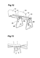
- FIG. 12 is a perspective bottom view of two seating units connected together
- FIG. 13 is an enlarged perspective view of the connection between two seating units
- FIG. 14 is a perspective view of a number of seating units according to FIG. 1 stacked one on top of the other;
- FIG. 15 is a different perspective view of the stacked seating units
- FIG. 16 is a perspective view of another embodiment of a seating unit according to this invention.
- FIG. 17 is a plan view of the seating unit according to FIG. 16 ;
- FIG. 18 is a side view of the seating unit according to FIG. 16 ;
- FIG. 19 is a front view of the seating unit according to FIG. 16 ;
- FIG. 20 is a side view of the seating unit according to FIG. 16 ;
- FIG. 21 is a front view of three seating units according to FIG. 16 connected together, with one seating unit in the process of being mounted;
- FIG. 22 is an enlarged view of the sectional part of FIG. 21 ;
- FIG. 23 is a front view of three seating units according to FIG. 16 finally connected together;
- FIG. 24 is an enlarged view of the sectional part of FIG. 23 .
- FIG. 25 is a perspective view of a number of seating units according to FIG. 16 stacked one on top of the other.
- the seating unit shown in FIG. 1 includes a tubular frame 1 formed by an endless bent tube in the embodiment shown.
- the tubular frame 1 in turn includes two first and second tubular portions 3 A and 3 B which are generally horizontal in the working position of the seating unit and which are connected together in the region of one of their ends by means of a loop/a third tubular portion 5 having a rectilinear intermediate portion 7 according to the embodiment shown.
- the first and second tubular portions 3 A, 3 B converge towards one another in the direction towards the loop 5 .
- the first and second tubular portions 3 A and 3 B form an angle ⁇ with the intermediate portion 7 .
- the first and second tubular portions 3 A and 3 B are bent/curved downwards slightly when the seating unit is viewed from the front (see FIG. 2 ). This design will be discussed hereinbelow. It will also be clear from FIG. 2 that the loop 5 is inclined upwards slightly relative to an imaginary horizontal plane towards its free end.
- the tubular frame also includes fourth and fifth tubular portions 9 A and 9 B which are substantially vertical when the seating unit is viewed from the front ( FIG. 2 ).
- One end of the fourth and fifth tubular portions 9 A and 9 B respectively is connected to one or other of the first and second tubular portions 3 A and 3 B respectively.
- the other ends of the fourth and fifth tubular portions 9 A and 9 B are connected together by means of a cross bar/a sixth tubular portion 10 having a rectilinear intermediate portion according to the embodiment shown.
- the cross bar 10 In the working position of the seating unit, the cross bar 10 is designed to bear against a supporting surface, usually a floor.
- FIGS. 5 and 6 In the side view of the seating unit according to this invention (see FIGS. 5 and 6 ), it will be clear that the fourth and fifth tubular portions 9 A, 9 B diverge away from one another in the direction towards the cross bar 10 .
- the tubular frame 1 may be manufactured from a suitable metal/alloy or from a suitable plastic material.
- the seating unit according to this invention also includes a seat 12 which, according to the embodiment shown, includes a seat portion 13 and a back portion 14 , these portions being integral with one another according to the embodiment shown.
- the seat portion 13 is supported by the first and second tubular portions 3 A, 3 B.
- the abovementioned downward bend/curve of the first and second tubular portions 3 A, 3 B means that the seat portion 13 can be given a dished shape, this having a positive effect on seating comfort.
- Each seat 12 is provided with a side portion 20 extending downwardly from the seat portion 13 , this side portion 20 being situated on the same side of the seat portion 13 as the fourth and fifth tubular portions 9 A, 9 B.
- the side portion 20 is provided with an opening 21 , this opening 21 being U-shaped when viewed generally, with the bottom 22 of the U having a substantially greater length than the legs 23 of the U. More precisely, the opening 21 is generally speaking dovetailed, i.e. the legs 23 converge slightly towards one another in a direction away from the seat portion 13 . This is shown in FIG. 6 by the dash-dotted first lines L 1 and by the angles designated ⁇ in FIG. 6 , symbolising that the lines L 1 move closer together in a direction away from the seat portion 13 .
- the angle ⁇ in FIG. 6 corresponds to the angle designated ⁇ in FIG. 4 .
- Auxiliary lines HL 1 and HL 2 have also been drawn in FIG. 6 , the first auxiliary line HL 1 being situated midway between the first lines L 1 and the first auxiliary line HL 1 extending at a right angle to the bottom 22 of the U.
- the second auxiliary line HL 2 extends at a right angle to the first auxiliary line HL 1 .
- the angle ⁇ is the angle between the first lines L 1 and the second auxiliary line HL 2 . The following should apply with respect to the angle ⁇ : 90° ⁇ 94°.
- FIG. 6 also shows how the walls of the side portion 20 defining the legs 23 converge towards one another in a direction away from the seat portion 13 . This is indicated by means of second lines L 2 and the angle ⁇ between the lines L 1 and L 2 . The following should apply with respect to the angle ⁇ : 8° ⁇ 10°.
- FIGS. 7 and 8 Two third lines L 3 , a third auxiliary line HL 3 and a fourth auxiliary line HL 4 are drawn in FIG. 8 .
- the third lines L 3 converge towards one another in a direction under the seat portion 13 .
- the third auxiliary line HL 3 is situated midway between the third lines L 3 and the third auxiliary line HL 3 extends at a right angle to the side portion 20 .
- the fourth auxiliary line HL 4 extends at a right angle to the third auxiliary line HL 3 .
- the third lines L 2 , the third auxiliary line HL 3 and the fourth auxiliary line HL 4 are situated in one common plane.
- the third lines L 3 form an angle ⁇ with the fourth auxiliary line HL 4 , i.e. the same angle ⁇ inserted in FIG. 6 and for which a setpoint range was specified hereinabove.
- FIGS. 9 and 10 show the opening 21 obliquely from below and from the inside of the side portion 20 .
- the wall thickness of the side portion 20 is relatively great and that the side portion 20 is provided on its inside with a retaining means in the form of a recess 24 extending substantially horizontally and between the legs 23 .
- the dimensions of the retaining means/recess 24 are adapted in such a manner that it should be possible for the loop 5 to be received in the retaining means/recess 24 in a satisfactory manner.
- the intermediate portion 7 of the loop 5 of a seating unit should be parallel to the retaining means/recess 24 .
- the loop 5 thus fits into the retaining means/recess 24 in a satisfactory manner.
- the seat 12 is preferably made of a suitable plastic material.
- FIGS. 11A-11C show in diagrammatic form how two seating units according to this invention are connected together.
- two seating units are situated next to one another, although they are separate.
- the right-hand end of the right-hand seating unit is angled upwards slightly so that the loop 5 serving as a connecting means is substantially horizontal, as a result of which the loop 5 can be inserted into the opening 21 in a simple manner.
- the loop 5 has been inserted into the opening 21 to a sufficient extent, the right-hand side of the right-hand seating unit can be angled downwards, resulting in slight separation of the seating units in the plane of the drawing so that the loop 5 should assume the correct final position.
- FIGS. 14 and 15 show how a number of seating units according to this invention can be stacked one inside the other. This offers a clear advantage with respect to the storage of the seating units when they are not in use.
- FIGS. 16-20 show an alternative embodiment of a seating unit according to this invention, in which a characterising feature of the seating unit according to FIGS. 16-20 is that the parts forming part of the seating unit are integral with one another, i.e. the seating unit according to FIGS. 16-20 is formed in one piece.
- the seating unit according to FIGS. 16-20 is preferably made of a suitable plastic material, wherein one conceivable method of manufacturing the seating unit according to FIGS. 16-20 may be injection moulding.
- the seating unit according to FIGS. 16-20 includes a seat 112 which, according to the embodiment shown, includes a seat portion 113 and a back portion 114 , these portions being integral with one another according to the embodiment shown.
- the seat portion 113 is given a dished shape, this having a positive effect on seating comfort.
- a connecting means in the form of a tongue 105 departs from one side of the seat portion 113 and is integral with the seat portion 113 .
- the tongue has a generally tapering shape towards its free end.
- the tongue 105 extends obliquely downwards from the seat portion 113 towards the free end of the tongue 105 .
- the inclination of the tongue relative to a plane parallel to the surface on which the seating unit rests in the effective position is designated ⁇ 2 in FIG. 19 .
- ⁇ 2 is preferably within the range: 13° ⁇ 2 ⁇ 15°.
- a shoulder 106 is provided on the top of the tongue 105 in the region of its free end, the shoulder 106 being situated in the centre of the free end of the tongue 105 .
- the shoulder 106 is preferably integral with the tongue 105 .
- Each seating unit is provided with a side portion 20 extending downwardly from the seat portion 113 , this side portion 120 being situated on one side of the seat portion 113 .
- the side portion 120 extends from the seat portion 113 down to the surface on which the seating unit is supposed to be supported when the seating unit is in the effectively connected position.
- the side portion 120 is integral with the seat portion 113 .
- the side portion extends substantially vertically in the effectively connected position of a seating unit.
- the side portion 120 is provided with an opening 121 , this opening having an oblong rectangular shape when viewed generally.
- the dimensions of the tongue 105 and of the opening 121 are adapted to one another in such a manner that the tongue 105 of one seating unit can be inserted into the opening 121 in the seating unit to which it is to be connected.
- the opening 121 is to this end provided with a recess allowing for the passage of the shoulder 106 when the tongue 105 is inserted into the opening 121 .
- FIGS. 21-24 show in diagrammatic form how two seating units according to FIGS. 16-20 are connected together.
- two seating units are connected together, while a third seating unit is in the process of being connected.
- the tongue 105 has been inserted into the opening 121 , wherein the seating unit to be mounted is thus inclined slightly, i.e. the end situated furthest away from the already mounted seating units is raised slightly.
- FIG. 22 shows in detail how the tongue 105 is oriented in the opening 121 during the mounting phase itself. The principal plane defined by the tongue 105 therefore forms an angle ⁇ 1 with a plane parallel to the plane on which the seating units rest.
- the raised end of the seating unit is lowered so that it rests on the supporting surface.
- the tongue 105 thus assumes the position shown in FIG. 24 , i.e. the shoulder 106 is angled upwardly and is in contact with the underside of the seat portion 113 of the seating unit to which it is to be connected.
- the shoulder 106 is preferably covered in a friction material.
- a recess for receiving the shoulder 106 may be provided on the underside of the seat portion 113 . Looking at FIG. 24 , it will be clear that the shoulder 106 locks the two seating units connected together in such a manner that they cannot be separated in the lateral direction.
- FIG. 25 shows a number of seating units stacked one on top of the other. As each seating unit only “builds” upon the height by the thickness of the corresponding seat portion 113 , an extremely compact unit is obtained upon stacking.
- the seating unit situated at one end of the row of seating units connected together must be provided with a special support for its connecting means 5 ; 105 or it may be conceivable to use a specially designed seating unit which is more like a conventional chair, i.e. which can stand independently on the floor.
- the shape of the tongue 105 may be varied, particularly with respect to the extent to which the tongue tapers towards its free end. A certain tapering is preferred as it facilitates the insertion of the tongue into the opening in the adjacent seating unit.
- the connecting means may also be conceivable according to the invention for the connecting means to be in the form of a loop, but with the same basic shape as the tongue. This therefore results in a weight saving.
- the outermost part of the loop can therefore be covered in a friction material, resulting in an increase in the diameter of the outermost part of the loop and thereby offering the equivalent of a shoulder.
- the seat 12 ; 112 is provided with a back.
- the seat it is conceivable for the seat not to have a back or for the back to be formed by a separate part that can be mounted on the seat.
- the seat is made of a material, e.g. some sort of metal, that may be perceived as cold and hard by certain users, it may be conceivable for the seat to be provided with a shell, e.g. of pressed felt.
Abstract
Description
Claims (7)
Applications Claiming Priority (4)
| Application Number | Priority Date | Filing Date | Title |
|---|---|---|---|
| SE1000189 | 2010-03-01 | ||
| SE1000189-9 | 2010-03-01 | ||
| SE1000189A SE535461C2 (en) | 2010-03-01 | 2010-03-01 | Seat arrangement |
| PCT/SE2011/000036 WO2011108966A1 (en) | 2010-03-01 | 2011-02-24 | Seating device |
Publications (2)
| Publication Number | Publication Date |
|---|---|
| US20120313412A1 US20120313412A1 (en) | 2012-12-13 |
| US9173494B2 true US9173494B2 (en) | 2015-11-03 |
Family
ID=44542431
Family Applications (1)
| Application Number | Title | Priority Date | Filing Date |
|---|---|---|---|
| US13/580,521 Expired - Fee Related US9173494B2 (en) | 2010-03-01 | 2011-02-24 | Seating device |
Country Status (4)
| Country | Link |
|---|---|
| US (1) | US9173494B2 (en) |
| EP (1) | EP2542120B1 (en) |
| SE (1) | SE535461C2 (en) |
| WO (1) | WO2011108966A1 (en) |
Cited By (2)
| Publication number | Priority date | Publication date | Assignee | Title |
|---|---|---|---|---|
| US10021981B1 (en) * | 2017-02-20 | 2018-07-17 | Zhuhai Shichang Metals Ltd. | Molded tray and chair ganging device |
| US10349746B2 (en) | 2017-02-13 | 2019-07-16 | Krueger International, Inc. | Pivoting ganging arms for chairs |
Families Citing this family (2)
| Publication number | Priority date | Publication date | Assignee | Title |
|---|---|---|---|---|
| US9282823B2 (en) * | 2011-05-10 | 2016-03-15 | Aichi Co., Ltd. | Linking mechanism and chair |
| DE202014100124U1 (en) * | 2014-01-13 | 2015-01-15 | Leland International Inc. | Chair with coupling device for linking |
Citations (24)
| Publication number | Priority date | Publication date | Assignee | Title |
|---|---|---|---|---|
| US2990876A (en) * | 1960-03-16 | 1961-07-04 | Brook John Burbige | Chair |
| US3009738A (en) * | 1960-04-18 | 1961-11-21 | Hampden Specialty Products Cor | Chair coupling construction |
| US3123399A (en) * | 1964-03-03 | Fuknituke structure | ||
| US3159425A (en) * | 1962-09-18 | 1964-12-01 | Royalmetal Corp | Stacking and ganging furniture construction |
| US3237984A (en) | 1964-10-19 | 1966-03-01 | American Seating Co | Plastic connector plates for stacking chairs |
| US3402963A (en) | 1967-05-22 | 1968-09-24 | Samsonite Corp | Chair tiering attachments |
| US3600036A (en) * | 1969-07-09 | 1971-08-17 | Miller Herman Inc | Component seating |
| US3614158A (en) * | 1969-12-05 | 1971-10-19 | Tiffany Industries | Chair ganging device |
| US3758155A (en) * | 1972-03-16 | 1973-09-11 | Interlake Inc | Gang chair construction |
| US3826453A (en) * | 1973-02-21 | 1974-07-30 | Shaw Walker Co | Ganging chairs |
| US4154476A (en) | 1978-06-26 | 1979-05-15 | Leif Blodee | Side-folding, ganged seating system |
| US4386804A (en) * | 1981-04-06 | 1983-06-07 | Krueger Metal Products, Inc. | Chair ganging equipment |
| US4400031A (en) | 1981-03-12 | 1983-08-23 | Virco Mfg. Corporation | Interlocking chair |
| US4892352A (en) * | 1987-11-04 | 1990-01-09 | Michael Haywood | Seat |
| US4978168A (en) * | 1989-09-25 | 1990-12-18 | Giancarlo Piretti | Chair having retractable ganging apparatus and cooperating stacking pad |
| US4995668A (en) * | 1990-07-13 | 1991-02-26 | Bashir Zivari | Modular stool |
| US5282669A (en) * | 1992-06-16 | 1994-02-01 | Shelby Williams Industries, Inc. | Ganging mechanism and stacking bar assembly for stacking chairs |
| US5511851A (en) * | 1995-01-09 | 1996-04-30 | Skools Inc | Modular stool |
| US6012773A (en) * | 1997-04-15 | 2000-01-11 | Mauser Office Gmbh | Lecture desk |
| US6733082B1 (en) * | 1999-09-24 | 2004-05-11 | Dant Clayton Corporation | Interlocking stadium seating system |
| DE202007000971U1 (en) | 2007-01-23 | 2007-03-29 | Kusch & Co. Sitzmöbelwerke GmbH & Co. KG | Chair for seating in rows, has frame with operating bars designed as U-shaped, laterally standing back frame stacking supports with distant connecting units, where transverse bars are provided as one-piece with front and rear chair legs |
| US20070227415A1 (en) * | 2006-03-31 | 2007-10-04 | Mike Meiners | Stackable, interlockable furniture modules |
| GB2447508A (en) | 2007-03-16 | 2008-09-17 | Sebastian Kacary | Seating units |
| DE202009007655U1 (en) | 2009-05-29 | 2009-08-13 | Design Ballendat Gmbh | chain chair |
Family Cites Families (1)
| Publication number | Priority date | Publication date | Assignee | Title |
|---|---|---|---|---|
| BE627336A (en) * |
-
2010
- 2010-03-01 SE SE1000189A patent/SE535461C2/en not_active IP Right Cessation
-
2011
- 2011-02-24 EP EP11750983.6A patent/EP2542120B1/en active Active
- 2011-02-24 WO PCT/SE2011/000036 patent/WO2011108966A1/en active Application Filing
- 2011-02-24 US US13/580,521 patent/US9173494B2/en not_active Expired - Fee Related
Patent Citations (24)
| Publication number | Priority date | Publication date | Assignee | Title |
|---|---|---|---|---|
| US3123399A (en) * | 1964-03-03 | Fuknituke structure | ||
| US2990876A (en) * | 1960-03-16 | 1961-07-04 | Brook John Burbige | Chair |
| US3009738A (en) * | 1960-04-18 | 1961-11-21 | Hampden Specialty Products Cor | Chair coupling construction |
| US3159425A (en) * | 1962-09-18 | 1964-12-01 | Royalmetal Corp | Stacking and ganging furniture construction |
| US3237984A (en) | 1964-10-19 | 1966-03-01 | American Seating Co | Plastic connector plates for stacking chairs |
| US3402963A (en) | 1967-05-22 | 1968-09-24 | Samsonite Corp | Chair tiering attachments |
| US3600036A (en) * | 1969-07-09 | 1971-08-17 | Miller Herman Inc | Component seating |
| US3614158A (en) * | 1969-12-05 | 1971-10-19 | Tiffany Industries | Chair ganging device |
| US3758155A (en) * | 1972-03-16 | 1973-09-11 | Interlake Inc | Gang chair construction |
| US3826453A (en) * | 1973-02-21 | 1974-07-30 | Shaw Walker Co | Ganging chairs |
| US4154476A (en) | 1978-06-26 | 1979-05-15 | Leif Blodee | Side-folding, ganged seating system |
| US4400031A (en) | 1981-03-12 | 1983-08-23 | Virco Mfg. Corporation | Interlocking chair |
| US4386804A (en) * | 1981-04-06 | 1983-06-07 | Krueger Metal Products, Inc. | Chair ganging equipment |
| US4892352A (en) * | 1987-11-04 | 1990-01-09 | Michael Haywood | Seat |
| US4978168A (en) * | 1989-09-25 | 1990-12-18 | Giancarlo Piretti | Chair having retractable ganging apparatus and cooperating stacking pad |
| US4995668A (en) * | 1990-07-13 | 1991-02-26 | Bashir Zivari | Modular stool |
| US5282669A (en) * | 1992-06-16 | 1994-02-01 | Shelby Williams Industries, Inc. | Ganging mechanism and stacking bar assembly for stacking chairs |
| US5511851A (en) * | 1995-01-09 | 1996-04-30 | Skools Inc | Modular stool |
| US6012773A (en) * | 1997-04-15 | 2000-01-11 | Mauser Office Gmbh | Lecture desk |
| US6733082B1 (en) * | 1999-09-24 | 2004-05-11 | Dant Clayton Corporation | Interlocking stadium seating system |
| US20070227415A1 (en) * | 2006-03-31 | 2007-10-04 | Mike Meiners | Stackable, interlockable furniture modules |
| DE202007000971U1 (en) | 2007-01-23 | 2007-03-29 | Kusch & Co. Sitzmöbelwerke GmbH & Co. KG | Chair for seating in rows, has frame with operating bars designed as U-shaped, laterally standing back frame stacking supports with distant connecting units, where transverse bars are provided as one-piece with front and rear chair legs |
| GB2447508A (en) | 2007-03-16 | 2008-09-17 | Sebastian Kacary | Seating units |
| DE202009007655U1 (en) | 2009-05-29 | 2009-08-13 | Design Ballendat Gmbh | chain chair |
Non-Patent Citations (1)
| Title |
|---|
| International Search Report, dated Jun. 7, 2011, from corresponding PCT application. |
Cited By (2)
| Publication number | Priority date | Publication date | Assignee | Title |
|---|---|---|---|---|
| US10349746B2 (en) | 2017-02-13 | 2019-07-16 | Krueger International, Inc. | Pivoting ganging arms for chairs |
| US10021981B1 (en) * | 2017-02-20 | 2018-07-17 | Zhuhai Shichang Metals Ltd. | Molded tray and chair ganging device |
Also Published As
| Publication number | Publication date |
|---|---|
| EP2542120B1 (en) | 2019-05-08 |
| WO2011108966A1 (en) | 2011-09-09 |
| US20120313412A1 (en) | 2012-12-13 |
| EP2542120A1 (en) | 2013-01-09 |
| SE535461C2 (en) | 2012-08-14 |
| SE1000189A1 (en) | 2011-09-02 |
| EP2542120A4 (en) | 2013-10-16 |
Similar Documents
| Publication | Publication Date | Title |
|---|---|---|
| US9173494B2 (en) | Seating device | |
| US5863096A (en) | Stackable and laterally interlockable chairs | |
| RU2571023C2 (en) | Seating furniture | |
| US20090072599A1 (en) | Chair | |
| US7770968B2 (en) | Stackable chair | |
| US8152237B2 (en) | Stacking chair | |
| US20150196124A1 (en) | Chair Having A Coupling Unit For Interlinking Purposes | |
| US20080258515A1 (en) | Chair for mechanics | |
| US6749259B2 (en) | Ganging device for stackbar of stackable chair | |
| US10952536B1 (en) | Connecting table system | |
| KR20210000729U (en) | Armrest device of chair | |
| KR100994822B1 (en) | Headrest for chair | |
| CN201727146U (en) | Chair capable of being connected and stacked mutually | |
| JP5656600B2 (en) | Chair | |
| JP6595047B2 (en) | Chair | |
| CN211048864U (en) | Tea drinking stool with adjustable height and angle of V-shaped stool surface | |
| CN220157909U (en) | Chair and leaning piece lifting adjusting mechanism thereof | |
| CN209031600U (en) | Multifunction chair | |
| CN201088299Y (en) | Chair capable of adjusting height | |
| CN217951743U (en) | Embedded hidden television bracket | |
| US11930930B1 (en) | Modular furniture assembly | |
| CN110840132A (en) | Method for adjusting height and angle of V-shaped stool surface of tea drinking stool | |
| CN217218515U (en) | Foldable stand seat that durability is strong | |
| CN217090068U (en) | Module combined furniture | |
| EP0442241A1 (en) | Nesting furniture |
Legal Events
| Date | Code | Title | Description |
|---|---|---|---|
| AS | Assignment |
Owner name: ANDREAS FAHLSTEDT DESIGN, SWEDEN Free format text: ASSIGNMENT OF ASSIGNORS INTEREST;ASSIGNOR:FAHLSTEDT, ANDREAS;REEL/FRAME:028843/0126 Effective date: 20120821 |
|
| FEPP | Fee payment procedure |
Free format text: PAYOR NUMBER ASSIGNED (ORIGINAL EVENT CODE: ASPN); ENTITY STATUS OF PATENT OWNER: SMALL ENTITY |
|
| AS | Assignment |
Owner name: ANDREAS FAHLSTEDT DESIGN, SWEDEN Free format text: CHANGE OF ADDRESS;ASSIGNOR:ANDREAS FAHLSTEDT DESIGN;REEL/FRAME:035886/0549 Effective date: 20140516 |
|
| ZAAA | Notice of allowance and fees due |
Free format text: ORIGINAL CODE: NOA |
|
| ZAAB | Notice of allowance mailed |
Free format text: ORIGINAL CODE: MN/=. |
|
| STCF | Information on status: patent grant |
Free format text: PATENTED CASE |
|
| MAFP | Maintenance fee payment |
Free format text: PAYMENT OF MAINTENANCE FEE, 4TH YR, SMALL ENTITY (ORIGINAL EVENT CODE: M2551); ENTITY STATUS OF PATENT OWNER: SMALL ENTITY Year of fee payment: 4 |
|
| FEPP | Fee payment procedure |
Free format text: MAINTENANCE FEE REMINDER MAILED (ORIGINAL EVENT CODE: REM.); ENTITY STATUS OF PATENT OWNER: SMALL ENTITY |
|
| LAPS | Lapse for failure to pay maintenance fees |
Free format text: PATENT EXPIRED FOR FAILURE TO PAY MAINTENANCE FEES (ORIGINAL EVENT CODE: EXP.); ENTITY STATUS OF PATENT OWNER: SMALL ENTITY |
|
| STCH | Information on status: patent discontinuation |
Free format text: PATENT EXPIRED DUE TO NONPAYMENT OF MAINTENANCE FEES UNDER 37 CFR 1.362 |
|
| FP | Lapsed due to failure to pay maintenance fee |
Effective date: 20231103 |