US9157534B2 - Two-stud diaphragm for diaphragm valves - Google Patents
Two-stud diaphragm for diaphragm valves Download PDFInfo
- Publication number
- US9157534B2 US9157534B2 US13/554,535 US201213554535A US9157534B2 US 9157534 B2 US9157534 B2 US 9157534B2 US 201213554535 A US201213554535 A US 201213554535A US 9157534 B2 US9157534 B2 US 9157534B2
- Authority
- US
- United States
- Prior art keywords
- diaphragm
- weir
- compressor
- fluid
- flow
- Prior art date
- Legal status (The legal status is an assumption and is not a legal conclusion. Google has not performed a legal analysis and makes no representation as to the accuracy of the status listed.)
- Expired - Fee Related, expires
Links
- 239000012530 fluid Substances 0.000 claims abstract description 39
- 238000007789 sealing Methods 0.000 claims abstract description 34
- 230000008878 coupling Effects 0.000 claims description 8
- 238000010168 coupling process Methods 0.000 claims description 8
- 238000005859 coupling reaction Methods 0.000 claims description 8
- 230000006835 compression Effects 0.000 claims description 4
- 238000007906 compression Methods 0.000 claims description 4
- 238000000034 method Methods 0.000 description 11
- 229920001343 polytetrafluoroethylene Polymers 0.000 description 9
- 239000004810 polytetrafluoroethylene Substances 0.000 description 9
- 229920001971 elastomer Polymers 0.000 description 5
- 239000000806 elastomer Substances 0.000 description 5
- 230000007246 mechanism Effects 0.000 description 5
- 239000000835 fiber Substances 0.000 description 3
- 239000002131 composite material Substances 0.000 description 2
- 230000000694 effects Effects 0.000 description 2
- 239000013536 elastomeric material Substances 0.000 description 2
- 230000008569 process Effects 0.000 description 2
- -1 Polytetrafluoroethylene Polymers 0.000 description 1
- 238000007792 addition Methods 0.000 description 1
- 239000011324 bead Substances 0.000 description 1
- 230000005540 biological transmission Effects 0.000 description 1
- 229920002313 fluoropolymer Polymers 0.000 description 1
- 239000004811 fluoropolymer Substances 0.000 description 1
- 230000006872 improvement Effects 0.000 description 1
- 238000009434 installation Methods 0.000 description 1
- 230000014759 maintenance of location Effects 0.000 description 1
- 239000000463 material Substances 0.000 description 1
- 239000012528 membrane Substances 0.000 description 1
- 230000004048 modification Effects 0.000 description 1
- 238000012986 modification Methods 0.000 description 1
- 239000002991 molded plastic Substances 0.000 description 1
- 230000002093 peripheral effect Effects 0.000 description 1
- 230000000717 retained effect Effects 0.000 description 1
- BFKJFAAPBSQJPD-UHFFFAOYSA-N tetrafluoroethene Chemical group FC(F)=C(F)F BFKJFAAPBSQJPD-UHFFFAOYSA-N 0.000 description 1
- 230000007704 transition Effects 0.000 description 1
Images


Classifications
-
- F—MECHANICAL ENGINEERING; LIGHTING; HEATING; WEAPONS; BLASTING
- F16—ENGINEERING ELEMENTS AND UNITS; GENERAL MEASURES FOR PRODUCING AND MAINTAINING EFFECTIVE FUNCTIONING OF MACHINES OR INSTALLATIONS; THERMAL INSULATION IN GENERAL
- F16K—VALVES; TAPS; COCKS; ACTUATING-FLOATS; DEVICES FOR VENTING OR AERATING
- F16K7/00—Diaphragm valves or cut-off apparatus, e.g. with a member deformed, but not moved bodily, to close the passage ; Pinch valves
- F16K7/12—Diaphragm valves or cut-off apparatus, e.g. with a member deformed, but not moved bodily, to close the passage ; Pinch valves with flat, dished, or bowl-shaped diaphragm
- F16K7/126—Diaphragm valves or cut-off apparatus, e.g. with a member deformed, but not moved bodily, to close the passage ; Pinch valves with flat, dished, or bowl-shaped diaphragm the seat being formed on a rib perpendicular to the fluid line
-
- F—MECHANICAL ENGINEERING; LIGHTING; HEATING; WEAPONS; BLASTING
- F16—ENGINEERING ELEMENTS AND UNITS; GENERAL MEASURES FOR PRODUCING AND MAINTAINING EFFECTIVE FUNCTIONING OF MACHINES OR INSTALLATIONS; THERMAL INSULATION IN GENERAL
- F16K—VALVES; TAPS; COCKS; ACTUATING-FLOATS; DEVICES FOR VENTING OR AERATING
- F16K7/00—Diaphragm valves or cut-off apparatus, e.g. with a member deformed, but not moved bodily, to close the passage ; Pinch valves
- F16K7/12—Diaphragm valves or cut-off apparatus, e.g. with a member deformed, but not moved bodily, to close the passage ; Pinch valves with flat, dished, or bowl-shaped diaphragm
- F16K7/14—Diaphragm valves or cut-off apparatus, e.g. with a member deformed, but not moved bodily, to close the passage ; Pinch valves with flat, dished, or bowl-shaped diaphragm arranged to be deformed against a flat seat
- F16K7/16—Diaphragm valves or cut-off apparatus, e.g. with a member deformed, but not moved bodily, to close the passage ; Pinch valves with flat, dished, or bowl-shaped diaphragm arranged to be deformed against a flat seat the diaphragm being mechanically actuated, e.g. by screw-spindle or cam
Definitions
- the present invention relates to a diaphragm valve; and more particularly relates to a weir-type diaphragm valve.
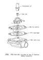
- FIGS. 1 a and 1 b show a diaphragm valve that is known in the art.
- the diaphragm requires two mechanisms to make the valve work in both pressure and vacuum service conditions.
- a closing force, provided through the compressor ( 1 ), and an opening force, applied through the diaphragm stud ( 2 ) can be applied in numerous ways.
- a diaphragm stud is located in the center of the diaphragm.
- the stud and stud retention components create a non-uniformity in the sealing gasket cross section. This non-uniformity interrupts the pressure applied to the contact surface between the weir and diaphragm along the sealing bead of the valve body. This interruption can cause inconsistency of sealing for three reasons:
- peripheral seal of the valve body is independent of the aforementioned weir portion sealing and is made by components omitted from FIGS. 1 a , 1 b.
- the present invention may take the form of apparatus, including a diaphragm valve, that includes a valve body, a diaphragm, a compressor, and at least two studs.
- the valve body has a fluid flow channel and may be configured with a weir portion to control the flow of fluid through the fluid flow channel.
- the diaphragm may be configured to respond to a closing force and to an opening force to make sealing contact with the weir portion to interrupt the flow, or to release the sealing contact with the weir portion to allow the flow.
- the compressor may be configured to apply the closing force or the opening force in order to interrupt or allow the flow.
- the at least two studs may be configured to:
- each stud may be configured with one end embedded within the diaphragm, and with another end having a ball-like member.
- the compressor may be configured with two slots, each slot of the compressor configured to receive and engage a respective ball-like member on a respective end of a respective stud.
- the valve body may be configured with a diaphragm attachment pin; and the diaphragm may be configured with a portion configured with a diaphragm attachment pin aperture to receive and engage the diaphragm attachment pin to provide a slide on attachment and three point constraint to keep each ball in the respective slot of the compressor.
- the apparatus may include a backing cushion arranged between the compressor and the diaphragm, and configured with two apertures for receiving and passing the two studs.
- the backing cushion may be made of an elastomeric material, and may be a composite of an elastomeric material containing a fiber or a fiber mesh.
- the at least two studs may take the form of four studs that are configured to couple the compressor and the diaphragm together; and attach to the diaphragm so as to provide four attachment points, e.g., including two attachment points on the diaphragm on each side of the weir portion.
- the at least two studs may take the form of three studs that are configured to couple the compressor and the diaphragm together; and attach to the diaphragm so as to provide three attachment points, e.g., including two attachment points on the pressure side of the weir portion and one attachment point on the outlet side of the weir portion.
- a weir gasket seal made up of the diaphragm and backing cushion, is uninterrupted by the diaphragm stud connection.
- This allows controlled and even compression of the diaphragm along the entire length of the weir portion of the valve body.
- the technique according to the present invention replaces the single center attachment used in the prior art with two attachment points to either side of the weir gasket seal.
- the attachment mechanism disclosed herein take the form of the two studs embedded within a PTFE diaphragm on one end, and threaded into balls on the other end.
- the attachment mechanism according to the present invention may also take the form of a single piece, e.g., based at least part of design factors or parameters, such as cost and reliability.
- the technique according to the present invention as disclosed herein uses a uniform layer of PTFE and a uniform layer of elastomer between the compressor and the weir valve body.
- the PTFE diaphragm contacts the process fluid and makes the seal to the weir valve body.
- the fiber/elastomeric composite provides membrane strength to resist the high pressure of the process fluid, and provides compliance, resulting in a well distributed seal pressure transmission to the PTFE diaphragm and weir portion of the valve body.
- FIG. 1 a is a cross-section of a known Weir diaphragm valve having traditional PTFE valve sealing components.
- FIG. 1 b is an exploded view of traditional sealing components of a known Weir valve.
- FIG. 2 is an expanded three dimensional view of sealing components in relation to the valve body according to some embodiments of the present invention.
- FIG. 3 is a cross-sectional centerline view (transverse to the direction of flow) of sealing components in relation to the valve body according to some embodiments of the present invention.
- FIG. 4 is a cross-sectional view (parallel to the direction of flow) of sealing components in relation to the valve body according to some embodiments of the present invention.
- FIG. 5 is a view of sealing components according to some embodiments of the present invention.
- FIG. 6 is a cross-sectional view of valve sealing body according to some embodiments of the present invention.
- FIG. 7 is a cross-sectional view (parallel to the direction of flow) of sealing components in relation to the valve body according to some embodiments of the present invention.
- FIGS. 2-4 shows apparatus, in the form of a diaphragm valve, generally indicated as 10 according to some embodiments of the present invention, having a valve body 12 , a compressor 14 , a diaphragm 16 and at least two studs 18 a , 18 b.
- the valve body 12 has a fluid flow channel 12 a configured with a weir portion 12 b to control the flow of fluid through the fluid flow channel 12 a .
- the weir portion 12 b is understood, and known in the art, as a dam-like portion that is raised and extended across the fluid flow channel 12 a , and typically forms part of a Weir-type diaphragm valve.
- the valve body 12 may also be configured with a diaphragm attachment pin 12 c (see FIGS. 5-6 ).
- the compressor 14 may be configured to apply a closing force in order to interrupt the flow of fluid through the fluid flow channel 12 a of the valve body 12 , and also configured to apply an opening force in order to allow the flow of fluid through the fluid flow channel 12 a of the valve body 12 , consistent with that set forth herein.
- the compressor 14 may be coupled to a spindle 20 .
- the compressor 14 has a male coupling member 14 a configured to be received and coupled to a female coupling member 20 a of the spindle 20 .
- the spindle 20 may be configured to receive and apply the closing force and the opening force on the compressor 14 , although the scope of the invention is not intended to be limited to the manner or technique in which the spindle 20 receives or applies the closing force and the opening force.
- the technique for coupling the compressor 14 and spindle 20 is shown by way of example, and the scope of the invention is also not intended to be limited to any particular type or kind of technique for coupling the compressor 14 and spindle 20 together.
- the compressor 14 is shown having a surface 14 b with two slots 14 b 1 , 14 b 2 (see FIG. 5 ).
- the diaphragm 16 is configured to respond to the closing force and make sealing contact with the weir portion 12 b of the valve body 12 to interrupt the flow of fluid through the fluid flow channel 12 a of the valve body 12 .
- the closing force would be a force applied on the spindle 20 directed or pushed downwardly (from the top to bottom of the page), as shown.
- the diaphragm 16 is also configured to respond to the opening force and release the sealing contact with the weir portion 12 b to allow the flow of fluid through the fluid flow channel 12 a of the valve body 12 .
- the opening force would be a force applied on the spindle 20 directed or pulled upwardly (from the bottom to top of the page), as shown.
- the diaphragm 16 is shown as being made of Polytetrafluoroethylene (PTFE), which is a synthetic fluoropolymer of tetrafluoroethylene that is known in the art, although the scope of the invention is intended to include the diaphragm 16 being made from other types or kinds of materials either now known or later developed in the future.
- PTFE Polytetrafluoroethylene
- the two studs 18 a , 18 b are configured to couple the compressor 14 and the diaphragm 16 together; attach to the diaphragm 16 so as to provide attachment points P 1 , P 2 on the diaphragm 16 on each side of the weir portion 12 b , as best shown in FIG.
- each stud 18 a , 18 b provides for non-criticality of stud positions for a reliable seal and improved opening.
- each stud 18 a , 18 b is shown herein as being configured with one end 18 a 1 , 18 b 1 (see FIG. 5 ) embedded within, or forming part of, the diaphragm 16 , and with its other end 18 a 2 , 18 b 2 having a ball-like member configured to be received and engaged in or by a respective slot 14 b 1 , 14 b 2 of the compressor 14 , as best shown in FIGS. 4-7 .
- the two studs 18 a , 18 b have intermediate stem-like portion 18 a 3 , 18 b 3
- the ball-like members may be affixed on the ends 18 a 2 , 18 b 2 , including, e.g., by threading or screwing the ball-like members onto the ends 18 a 2 , 18 b 2 .
- the scope of the invention is intended to include other types or kinds of ways for coupling or affixing the intermediate stem-like portion 18 a 3 , 18 b 3 , and the ball-like members either now known or later developed in the future.
- the ball-like member of the two studs 18 a , 18 b is shown being received in an enlarged portion of the slots 14 b 1 , 14 b 2 and the intermediate stem-like portion 18 a 3 , 18 b 3 of the two studs 18 a , 18 b is configured for sliding into a narrower portion of the slots 14 b 1 , 14 b 2 .
- the ball-like member on each end 18 a 2 , 18 b 2 is wider than the width of the slots 14 b 1 , 14 b 2 so that the ball-like member on each end 18 a 2 , 18 b 2 is retained in and engaged by the narrower portion of the slots 14 b 1 , 14 b 2 once it is slid into the same.
- the diaphragm 16 is configured with a portion 16 a having a diaphragm attachment pin aperture 16 b to receive and engage the diaphragm attachment pin 12 c to provide a slide-on attachment and three point constraint to keep each ball-like member on the ends 18 a 2 , 18 b 2 in the respective slot slots 14 b 1 , 14 b 2 of the compressor 14 .
- the diaphragm valve 10 may also be configured with a backing cushion 22 arranged between the compressor 14 and the diaphragm 16 , and configured with two apertures (one of which is shown as element 22 a in FIG. 1 ) for receiving and passing the two studs 18 a , 18 b.
- FIG. 7 includes a first arrow a 1 pointing to the two studs 18 a , 18 b and the weir portion 12 b and indicating that the stud position can vary according to the present invention; a second arrow a 2 pointing to the two studs 18 a , 18 b and the weir portion 12 b and indicating that there is weir seal independence that results from the configuration according to the present invention; and a third arrow a 3 pointing to the two studs 18 a , 18 b and the weir portion 12 b and indicating that the center and both sides experience a full opening stroke that results from the configuration according to the present invention.
- inventions are also intended to include embodiments having more than two studs.
- the at least two studs 18 a , 18 b take the form of four studs that are configured to couple the compressor 14 and the diaphragm 16 together; and attach to the diaphragm 16 so as to provide four attachment points, e.g., including two attachment points on the diaphragm 16 on each side of the weir portion 12 b .
- the at least two studs 18 a , 18 b take the form of three studs that are configured to couple the compressor 14 and the diaphragm 16 together; and attach to the diaphragm 16 so as to provide three attachment points, e.g., including two attachment points on the pressure side of the weir portion 12 b and one attachment point on the outlet side of the weir portion 12 b.
Landscapes
- Engineering & Computer Science (AREA)
- General Engineering & Computer Science (AREA)
- Mechanical Engineering (AREA)
- Diaphragms And Bellows (AREA)
Abstract
Description
-
- 1) If the stud is too long or adjusted improperly, it can result in over compression of the diaphragm in the center, causing poor valve sealing characteristics and possible damage to the diaphragm.
- 2) If the stud is too short or adjusted improperly, it can result in under compression of the diaphragm in the center, causing poor valve sealing characteristics.
- 3) The transition area between the center seal line under the stud and the side seal line of the compressor may not experience the required seal pressure even if the pressure under the aforementioned components are balanced.
-
- couple the compressor and the diaphragm together,
- attach to the diaphragm so as to provide attachment points on the diaphragm on each side of the weir portion, and
- respond to the closing force or the opening force so that the attachment points on both sides of the weir portion cause the diaphragm to make sealing contact with the weir portion or cause the sealing contact to be released.
-
- a) Ease of proper installation.
- The technique according to the present invention slides into place and is oriented by a passive bonnet constraint, as shown (see
FIG. 5 ).
- The technique according to the present invention slides into place and is oriented by a passive bonnet constraint, as shown (see
- b) Relaxation of assembly dimensional constraints to attachment mechanism.
- The technique according to the present invention does not require tight tolerances on the stud positions to obtain a good seal.
- c) Flow improvement with the same stroke.
Opening the diaphragm at two points to either side of the weir can result in improved flow characteristics over the standard opening mechanisms having the same stroke (spindle vertical motion).
- a) Ease of proper installation.
-
- (1) Use of any form of mechanical attachment which opens the diaphragm without disrupting the centerline gasket uniformity. By way of examples, the attachment may include following:
- (a) Embedding the studs in the PTFE of a laminated diaphragm.
- (b) Embedding the studs between the PTFE and elastomer of a laminated diaphragm.
- (c) Embedding the studs in the elastomer section of a laminated diaphragm.
- (d) Embedding the studs in the elastomer diaphragm.
- (e) Use of other attachment methods away from the weir seal line, such as molded plastic or elastomer knobs or posts made as part of the diaphragm.
- (2) Use of a multitude of attachment points located away from the weir seal line. Example: use four stud with two studs, knobs or posts on each side of the weir.
- (3) Gasket cross section above the weir does not have to be uniform, as manipulation of local gasket thickness to achieve good seal characteristics is also possible using the method of attachment described in this disclosure.
- (1) Use of any form of mechanical attachment which opens the diaphragm without disrupting the centerline gasket uniformity. By way of examples, the attachment may include following:
Claims (8)
Priority Applications (4)
| Application Number | Priority Date | Filing Date | Title |
|---|---|---|---|
| US13/554,535 US9157534B2 (en) | 2012-07-20 | 2012-07-20 | Two-stud diaphragm for diaphragm valves |
| EP13750976.6A EP2875265A1 (en) | 2012-07-20 | 2013-07-18 | Two-stud diaphragm for diaphragm valves |
| PCT/US2013/050985 WO2014015093A1 (en) | 2012-07-20 | 2013-07-18 | Two-stud diaphragm for diaphragm valves |
| MX2015000857A MX2015000857A (en) | 2012-07-20 | 2013-07-18 | Two-stud diaphragm for diaphragm valves. |
Applications Claiming Priority (1)
| Application Number | Priority Date | Filing Date | Title |
|---|---|---|---|
| US13/554,535 US9157534B2 (en) | 2012-07-20 | 2012-07-20 | Two-stud diaphragm for diaphragm valves |
Publications (2)
| Publication Number | Publication Date |
|---|---|
| US20140021392A1 US20140021392A1 (en) | 2014-01-23 |
| US9157534B2 true US9157534B2 (en) | 2015-10-13 |
Family
ID=49003982
Family Applications (1)
| Application Number | Title | Priority Date | Filing Date |
|---|---|---|---|
| US13/554,535 Expired - Fee Related US9157534B2 (en) | 2012-07-20 | 2012-07-20 | Two-stud diaphragm for diaphragm valves |
Country Status (4)
| Country | Link |
|---|---|
| US (1) | US9157534B2 (en) |
| EP (1) | EP2875265A1 (en) |
| MX (1) | MX2015000857A (en) |
| WO (1) | WO2014015093A1 (en) |
Cited By (2)
| Publication number | Priority date | Publication date | Assignee | Title |
|---|---|---|---|---|
| DE102017128229A1 (en) * | 2017-11-29 | 2019-05-29 | Bürkert Werke GmbH & Co. KG | Membrane assembly for a diaphragm valve and diaphragm valve |
| US11391392B2 (en) | 2018-04-23 | 2022-07-19 | Rain Bird Corporation | Valve with reinforcement ports and manually removable scrubber |
Families Citing this family (5)
| Publication number | Priority date | Publication date | Assignee | Title |
|---|---|---|---|---|
| US9366346B2 (en) | 2014-02-28 | 2016-06-14 | Itt Manufacturing Enterprises Llc. | Valve having at least one hourglass studs for coupling to diaphragm and compressor/spindle components |
| SG11202108716UA (en) | 2019-02-20 | 2021-09-29 | Itt Mfg Enterprises Llc | Diaphragm assembly |
| US11236834B2 (en) * | 2019-03-08 | 2022-02-01 | Applied Materials, Inc. | Diaphragm valves and methods of operating same |
| US11236833B2 (en) | 2020-06-26 | 2022-02-01 | Itt Manufacturing Enterprises Llc | Diaphragm valve with plastic diaphragm |
| US20220349488A1 (en) * | 2021-04-30 | 2022-11-03 | Entegris, Inc. | Electrostatic discharge mitigation valve |
Citations (74)
| Publication number | Priority date | Publication date | Assignee | Title |
|---|---|---|---|---|
| US195596A (en) | 1877-09-25 | Improvement in gas-regulators | ||
| GB685935A (en) | 1900-01-01 | |||
| US1609813A (en) | 1926-02-08 | 1926-12-07 | James C Gorman | Power diaphragm pump |
| US1992043A (en) | 1932-06-24 | 1935-02-19 | Saunders Philip Keith | Diaphragm valve |
| US2388989A (en) * | 1944-04-08 | 1945-11-13 | Shriver & Company Inc T | Diaphragm valve |
| US2504057A (en) | 1945-06-22 | 1950-04-11 | Crane Co | Diaphragm valve |
| US2582996A (en) | 1945-03-02 | 1952-01-22 | Milton P Laurent | Seal for gate valve bonnets |
| US2710629A (en) * | 1950-02-03 | 1955-06-14 | Saunders Vaive Company Ltd | Flexible diaphragms |
| US2717757A (en) | 1950-04-07 | 1955-09-13 | Kirkhill Inc | Valve means |
| GB794992A (en) | 1954-06-14 | 1958-05-14 | Grinnell Corp | Diaphragm valves |
| US2872935A (en) | 1955-02-28 | 1959-02-10 | Robert W Kenney | Valve mechanism |
| US3026852A (en) | 1959-05-07 | 1962-03-27 | Kelsey Hayes Co | Booster motor mechanism |
| US3067764A (en) | 1960-04-27 | 1962-12-11 | Ladish Co | Diaphragm valves |
| US3148861A (en) | 1962-06-27 | 1964-09-15 | Hills Mccanna Co | Weir valve |
| US3204919A (en) | 1961-07-31 | 1965-09-07 | Tripoli | Split sleeve control valve |
| GB1011970A (en) | 1962-08-20 | 1965-12-01 | Hills Mccanna Co | Flexible valve diaphragms |
| US3257095A (en) | 1962-12-12 | 1966-06-21 | Chester A Siver | Valve construction particularly packed or sealed |
| GB1080902A (en) | 1963-10-14 | 1967-08-31 | Grinnell Corp | Diaphragm valve |
| US3349795A (en) | 1964-04-22 | 1967-10-31 | Ngk Insulators Ltd | Diaphragm valve including a snap ring connection |
| US3521667A (en) | 1968-01-22 | 1970-07-28 | Fisher Governor Co | Control valve |
| US3561480A (en) | 1968-05-27 | 1971-02-09 | Wayne K Fairchild | Fluid mixing apparatus |
| US3631882A (en) | 1970-01-29 | 1972-01-04 | Grinnell Corp | Diaphragm valve |
| IL35178A (en) | 1969-08-29 | 1973-04-30 | Hayday Valve And Equipment Co | Valves |
| US3811649A (en) * | 1972-07-20 | 1974-05-21 | Resistoflex Corp | Constrictable tube valve with plural wall tube |
| US3982729A (en) | 1974-03-14 | 1976-09-28 | Kerotest Manufacturing Corporation | Back-up seal for diaphragm valve |
| US4014514A (en) | 1975-06-27 | 1977-03-29 | Hills-Mccanna Company | High pressure diaphragm valve |
| US4026513A (en) * | 1975-11-06 | 1977-05-31 | Grove Valve And Regulator Company | Pilot valve |
| US4077605A (en) | 1975-12-11 | 1978-03-07 | Kutz Hugo Joseph | Sealed cartridge valve assembly |
| US4214604A (en) | 1978-02-06 | 1980-07-29 | Rumsey Rollin D | Straight through flow diaphragm valve structures |
| US4231549A (en) | 1978-12-11 | 1980-11-04 | Kerotest Manufacturing Corp. | Valve stem and valve disc connection for a diaphragm valve |
| EP0023409A1 (en) | 1979-07-28 | 1981-02-04 | Waterfield Engineering Limited | Diaphragm valves |
| US4295485A (en) | 1978-04-26 | 1981-10-20 | Waterfield Engineering Limited | Diaphragm valve |
| EP0099945A1 (en) | 1981-01-16 | 1984-02-08 | Waterfield Engineering Limited | Improvements in or relating to soft seating valves |
| US4452428A (en) | 1981-12-24 | 1984-06-05 | Scaramucci John P | Bonnet locking system for a valve |
| US4498798A (en) | 1983-09-26 | 1985-02-12 | Amsted Industries Incorporated | Locating pin |
| DE3447329A1 (en) | 1984-12-24 | 1986-07-03 | Saunders-Sisto Armaturen S.A., Mersch | Diaphragm valve |
| GB2173882A (en) | 1985-04-11 | 1986-10-22 | Kim Prod Ltd | Diaphragm valve |
| US4746095A (en) | 1987-09-14 | 1988-05-24 | Anderson, Greenwood & Co. | Bonnet lock |
| US4750709A (en) | 1986-05-16 | 1988-06-14 | Nupro Company | Diaphragm valve |
| JPH0193674A (en) | 1987-10-02 | 1989-04-12 | Koganei Seisakusho:Kk | Valve |
| US5029813A (en) | 1990-08-06 | 1991-07-09 | Fisher Controls International, Inc. | Diaphragm stem seal attachment |
| US5295662A (en) | 1991-08-26 | 1994-03-22 | Masako Kiyohara | Fluid flow-controller with improved diaphragm |
| WO1995000782A1 (en) | 1993-06-17 | 1995-01-05 | Baecklund Ingvar | Diaphragm valve |
| US5411350A (en) | 1993-11-03 | 1995-05-02 | Loctite Corporation | Quick connect/disconnect device, and dispensing apparatus comprising same |
| US5551477A (en) | 1994-07-08 | 1996-09-03 | Kabushiki-Kaisha Motoyama Seisakusho | Diaphragm-type flow control valve and manual control valve apparatus |
| US5597184A (en) | 1994-09-30 | 1997-01-28 | High Vacuum Apparatus Mfg., Inc. | Quick release clamp for bonnet and flange of gate valves |
| US5624102A (en) | 1994-10-17 | 1997-04-29 | Fujikin Incorporated | Structure for sealing an inner peripheral portion of a metallic diaphragm |
| WO1997017558A1 (en) | 1995-11-10 | 1997-05-15 | Robovalve Aktiebolag | Diaphragm valve |
| US5669596A (en) | 1995-02-15 | 1997-09-23 | Fujikin Incorporated | Diaphragm valve |
| EP0870957A2 (en) | 1997-04-11 | 1998-10-14 | Georg Fischer Rohrleitungssysteme GmbH | Diaphragm valve |
| US6007045A (en) | 1997-08-14 | 1999-12-28 | Georg Fischer Rohrleitungssysteme Ag | Membrane valve assembly |
| US6056003A (en) | 1997-05-28 | 2000-05-02 | Tetra Laval Holdings & Finance S.A. | Double-seated valve |
| US6123315A (en) | 1995-07-28 | 2000-09-26 | Keller; Myron C. | Apparatus and method for reducing water use |
| US6155535A (en) | 1997-12-09 | 2000-12-05 | Marcilese; Joseph Peter | Diaphragm compression limit stops |
| US6227520B1 (en) | 1999-01-19 | 2001-05-08 | New York Air Brake Corporation | Diaphragm piston valve |
| US6296227B1 (en) | 2000-05-24 | 2001-10-02 | Anthony Manufacturing Corporation Commercial Products Division | Valve assembly with clamp on bonnet |
| EP1138989A2 (en) | 2000-03-31 | 2001-10-04 | Toyo Stainless Steel Industries Co., Ltd. | Diaphragm valve |
| US6443426B1 (en) | 1999-07-07 | 2002-09-03 | Arthur Brenes | Slide lock for vacuum valve |
| JP2004204977A (en) | 2002-12-25 | 2004-07-22 | Fujikin Inc | Fluid controller |
| US6845959B2 (en) | 2001-05-04 | 2005-01-25 | Hydril Company, L.P. | Quick release blowout preventer bonnet |
| US20050045847A1 (en) | 2003-08-25 | 2005-03-03 | Powell Douglas H. | Key operational valve |
| US7059584B2 (en) | 2002-12-10 | 2006-06-13 | Kay Balasubramanian | Diaphragm valve having adjustable closure means |
| US7377483B2 (en) | 2004-09-22 | 2008-05-27 | Kitz Sct Corporation | Diaphragm valve |
| JP2008190546A (en) | 2007-01-31 | 2008-08-21 | Iwai Kikai Kogyo Co Ltd | Diaphragm fixing structure of diaphragm valve |
| EP2064468A1 (en) | 2006-09-18 | 2009-06-03 | Karl Locher | Shut-off valve having a leakage function |
| GB2460227A (en) | 2008-05-19 | 2009-11-25 | Walker & Co James Ltd | Valve diaphragm |
| US7628376B2 (en) | 2004-12-10 | 2009-12-08 | Cdk Corporation | Diaphragm valve |
| US7789012B2 (en) | 2005-04-25 | 2010-09-07 | Aquasyn, Llc | Valve bonnet assembly |
| US7815169B2 (en) | 2006-03-29 | 2010-10-19 | Faster S.P.A. | Quick coupling |
| DE102009023002A1 (en) | 2009-05-28 | 2010-12-02 | G.S. Anderson Gmbh | Diaphragm valve drive |
| WO2011014436A1 (en) | 2009-07-27 | 2011-02-03 | Merck Sharpe & Dohme, Corp. | Diaphragm valve with improved sealing performance and leak detection |
| US20110031427A1 (en) | 2009-08-05 | 2011-02-10 | Itt Manufacturing Enterprises, Inc. | Sealing arrangement for a diaphragm valve |
| US8056578B2 (en) | 2007-01-31 | 2011-11-15 | Moen Incorporated | Valve cartridge with lobular key |
| US20120068102A1 (en) | 2010-09-20 | 2012-03-22 | Richard James Anagnos | Bonnet apparatus to provide live-loading to a seal |
-
2012
- 2012-07-20 US US13/554,535 patent/US9157534B2/en not_active Expired - Fee Related
-
2013
- 2013-07-18 MX MX2015000857A patent/MX2015000857A/en unknown
- 2013-07-18 EP EP13750976.6A patent/EP2875265A1/en not_active Withdrawn
- 2013-07-18 WO PCT/US2013/050985 patent/WO2014015093A1/en active Application Filing
Patent Citations (75)
| Publication number | Priority date | Publication date | Assignee | Title |
|---|---|---|---|---|
| US195596A (en) | 1877-09-25 | Improvement in gas-regulators | ||
| GB685935A (en) | 1900-01-01 | |||
| US1609813A (en) | 1926-02-08 | 1926-12-07 | James C Gorman | Power diaphragm pump |
| US1992043A (en) | 1932-06-24 | 1935-02-19 | Saunders Philip Keith | Diaphragm valve |
| US2388989A (en) * | 1944-04-08 | 1945-11-13 | Shriver & Company Inc T | Diaphragm valve |
| US2582996A (en) | 1945-03-02 | 1952-01-22 | Milton P Laurent | Seal for gate valve bonnets |
| US2504057A (en) | 1945-06-22 | 1950-04-11 | Crane Co | Diaphragm valve |
| US2710629A (en) * | 1950-02-03 | 1955-06-14 | Saunders Vaive Company Ltd | Flexible diaphragms |
| US2717757A (en) | 1950-04-07 | 1955-09-13 | Kirkhill Inc | Valve means |
| GB794992A (en) | 1954-06-14 | 1958-05-14 | Grinnell Corp | Diaphragm valves |
| US2872935A (en) | 1955-02-28 | 1959-02-10 | Robert W Kenney | Valve mechanism |
| US3026852A (en) | 1959-05-07 | 1962-03-27 | Kelsey Hayes Co | Booster motor mechanism |
| US3067764A (en) | 1960-04-27 | 1962-12-11 | Ladish Co | Diaphragm valves |
| US3204919A (en) | 1961-07-31 | 1965-09-07 | Tripoli | Split sleeve control valve |
| US3148861A (en) | 1962-06-27 | 1964-09-15 | Hills Mccanna Co | Weir valve |
| GB1011970A (en) | 1962-08-20 | 1965-12-01 | Hills Mccanna Co | Flexible valve diaphragms |
| US3257095A (en) | 1962-12-12 | 1966-06-21 | Chester A Siver | Valve construction particularly packed or sealed |
| GB1080902A (en) | 1963-10-14 | 1967-08-31 | Grinnell Corp | Diaphragm valve |
| US3349795A (en) | 1964-04-22 | 1967-10-31 | Ngk Insulators Ltd | Diaphragm valve including a snap ring connection |
| US3521667A (en) | 1968-01-22 | 1970-07-28 | Fisher Governor Co | Control valve |
| US3561480A (en) | 1968-05-27 | 1971-02-09 | Wayne K Fairchild | Fluid mixing apparatus |
| IL35178A (en) | 1969-08-29 | 1973-04-30 | Hayday Valve And Equipment Co | Valves |
| US3631882A (en) | 1970-01-29 | 1972-01-04 | Grinnell Corp | Diaphragm valve |
| US3811649A (en) * | 1972-07-20 | 1974-05-21 | Resistoflex Corp | Constrictable tube valve with plural wall tube |
| US3982729A (en) | 1974-03-14 | 1976-09-28 | Kerotest Manufacturing Corporation | Back-up seal for diaphragm valve |
| US4014514A (en) | 1975-06-27 | 1977-03-29 | Hills-Mccanna Company | High pressure diaphragm valve |
| US4026513A (en) * | 1975-11-06 | 1977-05-31 | Grove Valve And Regulator Company | Pilot valve |
| US4077605A (en) | 1975-12-11 | 1978-03-07 | Kutz Hugo Joseph | Sealed cartridge valve assembly |
| US4214604A (en) | 1978-02-06 | 1980-07-29 | Rumsey Rollin D | Straight through flow diaphragm valve structures |
| US4295485A (en) | 1978-04-26 | 1981-10-20 | Waterfield Engineering Limited | Diaphragm valve |
| US4231549A (en) | 1978-12-11 | 1980-11-04 | Kerotest Manufacturing Corp. | Valve stem and valve disc connection for a diaphragm valve |
| EP0023409A1 (en) | 1979-07-28 | 1981-02-04 | Waterfield Engineering Limited | Diaphragm valves |
| EP0099945A1 (en) | 1981-01-16 | 1984-02-08 | Waterfield Engineering Limited | Improvements in or relating to soft seating valves |
| US4452428A (en) | 1981-12-24 | 1984-06-05 | Scaramucci John P | Bonnet locking system for a valve |
| US4498798A (en) | 1983-09-26 | 1985-02-12 | Amsted Industries Incorporated | Locating pin |
| DE3447329A1 (en) | 1984-12-24 | 1986-07-03 | Saunders-Sisto Armaturen S.A., Mersch | Diaphragm valve |
| GB2173882A (en) | 1985-04-11 | 1986-10-22 | Kim Prod Ltd | Diaphragm valve |
| US4750709A (en) | 1986-05-16 | 1988-06-14 | Nupro Company | Diaphragm valve |
| US4746095A (en) | 1987-09-14 | 1988-05-24 | Anderson, Greenwood & Co. | Bonnet lock |
| JPH0193674A (en) | 1987-10-02 | 1989-04-12 | Koganei Seisakusho:Kk | Valve |
| US5029813A (en) | 1990-08-06 | 1991-07-09 | Fisher Controls International, Inc. | Diaphragm stem seal attachment |
| US5295662A (en) | 1991-08-26 | 1994-03-22 | Masako Kiyohara | Fluid flow-controller with improved diaphragm |
| WO1995000782A1 (en) | 1993-06-17 | 1995-01-05 | Baecklund Ingvar | Diaphragm valve |
| US5411350A (en) | 1993-11-03 | 1995-05-02 | Loctite Corporation | Quick connect/disconnect device, and dispensing apparatus comprising same |
| US5551477A (en) | 1994-07-08 | 1996-09-03 | Kabushiki-Kaisha Motoyama Seisakusho | Diaphragm-type flow control valve and manual control valve apparatus |
| US5597184A (en) | 1994-09-30 | 1997-01-28 | High Vacuum Apparatus Mfg., Inc. | Quick release clamp for bonnet and flange of gate valves |
| US5624102A (en) | 1994-10-17 | 1997-04-29 | Fujikin Incorporated | Structure for sealing an inner peripheral portion of a metallic diaphragm |
| US5669596A (en) | 1995-02-15 | 1997-09-23 | Fujikin Incorporated | Diaphragm valve |
| US6123315A (en) | 1995-07-28 | 2000-09-26 | Keller; Myron C. | Apparatus and method for reducing water use |
| WO1997017558A1 (en) | 1995-11-10 | 1997-05-15 | Robovalve Aktiebolag | Diaphragm valve |
| EP0870957A2 (en) | 1997-04-11 | 1998-10-14 | Georg Fischer Rohrleitungssysteme GmbH | Diaphragm valve |
| US6056003A (en) | 1997-05-28 | 2000-05-02 | Tetra Laval Holdings & Finance S.A. | Double-seated valve |
| US6007045A (en) | 1997-08-14 | 1999-12-28 | Georg Fischer Rohrleitungssysteme Ag | Membrane valve assembly |
| US6155535A (en) | 1997-12-09 | 2000-12-05 | Marcilese; Joseph Peter | Diaphragm compression limit stops |
| US6227520B1 (en) | 1999-01-19 | 2001-05-08 | New York Air Brake Corporation | Diaphragm piston valve |
| US6443426B1 (en) | 1999-07-07 | 2002-09-03 | Arthur Brenes | Slide lock for vacuum valve |
| EP1138989A2 (en) | 2000-03-31 | 2001-10-04 | Toyo Stainless Steel Industries Co., Ltd. | Diaphragm valve |
| US6296227B1 (en) | 2000-05-24 | 2001-10-02 | Anthony Manufacturing Corporation Commercial Products Division | Valve assembly with clamp on bonnet |
| US6845959B2 (en) | 2001-05-04 | 2005-01-25 | Hydril Company, L.P. | Quick release blowout preventer bonnet |
| US7059584B2 (en) | 2002-12-10 | 2006-06-13 | Kay Balasubramanian | Diaphragm valve having adjustable closure means |
| JP2004204977A (en) | 2002-12-25 | 2004-07-22 | Fujikin Inc | Fluid controller |
| US20050045847A1 (en) | 2003-08-25 | 2005-03-03 | Powell Douglas H. | Key operational valve |
| US7377483B2 (en) | 2004-09-22 | 2008-05-27 | Kitz Sct Corporation | Diaphragm valve |
| US7628376B2 (en) | 2004-12-10 | 2009-12-08 | Cdk Corporation | Diaphragm valve |
| US7789012B2 (en) | 2005-04-25 | 2010-09-07 | Aquasyn, Llc | Valve bonnet assembly |
| US7815169B2 (en) | 2006-03-29 | 2010-10-19 | Faster S.P.A. | Quick coupling |
| EP2064468A1 (en) | 2006-09-18 | 2009-06-03 | Karl Locher | Shut-off valve having a leakage function |
| JP2008190546A (en) | 2007-01-31 | 2008-08-21 | Iwai Kikai Kogyo Co Ltd | Diaphragm fixing structure of diaphragm valve |
| US8056578B2 (en) | 2007-01-31 | 2011-11-15 | Moen Incorporated | Valve cartridge with lobular key |
| GB2460227A (en) | 2008-05-19 | 2009-11-25 | Walker & Co James Ltd | Valve diaphragm |
| DE102009023002A1 (en) | 2009-05-28 | 2010-12-02 | G.S. Anderson Gmbh | Diaphragm valve drive |
| US20120061597A1 (en) | 2009-05-28 | 2012-03-15 | Alfa Laval Corporate Ab | Diaphragm valve drive |
| WO2011014436A1 (en) | 2009-07-27 | 2011-02-03 | Merck Sharpe & Dohme, Corp. | Diaphragm valve with improved sealing performance and leak detection |
| US20110031427A1 (en) | 2009-08-05 | 2011-02-10 | Itt Manufacturing Enterprises, Inc. | Sealing arrangement for a diaphragm valve |
| US20120068102A1 (en) | 2010-09-20 | 2012-03-22 | Richard James Anagnos | Bonnet apparatus to provide live-loading to a seal |
Non-Patent Citations (7)
| Title |
|---|
| 1 page DE102009023002 English Language Abstract. |
| 1 pg DE3447329 English Language Abstract. |
| 1 pg EP0870957 English Language Abstract. |
| 1 pg JP2008190546 English Language Abstract. |
| 2 pgs JP2004204977 English Language Abstract. |
| 2 pgs. JPH0193674 English Language Abstract. |
| English Language Abstract WO2008034686 (1 page), Jun. 3, 2009. |
Cited By (3)
| Publication number | Priority date | Publication date | Assignee | Title |
|---|---|---|---|---|
| DE102017128229A1 (en) * | 2017-11-29 | 2019-05-29 | Bürkert Werke GmbH & Co. KG | Membrane assembly for a diaphragm valve and diaphragm valve |
| US11112031B2 (en) | 2017-11-29 | 2021-09-07 | Buerkert Werke Gmbh & Co. Kg | Diaphragm assembly for a diaphragm valve, and diaphragm valve |
| US11391392B2 (en) | 2018-04-23 | 2022-07-19 | Rain Bird Corporation | Valve with reinforcement ports and manually removable scrubber |
Also Published As
| Publication number | Publication date |
|---|---|
| MX2015000857A (en) | 2015-03-11 |
| US20140021392A1 (en) | 2014-01-23 |
| WO2014015093A1 (en) | 2014-01-23 |
| EP2875265A1 (en) | 2015-05-27 |
Similar Documents
| Publication | Publication Date | Title |
|---|---|---|
| US9157534B2 (en) | Two-stud diaphragm for diaphragm valves | |
| US9046182B2 (en) | Check valve | |
| US8365766B2 (en) | Observation valve structure | |
| US9115820B2 (en) | Fluidic control element with rounded shaft | |
| CN113646562A (en) | Diaphragm and diaphragm valve | |
| US9228673B2 (en) | Flow regulating device | |
| EP2971897B1 (en) | Pressure relief valve assembly | |
| US20140034154A1 (en) | Valve Assembly | |
| US20150323092A1 (en) | Fluid controller actuator | |
| US10233917B2 (en) | Structure for securing diaphragm, and diaphragm pump and valve device equipped with the same | |
| KR101375824B1 (en) | Check valve | |
| US9366346B2 (en) | Valve having at least one hourglass studs for coupling to diaphragm and compressor/spindle components | |
| US20140000731A1 (en) | Flow Control Valve Assemblies with Check Valves | |
| US20150219232A1 (en) | Membrane style excess flow valve | |
| US8651139B2 (en) | Valve | |
| KR20170086866A (en) | Reducing valve | |
| EP3315836A1 (en) | Valve assembly with anti-extrusion valve seat | |
| US11959564B2 (en) | Valve seat assembly | |
| JP7320836B2 (en) | ball valve | |
| CN219345503U (en) | Aseptic diaphragm type single seat valve structure | |
| US9562624B2 (en) | Valve strip retainer assembly | |
| CN106861011B (en) | A kind of oxygen flush valve | |
| CN103542116B (en) | A kind of soft sealing gate valve | |
| CN201723754U (en) | Gate valve seat fixing structure | |
| KR20170042780A (en) | Changeover valve |
Legal Events
| Date | Code | Title | Description |
|---|---|---|---|
| AS | Assignment |
Owner name: ITT MANUFACTURING ENTERPRISES LLC., DELAWARE Free format text: ASSIGNMENT OF ASSIGNORS INTEREST;ASSIGNOR:MATALON, LOUIS E.;REEL/FRAME:029055/0348 Effective date: 20120910 |
|
| STCF | Information on status: patent grant |
Free format text: PATENTED CASE |
|
| MAFP | Maintenance fee payment |
Free format text: PAYMENT OF MAINTENANCE FEE, 4TH YEAR, LARGE ENTITY (ORIGINAL EVENT CODE: M1551); ENTITY STATUS OF PATENT OWNER: LARGE ENTITY Year of fee payment: 4 |
|
| FEPP | Fee payment procedure |
Free format text: MAINTENANCE FEE REMINDER MAILED (ORIGINAL EVENT CODE: REM.); ENTITY STATUS OF PATENT OWNER: LARGE ENTITY |
|
| LAPS | Lapse for failure to pay maintenance fees |
Free format text: PATENT EXPIRED FOR FAILURE TO PAY MAINTENANCE FEES (ORIGINAL EVENT CODE: EXP.); ENTITY STATUS OF PATENT OWNER: LARGE ENTITY |
|
| STCH | Information on status: patent discontinuation |
Free format text: PATENT EXPIRED DUE TO NONPAYMENT OF MAINTENANCE FEES UNDER 37 CFR 1.362 |
|
| FP | Lapsed due to failure to pay maintenance fee |
Effective date: 20231013 |