US9153223B2 - Noise reduction device - Google Patents
Noise reduction device Download PDFInfo
- Publication number
- US9153223B2 US9153223B2 US13/707,483 US201213707483A US9153223B2 US 9153223 B2 US9153223 B2 US 9153223B2 US 201213707483 A US201213707483 A US 201213707483A US 9153223 B2 US9153223 B2 US 9153223B2
- Authority
- US
- United States
- Prior art keywords
- noise
- control
- noise reduction
- residual sound
- residual
- Prior art date
- Legal status (The legal status is an assumption and is not a legal conclusion. Google has not performed a legal analysis and makes no representation as to the accuracy of the status listed.)
- Active, expires
Links
Images


Classifications
-
- G—PHYSICS
- G10—MUSICAL INSTRUMENTS; ACOUSTICS
- G10K—SOUND-PRODUCING DEVICES; METHODS OR DEVICES FOR PROTECTING AGAINST, OR FOR DAMPING, NOISE OR OTHER ACOUSTIC WAVES IN GENERAL; ACOUSTICS NOT OTHERWISE PROVIDED FOR
- G10K11/00—Methods or devices for transmitting, conducting or directing sound in general; Methods or devices for protecting against, or for damping, noise or other acoustic waves in general
- G10K11/16—Methods or devices for protecting against, or for damping, noise or other acoustic waves in general
- G10K11/175—Methods or devices for protecting against, or for damping, noise or other acoustic waves in general using interference effects; Masking sound
- G10K11/178—Methods or devices for protecting against, or for damping, noise or other acoustic waves in general using interference effects; Masking sound by electro-acoustically regenerating the original acoustic waves in anti-phase
- G10K11/1785—Methods, e.g. algorithms; Devices
- G10K11/17857—Geometric disposition, e.g. placement of microphones
-
- G—PHYSICS
- G10—MUSICAL INSTRUMENTS; ACOUSTICS
- G10K—SOUND-PRODUCING DEVICES; METHODS OR DEVICES FOR PROTECTING AGAINST, OR FOR DAMPING, NOISE OR OTHER ACOUSTIC WAVES IN GENERAL; ACOUSTICS NOT OTHERWISE PROVIDED FOR
- G10K11/00—Methods or devices for transmitting, conducting or directing sound in general; Methods or devices for protecting against, or for damping, noise or other acoustic waves in general
- G10K11/002—Devices for damping, suppressing, obstructing or conducting sound in acoustic devices
-
- G—PHYSICS
- G10—MUSICAL INSTRUMENTS; ACOUSTICS
- G10K—SOUND-PRODUCING DEVICES; METHODS OR DEVICES FOR PROTECTING AGAINST, OR FOR DAMPING, NOISE OR OTHER ACOUSTIC WAVES IN GENERAL; ACOUSTICS NOT OTHERWISE PROVIDED FOR
- G10K11/00—Methods or devices for transmitting, conducting or directing sound in general; Methods or devices for protecting against, or for damping, noise or other acoustic waves in general
- G10K11/16—Methods or devices for protecting against, or for damping, noise or other acoustic waves in general
- G10K11/175—Methods or devices for protecting against, or for damping, noise or other acoustic waves in general using interference effects; Masking sound
- G10K11/178—Methods or devices for protecting against, or for damping, noise or other acoustic waves in general using interference effects; Masking sound by electro-acoustically regenerating the original acoustic waves in anti-phase
- G10K11/1785—Methods, e.g. algorithms; Devices
- G10K11/17853—Methods, e.g. algorithms; Devices of the filter
- G10K11/17854—Methods, e.g. algorithms; Devices of the filter the filter being an adaptive filter
-
- G—PHYSICS
- G10—MUSICAL INSTRUMENTS; ACOUSTICS
- G10K—SOUND-PRODUCING DEVICES; METHODS OR DEVICES FOR PROTECTING AGAINST, OR FOR DAMPING, NOISE OR OTHER ACOUSTIC WAVES IN GENERAL; ACOUSTICS NOT OTHERWISE PROVIDED FOR
- G10K11/00—Methods or devices for transmitting, conducting or directing sound in general; Methods or devices for protecting against, or for damping, noise or other acoustic waves in general
- G10K11/16—Methods or devices for protecting against, or for damping, noise or other acoustic waves in general
- G10K11/175—Methods or devices for protecting against, or for damping, noise or other acoustic waves in general using interference effects; Masking sound
- G10K11/178—Methods or devices for protecting against, or for damping, noise or other acoustic waves in general using interference effects; Masking sound by electro-acoustically regenerating the original acoustic waves in anti-phase
- G10K11/1787—General system configurations
- G10K11/17879—General system configurations using both a reference signal and an error signal
- G10K11/17881—General system configurations using both a reference signal and an error signal the reference signal being an acoustic signal, e.g. recorded with a microphone
-
- G—PHYSICS
- G10—MUSICAL INSTRUMENTS; ACOUSTICS
- G10K—SOUND-PRODUCING DEVICES; METHODS OR DEVICES FOR PROTECTING AGAINST, OR FOR DAMPING, NOISE OR OTHER ACOUSTIC WAVES IN GENERAL; ACOUSTICS NOT OTHERWISE PROVIDED FOR
- G10K2210/00—Details of active noise control [ANC] covered by G10K11/178 but not provided for in any of its subgroups
- G10K2210/10—Applications
- G10K2210/128—Vehicles
- G10K2210/1281—Aircraft, e.g. spacecraft, airplane or helicopter
-
- G—PHYSICS
- G10—MUSICAL INSTRUMENTS; ACOUSTICS
- G10K—SOUND-PRODUCING DEVICES; METHODS OR DEVICES FOR PROTECTING AGAINST, OR FOR DAMPING, NOISE OR OTHER ACOUSTIC WAVES IN GENERAL; ACOUSTICS NOT OTHERWISE PROVIDED FOR
- G10K2210/00—Details of active noise control [ANC] covered by G10K11/178 but not provided for in any of its subgroups
- G10K2210/10—Applications
- G10K2210/128—Vehicles
- G10K2210/1283—Trains, trams or the like
-
- G—PHYSICS
- G10—MUSICAL INSTRUMENTS; ACOUSTICS
- G10K—SOUND-PRODUCING DEVICES; METHODS OR DEVICES FOR PROTECTING AGAINST, OR FOR DAMPING, NOISE OR OTHER ACOUSTIC WAVES IN GENERAL; ACOUSTICS NOT OTHERWISE PROVIDED FOR
- G10K2210/00—Details of active noise control [ANC] covered by G10K11/178 but not provided for in any of its subgroups
- G10K2210/30—Means
- G10K2210/321—Physical
- G10K2210/3211—Active mounts for vibrating structures with means to actively suppress the vibration, e.g. for vehicles
-
- G—PHYSICS
- G10—MUSICAL INSTRUMENTS; ACOUSTICS
- G10K—SOUND-PRODUCING DEVICES; METHODS OR DEVICES FOR PROTECTING AGAINST, OR FOR DAMPING, NOISE OR OTHER ACOUSTIC WAVES IN GENERAL; ACOUSTICS NOT OTHERWISE PROVIDED FOR
- G10K2210/00—Details of active noise control [ANC] covered by G10K11/178 but not provided for in any of its subgroups
- G10K2210/30—Means
- G10K2210/321—Physical
- G10K2210/3221—Headrests, seats or the like, for personal ANC systems
-
- H—ELECTRICITY
- H04—ELECTRIC COMMUNICATION TECHNIQUE
- H04R—LOUDSPEAKERS, MICROPHONES, GRAMOPHONE PICK-UPS OR LIKE ACOUSTIC ELECTROMECHANICAL TRANSDUCERS; DEAF-AID SETS; PUBLIC ADDRESS SYSTEMS
- H04R5/00—Stereophonic arrangements
- H04R5/02—Spatial or constructional arrangements of loudspeakers
- H04R5/023—Spatial or constructional arrangements of loudspeakers in a chair, pillow
Definitions
- the technology disclosed herein relates to a noise reduction device used in a seat in a sealed structure such as an aircraft or a railway car.
- the utilized space becomes a kind of sealed structure, and if there is a noise source inside or outside the utilized space, the users of the space are stuck in a noisy environment.
- the main noise sources are noise from the machinery that generates the aircraft's thrust, such as propellers or engines, and wind noise as the aircraft nose and wings slice through the air during flight. Therefore, noise inside the cabin can be uncomfortable for the passengers, and also makes it harder to hear announcements and so forth, so there is a great need for improvement in this area.
- This noise reduction device comprises a microphone that detects noise generated from a noise source, a controller that inverts the phase of and amplifies the output signal of the microphone, and a speaker that converts the output signal of the controller into sound.
- the microphone or speaker in Patent WO2009/078147 and Japanese Laid-Open Patent Application H7-160275 is disposed on the seat surface or inside the seat on which the user sits. Therefore, if the user uses a pillow while napping, for example, the pillow may hide the microphone or speaker.
- the microphone or speaker is particularly prone to being hidden by the pillow when the user is in a recumbent state in a seat that has a reclining mechanism.
- a noise reduction device disclosed herein is used along with a shell that envelops at least part of a seat capable of supporting a user in a substantially lying posture.
- the noise reduction device includes a noise controller, a control sound output component and a residual sound detector.
- the noise controller is configured to produce a control sound signal for canceling out noise.
- the control sound output component is configured to output a control sound based on the control sound signal produced by the noise controller.
- the residual sound detector is configured to detect a residual sound produced by superposition of noise and the control sound outputted from the control sound output component.
- the control sound output component and the residual sound detector are housed in the shell.
- the control sound output component and the residual sound detector are away from a rear face of the seat.
- noise can be accurately attenuated.
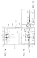
- FIG. 1A , FIG. 1B and FIG. 1C are diagrams illustrating the basic principle whereby noise is reduced in a conventional noise reduction device
- FIG. 2 is a block diagram of the basis circuit configuration of a conventional noise reduction device
- FIG. 3 is a block diagram of the noise reduction device pertaining to an embodiment
- FIG. 4A and FIG. 4B are simulation diagrams for verifying the noise reduction effect of the noise reduction device pertaining to an embodiment
- FIG. 5A and FIG. 5B are experiment diagrams for verifying the noise reduction effect of the noise reduction device pertaining to an embodiment
- FIG. 6A and FIG. 6B are experiment diagrams for verifying the noise reduction effect of the noise reduction device pertaining to an embodiment
- FIG. 7A , FIG. 7B and FIG. 7C are diagrams of the configuration of the noise reduction device pertaining to an embodiment
- FIG. 8 is a diagram illustrating the action of the noise reduction device pertaining to an embodiment
- FIG. 9A , FIG. 9B and FIG. 9C are diagrams of the configuration of the noise reduction device pertaining to another embodiment.
- FIG. 10A and FIG. 10B are diagrams of the configuration of the noise reduction device pertaining to another embodiment.
- FIGS. 1 and 2 the basic principle by which noise is reduced will be described through reference to FIGS. 1 and 2 .
- the noise reduction device 10 shown in FIGS. 1 and 2 is depicted for the purpose of illustrating the basic principle by which noise is reduced, and shows a conventional configuration.
- the configuration of the noise reduction device 100 pertaining to this embodiment will be described later, through reference to FIGS. 3 to 10 .
- FIG. 1A is a front view of an aircraft seat 600 in which the conventional noise reduction device 10 has been installed.
- FIG. 1B is a side view of the seat 600 .
- FIG. 1C is a rear view of the seat 600 .
- FIG. 2 is a block diagram of the basis circuit configuration of the conventional noise reduction device 10 built into the seat 600 .
- the noise reduction device 10 comprises noise detecting microphones 101 to 120 , control speakers 401 to 404 , and residual sound detecting microphones 501 and 502 .
- the noise detecting microphones 101 to 120 detect noise coming from the outside, so they are installed on the outside of the seat 600 .
- the control speakers 401 to 404 are installed at positions that are at substantially the same height as the ears of a user (passenger) A on the inside of the seat 600 .
- the residual sound detecting microphones 501 and 502 are installed, for example, on the ears (control points) of the user A.
- the noise reduction device 10 comprises adaptive filters 201 - 1 to 220 - 1 , 201 - 2 to 220 - 2 , 201 - 3 to 220 - 3 , and 201 - 4 to 220 - 4 , and adders 301 to 304 .
- Noise detected by the noise detecting microphone 101 is outputted as a noise signal to the adaptive filters 201 - 1 to 201 - 4 .
- Noise detected by the noise detecting microphone 102 is outputted as a noise signal to the adaptive filters 202 - 1 to 202 - 4 (not shown).
- noise detected by the noise detecting microphones 103 to 120 is outputted to the adaptive filters 203 (not shown) to 220 .
- a transmission function from the control speaker 401 to the residual sound detecting microphone 501 , and a transmission function from the control speaker 401 to the residual sound detecting microphone 502 are preset by filtered-X_LMS method in the adaptive filter 201 - 1 .
- the adaptive filter 201 - 1 uses the preset transmission functions to update the filter coefficient of this filter so that the residual sound signals from the residual sound detecting microphones 501 and 502 are collectively minimized.
- the residual sound detecting microphones 501 and 502 are installed at control points, and detect noise from a noise source that reaches a control point, and control sounds from the control speakers 401 to 404 that reach a control point.
- the residual sound detecting microphones 501 and 502 detect that noise reaching a control point is interfering with control sounds from the control speakers 401 to 404 , and detect the difference between the noise and the control sounds as a residual sound signal.
- a transmission function from the control speaker 401 to the residual sound detecting microphone 501 and a transmission function from the control speaker 401 to the residual sound detecting microphone 502 are set in the adaptive filter 202 - 1 (not shown).
- the adaptive filter 202 - 1 uses the preset transmission functions to update the filter coefficient of this filter so that the residual sound signals from the residual sound detecting microphones 501 and 502 are collectively minimized.
- a transmission function from the control speaker 401 to the residual sound detecting microphone 501 and a transmission function from the control speaker 401 to the residual sound detecting microphone 502 are set in the adaptive filter 203 - 1 (not shown).
- the adaptive filter 203 - 1 uses the preset transmission functions to update the filter coefficient of this filter so that the residual sound signals from the residual sound detecting microphones 501 and 502 are collectively minimized.
- a transmission function from the control speaker 402 to the residual sound detecting microphone 501 and a transmission function from the control speaker 402 to the residual sound detecting microphone 502 are set in the adaptive filters 201 - 2 to 220 - 2 .
- the adaptive filters 201 - 2 to 220 - 2 use the preset transmission functions to update the filter coefficient of the respective filters so that the residual sound signals from the residual sound detecting microphones 501 and 502 are collectively minimized.
- a transmission function from the control speaker 403 to the residual sound detecting microphone 501 and a transmission function from the control speaker 403 to the residual sound detecting microphone 502 are set in the adaptive filters 201 - 3 to 220 - 3 .
- the adaptive filters 201 - 3 to 220 - 3 use the preset transmission functions to update the filter coefficient of the respective filters so that the residual sound signals from the residual sound detecting microphones 501 and 502 are collectively minimized.
- a transmission function from the control speaker 404 to the residual sound detecting microphone 501 and a transmission function from the control speaker 404 to the residual sound detecting microphone 502 are set in the adaptive filters 201 - 4 to 220 - 4 .
- the adaptive filters 201 - 4 to 220 - 4 use the preset transmission functions to update the filter coefficient of the respective filters so that the residual sound signals from the residual sound detecting microphones 501 and 502 are collectively minimized.
- the adaptive filters 201 - 1 to 220 - 1 use the updated filter coefficients to perform signal processing on the inputted noise signals, and output the results as control signals to the adder 301 .
- the adder 301 adds up the control signals from the adaptive filters 201 - 1 to 220 - 1 , and outputs the results to the control speaker 401 .
- the control speaker 401 outputs a control sound based on the control signal from the adder 301 , toward the residual sound detecting microphones 501 and 502 , which are control points.
- the adaptive filters 201 - 2 to 220 - 2 use the updated filter coefficients to perform signal processing on the inputted noise signals, and output the results as control signals to the adder 302 .
- the adder 302 adds up the control signals from the adaptive filters 201 - 2 to 220 - 2 , and outputs the results to the control speaker 402 .
- the control speaker 402 outputs a control sound based on the control signal from the adder 302 , toward the residual sound detecting microphones 501 and 502 , which are control points.
- the adaptive filters 201 - 3 to 220 - 3 use the updated filter coefficients to perform signal processing on the inputted noise signals, and output the results as control signals to the adder 303 .
- the adder 303 adds up the control signals from the adaptive filters 201 - 3 to 220 - 3 , and outputs the results to the control speaker 403 .
- the control speaker 403 outputs a control sound based on the control signal from the adder 303 , toward the residual sound detecting microphones 501 and 502 , which are control points.
- the adaptive filters 201 - 4 to 220 - 4 use the updated filter coefficients to perform signal processing on the inputted noise signals, and output the results as control signals to the adder 304 .
- the adder 304 adds up the control signals from the adaptive filters 201 - 4 to 220 - 4 , and outputs the results to the control speaker 404 .
- the control speaker 404 outputs a control sound based on the control signal from the adder 304 , toward the residual sound detecting microphones 501 and 502 , which are control points.
- the update processing of the filter coefficients discussed above allows the noise reduction device 10 installed in the seat 600 to reduce noise that reaches the ears (control points) of the user A.
- a noise reduction effect that is the same as when noise is controlled with adaptive filters can be achieved by performing noise control with just fixed filters having a fixed filter frequency, instead of adaptive filters.
- FIG. 3 is a block diagram of the basic circuit configuration of the noise reduction device 100 in this embodiment.
- the noise reduction device 100 comprises a noise detecting microphone 101 , a noise controller 200 , a control speaker 401 , and a residual sound detecting microphone 501 .
- the various components and their functions will now be described.
- the noise reduction device 100 pertaining to this embodiment comprises two sets of noise detecting microphone, noise controller, control speaker, and residual sound detecting microphone (see FIG. 7 ), but since the paired members have substantially the same configuration, just one set is depicted in the drawings and will be described here.
- the noise detecting microphone 101 is an example of a noise detector that detects noise emitted from a noise source B. More specifically, the noise detecting microphone 101 is a microphone that has the function of detecting noise, converting it into an electrical signal, and outputting this signal.
- the noise controller 200 is an example of a noise controller.
- the noise controller 200 comprises A/D converters 231 and 232 , an adaptive filter 201 , a filter coefficient calculator 233 , and a D/A converter 234 .
- the noise controller 200 controls the control speaker 401 and produces control signals so that the residual sound detected by the residual sound detecting microphone 501 is minimized, based on a residual sound signal from the residual sound detecting microphone 501 and a noise signal from the noise detecting microphone 101 .
- the A/D converter 231 subjects the noise signal from the noise detecting microphone 101 to A/D conversion, and outputs the result to the adaptive filter 201 and the filter coefficient calculator 233 .
- the adaptive filter 201 is an FIR (finite impulse response) filter that is made up of multistage tap and that allows the filter coefficient of each tap to be set as desired.
- FIR finite impulse response
- the detected residual sound signal received from the residual sound detecting microphone 501 is inputted through the A/D converter 232 , along with information received from the noise detecting microphone 101 , to the filter coefficient calculator 233 .
- the filter coefficient calculator 233 adjusts the filter coefficients of the adaptive filter 201 so that this detected residual sound will be minimized.
- a control sound signal is produced so that the phase will be the opposite of that of the noise from the noise source at the location where the residual sound detecting microphone 501 is installed, and this signal is outputted through the D/A converter 234 to the control speaker 401 .
- the control speaker 401 is an example of a control sound output component.
- the control speaker 401 can convert a control sound signal received from the D/A converter 234 into a sound wave and output it.
- the control speaker 401 has the function of emitting a control sound that cancels out noise in the vicinity of the ear of the user A.
- the residual sound detecting microphone 501 is an example of a residual sound detector.
- the residual sound detecting microphone 501 detects sound that has undergone noise reduction as residual sound, and performs feedback on the operating result of the noise reduction device 100 . This allows noise always to be minimized at a location near the ear of the user A even if the noise environment or the like should change.
- the noise reduction device 100 in this embodiment uses the noise detecting microphone 101 to detect noise emitted from a noise source, uses the noise controller 200 to perform signal processing, and outputs a control sound from the control speaker 401 .
- noise is reduced by superposing sound of the inverted phase on noise emitted from a noise source, and emitting the resulting sound at the ears of the user A.
- FIG. 4A shows the simulation conditions.
- L 1 (an example of a first distance) is the distance between the control speaker 401 and the residual sound detecting microphone 501 .
- L 2 (an example of a second distance) is the distance from the control speaker 401 to the ear A- 1 of the user A.
- FIG. 4B shows the noise frequency characteristics at the ear A- 1 of the user.
- the broken line shows the frequency characteristics when noise reduction is off
- the noise amplitude is set to be substantially the same at all locations of the residual sound detecting microphone 501 and the ear A- 1 of the user A.
- FIG. 5A shows the experiment conditions.
- the distance L 1 between the control speaker 401 and the residual sound detecting microphone 501 is 20 cm
- FIG. 5B shows the noise reduction effect here.
- the solid line is the noise reduction effect at the residual sound detecting microphone 501
- the dotted line is the noise reduction effect at the ear A- 1 of the user.
- a noise reduction effect at close to 700 Hz is obtained at the ear A- 1 of the user.
- FIG. 6A shows the experiment conditions.
- the distance L 1 between the control speaker 401 and the residual sound detecting microphone 501 is 20 cm
- the noise reduction effect here is shown in FIG. 6B .
- the solid line in FIG. 6B is the noise reduction effect at the residual sound detecting microphone 501
- the dotted line is the noise reduction effect at the ear A- 1 of the user.
- a noise reduction effect over substantially the entire frequency band is not obtained at the ear A- 1 of the user.
- FIGS. 7 a to 7 c show examples of using two pairs of control speaker and residual sound detecting microphone.
- FIG. 7A is a plan view of the noise reduction device 100 .
- FIG. 7B is a front view of the noise reduction device 100 .
- FIG. 7C is a side view of the noise reduction device 100 .
- the seat 600 has been put in a recumbent position, which makes it easier for the user A to sleep.
- control speakers 401 and 402 and the residual sound detecting microphones 501 and 502 are disposed inside a shell 610 .
- the control speakers 401 and 402 and the residual sound detecting microphones 501 and 502 are housed on the inside of the inner top face 610 S of the shell 610 .
- the control speakers 401 and 402 are disposed uniformly on the left and right, using the center line AX indicating the width direction center of the noise reduction device 100 as a reference.
- the residual sound detecting microphones 501 and 502 are disposed uniformly on the left and right, using the center line AX of the noise reduction device 100 as a reference.
- the control speakers 401 and 402 are disposed more to the outside than the residual sound detecting microphones 501 and 502 , using the center line AX of the noise reduction device 100 as a reference.
- the center line AX of the noise reduction device 100 passes through the center of a first inner face 610 T 1 and a second inner face 610 T 2 of the shell 610 , but is not limited to doing so. As long as it passes through the center at the left and right ends of the shell 610 , the center line AX need not have a configuration and shape that are in left and right symmetry around the center line AX.
- the ear of the user A does not come close to the shell 610 on the head side. Therefore, the distance L 2 between the ear A- 1 of the user and the control speaker 401 disposed in the shell 610 can be kept large enough to prevent any worsening of noise.
- the connectors, harnesses, and so forth of the control speakers 401 and 402 and the residual sound detecting microphones 501 and 502 can be housed in the shell 610 , there is no risk of disconnection when the seat 600 is moved.
- control speakers 401 and 402 and the residual sound detecting microphones 501 and 502 are away from the rear face 600 S of the seat 600 . More specifically, as shown in FIGS. 7 b and 7 c , the control speakers 401 and 402 and the residual sound detecting microphones 501 and 502 are disposed at locations a specific height H 1 from the rear face 600 S.
- the specific height H 1 can be set as needed, but is preferably set, for example, to be higher than the height of a pillow 620 , and more preferably is set to be near the height (about 10 cm) of the ears of the user A whose head is resting on the pillow 620 .
- the centers of the control speakers 401 and 402 and the residual sound detecting microphones 501 and 502 in the height direction are disposed at a location a specific height H 2 from the rear face 600 S.
- the centers of the control speakers 401 and 402 and the residual sound detecting microphones 501 and 502 in the height direction are at substantially the same height. Consequently, at least part of the sound input faces of the control speakers 401 and 402 and the residual sound detecting microphones 501 and 502 will be exposed from the pillow 620 .
- the adverse effect of the pillow 620 can be reduced and the noise reduction effect can be improved by isolating the control speakers 401 and 402 and the residual sound detecting microphones 501 and 502 from the rear face 600 S as discussed above.
- control speakers 401 and 402 and the residual sound detecting microphones 501 and 502 are disposed at about the same height, the distance between the control speakers 401 and 402 and the residual sound detecting microphones 501 and 502 can be reduced, which allows the output load of the control speakers 401 and 402 to be reduced.
- the noise reduction device 100 is designed by taking into account the possibility that the user A may use the pillow 620 , but the pillow 620 is not an essential constituent element for the noise reduction device 100 .
- the regions X indicated by the diagonal hatching in FIG. 8 are regions in which L 1 is greater than L 2 . If the user A moves so that the ear A- 2 ends up going into the region X, there is the risk that noise heard by the user A will increase.
- the distance from the top of an adult's head to the ear A- 2 is approximately 15 cm. Accordingly, when the user A lies back on the rear face 600 S of the seat 600 , normally the ear A- 2 of the user A will be at least 15 cm away from the inner top face 610 S of the shell 610 .
- the amount of noise that enters the ear A- 2 in the region X, where noise is more likely to increase, can be reduced by setting the distance L 1 between the control speaker 401 and the residual sound detecting microphone 501 to approximately 15 cm.
- the advantage of active noise control over a passive noise reduction means such as a sound absorbent material comes into play at about 500 Hz or less, so it can be seen that a sufficient noise reduction effect is obtained with the noise reduction device 100 shown in FIG. 8 .
- FIGS. 9A to 9C are all front views of the noise reduction device 100 .
- control speakers and residual sound detecting microphones were arranged in a single row inside the shell 610 , but as shown in FIG. 9A , the control speakers and residual sound detecting microphones may be disposed in two rows, one above the other, inside the shell 610 . This allows noise reduction to be achieved over a larger space by expanding the control speakers and residual sound detecting microphones in the height direction. More specifically, as discussed above, the control speakers 401 and 402 and the residual sound detecting microphones 501 and 502 of the lower row are disposed at locations a specific height H 1 (such as 10 cm) from the rear face 600 S. Accordingly, they are less likely to be covered by a pillow, and they are extremely close to the ears of the user A.
- H 1 such as 10 cm
- control speakers 403 and 404 and the residual sound detecting microphones 503 and 504 of the upper row are disposed at locations at a height H 2 (such as 25 cm), which is greater than the specific height H 1 , from the rear face 600 S. Accordingly, if the user A should roller over while sleeping so that one ear comes up to a higher position, the control speakers 403 and 404 and the residual sound detecting microphones 503 and 504 can cancel out noise near that ear.
- H 2 is at least twice H 1 , that is, H 2 >2 ⁇ H 1 . In this case, it has been experimentally confirmed that a sufficient noise reduction effect will be obtained at the height of the ear when the user has rolled over onto his side, by setting H 1 to the height of the ear of the user A.
- the two control speakers 401 and 402 and the two residual sound detecting microphones 501 and 502 were disposed inside the shell 610 , but as shown in FIG. 9B , one control speaker 405 and one residual sound detecting microphone 406 may be disposed inside the shell 610 . Also, as shown in FIG. 9B , the positions of the lower ends of the control speaker 405 and the residual sound detecting microphone 406 may be different. At least part of the control speaker 405 and the residual sound detecting microphone 406 should be located at the specific height H 1 from the rear face 600 S.
- the control speaker 405 and the residual sound detecting microphone 406 can be exposed from the pillow, there will be less weakening of the noise reduction effect by the pillow.
- control speakers 401 and 402 were housed inside the inner top face 610 S of the shell 610 , but as shown in FIG. 9C , control speakers 406 and 407 may be housed inside the first and second inner faces 610 T 1 and 610 T 2 . Specifically, the control speakers 406 and 407 may be disposed inside side shells.
- the distance ⁇ L 3 between the residual sound detecting microphones 506 and 507 and the ear A- 1 of the user can be reduced, and a noise reduction effect will be obtained up to a high frequency.
- control speakers 401 and 402 and the residual sound detecting microphones 501 and 502 were disposed uniformly on the left and right, using the center line AX in the width direction of the noise reduction device 100 as a reference, but this is not the only option.
- the control speakers 401 and 402 and the residual sound detecting microphones 501 and 502 may instead be offset to one side of the center line AX.
- control speakers and residual sound detecting microphones were given for cases of one pair, two pairs, and four pairs, but there are no restrictions on the combinations of control speakers and residual sound detecting microphones.
- the seat 600 does not necessarily have to have a reclining mechanism, and may instead be in a fixed recumbent state.
- FIGS. 10 a and 10 b A method for using a plurality of control speakers and residual sound detecting microphones to cover everything from a recumbent state to an upright seated state will be described through reference to FIGS. 10 a and 10 b .
- FIG. 10A when noise is reduced around the head of a user A who is in a recumbent state, the control speakers 401 and 402 and the residual sound detecting microphones 501 and 502 disposed at the lower part of the shell 610 are used.
- FIG. 10B the control speakers 403 and 404 and the residual sound detecting microphones 503 and 504 are used to reduce noise around the head of a user A who is seated upright.
Abstract
Description
Claims (2)
Applications Claiming Priority (4)
| Application Number | Priority Date | Filing Date | Title |
|---|---|---|---|
| JP2012-025771 | 2012-02-09 | ||
| JP2012025771 | 2012-02-09 | ||
| JP2012-251213 | 2012-11-15 | ||
| JP2012251213A JP2013178471A (en) | 2012-02-09 | 2012-11-15 | Noise reduction device |
Publications (2)
| Publication Number | Publication Date |
|---|---|
| US20130208906A1 US20130208906A1 (en) | 2013-08-15 |
| US9153223B2 true US9153223B2 (en) | 2015-10-06 |
Family
ID=48945557
Family Applications (1)
| Application Number | Title | Priority Date | Filing Date |
|---|---|---|---|
| US13/707,483 Active 2033-11-12 US9153223B2 (en) | 2012-02-09 | 2012-12-06 | Noise reduction device |
Country Status (2)
| Country | Link |
|---|---|
| US (1) | US9153223B2 (en) |
| JP (1) | JP2013178471A (en) |
Cited By (1)
| Publication number | Priority date | Publication date | Assignee | Title |
|---|---|---|---|---|
| US9646597B1 (en) * | 2015-12-21 | 2017-05-09 | Amazon Technologies, Inc. | Delivery sound masking and sound emission |
Families Citing this family (12)
| Publication number | Priority date | Publication date | Assignee | Title |
|---|---|---|---|---|
| US9622013B2 (en) * | 2014-12-08 | 2017-04-11 | Harman International Industries, Inc. | Directional sound modification |
| US9734816B2 (en) * | 2015-02-02 | 2017-08-15 | Panasonic Intellectual Property Management Co., Ltd. | Noise reduction device |
| PE20181440A1 (en) * | 2015-09-14 | 2018-09-12 | Wing Acoustics Ltd | IMPROVEMENTS IN OR RELATED TO AUDIO TRANSDUCERS |
| WO2017170321A1 (en) * | 2016-03-29 | 2017-10-05 | パナソニックIpマネジメント株式会社 | Noise reduction device |
| JP2019148613A (en) | 2016-07-07 | 2019-09-05 | パナソニックIpマネジメント株式会社 | Noise reduction device and noise reduction system |
| JP2018044971A (en) | 2016-09-12 | 2018-03-22 | パナソニックIpマネジメント株式会社 | Noise reduction device |
| KR102358968B1 (en) * | 2016-10-17 | 2022-02-08 | 소니그룹주식회사 | Signal processing device, method and program |
| EP3528241B1 (en) * | 2018-02-20 | 2021-01-20 | Panasonic Intellectual Property Management Co., Ltd. | Noise reduction device, noise reduction system, and noise reduction control method |
| US10418021B2 (en) * | 2018-02-21 | 2019-09-17 | Panasonic Intellectual Property Management Co., Ltd. | Noise reduction device, noise reduction system, and noise reduction control method |
| JP7339172B2 (en) | 2020-01-29 | 2023-09-05 | パナソニックホールディングス株式会社 | noise control device |
| GB2593148B (en) * | 2020-03-02 | 2023-03-01 | Hitachi Rail Ltd | Railway vehicle noise level reduction |
| KR102357554B1 (en) * | 2020-08-12 | 2022-02-07 | 박재범 | Multi channel sound system chair |
Citations (6)
| Publication number | Priority date | Publication date | Assignee | Title |
|---|---|---|---|---|
| US5133017A (en) * | 1990-04-09 | 1992-07-21 | Active Noise And Vibration Technologies, Inc. | Noise suppression system |
| JPH07160275A (en) | 1993-12-06 | 1995-06-23 | Fujitsu Ten Ltd | Noise control device |
| US20080019536A1 (en) * | 2006-03-24 | 2008-01-24 | Eurocopter | Method and a device for treating noise on board an aircraft |
| WO2009078147A1 (en) | 2007-12-14 | 2009-06-25 | Panasonic Corporation | Noise reduction device |
| US20110222699A1 (en) * | 2010-03-15 | 2011-09-15 | Panasonic Corporation | Noise reduction device and noise reduction system |
| US8280069B2 (en) * | 2009-02-16 | 2012-10-02 | Panasonic Corporation | Noise reduction apparatus |
-
2012
- 2012-11-15 JP JP2012251213A patent/JP2013178471A/en active Pending
- 2012-12-06 US US13/707,483 patent/US9153223B2/en active Active
Patent Citations (7)
| Publication number | Priority date | Publication date | Assignee | Title |
|---|---|---|---|---|
| US5133017A (en) * | 1990-04-09 | 1992-07-21 | Active Noise And Vibration Technologies, Inc. | Noise suppression system |
| JPH07160275A (en) | 1993-12-06 | 1995-06-23 | Fujitsu Ten Ltd | Noise control device |
| US20080019536A1 (en) * | 2006-03-24 | 2008-01-24 | Eurocopter | Method and a device for treating noise on board an aircraft |
| WO2009078147A1 (en) | 2007-12-14 | 2009-06-25 | Panasonic Corporation | Noise reduction device |
| US20100111317A1 (en) * | 2007-12-14 | 2010-05-06 | Panasonic Corporation | Noise reduction device |
| US8280069B2 (en) * | 2009-02-16 | 2012-10-02 | Panasonic Corporation | Noise reduction apparatus |
| US20110222699A1 (en) * | 2010-03-15 | 2011-09-15 | Panasonic Corporation | Noise reduction device and noise reduction system |
Cited By (3)
| Publication number | Priority date | Publication date | Assignee | Title |
|---|---|---|---|---|
| US9646597B1 (en) * | 2015-12-21 | 2017-05-09 | Amazon Technologies, Inc. | Delivery sound masking and sound emission |
| US10102493B1 (en) | 2015-12-21 | 2018-10-16 | Amazon Technologies, Inc. | Delivery sound masking and sound emission |
| US11232389B1 (en) | 2015-12-21 | 2022-01-25 | Amazon Technologies, Inc. | Delivery sound masking and sound emission |
Also Published As
| Publication number | Publication date |
|---|---|
| US20130208906A1 (en) | 2013-08-15 |
| JP2013178471A (en) | 2013-09-09 |
Similar Documents
| Publication | Publication Date | Title |
|---|---|---|
| US9153223B2 (en) | Noise reduction device | |
| US9183825B2 (en) | Noise reduction apparatus | |
| JP6039017B2 (en) | Noise canceling headrest | |
| US8526627B2 (en) | Noise reduction device | |
| US8565442B2 (en) | Noise reduction device | |
| EP3627492A1 (en) | Noise reduction device, noise reduction system, and sound field controlling method | |
| US8280069B2 (en) | Noise reduction apparatus | |
| US20100150367A1 (en) | Noise control device | |
| JP6296300B2 (en) | Noise control device and noise control method | |
| US10157605B2 (en) | Noise reduction device | |
| US20190027128A1 (en) | Noise reduction device | |
| US11862139B2 (en) | Method and system for creating a plurality of sound zones within an acoustic cavity | |
| US9734816B2 (en) | Noise reduction device | |
| US20150358727A1 (en) | Active buffeting control in an automobile | |
| US20170278504A1 (en) | Actively controlled quiet headspace | |
| EP4002877A1 (en) | Voice control device and voice control system | |
| US20180075835A1 (en) | Noise reduction device and noise reduction system | |
| JP2010083267A (en) | Noise reduction device | |
| JP2010076715A (en) | Noise reduction device | |
| CN217157705U (en) | Acoustic control system for controlling the acoustic environment of a seat user | |
| JP2013174874A (en) | Noise reduction device | |
| US20230283952A1 (en) | Acoustic control system | |
| US11856363B2 (en) | Acoustic apparatus | |
| JP2009298253A (en) | Noise reduction system and noise reduction device | |
| JP2009100187A (en) | Sound controller |
Legal Events
| Date | Code | Title | Description |
|---|---|---|---|
| AS | Assignment |
Owner name: PANASONIC CORPORATION, JAPAN Free format text: ASSIGNMENT OF ASSIGNORS INTEREST;ASSIGNORS:ASAO, YOSHIFUMI;MAEDA, TSUYOSHI;REEL/FRAME:031990/0621 Effective date: 20121019 |
|
| AS | Assignment |
Owner name: PANASONIC INTELLECTUAL PROPERTY MANAGEMENT CO., LTD., JAPAN Free format text: ASSIGNMENT OF ASSIGNORS INTEREST;ASSIGNOR:PANASONIC CORPORATION;REEL/FRAME:034194/0143 Effective date: 20141110 Owner name: PANASONIC INTELLECTUAL PROPERTY MANAGEMENT CO., LT Free format text: ASSIGNMENT OF ASSIGNORS INTEREST;ASSIGNOR:PANASONIC CORPORATION;REEL/FRAME:034194/0143 Effective date: 20141110 |
|
| STCF | Information on status: patent grant |
Free format text: PATENTED CASE |
|
| MAFP | Maintenance fee payment |
Free format text: PAYMENT OF MAINTENANCE FEE, 4TH YEAR, LARGE ENTITY (ORIGINAL EVENT CODE: M1551); ENTITY STATUS OF PATENT OWNER: LARGE ENTITY Year of fee payment: 4 |
|
| AS | Assignment |
Owner name: PANASONIC INTELLECTUAL PROPERTY MANAGEMENT CO., LTD., JAPAN Free format text: CORRECTIVE ASSIGNMENT TO CORRECT THE ERRONEOUSLY FILED APPLICATION NUMBERS 13/384239, 13/498734, 14/116681 AND 14/301144 PREVIOUSLY RECORDED ON REEL 034194 FRAME 0143. ASSIGNOR(S) HEREBY CONFIRMS THE ASSIGNMENT;ASSIGNOR:PANASONIC CORPORATION;REEL/FRAME:056788/0362 Effective date: 20141110 |
|
| MAFP | Maintenance fee payment |
Free format text: PAYMENT OF MAINTENANCE FEE, 8TH YEAR, LARGE ENTITY (ORIGINAL EVENT CODE: M1552); ENTITY STATUS OF PATENT OWNER: LARGE ENTITY Year of fee payment: 8 |