US9130219B1 - Method of making redox materials for solid oxide redox flow battery - Google Patents
Method of making redox materials for solid oxide redox flow battery Download PDFInfo
- Publication number
- US9130219B1 US9130219B1 US13/649,827 US201213649827A US9130219B1 US 9130219 B1 US9130219 B1 US 9130219B1 US 201213649827 A US201213649827 A US 201213649827A US 9130219 B1 US9130219 B1 US 9130219B1
- Authority
- US
- United States
- Prior art keywords
- redox
- battery
- metal
- solid oxide
- oxide
- Prior art date
- Legal status (The legal status is an assumption and is not a legal conclusion. Google has not performed a legal analysis and makes no representation as to the accuracy of the status listed.)
- Expired - Fee Related, expires
Links
- 239000007787 solid Substances 0.000 title claims abstract description 28
- 239000000463 material Substances 0.000 title claims description 25
- 238000004519 manufacturing process Methods 0.000 title claims description 4
- 150000004706 metal oxides Chemical class 0.000 claims abstract description 30
- 229910044991 metal oxide Inorganic materials 0.000 claims abstract description 27
- 238000000034 method Methods 0.000 claims abstract description 27
- 239000000203 mixture Substances 0.000 claims abstract description 18
- 229910052751 metal Inorganic materials 0.000 claims abstract description 13
- 239000002184 metal Substances 0.000 claims abstract description 13
- OKTJSMMVPCPJKN-UHFFFAOYSA-N Carbon Chemical compound [C] OKTJSMMVPCPJKN-UHFFFAOYSA-N 0.000 claims abstract description 12
- 239000007789 gas Substances 0.000 claims abstract description 11
- 239000011261 inert gas Substances 0.000 claims abstract description 10
- 230000015572 biosynthetic process Effects 0.000 claims abstract description 5
- 238000010438 heat treatment Methods 0.000 claims abstract description 5
- 238000002156 mixing Methods 0.000 claims abstract description 3
- 238000006243 chemical reaction Methods 0.000 claims description 15
- MCMNRKCIXSYSNV-UHFFFAOYSA-N Zirconium dioxide Chemical compound O=[Zr]=O MCMNRKCIXSYSNV-UHFFFAOYSA-N 0.000 claims description 14
- JEIPFZHSYJVQDO-UHFFFAOYSA-N iron(III) oxide Inorganic materials O=[Fe]O[Fe]=O JEIPFZHSYJVQDO-UHFFFAOYSA-N 0.000 claims description 14
- 239000003792 electrolyte Substances 0.000 claims description 10
- 239000000446 fuel Substances 0.000 claims description 10
- 230000009467 reduction Effects 0.000 claims description 10
- 229910052799 carbon Inorganic materials 0.000 claims description 8
- 229910052760 oxygen Inorganic materials 0.000 claims description 7
- 239000001301 oxygen Substances 0.000 claims description 7
- QVGXLLKOCUKJST-UHFFFAOYSA-N atomic oxygen Chemical compound [O] QVGXLLKOCUKJST-UHFFFAOYSA-N 0.000 claims description 6
- 230000005611 electricity Effects 0.000 claims description 6
- 238000005868 electrolysis reaction Methods 0.000 claims description 6
- 229910001233 yttria-stabilized zirconia Inorganic materials 0.000 claims description 6
- 239000011195 cermet Substances 0.000 claims description 3
- DSEKYWAQQVUQTP-UHFFFAOYSA-N Cerin Natural products CC12CCC3(C)C4CC(C)(C)CCC4(C)CCC3(C)C2CCC2(C)C1CC(O)C(=O)C2C DSEKYWAQQVUQTP-UHFFFAOYSA-N 0.000 claims description 2
- 229910052688 Gadolinium Inorganic materials 0.000 claims description 2
- FYYHWMGAXLPEAU-UHFFFAOYSA-N Magnesium Chemical compound [Mg] FYYHWMGAXLPEAU-UHFFFAOYSA-N 0.000 claims description 2
- 229910052772 Samarium Inorganic materials 0.000 claims description 2
- 241000968352 Scandia <hydrozoan> Species 0.000 claims description 2
- UIWYJDYFSGRHKR-UHFFFAOYSA-N gadolinium atom Chemical compound [Gd] UIWYJDYFSGRHKR-UHFFFAOYSA-N 0.000 claims description 2
- LNTHITQWFMADLM-UHFFFAOYSA-N gallic acid Chemical compound OC(=O)C1=CC(O)=C(O)C(O)=C1 LNTHITQWFMADLM-UHFFFAOYSA-N 0.000 claims description 2
- 229910052746 lanthanum Inorganic materials 0.000 claims description 2
- FZLIPJUXYLNCLC-UHFFFAOYSA-N lanthanum atom Chemical compound [La] FZLIPJUXYLNCLC-UHFFFAOYSA-N 0.000 claims description 2
- 229910052749 magnesium Inorganic materials 0.000 claims description 2
- 239000011777 magnesium Substances 0.000 claims description 2
- 230000003647 oxidation Effects 0.000 claims description 2
- 238000007254 oxidation reaction Methods 0.000 claims description 2
- HJGMWXTVGKLUAQ-UHFFFAOYSA-N oxygen(2-);scandium(3+) Chemical compound [O-2].[O-2].[O-2].[Sc+3].[Sc+3] HJGMWXTVGKLUAQ-UHFFFAOYSA-N 0.000 claims description 2
- KZUNJOHGWZRPMI-UHFFFAOYSA-N samarium atom Chemical compound [Sm] KZUNJOHGWZRPMI-UHFFFAOYSA-N 0.000 claims description 2
- 229910002076 stabilized zirconia Inorganic materials 0.000 claims description 2
- 229910052712 strontium Inorganic materials 0.000 claims description 2
- CIOAGBVUUVVLOB-UHFFFAOYSA-N strontium atom Chemical compound [Sr] CIOAGBVUUVVLOB-UHFFFAOYSA-N 0.000 claims description 2
- 229910052739 hydrogen Inorganic materials 0.000 claims 7
- 239000001257 hydrogen Substances 0.000 claims 7
- UFHFLCQGNIYNRP-UHFFFAOYSA-N Hydrogen Chemical compound [H][H] UFHFLCQGNIYNRP-UHFFFAOYSA-N 0.000 claims 6
- UQSXHKLRYXJYBZ-UHFFFAOYSA-N Iron oxide Chemical compound [Fe]=O UQSXHKLRYXJYBZ-UHFFFAOYSA-N 0.000 claims 4
- 239000003575 carbonaceous material Substances 0.000 claims 2
- QCWXUUIWCKQGHC-UHFFFAOYSA-N Zirconium Chemical compound [Zr] QCWXUUIWCKQGHC-UHFFFAOYSA-N 0.000 claims 1
- 229910002091 carbon monoxide Inorganic materials 0.000 claims 1
- 239000012530 fluid Substances 0.000 claims 1
- 150000002431 hydrogen Chemical class 0.000 claims 1
- 230000001590 oxidative effect Effects 0.000 claims 1
- RVTZCBVAJQQJTK-UHFFFAOYSA-N oxygen(2-);zirconium(4+) Chemical compound [O-2].[O-2].[Zr+4] RVTZCBVAJQQJTK-UHFFFAOYSA-N 0.000 claims 1
- 229910052726 zirconium Inorganic materials 0.000 claims 1
- 229910001928 zirconium oxide Inorganic materials 0.000 claims 1
- CURLTUGMZLYLDI-UHFFFAOYSA-N Carbon dioxide Chemical compound O=C=O CURLTUGMZLYLDI-UHFFFAOYSA-N 0.000 abstract description 8
- 229910002090 carbon oxide Inorganic materials 0.000 abstract description 3
- 210000004027 cell Anatomy 0.000 description 27
- 238000006722 reduction reaction Methods 0.000 description 7
- 238000005516 engineering process Methods 0.000 description 5
- BQCADISMDOOEFD-UHFFFAOYSA-N Silver Chemical compound [Ag] BQCADISMDOOEFD-UHFFFAOYSA-N 0.000 description 4
- 238000007599 discharging Methods 0.000 description 4
- 239000012071 phase Substances 0.000 description 4
- 229910052709 silver Inorganic materials 0.000 description 4
- 239000004332 silver Substances 0.000 description 4
- 238000003860 storage Methods 0.000 description 4
- 229910009112 xH2O Inorganic materials 0.000 description 4
- 238000010926 purge Methods 0.000 description 3
- 238000012360 testing method Methods 0.000 description 3
- 229910002132 La0.6Sr0.4Co0.2Fe0.8O3-δ Inorganic materials 0.000 description 2
- 229910002131 La0.6Sr0.4Co0.2Fe0.8O3–δ Inorganic materials 0.000 description 2
- 229910002130 La0.6Sr0.4Co0.2Fe0.8O3−δ Inorganic materials 0.000 description 2
- PXHVJJICTQNCMI-UHFFFAOYSA-N Nickel Chemical compound [Ni] PXHVJJICTQNCMI-UHFFFAOYSA-N 0.000 description 2
- PNEYBMLMFCGWSK-UHFFFAOYSA-N aluminium oxide Inorganic materials [O-2].[O-2].[O-2].[Al+3].[Al+3] PNEYBMLMFCGWSK-UHFFFAOYSA-N 0.000 description 2
- 238000012512 characterization method Methods 0.000 description 2
- 229910052593 corundum Inorganic materials 0.000 description 2
- 238000003411 electrode reaction Methods 0.000 description 2
- 238000004146 energy storage Methods 0.000 description 2
- 238000001566 impedance spectroscopy Methods 0.000 description 2
- 238000012986 modification Methods 0.000 description 2
- 230000004048 modification Effects 0.000 description 2
- 239000008188 pellet Substances 0.000 description 2
- 239000000843 powder Substances 0.000 description 2
- 230000008569 process Effects 0.000 description 2
- 239000012495 reaction gas Substances 0.000 description 2
- 238000003786 synthesis reaction Methods 0.000 description 2
- 229910001845 yogo sapphire Inorganic materials 0.000 description 2
- 229910002262 LaCrO3 Inorganic materials 0.000 description 1
- HBBGRARXTFLTSG-UHFFFAOYSA-N Lithium ion Chemical compound [Li+] HBBGRARXTFLTSG-UHFFFAOYSA-N 0.000 description 1
- BNOODXBBXFZASF-UHFFFAOYSA-N [Na].[S] Chemical compound [Na].[S] BNOODXBBXFZASF-UHFFFAOYSA-N 0.000 description 1
- 238000013459 approach Methods 0.000 description 1
- 230000005540 biological transmission Effects 0.000 description 1
- 238000004364 calculation method Methods 0.000 description 1
- 239000012159 carrier gas Substances 0.000 description 1
- 239000000919 ceramic Substances 0.000 description 1
- 229910010293 ceramic material Inorganic materials 0.000 description 1
- 238000010351 charge transfer process Methods 0.000 description 1
- 239000003638 chemical reducing agent Substances 0.000 description 1
- 239000000306 component Substances 0.000 description 1
- 239000002131 composite material Substances 0.000 description 1
- 238000009833 condensation Methods 0.000 description 1
- 230000005494 condensation Effects 0.000 description 1
- 239000008358 core component Substances 0.000 description 1
- 230000001419 dependent effect Effects 0.000 description 1
- 238000011161 development Methods 0.000 description 1
- 238000010586 diagram Methods 0.000 description 1
- 238000009792 diffusion process Methods 0.000 description 1
- FWZTTZUKDVJDCM-CEJAUHOTSA-M disodium;(2r,3r,4s,5s,6r)-2-[(2s,3s,4s,5r)-3,4-dihydroxy-2,5-bis(hydroxymethyl)oxolan-2-yl]oxy-6-(hydroxymethyl)oxane-3,4,5-triol;iron(3+);oxygen(2-);hydroxide;trihydrate Chemical compound O.O.O.[OH-].[O-2].[O-2].[O-2].[O-2].[O-2].[O-2].[O-2].[O-2].[Na+].[Na+].[Fe+3].[Fe+3].[Fe+3].[Fe+3].[Fe+3].O[C@H]1[C@H](O)[C@@H](CO)O[C@@]1(CO)O[C@@H]1[C@H](O)[C@@H](O)[C@H](O)[C@@H](CO)O1 FWZTTZUKDVJDCM-CEJAUHOTSA-M 0.000 description 1
- 238000009826 distribution Methods 0.000 description 1
- 239000002001 electrolyte material Substances 0.000 description 1
- 239000007792 gaseous phase Substances 0.000 description 1
- 229910002804 graphite Inorganic materials 0.000 description 1
- 239000010439 graphite Substances 0.000 description 1
- 238000011065 in-situ storage Methods 0.000 description 1
- 230000003993 interaction Effects 0.000 description 1
- 230000037427 ion transport Effects 0.000 description 1
- 229910052742 iron Inorganic materials 0.000 description 1
- 239000007788 liquid Substances 0.000 description 1
- 229910001416 lithium ion Inorganic materials 0.000 description 1
- 229910052748 manganese Inorganic materials 0.000 description 1
- 238000005259 measurement Methods 0.000 description 1
- 239000002086 nanomaterial Substances 0.000 description 1
- 229910052759 nickel Inorganic materials 0.000 description 1
- 229910002119 nickel–yttria stabilized zirconia Inorganic materials 0.000 description 1
- -1 oxygen ions Chemical class 0.000 description 1
- 239000011148 porous material Substances 0.000 description 1
- 238000011946 reduction process Methods 0.000 description 1
- 239000000126 substance Substances 0.000 description 1
- 238000006557 surface reaction Methods 0.000 description 1
- 238000005382 thermal cycling Methods 0.000 description 1
- 238000012932 thermodynamic analysis Methods 0.000 description 1
Images


Classifications
-
- H—ELECTRICITY
- H01—ELECTRIC ELEMENTS
- H01M—PROCESSES OR MEANS, e.g. BATTERIES, FOR THE DIRECT CONVERSION OF CHEMICAL ENERGY INTO ELECTRICAL ENERGY
- H01M8/00—Fuel cells; Manufacture thereof
- H01M8/20—Indirect fuel cells, e.g. fuel cells with redox couple being irreversible
-
- H—ELECTRICITY
- H01—ELECTRIC ELEMENTS
- H01M—PROCESSES OR MEANS, e.g. BATTERIES, FOR THE DIRECT CONVERSION OF CHEMICAL ENERGY INTO ELECTRICAL ENERGY
- H01M8/00—Fuel cells; Manufacture thereof
- H01M8/18—Regenerative fuel cells, e.g. redox flow batteries or secondary fuel cells
-
- H—ELECTRICITY
- H01—ELECTRIC ELEMENTS
- H01M—PROCESSES OR MEANS, e.g. BATTERIES, FOR THE DIRECT CONVERSION OF CHEMICAL ENERGY INTO ELECTRICAL ENERGY
- H01M8/00—Fuel cells; Manufacture thereof
- H01M8/18—Regenerative fuel cells, e.g. redox flow batteries or secondary fuel cells
- H01M8/184—Regeneration by electrochemical means
- H01M8/188—Regeneration by electrochemical means by recharging of redox couples containing fluids; Redox flow type batteries
-
- Y—GENERAL TAGGING OF NEW TECHNOLOGICAL DEVELOPMENTS; GENERAL TAGGING OF CROSS-SECTIONAL TECHNOLOGIES SPANNING OVER SEVERAL SECTIONS OF THE IPC; TECHNICAL SUBJECTS COVERED BY FORMER USPC CROSS-REFERENCE ART COLLECTIONS [XRACs] AND DIGESTS
- Y02—TECHNOLOGIES OR APPLICATIONS FOR MITIGATION OR ADAPTATION AGAINST CLIMATE CHANGE
- Y02E—REDUCTION OF GREENHOUSE GAS [GHG] EMISSIONS, RELATED TO ENERGY GENERATION, TRANSMISSION OR DISTRIBUTION
- Y02E60/00—Enabling technologies; Technologies with a potential or indirect contribution to GHG emissions mitigation
- Y02E60/30—Hydrogen technology
- Y02E60/50—Fuel cells
Definitions
- a method of forming a redox couple bed for a solid oxide redox flow battery includes mixing together carbon and metal oxide.
- the method further includes heating the mixture while feeding an inert gas into the mixture, the inert gas removing gas products CO and CO2.
- the metal oxide is reduced to a metal resulting in formation of a redox couple bed.
- exemplary implementations of the present disclosure are directed to systems and apparatus for forming and utilizing a redox couple bed as described herein.
- FIG. 1 illustrates equilibrium compositions of C—Fe 2 O 3 system as a function of temperature in accordance with certain embodiments of the present disclosure.
- FIG. 2 illustrates a single battery assembly with an integrated redox-cycle unit in accordance with certain embodiments of the present disclosure.
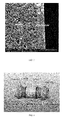
- FIG. 3 illustrates the microstructure of an anode-supported tubular SOEC in accordance with certain aspects of the present disclosure.
- FIG. 4 illustrates a single battery cell subassembly in accordance with certain aspects of the present disclosure.
- FIG. 5 illustrates a flow block diagram of test configuration for the battery in accordance with certain aspects of the present disclosure.
- the present disclosure describes methods of making redox materials for solid oxide redox flow batteries.
- FIG. 1 shows the gas-phase equilibrium compositions of reaction (1) using Fe as an example as a function of temperature.
- the initial molar ratio of C to Fe 2 O 3 is kept to 1. It is evident that the degree of reduction of Fe 2 O 3 to Fe increases with temperature. At about 1000° C., almost all Fe 2 O 3 can be reduced to Fe with a smaller fraction of carbon left.
- the gas composition at about 1000° C. contains only CO and CO 2 in a ratio of close to about 73.2:26.8.
- a typical synthesis procedure can be described as follows. Powders of carbon or graphite are intimately mixed with Fe 2 O 3 and ZrO 2 in a ratio as described herein. The molar ratio of C:Fe 2 O 3 :ZrO 2 ranges from about 1:1:0.05 to about 1:0.30:0.015 to ensure a full reduction of Fe 2 O 3 to Fe. The powder mixture is then placed into a tubular furnace. To facilitate the removal of gas products CO and CO 2 , an inert gas N 2 is used to flush continuously at a flow rate of about 100-500 sccm over the sample surface during the reduction process. The synthesis temperature is about 1000° C. to about 1200° C., at which one to ten hours is usually held. Due to the evolution of gaseous phases CO and CO 2 , a unique porous structure that can facilitate the gas diffusion and surface reaction during battery operation can be obtained.
- the ratio between C and Fe 2 O 3 is important to achieve a fully reduced Fe. Excess C may be preferable in light of battery performance since the residue C can continue to reaction with the reaction gas H 2 O or CO 2 of the battery to produce CO and H 2 for the discharge cycle.
- the C/Fe 2 O 3 /ZrO 2 mixture can also be used as the redox material to be directly assembled into the solid oxide redox flow battery (SORFB).
- the aforementioned chemical reduction of Fe 2 O 3 can also take place in the battery by flowing with N 2 during initial heating up process.
- the unreacted carbon can further react with the battery reaction gas such as H 2 O, CO 2 and a mixture of them during the battery operation to produce extra H 2 and CO for the discharge cycle.
- the degree of reduction of Fe 2 O 3 by C can be monitored in-situ by the SORFB using the EMF technique.
- the measured EMF directly related to the partial pressure of oxygen in the gas phase, is then compared with the thermodynamic analysis to confirm the equilibrium phase composition existent in the redox material. Once the measured EMF matches with the thermodynamic calculation showing full reduction of Fe 2 O 3 to Fe, the battery is then ready for electrical cycles.
- redox material described herein can be utilized with solid oxide redox flow batteries such as those described in U.S. patent application Ser. No. 13/632,694, incorporated by reference herein.
- Such batteries include a cell structure having a solid oxide electrochemical cell and a redox couple bed.
- the batteries can operate between fuel cell and electrolysis modes of a solid oxide electrochemical cell along with an “in-battery” H 2 generation and storage unit to realize charge/discharge characteristics.
- the batteries can include a solid oxide electrochemical cell and a redox couple bed (RCB) utilizing the method described herein, both of which can be operated at elevated temperatures.
- the solid oxide electrochemical cell is a conventional solid oxide fuel cell (SOFC).
- the SOFC includes an electrolyte (such as a Y 2 O 3 -doped ZrO 2 , or the like).
- the electrolyte conducts oxygen ions with the electronic conductivity being kept as low as possible to prevent losses from leakage currents.
- the high operating temperatures of SOFCs allow the kinetics of oxygen ion transport to be sufficient for good performance.
- Other suitable electrolyte materials can include yttria stabilized zirconia, scandia stabilized zirconia, strontium and magnesium doped lanthanum gallate and gadolinium and samarium doped cerin or the like.
- the SOFC further includes an anode (such as a Ni—ZrO 2 cermet or the like).
- the anode layer can be porous and possess predominant electronic conductivity. Suitable materials can include a cermet made up of nickel combined with the ceramic material that is used for the electrolyte in that particular cell, typically YSZ (yttria stabilized zirconia), or the like.
- the SOFC includes a cathode (such as a La 0.6 Sr 0.4 Fe 0.8 Co 0.2 O 3 , or the like) and an interconnect (such as a doped-LaCrO 3 , or the like).
- the interconnect can be either a metallic or ceramic layer that sits between each individual cell. Its purpose is to connect each cell in series, so that the electricity each cell generates can be combined.
- the RCB formed in accordance with the present disclosure can hold a porous nanostructure made of a metal (Me) and its metal oxide (MeO x ) derivative.
- the discharging cycle starts with the introduction of steam into the RCB.
- the purpose of the charging cycle is to convert MeO x to Me.
- One readily available method is to operate a solid oxide electrochemical cell under the electrolysis mode (also known as solid oxide electrolysis cell or SOEC) to generate H 2 from H 2 O; the produced H 2 can then be used to reduce MeO x to Me.
- SOEC solid oxide electrolysis cell
- the charging cycle is completed.
- the freshly reduced active Me is then ready for the next discharging cycle.
- reaction (7) indicates the battery as a “metal-air” battery.
- metal-air batteries such as Li-air and Zn-air
- electrolyte utilized.
- the described battery uses a solid O 2 ⁇ -electrolyte whereas other “metal-air” batteries use a liquid H + -electrolyte. More electrons involved in the charge-transfer process permit the SORFB to achieve higher storage-capacity at a higher rate.
- the redox reactor containing carbon-incorporated redox material is assembled according to FIG. 2 in the form of pellets or slabs.
- the amount of Fe loading determines the capacity of the battery.
- FIG. 3 A cross-sectional view of the anode/electrolyte microstructure after reduction is shown in FIG. 3 , which indicates an approximately 25 ⁇ m-thick YSZ electrolyte on the anode with a reasonably good porosity and pore size.
- the composite cathode ink made up of GDC (Ce 0.8 Gd 0.2 O 2 ) and LSCF (La 0.6 Sr 0.4 Co 0.2 Fe 0.8 O 3- ⁇ ) (LSCFGDC-1, Fuel Cell Materials) was applied to the outer surface of the cell and calcined at 1050° C. for 1 h in open air.
- the currents were collected by silver wires attached on the outer surface of the cathode and one end of the anode as shown in FIG. 4 .
- a layer of silver prepared from silver paste (C8829, Heraeus) was coated prior to attaching the silver wires.
- two Al2O3 rings were attached to the two ends of the cell.
- FIG. 5 shows a schematic view of the assembled battery cell.
- the assembled battery was tested in a test rig shown in FIG. 5 .
- the battery cell By turning off and on certain toggle valves, a closed-loop circulation can be created by the pump.
- the flow rates of all the gases used (N 2 , H 2 and Air) were controlled by the mass flow controllers (MFCs).
- MFCs mass flow controllers
- the desirable H 2 O contents were obtained by passing the carrier gas N 2 or H 2 through a bubbler heated to a fixed temperature.
- An on-line humidity sensor (Vaisala model 332) was deployed to measure the real-time steam content in the gas phase. To prevent condensation, all pipelines were heat-wrapped and kept at 150° C.
- a Solartron 1260/1287 Electrochemical System (not shown in FIG. 5 ) was employed to measure the electrical performance of the battery with software modules such as OCV (open circuit voltage)-t, impedance spectroscopy, potential-dynamic and galvanic square wave.
- a typical characterization procedure can be described as follows. Pure N 2 is first used to purge the entire pipe system several times to remove any possible residual air in the circulation loop. The battery is then heated up to the target temperature of 600-800° C. with a ramp rate of 3° C./min and 200-sccm air and 90-sccm dry H 2 flowing outside and inside of the battery cell, respectively. During this period, the open-circuit voltage is constantly monitored while NiO in the anode of the SOEC is being reduced. After reaching 800° C., dry H 2 is switched to N 2 , the carrier of H 2 O, in the redox cycle unit where oxidation of Fe takes place, producing H 2 for the discharge cycle.
- H 2 O concentration At each H 2 O concentration, OCV-t, impedance spectroscopy, V-I characteristic and galvanic square wave are conducted in a closed-loop flow fashion before H 2 is introduced to reduce the oxidized Fe back to Fe for the next-round characterization.
- H 2 O-bore N 2 To ensure no H 2 is left in the pipeline, H 2 O-bore N 2 is allowed to purge through for 1 minute (obviously some produced H 2 could be lost during the purge) before the measurement starts.
- the outlet and inlet toggle valves Upon closed-loop circulation, the outlet and inlet toggle valves are sequentially shutoff, immediately followed by turning on the pump. The pump was set to a pre-calibrated flow rate of 90 sccm N 2 -flow.
- any ranges of values set forth in this specification are to be construed as written description support for claims reciting any sub-ranges having endpoints which are whole number values within the specified range in question.
- a disclosure in this specification of a range of 1-5 shall be considered to support claims to any of the following sub-ranges: 1-4; 1-3; 1-2; 2-5; 2-4; 2-3; 3-5; 3-4; and 4-5.
Abstract
Description
C+(a+2b)/xMeOx=Me+aCO+bCO2 (1)
xH2O+Me=xH2+MeOx (2)
The formed H2 continues flowing towards the solid oxide electrochemical cell operating under the SOFC mode where it is electrochemically oxidized to generate electricity and steam via the following electrode reaction
xH2 +xO2− =xH2O+2xe − (3)
xH2O+2xe − =xH2 +xO2− (4)
The generated H2 continues flowing towards the RCB where MeOx is reduced into Me by chemical reaction
xH2+MeOx =xH2O+Me (5)
When all the MeOx is reduced to Me by the SOEC-H2, the charging cycle is completed. The freshly reduced active Me is then ready for the next discharging cycle.
Claims (19)
C+(a+2b)/xMeOx→Me+aCO+bCO2
C+(a+2b)/xMeOx→Me+aCO+bCO2
Priority Applications (1)
| Application Number | Priority Date | Filing Date | Title |
|---|---|---|---|
| US13/649,827 US9130219B1 (en) | 2011-10-11 | 2012-10-11 | Method of making redox materials for solid oxide redox flow battery |
Applications Claiming Priority (2)
| Application Number | Priority Date | Filing Date | Title |
|---|---|---|---|
| US201161627362P | 2011-10-11 | 2011-10-11 | |
| US13/649,827 US9130219B1 (en) | 2011-10-11 | 2012-10-11 | Method of making redox materials for solid oxide redox flow battery |
Publications (1)
| Publication Number | Publication Date |
|---|---|
| US9130219B1 true US9130219B1 (en) | 2015-09-08 |
Family
ID=54012663
Family Applications (1)
| Application Number | Title | Priority Date | Filing Date |
|---|---|---|---|
| US13/649,827 Expired - Fee Related US9130219B1 (en) | 2011-10-11 | 2012-10-11 | Method of making redox materials for solid oxide redox flow battery |
Country Status (1)
| Country | Link |
|---|---|
| US (1) | US9130219B1 (en) |
Cited By (7)
| Publication number | Priority date | Publication date | Assignee | Title |
|---|---|---|---|---|
| WO2017097228A1 (en) * | 2015-12-08 | 2017-06-15 | The Chinese University Of Hong Kong | High-energy density and low-cost flow electrochemical devices |
| WO2020056275A1 (en) * | 2018-09-14 | 2020-03-19 | University Of South Carolina | Polybenzimidazole (pbi) membranes for redox flow batteries |
| WO2020056268A3 (en) * | 2018-09-14 | 2020-06-04 | University Of South Carolina | Low permeability polybenzimidazole (pbi) membranes for redox flow batteries |
| US11239491B2 (en) | 2016-11-11 | 2022-02-01 | University Of South Carolina | Solid state electrolyte and electrochemical cell including the electrolyte |
| US11579101B2 (en) * | 2018-06-06 | 2023-02-14 | Panasonic Intellectual Property Management Co., Ltd. | Method for simulating phenomenon involving phase change |
| US11777124B2 (en) | 2020-03-06 | 2023-10-03 | University Of South Carolina | Proton-conducting PBI membrane processing with enhanced performance and durability |
| US11884787B2 (en) | 2018-09-14 | 2024-01-30 | University Of South Carolina | PBI films formed without use of organic solvents |
Citations (17)
| Publication number | Priority date | Publication date | Assignee | Title |
|---|---|---|---|---|
| US5492777A (en) | 1995-01-25 | 1996-02-20 | Westinghouse Electric Corporation | Electrochemical energy conversion and storage system |
| US5656390A (en) * | 1995-02-16 | 1997-08-12 | Kashima-Kita Electric Power Corporation | Redox battery |
| US6103393A (en) * | 1998-02-24 | 2000-08-15 | Superior Micropowders Llc | Metal-carbon composite powders, methods for producing powders and devices fabricated from same |
| US20080113257A1 (en) * | 1998-02-24 | 2008-05-15 | Cabot Corporation | Membrane electrode assemblies for use in fuel cells |
| US7741559B2 (en) * | 2003-05-13 | 2010-06-22 | Asahi Kasei Kabushiki Kaisha | Photoelectric conversion element |
| US20120034520A1 (en) * | 2010-08-09 | 2012-02-09 | Chun Lu | Self-sealed metal electrode for rechargeable oxide-ion battery cells |
| US20120058396A1 (en) * | 2010-09-07 | 2012-03-08 | Chun Lu | Oxidation-resistant metal supported rechargeable oxide-ion battery cells and methods to produce the same |
| US20120077095A1 (en) * | 2010-09-09 | 2012-03-29 | Roumi Farshid | Electrochemical Energy Storage Systems and Methods |
| US20120135278A1 (en) * | 2009-06-09 | 2012-05-31 | Tomohisa Yoshie | Redox flow battery |
| US8343572B2 (en) * | 2007-08-13 | 2013-01-01 | Ashish Varade | Composition of electrode material in the form of a coating and a process thereof |
| US20130189592A1 (en) * | 2010-09-09 | 2013-07-25 | Farshid ROUMI | Part solid, part fluid and flow electrochemical cells including metal-air and li-air battery systems |
| US8541138B2 (en) * | 2005-06-20 | 2013-09-24 | Newsouth Innovations Pty Limited | Perfluorinated membranes and improved electrolytes for redox cells and batteries |
| US8709972B2 (en) * | 2007-02-14 | 2014-04-29 | Nanocarbons Llc | Methods of forming activated carbons |
| US8722227B2 (en) * | 2008-06-12 | 2014-05-13 | Massachusetts Institute Of Technology | High energy density redox flow device |
| US20140322628A1 (en) * | 2011-08-29 | 2014-10-30 | Hiroaki Umeda | Polymer electrolyte membrane, membrane electrode assembly using same and polymer electrolyte fuel cell |
| US20140335440A1 (en) * | 2011-09-21 | 2014-11-13 | Toray Industries, Inc. | Molded article of polymer electrolyte composition and solid polymer type fuel cell using same |
| US20140363747A1 (en) * | 2013-06-07 | 2014-12-11 | Energy Storage Systems, Inc. | Method and system for rebalancing electrolytes in a redox flow battery system |
-
2012
- 2012-10-11 US US13/649,827 patent/US9130219B1/en not_active Expired - Fee Related
Patent Citations (18)
| Publication number | Priority date | Publication date | Assignee | Title |
|---|---|---|---|---|
| US5492777A (en) | 1995-01-25 | 1996-02-20 | Westinghouse Electric Corporation | Electrochemical energy conversion and storage system |
| US5656390A (en) * | 1995-02-16 | 1997-08-12 | Kashima-Kita Electric Power Corporation | Redox battery |
| US6103393A (en) * | 1998-02-24 | 2000-08-15 | Superior Micropowders Llc | Metal-carbon composite powders, methods for producing powders and devices fabricated from same |
| US20080113257A1 (en) * | 1998-02-24 | 2008-05-15 | Cabot Corporation | Membrane electrode assemblies for use in fuel cells |
| US7741559B2 (en) * | 2003-05-13 | 2010-06-22 | Asahi Kasei Kabushiki Kaisha | Photoelectric conversion element |
| US8541138B2 (en) * | 2005-06-20 | 2013-09-24 | Newsouth Innovations Pty Limited | Perfluorinated membranes and improved electrolytes for redox cells and batteries |
| US8709972B2 (en) * | 2007-02-14 | 2014-04-29 | Nanocarbons Llc | Methods of forming activated carbons |
| US8343572B2 (en) * | 2007-08-13 | 2013-01-01 | Ashish Varade | Composition of electrode material in the form of a coating and a process thereof |
| US8722227B2 (en) * | 2008-06-12 | 2014-05-13 | Massachusetts Institute Of Technology | High energy density redox flow device |
| US20120135278A1 (en) * | 2009-06-09 | 2012-05-31 | Tomohisa Yoshie | Redox flow battery |
| US8338025B2 (en) * | 2010-08-09 | 2012-12-25 | Siemens Aktiengesellschaft | Self-sealed metal electrode for rechargeable oxide-ion battery cells |
| US20120034520A1 (en) * | 2010-08-09 | 2012-02-09 | Chun Lu | Self-sealed metal electrode for rechargeable oxide-ion battery cells |
| US20120058396A1 (en) * | 2010-09-07 | 2012-03-08 | Chun Lu | Oxidation-resistant metal supported rechargeable oxide-ion battery cells and methods to produce the same |
| US20120077095A1 (en) * | 2010-09-09 | 2012-03-29 | Roumi Farshid | Electrochemical Energy Storage Systems and Methods |
| US20130189592A1 (en) * | 2010-09-09 | 2013-07-25 | Farshid ROUMI | Part solid, part fluid and flow electrochemical cells including metal-air and li-air battery systems |
| US20140322628A1 (en) * | 2011-08-29 | 2014-10-30 | Hiroaki Umeda | Polymer electrolyte membrane, membrane electrode assembly using same and polymer electrolyte fuel cell |
| US20140335440A1 (en) * | 2011-09-21 | 2014-11-13 | Toray Industries, Inc. | Molded article of polymer electrolyte composition and solid polymer type fuel cell using same |
| US20140363747A1 (en) * | 2013-06-07 | 2014-12-11 | Energy Storage Systems, Inc. | Method and system for rebalancing electrolytes in a redox flow battery system |
Non-Patent Citations (3)
| Title |
|---|
| Alotto et al.; 'Redox Flow Batteries for large scale energy storage'; Publication Year: 2012; Energy Conference and Exhibition (ENERGYCON), 2012 IEEE International; pp. 293-298. * |
| Tsuda et al., "Development of intermittent redox flow battery for PV system"; Publication Year: 1994; Photovoltaic Energy Conversion, 1994., Conference Record of the Twenty Fourth. IEEE Photovoltaic Specialists Conference-1994, 1994 IEEE First World Conference on; vol. 1; pp. 946-949 vol. 1. * |
| U.S. Appl. No. 13/632,694, filed Oct. 1, 2012, Huang et al., "Solid Oxide Redox Flow Battery". |
Cited By (11)
| Publication number | Priority date | Publication date | Assignee | Title |
|---|---|---|---|---|
| WO2017097228A1 (en) * | 2015-12-08 | 2017-06-15 | The Chinese University Of Hong Kong | High-energy density and low-cost flow electrochemical devices |
| US11239491B2 (en) | 2016-11-11 | 2022-02-01 | University Of South Carolina | Solid state electrolyte and electrochemical cell including the electrolyte |
| US11579101B2 (en) * | 2018-06-06 | 2023-02-14 | Panasonic Intellectual Property Management Co., Ltd. | Method for simulating phenomenon involving phase change |
| WO2020056275A1 (en) * | 2018-09-14 | 2020-03-19 | University Of South Carolina | Polybenzimidazole (pbi) membranes for redox flow batteries |
| WO2020056268A3 (en) * | 2018-09-14 | 2020-06-04 | University Of South Carolina | Low permeability polybenzimidazole (pbi) membranes for redox flow batteries |
| CN112956056A (en) * | 2018-09-14 | 2021-06-11 | 南卡罗来纳大学 | Low permeability Polybenzimidazole (PBI) membranes for redox flow batteries |
| US11302948B2 (en) | 2018-09-14 | 2022-04-12 | University Of South Carolina | Polybenzimidazole (PBI) membranes for redox flow batteries |
| US11482721B2 (en) | 2018-09-14 | 2022-10-25 | University Of South Carolina | Low permeability polybenzimidazole (PBI) gel membranes for redox flow batteries |
| US11799112B2 (en) | 2018-09-14 | 2023-10-24 | University Of South Carolina | Polybenzimidazole (PBI) membranes for redox flow batteries |
| US11884787B2 (en) | 2018-09-14 | 2024-01-30 | University Of South Carolina | PBI films formed without use of organic solvents |
| US11777124B2 (en) | 2020-03-06 | 2023-10-03 | University Of South Carolina | Proton-conducting PBI membrane processing with enhanced performance and durability |
Similar Documents
| Publication | Publication Date | Title |
|---|---|---|
| US9130219B1 (en) | Method of making redox materials for solid oxide redox flow battery | |
| Park et al. | Direct oxidation of hydrocarbons in a solid oxide fuel cell: I. Methane oxidation | |
| Xing et al. | Co-electrolysis of steam and CO2 in a solid oxide electrolysis cell with La0. 75Sr0. 25Cr0. 5Mn0. 5O3− δ–Cu ceramic composite electrode | |
| Marina et al. | A solid oxide fuel cell with a gadolinia-doped ceria anode: preparation and performance | |
| Sumi et al. | Performance of nickel–scandia-stabilized zirconia cermet anodes for SOFCs in 3% H2O–CH4 | |
| DK1532710T3 (en) | PEROVSKIT-BASED FUEL CELL ELECTRODE AND MEMBRANE | |
| Asano et al. | A novel solid oxide fuel cell system using the partial oxidation of methane | |
| Li et al. | Achieving high-efficiency hydrogen production using planar solid-oxide electrolysis stacks | |
| Buccheri et al. | Anode-versus electrolyte-supported Ni-YSZ/YSZ/Pt SOFCs: Effect of cell design on OCV, performance and carbon formation for the direct utilization of dry methane | |
| Yu et al. | All-solid-state direct carbon fuel cells with thin yttrium-stabilized-zirconia electrolyte supported on nickel and iron bimetal-based anodes | |
| US20070009784A1 (en) | Materials system for intermediate-temperature SOFC based on doped lanthanum-gallate electrolyte | |
| Zhang et al. | Behavior of strontium-and magnesium-doped gallate electrolyte in direct carbon solid oxide fuel cells | |
| Bozza et al. | High performance anode-supported intermediate temperature solid oxide fuel cells (IT-SOFCs) with La0. 8Sr0. 2Ga0. 8Mg0. 2O3− δ electrolyte films prepared by electrophoretic deposition | |
| JP5226290B2 (en) | Solid oxide battery | |
| Yu et al. | Interfacial reactions in ceramic membrane reactors for syngas production | |
| Xing et al. | Preparation and characterization of La0. 75Sr0. 25Cr0. 5Mn0. 5O3− δ-yttria stabilized zirconia cathode supported solid oxide electrolysis cells for hydrogen generation | |
| Lin et al. | A novel Ba0. 6Sr0. 4Co0. 9Nb0. 1O3− δ cathode for protonic solid-oxide fuel cells | |
| US9236627B1 (en) | Solid oxide redox flow battery | |
| JP5284596B2 (en) | Solid oxide battery | |
| Peng et al. | Pr1. 8La0. 2Ni0. 74Cu0. 21Ga0. 05O4+ δ as a potential cathode material with CO2 resistance for intermediate temperature solid oxide fuel cell | |
| Zhou et al. | Cathode water management towards improved performance of protonic ceramic fuel cells | |
| Yan et al. | An all-solid-state carbon-air battery reaching an output power over 10 W and a specific energy of 3600 Wh kg− 1 | |
| Ye et al. | Use of La0. 75Sr0. 25Cr0. 5Mn0. 5O3 materials in composite anodes for direct ethanol solid oxide fuel cells | |
| Zhang et al. | BaFe0. 6Co0. 3Ce0. 1O3− δ as cathode materials for proton-conducting solid oxide fuel cells | |
| JP5858249B2 (en) | Solid oxide fuel cell and method for producing solid oxide fuel cell |
Legal Events
| Date | Code | Title | Description |
|---|---|---|---|
| AS | Assignment |
Owner name: UNIVERSITY OF SOUTH CAROLINA, SOUTH CAROLINA Free format text: ASSIGNMENT OF ASSIGNORS INTEREST;ASSIGNORS:HUANG, KEVIN;LI, XUE;REEL/FRAME:029373/0750 Effective date: 20121022 |
|
| ZAAA | Notice of allowance and fees due |
Free format text: ORIGINAL CODE: NOA |
|
| ZAAB | Notice of allowance mailed |
Free format text: ORIGINAL CODE: MN/=. |
|
| STCF | Information on status: patent grant |
Free format text: PATENTED CASE |
|
| CC | Certificate of correction | ||
| MAFP | Maintenance fee payment |
Free format text: PAYMENT OF MAINTENANCE FEE, 4TH YR, SMALL ENTITY (ORIGINAL EVENT CODE: M2551); ENTITY STATUS OF PATENT OWNER: SMALL ENTITY Year of fee payment: 4 |
|
| FEPP | Fee payment procedure |
Free format text: MAINTENANCE FEE REMINDER MAILED (ORIGINAL EVENT CODE: REM.); ENTITY STATUS OF PATENT OWNER: SMALL ENTITY |
|
| LAPS | Lapse for failure to pay maintenance fees |
Free format text: PATENT EXPIRED FOR FAILURE TO PAY MAINTENANCE FEES (ORIGINAL EVENT CODE: EXP.); ENTITY STATUS OF PATENT OWNER: SMALL ENTITY |
|
| STCH | Information on status: patent discontinuation |
Free format text: PATENT EXPIRED DUE TO NONPAYMENT OF MAINTENANCE FEES UNDER 37 CFR 1.362 |
|
| FP | Lapsed due to failure to pay maintenance fee |
Effective date: 20230908 |