US9129741B2 - Method and apparatus for wireless power transmission - Google Patents
Method and apparatus for wireless power transmission Download PDFInfo
- Publication number
- US9129741B2 US9129741B2 US11/901,158 US90115807A US9129741B2 US 9129741 B2 US9129741 B2 US 9129741B2 US 90115807 A US90115807 A US 90115807A US 9129741 B2 US9129741 B2 US 9129741B2
- Authority
- US
- United States
- Prior art keywords
- planar spiral
- spiral inductor
- array
- inductors
- inductor
- Prior art date
- Legal status (The legal status is an assumption and is not a legal conclusion. Google has not performed a legal analysis and makes no representation as to the accuracy of the status listed.)
- Active, expires
Links
- 238000000034 method Methods 0.000 title claims abstract description 14
- 230000005540 biological transmission Effects 0.000 title description 4
- 230000005291 magnetic effect Effects 0.000 claims abstract description 55
- 238000012546 transfer Methods 0.000 claims abstract description 17
- 238000009826 distribution Methods 0.000 claims description 26
- 230000000694 effects Effects 0.000 claims description 17
- 230000001965 increasing effect Effects 0.000 claims description 12
- 230000003044 adaptive effect Effects 0.000 claims description 9
- 230000007246 mechanism Effects 0.000 claims description 5
- 230000008878 coupling Effects 0.000 abstract description 18
- 238000010168 coupling process Methods 0.000 abstract description 18
- 238000005859 coupling reaction Methods 0.000 abstract description 18
- 238000005516 engineering process Methods 0.000 abstract description 9
- 238000004519 manufacturing process Methods 0.000 abstract description 5
- 229920001690 polydopamine Polymers 0.000 abstract description 5
- 239000010410 layer Substances 0.000 description 16
- 239000004020 conductor Substances 0.000 description 15
- 230000001939 inductive effect Effects 0.000 description 13
- 238000013461 design Methods 0.000 description 12
- 238000004804 winding Methods 0.000 description 12
- 239000011162 core material Substances 0.000 description 10
- 239000002356 single layer Substances 0.000 description 8
- 239000002184 metal Substances 0.000 description 6
- 229910052751 metal Inorganic materials 0.000 description 6
- 239000013598 vector Substances 0.000 description 6
- 239000003990 capacitor Substances 0.000 description 5
- 230000001066 destructive effect Effects 0.000 description 4
- 230000005294 ferromagnetic effect Effects 0.000 description 4
- 238000003780 insertion Methods 0.000 description 3
- 230000037431 insertion Effects 0.000 description 3
- 238000003491 array Methods 0.000 description 2
- 238000010586 diagram Methods 0.000 description 2
- 230000010354 integration Effects 0.000 description 2
- 230000003287 optical effect Effects 0.000 description 2
- 238000005457 optimization Methods 0.000 description 2
- 239000004065 semiconductor Substances 0.000 description 2
- 238000004088 simulation Methods 0.000 description 2
- 239000000758 substrate Substances 0.000 description 2
- 238000012360 testing method Methods 0.000 description 2
- 241000721662 Juniperus Species 0.000 description 1
- 238000013459 approach Methods 0.000 description 1
- 230000008901 benefit Effects 0.000 description 1
- XMQFTWRPUQYINF-UHFFFAOYSA-N bensulfuron-methyl Chemical compound COC(=O)C1=CC=CC=C1CS(=O)(=O)NC(=O)NC1=NC(OC)=CC(OC)=N1 XMQFTWRPUQYINF-UHFFFAOYSA-N 0.000 description 1
- 239000006227 byproduct Substances 0.000 description 1
- 238000006243 chemical reaction Methods 0.000 description 1
- 238000005094 computer simulation Methods 0.000 description 1
- 239000012141 concentrate Substances 0.000 description 1
- 238000001816 cooling Methods 0.000 description 1
- 239000003302 ferromagnetic material Substances 0.000 description 1
- 230000004907 flux Effects 0.000 description 1
- 238000009499 grossing Methods 0.000 description 1
- 238000002847 impedance measurement Methods 0.000 description 1
- 230000003993 interaction Effects 0.000 description 1
- 238000005259 measurement Methods 0.000 description 1
- 238000012986 modification Methods 0.000 description 1
- 230000004048 modification Effects 0.000 description 1
- 230000003071 parasitic effect Effects 0.000 description 1
- 150000003071 polychlorinated biphenyls Chemical class 0.000 description 1
- 238000005086 pumping Methods 0.000 description 1
- 230000009467 reduction Effects 0.000 description 1
- 238000011160 research Methods 0.000 description 1
- 230000004044 response Effects 0.000 description 1
- 239000000523 sample Substances 0.000 description 1
- 238000000926 separation method Methods 0.000 description 1
- 238000004513 sizing Methods 0.000 description 1
- 239000002699 waste material Substances 0.000 description 1
Images


Classifications
-
- H—ELECTRICITY
- H02—GENERATION; CONVERSION OR DISTRIBUTION OF ELECTRIC POWER
- H02J—CIRCUIT ARRANGEMENTS OR SYSTEMS FOR SUPPLYING OR DISTRIBUTING ELECTRIC POWER; SYSTEMS FOR STORING ELECTRIC ENERGY
- H02J50/00—Circuit arrangements or systems for wireless supply or distribution of electric power
- H02J50/40—Circuit arrangements or systems for wireless supply or distribution of electric power using two or more transmitting or receiving devices
- H02J50/402—Circuit arrangements or systems for wireless supply or distribution of electric power using two or more transmitting or receiving devices the two or more transmitting or the two or more receiving devices being integrated in the same unit, e.g. power mats with several coils or antennas with several sub-antennas
-
- A—HUMAN NECESSITIES
- A61—MEDICAL OR VETERINARY SCIENCE; HYGIENE
- A61C—DENTISTRY; APPARATUS OR METHODS FOR ORAL OR DENTAL HYGIENE
- A61C17/00—Devices for cleaning, polishing, rinsing or drying teeth, teeth cavities or prostheses; Saliva removers; Dental appliances for receiving spittle
- A61C17/16—Power-driven cleaning or polishing devices
- A61C17/22—Power-driven cleaning or polishing devices with brushes, cushions, cups, or the like
- A61C17/224—Electrical recharging arrangements
-
- H—ELECTRICITY
- H01—ELECTRIC ELEMENTS
- H01F—MAGNETS; INDUCTANCES; TRANSFORMERS; SELECTION OF MATERIALS FOR THEIR MAGNETIC PROPERTIES
- H01F38/00—Adaptations of transformers or inductances for specific applications or functions
- H01F38/14—Inductive couplings
-
- H—ELECTRICITY
- H02—GENERATION; CONVERSION OR DISTRIBUTION OF ELECTRIC POWER
- H02J—CIRCUIT ARRANGEMENTS OR SYSTEMS FOR SUPPLYING OR DISTRIBUTING ELECTRIC POWER; SYSTEMS FOR STORING ELECTRIC ENERGY
- H02J50/00—Circuit arrangements or systems for wireless supply or distribution of electric power
- H02J50/10—Circuit arrangements or systems for wireless supply or distribution of electric power using inductive coupling
- H02J50/12—Circuit arrangements or systems for wireless supply or distribution of electric power using inductive coupling of the resonant type
-
- H02J7/025—
-
- H—ELECTRICITY
- H01—ELECTRIC ELEMENTS
- H01F—MAGNETS; INDUCTANCES; TRANSFORMERS; SELECTION OF MATERIALS FOR THEIR MAGNETIC PROPERTIES
- H01F17/00—Fixed inductances of the signal type
- H01F17/0006—Printed inductances
-
- H—ELECTRICITY
- H02—GENERATION; CONVERSION OR DISTRIBUTION OF ELECTRIC POWER
- H02J—CIRCUIT ARRANGEMENTS OR SYSTEMS FOR SUPPLYING OR DISTRIBUTING ELECTRIC POWER; SYSTEMS FOR STORING ELECTRIC ENERGY
- H02J50/00—Circuit arrangements or systems for wireless supply or distribution of electric power
- H02J50/10—Circuit arrangements or systems for wireless supply or distribution of electric power using inductive coupling
-
- H—ELECTRICITY
- H02—GENERATION; CONVERSION OR DISTRIBUTION OF ELECTRIC POWER
- H02J—CIRCUIT ARRANGEMENTS OR SYSTEMS FOR SUPPLYING OR DISTRIBUTING ELECTRIC POWER; SYSTEMS FOR STORING ELECTRIC ENERGY
- H02J50/00—Circuit arrangements or systems for wireless supply or distribution of electric power
- H02J50/90—Circuit arrangements or systems for wireless supply or distribution of electric power involving detection or optimisation of position, e.g. alignment
-
- H—ELECTRICITY
- H02—GENERATION; CONVERSION OR DISTRIBUTION OF ELECTRIC POWER
- H02J—CIRCUIT ARRANGEMENTS OR SYSTEMS FOR SUPPLYING OR DISTRIBUTING ELECTRIC POWER; SYSTEMS FOR STORING ELECTRIC ENERGY
- H02J7/00—Circuit arrangements for charging or depolarising batteries or for supplying loads from batteries
- H02J7/0042—Circuit arrangements for charging or depolarising batteries or for supplying loads from batteries characterised by the mechanical construction
Definitions
- FIG. 3 SplashPower, founded by two Cambridge University students in June 2001, has disclosed a system that uses two perpendicular coils to create an even magnetic field distribution over a planar surface, as shown in FIG. 3 .
- the coils alternate switching on and off to create two perpendicular magnetic fields, parallel to the base stations surface.
- FIG. 4 When a device with a secondary winding having a highly permeable core is placed on the base station, magnetic fields will tend to travel through the low reluctance core rather than the surrounding air as shown in FIG. 4 .
- FIG. 4 FIG.
- FIG 4 shows cross sectional views of SplashPower base station illustrating magnetic field lines ( 1 ), where the top figure shows undisturbed (no device present) field lines during normal operation and the middle figure shows the effect of placing a piece of ferromagnetic material ( 800 ) in the magnetic fields.
- the field lines can be seen traveling through the core rather than the surrounding air.
- the bottom figure simulates two individual cores in the magnetic field. Again, the magnetic fields travel through the core material rather than surrounding air.
- SplashPower indicates that specially equipped electronic devices can receive charge in any position or orientation on top of the base station.
- the SplashPower design has receivers built to include a dense ferromagnetic core, which would add undesirable bulk to small devices.
- SplashPower base station uses a two coil layout, it may waste large amounts of power, especially if a user attempts to charge a device in the corner of the pad.
- SplashPower's base station can be thick and clunky due to the inclusion of a dense ferromagnetic core.
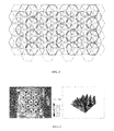
- FIG. 5 shows a three layer array of hexagonal inductive coils, as shown in FIG. 5 .
- FIG. 6 shows an mmf scan of a single layer
- FIG. 7 shows an mmf scan of the three layers.
- the inductive coils are coreless to allow a small, lightweight, low cost system.
- a receiving coil placed on top of the transmitter as shown in FIG. 5 can be used to charge an electronic device.
- interactions between multiple layers may hinder system performance, and the fabrication of multilayer PCB boards is considerably more expensive than single layer boards.
- Embodiments of the invention relate to a method and system for transferring power wirelessly to electronic devices.
- the system can utilize magnetic coupling between two coils at close proximity to transfer sufficient power to charge an electronic device.
- Embodiments of the invention pertain to an array of spiral coils that can be used to transmit power for transfer to receiver coils. Potential applications of this technology include charging consumer electronic devices (cell phones, laptops, PDAs, etc), developing hermetically sealed devices for extreme environments, and less invasive transcutaneous energy transfer (TET) systems.
- TET transcutaneous energy transfer
- Various embodiments of the subject system can be referred to as PowerPad system.
- Embodiments can incorporate one or more of the following: planar inductors, PCB transformers, and very high frequency power supplies.
- Embodiments of the invention also pertain to planar inductors, and/or arrays of planar inductors, having characteristics that allow the production of an even magnetic field, as well as systems that incorporate such planar inductors.
- An embodiment of the PowerPad system can include two primary components: a base station, which can be referred to as PowerPad, and one or more receivers, which can be referred to as Power Mate.
- An embodiment of the base station is a planar device that provides power to the receiver modules.
- the PowerPad can simultaneously power multiple devices of different make, model, and power configuration placed in any position or orientation on its surface.
- the PowerPad can utilize an array of inductive coils attached to one or more high frequency power supplies.
- the PowerPad can be, for example, scaled to cover an entire desktop or integrated into an airplane tray table.
- Embodiments of the PowerPad can provide sufficient power to operate laptops, flat panel monitors, PDAs, cell phones, mp3 players, and other consumer electronic devices.
- the receiver which can be referred to as PowerMate, can be integrated into the chassis of an electronic device and can receive charge from the PowerPad.
- PowerMate is a relatively simple, low-cost receiving device designed to work in conjunction with the PowerPad.
- Devices equipped with a PowerMate unit receive power by being placed anywhere, directly on top of a PowerPad base station.
- the PowerMate can be small and lightweight.
- the device is scalable to satisfy the requirements of larger more power hungry devices.
- a unit 1 mm thick and 36 mm in diameter is utilized and can receive more than enough power to drive a laptop computer or flat panel monitor.
- FIG. 1 shows an embodiment of Power Pad System.
- FIGS. 2A-2C show wireless technology used in electric toothbrushes and razors, where ferromagnetic cores are at the center of each winding and magnetic fields created by the bottom winding (base) induce current in the top winding (device).
- FIG. 3 shows a top down view of the two coils in the SplashPower base station where magnetic fields directions are shown as large arrows.
- FIG. 4 shows magnetic field patterns for a SplashPower base station.
- FIG. 5 shows a structure of three-layer hexagonal array.
- FIG. 6 shows an mmf scan for a single layer design having an uneven magnetic field.
- FIG. 7 shows an mmf scan for three layer design, where the distribution of magnetic fields improves considerably, compared to the distribution of FIG. 6 .
- FIG. 8 shows an embodiment of a PowerMate module driving an LED on top of an embodiment of a Power Pad surface.
- FIG. 9 shows a PowerPad system block diagram for a specific embodiment in accordance with the subject invention.
- FIG. 10 shows a driving circuit used in an embodiment of a PowerPad.
- FIG. 11 shows a Magnetic field (H Field) vector and magnitude plot for a spiral inductor cross-section having an uneven field distribution with peak fields in the center and minimum fields on the perimeter.
- FIG. 12 shows a Protei layout of a top layer, where the location of the bottom layer is drawn in light circles.
- FIG. 13 shows a schematic for an embodiment of a PowerMate.
- FIG. 14 shows the received power vs. driving circuit frequency for an embodiment of the subject invention.
- FIG. 15 shows a relative voltage distribution over the surface of an embodiment of the PowerPad.
- FIG. 16 shows a microprocessor controlled half bridge inverter that can be utilized in accordance with an embodiment of the subject PowerPad.
- FIG. 17 shows a voltage waveform measured across the PowerPad terminals before and after insertion of the capacitor shown in FIG. 16 .
- FIG. 18 shows impedance vs. frequency for a PCB transformer.
- FIG. 19 shows voltage gain vs. frequency for a PCB transformer.
- FIG. 20 shows Ansoft HFSS H field vectors that can be seen flowing in opposing directions, where the large arrows show a generalization of the net effect.
- FIG. 21 shows a close up of the magnetic field vectors along the perimeter of a spiral inductor.
- FIG. 22 shows a voltage distribution over the surface of a two layer array that shows coil overlap compared to received voltage.
- FIG. 23 shows the magnetic field intensity measured at 0.4 mm over a square inductive coil.
- FIG. 24 shows the effect of trace width and spacing on Q factor.
- FIG. 25 shows the magnetic field distribution of a typical planar inductor, where the field peaks in the center.
- FIG. 26 shows the effect of variable width planar inductor on magnetic field.
- FIG. 27 shows the current crowding effect seen on a planar inductor.
- FIG. 28 shows an example of a subdivided embodiment of a PowerPad.
- FIG. 29 shows an embodiment of a circuit schematic that can be utilized to drive the subdivided PowerPad layout shown in FIG. 2B .
- FIG. 30 shows the H field magnitude of two spiral inductors placed side by side.
- FIG. 31 shows a circuit equivalent of a planar, coreless PCB transformer.
- FIG. 32 shows a block diagram of an embodiment of a PowerPad having six components, in accordance with the subject invention.
- FIG. 33 shows an embodiment of a PowerPad spiral inductor array layout in accordance with the subject invention.
- FIG. 34 shows a received waveform of an embodiment of the PowerMate produced under indicated coil and voltage conditions.
- Embodiments of the invention relate to a method and system for transferring power wirelessly to electronic devices.
- the system can utilize magnetic coupling between two coils at close proximity to transfer sufficient power to charge an electronic device.
- Embodiments of the invention pertain to an array of spiral coils that can be used to transmit power for transfer to receiver coils. Potential applications of this technology include charging consumer electronic devices (cell phones, laptops, PDAs, etc), developing hermetically sealed devices for extreme environments, and less invasive transcutaneous energy transfer (TET) systems.
- TET transcutaneous energy transfer
- Various embodiments of the subject system can be referred to as Power Pad system.
- Embodiments can incorporate one or more of the following: planar inductors, PCB transformers, and very high frequency power supplies.
- Embodiments of the invention also pertain to planar inductors having characteristics that allow the production of even magnetic field, as well as systems that incorporate such planar inductors.
- FIG. 1 shows an embodiment of a PowerPad system in accordance with the subject invention.
- An embodiment of the PowerPad system can include two primary components: a Base Station, which can be referred to as PowerPad, and one or more receivers, which can be referred to as PowerMate.
- An embodiment of the base station is a planar device that provides power to the receiver modules.
- the PowerPad can simultaneously power multiple devices of different make, model, and power configuration placed in any position or orientation on its surface.
- the PowerPad can utilize an array of inductive coils attached to one or more high frequency power supplies.
- the PowerPad can be, for example, scaled to cover an entire desktop or integrated into an airplane tray table.
- Embodiments of the Power Pad can provide sufficient power to operate laptops, flat panel monitors, PDAs, cell phones, mp3 players, and other consumer electronic devices.
- M. Peter, H. Hein, F. Oehler, P. Baureis, “Planar Inductors with Subdivided Conductors for Reducing Eddy Current Effects,” IEEE, 2003 provides an overview of existing technologies, discusses operational theory applicable to embodiments of the Power Pad system, and is hereby incorporated by reference in its entirety.
- the receiver which can be referred to as PowerMate, can be integrated into the chassis of an electronic device and can receive charge from the PowerPad.
- the PowerMate is a relatively simple, low-cost receiving device designed to work in conjunction with the PowerPad.
- Devices equipped with a PowerMate unit receive power by being placed anywhere, directly on top of a PowerPad base station.
- the PowerMate can be small and lightweight.
- the device is scalable to satisfy the requirements of larger more power hungry devices. In an embodiment, a unit 1 mm thick and 36 mm in diameter is utilized and can receive more than enough power to drive a laptop computer or flat panel monitor.
- devices can be placed on the pad in any orientation. Without the need to carefully position the device or fumble with adapters.
- the PowerPad can eliminate power cables for all types of electronic devices, and eliminate the associated unsightly wire nests.
- An embodiment of the Power Pad is a versatile device capable of providing power to almost any type of electronic device. Power Pad can charge multiple devices at once as if they were plugged into their conventional adapters. Embodiments of the Power Pad can be integrated into desks, tables, and other flat surfaces. Users can take their devices to the coffee shop, lecture hall, or an airplane and charge their devices on PowerPad enabled surfaces. Electronic device manufacturers can integrate the subject technology into their devices.
- Embodiments of the subject system utilize PCB transformers, which incorporate polychlorinated biphenyls (PCB's). Embodiments of the invention utilize multiple layers of coils for generation of magnetic fields.
- An LED equipped with a PowerMate receiver module, in accordance with an embodiment of the invention, as shown in FIG. 8 reliably illuminated when placed in any position or orientation on top of an embodiment of the PowerPad's surface.
- an embodiment of the PowerPad base station In order to charge devices placed in various locations on its surface, and in a specific embodiment anywhere on its surface, an embodiment of the PowerPad base station generates an even high frequency, magnetic field.
- the PowerMate receiver converts this magnetomotive force into electrical current and supplies power to, for example, an electronic device.
- a specific embodiment of the invention has four primary components and will be described with reference to FIG. 9 .
- a DC power supply 310 uses three 1A, 13.5/30V RadioShack power supplies connected in series to produce a 65V output. During steady-state operation the entire system draws a maximum of 0.65 amps.
- a microprocessor controlled driving circuit 330 includes two cascaded resistive load switches, as shown in FIG. 10 .
- a PIC12F629 8-pin microprocessor switches a 2N3819 n-channel MOSFET at 208 kHz. The drain terminal of the 2N3819 MOSFET drives the gate of a larger IRF640 power MOSFET.
- the output is a 65 Vpp, 208 kHz square wave output that feeds into the PowerPad base station.
- Magnetic field vector and magnitude field plots of spiral inductor cross-sections are shown in FIG. 11 , and reveal peak intensity at the center of the inductor and minimum intensity along the perimeter.
- a second layer of inductors can be arranged, as shown in FIG. 12 , such that the peak magnetic field regions of the bottom layer align with minimum magnetic field regions of the top.
- the embodiment of the PowerPad shown in FIG. 12 uses a two layer, series connected, array of PCB, spiral inductors to create an even magnetic field over its surface. Inductors are arranged in series so that current does not bypass the loaded region of the Power Pad.
- the inductors are 15 turn inductors with 15 mil trace widths and 25 mil trace gaps.
- the receiving device for this embodiment includes a 33 turn, 22 gauge magnet wire coil connected to a full bridge rectifier. Current flows from the rectifier into a parallel connected LED and 220 capacitor, as shown in FIG. 13 .
- Table 4.1 shows the system specifications for a specific embodiment of the invention.
- Increasing the DC supply voltage can yield proportional gains in received power. With respect to frequencies from 0 to 200 kHz, a higher frequency can result in more efficient coupling, as shown in FIG. 14 , which shows received power vs. driving circuit frequency.
- Probe measurements above an embodiment of the Power Pad reveal peak voltages around the perimeter and lower voltages in the center, as shown in FIG. 15 , which shows a relative voltage distribution over the surface of the PowerPad.
- the low voltage region is likely attributable to destructive interference between the top and bottom layer inductor arrays.
- FIG. 34 illustrates a table including test results of the PowerMate with PowerPad input of: 146 kHz; 130 Vp-p, 50% duty cycle, square wave.
- a specific embodiment of the PowerMate, listed last in the table of FIG. 34 uses a 33 turn, 22 gauge magnet wire coil.
- the resistive load configuration of an embodiment of a driving circuit dissipated 18.4 watts of power as heat loss and delivered 55% of the input power to the PowerPad.
- the heat byproduct can be addressed with several large heat sinks and fans to regulate the temperature of the prototype.
- FIG. 16 Another embodiment, having a circuit employing a microprocessor controlled, halfbridge inverter, as shown in FIG. 16 , is designed without resistive elements and significantly reduces the wasted power.
- a microprocessor transmits two high frequency signals, 180 degrees out of phase, to the high and low side inputs of an IR21 01 gate driver.
- the gate driver switches two n-channel MOSFETs that create a high frequency, 65V square wave feeding into the PowerPad base station. This driving circuit delivered ⁇ 95% of the input to the PowerPad and significantly reduced the cooling requirement.
- the half-bridge inverter design permits the insertion of a capacitor between the PowerPad and ground, as shown in FIG. 16 .
- This addition can double the peak to peak voltage by pumping charge back through the PowerPad as it is switched from 65 volts to ground, as shown in FIG. 17 , which shows a voltage waveform measured across the PowerPad terminals before and after insertion of the capacitor shown in FIG. 16 .
- the resonant frequency of typical core less PCB transformers is between 1 and 10 MHz [5]. At much lower frequencies, the primary windings behave like a short circuit and dissipate a large amount of power. Studies have shown that voltage gain is highest and power transfer is most efficient, at the maximum impedance frequency, as illustrated in FIG. 18 and FIG. 19 , where FIG. 18 shows impedance versus frequency for a PCB transformer, and FIG. 19 shows voltage gain versus frequency for a PCB transformer. The maximum impedance frequency is indicated in FIG. 18 . Referring to FIG. 19 , gain increases significantly at the maximum impedance frequency (208 kHz). The frequency of existing driving circuit is shown (208 kHz). At this ideal frequency, which is generally found immediately below the resonant frequency, 90% efficient embodiments of systems in accordance with the invention have been built and tested.
- the PIC microprocessor used in an embodiment has a maximum stable output of 208 kHz, significantly lower than the optimum frequency range from FIG. 19 .
- a microprocessor with a ⁇ 10 MHz switching capability can substantially improve efficiency. Switching losses in today's power electronics can become too large to operate efficiently beyond 10 MHz.
- FIG. 20 Simulations using Ansoft HFSS 3D electromagnetic simulation software provide better insight into the destructive interference patterns, as shown in FIG. 20 , which shown Ansoft HFSS H field vectors that are flowing in opposing directions.
- the large arrows in FIG. 20 show a generalization of the net effect.
- Magnetomotive force peaks at the center of a planar inductor and is negative around the perimeter, as shown in FIG. 21 , which shows a close up of the magnetic field vectors along the perimeter of a spiral inductor. Referring to FIG. 21 , the fields at the perimeter are opposite in direction to the fields at the center. By layering and aligning coils as shown in FIG. 12 opposing magnetic fields are created thereby reducing coupling efficiency.
- Test data shows maximum voltages are located at the corners where coil overlap is minimal, medium voltages are found around the perimeter where overlap is moderate, and the lowest voltages occur in the center where inductor overlap is the greatest, as illustrated in FIG. 22 , which shows a voltage distribution over the surface of a two layer array.
- FIG. 22 indicates that minimum overlap between layers results in maximum efficiency.
- An embodiment with a single layer of array coil may allow maximum efficiency.
- the inductive coils in an embodiment have a thin 15 mil trace width and a 25 mil trace gap. This arrangement was based on the assumption that current carrying traces obstruct magnetic fields and therefore, large trace separations would contribute to good inductive coupling as illustrated in FIG. 23 , which shows the magnetic filed intensity measured at 0.4 mm over a square inductive coil. The magnetic fields have been blocked in the regions found immediately above the conducting traces.
- FIG. 24 shows the Q factor for a thin trace and large trace gap spiral coil, which show a 50% lower quality factor for the thin trace width coil that is centered on a frequency too high for power electronics.
- the thin trace design has a much lower Q factor and resonated at frequencies too high for certain desired driving circuit designs.
- Embodiments of the invention can incorporate inductors where the traces are widened and the gaps are narrowed. The ratio of the trace to gap widths can be optimized for efficiency, or determined to meet other design criteria. In an embodiment, inter-winding capacitance can be neglected due to the relatively low operating frequency and the inductor's short overall conductor length.
- the inductors can have a square or hexagonal coil shape, to allow for a more efficient use of board space. Square and hexagonal inductors can be tiled with little wasted space. Other embodiments can have other shapes, such as a circular pattern.
- FIG. 25 shows the magnetic field distribution of a typical planar inductor.
- the unevenness can be difficult to fully eliminate.
- the unevenness can be reduced by using traces that become thicker as they spiral towards the center. Thick current carrying traces at the center of the inductor can block the peak magnetic field for a more balanced field distribution, as shown in FIG. 26 , which illustrates the effect of the variable width planar inductor on magnetic field.
- the wider conductor 200 in the middle is clearly limiting the magnetic field flux through that region.
- thin perimeter 210 traces can reduce the size of the region of minimum field intensity.
- the corners of a square inductor can begin to obstruct current beginning in the MHz range due to the current crowding effect [ 7 ].
- Magnetic fields tend to push current distribution towards the center of the inductor, reducing the effective cross-sectional area of the conductor and thereby increasing resistance. This effect is seen throughout the conductor, but becomes especially dominate towards the center and at the corners as shown in FIG. 27 , which shows the current crowding effect seen on a planar conductor. Note the very high current density at the corners in FIG. 27 .
- Embodiments can involve smoothing the corners of the inductor so as to reduce the crowding effect resulting in reduced resistance and increased efficiency.
- Embodiments of the subject invention can incorporate slotted conductors to improve efficiency.
- An embodiment of an inductor array utilized in a PowerPad has an input resistance of 83 ohms due to the series connected arrangement of fifty spiral inductors. As discussed, a series arrangement ensures that current does not bypass loaded regions of the PowerPad. A series arrangement can result in a high input resistance and can result in the entire surface dissipating power even when only a small region is loaded.
- An embodiment can incorporate a hybrid arrangement of inductive coils. The coils can be grouped into separate regions that activate only when a load is present, as shown in FIGS. 28 and 29 .
- FIG. 28 shows an embodiment divided into four regions with each region having six spiral conductors.
- FIG. 29 show an embodiment of a circuit that can be utilized to drive the subdivided PowerPad layout of FIG. 28 . Depending on the load, dividing the array into four sections could quadruple the efficiency. Additional subdivisions can further increase the efficiency.
- circular inductors are 4.06 em in diameter.
- an array of these inductors generates an uneven magnetic field in a one layer configuration, as shown in FIG. 30 , which shows the H field magnitude of two spiral inductors placed side by side. Note the large variance in magnetic field intensity in FIG. 30 .
- An array of square inductors that are 75% smaller than the inductors of FIG. 30 can achieve a more even magnetic field.
- the magnetic field distribution can then have many small peaks and valleys rather than a few large ones.
- a receiving unit can enclose these densely packed peaks and valleys simultaneously, resulting in an even distribution of charge.
- a PowerPad utilizes a single layer array of inductive coils.
- a single layer array of inductive coils can reduce, or eliminate, destructive inference patterns that can be associated with a multi-layer structure and can reduce efficiency. The system level effects of such destructive interference are evidenced by the concave voltage distribution shown in FIG. 15 and FIG. 21 .
- FIG. 33 shows a specific embodiment of a PowerPad utilizing a single layer of inductive coils 220 .
- the trace width of each spiral inductor or coil increases toward the center of the spiral.
- the spirals arc shaped like a square in this embodiment to provide a more even magnetic field distribution.
- the corners of the traces have been rounded to reduced current crowding effect.
- the voltage gain achieved by operating at resonance can be useful for offsetting the coupling losses associated with coreless operation.
- coreless operation can nearly match the performance of traditional transformers [ 4 ].
- FIG. 31 shows a circuit equivalent of a planar, coreless PCB transformer.
- a specific embodiment of the PowerPad system 300 can be broken into six operational components: a DC supply 310 , a microcontroller 320 , semiconductor switches 330 , a PowerPad 340 , a sensing mechanism 350 , and a PowerMate 360 .
- the DC Power Supply can convert wall power to DC outputs that supply a microcontroller and one or more sets of high frequency switches.
- the microcontroller interfaces with a sensing mechanism to identify the size, position, and load impedance of devices on the PowerPad. The microcontroller uses this information to activate appropriate sections of the PowerPad.
- Algorithms that anticipate the resonant frequency in relation to size of load, position and orientation permit the microcontroller to adjust the switching frequency in order to maximize the efficiency of power transfer.
- the semiconductor switches convert DC power into a high frequency AC signal.
- Gate drivers switch a half bridge inverter, full bridge inverter, or similar circuit design that produces the appropriate signal as efficiently as possible.
- Each region of the Power Pad can be powered by a separate set of switches.
- the PowerPad uses independently controlled regions of series connected PCB, spiral inductors to create a substantially even time-varying magnetic field over its surface. Spiral inductors create peak magnetic fields towards their center. To compensate for this phenomenon, the inductors are small and arranged such that traces become increasing wide as they spiral towards the center.
- the PowerPad uses near-field EM coupling to transfer electric power from the PowerPad to the PowerMate.
- a sensing mechanism such as electrical and/or optical sensors, monitor the surface of the PowerPad and interface with the microcontroller. This allows the system to conserve power when no devices are present and also allows the microcontroller to determine the appropriate active regions and operating frequency.
- the receiving device which can be referred to as a PowerMate, includes one or more coils that magnetically couple to the PowerPad.
- a device equipped with a PowerMate receives charge when it is placed in the PowerPad's time varying magnetic field.
- the efficiency of power transfer degrades due to various losses in the system. These losses include the conductor loss in coils, the dielectric loss in substrates where coils are fabricated, the coupling loss between coils, and the impedance mismatch loss. Additionally, there are conversion losses in the power electronics when converting from 60 Hz AC at the wall, to RF power at PowerPad, and converting from RF power to DC power at the PowerMate. Electromagnetic (EM) Design & Impedance Mismatches, Field Distribution &. Adaptive Networks, Conductor Loss & Parasitic Components, EM Field Concentration, and Power Electronics.
- EM Electromagnetic
- Embodiments of the invention utilize EM optimization, impedance matching, and operation at resonance.
- the coupling loss between coils and the impedance mismatch loss are the two major losses affecting efficiency. In near-field, these two are coupled together and can be characterized by measuring the resonance. Maximum voltage gain and efficiency occur when the system operates at its resonant frequency.
- At resonance there is a strong coupling between coils and the PowerPad “sees” the load resistance from the PowerMate through coupling. In this case, the impedance can be matched and there is no mismatch loss. The stronger the coupling, the more the PowerPad will see the load resistance of PowerMate and the coupling loss will be reduced.
- the PowerPad cannot “see” the load resistance from PowerMate, which results in a significant impedance mismatch loss.
- the frequency response of the impedance measurement will show a loss of resonance.
- the coupling between coils can be enhanced by using EM design optimization and by creating an impedance matching network that has a large tolerance for impedance mismatches.
- stand-alone planar coils resonate at frequencies outside of the range of contemporary power electronics. At high frequencies switching losses can be unacceptably large.
- the resonant frequency is controllable depending on coil design and secondary side capacitance. Computer simulations can be performed to identify the resonant frequency and assist in optimizing the resonant frequency.
- Customization of the field distribution and the use of adaptive networks can be used to improve the coupling coefficient.
- the coupling coefficient depends on the relative positions of the coils and the load impedance. Additionally, powering multiple receivers simultaneously can also alter the resonant frequency. Therefore, when one or more PowerMate receivers are placed arbitrarily on the PowerPad, the efficiency can be improved by customizing the magnetic field distribution and using adaptive networks.
- the system can use feedback from sensors, such as electrical, optical, pressure or sensors, to detect the impedance mismatch and allow the use of adaptive impedance matching networks to tune the resonance.
- a sensing mechanism can be incorporated on the PowerPad to detect the impedance mismatch that shifts the resonant frequency and can include an adaptive impedance matching network to tune the resonance.
- the conductor loss in coils can be minimized by increasing the metal thickness and line width.
- the skin depth is larger than 25 urn.
- the metal thickness should be more than twice of the skin depth.
- the standard metal thickness of FR4 PCB is 1.4 mils (35 urn). Therefore, substrates with a thicker metal layer can be used, or additional metal can be plated to increase the thickness.
- the metal line width it can only be increased up to a certain limit due to the finite size of the PowerPad and the requirement of uniform field distribution.
- the line width can be optimized with the layout of coils. Non-uniform line widths can be used to reduce the conductor loss and its effect on field distribution.
- Power is wasted when the entire PowerPad is active and only a small device is placed on its surface.
- the PowerPad coil array can be divided into several sections with integrated sensors that detect the presence of Power Mate coils. This approach deactivates unnecessary PowerPad coils and concentrates the EM field near the PowerMate to improve the overall efficiency.
- a controller can be utilized to enable power transfer when a device is placed on the boundary of two or more regions.
Abstract
Description
| TABLE 4.1 |
| System |
| Parameter | Description |
| 1 | PowerPad Transmission Region | Planar, 19.5 cm*16 |
| 2 | Max Received Power | 3.7 | VDC, and 2.4 mA, ~10 |
| 3 | |
6 | |
| 4 | |
14 | |
| 5 | Transmission Range | <1 | |
| 6 | Input Voltage/Current | 65 | VDC, 0.65 A ~40.3 |
| 7 | Voltage Fluctuation above | 17.5 |
| Transmission Region | ||
| 8 | Efficiency | .025% |
| TABLE 5.1 [5] |
| Figure 31 circuit component descriptions |
| Part Label (Figure 31) | Description |
| R1 | Primary winding resistance |
| R'2 | Secondary winding resistance referred to |
| primary | |
| RL | Resistive load |
| Llk1 | Primary leakage inductance |
| L'lk2 | Secondary leakage inductance referred to |
| primary | |
| LMI | Primary mutual inductance |
| C1 | Primary winding capacitance |
| C'2 | Secondary winding capacitance referred to |
| primary, Includes C'L (Load Capacitance) | |
| C12 | Capacitance between primary and secondary |
| windings | |
| n | Turns Ratio |
- [1] S. Y. R. Hui, Wing. W. C. Ho, “A New Generation of Universal Contactless Battery Charging Platform for Portable Consumer Electronic Equipment,” IEEE Power Electronics, May 2005.
- [2] S. C. Tang, S. Y. Hui, “Evaluation of the Shielding Effects on Printed Circuit Board Transformers using Ferrite Plates and Copper Sheets,” IEEE. Power Electronics, November 2002.
- [3] S. C. Tang, S. Y. Hui, Shu-Hung Chung, “Characterization of Coreless Printed Circuit Board Transformers,” IEEE Power Electronics, November 2000.
- [4] S. C. Tang, S. Y. Hui, Shu-Hung Chung, “A Low Profile Power Converter Using PCB Power Transformer with Ferrite Polymer Composite,” IEEE Power Electronics, July 2001.
- [5] S. C. Tang, S. Y. Hui, Shu-Hung Chung, “Optimal Operation of Coreless PCB Transformer Sate Drive Circuits with Wide Switching Frequency Range,” IEEE Power Electronics, May 1999.
- [6] Fairchild Semiconductor, “Induction Heating System Topology Review,” July 2000.
- [7] Huan-Shang Tsai, Jenshan Lin, Robert C. Frye, King L. Tai, Maureen Y. Lau, Dean Kossives, Frank Hrycenko, Young-Kai Chen, Bell Laboratories, “Investigation of Current Crowding Effect of Spiral Inductors,” IEEE, 1997.
- [8] Don Hui, Shu Yisheng, Zhao Baishan, Dalian Maritime University, “Research on the Electromagnetic Radiation of A PCB Planar Inductor,” IEEE, 2005.
- [9] Jenshan Lin, “Antenna Systems-Notes on FCC Rules and RF Safety,” 2006.
- [10] Faye Li, Demetri Giannopouls, lhor Wacyk, Philips Research, “A Low Loss HighFrequency Half Bridge Driver with Integrated Power Devices using EZ-HV SOI Technology,” IEEE, 2002.
- [11] M. Peter, H. Hein, F. Oehler, P. Baureis, “Planar Inductors with Subdivided Conductors for Reducing Eddy Current Effects,” IEEE. 2003.
- [12] Splashpower Inc., Patent Application 0210106, November, 2003.
- [13] Splashpower Inc., “Frequently Asked Questions” Feb. 20, 2005. Online: www.splashpower.com.
- [14] The Wall Street Journal, “Stocks Research”, Feb. 20, 2005. Online: www.wsj.com.
- [15] HotSpotzz Network, “WiFi Market Information and Statistics,” February, 2003. Online: http://www.hotspotzz.com/resource/WiFi stats.pdf.
- [16] Express PCB, “Manufacturing Specs,” February 2006. Online: http://www.expresspcb.com/ExpressPCBHtm/Specs.htm.
- [17] WiFi Net News, “Laptop Sales Pass Desktop Sales,” February 2006 Online: http://wifinetnews.com/archives/006258.html.
- [18] Network. World, “Juniper, Foundry size up Router Race,” June 2000. Online: http://www.networkworld.com/archive/2000/98086 06-05-2000.html.
- [19] CBS News, “Microsoft Debuts Wireless Mouse,” September 2003. Online: http://www.cbsnews.com/stories/2003/09122/tech/main574453.shtml.
- [20] Bluetooth, “Bluetooth History,” February 2006. Online: http://www.bluetooth.com/Bluetooth/SIG/Who/History/.
- [21] Bluetooth Technology, “History of Bluetooth,” July 2005. Online: http://www.du.edu/---ccfergus/bluetoothweb/history.htm.
- [22] Farber, Dan, “Highlight Reel from the D conference,” ZDNet, June 2006. Online: http://blogs.zdnet.com/BTL1?p=3132
- [23] Ryan Tseng, Henoch Senbetta, Roopak Shah, “Business Plan-PowerPad Company,” April, 2006.
Claims (24)
Priority Applications (2)
| Application Number | Priority Date | Filing Date | Title |
|---|---|---|---|
| US11/901,158 US9129741B2 (en) | 2006-09-14 | 2007-09-14 | Method and apparatus for wireless power transmission |
| US14/846,441 US9912173B2 (en) | 2006-09-14 | 2015-09-04 | Method and apparatus for wireless power transmission |
Applications Claiming Priority (2)
| Application Number | Priority Date | Filing Date | Title |
|---|---|---|---|
| US84447806P | 2006-09-14 | 2006-09-14 | |
| US11/901,158 US9129741B2 (en) | 2006-09-14 | 2007-09-14 | Method and apparatus for wireless power transmission |
Related Child Applications (1)
| Application Number | Title | Priority Date | Filing Date |
|---|---|---|---|
| US14/846,441 Continuation US9912173B2 (en) | 2006-09-14 | 2015-09-04 | Method and apparatus for wireless power transmission |
Publications (2)
| Publication Number | Publication Date |
|---|---|
| US20080067874A1 US20080067874A1 (en) | 2008-03-20 |
| US9129741B2 true US9129741B2 (en) | 2015-09-08 |
Family
ID=39187827
Family Applications (2)
| Application Number | Title | Priority Date | Filing Date |
|---|---|---|---|
| US11/901,158 Active 2031-04-11 US9129741B2 (en) | 2006-09-14 | 2007-09-14 | Method and apparatus for wireless power transmission |
| US14/846,441 Active 2028-03-18 US9912173B2 (en) | 2006-09-14 | 2015-09-04 | Method and apparatus for wireless power transmission |
Family Applications After (1)
| Application Number | Title | Priority Date | Filing Date |
|---|---|---|---|
| US14/846,441 Active 2028-03-18 US9912173B2 (en) | 2006-09-14 | 2015-09-04 | Method and apparatus for wireless power transmission |
Country Status (1)
| Country | Link |
|---|---|
| US (2) | US9129741B2 (en) |
Cited By (3)
| Publication number | Priority date | Publication date | Assignee | Title |
|---|---|---|---|---|
| US10483786B2 (en) | 2016-07-06 | 2019-11-19 | Apple Inc. | Wireless charging systems with multicoil receivers |
| US11018530B2 (en) | 2018-08-31 | 2021-05-25 | Ge Hybrid Technologies, Llc | Wireless power transmission apparatus with multiple controllers |
| US11916405B2 (en) | 2019-01-02 | 2024-02-27 | Ge Hybrid Technologies, Llc | Wireless power transmission apparatus with multiple controllers |
Families Citing this family (438)
| Publication number | Priority date | Publication date | Assignee | Title |
|---|---|---|---|---|
| US20130198867A1 (en) * | 2011-12-09 | 2013-08-01 | Z124 | A Docking Station for Portable Devices Providing Authorized Power Transfer and Facility Access |
| WO2006130487A2 (en) * | 2005-05-27 | 2006-12-07 | The Cleveland Clinic Foundation | Method and apparatus for eddy current compensation in a radio frequency probe |
| US7825543B2 (en) * | 2005-07-12 | 2010-11-02 | Massachusetts Institute Of Technology | Wireless energy transfer |
| AU2006269374C1 (en) | 2005-07-12 | 2010-03-25 | Massachusetts Institute Of Technology | Wireless non-radiative energy transfer |
| US9438984B1 (en) | 2005-08-29 | 2016-09-06 | William F. Ryann | Wearable electronic pieces and organizer |
| US8447234B2 (en) * | 2006-01-18 | 2013-05-21 | Qualcomm Incorporated | Method and system for powering an electronic device via a wireless link |
| US9130602B2 (en) | 2006-01-18 | 2015-09-08 | Qualcomm Incorporated | Method and apparatus for delivering energy to an electrical or electronic device via a wireless link |
| US8169185B2 (en) | 2006-01-31 | 2012-05-01 | Mojo Mobility, Inc. | System and method for inductive charging of portable devices |
| US11201500B2 (en) | 2006-01-31 | 2021-12-14 | Mojo Mobility, Inc. | Efficiencies and flexibilities in inductive (wireless) charging |
| US7952322B2 (en) * | 2006-01-31 | 2011-05-31 | Mojo Mobility, Inc. | Inductive power source and charging system |
| US7948208B2 (en) | 2006-06-01 | 2011-05-24 | Mojo Mobility, Inc. | Power source, charging system, and inductive receiver for mobile devices |
| US11329511B2 (en) | 2006-06-01 | 2022-05-10 | Mojo Mobility Inc. | Power source, charging system, and inductive receiver for mobile devices |
| US9129741B2 (en) | 2006-09-14 | 2015-09-08 | Qualcomm Incorporated | Method and apparatus for wireless power transmission |
| GB2446622A (en) * | 2007-02-14 | 2008-08-20 | Sharp Kk | Wireless interface |
| US8378522B2 (en) | 2007-03-02 | 2013-02-19 | Qualcomm, Incorporated | Maximizing power yield from wireless power magnetic resonators |
| US9774086B2 (en) * | 2007-03-02 | 2017-09-26 | Qualcomm Incorporated | Wireless power apparatus and methods |
| US8570186B2 (en) * | 2011-04-25 | 2013-10-29 | Endotronix, Inc. | Wireless sensor reader |
| US9421388B2 (en) | 2007-06-01 | 2016-08-23 | Witricity Corporation | Power generation for implantable devices |
| US8805530B2 (en) | 2007-06-01 | 2014-08-12 | Witricity Corporation | Power generation for implantable devices |
| US9124120B2 (en) * | 2007-06-11 | 2015-09-01 | Qualcomm Incorporated | Wireless power system and proximity effects |
| KR20100057632A (en) * | 2007-08-09 | 2010-05-31 | 퀄컴 인코포레이티드 | Increasing the q factor of a resonator |
| GB0716679D0 (en) | 2007-08-28 | 2007-10-03 | Fells J | Inductive power supply |
| WO2009039113A1 (en) * | 2007-09-17 | 2009-03-26 | Nigel Power, Llc | Transmitters and receivers for wireless energy transfer |
| KR20100061845A (en) * | 2007-09-25 | 2010-06-09 | 파우워매트 엘티디. | Adjustable inductive power transmission platform |
| KR101414404B1 (en) | 2007-10-11 | 2014-07-01 | 퀄컴 인코포레이티드 | Wireless power transfer using magneto mechanical systems |
| US8729734B2 (en) | 2007-11-16 | 2014-05-20 | Qualcomm Incorporated | Wireless power bridge |
| TWI361540B (en) * | 2007-12-14 | 2012-04-01 | Darfon Electronics Corp | Energy transferring system and method thereof |
| US8294300B2 (en) * | 2008-01-14 | 2012-10-23 | Qualcomm Incorporated | Wireless powering and charging station |
| TWI546828B (en) * | 2008-02-22 | 2016-08-21 | 通路實業集團國際公司 | Magnetic positioning system for inductive coupling |
| US8344552B2 (en) | 2008-02-27 | 2013-01-01 | Qualcomm Incorporated | Antennas and their coupling characteristics for wireless power transfer via magnetic coupling |
| US8855554B2 (en) * | 2008-03-05 | 2014-10-07 | Qualcomm Incorporated | Packaging and details of a wireless power device |
| AU2009223084A1 (en) | 2008-03-13 | 2009-09-17 | Access Business Group International Llc | Inductive power supply system with multiple coil primary |
| US8629576B2 (en) * | 2008-03-28 | 2014-01-14 | Qualcomm Incorporated | Tuning and gain control in electro-magnetic power systems |
| WO2009126963A2 (en) * | 2008-04-11 | 2009-10-15 | University Of Florida Research Foundation, Inc. | Power control duty cycle throttling scheme for planar wireless power transmission system |
| KR101572743B1 (en) | 2008-04-21 | 2015-12-01 | 퀄컴 인코포레이티드 | Short range efficient wireless power transfer |
| US20110050164A1 (en) | 2008-05-07 | 2011-03-03 | Afshin Partovi | System and methods for inductive charging, and improvements and uses thereof |
| US8878393B2 (en) * | 2008-05-13 | 2014-11-04 | Qualcomm Incorporated | Wireless power transfer for vehicles |
| US20090284369A1 (en) * | 2008-05-13 | 2009-11-19 | Qualcomm Incorporated | Transmit power control for a wireless charging system |
| CA2724341C (en) | 2008-05-14 | 2016-07-05 | Massachusetts Institute Of Technology | Wireless energy transfer, including interference enhancement |
| US20090299918A1 (en) * | 2008-05-28 | 2009-12-03 | Nigelpower, Llc | Wireless delivery of power to a mobile powered device |
| US8569914B2 (en) | 2008-09-27 | 2013-10-29 | Witricity Corporation | Wireless energy transfer using object positioning for improved k |
| US8723366B2 (en) | 2008-09-27 | 2014-05-13 | Witricity Corporation | Wireless energy transfer resonator enclosures |
| US9601261B2 (en) | 2008-09-27 | 2017-03-21 | Witricity Corporation | Wireless energy transfer using repeater resonators |
| US9065423B2 (en) | 2008-09-27 | 2015-06-23 | Witricity Corporation | Wireless energy distribution system |
| US8933594B2 (en) | 2008-09-27 | 2015-01-13 | Witricity Corporation | Wireless energy transfer for vehicles |
| US9601266B2 (en) | 2008-09-27 | 2017-03-21 | Witricity Corporation | Multiple connected resonators with a single electronic circuit |
| US9093853B2 (en) | 2008-09-27 | 2015-07-28 | Witricity Corporation | Flexible resonator attachment |
| US8400017B2 (en) | 2008-09-27 | 2013-03-19 | Witricity Corporation | Wireless energy transfer for computer peripheral applications |
| US8487480B1 (en) | 2008-09-27 | 2013-07-16 | Witricity Corporation | Wireless energy transfer resonator kit |
| US8643326B2 (en) * | 2008-09-27 | 2014-02-04 | Witricity Corporation | Tunable wireless energy transfer systems |
| US8629578B2 (en) | 2008-09-27 | 2014-01-14 | Witricity Corporation | Wireless energy transfer systems |
| US20100277121A1 (en) * | 2008-09-27 | 2010-11-04 | Hall Katherine L | Wireless energy transfer between a source and a vehicle |
| US8304935B2 (en) * | 2008-09-27 | 2012-11-06 | Witricity Corporation | Wireless energy transfer using field shaping to reduce loss |
| US8461721B2 (en) | 2008-09-27 | 2013-06-11 | Witricity Corporation | Wireless energy transfer using object positioning for low loss |
| US9577436B2 (en) | 2008-09-27 | 2017-02-21 | Witricity Corporation | Wireless energy transfer for implantable devices |
| US8692412B2 (en) | 2008-09-27 | 2014-04-08 | Witricity Corporation | Temperature compensation in a wireless transfer system |
| US9744858B2 (en) | 2008-09-27 | 2017-08-29 | Witricity Corporation | System for wireless energy distribution in a vehicle |
| US8946938B2 (en) | 2008-09-27 | 2015-02-03 | Witricity Corporation | Safety systems for wireless energy transfer in vehicle applications |
| US9246336B2 (en) | 2008-09-27 | 2016-01-26 | Witricity Corporation | Resonator optimizations for wireless energy transfer |
| US8692410B2 (en) * | 2008-09-27 | 2014-04-08 | Witricity Corporation | Wireless energy transfer with frequency hopping |
| US8772973B2 (en) * | 2008-09-27 | 2014-07-08 | Witricity Corporation | Integrated resonator-shield structures |
| US9601270B2 (en) | 2008-09-27 | 2017-03-21 | Witricity Corporation | Low AC resistance conductor designs |
| US8907531B2 (en) | 2008-09-27 | 2014-12-09 | Witricity Corporation | Wireless energy transfer with variable size resonators for medical applications |
| US8922066B2 (en) | 2008-09-27 | 2014-12-30 | Witricity Corporation | Wireless energy transfer with multi resonator arrays for vehicle applications |
| US8461722B2 (en) | 2008-09-27 | 2013-06-11 | Witricity Corporation | Wireless energy transfer using conducting surfaces to shape field and improve K |
| US8901778B2 (en) | 2008-09-27 | 2014-12-02 | Witricity Corporation | Wireless energy transfer with variable size resonators for implanted medical devices |
| US9035499B2 (en) | 2008-09-27 | 2015-05-19 | Witricity Corporation | Wireless energy transfer for photovoltaic panels |
| US8471410B2 (en) | 2008-09-27 | 2013-06-25 | Witricity Corporation | Wireless energy transfer over distance using field shaping to improve the coupling factor |
| US9318922B2 (en) | 2008-09-27 | 2016-04-19 | Witricity Corporation | Mechanically removable wireless power vehicle seat assembly |
| US8324759B2 (en) * | 2008-09-27 | 2012-12-04 | Witricity Corporation | Wireless energy transfer using magnetic materials to shape field and reduce loss |
| US8482158B2 (en) | 2008-09-27 | 2013-07-09 | Witricity Corporation | Wireless energy transfer using variable size resonators and system monitoring |
| US9396867B2 (en) | 2008-09-27 | 2016-07-19 | Witricity Corporation | Integrated resonator-shield structures |
| US9515494B2 (en) | 2008-09-27 | 2016-12-06 | Witricity Corporation | Wireless power system including impedance matching network |
| US8476788B2 (en) | 2008-09-27 | 2013-07-02 | Witricity Corporation | Wireless energy transfer with high-Q resonators using field shaping to improve K |
| US20110043049A1 (en) * | 2008-09-27 | 2011-02-24 | Aristeidis Karalis | Wireless energy transfer with high-q resonators using field shaping to improve k |
| US8937408B2 (en) | 2008-09-27 | 2015-01-20 | Witricity Corporation | Wireless energy transfer for medical applications |
| US8587155B2 (en) * | 2008-09-27 | 2013-11-19 | Witricity Corporation | Wireless energy transfer using repeater resonators |
| US8497601B2 (en) | 2008-09-27 | 2013-07-30 | Witricity Corporation | Wireless energy transfer converters |
| US8963488B2 (en) | 2008-09-27 | 2015-02-24 | Witricity Corporation | Position insensitive wireless charging |
| US9106203B2 (en) | 2008-09-27 | 2015-08-11 | Witricity Corporation | Secure wireless energy transfer in medical applications |
| CN107415706B (en) * | 2008-09-27 | 2020-06-09 | 韦特里西提公司 | Wireless energy transfer system |
| US8461720B2 (en) * | 2008-09-27 | 2013-06-11 | Witricity Corporation | Wireless energy transfer using conducting surfaces to shape fields and reduce loss |
| US20120228953A1 (en) * | 2008-09-27 | 2012-09-13 | Kesler Morris P | Tunable wireless energy transfer for furniture applications |
| US8669676B2 (en) | 2008-09-27 | 2014-03-11 | Witricity Corporation | Wireless energy transfer across variable distances using field shaping with magnetic materials to improve the coupling factor |
| US8587153B2 (en) | 2008-09-27 | 2013-11-19 | Witricity Corporation | Wireless energy transfer using high Q resonators for lighting applications |
| US9184595B2 (en) | 2008-09-27 | 2015-11-10 | Witricity Corporation | Wireless energy transfer in lossy environments |
| US8957549B2 (en) | 2008-09-27 | 2015-02-17 | Witricity Corporation | Tunable wireless energy transfer for in-vehicle applications |
| US9105959B2 (en) | 2008-09-27 | 2015-08-11 | Witricity Corporation | Resonator enclosure |
| US8686598B2 (en) | 2008-09-27 | 2014-04-01 | Witricity Corporation | Wireless energy transfer for supplying power and heat to a device |
| US8947186B2 (en) | 2008-09-27 | 2015-02-03 | Witricity Corporation | Wireless energy transfer resonator thermal management |
| US9544683B2 (en) | 2008-09-27 | 2017-01-10 | Witricity Corporation | Wirelessly powered audio devices |
| US8598743B2 (en) | 2008-09-27 | 2013-12-03 | Witricity Corporation | Resonator arrays for wireless energy transfer |
| US8441154B2 (en) | 2008-09-27 | 2013-05-14 | Witricity Corporation | Multi-resonator wireless energy transfer for exterior lighting |
| US8901779B2 (en) | 2008-09-27 | 2014-12-02 | Witricity Corporation | Wireless energy transfer with resonator arrays for medical applications |
| US8466583B2 (en) | 2008-09-27 | 2013-06-18 | Witricity Corporation | Tunable wireless energy transfer for outdoor lighting applications |
| US8410636B2 (en) | 2008-09-27 | 2013-04-02 | Witricity Corporation | Low AC resistance conductor designs |
| US8912687B2 (en) | 2008-09-27 | 2014-12-16 | Witricity Corporation | Secure wireless energy transfer for vehicle applications |
| US8928276B2 (en) | 2008-09-27 | 2015-01-06 | Witricity Corporation | Integrated repeaters for cell phone applications |
| US9160203B2 (en) | 2008-09-27 | 2015-10-13 | Witricity Corporation | Wireless powered television |
| US8552592B2 (en) * | 2008-09-27 | 2013-10-08 | Witricity Corporation | Wireless energy transfer with feedback control for lighting applications |
| US8362651B2 (en) | 2008-10-01 | 2013-01-29 | Massachusetts Institute Of Technology | Efficient near-field wireless energy transfer using adiabatic system variations |
| US9130395B2 (en) | 2008-12-12 | 2015-09-08 | Hanrim Postech Co., Ltd. | Non-contact charging station with planar spiral power transmission coil and method for controlling the same |
| WO2010067927A1 (en) * | 2008-12-12 | 2010-06-17 | Jung Chun-Kil | Contactless charging station equipped with a ptps core having a planar spiral core structure, contactless power receiving apparatus, and method for controlling same |
| US8497658B2 (en) | 2009-01-22 | 2013-07-30 | Qualcomm Incorporated | Adaptive power control for wireless charging of devices |
| US9130394B2 (en) * | 2009-02-05 | 2015-09-08 | Qualcomm Incorporated | Wireless power for charging devices |
| US20100201312A1 (en) | 2009-02-10 | 2010-08-12 | Qualcomm Incorporated | Wireless power transfer for portable enclosures |
| US9312924B2 (en) | 2009-02-10 | 2016-04-12 | Qualcomm Incorporated | Systems and methods relating to multi-dimensional wireless charging |
| US8854224B2 (en) * | 2009-02-10 | 2014-10-07 | Qualcomm Incorporated | Conveying device information relating to wireless charging |
| US8796999B2 (en) * | 2009-02-12 | 2014-08-05 | Qualcomm Incorporated | Wireless power transfer for low power devices |
| US9232893B2 (en) | 2009-03-09 | 2016-01-12 | Nucurrent, Inc. | Method of operation of a multi-layer-multi-turn structure for high efficiency wireless communication |
| US9300046B2 (en) | 2009-03-09 | 2016-03-29 | Nucurrent, Inc. | Method for manufacture of multi-layer-multi-turn high efficiency inductors |
| US9439287B2 (en) | 2009-03-09 | 2016-09-06 | Nucurrent, Inc. | Multi-layer wire structure for high efficiency wireless communication |
| US11476566B2 (en) | 2009-03-09 | 2022-10-18 | Nucurrent, Inc. | Multi-layer-multi-turn structure for high efficiency wireless communication |
| US9444213B2 (en) | 2009-03-09 | 2016-09-13 | Nucurrent, Inc. | Method for manufacture of multi-layer wire structure for high efficiency wireless communication |
| US9306358B2 (en) | 2009-03-09 | 2016-04-05 | Nucurrent, Inc. | Method for manufacture of multi-layer wire structure for high efficiency wireless communication |
| US9208942B2 (en) * | 2009-03-09 | 2015-12-08 | Nucurrent, Inc. | Multi-layer-multi-turn structure for high efficiency wireless communication |
| KR101745735B1 (en) * | 2009-04-08 | 2017-06-12 | 액세스 비지니스 그룹 인터내셔날 엘엘씨 | Selectable coil array |
| KR101586803B1 (en) * | 2009-05-07 | 2016-01-21 | 텔레콤 이탈리아 소시에떼 퍼 아찌오니 | System for transferring energy wirelessly |
| US9124308B2 (en) | 2009-05-12 | 2015-09-01 | Kimball International, Inc. | Furniture with wireless power |
| US8061864B2 (en) | 2009-05-12 | 2011-11-22 | Kimball International, Inc. | Furniture with wireless power |
| DE102009033237A1 (en) | 2009-07-14 | 2011-01-20 | Conductix-Wampfler Ag | Device for inductive transmission of electrical energy |
| JP5434330B2 (en) * | 2009-07-22 | 2014-03-05 | ソニー株式会社 | Power receiving device, power transmission system, charging device, and power transmission method |
| JP2011050140A (en) * | 2009-08-26 | 2011-03-10 | Sony Corp | Non-contact electric power feeding apparatus, non-contact power electric receiver receiving apparatus, non-contact electric power feeding method, non-contact electric power receiving method and non-contact electric power feeding system |
| US8290463B2 (en) * | 2009-09-14 | 2012-10-16 | ConvenientPower HK Ltd. | Universal demodulation and modulation for data communication in wireless power transfer |
| KR101718312B1 (en) * | 2009-12-14 | 2017-03-21 | 삼성전자주식회사 | Wireless Power Transmitter and Wireless Power Receiver |
| US9561730B2 (en) * | 2010-04-08 | 2017-02-07 | Qualcomm Incorporated | Wireless power transmission in electric vehicles |
| EP2580844A4 (en) | 2010-06-11 | 2016-05-25 | Mojo Mobility Inc | System for wireless power transfer that supports interoperability, and multi-pole magnets for use therewith |
| KR101726195B1 (en) | 2010-08-25 | 2017-04-13 | 삼성전자주식회사 | Method and apparatus of tracking of resonance impedance in resonance power transfer system |
| KR101358280B1 (en) * | 2010-08-26 | 2014-02-12 | 삼성전자주식회사 | Method and Apparatus |
| KR101782354B1 (en) | 2010-08-30 | 2017-09-27 | 삼성전자주식회사 | Apparatus and method for resonant power transmission and resonant power reception |
| US9602168B2 (en) | 2010-08-31 | 2017-03-21 | Witricity Corporation | Communication in wireless energy transfer systems |
| KR101739283B1 (en) * | 2010-08-31 | 2017-05-25 | 삼성전자주식회사 | Apparatus for adaptive resonant power transmission |
| KR101748309B1 (en) * | 2010-09-10 | 2017-06-16 | 삼성전자주식회사 | Electronic Device and Power Supply System of Electronic Device |
| DE102010047579A1 (en) * | 2010-10-07 | 2012-04-12 | Christmann Informationstechnik+Medien Gmbh & Co. Kg | Spatially extending furniture component |
| US9077188B2 (en) * | 2012-03-15 | 2015-07-07 | Golba Llc | Method and system for a battery charging station utilizing multiple types of power transmitters for wireless battery charging |
| US9178369B2 (en) | 2011-01-18 | 2015-11-03 | Mojo Mobility, Inc. | Systems and methods for providing positioning freedom, and support of different voltages, protocols, and power levels in a wireless power system |
| US9356659B2 (en) | 2011-01-18 | 2016-05-31 | Mojo Mobility, Inc. | Chargers and methods for wireless power transfer |
| US11342777B2 (en) | 2011-01-18 | 2022-05-24 | Mojo Mobility, Inc. | Powering and/or charging with more than one protocol |
| US9496732B2 (en) | 2011-01-18 | 2016-11-15 | Mojo Mobility, Inc. | Systems and methods for wireless power transfer |
| US10115520B2 (en) | 2011-01-18 | 2018-10-30 | Mojo Mobility, Inc. | Systems and method for wireless power transfer |
| JP5838562B2 (en) * | 2011-02-17 | 2016-01-06 | 富士通株式会社 | Wireless power transmission device and wireless power transmission system |
| US9225392B2 (en) | 2011-03-09 | 2015-12-29 | Qualcomm Incorporated | Flat power coil for wireless charging applications |
| TWI563765B (en) | 2011-04-08 | 2016-12-21 | Access Business Group Int Llc | Counter wound inductive power supply and related method of manufacture and operation |
| JP5168438B2 (en) * | 2011-04-20 | 2013-03-21 | 株式会社村田製作所 | Power transmission system and power receiving jacket |
| EP2705521B1 (en) * | 2011-05-03 | 2021-06-23 | Phoenix Contact GmbH & Co. KG | Arrangement and method for contactless energy transmission with a coupling-minimized matrix of planar transmission coils |
| KR102012684B1 (en) | 2011-05-31 | 2019-08-26 | 삼성전자주식회사 | Apparatus and method for communication using wireless power |
| US20130007949A1 (en) * | 2011-07-08 | 2013-01-10 | Witricity Corporation | Wireless energy transfer for person worn peripherals |
| US9948145B2 (en) | 2011-07-08 | 2018-04-17 | Witricity Corporation | Wireless power transfer for a seat-vest-helmet system |
| JP5857251B2 (en) * | 2011-08-01 | 2016-02-10 | パナソニックIpマネジメント株式会社 | Non-contact power feeding device control method and non-contact power feeding device |
| EP2764604B1 (en) | 2011-08-04 | 2018-07-04 | WiTricity Corporation | Tunable wireless power architectures |
| AU2012305688B2 (en) | 2011-09-09 | 2017-06-01 | Witricity Corporation | Foreign object detection in wireless energy transfer systems |
| US20130062966A1 (en) | 2011-09-12 | 2013-03-14 | Witricity Corporation | Reconfigurable control architectures and algorithms for electric vehicle wireless energy transfer systems |
| US9318257B2 (en) | 2011-10-18 | 2016-04-19 | Witricity Corporation | Wireless energy transfer for packaging |
| US8667452B2 (en) | 2011-11-04 | 2014-03-04 | Witricity Corporation | Wireless energy transfer modeling tool |
| US9079043B2 (en) | 2011-11-21 | 2015-07-14 | Thoratec Corporation | Transcutaneous power transmission utilizing non-planar resonators |
| JP2013115932A (en) * | 2011-11-29 | 2013-06-10 | Ihi Corp | Non-contact power transmission apparatus and method |
| US8971072B2 (en) * | 2011-12-30 | 2015-03-03 | Bedrock Automation Platforms Inc. | Electromagnetic connector for an industrial control system |
| US9437967B2 (en) * | 2011-12-30 | 2016-09-06 | Bedrock Automation Platforms, Inc. | Electromagnetic connector for an industrial control system |
| US8868813B2 (en) | 2011-12-30 | 2014-10-21 | Bedrock Automation Platforms Inc. | Communications control system with a serial communications interface and a parallel communications interface |
| US10834820B2 (en) | 2013-08-06 | 2020-11-10 | Bedrock Automation Platforms Inc. | Industrial control system cable |
| US11314854B2 (en) | 2011-12-30 | 2022-04-26 | Bedrock Automation Platforms Inc. | Image capture devices for a secure industrial control system |
| US9600434B1 (en) | 2011-12-30 | 2017-03-21 | Bedrock Automation Platforms, Inc. | Switch fabric having a serial communications interface and a parallel communications interface |
| US10834094B2 (en) | 2013-08-06 | 2020-11-10 | Bedrock Automation Platforms Inc. | Operator action authentication in an industrial control system |
| US11144630B2 (en) | 2011-12-30 | 2021-10-12 | Bedrock Automation Platforms Inc. | Image capture devices for a secure industrial control system |
| US9191203B2 (en) | 2013-08-06 | 2015-11-17 | Bedrock Automation Platforms Inc. | Secure industrial control system |
| US9727511B2 (en) | 2011-12-30 | 2017-08-08 | Bedrock Automation Platforms Inc. | Input/output module with multi-channel switching capability |
| US9431856B2 (en) * | 2012-01-09 | 2016-08-30 | Pabellon, Inc. | Power transmission |
| US9496731B2 (en) * | 2012-01-20 | 2016-11-15 | Samsung Electronics Co., Ltd | Apparatus and method for transmitting wireless power by using resonant coupling and system for the same |
| EP2807720A4 (en) | 2012-01-26 | 2015-12-02 | Witricity Corp | Wireless energy transfer with reduced fields |
| WO2013142720A1 (en) * | 2012-03-21 | 2013-09-26 | Mojo Mobility, Inc. | Systems and methods for wireless power transfer |
| US9722447B2 (en) | 2012-03-21 | 2017-08-01 | Mojo Mobility, Inc. | System and method for charging or powering devices, such as robots, electric vehicles, or other mobile devices or equipment |
| JP5885074B2 (en) | 2012-03-26 | 2016-03-15 | 株式会社Ihi | Non-contact power transmission apparatus and method |
| KR101924341B1 (en) | 2012-04-09 | 2018-12-03 | 삼성전자주식회사 | Apparatus and method for controlling wireless power transmission |
| US9343922B2 (en) | 2012-06-27 | 2016-05-17 | Witricity Corporation | Wireless energy transfer for rechargeable batteries |
| US9941754B2 (en) | 2012-07-06 | 2018-04-10 | Energous Corporation | Wireless power transmission with selective range |
| US10205239B1 (en) | 2014-05-07 | 2019-02-12 | Energous Corporation | Compact PIFA antenna |
| US9368020B1 (en) | 2013-05-10 | 2016-06-14 | Energous Corporation | Off-premises alert system and method for wireless power receivers in a wireless power network |
| US11502551B2 (en) | 2012-07-06 | 2022-11-15 | Energous Corporation | Wirelessly charging multiple wireless-power receivers using different subsets of an antenna array to focus energy at different locations |
| US10103582B2 (en) | 2012-07-06 | 2018-10-16 | Energous Corporation | Transmitters for wireless power transmission |
| US9966765B1 (en) | 2013-06-25 | 2018-05-08 | Energous Corporation | Multi-mode transmitter |
| US9876648B2 (en) | 2014-08-21 | 2018-01-23 | Energous Corporation | System and method to control a wireless power transmission system by configuration of wireless power transmission control parameters |
| US9831718B2 (en) | 2013-07-25 | 2017-11-28 | Energous Corporation | TV with integrated wireless power transmitter |
| US9806564B2 (en) | 2014-05-07 | 2017-10-31 | Energous Corporation | Integrated rectifier and boost converter for wireless power transmission |
| US20150042265A1 (en) * | 2013-05-10 | 2015-02-12 | DvineWave Inc. | Wireless powering of electronic devices |
| US9876394B1 (en) | 2014-05-07 | 2018-01-23 | Energous Corporation | Boost-charger-boost system for enhanced power delivery |
| US9847677B1 (en) | 2013-10-10 | 2017-12-19 | Energous Corporation | Wireless charging and powering of healthcare gadgets and sensors |
| US9143000B2 (en) | 2012-07-06 | 2015-09-22 | Energous Corporation | Portable wireless charging pad |
| US10965164B2 (en) | 2012-07-06 | 2021-03-30 | Energous Corporation | Systems and methods of wirelessly delivering power to a receiver device |
| US10128699B2 (en) | 2014-07-14 | 2018-11-13 | Energous Corporation | Systems and methods of providing wireless power using receiver device sensor inputs |
| US9853458B1 (en) | 2014-05-07 | 2017-12-26 | Energous Corporation | Systems and methods for device and power receiver pairing |
| US9912199B2 (en) | 2012-07-06 | 2018-03-06 | Energous Corporation | Receivers for wireless power transmission |
| US10243414B1 (en) | 2014-05-07 | 2019-03-26 | Energous Corporation | Wearable device with wireless power and payload receiver |
| US9876379B1 (en) | 2013-07-11 | 2018-01-23 | Energous Corporation | Wireless charging and powering of electronic devices in a vehicle |
| US9899873B2 (en) | 2014-05-23 | 2018-02-20 | Energous Corporation | System and method for generating a power receiver identifier in a wireless power network |
| US10224758B2 (en) | 2013-05-10 | 2019-03-05 | Energous Corporation | Wireless powering of electronic devices with selective delivery range |
| US9252628B2 (en) | 2013-05-10 | 2016-02-02 | Energous Corporation | Laptop computer as a transmitter for wireless charging |
| US10124754B1 (en) | 2013-07-19 | 2018-11-13 | Energous Corporation | Wireless charging and powering of electronic sensors in a vehicle |
| US9812890B1 (en) | 2013-07-11 | 2017-11-07 | Energous Corporation | Portable wireless charging pad |
| US9793758B2 (en) | 2014-05-23 | 2017-10-17 | Energous Corporation | Enhanced transmitter using frequency control for wireless power transmission |
| US10038337B1 (en) | 2013-09-16 | 2018-07-31 | Energous Corporation | Wireless power supply for rescue devices |
| US10230266B1 (en) | 2014-02-06 | 2019-03-12 | Energous Corporation | Wireless power receivers that communicate status data indicating wireless power transmission effectiveness with a transmitter using a built-in communications component of a mobile device, and methods of use thereof |
| US9991741B1 (en) | 2014-07-14 | 2018-06-05 | Energous Corporation | System for tracking and reporting status and usage information in a wireless power management system |
| US9900057B2 (en) | 2012-07-06 | 2018-02-20 | Energous Corporation | Systems and methods for assigning groups of antenas of a wireless power transmitter to different wireless power receivers, and determining effective phases to use for wirelessly transmitting power using the assigned groups of antennas |
| US9825674B1 (en) | 2014-05-23 | 2017-11-21 | Energous Corporation | Enhanced transmitter that selects configurations of antenna elements for performing wireless power transmission and receiving functions |
| US9859797B1 (en) | 2014-05-07 | 2018-01-02 | Energous Corporation | Synchronous rectifier design for wireless power receiver |
| US10992185B2 (en) | 2012-07-06 | 2021-04-27 | Energous Corporation | Systems and methods of using electromagnetic waves to wirelessly deliver power to game controllers |
| US10128693B2 (en) | 2014-07-14 | 2018-11-13 | Energous Corporation | System and method for providing health safety in a wireless power transmission system |
| US9438045B1 (en) | 2013-05-10 | 2016-09-06 | Energous Corporation | Methods and systems for maximum power point transfer in receivers |
| US9891669B2 (en) | 2014-08-21 | 2018-02-13 | Energous Corporation | Systems and methods for a configuration web service to provide configuration of a wireless power transmitter within a wireless power transmission system |
| US9787103B1 (en) * | 2013-08-06 | 2017-10-10 | Energous Corporation | Systems and methods for wirelessly delivering power to electronic devices that are unable to communicate with a transmitter |
| US10206185B2 (en) | 2013-05-10 | 2019-02-12 | Energous Corporation | System and methods for wireless power transmission to an electronic device in accordance with user-defined restrictions |
| US9843213B2 (en) | 2013-08-06 | 2017-12-12 | Energous Corporation | Social power sharing for mobile devices based on pocket-forming |
| US9882430B1 (en) | 2014-05-07 | 2018-01-30 | Energous Corporation | Cluster management of transmitters in a wireless power transmission system |
| US9893554B2 (en) | 2014-07-14 | 2018-02-13 | Energous Corporation | System and method for providing health safety in a wireless power transmission system |
| US10141768B2 (en) | 2013-06-03 | 2018-11-27 | Energous Corporation | Systems and methods for maximizing wireless power transfer efficiency by instructing a user to change a receiver device's position |
| US10141791B2 (en) | 2014-05-07 | 2018-11-27 | Energous Corporation | Systems and methods for controlling communications during wireless transmission of power using application programming interfaces |
| US9871398B1 (en) | 2013-07-01 | 2018-01-16 | Energous Corporation | Hybrid charging method for wireless power transmission based on pocket-forming |
| US10063064B1 (en) | 2014-05-23 | 2018-08-28 | Energous Corporation | System and method for generating a power receiver identifier in a wireless power network |
| US9939864B1 (en) | 2014-08-21 | 2018-04-10 | Energous Corporation | System and method to control a wireless power transmission system by configuration of wireless power transmission control parameters |
| US10211682B2 (en) | 2014-05-07 | 2019-02-19 | Energous Corporation | Systems and methods for controlling operation of a transmitter of a wireless power network based on user instructions received from an authenticated computing device powered or charged by a receiver of the wireless power network |
| US9824815B2 (en) | 2013-05-10 | 2017-11-21 | Energous Corporation | Wireless charging and powering of healthcare gadgets and sensors |
| US10381880B2 (en) | 2014-07-21 | 2019-08-13 | Energous Corporation | Integrated antenna structure arrays for wireless power transmission |
| US10199849B1 (en) | 2014-08-21 | 2019-02-05 | Energous Corporation | Method for automatically testing the operational status of a wireless power receiver in a wireless power transmission system |
| US9882427B2 (en) | 2013-05-10 | 2018-01-30 | Energous Corporation | Wireless power delivery using a base station to control operations of a plurality of wireless power transmitters |
| US9893768B2 (en) | 2012-07-06 | 2018-02-13 | Energous Corporation | Methodology for multiple pocket-forming |
| US10063105B2 (en) | 2013-07-11 | 2018-08-28 | Energous Corporation | Proximity transmitters for wireless power charging systems |
| US9941707B1 (en) | 2013-07-19 | 2018-04-10 | Energous Corporation | Home base station for multiple room coverage with multiple transmitters |
| US9893555B1 (en) | 2013-10-10 | 2018-02-13 | Energous Corporation | Wireless charging of tools using a toolbox transmitter |
| US10148097B1 (en) | 2013-11-08 | 2018-12-04 | Energous Corporation | Systems and methods for using a predetermined number of communication channels of a wireless power transmitter to communicate with different wireless power receivers |
| US10090699B1 (en) | 2013-11-01 | 2018-10-02 | Energous Corporation | Wireless powered house |
| US9948135B2 (en) | 2015-09-22 | 2018-04-17 | Energous Corporation | Systems and methods for identifying sensitive objects in a wireless charging transmission field |
| US10439448B2 (en) | 2014-08-21 | 2019-10-08 | Energous Corporation | Systems and methods for automatically testing the communication between wireless power transmitter and wireless power receiver |
| US10090886B1 (en) | 2014-07-14 | 2018-10-02 | Energous Corporation | System and method for enabling automatic charging schedules in a wireless power network to one or more devices |
| US10263432B1 (en) | 2013-06-25 | 2019-04-16 | Energous Corporation | Multi-mode transmitter with an antenna array for delivering wireless power and providing Wi-Fi access |
| US10312715B2 (en) | 2015-09-16 | 2019-06-04 | Energous Corporation | Systems and methods for wireless power charging |
| US9973021B2 (en) | 2012-07-06 | 2018-05-15 | Energous Corporation | Receivers for wireless power transmission |
| US10992187B2 (en) | 2012-07-06 | 2021-04-27 | Energous Corporation | System and methods of using electromagnetic waves to wirelessly deliver power to electronic devices |
| US10256657B2 (en) | 2015-12-24 | 2019-04-09 | Energous Corporation | Antenna having coaxial structure for near field wireless power charging |
| US9906065B2 (en) | 2012-07-06 | 2018-02-27 | Energous Corporation | Systems and methods of transmitting power transmission waves based on signals received at first and second subsets of a transmitter's antenna array |
| US10291055B1 (en) | 2014-12-29 | 2019-05-14 | Energous Corporation | Systems and methods for controlling far-field wireless power transmission based on battery power levels of a receiving device |
| US10223717B1 (en) | 2014-05-23 | 2019-03-05 | Energous Corporation | Systems and methods for payment-based authorization of wireless power transmission service |
| US10008889B2 (en) | 2014-08-21 | 2018-06-26 | Energous Corporation | Method for automatically testing the operational status of a wireless power receiver in a wireless power transmission system |
| US10075008B1 (en) | 2014-07-14 | 2018-09-11 | Energous Corporation | Systems and methods for manually adjusting when receiving electronic devices are scheduled to receive wirelessly delivered power from a wireless power transmitter in a wireless power network |
| US9899861B1 (en) | 2013-10-10 | 2018-02-20 | Energous Corporation | Wireless charging methods and systems for game controllers, based on pocket-forming |
| US9954374B1 (en) | 2014-05-23 | 2018-04-24 | Energous Corporation | System and method for self-system analysis for detecting a fault in a wireless power transmission Network |
| US10050462B1 (en) | 2013-08-06 | 2018-08-14 | Energous Corporation | Social power sharing for mobile devices based on pocket-forming |
| US10224982B1 (en) | 2013-07-11 | 2019-03-05 | Energous Corporation | Wireless power transmitters for transmitting wireless power and tracking whether wireless power receivers are within authorized locations |
| US9853692B1 (en) | 2014-05-23 | 2017-12-26 | Energous Corporation | Systems and methods for wireless power transmission |
| US20140008993A1 (en) | 2012-07-06 | 2014-01-09 | DvineWave Inc. | Methodology for pocket-forming |
| US10193396B1 (en) | 2014-05-07 | 2019-01-29 | Energous Corporation | Cluster management of transmitters in a wireless power transmission system |
| US9859757B1 (en) | 2013-07-25 | 2018-01-02 | Energous Corporation | Antenna tile arrangements in electronic device enclosures |
| US9859756B2 (en) | 2012-07-06 | 2018-01-02 | Energous Corporation | Transmittersand methods for adjusting wireless power transmission based on information from receivers |
| US9838083B2 (en) | 2014-07-21 | 2017-12-05 | Energous Corporation | Systems and methods for communication with remote management systems |
| US10218227B2 (en) | 2014-05-07 | 2019-02-26 | Energous Corporation | Compact PIFA antenna |
| US9124125B2 (en) | 2013-05-10 | 2015-09-01 | Energous Corporation | Wireless power transmission with selective range |
| US10211674B1 (en) | 2013-06-12 | 2019-02-19 | Energous Corporation | Wireless charging using selected reflectors |
| US9941747B2 (en) | 2014-07-14 | 2018-04-10 | Energous Corporation | System and method for manually selecting and deselecting devices to charge in a wireless power network |
| US10186913B2 (en) | 2012-07-06 | 2019-01-22 | Energous Corporation | System and methods for pocket-forming based on constructive and destructive interferences to power one or more wireless power receivers using a wireless power transmitter including a plurality of antennas |
| US9843201B1 (en) | 2012-07-06 | 2017-12-12 | Energous Corporation | Wireless power transmitter that selects antenna sets for transmitting wireless power to a receiver based on location of the receiver, and methods of use thereof |
| US10199835B2 (en) | 2015-12-29 | 2019-02-05 | Energous Corporation | Radar motion detection using stepped frequency in wireless power transmission system |
| US9867062B1 (en) | 2014-07-21 | 2018-01-09 | Energous Corporation | System and methods for using a remote server to authorize a receiving device that has requested wireless power and to determine whether another receiving device should request wireless power in a wireless power transmission system |
| US10063106B2 (en) | 2014-05-23 | 2018-08-28 | Energous Corporation | System and method for a self-system analysis in a wireless power transmission network |
| US10270261B2 (en) | 2015-09-16 | 2019-04-23 | Energous Corporation | Systems and methods of object detection in wireless power charging systems |
| US20150326070A1 (en) | 2014-05-07 | 2015-11-12 | Energous Corporation | Methods and Systems for Maximum Power Point Transfer in Receivers |
| US9887584B1 (en) | 2014-08-21 | 2018-02-06 | Energous Corporation | Systems and methods for a configuration web service to provide configuration of a wireless power transmitter within a wireless power transmission system |
| US10211680B2 (en) | 2013-07-19 | 2019-02-19 | Energous Corporation | Method for 3 dimensional pocket-forming |
| US10291066B1 (en) | 2014-05-07 | 2019-05-14 | Energous Corporation | Power transmission control systems and methods |
| US9847679B2 (en) | 2014-05-07 | 2017-12-19 | Energous Corporation | System and method for controlling communication between wireless power transmitter managers |
| US9287607B2 (en) | 2012-07-31 | 2016-03-15 | Witricity Corporation | Resonator fine tuning |
| US9595378B2 (en) | 2012-09-19 | 2017-03-14 | Witricity Corporation | Resonator enclosure |
| US9404954B2 (en) | 2012-10-19 | 2016-08-02 | Witricity Corporation | Foreign object detection in wireless energy transfer systems |
| TW201417122A (en) * | 2012-10-22 | 2014-05-01 | Espower Electronics Inc | Coil for inductive coupled power transfer and electrical-field coupled power transfer |
| US9842684B2 (en) | 2012-11-16 | 2017-12-12 | Witricity Corporation | Systems and methods for wireless power system with improved performance and/or ease of use |
| US9837846B2 (en) | 2013-04-12 | 2017-12-05 | Mojo Mobility, Inc. | System and method for powering or charging receivers or devices having small surface areas or volumes |
| US9538382B2 (en) | 2013-05-10 | 2017-01-03 | Energous Corporation | System and method for smart registration of wireless power receivers in a wireless power network |
| US9866279B2 (en) | 2013-05-10 | 2018-01-09 | Energous Corporation | Systems and methods for selecting which power transmitter should deliver wireless power to a receiving device in a wireless power delivery network |
| US9819230B2 (en) | 2014-05-07 | 2017-11-14 | Energous Corporation | Enhanced receiver for wireless power transmission |
| US9537357B2 (en) | 2013-05-10 | 2017-01-03 | Energous Corporation | Wireless sound charging methods and systems for game controllers, based on pocket-forming |
| US9419443B2 (en) | 2013-05-10 | 2016-08-16 | Energous Corporation | Transducer sound arrangement for pocket-forming |
| US9843763B2 (en) | 2013-05-10 | 2017-12-12 | Energous Corporation | TV system with wireless power transmitter |
| US10103552B1 (en) | 2013-06-03 | 2018-10-16 | Energous Corporation | Protocols for authenticated wireless power transmission |
| US10003211B1 (en) | 2013-06-17 | 2018-06-19 | Energous Corporation | Battery life of portable electronic devices |
| US9601267B2 (en) | 2013-07-03 | 2017-03-21 | Qualcomm Incorporated | Wireless power transmitter with a plurality of magnetic oscillators |
| US10021523B2 (en) | 2013-07-11 | 2018-07-10 | Energous Corporation | Proximity transmitters for wireless power charging systems |
| US9979440B1 (en) | 2013-07-25 | 2018-05-22 | Energous Corporation | Antenna tile arrangements configured to operate as one functional unit |
| US10613567B2 (en) | 2013-08-06 | 2020-04-07 | Bedrock Automation Platforms Inc. | Secure power supply for an industrial control system |
| WO2015023899A2 (en) | 2013-08-14 | 2015-02-19 | Witricity Corporation | Impedance tuning |
| CA2920761A1 (en) * | 2013-08-15 | 2015-02-19 | Humavox Ltd. | Wireless charging device |
| US9906076B2 (en) | 2013-11-11 | 2018-02-27 | Samsung Electro-Mechanics Co., Ltd. | Non-contact type power transmitting coil and non-contact type power supplying apparatus |
| US10164472B2 (en) * | 2013-12-03 | 2018-12-25 | Massachusetts Institute Of Technology | Method and apparatus for wirelessly charging portable electronic devices |
| US9780573B2 (en) | 2014-02-03 | 2017-10-03 | Witricity Corporation | Wirelessly charged battery system |
| US9935482B1 (en) | 2014-02-06 | 2018-04-03 | Energous Corporation | Wireless power transmitters that transmit at determined times based on power availability and consumption at a receiving mobile device |
| US10075017B2 (en) | 2014-02-06 | 2018-09-11 | Energous Corporation | External or internal wireless power receiver with spaced-apart antenna elements for charging or powering mobile devices using wirelessly delivered power |
| US9952266B2 (en) | 2014-02-14 | 2018-04-24 | Witricity Corporation | Object detection for wireless energy transfer systems |
| WO2015161035A1 (en) | 2014-04-17 | 2015-10-22 | Witricity Corporation | Wireless power transfer systems with shield openings |
| US9842687B2 (en) | 2014-04-17 | 2017-12-12 | Witricity Corporation | Wireless power transfer systems with shaped magnetic components |
| US10158257B2 (en) | 2014-05-01 | 2018-12-18 | Energous Corporation | System and methods for using sound waves to wirelessly deliver power to electronic devices |
| US9966784B2 (en) | 2014-06-03 | 2018-05-08 | Energous Corporation | Systems and methods for extending battery life of portable electronic devices charged by sound |
| US9837860B2 (en) | 2014-05-05 | 2017-12-05 | Witricity Corporation | Wireless power transmission systems for elevators |
| US10153645B1 (en) | 2014-05-07 | 2018-12-11 | Energous Corporation | Systems and methods for designating a master power transmitter in a cluster of wireless power transmitters |
| US9800172B1 (en) | 2014-05-07 | 2017-10-24 | Energous Corporation | Integrated rectifier and boost converter for boosting voltage received from wireless power transmission waves |
| US10153653B1 (en) | 2014-05-07 | 2018-12-11 | Energous Corporation | Systems and methods for using application programming interfaces to control communications between a transmitter and a receiver |
| US10170917B1 (en) | 2014-05-07 | 2019-01-01 | Energous Corporation | Systems and methods for managing and controlling a wireless power network by establishing time intervals during which receivers communicate with a transmitter |
| WO2015171910A1 (en) | 2014-05-07 | 2015-11-12 | Witricity Corporation | Foreign object detection in wireless energy transfer systems |
| US9973008B1 (en) | 2014-05-07 | 2018-05-15 | Energous Corporation | Wireless power receiver with boost converters directly coupled to a storage element |
| US9876536B1 (en) | 2014-05-23 | 2018-01-23 | Energous Corporation | Systems and methods for assigning groups of antennas to transmit wireless power to different wireless power receivers |
| US9954375B2 (en) | 2014-06-20 | 2018-04-24 | Witricity Corporation | Wireless power transfer systems for surfaces |
| US10574091B2 (en) | 2014-07-08 | 2020-02-25 | Witricity Corporation | Enclosures for high power wireless power transfer systems |
| WO2016007674A1 (en) | 2014-07-08 | 2016-01-14 | Witricity Corporation | Resonator balancing in wireless power transfer systems |
| US10116143B1 (en) | 2014-07-21 | 2018-10-30 | Energous Corporation | Integrated antenna arrays for wireless power transmission |
| US10068703B1 (en) | 2014-07-21 | 2018-09-04 | Energous Corporation | Integrated miniature PIFA with artificial magnetic conductor metamaterials |
| US9871301B2 (en) | 2014-07-21 | 2018-01-16 | Energous Corporation | Integrated miniature PIFA with artificial magnetic conductor metamaterials |
| US9965009B1 (en) | 2014-08-21 | 2018-05-08 | Energous Corporation | Systems and methods for assigning a power receiver to individual power transmitters based on location of the power receiver |
| US9917477B1 (en) | 2014-08-21 | 2018-03-13 | Energous Corporation | Systems and methods for automatically testing the communication between power transmitter and wireless receiver |
| KR20160043796A (en) * | 2014-10-14 | 2016-04-22 | 삼성전기주식회사 | Chip electronic component |
| US10581284B2 (en) | 2014-12-16 | 2020-03-03 | Samsung Electronics Co., Ltd. | Wireless charger and wireless power receiver |
| US10122415B2 (en) | 2014-12-27 | 2018-11-06 | Energous Corporation | Systems and methods for assigning a set of antennas of a wireless power transmitter to a wireless power receiver based on a location of the wireless power receiver |
| US9843217B2 (en) | 2015-01-05 | 2017-12-12 | Witricity Corporation | Wireless energy transfer for wearables |
| US9893535B2 (en) | 2015-02-13 | 2018-02-13 | Energous Corporation | Systems and methods for determining optimal charging positions to maximize efficiency of power received from wirelessly delivered sound wave energy |
| US10498160B2 (en) | 2015-08-03 | 2019-12-03 | Massachusetts Institute Of Technology | Efficiency maximization for device-to-device wireless charging |
| US9960628B2 (en) | 2015-08-07 | 2018-05-01 | Nucurrent, Inc. | Single structure multi mode antenna having a single layer structure with coils on opposing sides for wireless power transmission using magnetic field coupling |
| US9941590B2 (en) | 2015-08-07 | 2018-04-10 | Nucurrent, Inc. | Single structure multi mode antenna for wireless power transmission using magnetic field coupling having magnetic shielding |
| US9960629B2 (en) | 2015-08-07 | 2018-05-01 | Nucurrent, Inc. | Method of operating a single structure multi mode antenna for wireless power transmission using magnetic field coupling |
| US9948129B2 (en) | 2015-08-07 | 2018-04-17 | Nucurrent, Inc. | Single structure multi mode antenna for wireless power transmission using magnetic field coupling having an internal switch circuit |
| US10063100B2 (en) | 2015-08-07 | 2018-08-28 | Nucurrent, Inc. | Electrical system incorporating a single structure multimode antenna for wireless power transmission using magnetic field coupling |
| US10636563B2 (en) | 2015-08-07 | 2020-04-28 | Nucurrent, Inc. | Method of fabricating a single structure multi mode antenna for wireless power transmission using magnetic field coupling |
| US9941743B2 (en) | 2015-08-07 | 2018-04-10 | Nucurrent, Inc. | Single structure multi mode antenna having a unitary body construction for wireless power transmission using magnetic field coupling |
| US10658847B2 (en) | 2015-08-07 | 2020-05-19 | Nucurrent, Inc. | Method of providing a single structure multi mode antenna for wireless power transmission using magnetic field coupling |
| US9941729B2 (en) | 2015-08-07 | 2018-04-10 | Nucurrent, Inc. | Single layer multi mode antenna for wireless power transmission using magnetic field coupling |
| US11205848B2 (en) | 2015-08-07 | 2021-12-21 | Nucurrent, Inc. | Method of providing a single structure multi mode antenna having a unitary body construction for wireless power transmission using magnetic field coupling |
| US10985465B2 (en) | 2015-08-19 | 2021-04-20 | Nucurrent, Inc. | Multi-mode wireless antenna configurations |
| US10523033B2 (en) | 2015-09-15 | 2019-12-31 | Energous Corporation | Receiver devices configured to determine location within a transmission field |
| US9906275B2 (en) | 2015-09-15 | 2018-02-27 | Energous Corporation | Identifying receivers in a wireless charging transmission field |
| US10211685B2 (en) | 2015-09-16 | 2019-02-19 | Energous Corporation | Systems and methods for real or near real time wireless communications between a wireless power transmitter and a wireless power receiver |
| US10778041B2 (en) | 2015-09-16 | 2020-09-15 | Energous Corporation | Systems and methods for generating power waves in a wireless power transmission system |
| US9941752B2 (en) | 2015-09-16 | 2018-04-10 | Energous Corporation | Systems and methods of object detection in wireless power charging systems |
| US9893538B1 (en) | 2015-09-16 | 2018-02-13 | Energous Corporation | Systems and methods of object detection in wireless power charging systems |
| US10199850B2 (en) | 2015-09-16 | 2019-02-05 | Energous Corporation | Systems and methods for wirelessly transmitting power from a transmitter to a receiver by determining refined locations of the receiver in a segmented transmission field associated with the transmitter |
| US9871387B1 (en) | 2015-09-16 | 2018-01-16 | Energous Corporation | Systems and methods of object detection using one or more video cameras in wireless power charging systems |
| US11710321B2 (en) | 2015-09-16 | 2023-07-25 | Energous Corporation | Systems and methods of object detection in wireless power charging systems |
| US10158259B1 (en) | 2015-09-16 | 2018-12-18 | Energous Corporation | Systems and methods for identifying receivers in a transmission field by transmitting exploratory power waves towards different segments of a transmission field |
| US10008875B1 (en) | 2015-09-16 | 2018-06-26 | Energous Corporation | Wireless power transmitter configured to transmit power waves to a predicted location of a moving wireless power receiver |
| US10186893B2 (en) | 2015-09-16 | 2019-01-22 | Energous Corporation | Systems and methods for real time or near real time wireless communications between a wireless power transmitter and a wireless power receiver |
| US10033222B1 (en) | 2015-09-22 | 2018-07-24 | Energous Corporation | Systems and methods for determining and generating a waveform for wireless power transmission waves |
| US10020678B1 (en) | 2015-09-22 | 2018-07-10 | Energous Corporation | Systems and methods for selecting antennas to generate and transmit power transmission waves |
| US10153660B1 (en) | 2015-09-22 | 2018-12-11 | Energous Corporation | Systems and methods for preconfiguring sensor data for wireless charging systems |
| US10135294B1 (en) | 2015-09-22 | 2018-11-20 | Energous Corporation | Systems and methods for preconfiguring transmission devices for power wave transmissions based on location data of one or more receivers |
| US10050470B1 (en) | 2015-09-22 | 2018-08-14 | Energous Corporation | Wireless power transmission device having antennas oriented in three dimensions |
| US10128686B1 (en) | 2015-09-22 | 2018-11-13 | Energous Corporation | Systems and methods for identifying receiver locations using sensor technologies |
| US10027168B2 (en) | 2015-09-22 | 2018-07-17 | Energous Corporation | Systems and methods for generating and transmitting wireless power transmission waves using antennas having a spacing that is selected by the transmitter |
| US10135295B2 (en) | 2015-09-22 | 2018-11-20 | Energous Corporation | Systems and methods for nullifying energy levels for wireless power transmission waves |
| US9800109B2 (en) | 2015-10-02 | 2017-10-24 | E-Circuit Motors, Inc. | Structures and methods for controlling losses in printed circuit boards |
| US9859763B2 (en) | 2015-10-02 | 2018-01-02 | E-Circuit Motors, Inc. | Structures and methods for controlling losses in printed circuit boards |
| US11121614B2 (en) | 2017-06-05 | 2021-09-14 | E-Circuit Motors, Inc. | Pre-warped rotors for control of magnet-stator gap in axial flux machines |
| US9673688B2 (en) | 2015-10-02 | 2017-06-06 | E-Circuit Motors, Inc. | Apparatus and method for forming a magnet assembly |
| US11527933B2 (en) | 2015-10-02 | 2022-12-13 | E-Circuit Motors, Inc. | Stator and rotor design for periodic torque requirements |
| US10170953B2 (en) | 2015-10-02 | 2019-01-01 | E-Circuit Motors, Inc. | Planar composite structures and assemblies for axial flux motors and generators |
| US9673684B2 (en) | 2015-10-02 | 2017-06-06 | E-Circuit Motors, Inc. | Structures and methods for thermal management in printed circuit board stators |
| WO2017062647A1 (en) | 2015-10-06 | 2017-04-13 | Witricity Corporation | Rfid tag and transponder detection in wireless energy transfer systems |
| US10734717B2 (en) | 2015-10-13 | 2020-08-04 | Energous Corporation | 3D ceramic mold antenna |
| US10333332B1 (en) | 2015-10-13 | 2019-06-25 | Energous Corporation | Cross-polarized dipole antenna |
| JP2018538517A (en) | 2015-10-14 | 2018-12-27 | ワイトリシティ コーポレーションWitricity Corporation | Phase and amplitude detection in wireless energy transfer systems |
| WO2017070227A1 (en) | 2015-10-19 | 2017-04-27 | Witricity Corporation | Foreign object detection in wireless energy transfer systems |
| CN108781002B (en) | 2015-10-22 | 2021-07-06 | 韦特里西提公司 | Dynamic tuning in wireless energy transfer systems |
| US9853485B2 (en) | 2015-10-28 | 2017-12-26 | Energous Corporation | Antenna for wireless charging systems |
| US9899744B1 (en) | 2015-10-28 | 2018-02-20 | Energous Corporation | Antenna for wireless charging systems |
| US10063108B1 (en) | 2015-11-02 | 2018-08-28 | Energous Corporation | Stamped three-dimensional antenna |
| US10027180B1 (en) | 2015-11-02 | 2018-07-17 | Energous Corporation | 3D triple linear antenna that acts as heat sink |
| US10135112B1 (en) | 2015-11-02 | 2018-11-20 | Energous Corporation | 3D antenna mount |
| US10075019B2 (en) | 2015-11-20 | 2018-09-11 | Witricity Corporation | Voltage source isolation in wireless power transfer systems |
| US10027158B2 (en) | 2015-12-24 | 2018-07-17 | Energous Corporation | Near field transmitters for wireless power charging of an electronic device by leaking RF energy through an aperture |
| US10038332B1 (en) | 2015-12-24 | 2018-07-31 | Energous Corporation | Systems and methods of wireless power charging through multiple receiving devices |
| US10320446B2 (en) | 2015-12-24 | 2019-06-11 | Energous Corporation | Miniaturized highly-efficient designs for near-field power transfer system |
| US10079515B2 (en) | 2016-12-12 | 2018-09-18 | Energous Corporation | Near-field RF charging pad with multi-band antenna element with adaptive loading to efficiently charge an electronic device at any position on the pad |
| US10256677B2 (en) | 2016-12-12 | 2019-04-09 | Energous Corporation | Near-field RF charging pad with adaptive loading to efficiently charge an electronic device at any position on the pad |
| US10027159B2 (en) | 2015-12-24 | 2018-07-17 | Energous Corporation | Antenna for transmitting wireless power signals |
| US11863001B2 (en) | 2015-12-24 | 2024-01-02 | Energous Corporation | Near-field antenna for wireless power transmission with antenna elements that follow meandering patterns |
| US10008886B2 (en) | 2015-12-29 | 2018-06-26 | Energous Corporation | Modular antennas with heat sinks in wireless power transmission systems |
| CN109075613B (en) | 2016-02-02 | 2022-05-31 | 韦特里西提公司 | Controlling a wireless power transfer system |
| WO2017139406A1 (en) | 2016-02-08 | 2017-08-17 | Witricity Corporation | Pwm capacitor control |
| US10879704B2 (en) | 2016-08-26 | 2020-12-29 | Nucurrent, Inc. | Wireless connector receiver module |
| US10923954B2 (en) | 2016-11-03 | 2021-02-16 | Energous Corporation | Wireless power receiver with a synchronous rectifier |
| DE202016007184U1 (en) * | 2016-11-22 | 2016-12-02 | Stadlbauer Marketing + Vertrieb Gmbh | Coil assembly and model car with such a coil arrangement |
| WO2018107037A1 (en) | 2016-12-09 | 2018-06-14 | Nucurrent, Inc. | A substrate configured to facilitate through-metal energy transfer via near field magnetic coupling |
| CN110535252A (en) | 2016-12-12 | 2019-12-03 | 艾诺格思公司 | For managing the integrated circuit and radio frequency emitting devices of the operation of transmitting equipment |
| US10389161B2 (en) | 2017-03-15 | 2019-08-20 | Energous Corporation | Surface mount dielectric antennas for wireless power transmitters |
| US10680319B2 (en) | 2017-01-06 | 2020-06-09 | Energous Corporation | Devices and methods for reducing mutual coupling effects in wireless power transmission systems |
| US10439442B2 (en) | 2017-01-24 | 2019-10-08 | Energous Corporation | Microstrip antennas for wireless power transmitters |
| FR3061999B1 (en) | 2017-01-19 | 2019-08-23 | Institut Vedecom | WIRELESS CHARGING PANEL, EQUIPPED ENERGY STORAGE UNIT AND CHARGEABLE POWER SUPPLY SYSTEM |
| US11223235B2 (en) | 2017-02-13 | 2022-01-11 | Nucurrent, Inc. | Wireless electrical energy transmission system |
| US11011942B2 (en) | 2017-03-30 | 2021-05-18 | Energous Corporation | Flat antennas having two or more resonant frequencies for use in wireless power transmission systems |
| US11177680B2 (en) * | 2017-04-04 | 2021-11-16 | Intel Corporation | Field shaper for a wireless power transmitter |
| US10511097B2 (en) | 2017-05-12 | 2019-12-17 | Energous Corporation | Near-field antennas for accumulating energy at a near-field distance with minimal far-field gain |
| US11462949B2 (en) | 2017-05-16 | 2022-10-04 | Wireless electrical Grid LAN, WiGL Inc | Wireless charging method and system |
| US11277028B2 (en) | 2017-05-26 | 2022-03-15 | Nucurrent, Inc. | Wireless electrical energy transmission system for flexible device orientation |
| US11831211B2 (en) | 2017-06-05 | 2023-11-28 | E-Circuit Motors, Inc. | Stator and rotor design for periodic torque requirements |
| US11005322B2 (en) | 2017-06-05 | 2021-05-11 | E-Circuit Motors, Inc. | Rotor assemblies for axial flux machines |
| US11096429B2 (en) * | 2017-06-13 | 2021-08-24 | Analog Devices, Inc. | System and method for wireless charging of smart garments |
| US10283952B2 (en) | 2017-06-22 | 2019-05-07 | Bretford Manufacturing, Inc. | Rapidly deployable floor power system |
| US10848853B2 (en) | 2017-06-23 | 2020-11-24 | Energous Corporation | Systems, methods, and devices for utilizing a wire of a sound-producing device as an antenna for receipt of wirelessly delivered power |
| US11031818B2 (en) | 2017-06-29 | 2021-06-08 | Witricity Corporation | Protection and control of wireless power systems |
| US10797534B2 (en) | 2017-09-11 | 2020-10-06 | Apple Inc. | Foreign object detection in wireless charging systems with multiple power receiving devices present on a power transmitting device |
| US10122219B1 (en) | 2017-10-10 | 2018-11-06 | Energous Corporation | Systems, methods, and devices for using a battery as a antenna for receiving wirelessly delivered power from radio frequency power waves |
| US11342798B2 (en) | 2017-10-30 | 2022-05-24 | Energous Corporation | Systems and methods for managing coexistence of wireless-power signals and data signals operating in a same frequency band |
| US10615647B2 (en) | 2018-02-02 | 2020-04-07 | Energous Corporation | Systems and methods for detecting wireless power receivers and other objects at a near-field charging pad |
| US10651687B2 (en) | 2018-02-08 | 2020-05-12 | Massachusetts Institute Of Technology | Detuning for a resonant wireless power transfer system including cryptography |
| US11018526B2 (en) | 2018-02-08 | 2021-05-25 | Massachusetts Institute Of Technology | Detuning for a resonant wireless power transfer system including cooperative power sharing |
| US11159057B2 (en) | 2018-03-14 | 2021-10-26 | Energous Corporation | Loop antennas with selectively-activated feeds to control propagation patterns of wireless power signals |
| WO2019189760A1 (en) * | 2018-03-30 | 2019-10-03 | 大日本印刷株式会社 | Coil and coil pair, power transmission device and power receiving device, and power transmission system |
| US11515732B2 (en) | 2018-06-25 | 2022-11-29 | Energous Corporation | Power wave transmission techniques to focus wirelessly delivered power at a receiving device |
| US10840707B2 (en) | 2018-08-06 | 2020-11-17 | Robert M. Lyden | Utility pole with solar modules and wireless device and method of retrofitting existing utility pole |
| US11207988B2 (en) | 2018-08-06 | 2021-12-28 | Robert M. Lyden | Electric or hybrid vehicle with wireless device and method of supplying electromagnetic energy to vehicle |
| US11437735B2 (en) | 2018-11-14 | 2022-09-06 | Energous Corporation | Systems for receiving electromagnetic energy using antennas that are minimally affected by the presence of the human body |
| KR20210117283A (en) | 2019-01-28 | 2021-09-28 | 에너저스 코포레이션 | Systems and methods for a small antenna for wireless power transmission |
| US11444485B2 (en) | 2019-02-05 | 2022-09-13 | Mojo Mobility, Inc. | Inductive charging system with charging electronics physically separated from charging coil |
| CN113661660B (en) | 2019-02-06 | 2023-01-24 | 艾诺格思公司 | Method of estimating optimal phase, wireless power transmitting apparatus, and storage medium |
| US11271430B2 (en) | 2019-07-19 | 2022-03-08 | Nucurrent, Inc. | Wireless power transfer system with extended wireless charging range |
| US11227712B2 (en) | 2019-07-19 | 2022-01-18 | Nucurrent, Inc. | Preemptive thermal mitigation for wireless power systems |
| US11588421B1 (en) | 2019-08-15 | 2023-02-21 | Robert M. Lyden | Receiver device of energy from the earth and its atmosphere |
| WO2021055900A1 (en) | 2019-09-20 | 2021-03-25 | Energous Corporation | Classifying and detecting foreign objects using a power amplifier controller integrated circuit in wireless power transmission systems |
| US11381118B2 (en) | 2019-09-20 | 2022-07-05 | Energous Corporation | Systems and methods for machine learning based foreign object detection for wireless power transmission |
| CN115104234A (en) | 2019-09-20 | 2022-09-23 | 艾诺格思公司 | System and method for protecting a wireless power receiver using multiple rectifiers and establishing in-band communication using multiple rectifiers |
| WO2021055898A1 (en) | 2019-09-20 | 2021-03-25 | Energous Corporation | Systems and methods for machine learning based foreign object detection for wireless power transmission |
| EP4073905A4 (en) | 2019-12-13 | 2024-01-03 | Energous Corp | Charging pad with guiding contours to align an electronic device on the charging pad and efficiently transfer near-field radio-frequency energy to the electronic device |
| US10985617B1 (en) | 2019-12-31 | 2021-04-20 | Energous Corporation | System for wirelessly transmitting energy at a near-field distance without using beam-forming control |
| US11056922B1 (en) | 2020-01-03 | 2021-07-06 | Nucurrent, Inc. | Wireless power transfer system for simultaneous transfer to multiple devices |
| US11799324B2 (en) | 2020-04-13 | 2023-10-24 | Energous Corporation | Wireless-power transmitting device for creating a uniform near-field charging area |
| US11283303B2 (en) | 2020-07-24 | 2022-03-22 | Nucurrent, Inc. | Area-apportioned wireless power antenna for maximized charging volume |
| US11881716B2 (en) | 2020-12-22 | 2024-01-23 | Nucurrent, Inc. | Ruggedized communication for wireless power systems in multi-device environments |
| US11876386B2 (en) | 2020-12-22 | 2024-01-16 | Nucurrent, Inc. | Detection of foreign objects in large charging volume applications |
| US11695302B2 (en) | 2021-02-01 | 2023-07-04 | Nucurrent, Inc. | Segmented shielding for wide area wireless power transmitter |
| WO2022177855A1 (en) | 2021-02-17 | 2022-08-25 | E-Circuit Motors, Inc. | Planar stator configurations for axial flux machines |
| AU2022318884A1 (en) | 2021-07-30 | 2024-01-25 | E-Circuit Motors, Inc. | Magnetic material filled printed circuit boards and printed circuit board stators |
| US20230058659A1 (en) * | 2021-08-04 | 2023-02-23 | Promix Smart Home Limited | Wireless charging table and method for manufacturing the same |
| US11336130B1 (en) | 2021-08-17 | 2022-05-17 | E-Circuit Motors, Inc. | Low-loss planar winding configurations for an axial flux machine |
| US11916398B2 (en) | 2021-12-29 | 2024-02-27 | Energous Corporation | Small form-factor devices with integrated and modular harvesting receivers, and shelving-mounted wireless-power transmitters for use therewith |
| US11831174B2 (en) | 2022-03-01 | 2023-11-28 | Nucurrent, Inc. | Cross talk and interference mitigation in dual wireless power transmitter |
| TWI824841B (en) * | 2022-11-23 | 2023-12-01 | 光寶科技股份有限公司 | Magnetic device and llc series resonant converter having the same |
Citations (22)
| Publication number | Priority date | Publication date | Assignee | Title |
|---|---|---|---|---|
| US3390337A (en) * | 1966-03-15 | 1968-06-25 | Avco Corp | Band changing and automatic tuning apparatus for transmitter tau-pad output filter |
| JP2001085230A (en) * | 1999-09-14 | 2001-03-30 | Murata Mfg Co Ltd | Inductor |
| US6249039B1 (en) * | 1998-09-10 | 2001-06-19 | Bourns, Inc. | Integrated inductive components and method of fabricating such components |
| US6436299B1 (en) | 1999-06-21 | 2002-08-20 | Amway Corporation | Water treatment system with an inductively coupled ballast |
| US6529127B2 (en) * | 1997-07-11 | 2003-03-04 | Microstrain, Inc. | System for remote powering and communication with a network of addressable, multichannel sensing modules |
| US20030098496A1 (en) * | 2001-11-26 | 2003-05-29 | Murata Manufacturing Co., Ltd. | Inductor and method for adjusting the inductance thereof |
| US20030137370A1 (en) * | 1999-02-23 | 2003-07-24 | Murata Manufacturing Co., Ltd. | Dielectric resonator, inductor, capacitor, dielectric filter, oscillator, and communication device |
| US6608291B1 (en) * | 2000-03-20 | 2003-08-19 | Roberto A. Collins | Induction heating apparatus |
| JP2003257740A (en) * | 2002-03-06 | 2003-09-12 | Murata Mfg Co Ltd | Laminated chip component, laminated chip coil, and its manufacturing method |
| US20030186674A1 (en) * | 2002-03-29 | 2003-10-02 | M/A-Com, Inc. | High quality factor (Q) planar spiral inductor based CATV diplexer and telephony module |
| US6673250B2 (en) | 1999-06-21 | 2004-01-06 | Access Business Group International Llc | Radio frequency identification system for a fluid treatment system |
| US20050046538A1 (en) * | 2003-08-27 | 2005-03-03 | Jiro Maruyama | Process for the preparation of coil for electric appliance and coil for electric appliance |
| US20050116683A1 (en) | 2002-05-13 | 2005-06-02 | Splashpower Limited | Contact-less power transfer |
| US6906495B2 (en) | 2002-05-13 | 2005-06-14 | Splashpower Limited | Contact-less power transfer |
| US20050189910A1 (en) * | 2002-06-10 | 2005-09-01 | Hui Shu-Yuen R. | Planar inductive battery charger |
| US20050275497A1 (en) * | 2004-06-09 | 2005-12-15 | Agency For Science, Technology And Research&Nanyang Technological University | Microfabricated system for magnetic field generation and focusing |
| US20060043927A1 (en) | 2002-09-27 | 2006-03-02 | Splashpower Limited | Retention of rechargeable devices |
| US20060061323A1 (en) | 2002-10-28 | 2006-03-23 | Cheng Lily K | Contact-less power transfer |
| US7042196B2 (en) | 2002-05-13 | 2006-05-09 | Splashpower Limited | Contact-less power transfer |
| US20060205381A1 (en) | 2002-12-16 | 2006-09-14 | Beart Pilgrim G | Adapting portable electrical devices to receive power wirelessly |
| US7212414B2 (en) | 1999-06-21 | 2007-05-01 | Access Business Group International, Llc | Adaptive inductive power supply |
| US7239110B2 (en) | 2002-05-13 | 2007-07-03 | Splashpower Limited | Primary units, methods and systems for contact-less power transfer |
Family Cites Families (3)
| Publication number | Priority date | Publication date | Assignee | Title |
|---|---|---|---|---|
| US5991170A (en) * | 1998-02-03 | 1999-11-23 | Sony Corporation | Equipment and method for transmitting electric power |
| AU2002952486A0 (en) * | 2002-11-06 | 2002-11-21 | Thorlock International Limited | Probe coil for detecting nqr-responsive materials in large volumes |
| US9129741B2 (en) | 2006-09-14 | 2015-09-08 | Qualcomm Incorporated | Method and apparatus for wireless power transmission |
-
2007
- 2007-09-14 US US11/901,158 patent/US9129741B2/en active Active
-
2015
- 2015-09-04 US US14/846,441 patent/US9912173B2/en active Active
Patent Citations (24)
| Publication number | Priority date | Publication date | Assignee | Title |
|---|---|---|---|---|
| US3390337A (en) * | 1966-03-15 | 1968-06-25 | Avco Corp | Band changing and automatic tuning apparatus for transmitter tau-pad output filter |
| US6529127B2 (en) * | 1997-07-11 | 2003-03-04 | Microstrain, Inc. | System for remote powering and communication with a network of addressable, multichannel sensing modules |
| US6249039B1 (en) * | 1998-09-10 | 2001-06-19 | Bourns, Inc. | Integrated inductive components and method of fabricating such components |
| US20030137370A1 (en) * | 1999-02-23 | 2003-07-24 | Murata Manufacturing Co., Ltd. | Dielectric resonator, inductor, capacitor, dielectric filter, oscillator, and communication device |
| US6436299B1 (en) | 1999-06-21 | 2002-08-20 | Amway Corporation | Water treatment system with an inductively coupled ballast |
| US7212414B2 (en) | 1999-06-21 | 2007-05-01 | Access Business Group International, Llc | Adaptive inductive power supply |
| US6673250B2 (en) | 1999-06-21 | 2004-01-06 | Access Business Group International Llc | Radio frequency identification system for a fluid treatment system |
| US20070171681A1 (en) | 1999-06-21 | 2007-07-26 | Access Business Group International Llc | Adaptive inductive power supply |
| JP2001085230A (en) * | 1999-09-14 | 2001-03-30 | Murata Mfg Co Ltd | Inductor |
| US6608291B1 (en) * | 2000-03-20 | 2003-08-19 | Roberto A. Collins | Induction heating apparatus |
| US20030098496A1 (en) * | 2001-11-26 | 2003-05-29 | Murata Manufacturing Co., Ltd. | Inductor and method for adjusting the inductance thereof |
| JP2003257740A (en) * | 2002-03-06 | 2003-09-12 | Murata Mfg Co Ltd | Laminated chip component, laminated chip coil, and its manufacturing method |
| US20030186674A1 (en) * | 2002-03-29 | 2003-10-02 | M/A-Com, Inc. | High quality factor (Q) planar spiral inductor based CATV diplexer and telephony module |
| US20050116683A1 (en) | 2002-05-13 | 2005-06-02 | Splashpower Limited | Contact-less power transfer |
| US7042196B2 (en) | 2002-05-13 | 2006-05-09 | Splashpower Limited | Contact-less power transfer |
| US6906495B2 (en) | 2002-05-13 | 2005-06-14 | Splashpower Limited | Contact-less power transfer |
| US7239110B2 (en) | 2002-05-13 | 2007-07-03 | Splashpower Limited | Primary units, methods and systems for contact-less power transfer |
| US7248017B2 (en) | 2002-05-13 | 2007-07-24 | Spashpower Limited | Portable contact-less power transfer devices and rechargeable batteries |
| US20050189910A1 (en) * | 2002-06-10 | 2005-09-01 | Hui Shu-Yuen R. | Planar inductive battery charger |
| US20060043927A1 (en) | 2002-09-27 | 2006-03-02 | Splashpower Limited | Retention of rechargeable devices |
| US20060061323A1 (en) | 2002-10-28 | 2006-03-23 | Cheng Lily K | Contact-less power transfer |
| US20060205381A1 (en) | 2002-12-16 | 2006-09-14 | Beart Pilgrim G | Adapting portable electrical devices to receive power wirelessly |
| US20050046538A1 (en) * | 2003-08-27 | 2005-03-03 | Jiro Maruyama | Process for the preparation of coil for electric appliance and coil for electric appliance |
| US20050275497A1 (en) * | 2004-06-09 | 2005-12-15 | Agency For Science, Technology And Research&Nanyang Technological University | Microfabricated system for magnetic field generation and focusing |
Non-Patent Citations (19)
| Title |
|---|
| Bluetooth Technology, "History of Bluetooth," Jul. 2005. Online: http://www.du.edu/~ccfergus/bluetoothweb/history.htm. |
| Bluetooth Technology, "History of Bluetooth," Jul. 2005. Online: http://www.du.edu/˜ccfergus/bluetoothweb/history.htm. |
| Bluetooth, "Bluetooth History," Feb. 2006. Online: http://www.bluetooth.com/Bluetooth/SIG/Who/History/. |
| CBS News, "Microsoft Debuts Wireless Mouse," Sep. 2003. Online: http://www.cbsnews.com/stories/2003/09/22/tech/main574453.shtml. |
| Fairchild Semiconductor, "Induction Heating System Topology Review," Jul. 2000, pp. 1-28. |
| Farber, D., "Highlight Reel from the D conference," ZDNet, Jun. 2006. Online: http://blogs.zdnet.com/BTL/?p=3132. |
| HotSpotzz Network, "WiFi Market Information and Statistics," Feb. 2003. Online: http://www.hotspotzz.com/resource/WiFi-stats.pdf. |
| Hui, Dong, et al. "Research on the Electromagnetic Radiation of a PCB Planar Inductor," IEEE, APMC2005 Proceedings, 2005. |
| Hui, S.Y.R., et al. "A New Generation of Universal Contactless Battery Charging Platform for Portable Consumer Electronic Equipment," IEEE Transactions on Power Electronics, May 2005, pp. 620-627, vol. 20, No. 3. |
| Li, Faye, et al. "A Low Loss High-Frequency Half Bridge Driver with Integrated Power Devices using EZ-HV SOI Technology," IEEE, 2002, pp. 1127-1132. |
| Network World, "Juniper, Foundry size up Router Race," Jun. 2000. Online: http://www.networkworld.com/archive/2000/98086-06-05-2000.html. |
| Peter, M. et al. "Planar Inductors with Subdivided Conductors for Reducing Eddy Current Effects," IEEE, 2003, pp. 104-106. |
| Splashpower Inc., "Frequently Asked Questions" Feb. 20, 2005. Online: www.splashpower.com. |
| Tang, S.C., et al. "A Low Profile Power Converter Using Printed-Circuit-Board (PCB) Power Transformer with Ferrite Polymer Composite," IEEE Transactions on Power Electronics, Jul. 2001, pp. 493-498, vol. 16, No. 4. |
| Tang, S.C., et al. "Characterization of Coreless Printed Circuit Board (PCB) Transformers," IEEE Transactions on Power Electronics, Nov. 2000, pp. 1275-1282, vol. 15, No. 6. |
| Tang, S.C., et al. "Evaluation of the Shielding Effects on Printed-Circuit-Board Transformers using Ferrite Plates and Copper Sheets," IEEE Transactions on Power Electronics, Nov. 2002, pp. 1080-1088, vol. 17, No. 6. |
| Tang, S.C., et al. "Optimal Operation of Coreless PCB Transformer-Isolated Gate Drive Circuits with Wide Switching Frequency Range," IEEE Transactions on Power Electronics, May 1999, vol. 14, No. 3. |
| Tsai, Huan-Shang et al. "Investigation of Current Crowding Effect of Spiral Inductors," IEEE, 1997, pp. 139-142. |
| WiFi Net News, "Laptop Sales Pass Desktop Sales," Feb. 2006. Online: http://wifinetnews.com/archives/006258.html. |
Cited By (3)
| Publication number | Priority date | Publication date | Assignee | Title |
|---|---|---|---|---|
| US10483786B2 (en) | 2016-07-06 | 2019-11-19 | Apple Inc. | Wireless charging systems with multicoil receivers |
| US11018530B2 (en) | 2018-08-31 | 2021-05-25 | Ge Hybrid Technologies, Llc | Wireless power transmission apparatus with multiple controllers |
| US11916405B2 (en) | 2019-01-02 | 2024-02-27 | Ge Hybrid Technologies, Llc | Wireless power transmission apparatus with multiple controllers |
Also Published As
| Publication number | Publication date |
|---|---|
| US20080067874A1 (en) | 2008-03-20 |
| US9912173B2 (en) | 2018-03-06 |
| US20160064950A1 (en) | 2016-03-03 |
Similar Documents
| Publication | Publication Date | Title |
|---|---|---|
| US9912173B2 (en) | Method and apparatus for wireless power transmission | |
| Zhong et al. | A novel single-layer winding array and receiver coil structure for contactless battery charging systems with free-positioning and localized charging features | |
| Su et al. | Mutual inductance calculation of movable planar coils on parallel surfaces | |
| Jolani et al. | A planar magnetically coupled resonant wireless power transfer system using printed spiral coils | |
| Zaheer et al. | A bipolar pad in a 10-kHz 300-W distributed IPT system for AGV applications | |
| Hui et al. | A new generation of universal contactless battery charging platform for portable consumer electronic equipment | |
| Hui et al. | A critical review of recent progress in mid-range wireless power transfer | |
| Low et al. | Design and test of a high-power high-efficiency loosely coupled planar wireless power transfer system | |
| CN101233664B (en) | Wireless charger decreased in variation of charging efficiency | |
| Hui | Planar wireless charging technology for portable electronic products and Qi | |
| CN101978571B (en) | Circuitry for inductive power transfer | |
| Lee et al. | A design methodology for multi-kW, large air-gap, MHz frequency, wireless power transfer systems | |
| Choi et al. | Coreless transmitting coils with conductive magnetic shield for wide-range ubiquitous IPT | |
| US10516300B2 (en) | Power receiving unit, power receiving control method, feed system, and electronic apparatus | |
| US20160204645A1 (en) | Inductive Power Transfer System | |
| US20110266884A1 (en) | Electric power transmission apparatus and noncontact electric power transmission system | |
| JP2016086530A (en) | Wireless power supply device and wireless power supply system | |
| Etemadrezaei | Wireless power transfer | |
| Kim et al. | Analysis on tripolar pad for inductive power transfer systems | |
| Chen et al. | A receiver-controlled coupler for multiple output wireless power transfer applications | |
| Zhong et al. | Analysis on a single-layer winding array structure for contactless battery charging systems with free-positioning and localized charging features | |
| JP2012143092A (en) | Charging ac adapter | |
| JP2002353050A (en) | Ac adapter | |
| Biswas | Comparative study of inductive wireless power transfer pad topologies for electric vehicle charging | |
| Zheng et al. | Design considerations to reduce gap variation and misalignment effects for inductive power transfer system |
Legal Events
| Date | Code | Title | Description |
|---|---|---|---|
| AS | Assignment |
Owner name: WIPOWER, INC., FLORIDA Free format text: ASSIGNMENT OF ASSIGNORS INTEREST;ASSIGNOR:TSENG, RYAN;REEL/FRAME:023812/0822 Effective date: 20091209 |
|
| AS | Assignment |
Owner name: WIPOWER, INC., CALIFORNIA Free format text: ASSIGNMENT OF ASSIGNORS INTEREST;ASSIGNOR:TSENG, RYAN;REEL/FRAME:026739/0655 Effective date: 20110713 |
|
| AS | Assignment |
Owner name: QUALCOMM INCORPORATED, CALIFORNIA Free format text: ASSIGNMENT OF ASSIGNORS INTEREST;ASSIGNOR:WIPOWER INC.;REEL/FRAME:029374/0056 Effective date: 20121017 |
|
| STCF | Information on status: patent grant |
Free format text: PATENTED CASE |
|
| MAFP | Maintenance fee payment |
Free format text: PAYMENT OF MAINTENANCE FEE, 4TH YEAR, LARGE ENTITY (ORIGINAL EVENT CODE: M1551); ENTITY STATUS OF PATENT OWNER: LARGE ENTITY Year of fee payment: 4 |
|
| MAFP | Maintenance fee payment |
Free format text: PAYMENT OF MAINTENANCE FEE, 8TH YEAR, LARGE ENTITY (ORIGINAL EVENT CODE: M1552); ENTITY STATUS OF PATENT OWNER: LARGE ENTITY Year of fee payment: 8 |