US9126338B2 - Robot system and method for driving the same - Google Patents
Robot system and method for driving the same Download PDFInfo
- Publication number
- US9126338B2 US9126338B2 US13/886,432 US201313886432A US9126338B2 US 9126338 B2 US9126338 B2 US 9126338B2 US 201313886432 A US201313886432 A US 201313886432A US 9126338 B2 US9126338 B2 US 9126338B2
- Authority
- US
- United States
- Prior art keywords
- robot
- scan data
- corrected
- icr
- location
- Prior art date
- Legal status (The legal status is an assumption and is not a legal conclusion. Google has not performed a legal analysis and makes no representation as to the accuracy of the status listed.)
- Active, expires
Links
- 238000000034 method Methods 0.000 title claims abstract description 43
- 230000008859 change Effects 0.000 claims description 69
- 238000012937 correction Methods 0.000 claims description 30
- 238000005259 measurement Methods 0.000 claims description 21
- 101100125452 Arabidopsis thaliana ICR1 gene Proteins 0.000 description 6
- 101100018369 Arabidopsis thaliana ICR3 gene Proteins 0.000 description 6
- 101000653235 Homo sapiens Protein-glutamine gamma-glutamyltransferase K Proteins 0.000 description 6
- 102100030944 Protein-glutamine gamma-glutamyltransferase K Human genes 0.000 description 6
- 230000008569 process Effects 0.000 description 5
- 239000000470 constituent Substances 0.000 description 4
- 238000010586 diagram Methods 0.000 description 4
- 238000012545 processing Methods 0.000 description 4
- 230000006870 function Effects 0.000 description 3
- 230000001133 acceleration Effects 0.000 description 2
- 238000013500 data storage Methods 0.000 description 2
- 230000009466 transformation Effects 0.000 description 2
- 238000013519 translation Methods 0.000 description 2
- 238000004590 computer program Methods 0.000 description 1
- 238000007796 conventional method Methods 0.000 description 1
- 230000002452 interceptive effect Effects 0.000 description 1
- 230000007246 mechanism Effects 0.000 description 1
- 230000003287 optical effect Effects 0.000 description 1
Images


Classifications
-
- B—PERFORMING OPERATIONS; TRANSPORTING
- B25—HAND TOOLS; PORTABLE POWER-DRIVEN TOOLS; MANIPULATORS
- B25J—MANIPULATORS; CHAMBERS PROVIDED WITH MANIPULATION DEVICES
- B25J13/00—Controls for manipulators
- B25J13/08—Controls for manipulators by means of sensing devices, e.g. viewing or touching devices
-
- B—PERFORMING OPERATIONS; TRANSPORTING
- B25—HAND TOOLS; PORTABLE POWER-DRIVEN TOOLS; MANIPULATORS
- B25J—MANIPULATORS; CHAMBERS PROVIDED WITH MANIPULATION DEVICES
- B25J9/00—Programme-controlled manipulators
- B25J9/16—Programme controls
- B25J9/1694—Programme controls characterised by use of sensors other than normal servo-feedback from position, speed or acceleration sensors, perception control, multi-sensor controlled systems, sensor fusion
- B25J9/1697—Vision controlled systems
-
- B—PERFORMING OPERATIONS; TRANSPORTING
- B25—HAND TOOLS; PORTABLE POWER-DRIVEN TOOLS; MANIPULATORS
- B25J—MANIPULATORS; CHAMBERS PROVIDED WITH MANIPULATION DEVICES
- B25J9/00—Programme-controlled manipulators
- B25J9/16—Programme controls
-
- G—PHYSICS
- G05—CONTROLLING; REGULATING
- G05D—SYSTEMS FOR CONTROLLING OR REGULATING NON-ELECTRIC VARIABLES
- G05D1/00—Control of position, course or altitude of land, water, air, or space vehicles, e.g. automatic pilot
- G05D1/02—Control of position or course in two dimensions
- G05D1/021—Control of position or course in two dimensions specially adapted to land vehicles
- G05D1/0231—Control of position or course in two dimensions specially adapted to land vehicles using optical position detecting means
- G05D1/0238—Control of position or course in two dimensions specially adapted to land vehicles using optical position detecting means using obstacle or wall sensors
- G05D1/024—Control of position or course in two dimensions specially adapted to land vehicles using optical position detecting means using obstacle or wall sensors in combination with a laser
-
- G—PHYSICS
- G05—CONTROLLING; REGULATING
- G05D—SYSTEMS FOR CONTROLLING OR REGULATING NON-ELECTRIC VARIABLES
- G05D1/00—Control of position, course or altitude of land, water, air, or space vehicles, e.g. automatic pilot
- G05D1/02—Control of position or course in two dimensions
- G05D1/021—Control of position or course in two dimensions specially adapted to land vehicles
- G05D1/0268—Control of position or course in two dimensions specially adapted to land vehicles using internal positioning means
- G05D1/027—Control of position or course in two dimensions specially adapted to land vehicles using internal positioning means comprising intertial navigation means, e.g. azimuth detector
-
- G—PHYSICS
- G05—CONTROLLING; REGULATING
- G05D—SYSTEMS FOR CONTROLLING OR REGULATING NON-ELECTRIC VARIABLES
- G05D1/00—Control of position, course or altitude of land, water, air, or space vehicles, e.g. automatic pilot
- G05D1/02—Control of position or course in two dimensions
- G05D1/021—Control of position or course in two dimensions specially adapted to land vehicles
- G05D1/0268—Control of position or course in two dimensions specially adapted to land vehicles using internal positioning means
- G05D1/0272—Control of position or course in two dimensions specially adapted to land vehicles using internal positioning means comprising means for registering the travel distance, e.g. revolutions of wheels
-
- G—PHYSICS
- G05—CONTROLLING; REGULATING
- G05B—CONTROL OR REGULATING SYSTEMS IN GENERAL; FUNCTIONAL ELEMENTS OF SUCH SYSTEMS; MONITORING OR TESTING ARRANGEMENTS FOR SUCH SYSTEMS OR ELEMENTS
- G05B2219/00—Program-control systems
- G05B2219/30—Nc systems
- G05B2219/40—Robotics, robotics mapping to robotics vision
- G05B2219/40298—Manipulator on vehicle, wheels, mobile
Definitions
- Apparatuses and methods consistent with exemplary embodiments relate to a robot system and a method for driving the same, and more particularly, to a robot system for correcting a location of the robot by using the Ackerman steering method, and a method for driving the robot system using the same.
- Locating a mobile robot is essential when the mobile robot performs a given job.
- Estimation of a robot location by using a laser scanner is one of the widely known methods in the field of mobile robots.
- only two scan data acquired by employing the laser scanner are used for estimating a location change of a robot.
- no additional information that may be available is used in conjunction with the two scan data.
- improving the accuracy of estimating a location change of the mobile robot may not be possible because the available additional information is not used.
- One or more exemplary embodiments provide a robot with improved accuracy of estimating a location of the robot when using the Ackerman steering method to accurately follow a travel path, and a method for driving the robot.
- a method of driving a robot including: obtaining scan data which includes information about at least one of a coordinate and a direction of the robot; estimating a plurality of location changes of the robot by matching a plurality of consecutive scan data pairs of the obtained scan data, generating a path of the robot by connecting the estimated location changes, estimating a position of a corrected instantaneous center of rotation (ICR), and correcting the plurality of consecutive scan data pairs based on the corrected ICR.
- ICR instantaneous center of rotation
- the position of the corrected ICR is disposed in a vicinity of a plurality of extension lines that extends from a rotation axis of the robot at each position on the generated path, and each of the extension lines comprises an ICR for the each position of the robot.
- a previous position of the corrected plurality of consecutive scan data pairs may be used for estimating a next location change of the robot.
- a relative location change of one scan data may be estimated based on another earlier scan data with respect to time among the consecutive scan data pairs.
- the generating of the path of the robot may include setting a reference point of the robot at a predetermined time, and generating the path of the robot by connecting the estimated location changes with respect to the reference point.
- the estimating of the position of the corrected ICR may include generating a plurality of extension lines, each includes an ICR of the robot at each position on the generated path, and estimating the position of the corrected ICR at a point of the closet distance from the plurality of extension lines.
- the correcting of the plurality of consecutive scan data pairs may include changing the ICR of the robot at each position on the path to the corrected ICR.
- the correcting of the plurality of consecutive scan data pairs may also include changing a position of the scan data.
- the correcting of the plurality of consecutive scan data pairs may also include changing a direction of the scan data.
- the correcting of the plurality of consecutive scan data pairs may also include changing a position and a direction of the scan data.
- the method may further include sensing a travel direction of the robot by using a gyro sensor; detecting a travel distance of the robot by using en encoder; and correcting a location and a direction of the robot by using the travel direction and the travel distance.
- the scan data is obtained from a space where the robot moves using a signal emitted from and received by the robot after the signal is reflected from an object around the robot.
- the method may further include setting a starting point during the matching of the plurality of consecutive scan data pairs based on data of the corrected location and direction of the robot.
- the plurality of location changes may be estimated from data of the corrected location and direction and the plurality of consecutive scan data pairs.
- a system for a robot including: a distance measurement unit which obtains scan data including information about at least one of a coordinate and a direction of the robot; a location change estimation unit which estimates a plurality of location changes of the robot by matching a plurality of consecutive scan data pairs of the obtained scan data; a path generation unit which generates a path of the robot by connecting the estimated location changes; a corrected instantaneous center of rotation (ICR) estimation unit which estimates a position of a corrected ICR; and a primary correction unit which corrects and outputs the plurality of consecutive scan data pairs based on the corrected ICR.
- a distance measurement unit which obtains scan data including information about at least one of a coordinate and a direction of the robot
- a location change estimation unit which estimates a plurality of location changes of the robot by matching a plurality of consecutive scan data pairs of the obtained scan data
- a path generation unit which generates a path of the robot by connecting the estimated location changes
- a corrected instantaneous center of rotation (ICR) estimation unit
- the position of the corrected ICR is disposed in a vicinity of a plurality of extension lines that extends from a rotation axis of the robot at each position on the generated path and each of the extension lines comprises an ICR for the each position of the robot.
- the corrected plurality of consecutive scan data pairs output from the primary correction unit may be an input for the location change estimation unit.
- the location change estimation unit may estimate a relative location change of one scan data based on another earlier scan data with respect to time among the consecutive scan data pairs.
- the path generation unit may set a reference point of the robot at a predetermined time and generate the path of the robot by connecting the estimated location changes with respect to the reference point.
- the corrected ICR estimation unit may generate a plurality of extension lines, each including an ICR of the robot, at each position on the generated path and estimates the position of the corrected ICR at a point of the closest distance from the plurality of extension lines.
- the correction unit may change at least one of a position and a direction of the plurality of consecutive scan data pairs.
- the system for a robot may further include a gyro sensor which senses a travel direction of the robot; an encoder which detects a travel distance of the robot; and a secondary correction unit which corrects a location and a direction of the robot based on the travel direction and the travel distance and outputs the corrected location and direction of the robot to the location change estimation unit.
- a non-transitory computer-readable recording medium having recorded thereon a program for executing a method of driving a robot system by obtaining scan data which includes information about at least one of a coordinate and a direction of the robot; estimating a plurality of location changes of the robot by matching a plurality of consecutive scan data pairs of the obtained scan data; generating a path of the robot by connecting the estimated location changes; estimating a position of a corrected instantaneous center of rotation (ICR); and correcting the plurality of consecutive scan data pairs based on the corrected ICR.
- ICR instantaneous center of rotation
- FIG. 1 is a block diagram schematically illustrating a structure of a robot system according to an exemplary embodiment
- FIGS. 2A and 2B are views for explaining the Ackerman steering method as a traveling principle of a robot system of FIG. 1 according to an exemplary embodiment
- FIGS. 3A , 3 B, 3 C and 3 D are views for explaining an iterative closest point (ICP) algorithm used for estimating a location change of a robot in FIG. 1 according to an exemplary embodiment
- FIGS. 4A and 4B are graphs illustrating estimation of a location change of a robot in FIG. 1 according to an exemplary embodiment
- FIG. 5 is a graph showing generation of a robot path by using an estimation result regarding a location change of a robot in FIG. 1 according to an exemplary embodiment
- FIG. 6 is a view schematically illustrating traveling of a robot based on the ICP at each position on a generated travel path in FIG. 1 according to an exemplary embodiment
- FIG. 7 is a view schematically illustrating estimation of a position of a corrected ICR on the generated travel path of a robot in FIG. 1 according to an exemplary embodiment
- FIG. 8 is a view schematically illustrating movement of a robot according to the corrected ICR in FIG. 1 according to an exemplary embodiment
- FIG. 9 is a block diagram schematically illustrating a structure of a robot system according to another exemplary embodiment.
- FIG. 10 is a graph showing a local minima of a robot in FIG. 9 according to another exemplary embodiment.
- FIG. 11 is a flowchart for explaining a method of driving a robot system according to an exemplary embodiment.
- first and second are used herein merely to describe a variety of constituent elements, but the constituent elements are not limited by these terms. These terms are used only for the purpose of distinguishing one constituent element from another constituent element.
- inventive concept may be described in terms of functional block components and various processing steps. Such functional blocks may be realized by any number of hardware and/or software components configured to perform the specified functions.
- exemplary embodiments may employ various integrated circuit components, e.g., memory elements, processing elements, logic elements, look-up tables, and the like, which may carry out a variety of functions under the control of one or more microprocessors or other control devices.
- the elements of the exemplary embodiments are implemented using software programming or software elements
- the exemplary embodiments may be implemented with any programming or scripting language such as C, C++, Java, assembler, or the like, with the various algorithms being implemented with any combination of data structures, objects, processes, routines or other programming elements.
- exemplary embodiments may employ any number of conventional techniques for electronics configuration, signal processing and/or control, data processing and the like.
- the words “mechanism” and “element” are used broadly and are not limited to mechanical or physical exemplary embodiments, but may include software routines in conjunction with processors, etc.
- FIG. 1 is a block diagram schematically illustrating a structure of a robot system 10 according to an exemplary embodiment.
- the robot system 10 includes a distance measurement unit 100 , a location correction unit 200 , a robot control unit 300 , and a drive unit 400 .
- the location correction unit 200 includes a location change estimation unit 210 , a path generation unit 220 , a corrected instantaneous center of rotation (ICR) estimation unit 230 , and a correction unit 240 .
- ICR instantaneous center of rotation
- FIGS. 2A and 2B are views for explaining the Ackerman steering method.
- FIG. 2A it is assumed in the Ackerman steering method that a robot always rotates around an ICR. Accordingly, the ICR has an infinite value when a robot moves forward or backward without rotating, and thus, the ICR is assumed not to exist.
- the robot travels circularly to the left around the ICR point as illustrated in FIG. 2B .
- a location change of the robot is estimated and corrected under the assumption that the same ICR point is maintained for a predetermined time period during which the robot travels.
- the distance measurement unit 100 measures a relative distance between the distance measurement unit 100 and an object located in front of the distance measurement unit 100 by calculating a turnaround time of a signal such as a laser signal, an infrared ray, an ultrasonic wave, etc. that is emitted by a source device (not shown) of the robot system 10 and returns to the distance measurement unit 100 after being reflected by the object.
- a signal such as a laser signal, an infrared ray, an ultrasonic wave, etc.
- the emitted signal does not return to the distance measurement unit 100 .
- the signal received by the distance measurement unit 100 after being reflected by the object may be used to obtain scan data which includes a relative distance between the distance measurement unit 100 and the object.
- the location change estimation unit 210 estimates a location change of a robot including the robot system 10 by matching a plurality of consecutive scan data pairs obtained from a space where the robot moves.
- the location change of the robot may be estimated by using, for example, an interactive closest point (ICP) algorithm.
- ICP interactive closest point
- a pair of points located at the closest distance between two consecutive scan data is found, and then, a transformation algorithm (i.e. translation and/or rotation) that minimizes a distance between the found pair of points is determined.
- a transformation algorithm i.e. translation and/or rotation
- FIGS. 3A , 3 B, 3 C and 3 D are views for explaining the ICP algorithm used for estimating a location change of the robot in FIG. 1 .
- FIG. 3A illustrates scan data obtained at a time point t.
- FIG. 3B illustrates another scan data obtained at another time point t+1.
- FIG. 3C illustrates a result of finding of a closest scan data point pair from FIGS. 3A and 3B .
- FIG. 3D illustrates that one scan data of the closest scan data point pair is rotated around the other scan data for matching purposes. The above processes are repeated until a change in the transformation (translation, rotation) is less than a predetermined critical value, thereby minimizing a location change error.
- FIGS. 4A and 4B are graphs illustrating estimation of a location change of a robot by the location change estimation unit 210 using the ICP algorithm.
- a location change of the robot is described with respect to time points t ⁇ 1, t, and t+1, for example.
- the exemplary embodiment is not limited thereto and a location change of the robot may be estimated with more or less number of time points.
- X and Y are coordinates of a center point of a robot and ⁇ is a direction angle that indicates the direction of the robot with respect to x-axis in the present exemplary embodiment.
- the location of the robot includes the coordinates and the direction angle as values to be considered when moving the robot.
- FIG. 4A illustrates estimation of a location change of the robot at time t ⁇ 1 and t.
- FIG. 4B illustrates estimation of a location change of the robot at time t and t+1.
- the location change estimation unit 210 estimates a change in the relative location of another scan data based on scan data including coordinate information and direction information of earlier scan data with respect to time.
- the location change estimation unit 210 may obtain a relative location change including a coordinate change ( ⁇ x 1 , ⁇ y 1 ) and a direction change ⁇ 1 of coordinates (x 2 , y 2 ) and a direction ⁇ 2 at the position P 2 with respect to coordinates (x 1 , y 1 ) and a direction ⁇ 1 at the position P 1 .
- the location change estimation unit 210 may obtain a relative location change including a coordinate change ( ⁇ x 2 , ⁇ y 2 ) and a direction change ⁇ 2 of coordinates (x 3 , y 3 ) and a direction ⁇ 3 at the position P 3 with respect to the coordinates (x 2 , y 2 ) and the direction ⁇ 2 at the position P 2 .
- the path generation unit 220 When the estimation of a location change of the robot is completed, the path generation unit 220 generates a travel path of the robot by connecting the respective location changes obtained by the location change estimation unit 210 .
- the path generation unit 220 sets a location of the robot at a predetermined time from among the location changes as a reference point and generates a path of the robot by connecting the location changes with respect to the set reference point.
- FIG. 5 is a graph showing generation of a path of the robot by using an estimation result regarding a location change of the robot. Referring to FIG. 5 , a route from the position P 1 at time t ⁇ 1 to the position P 3 at time t+1 via the position P 2 at time t is generated as a travel path of the robot.
- a corrected ICR estimation unit 230 estimates a position of a corrected ICR in the vicinity of a plurality of extension lines that extend from a rotation axis of the robot at each position on a travel path of the robot and each of the plurality of extension lines respectively includes an ICR for each position of the robot.
- the motion of the robot is described below with respect to the respective ICR at each position on the travel path in FIG. 6 .
- the robot rotates around ICR 1 at the position P 1 at time t ⁇ 1 and further rotates around ICR 2 at the position P 2 at time t. Then, the robot rotates around ICR 3 at the position P 3 at time t+1.
- the robot rotates around different ICRs (i.e. ICR 1 , ICR 2 and ICR 3 ) at the each respective location on the travel path, unlike the Ackerman steering method in which a robot rotates along a circle generated based on a single ICR on a travel path, the robot does not travel smoothly, and thus, an error may occur when determining the coordinates and/or direction of the robot compared to an actual travel path.
- ICR 1 , ICR 2 and ICR 3 the robot does not travel smoothly, and thus, an error may occur when determining the coordinates and/or direction of the robot compared to an actual travel path.
- the corrected ICR estimation unit 230 estimates a corrected ICR and generates a corrected circle having the center at the position of the corrected ICR so that the robot may rotate with respect to the corrected circle.
- the robot may smoothly travels and errors with respect to the actual travel path may be reduced.
- the corrected ICR estimation unit 230 generates an extension line L 1 on which a first ICR ICR 1 is located from a rotation axis of the robot at the position P 1 , an extension line L 2 on which a second ICR ICR 2 is located from a rotation axis of the robot at the position P 2 , and an extension line L 3 on which a third ICR ICR 3 is located from a rotation axis of the robot at the position P 3 .
- FIG. 6 the corrected ICR estimation unit 230 generates an extension line L 1 on which a first ICR ICR 1 is located from a rotation axis of the robot at the position P 1 , an extension line L 2 on which a second ICR ICR 2 is located from a rotation axis of the robot at the position P 2 , and an extension line L 3 on which a third ICR ICR 3 is located from a rotation axis of the robot at the position P 3 .
- FIG. 6 the corrected ICR estimation unit 230 generates an extension line L 1 on which
- FIG. 6 illustrates the extension lines L 1 , L 2 , and L 3 on which the first, second and third ICRs ICR 1 , ICR 2 , and ICR 3 are respectively located from the rotation axis of the robot at the positions P 1 , P 2 , and P 3 .
- the extension lines L 1 , L 2 , and L 3 do not meet one another at a single ICR, estimating of the motion of the robot may not be accurate and an error may occur when compared to an actual travel path.
- the corrected ICR estimation unit 230 estimates a point at the closest distance from the extension lines L 1 , L 2 , and L 3 , as a position of a corrected ICR.
- the corrected ICR estimation unit 230 may estimate a corrected ICR by using a linear equation including the position P 1 (x 1 , y 1 ), a linear equation including the position P 2 (x 2 , x 2 ), and a linear equation including the position P 3 (x 3 , y 3 ).
- FIG. 7 illustrates that a corrected ICR is estimated at the point at the closest distance from the extension lines L 1 , L 2 , and L 3 .
- the correction unit 240 corrects scan data so that the robot travels along a circle having the center at the position of the corrected ICR. For this purpose, the coordinates and/or direction of the robot at the previous location are corrected.
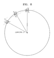
- FIG. 8 illustrates the robot travelling on a circle having the center at the position of a corrected ICR.
- the coordinates and the direction of the robot has moved from the previous position P 1 to a position P 1 ′ on the circle having the center at the position of the corrected ICR. That is, the coordinates and direction of the robot are corrected from the previous position P 1 to the position P 1 ′.
- the coordinates and the direction of the robot has moved from the previous position P 2 to a position P 2 ′ on the circle having the center at the position of the corrected ICR. That is, the coordinates and direction of the robot are corrected from the previous position P 2 to the position P 2 ′.
- the coordinates and the direction of the robot has moved from the previous position P 3 to a position P 3 ′ on the circle having the center at the position of the corrected ICR. That is, the coordinates and direction of the robot are corrected from the previous position P 2 to the position P 2 ′.
- the robot motion is corrected to be on the circle having the center at the position of the corrected ICR, the robot may smoothly travel and an error with respect to an actual travel path may be reduced.
- the coordinate information and direction information on the corrected travel path are used as corrected scan data for the next location change estimation.
- the robot control unit 300 outputs a travel control signal of the robot according to the travel path generated by the location correction unit 200 .
- the drive unit 400 drives the robot to travel according to the travel control signal of the robot control unit 300 .
- FIG. 9 is a block diagram schematically illustrating a structure of a robot system 20 according to another exemplary embodiment.
- the robot system 20 includes the distance measurement unit 100 , a first correction unit 500 , a second correction unit 200 ′, the robot control unit 300 , and the drive unit 400 .
- the second correction unit 200 ′ includes a location change estimation unit 210 ′, a path generation unit 220 ′, a corrected ICR estimation unit 230 ′, and a secondary correction unit 240 ′.
- the accuracy thereof increases as a pair of scan data are close to each other.
- the scan data pair obtained in the initial ICP process is one of the important factors in the ICP algorithm.
- the ICR algorithm may be trapped at a local minimum.
- a starting point of the robot is the closest scan data matching point obtained in the initial ICP process, and an actual matching point is a global minimum position.
- matching may be completed at the local minimum according to the location of the starting point.
- the probability to be trapped at a local minimum increases when starting point 1 and starting point 2 are used.
- the starting point of robot travel needs to be at starting point 3 .
- the first correction unit 500 is used.
- the first correction unit 500 includes an encoder 510 , a gyro sensor 520 , an analysis unit 530 , and a primary correction unit 540 .
- the encoder 510 is attached to a wheel of a robot to detect a travel distance of the robot by counting the number of rotations of the wheel.
- the gyro sensor 520 senses accelerations in both a travel direction of the robot and a direction perpendicular to the travel direction.
- the analysis unit 530 calculates a speed and a rotation angle of the robot by using the travel distance detected by the encoder 510 and a speed and a rotation angle by using the accelerations in both directions sensed by the gyro sensor 520 .
- the primary correction unit 540 calculates an error-corrected speed and rotation angle of the robot by using the speed and rotation angle output from the analysis unit 530 .
- the primary correction unit 540 calculates a location of the robot by using a Kalman filter with respect to the error-corrected speed and rotation angle.
- the location of the robot calculated by the primary correction unit 540 is used as a scan data matching starting point.
- the distance measurement unit 100 measures a relative distance between the distance measurement unit 100 and an object located in front of the distance measurement unit 100 by calculating a turnaround time of a signal such as a laser signal, an infrared ray, an ultrasonic wave, etc. that is emitted by a source device (not shown) of the robot system 20 and returns to the distance measurement unit 100 after being reflected by the object.
- a signal such as a laser signal, an infrared ray, an ultrasonic wave, etc.
- the signal received by the distance measurement unit 100 may be used to obtain scan data which includes a relative distance between the distance measurement unit 100 and the object.
- the second correction unit 200 ′ estimates a location change by matching of a plurality of consecutive scan data pairs by using the scan data matching starting point output from the first correction unit 500 , generates a path of the robot by connecting the respective location changes, estimates a position of a corrected ICR in the vicinity of a plurality of extension lines, each including the ICR of the robot at each position on a travel path, and corrects scan data so that the robot may travel on a circle having the center at the position of the corrected ICR.
- the second correction unit 200 ′ has the same function as the correction unit 200 of FIG. 1 , except for using the scan data matching starting point.
- the location change estimation unit 210 ′ estimates a location change by matching of the consecutive scan data pairs obtained from a space where the robot moves by using an ICP algorithm.
- the path generation unit 220 ′ generates a travel path of the robot by connecting the respective location changes obtained by the location change estimation unit 210 ′.
- the path generation unit 220 ′ sets the location of the robot at a particular time among the location changes as a reference point and generates the travel path of the robot by connecting the location changes with respect to a set reference point.
- the corrected ICR estimation unit 230 ′ estimates the position of a corrected ICR in the vicinity of extensions lines including ICRs from a rotation axis of a robot at the respective positions on a travel path of the robot.
- the corrected ICR estimation unit 230 ′ estimates a point at the closest distance from the extension lines L 1 , L 2 , and L 3 respectively including a first, second and third ICRs ICR 1 , ICR 2 , and ICR 3 from the rotation axis of the robot at the positions P 1 , P 2 , and P 3 , as a position of a corrected ICR, and corrects scan data so that the robot may travel on a circle having the center at the position of the corrected ICR.
- the scan data only the coordinates or direction of the robot may be corrected, and further, both of the coordinates and direction of the robot may be corrected.
- the robot since the travel path of the robot is corrected to be on a circle having the center at the position of the corrected ICR, the robot may smoothly travel and an error with respect to an actual travel path may be reduced.
- the coordinate information and direction information on the corrected travel path are used as corrected scan data for the next location change estimation.
- the first correction unit 500 is not operated in the next location change estimation.
- the robot control unit 300 outputs a travel control signal of the robot according to the travel path generated by the location correction unit 200 .
- the drive unit 400 drives the robot to travel according to the travel control signal of the robot control unit 300 .
- FIG. 11 is a flowchart for explaining a method of driving the robot system 10 according to an exemplary embodiment. In the following description, descriptions that are the same as those with regard to FIGS. 1 through 10 will be omitted.
- the robot system 10 estimates a location change of the robot by matching of a plurality of consecutive scan data pairs obtained from a space where the robot moves (S 10 ).
- the robot system 10 estimates the location change by receiving scan data obtained by measuring a relative distance between the distance measurement unit 100 and an object located in front of the distance measurement unit 100 by calculating a turnaround time of a beam such as a laser beam, an infrared ray, an ultrasonic wave, etc. that is emitted by a source device (not shown) of the robot system 10 and returns to the distance measurement unit 100 after being reflected by the object, and by finding and matching a pair of points located at the closest distance between two consecutive scan data according to the ICP algorithm.
- a beam such as a laser beam, an infrared ray, an ultrasonic wave, etc.
- an accurate matching starting point may be calculated by using the encoder 510 and the gyro sensor 520 .
- the location change of the robot is estimated at time t ⁇ 1, t, and t+1 in the present exemplary embodiment.
- a relative location change of coordinates (x 2 , y 2 ) and a direction ⁇ 2 at the position P 2 with respect to coordinates (x 1 , y 1 ) and a direction ⁇ 1 at the position P 1 including a coordinate change ( ⁇ x 1 , ⁇ y 1 ) and a direction change ⁇ 1 are obtained.
- a relative location change of coordinates (x 3 , y 3 ) and a direction ⁇ 3 at the position P 3 with respect to the coordinates (x 2 , y 2 ) and the direction ⁇ 2 at the position P 2 including a coordinate change ( ⁇ x 2 , ⁇ y 2 ) and a direction change ⁇ 2 , are obtained.
- the location change is estimated.
- the robot system 10 When the estimation of the location change of the robot is completed, the robot system 10 generates a travel path of the robot by connecting the respective location changes (S 20 ).
- the robot system 10 may set the location of the robot at a particular time among the location changes as a reference point and may generate a path of the robot by connecting the location changes with respect to the set reference point. For example, the position P 2 at time t and the position P 3 at time t+1 based on the position P 1 at time t ⁇ 1 may be generated as points on the travel path of the robot.
- the robot system 10 estimates the position of a corrected ICR in the vicinity of a plurality of extension lines, each extension line including an ICR and extending from a rotation axis of the robot at each position on a travel path of the robot (S 30 ).
- the extension line L 1 including a first ICR ICR 1 from the rotation axis of the robot at the position P 1 at time t ⁇ 1 is generated, the extension line L 2 including a second ICR ICR 2 from the rotation axis of the robot at the position P 2 at time t is generated, and the extension line L 2 including a third ICR ICR 3 from the rotation axis of the robot at the position P 3 at time t+1 is generated. Since the extension lines L 1 , L 2 , and L 3 do not meet one another in a single ICR, the travel of the robot is not smooth and an error occurs when compared to an actual travel path. Thus, a point at the closest distance from the extension lines L 1 , L 2 , and L 3 is estimated as the position of a corrected ICR.
- the robot system 10 corrects scan data so that the robot may travel on a circle having the center at the position of the corrected ICR (S 40 ).
- the coordinates and/or direction of the robot may be corrected to a corrected location from a previous location.
- the travel path of the robot since the travel path of the robot is corrected to be a circle having the center at the position of a corrected ICR, the robot may smoothly travels and an error with respect to an actual travel path may be reduced.
- the coordinate information and direction information on the corrected travel path are used as corrected scan data for the next location change estimation.
- the accuracy of estimating a location of a robot may be improved by using the Ackerman steering method to accurately follow a travel path
- the exemplary embodiments can be written as computer programs and can be implemented in general-use digital computers that execute the programs using a computer readable recording medium.
- the computer readable recording medium is any data storage device that can store data which can be thereafter read by a computer system.
- Examples of the computer readable recording medium include read-only memory (ROM), random-access memory (RAM), CD-ROMs, magnetic tapes, floppy disks, optical data storage devices, etc.
- the computer readable recording medium can also be distributed over network coupled computer systems so that the computer readable code is stored and executed in a distributed fashion. (Also, functional programs, codes, and code segments for accomplishing the present invention can be easily construed by programmers skilled in the art to which the present invention pertains.)
Abstract
Description
Claims (19)
Applications Claiming Priority (2)
| Application Number | Priority Date | Filing Date | Title |
|---|---|---|---|
| KR10-2012-0089668 | 2012-08-16 | ||
| KR1020120089668A KR101945734B1 (en) | 2012-08-16 | 2012-08-16 | System for robot and method for driving the same |
Publications (2)
| Publication Number | Publication Date |
|---|---|
| US20140052296A1 US20140052296A1 (en) | 2014-02-20 |
| US9126338B2 true US9126338B2 (en) | 2015-09-08 |
Family
ID=50100614
Family Applications (1)
| Application Number | Title | Priority Date | Filing Date |
|---|---|---|---|
| US13/886,432 Active 2033-11-15 US9126338B2 (en) | 2012-08-16 | 2013-05-03 | Robot system and method for driving the same |
Country Status (2)
| Country | Link |
|---|---|
| US (1) | US9126338B2 (en) |
| KR (1) | KR101945734B1 (en) |
Cited By (3)
| Publication number | Priority date | Publication date | Assignee | Title |
|---|---|---|---|---|
| CN108020855A (en) * | 2017-11-29 | 2018-05-11 | 安徽省通信息科技有限公司 | The pose and instantaneous center of rotation combined estimation method of a kind of glide steering robot |
| WO2018113382A1 (en) * | 2016-12-22 | 2018-06-28 | 北京京东尚科信息技术有限公司 | Method and system for controlling movable device |
| WO2019033712A1 (en) * | 2017-08-18 | 2019-02-21 | 广东宝乐机器人股份有限公司 | Map creation method for mobile robot and path planning method based on map |
Families Citing this family (7)
| Publication number | Priority date | Publication date | Assignee | Title |
|---|---|---|---|---|
| US11282131B2 (en) | 2014-03-31 | 2022-03-22 | Monticello Enterprises LLC | User device enabling access to payment information in response to user input |
| US11080777B2 (en) | 2014-03-31 | 2021-08-03 | Monticello Enterprises LLC | System and method for providing a social media shopping experience |
| US10511580B2 (en) | 2014-03-31 | 2019-12-17 | Monticello Enterprises LLC | System and method for providing a social media shopping experience |
| US10726472B2 (en) | 2014-03-31 | 2020-07-28 | Monticello Enterprises LLC | System and method for providing simplified in-store, product-based and rental payment processes |
| JP6481347B2 (en) * | 2014-11-28 | 2019-03-13 | 村田機械株式会社 | Travel amount estimation device, autonomous mobile body, and travel amount estimation method |
| KR102361641B1 (en) | 2014-12-26 | 2022-02-10 | 삼성전자주식회사 | Method for processing location information and method for processing measurement information including the same |
| CN107421545B (en) * | 2017-08-11 | 2020-09-01 | 广东电网有限责任公司电力科学研究院 | Robot position deviation detection method and device and robot |
Citations (9)
| Publication number | Priority date | Publication date | Assignee | Title |
|---|---|---|---|---|
| US5758298A (en) * | 1994-03-16 | 1998-05-26 | Deutsche Forschungsanstalt Fur Luft-Und Raumfahrt E.V. | Autonomous navigation system for a mobile robot or manipulator |
| US6574361B1 (en) * | 1999-04-12 | 2003-06-03 | Fujitsu Limited | Image measurement method, image measurement apparatus and image measurement program storage medium |
| US20050228539A1 (en) * | 2002-04-26 | 2005-10-13 | Honda Giken Kogyo Kabushiki Kaisha | Control device and footstep determination device for legged mobile robot |
| KR20060072269A (en) | 2004-12-23 | 2006-06-28 | 현대자동차주식회사 | Ackerman tendency control mechanism |
| JP2008020993A (en) | 2006-07-11 | 2008-01-31 | Tookin:Kk | Teaching data preparation device for working robot |
| US7570791B2 (en) | 2003-04-25 | 2009-08-04 | Medtronic Navigation, Inc. | Method and apparatus for performing 2D to 3D registration |
| US20100274387A1 (en) * | 2009-04-24 | 2010-10-28 | Robert Bosch Gmbh | Method of accurate mapping with mobile robots |
| KR101202108B1 (en) | 2010-06-03 | 2012-11-15 | 고려대학교 산학협력단 | Localizing method for mobile robot |
| US8688275B1 (en) * | 2012-01-25 | 2014-04-01 | Adept Technology, Inc. | Positive and negative obstacle avoidance system and method for a mobile robot |
Family Cites Families (1)
| Publication number | Priority date | Publication date | Assignee | Title |
|---|---|---|---|---|
| KR100668788B1 (en) | 2006-05-22 | 2007-01-12 | (주)프리비아 | Position recognition apparatus for mobile robot |
-
2012
- 2012-08-16 KR KR1020120089668A patent/KR101945734B1/en active IP Right Grant
-
2013
- 2013-05-03 US US13/886,432 patent/US9126338B2/en active Active
Patent Citations (12)
| Publication number | Priority date | Publication date | Assignee | Title |
|---|---|---|---|---|
| US5758298A (en) * | 1994-03-16 | 1998-05-26 | Deutsche Forschungsanstalt Fur Luft-Und Raumfahrt E.V. | Autonomous navigation system for a mobile robot or manipulator |
| US6574361B1 (en) * | 1999-04-12 | 2003-06-03 | Fujitsu Limited | Image measurement method, image measurement apparatus and image measurement program storage medium |
| US20050228539A1 (en) * | 2002-04-26 | 2005-10-13 | Honda Giken Kogyo Kabushiki Kaisha | Control device and footstep determination device for legged mobile robot |
| US7570791B2 (en) | 2003-04-25 | 2009-08-04 | Medtronic Navigation, Inc. | Method and apparatus for performing 2D to 3D registration |
| KR20060072269A (en) | 2004-12-23 | 2006-06-28 | 현대자동차주식회사 | Ackerman tendency control mechanism |
| JP2008020993A (en) | 2006-07-11 | 2008-01-31 | Tookin:Kk | Teaching data preparation device for working robot |
| US20100274387A1 (en) * | 2009-04-24 | 2010-10-28 | Robert Bosch Gmbh | Method of accurate mapping with mobile robots |
| US8340818B2 (en) * | 2009-04-24 | 2012-12-25 | Robert Bosch Gmbh | Method of accurate mapping with mobile robots |
| US20130060382A1 (en) * | 2009-04-24 | 2013-03-07 | Robert Bosch Gmbh | Method of accurate mapping with mobile robots |
| US8831778B2 (en) * | 2009-04-24 | 2014-09-09 | Robert Bosch Gmbh | Method of accurate mapping with mobile robots |
| KR101202108B1 (en) | 2010-06-03 | 2012-11-15 | 고려대학교 산학협력단 | Localizing method for mobile robot |
| US8688275B1 (en) * | 2012-01-25 | 2014-04-01 | Adept Technology, Inc. | Positive and negative obstacle avoidance system and method for a mobile robot |
Non-Patent Citations (1)
| Title |
|---|
| Kim, Min-Sik, "A Study on Guidance Method of Pedestrian Assistant Robot for the Elderly," Information and Communication Technology, Technology and Energy, Korea Polytechnic University, 2005, 12, pp. 1-53. |
Cited By (7)
| Publication number | Priority date | Publication date | Assignee | Title |
|---|---|---|---|---|
| WO2018113382A1 (en) * | 2016-12-22 | 2018-06-28 | 北京京东尚科信息技术有限公司 | Method and system for controlling movable device |
| US11300973B2 (en) | 2016-12-22 | 2022-04-12 | Beijing Jingdong Qianshi Technology Co., Ltd. | Control method and system of movable device |
| WO2019033712A1 (en) * | 2017-08-18 | 2019-02-21 | 广东宝乐机器人股份有限公司 | Map creation method for mobile robot and path planning method based on map |
| JP2020529061A (en) * | 2017-08-18 | 2020-10-01 | グワンドン ボナ ロボット コーポレーション リミテッド | Map creation method for mobile robots and route planning method based on the map |
| US11385062B2 (en) | 2017-08-18 | 2022-07-12 | Guangzhou Coayu Robot Co., Ltd. | Map creation method for mobile robot and path planning method based on the map |
| CN108020855A (en) * | 2017-11-29 | 2018-05-11 | 安徽省通信息科技有限公司 | The pose and instantaneous center of rotation combined estimation method of a kind of glide steering robot |
| CN108020855B (en) * | 2017-11-29 | 2020-01-31 | 安徽省一一通信息科技有限公司 | posture and rotation instantaneous center joint estimation method for skid-steer robot |
Also Published As
| Publication number | Publication date |
|---|---|
| KR20140023608A (en) | 2014-02-27 |
| US20140052296A1 (en) | 2014-02-20 |
| KR101945734B1 (en) | 2019-02-11 |
Similar Documents
| Publication | Publication Date | Title |
|---|---|---|
| US9126338B2 (en) | Robot system and method for driving the same | |
| CN112985416B (en) | Robust positioning and mapping method and system based on laser and visual information fusion | |
| US10275649B2 (en) | Apparatus of recognizing position of mobile robot using direct tracking and method thereof | |
| US9386209B2 (en) | Method and apparatus for estimating position | |
| US9274526B2 (en) | Autonomous vehicle and method of estimating self position of autonomous vehicle | |
| US8515612B2 (en) | Route planning method, route planning device and autonomous mobile device | |
| KR101738750B1 (en) | Method and apparatus for robust localization in outdoor environments | |
| US10307910B2 (en) | Apparatus of recognizing position of mobile robot using search based correlative matching and method thereof | |
| US20170151675A1 (en) | Apparatus for recognizing position of mobile robot using edge based refinement and method thereof | |
| JP6349418B2 (en) | Object positioning by high-precision monocular movement | |
| JP4697127B2 (en) | Self-position recognition method | |
| JP6827642B2 (en) | Self-calibration sensor system for vehicles with wheels | |
| CN110345936B (en) | Track data processing method and processing system of motion device | |
| US11814056B2 (en) | Travel amount estimation apparatus | |
| CN112987734B (en) | Robot travel method, robot travel device, electronic device, storage medium, and program product | |
| KR20200030738A (en) | Moving robot and method for estiating location of moving robot | |
| KR20200028648A (en) | Method for adjusting an alignment model for sensors and an electronic device performing the method | |
| US11912272B2 (en) | Target track generation apparatus, vehicle control apparatus, target track generation method, and vehicle control method | |
| JP2019199160A (en) | Travel trajectory recognition device, travel trajectory recognition method, vehicle control device, and vehicle control method | |
| JP2019073192A (en) | Estimation device and parking support apparatus | |
| KR101738751B1 (en) | Method and apparatus for localization of mobile robot using indoor magnetic field | |
| JP6589578B2 (en) | Travel amount estimation device, autonomous mobile body, and travel amount estimation method | |
| US11662742B2 (en) | Self-position estimation method | |
| US10794696B2 (en) | Method for identifying noise data of laser ranging device | |
| JP5723182B2 (en) | Autonomous mobile object, autonomous mobile object orientation correction method, and autonomous mobile object orientation correction program |
Legal Events
| Date | Code | Title | Description |
|---|---|---|---|
| AS | Assignment |
Owner name: SAMSUNG TECHWIN CO., LTD., KOREA, REPUBLIC OF Free format text: ASSIGNMENT OF ASSIGNORS INTEREST;ASSIGNORS:LEE, JIN-HAN;KIM, YANG-HYUN;KIM, KI-SUNG;REEL/FRAME:030344/0408 Effective date: 20130430 |
|
| AS | Assignment |
Owner name: HANWHA TECHWIN CO., LTD., KOREA, REPUBLIC OF Free format text: CHANGE OF NAME;ASSIGNOR:SAMSUNG TECHWIN CO., LTD.;REEL/FRAME:036254/0911 Effective date: 20150701 |
|
| STCF | Information on status: patent grant |
Free format text: PATENTED CASE |
|
| FEPP | Fee payment procedure |
Free format text: PAYOR NUMBER ASSIGNED (ORIGINAL EVENT CODE: ASPN); ENTITY STATUS OF PATENT OWNER: LARGE ENTITY |
|
| MAFP | Maintenance fee payment |
Free format text: PAYMENT OF MAINTENANCE FEE, 4TH YEAR, LARGE ENTITY (ORIGINAL EVENT CODE: M1551); ENTITY STATUS OF PATENT OWNER: LARGE ENTITY Year of fee payment: 4 |
|
| AS | Assignment |
Owner name: HANWHA AEROSPACE CO., LTD., KOREA, REPUBLIC OF Free format text: CHANGE OF NAME;ASSIGNOR:HANWHA TECHWIN CO., LTD.;REEL/FRAME:048478/0831 Effective date: 20180401 |
|
| AS | Assignment |
Owner name: HANWHA PRECISION MACHINERY CO., LTD., KOREA, REPUB Free format text: ASSIGNMENT OF ASSIGNORS INTEREST;ASSIGNOR:HANWHA AEROSPACE CO., LTD.;REEL/FRAME:048853/0048 Effective date: 20190329 Owner name: HANWHA PRECISION MACHINERY CO., LTD., KOREA, REPUBLIC OF Free format text: ASSIGNMENT OF ASSIGNORS INTEREST;ASSIGNOR:HANWHA AEROSPACE CO., LTD.;REEL/FRAME:048853/0048 Effective date: 20190329 |
|
| AS | Assignment |
Owner name: HANWHA CO., LTD., KOREA, REPUBLIC OF Free format text: ASSIGNMENT OF ASSIGNORS INTEREST;ASSIGNOR:HANWHA PRECISION MACHINERY CO., LTD.;REEL/FRAME:054273/0475 Effective date: 20201015 |
|
| MAFP | Maintenance fee payment |
Free format text: PAYMENT OF MAINTENANCE FEE, 8TH YEAR, LARGE ENTITY (ORIGINAL EVENT CODE: M1552); ENTITY STATUS OF PATENT OWNER: LARGE ENTITY Year of fee payment: 8 |
|
| AS | Assignment |
Owner name: HANWHA ROBOTICS CORPORATION, KOREA, REPUBLIC OF Free format text: ASSIGNMENT OF ASSIGNORS INTEREST;ASSIGNOR:HANWHA CO., LTD.;REEL/FRAME:065779/0594 Effective date: 20231128 |