US9122946B2 - Systems, methods, and media for capturing scene images and depth geometry and generating a compensation image - Google Patents
Systems, methods, and media for capturing scene images and depth geometry and generating a compensation image Download PDFInfo
- Publication number
- US9122946B2 US9122946B2 US12/161,415 US16141507A US9122946B2 US 9122946 B2 US9122946 B2 US 9122946B2 US 16141507 A US16141507 A US 16141507A US 9122946 B2 US9122946 B2 US 9122946B2
- Authority
- US
- United States
- Prior art keywords
- scene
- radiance
- pixels
- pixel
- defocus
- Prior art date
- Legal status (The legal status is an assumption and is not a legal conclusion. Google has not performed a legal analysis and makes no representation as to the accuracy of the status listed.)
- Active, expires
Links
Images


Classifications
-
- G06K9/2036—
-
- G—PHYSICS
- G06—COMPUTING; CALCULATING OR COUNTING
- G06V—IMAGE OR VIDEO RECOGNITION OR UNDERSTANDING
- G06V10/00—Arrangements for image or video recognition or understanding
- G06V10/10—Image acquisition
- G06V10/12—Details of acquisition arrangements; Constructional details thereof
- G06V10/14—Optical characteristics of the device performing the acquisition or on the illumination arrangements
- G06V10/145—Illumination specially adapted for pattern recognition, e.g. using gratings
-
- G06K2209/401—
-
- G—PHYSICS
- G06—COMPUTING; CALCULATING OR COUNTING
- G06V—IMAGE OR VIDEO RECOGNITION OR UNDERSTANDING
- G06V2201/00—Indexing scheme relating to image or video recognition or understanding
- G06V2201/12—Acquisition of 3D measurements of objects
- G06V2201/121—Acquisition of 3D measurements of objects using special illumination
Definitions
- the disclosed subject matter relates to systems, methods, and media for capturing scene images and depth geometry and generating a compensation image.
- Digital projection technologies such as Digital Light Processing (DLP) and Liquid Crystal Displays (LCD) are increasingly used in many non-traditional consumer, commercial and scientific applications.
- DLP Digital Light Processing
- LCD Liquid Crystal Displays
- computer graphics and vision for instance, video projectors have recently been used as per-pixel controllable light sources for real-time shape acquisition and for complex appearance capture and control.
- Most of these applications require a projector to be focused for best performance.
- virtually all projectors are built with large apertures to maximize their brightness at the expense of narrower depths of field, and thus are designed to produce focused images on a single fronto-parallel screen, i.e., the traditional application for the projector.
- Pixelation can be caused by two factors. The first is spatial digitization due to the finite resolution of the digital projectors. The second is the gap between adjacent pixels on the digital projector's physical image plane that arises because the pixel fill-factor is never complete. Pixelation tends to mark out pixel boundaries more distinctly when the resolution of images to be projected is much higher than the resolution of the digital projectors that are used to project the images.
- systems, methods, and media for capturing scene images and depth geometry and generating a compensation image comprising a projector, an optical sensor, and a digital processing device.
- the projector is capable of being defocused with respect to a scene and projects light having a shifting periodic illumination pattern on the scene.
- the optical sensor has a plurality of pixels and detects a portion of the radiance of at least one image of the scene at each of the pixels.
- the digital processing device is capable of being coupled to the optical sensor and obtains a temporal radiance profile from the radiance over a time period for each of the pixels, determines an amount of projection defocus at each of the of pixels using the temporal radiance profile, and, at each of the pixels, computes a depth to the scene at the pixel using the amount of projection defocus at the pixel.
- systems for generating a compensation image comprising a projector, an optical sensor, and a digital processing device.
- the projector projects an image to a projection structure.
- the optical sensor has a plurality of pixels that detect a portion of the radiance of the image at each of the pixels.
- the digital processing device is capable of being coupled to the optical sensor and the projector, and computes a defocus kernel for each of the pixels and generates a compensation image using the radiance and the defocus kernel.
- methods for capturing scene images and depth geometry project a defocused image having a shifting periodic illumination pattern on a scene, detect a portion of the radiance of the defocused image at each of a plurality of pixels, obtain a temporal radiance profile from the radiance over a time period for each of the pixels, determine an amount of projection defocus at each of the pixels using the temporal radiance profile, and compute depth to the scene at each of the pixels using the determined amount of projection defocus.
- methods for generating a compensation image are provided. These methods project an image, detect a portion of the radiance of the image at each of a plurality of pixels, compute a defocus kernel for each of the pixels, and generate a compensation image using the radiance and the defocus kernel.
- computer-readable media containing computer-executable instructions that, when executed by a processor, cause the processor to perform a method for capturing scene images and depth geometry.
- the method projects a defocused image having a shifting periodic illumination pattern on a scene, detects a portion of the radiance of the defocused image at each of a plurality of pixels, obtains a temporal radiance profile from the radiance over a time period for each of the pixels, determines an amount of projection defocus at each of the pixels using the temporal radiance profile, and computes depth to the scene at each of the pixels using the determined amount of projection defocus.
- computer-readable media containing computer-executable instructions that, when executed by a processor, cause the processor to perform a method for generating a compensation image are provided.
- the method projects an image, detects a portion of the radiance of the image at each of a plurality of pixels, computes a defocus kernel for each of the pixels, and generates a compensation image using the radiance and the defocus kernel.
- systems for capturing scene images and depth geometry include means for projecting a defocused image having a shifting periodic illumination pattern on a scene, means for capturing a portion of the radiance of the defocused image at each of a plurality of pixels, means for obtaining a temporal radiance profile from the radiance over a time period for each of the pixels, means for measuring an amount of projection defocus at each of the pixels using the temporal radiance profile, and means for estimating depth to the scene at each of the pixels using the determined amount of projection defocus.
- systems for generating a compensation image include means for projecting an image, means for capturing a portion of the radiance of the image at each of a plurality of pixels, means for estimating a defocus kernel for each of the pixels, and means for calculating a compensation image using the radiance and the defocus kernel.
- FIG. 1 is a schematic diagram of a system for recovering depth at each pixel of an optical sensor using defocus properties of a projector in accordance with some embodiments of the disclosed subject matter.
- FIG. 2 is an illustration of a principle behind estimating depth of each point within a scene by obtaining a temporal radiance profile for each point in accordance with some embodiments of the disclosed subject matter.
- FIGS. 3A-D are illustrations of temporal radiance profiles obtained at points at different distances from the projection plane of a projector over a time period in accordance with some embodiments of the disclosed subject matter.
- FIG. 4 is a simple illustration of a method for generating and using a depth map of a scene in accordance with some embodiments of the disclosed subject matter.
- FIG. 5 is an illustrative diagram for estimating corresponding depths for different amounts of determined projection defocus in accordance with some embodiments of the disclosed subject matter.
- FIG. 6 is a graphical illustration of inserting an object into an image captured from a scene using its depth map in accordance with some embodiments of the disclosed subject matter.
- FIG. 7A is a schematic diagram of a system for compensating for projection defocus based on projection surface geometry in accordance with some embodiments of the disclosed subject matter.
- FIG. 7B is an illustration of a dot pattern used for estimating a defocus kernel for each pixel of an optical sensor in accordance with some embodiments of the disclosed subject matter.
- FIG. 8 is a simple illustration of a method for compensating for projection defocus in accordance with some embodiments of the disclosed subject matter.
- FIG. 9 is a schematic diagram of a system for compensating for pixelation artifacts in accordance with some embodiments of the disclosed subject matter.
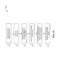
- FIG. 10 is a simple illustration of a method for compensating for pixelation artifacts in accordance with some embodiments of the disclosed subject matter.
- systems, methods, and media for capturing scene images and depth geometry and generating a compensation image are provided.
- systems, methods, and media are provided for estimating depth at a projection surface for each pixel of an optical sensor through a temporal defocus analysis.
- Light containing a structured pattern is projected onto a scene and a portion of the resulting scene radiance is detected.
- a simple linear model for a surface point of the scene can be used to represent projector defocus.
- the projected pattern is the input and the scene radiance is the output.
- a defocus kernel for a surface point of the scene is a filter that represents an amount of defocus blur experienced by the point and can be computed at each pixel of an optical sensor, such as a digital camera.
- the output of the linear model is the response of the surface point's defocus kernel to the input over time. Because the defocus kernel depends on the distance between the point and a projector lens, the depth at each pixel of an optical sensor can be computed using intensity variation of a projected shifting pattern over time.
- FIG. 1 is a schematic diagram of a system 100 for recovering depth at each pixel of an optical sensor using defocus properties of a projector in accordance with some embodiments of the disclosed subject matter.
- system 100 includes a projector 102 , a beam-splitter 104 , an optical sensor 106 , and a digital processing device 108 .
- Projector 102 projects light 112 A containing a structured pattern 116 onto a scene 114 having objects 110 A-C that are placed at different distances from the lens of projector 102 .
- Light 112 A can be focused behind scene 114 or in front of scene 114 .
- Projector 102 can be a commercially available projector, such as an NEC LT260K DLP projector, or any other suitable device for projecting images or light containing a structured pattern, such as structured pattern 116 .
- Optical sensor 106 can be a commercially available camera, such as a Basler A311f monochrome camera, or any other suitable device for capturing images of a scene.
- Beam-splitter 104 can be a simple half-mirror, a commercially available splitter, such as an Edmund Optics #NT39-493 beam splitter, or any other suitable device for passing incoming light from one direction while reflecting incoming light from the opposite direction.
- beam-splitter is placed in a custom-designed chamber that absorbs all forms of stray light to reduce the effect of light from the backdrop.
- Digital processing device 108 can be a microprocessor, digital signal processor, video processor, or any other suitable device for processing and/or storing data.
- optical sensor 106 is a camera
- the aperture of the camera is stopped down to F11 so that the camera works approximately as a pinhole camera, thereby any defocus introduced by the camera is negligible compared to that of projector 102 where projector 102 is quite bright.
- Equation (1) defines a linear model in which light 112 A containing structured pattern 116 is the input and the scene radiance is the output.
- the defocus kernel depends on the depth of the scene, z, and, therefore, the depth can be recovered from the defocus kernel, which, in turn, can be computed from the determined scene radiance.
- the radiance at each point within scene 114 then is the response of its defocus kernel to the excitation by structured pattern 116 .
- projector 102 and optical sensor 106 can be arranged in optically coaxial configuration where optical sensor 106 and projector 102 share the same optical center such that the depth can be computed at all pixels of optical sensor 106 without missing any part of the scene. Shadows and occlusions can be also avoided by using such coaxial configuration.
- FIGS. 1 , 2 , 3 A-D, and 4 are now referenced together to illustrate methods to capture images of a scene while preserving the scene's depth geometry.
- projector 102 is focused at a point 202 , which is located behind scene 114 having objects 110 A-C. Focusing projector 102 behind scene 114 causes light 112 A projected onto scene 114 to be blurred from projection defocus, and avoids a two-way defocus ambiguity.
- light 112 A is projected onto scene 114 such that structured pattern 116 is shifted across scene 114 .
- structured pattern 116 can be a binary periodic sequence, such as 011011011011 . . . that is encoded as a stripe pattern. In other embodiments, structured pattern 116 can be encoded in different patterns.
- the binary periodic sequence has a period of three and each bit in the stripe pattern corresponds to an eight-pixel-wide stripe. In other embodiments, the binary sequence period can be smaller or larger and the stripe pattern can correspond to a wider or narrower stripe.
- structured pattern 116 is shifted one pixel at a time and a total of 24 images of scene 114 are taken. In other embodiments, structure pattern 116 can be shifted at different rates and different numbers of images can be taken.
- the radiance of each surface point within scene 114 is detected at each pixel of optical sensor 106 over a period of time to obtain temporal radiance profile for each surface point.
- light 112 A having structured pattern 116 is shifted across scene 114 , it appears more blurred when it crosses object 110 A than when it crosses object 110 B or object 110 C (as represented by blurred sections 113 A, 113 B, and 113 C), because object 110 B and 110 C are closer to focus plane 216 of projector 102 , i.e., structured pattern 116 is better focused when it crosses object 110 B or object 110 C.
- FIG. 2 illustrates this in more detail.
- Three points 204 , 206 , and 208 which correspond to surface points of objects 110 C, 110 B, and 110 A, respectively, are located at different distances from focus point 202 on focus plane 216 with a lens 210 through which light having a structured pattern 212 is projected.
- the light projected onto focus point 202 of projector 102 experiences no projection defocus and its radiance is equivalent to the projected light as shown in FIG. 3A .
- the light projected onto point 204 is not focused and thus experiences projection defocus as indicated on projection plane 214 and its radiance is diminished as shown in FIG. 3B .
- the light projected onto point 206 experiences greater amount of projection defocus because it is further away from focus plane 216 and its radiance is further diminished as shown in FIG. 3C .
- the radiance of point 208 suffers from even greater amount of projection defocus and the resulting blurs.
- FIG. 1 also shows different amount of projection defocus experienced by objects 110 A-C that are at different distance from focus plane 216 , which is placed behind scene 114 .
- Light 112 A projected onto focus plane 216 appears sharp and focused. As light 112 A is shifted across the scene, it falls upon objects 110 A-C. Because objects 110 A-C are located outside the depth of field of projector 102 , and hence are out of focus, projected light 112 B-D falling on objects 110 A-C becomes blurred.
- Projected light 112 B which falls on object 110 A appears blurrier than projected light 112 C or 112 D (again, as represented by blurred sections 113 A, 113 B, and 113 C), which falls on object 110 B and object 110 C, respectively, because object 110 A lies furthest from projector's 102 focus plane 216 of projector 102 .
- the strength of the temporal radiance profile of a point within scene 114 as shown in FIGS. 3A-D , varies depending on the extent to which the projected light 112 A-D is defocused.
- the amount of projection defocus is determined for each pixel of optical sensor 106 .
- a frequency domain approach is used to determine the amount of projection defocus. For example, given the temporal radiance profile of a point within scene 114 , projection defocus at the point, i.e., blurriness, can be quantized by decomposing the temporal radiance profile of the point into a discrete-time Fourier series represented as Equation (2):
- the depth of the scene at each pixel of optical sensor 106 is computed using the amount of projection defocus computed for each pixel. In some embodiments, this is achieved by calibrating the mapping of the ⁇ in Equation (3) to the depth.
- FIG. 5 which is an illustrative diagram for estimating corresponding depths for different amounts of determined projection defocus, is referenced to illustrate how calibration of the mapping of the ⁇ to the depth can be achieved.
- the correspondence between pixels of projector 102 and pixels of optical sensor 106 is computed. This is realized by projecting shifted sinusoids in both horizontal and vertical directions. This technique is described in detail by Scharstein et al., (2003) Proc. IEEE Conf. on Computer Vision and Pattern Recognition, 195-202, the content of which is herein incorporated by reference in its entirety.
- the ⁇ values for all points on surface 502 can be computed by shifting light 504 containing a structured pattern, such as structured pattern 116 across surface 502 and computing the first two coefficients from the discrete Fourier series of the temporal radiance profile for each pixel of optical sensor 106 .
- the mapping of the computed depth to the computed ⁇ is then tabulated in a lookup table for each pixel or for each column.
- captured images of scene 114 can be enhanced using depth map 118 .
- an image captured from a scene and a depth map that segments the scene into layers can be used to generate images that are focused at any desired depth. For instance, an image captured from scene 114 having three objects 110 A-C and depth map 118 that segments scene 114 into three different layers can be used to create a refocused image that is focused at each of objects 110 A-C.
- additional objects can be inserted into the original image with correct occlusion effects by editing the original image using its depth map as a reference.
- FIG. 6 is a graphical illustration of inserting an object into an image captured from a scene using its depth map in accordance with some embodiments of the disclosed subject matter.
- a depth map 604 for a scene 602 containing five poker cards arranged in multiple depth layers can be used to generate a new image 608 by inserting a triangle 606 into scene 602 between the first and second layers of the poker cards.
- triangle 606 can be inserted into image 602 with correct occlusion effects.
- Other possible enhancements include creating layered representations of complex scenes for view morphing, segmentation of matting, object replacement, and shadow removal.
- digital processing device 708 is coupled to projector 702 and optical sensor 706 .
- projector 702 and optical sensor 706 are arranged in optically coaxial configuration where optical sensor 706 and projector 702 share the same optical center.
- Non-planar projection structure 710 can be a structure having multiple surfaces of varying depth, a dome, or any other structure with suitable geometry.
- FIG. 8 is a simple illustration of a method 800 for compensating for projection defocus.
- an input image is projected on a projection structure, such as non-planar projection structure 710 .
- the radiance of a point on the surface due to illumination by the projector 702 can be represented by the projection defocus equation, Equation (1).
- the scene radiance of the projected image is detected at each pixel of optical sensor 706 .
- Optical sensor 706 is used as a proxy for the human eye.
- Method 800 attempts to make the scene radiance detected by optical sensor 706 be the same as the input image by projecting a compensation image.
- the defocus kernel at each pixel of optical sensor 706 is computed.
- the ambient term, ⁇ is obtained by turning off projector 702 and taking an image.
- projector 702 can project a dot pattern, such as the one illustrated in FIG. 7B , across projection structure 708 over a period of time as optical sensor 706 detects the radiance of the dot pattern from projection structure 710 at each pixel of optical sensor 706 .
- the temporal radiance profile for each pixel of optical sensor 606 that is obtained by digital processing device 708 can be used as the defocus kernel of each pixel.
- the compensation image is generated using the detected radiance and the computed defocus kernel.
- the problem of computing the compensation image is cast as a constrained minimization problem represented by Equation (5):
- Equation (5) finds the compensation image, P*, with all brightness values within the dynamic range of projector 702 , that most closely matches the input image, I.
- the sum-of-squares pixel difference is used for implementing the image distance matrix, d( ⁇ , ⁇ ).
- the compensation image can be found by applying an iterative, constrained, steepest-descent algorithm wherein the defocus convolution, ⁇ f*P, is represented as a matrix multiplication, FP, where each row of F is the defocus kernel of the corresponding pixel modulated by its albedo.
- Equation (6) is a standard steepest-descent algorithm that converges to the solution of Equation (4). Combining Equation (6) and Equation (7), however, minimizes the difference between the defocused compensation image and the original input image with the dynamic range of projector 702 .
- the compensation image can be projected on the projection surface.
- FIGS. 9 and 10 are now referenced together to illustrate methods for compensating pixelation artifacts.
- FIG. 9 a schematic diagram of a system 900 for compensating for pixelation artifacts in accordance with some embodiments.
- system 900 includes a projector 902 , a beam-splitter 904 , an optical sensor 906 , and a digital processing device 908 .
- Projector 902 , beam-splitter 904 , optical sensor 906 , and digital processing device 908 may be the same or substantially similar to projector 102 , beam-splitter 104 , optical sensor 106 , and digital processing device 108 in FIG. 1 .
- Projector 902 is used to project images onto a single fronto-parallel screen 910 , i.e., a traditional projection surface.
- digital processing device 908 is coupled to projector 902 and optical sensor 906 .
- beam-splitter 904 projector 902 and optical sensor 906 are arranged in optically coaxial configuration where optical sensor 906 and projector 902 share the same optical center.
- FIG. 10 is a simple illustration of a method 1000 for compensating for pixelation artifacts.
- an image suffering from pixelation artifacts 912 is projected on the projection screen 910 .
- projector 902 is defocused by focusing projector 902 slightly in front of, or behind, projection screen 910 so that the image on projection screen 910 is slightly blurred, thereby causing a slight amount of light to leak into the dead zone between pixels.
- the image now suffers from projection defocus and the resulting blurring effects. But, since the induced blur is very slight, it can be compensated for.
- the scene radiance of the image projected by defocused projector 902 is detected by optical sensor 906 at each pixel.
- the defocus kernel at each pixel can be computed in the same or substantially the same manner as is described in connection with 806 of FIG. 8 .
- a compensation image is generated using the detected radiance and the computed kernel for each pixel of optical sensor 906 in the same or substantially the same manner as is described in connection with 808 of FIG. 8 .
- the compensation image can be projected onto projection screen 910 .
Abstract
Description
I=αf(x;z)·P(x)+β,
where · denotes convolution, α is a factor depending on surface reflectance, β is the radiance due to the ambient light, f(x; z) is the defocus kernel, x is a projector pixel coordinate, and P(x) is a mathematical representation of structured
Because the defocus kernel f(x; z) is a low-pass filter, how quickly the coefficients Ak diminish with k is a measure of the amount of defocus, which in turn is used to compute the depth at the point. Though A0 cannot be used to compute the depth because it depends on the ambient light, β, and all the remaining coefficients are scaled by albedo, α, the ratio of the first two coefficients, A1 and A2, can be used to determine how severely the projection defocus attenuates the second-order harmonic with respect to the first-order harmonic. Therefore, the depth can be determined using the ratio of A1 and A2 represented as Equation (3):
θ=A 2 /A 1,
where A1>A2>0 and θε[0,1].
P*=(αf)−1·(I−β),
where (αf)−1 is the inverse of the kernel, αf.
where x is the coordinates of pixels in
{tilde over (P)} i+1 =P i+ηi G I
P i+1=CLAMP({tilde over (P)} i+1;0,255)
where Gi=FT(I−β−FPi), ηi=∥Gi∥2/∥FGi∥2, and CLAMP is a pixel-wise clamping operation. Gi is the gradient of the image distance ∥PF+β−I∥2 with respect to P. Evaluating Gi involves two image filterings with the kernel matrices F and FT, respectively. These filterings are spatially varying and scene-dependent. Equation (6) is a standard steepest-descent algorithm that converges to the solution of Equation (4). Combining Equation (6) and Equation (7), however, minimizes the difference between the defocused compensation image and the original input image with the dynamic range of
Claims (26)
Priority Applications (1)
| Application Number | Priority Date | Filing Date | Title |
|---|---|---|---|
| US12/161,415 US9122946B2 (en) | 2006-01-24 | 2007-01-24 | Systems, methods, and media for capturing scene images and depth geometry and generating a compensation image |
Applications Claiming Priority (3)
| Application Number | Priority Date | Filing Date | Title |
|---|---|---|---|
| US76197706P | 2006-01-24 | 2006-01-24 | |
| US12/161,415 US9122946B2 (en) | 2006-01-24 | 2007-01-24 | Systems, methods, and media for capturing scene images and depth geometry and generating a compensation image |
| PCT/US2007/002056 WO2007087405A2 (en) | 2006-01-24 | 2007-01-24 | Capturing scene images and depth geometry and generating a compensation image |
Publications (2)
| Publication Number | Publication Date |
|---|---|
| US20090244090A1 US20090244090A1 (en) | 2009-10-01 |
| US9122946B2 true US9122946B2 (en) | 2015-09-01 |
Family
ID=38309852
Family Applications (1)
| Application Number | Title | Priority Date | Filing Date |
|---|---|---|---|
| US12/161,415 Active 2029-02-02 US9122946B2 (en) | 2006-01-24 | 2007-01-24 | Systems, methods, and media for capturing scene images and depth geometry and generating a compensation image |
Country Status (3)
| Country | Link |
|---|---|
| US (1) | US9122946B2 (en) |
| JP (1) | JP2009524849A (en) |
| WO (1) | WO2007087405A2 (en) |
Cited By (2)
| Publication number | Priority date | Publication date | Assignee | Title |
|---|---|---|---|---|
| US11525671B2 (en) | 2017-12-12 | 2022-12-13 | Samsung Electronics Co., Ltd. | High contrast structured light patterns for QIS sensors |
| US11551367B2 (en) | 2017-12-12 | 2023-01-10 | Samsung Electronics Co., Ltd. | Ultrafast, robust and efficient depth estimation for structured-light based 3D camera system |
Families Citing this family (23)
| Publication number | Priority date | Publication date | Assignee | Title |
|---|---|---|---|---|
| US7794090B2 (en) * | 2006-01-24 | 2010-09-14 | Seiko Epson Corporation | Efficient dual photography |
| US8693742B2 (en) | 2008-12-17 | 2014-04-08 | The Regents Of The University Of Colorado | Three-dimensional single-molecule fluorescence imaging beyond the diffraction limit using a double-helix point spread function |
| JP5760324B2 (en) * | 2010-03-19 | 2015-08-05 | ソニー株式会社 | Image processing apparatus, image processing method, image processing program, and recording medium on which the image processing program is recorded |
| KR101789071B1 (en) * | 2011-01-13 | 2017-10-24 | 삼성전자주식회사 | Apparatus and method for extracting feature of depth image |
| US8976256B2 (en) * | 2011-03-21 | 2015-03-10 | The United States Of America As Represented By The Secretary Of The Air Force | Remote sensing of hidden objects |
| US9100574B2 (en) | 2011-10-18 | 2015-08-04 | Hewlett-Packard Development Company, L.P. | Depth mask assisted video stabilization |
| EP2864468B1 (en) | 2012-06-22 | 2020-08-05 | The Regents of the University of Colorado, a body corporate | Method and system for estimating a position and an angular orientation of a particle |
| US8896594B2 (en) * | 2012-06-30 | 2014-11-25 | Microsoft Corporation | Depth sensing with depth-adaptive illumination |
| WO2014144820A1 (en) | 2013-03-15 | 2014-09-18 | The Regents Of The University Of Colorado | 3-d localization and imaging of dense arrays of particles |
| US9696145B2 (en) * | 2013-05-13 | 2017-07-04 | Texas Instruments Incorporated | Opportunistic structured light |
| CN105247567B (en) | 2013-05-30 | 2019-06-21 | 诺基亚技术有限公司 | A kind of image focusing device, method, system and non-transient program storage device again |
| US10036735B2 (en) | 2013-08-26 | 2018-07-31 | The Regents Of The University Of Colorado, A Body Corporate | Imaging through scattering media with high signal to noise ratio and resolution |
| WO2016073785A1 (en) * | 2014-11-05 | 2016-05-12 | The Regents Of The University Of Colorado | 3d imaging, ranging, and/or tracking using active illumination and point spread function engineering |
| WO2016157671A1 (en) * | 2015-03-27 | 2016-10-06 | ソニー株式会社 | Information processing device, information processing method, program, and image display device |
| US10409031B2 (en) * | 2015-11-18 | 2019-09-10 | Maxell, Ltd. | Image projection apparatus |
| JP2020521149A (en) * | 2017-03-29 | 2020-07-16 | エンゲンマ オーワイ | Gemological object recognition |
| TWI672938B (en) * | 2017-03-31 | 2019-09-21 | 鈺立微電子股份有限公司 | Depth map generation device capable of calibrating occlusion |
| WO2019058415A1 (en) * | 2017-09-19 | 2019-03-28 | Necディスプレイソリューションズ株式会社 | Multi-projection system, image projecting method, and projector |
| WO2019064968A1 (en) | 2017-09-29 | 2019-04-04 | 富士フイルム株式会社 | Projection device and projection method |
| WO2019167455A1 (en) * | 2018-03-02 | 2019-09-06 | ソニー株式会社 | Information processing device, calculation method for information processing device, program |
| JP7287390B2 (en) * | 2018-05-28 | 2023-06-06 | ソニーグループ株式会社 | Image processing device, image processing method |
| JP6664532B2 (en) * | 2019-04-24 | 2020-03-13 | マクセル株式会社 | Image projection device |
| JP2023503517A (en) * | 2019-11-27 | 2023-01-30 | トリナミクス ゲゼルシャフト ミット ベシュレンクテル ハフツング | Depth measurement with display |
Citations (9)
| Publication number | Priority date | Publication date | Assignee | Title |
|---|---|---|---|---|
| US4653104A (en) | 1984-09-24 | 1987-03-24 | Westinghouse Electric Corp. | Optical three-dimensional digital data acquisition system |
| US5447811A (en) * | 1992-09-24 | 1995-09-05 | Eastman Kodak Company | Color image reproduction of scenes with preferential tone mapping |
| JPH1183454A (en) | 1997-09-10 | 1999-03-26 | Citizen Watch Co Ltd | Three-dimensional shape measuring device using grid pattern projection method |
| US6229913B1 (en) * | 1995-06-07 | 2001-05-08 | The Trustees Of Columbia University In The City Of New York | Apparatus and methods for determining the three-dimensional shape of an object using active illumination and relative blurring in two-images due to defocus |
| US20030068098A1 (en) * | 2001-09-27 | 2003-04-10 | Michael Rondinelli | System and method for panoramic imaging |
| US20030103047A1 (en) * | 1996-06-05 | 2003-06-05 | Alessandro Chiabrera | Three-dimensional display system: apparatus and method |
| US20040056966A1 (en) | 2000-07-21 | 2004-03-25 | Schechner Yoav Y. | Method and apparatus for image mosaicing |
| JP2005225111A (en) | 2004-02-13 | 2005-08-25 | Seiko Epson Corp | Writing device |
| JP2005291839A (en) | 2004-03-31 | 2005-10-20 | Brother Ind Ltd | Projecting device and three-dimensional shape detection device |
-
2007
- 2007-01-24 JP JP2008552409A patent/JP2009524849A/en active Pending
- 2007-01-24 US US12/161,415 patent/US9122946B2/en active Active
- 2007-01-24 WO PCT/US2007/002056 patent/WO2007087405A2/en active Application Filing
Patent Citations (9)
| Publication number | Priority date | Publication date | Assignee | Title |
|---|---|---|---|---|
| US4653104A (en) | 1984-09-24 | 1987-03-24 | Westinghouse Electric Corp. | Optical three-dimensional digital data acquisition system |
| US5447811A (en) * | 1992-09-24 | 1995-09-05 | Eastman Kodak Company | Color image reproduction of scenes with preferential tone mapping |
| US6229913B1 (en) * | 1995-06-07 | 2001-05-08 | The Trustees Of Columbia University In The City Of New York | Apparatus and methods for determining the three-dimensional shape of an object using active illumination and relative blurring in two-images due to defocus |
| US20030103047A1 (en) * | 1996-06-05 | 2003-06-05 | Alessandro Chiabrera | Three-dimensional display system: apparatus and method |
| JPH1183454A (en) | 1997-09-10 | 1999-03-26 | Citizen Watch Co Ltd | Three-dimensional shape measuring device using grid pattern projection method |
| US20040056966A1 (en) | 2000-07-21 | 2004-03-25 | Schechner Yoav Y. | Method and apparatus for image mosaicing |
| US20030068098A1 (en) * | 2001-09-27 | 2003-04-10 | Michael Rondinelli | System and method for panoramic imaging |
| JP2005225111A (en) | 2004-02-13 | 2005-08-25 | Seiko Epson Corp | Writing device |
| JP2005291839A (en) | 2004-03-31 | 2005-10-20 | Brother Ind Ltd | Projecting device and three-dimensional shape detection device |
Non-Patent Citations (38)
| Title |
|---|
| Bimber, O. and Emmerling, A., "Multifocal Projection: A Multiprojector Technique for Increasing Focal Depth", In IEEE Transactions on Visualization and Computer Graphics, vol. 12, No. 4, Jul./Aug. 2006, pp. 658-667. |
| Bimber, O., et al., "Enabling View-Dependent Stereoscopic Projection in Real Environments", In Proceedings of the 4th IEEE/ACM International Symposium on Mixed and Augmented Reality (ISMAR '05), 2005, pp. 14-23. |
| Chen, S.E. and Williams, L., "View Interpolation for Image Synthesis", In Proceedings of the 20th Annual Conference on Computer Graphics and Interactive Techniques (SIGGRAPH '93), 1993, pp. 279-288. |
| Curless, B. and Levoy, M., "Better Optical Triangulation Through Spacetime Analysis", In Proceedings of the Fifth International Conference on Computer Vision, Jun. 20-23, 1995, pp. 987-994. |
| Davis, J., et al., "Spacetime Stereo: A Unifying Framework for Depth from Triangulation", In IEEE Transactions on Pattern Analysis and Machine Intelligence, vol. 27, No. 2, Feb. 2005, pp. 296-302. |
| Favaro, P. and Soatto, S., "A Geometric Approach to Shape from Defocus", In IEEE Transactions on Pattern Analysis and Machine Intelligence, vol. 27, No. 3, Mar. 2005, pp. 406-417. |
| Fujii, K., et al., "A Projector-Camera System with Real-Time Photometric Adaptation for Dynamic Environments", In Proceedings of the 2005 IEEE Conference on Computer Vision and Pattern Recognition (CVPR'05), vol. 1, Jun. 20-25, 2005, pp. 814-821. |
| Girod, B. And Scherock, S., "Depth from Defocus of Structured Light", In Proceedings of SPIE Conference on Optics, Illumination, and Image Sensing for Machine Vision IV, Philadelphia, PA, US, Nov. 1, 1989, pp. 1-8. |
| Gonzales-Banos, H. and Davis, J., "Computing Depth Under Ambient Illumination Using Multi-Shuttered Light", In Proceedings of the 2004 IEEE Computer Society Conference on Computer Vision and Pattern Recognition (CVPR 2004), vol. 2, Jun. 27-Jul. 2, 2004, pp. II-234-241. |
| Grossberg, M.D., et al., "Making One Object Look Like Another: Controlling Appearance Using a Projector-Camera System", In Proceedings of the 2004 IEEE Computer Society Conference on Computer Vision and Pattern Recognition (CVPR'04), vol. 1, Jun. 27-Jul. 4, 2004, pp. I-452-459. |
| Huang, P.S., et al., "High Speed 3-D Shape Measurement Based on Digital Fringe Projection", In Optical Engineering, vol. 42, No. 1, Jan. 1, 2003, pp. 163-168. |
| International Preliminary Report on Patentability in International Application No. PCT/US2007/02056, filed Jan. 24, 2007, mailed Aug. 7, 2008. |
| International Search Report in International Application No. PCT/US2007/02056, filed Jan. 24, 2007, mailed Mar. 27, 2008. |
| Jin, H. and Favaro, P., "A Variational Approach to Shape from Defocus", In Proceedings of the 7th European Conference on Computer Vision-Part II, 2002, pp. 18-30. |
| Kanade, T., et al., "A Very Fast VLSI Rangefinder", In Proceedings of the 1991 IEEE International Conference on Robotics and Automation, vol. 39, Sacramento, CA, USA, Apr. 9-11, 1991, pp. 1322-1329. |
| Koninckx, T.P., et al., "Scene-Adapted Structured Light", In IEEE Computer Society Conference on Computer Vision and Pattern Recognition (CVPR 2005), vol. 2, Jun. 20-25, 2005, pp. 611-618. |
| Levoy, M., et al., "Synthetic Aperture Confocal Imaging", In SIGGRAPH Conference Proceedings (SIGGRAPH'04), 2004, pp. 825-834. |
| Majumder, A. and Welch, G., "Computer Graphics Optique: Optical Superposition of Projected Computer Graphics", In Proceedings of Eurographics Workshop on Virtual Environment/Immersive Projection Technology, Stuttgart, DE, May 16-18, 2001, pp. 1-10. |
| McGuire, M., et al., "Defocus Video Matting", In ACM SIGGRAPH 2005 Papers (SIGGRAPH '05), 2005, pp. 567-576. |
| Nayar, S.K., and Nakagawa, Y., "Shape from Focus", In IEEE Transactions on Pattern Analysis and Machine Intelligence, vol. 16, No. 8, Aug. 1994, pp. 824-831. |
| Nayar, S.K., et al., "Real-Time Focus Range Sensor", In IEEE Transactions on Pattern Analysis and Machine Intelligence, vol. 18, No. 12, Dec. 1996, pp. 1186-1198. |
| Nocedal, J. and Wright, S.J., "Numerical Optimization", Springer, 1999, pp. 1-634. |
| Office Action dated Jan. 16, 2013 in Japanese Patent Application No. 2008-552409. |
| Office Action dated May 12, 2014 in Japanese Patent Application No. 2008-552409. |
| Pentland, A.P., "A New Sense for Depth of Field", In IEEE Transactions on Pattern Analysis and Machine Intelligence, vol. 9, No. 4, Jul. 1987, pp. 523-531. |
| Raj, A. and Zabih, R., "A Graph Cut Algorithm for Generalized Image Deconvolution", In Proceedings of the Tenth International Conference on Computer Vision, vol. 2, Oct. 17-21, 2005, pp. 1048-1054. |
| Rajagopalan, A.N. and Chaudhuri, S., "A Variational Approach to Recovering Depth from Defocused Images", In IEEE Transactions on Pattern Analysis and Machine Intelligence, vol. 19, No. 10, Oct. 1997, pp. 1158-1164. |
| Raskar, R., et al., "iLamps: Geometrically Aware and Self-Configuring Projectors", In AMC SIGGRAPH 2003 Papers, 2003, pp. 809-818. |
| Raskar, R., et al., "Non-Photorealistic Camera: Depth Edge Detection and Stylized Rendering Using Multi-Flash Imaging" In AMC SIGGRAPH Papers (SIGGRAPH '04), 2004, pp. 679-688. |
| Raskar, R., et al., "RFIG Lamps: Interacting with a Self-Describing World via Photosensing Wireless Tags and Projectors", In AMC SIGGRAPH 2004 Papers (SIGGRAPH '04), 2004, pp. 406-415. |
| Raskar, R., et al., "Shader Lamps: Animating Real Objects With Image-Based Illumination", In Eurographics Workshop on Rendering, London, UK, Jun. 25-27, 2001, pp. 1-10. |
| Scharstein, D. and Szeliski, R., "High-Accuracy Stereo Depth Maps Using Structured Light", In Proceedings of the 2003 IEEE Conference on Computer Vision and Pattern Recognition, vol. 1, Jun. 18-20, 2003, pp. I-195-202. |
| Schechner, Y.Y., et al., "Separation of Transparent Layers Using Focus", In International Journal on Computer Vision, vol. 39, No. 1, 2000, pp. 25-39. |
| Sen, P., et al., "Dual Photography", In AMC SIGGRAPH 2005 Papers (SIGGRAPH '05), 2005, pp. 745-755. |
| Tappen, M.F., et al., "Efficient Graphical Models for Processing Images", In Proceedings of the 2004 IEEE Computer Society Conference on Computer Vision and Pattern Recognition, vol. 2, Jun. 27-Jul. 2, 2004, pp. II-673-680. |
| Written Opinion in International Patent Application No. PCT/US2007/02056, filed Jan. 24, 2007, mailed Mar. 27, 2008. |
| Zhang, L., et al., "Spacetime Faces: High-Resolution Capture for Modeling and Animation", In ACM Transactions on Computer Graphics, vol. 23, No. 3, Aug. 2004, pp. 548-558. |
| Zhang, Z., "A Flexible New Technique for Camera Calibration", In IEEE Transactions on Pattern Analysis and Machine Intelligence, vol. 22, No. 11, Nov. 2000, pp. 1330-1334. |
Cited By (2)
| Publication number | Priority date | Publication date | Assignee | Title |
|---|---|---|---|---|
| US11525671B2 (en) | 2017-12-12 | 2022-12-13 | Samsung Electronics Co., Ltd. | High contrast structured light patterns for QIS sensors |
| US11551367B2 (en) | 2017-12-12 | 2023-01-10 | Samsung Electronics Co., Ltd. | Ultrafast, robust and efficient depth estimation for structured-light based 3D camera system |
Also Published As
| Publication number | Publication date |
|---|---|
| US20090244090A1 (en) | 2009-10-01 |
| WO2007087405A3 (en) | 2008-07-24 |
| WO2007087405A2 (en) | 2007-08-02 |
| JP2009524849A (en) | 2009-07-02 |
Similar Documents
| Publication | Publication Date | Title |
|---|---|---|
| US9122946B2 (en) | Systems, methods, and media for capturing scene images and depth geometry and generating a compensation image | |
| Zhang et al. | Projection defocus analysis for scene capture and image display | |
| Forssén et al. | Rectifying rolling shutter video from hand-held devices | |
| US11258997B2 (en) | Camera-assisted arbitrary surface characterization and slope-based correction | |
| US10319111B2 (en) | Image projection device for 3D measurement and calibration method for calibration of camera and projector | |
| US11601631B2 (en) | Super-resolution in structured light imaging | |
| US9746319B2 (en) | Generation of depth data based on spatial light pattern | |
| CN108168464B (en) | phase error correction method for defocusing phenomenon of fringe projection three-dimensional measurement system | |
| US20040257540A1 (en) | Single or multi-projector for arbitrary surfaces without calibration nor reconstruction | |
| US20130169845A1 (en) | Processing images having different focus | |
| JP5633058B1 (en) | 3D measuring apparatus and 3D measuring method | |
| Johnson et al. | Real-time projector tracking on complex geometry using ordinary imagery | |
| Jaynes et al. | Super-resolution composition in multi-projector displays | |
| Zollmann et al. | Passive-active geometric calibration for view-dependent projections onto arbitrary surfaces | |
| Zhang et al. | Robust depth sensing with adaptive structured light illumination | |
| KR102160340B1 (en) | Method and apparatus for generating 3-dimensional data of moving object | |
| US10726581B2 (en) | System and method for scene-space video processing | |
| JP2011075336A (en) | Three-dimensional shape measuring instrument and method | |
| Yeo et al. | Adaptive bilateral filtering for noise removal in depth upsampling | |
| JP6757004B2 (en) | Image processing equipment and methods, image processing programs, and projection equipment | |
| Lee et al. | Regeneration of elemental images in integral imaging for occluded objects using a plenoptic camera | |
| Drouin et al. | Camera-projector matching using an unstructured video stream | |
| Boisvert et al. | High-speed transition patterns for video projection, 3D reconstruction, and copyright protection | |
| Gard et al. | Markerless closed-loop projection plane tracking for mobile projector-camera systems | |
| Oyamada et al. | Defocus blur correcting projector-camera system |
Legal Events
| Date | Code | Title | Description |
|---|---|---|---|
| AS | Assignment |
Owner name: THE TRUSTEES OF COLUMBIA UNIVERSITY IN THE CITY OF Free format text: ASSIGNMENT OF ASSIGNORS INTEREST;ASSIGNORS:ZHANG, LI;NAYAR, SHREE K;REEL/FRAME:022121/0667;SIGNING DATES FROM 20081119 TO 20090114 Owner name: THE TRUSTEES OF COLUMBIA UNIVERSITY IN THE CITY OF Free format text: ASSIGNMENT OF ASSIGNORS INTEREST;ASSIGNORS:ZHANG, LI;NAYAR, SHREE K;SIGNING DATES FROM 20081119 TO 20090114;REEL/FRAME:022121/0667 |
|
| STCF | Information on status: patent grant |
Free format text: PATENTED CASE |
|
| MAFP | Maintenance fee payment |
Free format text: PAYMENT OF MAINTENANCE FEE, 4TH YR, SMALL ENTITY (ORIGINAL EVENT CODE: M2551); ENTITY STATUS OF PATENT OWNER: SMALL ENTITY Year of fee payment: 4 |
|
| MAFP | Maintenance fee payment |
Free format text: PAYMENT OF MAINTENANCE FEE, 8TH YR, SMALL ENTITY (ORIGINAL EVENT CODE: M2552); ENTITY STATUS OF PATENT OWNER: SMALL ENTITY Year of fee payment: 8 |