US9118111B2 - Antenna array calibration for wireless communication systems - Google Patents
Antenna array calibration for wireless communication systems Download PDFInfo
- Publication number
- US9118111B2 US9118111B2 US11/405,832 US40583206A US9118111B2 US 9118111 B2 US9118111 B2 US 9118111B2 US 40583206 A US40583206 A US 40583206A US 9118111 B2 US9118111 B2 US 9118111B2
- Authority
- US
- United States
- Prior art keywords
- calibration
- utilizing
- weights
- output provided
- calibration weights
- Prior art date
- Legal status (The legal status is an assumption and is not a legal conclusion. Google has not performed a legal analysis and makes no representation as to the accuracy of the status listed.)
- Expired - Fee Related, expires
Links
Images


Classifications
-
- H—ELECTRICITY
- H01—ELECTRIC ELEMENTS
- H01Q—ANTENNAS, i.e. RADIO AERIALS
- H01Q3/00—Arrangements for changing or varying the orientation or the shape of the directional pattern of the waves radiated from an antenna or antenna system
- H01Q3/26—Arrangements for changing or varying the orientation or the shape of the directional pattern of the waves radiated from an antenna or antenna system varying the relative phase or relative amplitude of energisation between two or more active radiating elements; varying the distribution of energy across a radiating aperture
- H01Q3/267—Phased-array testing or checking devices
-
- H—ELECTRICITY
- H04—ELECTRIC COMMUNICATION TECHNIQUE
- H04B—TRANSMISSION
- H04B17/00—Monitoring; Testing
- H04B17/10—Monitoring; Testing of transmitters
- H04B17/11—Monitoring; Testing of transmitters for calibration
- H04B17/12—Monitoring; Testing of transmitters for calibration of transmit antennas, e.g. of the amplitude or phase
-
- H—ELECTRICITY
- H04—ELECTRIC COMMUNICATION TECHNIQUE
- H04B—TRANSMISSION
- H04B17/00—Monitoring; Testing
- H04B17/20—Monitoring; Testing of receivers
- H04B17/21—Monitoring; Testing of receivers for calibration; for correcting measurements
-
- H—ELECTRICITY
- H04—ELECTRIC COMMUNICATION TECHNIQUE
- H04B—TRANSMISSION
- H04B17/00—Monitoring; Testing
- H04B17/20—Monitoring; Testing of receivers
- H04B17/24—Monitoring; Testing of receivers with feedback of measurements to the transmitter
Definitions
- the following description relates generally to wireless communications, and, amongst other things, to over-the-air calibrating an antenna array.
- Wireless networking systems have become a prevalent means by which a majority of people worldwide has come to communicate.
- Wireless communication devices have become smaller and more powerful in order to meet consumer needs and to improve portability and convenience.
- the increase in processing power in mobile devices such as cellular telephones has lead to an increase in demands on wireless network transmission systems.
- Such systems typically are not as easily updated as the cellular devices that communicate there over.
- mobile device capabilities expand, it can be difficult to maintain an older wireless network system in a manner that facilitates fully exploiting new and improved wireless device capabilities.
- frequency division based techniques typically separate the spectrum into distinct channels by splitting it into uniform chunks of bandwidth, for example, division of the frequency band allocated for wireless cellular telephone communication can be split into channels, each of which can carry a voice conversation or, with digital service, carry digital data. Each channel can be assigned to only one user at a time.
- One commonly utilized variant is an orthogonal frequency division technique that effectively partitions the overall system bandwidth into multiple orthogonal subcarriers. These subcarriers are also referred to as tones, carriers, bins, and/or frequency channels.
- time division based techniques a band is split time-wise into sequential time slices or time slots. Each user of a channel may be provided with a time slice for transmitting and receiving information in a round-robin manner.
- a user is provided access to the channel for a short burst. Then, access switches to another user who is provided with a short burst of time for transmitting and receiving information. The cycle of “taking turns” continues, and eventually each user is provided with multiple transmission and reception bursts.
- Code division based techniques typically transmit data over a number of frequencies available at any time in a range.
- data is digitized and spread over available bandwidth, wherein multiple users can be overlaid on the channel and respective users can be assigned a unique sequence code.
- Users can transmit in the same wide-band chunk of spectrum, wherein each user's signal is spread over the entire bandwidth by its respective unique spreading code.
- This technique can provide for sharing, wherein one or more users can concurrently transmit and receive.
- Such sharing can be achieved through spread spectrum digital modulation, wherein a user's stream of bits is encoded and spread across a very wide channel in a pseudo-random fashion.
- the receiver is designed to recognize the associated unique sequence code and undo the randomization in order to collect the bits for a particular user in a coherent manner.
- a typical wireless communication network includes one or more base stations that provide a coverage area and one or more mobile (e.g., wireless) terminals that can transmit and receive data within the coverage area.
- a typical base station can simultaneously transmit multiple data streams for broadcast, multicast, and/or unicast services, wherein a data stream is a stream of data that can be of independent reception interest to a mobile terminal.
- a mobile terminal within the coverage area of that base station can be interested in receiving one, more than one or all the data streams carried by the composite stream.
- a mobile terminal can transmit data to the base station or another mobile terminal.
- Such communication between base station and mobile terminal or between mobile terminals can be degraded due to channel variations and/or interference power variations. For example, the aforementioned variations can affect base station scheduling, power control and/or rate prediction for one or more mobile terminals.
- the receiver will see an overall or equivalent channel between the input of the transmitter digital to analog converter (DAC) and the output of the receiver analog to digital converter (ADC), which can comprise the analog chain of the transmitter, the physical propagation channel, the physical antenna array structure (including cabling), and the analog receiver chain.
- DAC digital to analog converter
- ADC analog to digital converter
- a method of calibrating an antenna array in a wireless network comprises determining calibration based upon at least first and second calibration techniques, and then selecting to calibrate based upon one of the techniques.
- a wireless communication apparatus comprises at least two antennas and a processor coupled with the at least two antennas.
- the processor is configured to determine calibration for communication including the at least two antennas calibration based upon at least first and second calibration techniques, and then selecting to calibrate based upon one of the techniques.
- an apparatus can comprise means for determining calibration based upon at least first and second calibration techniques, and then selecting to calibrate based upon one of the techniques.
- the one or more embodiments comprise the features hereinafter fully described and particularly pointed out in the claims.
- the following description and the annexed drawings set forth in detail certain illustrative aspects of the one or more embodiments. These aspects are indicative, however, of but a few of the various ways in which the principles of various embodiments may be employed and the described embodiments are intended to include all such aspects and their equivalents.
- FIG. 1 illustrates aspects of a multiple access wireless communication system
- FIG. 2 illustrates an antenna arrangement comprising a receiver chain and a transmitter chain in accordance with various aspects described herein.
- FIG. 3 illustrates aspects timing for calibration operations.
- FIG. 4 illustrates aspects of logic that facilitates calibrating an antenna array to compensate for gain mismatch.
- FIG. 5 illustrates aspects of a system that facilitates calibrating an antenna array to compensate for gain mismatch.
- FIG. 6 illustrates aspects of a methodology for calibrating an array of antennas.
- FIG. 7 illustrates aspects of a methodology for calibrating an array of antennas.
- FIG. 8 illustrates aspects of a receiver and transmitter in a wireless communication system
- FIG. 9 illustrates aspects of an access point.
- FIG. 10 illustrates aspects of a methodology for determining a type of calibration to apply.
- a component may be, but is not limited to being, a process running on a processor, a processor, an object, an executable, a thread of execution, a program, and/or a computer.
- One or more components may reside within a process and/or thread of execution and a component may be localized on one computer and/or distributed between two or more computers. Also, these components can execute from various computer readable media having various data structures stored thereon.
- the components may communicate by way of local and/or remote processes such as in accordance with a signal having one or more data packets (e.g., data from one component interacting with another component in a local system, distributed system, and/or across a network such as the Internet with other systems by way of the signal).
- a signal having one or more data packets (e.g., data from one component interacting with another component in a local system, distributed system, and/or across a network such as the Internet with other systems by way of the signal).
- a subscriber station can also be called a system, a subscriber unit, mobile station, mobile, remote station, access point, base station, remote terminal, access terminal, user terminal, user agent, user equipment, etc.
- a subscriber station may be a cellular telephone, a cordless telephone, a Session Initiation Protocol (SIP) phone, a wireless local loop (WLL) station, a personal digital assistant (PDA), a handheld device having wireless connection capability, or other processing device connected to a wireless modem.
- SIP Session Initiation Protocol
- WLL wireless local loop
- PDA personal digital assistant
- various aspects or features described herein may be implemented as a method, apparatus, or article of manufacture using standard programming and/or engineering techniques.
- article of manufacture as used herein is intended to encompass a computer program accessible from any computer-readable device, carrier, or media.
- computer readable media can include but are not limited to magnetic storage devices (e.g., hard disk, floppy disk, magnetic strips . . . ), optical disks (e.g., compact disk (CD), digital versatile disk (DVD) . . . ), smart cards, flash memory devices (e.g., card, stick, key drive . . . ), and integrated circuits such as read only memories, programmable read only memories, and electrically erasable programmable read only memories.
- magnetic storage devices e.g., hard disk, floppy disk, magnetic strips . . .
- optical disks e.g., compact disk (CD), digital versatile disk (DVD) . . .
- smart cards e.g., card,
- a multiple access wireless communication system 1 includes multiple cells, e.g. cells 2 , 4 , and 6 .
- each cell 2 , 4 , and 6 may include an access point that includes multiple sectors.
- the multiple sectors are formed by groups of antennas each responsible for communication with access terminals in a portion of the cell.
- antenna groups 12 , 14 , and 16 each correspond to a different sector.
- antenna groups 18 , 20 , and 22 each correspond to a different sector.
- antenna groups 24 , 26 , and 28 each correspond to a different sector.
- Each cell includes several access terminals which are in communication with one or more sectors of each access point.
- access terminals 30 and 32 are in communication with access point base 42
- access terminals 34 and 36 are in communication with access point 44
- access terminals 38 and 40 are in communication with access point 46 .
- Controller 50 is coupled to each of the cells 2 , 4 , and 6 .
- Controller 50 may contain one or more connections to multiple networks, e.g. the Internet, other packet based networks, or circuit switched voice networks that provide information to, and from, the access terminals in communication with the cells of the multiple access wireless communication system 1 .
- the controller 50 includes, or is coupled with, a scheduler that schedules transmission from and to access terminals. In other embodiments, the scheduler may reside in each individual cell, each sector of a cell, or a combination thereof.
- any calibration estimates based on the signals received at the access terminals, forward link, and transmitted from the access terminals, reverse link may contain noise and other channel variations that may call into question the estimates provided.
- multiple calibrations on both the forward link and reverse link are utilized for multiple access terminals. In certain aspects, multiple transmissions to and from each access terminal are taken into account to perform calibration of a given sector.
- either the transmit chain of the access point or receive chain of the access point may be calibrated. This may be done, for example, by utilizing a calibration ratio to calibrate the receive chain of the access point to its transmit chain or calibrate its transmit chain to its receive chain.
- an access point may be a fixed station used for communicating with the terminals and may also be referred to as, and include some or all the functionality of, a base station, a Node B, or some other terminology.
- An access terminal may also be referred to as, and include some or all the functionality of, a user equipment (UE), a wireless communication device, terminal, a mobile station or some other terminology.
- UE user equipment
- FIG. 1 depicts physical sectors, i.e. having different antenna groups for different sectors
- FIG. 1 depicts physical sectors, i.e. having different antenna groups for different sectors
- other approaches may be utilized. For example, utilizing multiple fixed “beams” that each cover different areas of the cell in frequency space may be utilized in lieu of, or in combination with physical sectors.
- Such an approach is depicted and disclosed in copending U.S. patent application Ser. No. 11/260,895, entitled “Adaptive Sectorization In Cellular System,” which is incorporated herein by reference.
- Receiver chain 102 comprises a down converter component 106 that down converts a signal to a baseband upon receipt.
- Down converter component 106 is operatively connected to an automatic gain control (AGC) functionality 108 that assesses received signal strength and automatically adjusts a gain applied to the received signal to maintain receiver chain 102 within its associated linear operation range and to provide a constant signal strength for outputting through transmitter chain 104 .
- AGC automatic gain control
- AGC 108 can be optional to some embodiments described herein (e.g., automatic gain control need not be performed in conjunction with every embodiment).
- AGC 108 is operatively coupled to an analog-to-digital (A/D) converter 110 that converts the received signal to digital format before the signal is smoothed by a digital low-pass-filter (LPF) 112 that can mitigate short-term oscillations in the received signal.
- receiver chain 102 can comprise a receiver processor 114 that processes the received signal and can communicate the signal to one or more components of transmitter chain 104 .
- Transmitter chain 104 can comprise a transmitter processor 116 that receives a signal from receiver chain 102 (e.g., transmitter receives a signal that was originally received by receiver chain 102 and subjected to various processes associated with the components thereof, . . . ). Transmitter processor 116 is operatively coupled to a pulse shaper 118 that can facilitate manipulating a signal to be transmitted such that the signal can be shaped to be within bandwidth constraints while mitigating and/or eliminating inter-symbol interference. Once shaped, the signal can undergo digital-to-analog (D/A) conversion by a D/A converter 120 before being subjected to an operatively associated low-pass filter (LPF) 122 in transmitter chain 104 for smoothing.
- a pulse amplifier (PA) component 124 can amplify the pulse/signal before up-conversion to the baseband by an up-converter 126 .
- PA pulse amplifier
- Antenna array 100 may exist for each antenna of both an access point and access terminal. As such, there may be a noticeable difference observed between transfer characteristics of transmitter chain 104 and receiver chain 102 and/or samples thereof, reciprocity of the equivalent channel and/or transmitter/receiver variations may not be assumed.
- an understanding of the magnitude of variations, in terms of the effects on the phase and/or amplitude, of signals propagated along the transmitter and receiver chains and their influence on the accuracy of a reciprocity assumption may be utilized in order to facilitate the calibration process.
- each antenna 100 has a different transmitter chain 104 and a receiver chain 102 than each other antenna. Therefore, each different transmitter chain 104 may have different effects, in terms of phase and/or amplitude, as any other transmitter chain 104 , respectively. The same can be true for receiver chains 102 of each antenna 100 .
- mismatches in the effects can be due to the physical structure of the antenna 100 , component differences, or a number of other factors. Such mismatches can include, for example, mutual coupling effects, tower effects, imperfect knowledge of element locations, amplitude and/or phase mismatches due to antenna cabling, and the like. Additionally, mismatches can be due to hardware elements in transmitter chain 104 and/or receiver chain 102 of each antenna 100 . For example, such mismatches can be associated with analog filters, I and Q imbalance, phase and/or gain mismatch of a low-noise amplifier or a pulse amplifier in the chains, various non-linearity effects, etc.
- each transmit chain to its corresponding receive chain i.e. the receive chain corresponding to the same antenna
- any specific feedback, for forward link transmission, or pilots, used for reverse link transmission for any given access terminal is subject to the noise for that user. Therefore, for any given calibration ratio estimated based on both the forward and reverse links, there is some error introduced by the channel variation and noise. Therefore, in several aspects, one or more calibration ratios estimated for a number of different access terminals are combined in order to obtain a single calibration ratio to be used by the access point for transmission to one or all of the access terminals.
- the combination may constitute an average of all of the calibration ratios for each access terminal communicating with the access point, or some predetermined subset. In another aspect, the combination may be done in a joint optimization fashion where the channel measurements from and for each access terminal are combined to estimate a single calibration ratio that is a combination of the gain mismatches for each access terminal, without calculating an individual calibration ratio for each access terminal.
- the access point uses its reverse link channel estimates for that access terminal as well as the forward link channel estimates, which are performed at the access terminal and fed back to the access point, in order to estimate or calculate the calibration ratio, based on that access terminal.
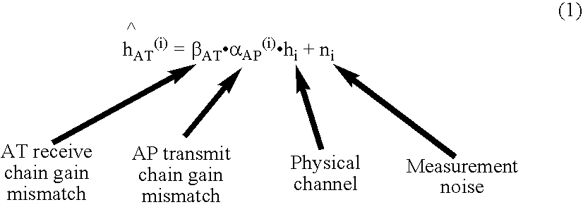
- a forward link channel estimate, ⁇ AT (i) may be estimated at the access terminal for transmissions from the access point's i-th transmit antenna. However, any channel estimate will have components related to the noise of the channel, along with any gain or distortion caused by the access points transmit chain and the access terminals receive chain.
- the forward link channel estimate may then be written as:
- channel estimate is a function of the gain mismatch ⁇ AT of the access terminal receiver chain, the gain mismatch ⁇ AP (i) of the transmitter chain of the access point, h i which is the physical channel between the two antennas being measured, and the noise n i of the channel that is part of the channel estimate.
- Equation 2 Equation 2
- this channel estimate is a function of the gain mismatch ⁇ AT of the access terminal transmit chain, the gain mismatch ⁇ AP (i) of the access point receiver chain, h i which is the physical channel between the two antennas being measured, and the noise ⁇ i of the channel that is part of the channel estimate.
- c i is the overall mismatch ratio between reverse link transmissions and forward link transmission
- ⁇ is the mismatch ratio of the gains between transmit and receive chains of the access terminal
- ⁇ i the mismatch ratio of the receive and transmit chains for the ith antenna at the access point. It should be noted that ⁇ is substantially constant for each antenna pair at the access point.
- Equation 3 is idealized, as the noise estimate is not included therein.
- Equation 4 the entries of vector ⁇ tilde over (c) ⁇ correspond to the estimates for each antenna of the access point with respect to a single access terminal.
- the elements of vector ⁇ may be complex numbers including both the amplitude and phase mismatch for each transmit and receive chains of the access point antenna array as well as common mismatch corresponding to the transmit and receive mismatch of the access terminal transmit and receive chains.
- Equation 4 describes a vector that has entries for one access terminal antennas, it may include entries for multiple access terminals.
- the noise vector n includes effects of channel measurement errors (MSE) and also the effects of channel measurement de-correlation, since the measurements of the gains are performed at different times thus allowing channel variation over time as well as temperature and other variations to effect the measurement.
- MSE channel measurement errors
- An estimated calibration vector ⁇ tilde over (c) ⁇ u corresponding to access terminal u may be determined as shown below in Equation 5.
- ⁇ tilde over (c) ⁇ u ⁇ u ⁇ (5)
- ⁇ u is the gain mismatch corresponding to the access terminal transmit and receive chains
- ⁇ is the mismatch vector corresponding to the access point antenna array transmit and receive chains.
- the vector ⁇ tilde over (c) ⁇ u is determine for all of the antennas of the access point antenna array.
- each calibration vector estimate includes a multiplicative factor, ⁇ u , which is different for different access terminals.
- ⁇ u a multiplicative factor
- each calibration vector estimate, corresponding to a specific access terminal is normalized according to an element of the vector. This may provide minimization in those cases where one or more access terminals have high gain mismatch ⁇ u . This process is depicted below in Equation 6.
- the normalizing element may be any element of the calibration vector, as long as it is the same element for each calibration vector estimate, e.g. the first element.
- the sum of the normalized elements is then divided by the total number of elements U of the vector ⁇ tilde over (c) ⁇ .
- each calibration vector estimate is a rotated and scaled version of the same vector ⁇ and the rotation and scaling are due to the different access terminal mismatches ⁇ u .
- One way to get rid of this scaling and rotation is to first normalize each calibration vector to have a unit norm. Then, a matrix Q whose columns are the normalized calibration vector estimates may be formed from the calibration vectors. A single estimate for the calibration vector is obtained by performing a decomposition of the matrix, e.g. a singular value decomposition on the matrix Q. The eigenvector corresponding to the maximum singular value may be used as the overall calibration vector estimate, e.g. as shown in Equation (7) below.
- a calibration ratio is generally estimated in two steps. First, values corresponding to the elements of calibration vectors are calculated for the antenna array, or those antennas of interest, with respect to the individual access terminals. The calibration vectors are then combined according to one or more different mathematical processes.
- An alternative to calculating multiple calibration vectors is to utilize a joint optimization procedure using multiple access point and access measurement as follows.
- the access terminal and access point may generate their channel estimates for different frequency tones and at different time instants. Further, there may be a timing error of ⁇ k,u between the access point and the u-th access terminal at time k.
- the forward link channel vector estimate g i,k,u measured at the access terminal may be related to the reverse link channel vector estimate h i,k,u measured at the access point.
- Equation 8 One approach, utilizing the calibration vector ⁇ , and the access terminal mismatch ⁇ u is depicted in Equation 8 below.
- Equation 8 A feature of Equation 8 is that access terminal mismatch includes the effect of the timing mismatch between the access point and the access terminal in addition to the gain mismatch due to the access terminal transmit and receive chains.
- MMSE minimum mean squared error
- the calibration ratios may be used to alter the gain, in terms of both or either the phase and amplitude, of the transmitter chain of the access point to match it to the receiver chain or equivalently to alter the gain of the receive chain of the access point to match it to the transmit chain.
- any calibration technique may make the amplitude mismatch worse. This can be easily seen by considering an extreme case where there is no phase mismatch and only amplitude mismatch is present in the gain mismatches. In this case, the beamforming gain with calibration is worse than the beamforming gain without calibration, which means that the amplitude mismatch is now worse.
- a method to improve is to use phase only calibration for beamforming, instead of calibration using both the amplitude and the phase for calculating the calibration weights. In this case the calibrated weights beamforming are calculated for phase only.
- An aspect of this approach for MRC beamforming is depicted in Equation 12 below.
- w MRC diag( ⁇ ⁇ ) ⁇ h*/
- FIG. 2 depicts and describes one embodiment of receiver chain 102 and transmitter chain 104
- FIG. 2 depicts and describes one embodiment of receiver chain 102 and transmitter chain 104
- layouts and structures may be utilized.
- a different number of components may be used in both receiver chain 102 and transmitter chain 104 .
- different devices and structures may also be substituted.
- FIG. 3 illustrates a timing cycle for a calibration from a single access terminal, where a TDD system having a single forward link frame or burst adjacent to a single reverse link frame or burst is utilized.
- one or more pilots transmitted on the reverse link is(are) measured at the access point.
- the time period of the measurement is a function of the decoding time of the access point.
- one or more pilots are transmitted on the forward link to the access terminal.
- the access terminal measures the pilots to estimate the forward link channel.
- some decoding lag exists.
- the decoded forward link estimates need to be transmitted back to the access point in order to generate the calibration ratio. Therefore, it can be seen that there is some minimum amount of time, and therefore maximum access terminal velocity, for which calibration can be maintained without drift being a strong or substantially interfering factor.
- the noise and drift associated may be reduced or at least sampled over a range of times and receive chains.
- FIG. 4 illustrates aspects of logic that facilitates calibrating an antenna array to compensate for gain mismatch.
- the system 300 comprises a calibration component 302 that includes a mismatch estimation component 304 that analyzes models receiver chain output signals and/or comparisons between receiver chain output signals and a calibration calculation and determination 306 utilizes multiple calibration techniques to generate calibration weights, e.g. using vector ⁇ for different types of calibration, and then selects one calibration type based upon the extent of the mismatch that results from using the different types of calibration. In certain aspects, this may be done using phase only estimates to calculate the calibration weights or using phase and amplitude estimates to calculate the calibration weights.
- FIG. 5 illustrates aspects of a system that facilitates calibrating an antenna array to compensate for gain mismatch.
- the system 400 comprises a processor 402 that is operatively coupled to an antenna array 404 .
- Processor 402 can determine calibration weights based upon multiple calibration techniques.
- Processor 402 further comprises a calibration component 406 that selects one calibration type based upon the extent of the mismatch that results from using the different types of calibration.
- System 400 can additionally comprise memory 408 that is operatively coupled to processor 402 and that stores information related to array calibration, ratio generation, different types of calibration techniques, criteria for selecting different types of calibration techniques, and any other suitable information related to calibrating antenna array 404 .
- processor 402 can be a processor dedicated to analyzing and/or generating information received by processor 402 , a processor that controls one or more components of system 400 , and/or a processor that both analyzes and generates information received by processor 402 and controls one or more components of system 400 .
- Memory 408 can additionally store protocols associated with generating signal copies and models/representations, mismatch estimations, etc., such that system 400 can employ stored protocols and/or algorithms to achieve antenna calibration, technique selection, and/or mismatch compensation as described herein.
- the data store (e.g., memories) components described herein can be either volatile memory or nonvolatile memory, or can include both volatile and nonvolatile memory.
- nonvolatile memory can include read only memory (ROM), programmable ROM (PROM), electrically programmable ROM (EPROM), electrically erasable ROM (EEPROM), or flash memory.
- Volatile memory can include random access memory (RAM), which acts as external cache memory.
- RAM is available in many forms such as synchronous RAM (SRAM), dynamic RAM (DRAM), synchronous DRAM (SDRAM), double data rate SDRAM (DDR SDRAM), enhanced SDRAM (ESDRAM), Synchlink DRAM (SLDRAM), and direct Rambus RAM (DRRAM).
- SRAM synchronous RAM
- DRAM dynamic RAM
- SDRAM synchronous DRAM
- DDR SDRAM double data rate SDRAM
- ESDRAM enhanced SDRAM
- SLDRAM Synchlink DRAM
- DRRAM direct Rambus RAM
- the memory 408 of the subject systems and methods is intended to comprise, without being limited to, these and any other suitable types of memory.
- methodologies can relate to antenna array calibration in a TDMA environment, an OFDM environment, an OFDMA environment, a CDMA environment, or any other suitable wireless environment. While, for purposes of simplicity of explanation, the methodologies are shown and described as a series of acts, it is to be understood and appreciated that the methodologies are not limited by the order of acts, as some acts may, in accordance with one or more embodiments, occur in different orders and/or concurrently with other acts from that shown and described herein. For example, those skilled in the art will understand and appreciate that a methodology could alternatively be represented as a series of interrelated states or events, such as in a state diagram. Moreover, not all illustrated acts may be required to implement a methodology in accordance with one or more embodiments.
- memory 408 can store the calibration vectors ⁇ tilde over (c) ⁇ u for each state, i.e. level of amplification, of the AGC.
- the processor 402 may access the calibration vector ⁇ tilde over (c) ⁇ u for the AGC state without performing a calibration.
- the decision as to whether to perform an additional calibration or access a prior calibration vector ⁇ tilde over (c) ⁇ u for a give transmission may be based upon a time period or number of transmissions since the calibration vector ⁇ tilde over (c) ⁇ u for the AGC state was obtained. This may be system parameter or may vary based upon channel conditions, e.g. loading of the channel.
- FIG. 6 illustrates a methodology for calibrating an array of antennas for transmission.
- Channel estimates for the forward link are received from access terminals, block 500 . As discussed above, these channel estimates may be generated from forward link pilots transmitted by the access point. Additionally, channel estimates for the reverse link information, e.g. reverse link channel pilots, are generated by the access point, block 502 .
- calibration ratios for each access terminal and access point antenna may be determined, block 504 .
- the most recent forward link and reverse link channel estimate with respect to each other in time is utilized to form a calibration ratio.
- multiple estimates for a given access terminal may be performed based upon consecutive channel estimate pairs of forward link and reverse link estimates.
- a calibration ratio may be determined for a given access terminal based upon channel estimates of the forward link and reverse link transmissions that may or may not be consecutive in time.
- This combined calibration ratio may include calibration ratios to some or all of the access terminals in a given sector or cell, and have an unequal or equal number of calibration ratios for each access terminal for which one or more calibration ratios are being obtained.
- the combined calibration ratio may be obtained by simply averaging the calibration ratios or utilizing the other approaches discussed with respect to FIG. 2 , e.g. the approaches discussed with respect to Equations 5 or 7.
- Each transmission from each transmission chain of the access point is then weighted with weights based upon the combined calibration ratio for that transmit chain.
- a combined or joint set of calibrations weights may be utilized for one or more transmit chains of the access point.
- the calibration weights are utilized for a particular AGC state and not for other AGC states. As such, block 508 , would then only apply to the AGC state during block 500 .
- FIG. 7 illustrates another methodology for calibrating an array of antennas for transmission.
- Channel estimates for the forward link are received from access terminals, block 600 . As discussed above, these channel estimates may be generated from forward link pilots transmitted by the access point. Additionally, channel estimates for the reverse link information, e.g. reverse link channel pilots, are generated by the access point, block 602 .
- a calibration ratio that utilizes multiple channel estimates for multiple access terminals block 604 .
- the most recent forward link and reverse link channel estimate with respect to each other in time is utilized.
- multiple estimates for a given access terminal may be performed based upon consecutive channel estimate pairs of forward link and reverse link estimates.
- the channel estimates may be determined for a given access terminal based upon channel estimates of the forward link and reverse link transmissions that may or may not be consecutive in time.
- the joint calibration ratio may be obtained by utilizing a joint optimization process as discussed with respect to FIG. 2 , e.g. to Equation 8.
- Each transmission from each transmission chain of the access point is then weighted with weights based upon the joint calibration ratio for that transmit chain.
- a combined or joint set of calibrations weights may be utilized for one or more transmit chains of the access point.
- the calibration weights are utilized for a particular AGC state and not for other AGC states. As such, block 608 , would then only apply to the AGC state during block 600 .
- FIG. 8 illustrates an exemplary wireless communication system 1300 .
- the wireless communication system 1300 depicts one base station and one terminal for sake of brevity.
- the system can include more than one base station and/or more than one terminal, wherein additional base stations and/or terminals can be substantially similar or different for the exemplary base station and terminal described below.
- the base station and/or the terminal can employ the systems ( FIGS. 1-5 ) and/or methods ( FIG. 6-7 or 10 ) described herein to facilitate wireless communication there between.
- a transmit (TX) data processor 1310 receives, formats, codes, interleaves, and modulates (or symbol maps) traffic data and provides modulation symbols (“data symbols”).
- a symbol modulator 1315 receives and processes the data symbols and pilot symbols and provides a stream of symbols.
- a symbol modulator 1315 multiplexes data and pilot symbols on the proper subcarriers, provides a signal value of zero for each unused subcarrier, and obtains a set of N transmit symbols for the N subcarriers for each symbol period.
- Each transmit symbol may be a data symbol, a pilot symbol, or a signal value of zero.
- the pilot symbols may be sent continuously in each symbol period.
- pilot symbols may be time division multiplexed (TDM), frequency division multiplexed (FDM), orthogonal frequency division multiplexed (OFDM), code division multiplexed (CDM), etc.
- Symbol modulator 1315 can transform each set of N transmit symbols to the time domain using an N-point IFFT to obtain a “transformed” symbol that contains N time-domain chips.
- Symbol modulator 1315 typically repeats a portion of each transformed symbol to obtain a corresponding symbol. The repeated portion is known as a cyclic prefix and is used to combat delay spread in the wireless channel.
- a transmitter unit (TMTR) 1320 receives and converts the stream of symbols into one or more analog signals and further conditions (e.g., amplifies, filters, and frequency upconverts) the analog signals to generate a forward link signal suitable for transmission over the wireless channel.
- the forward link signal is then transmitted through an antenna 1325 to the terminals.
- an antenna 1335 receives the forward link signal and provides a received signal to a receiver unit (RCVR) 1340 .
- Receiver unit 1340 conditions (e.g., filters, amplifies, and frequency downconverts) the received signal and digitizes the conditioned signal to obtain samples.
- a symbol demodulator 1345 removes the cyclic prefix appended to each symbol, transforms each received transformed symbol to the frequency domain using an N-point FFT, obtains N received symbols for the N subcarriers for each symbol period, and provides received pilot symbols to a processor 1350 for channel estimation.
- Symbol demodulator 1345 further receives a frequency response estimate for the forward link from processor 1350 , performs data demodulation on the received data symbols to obtain data symbol estimates (which are estimates of the transmitted data symbols), and provides the data symbol estimates to an RX data processor 1355 , which demodulates (e.g., symbol demaps), deinterleaves, and decodes the data symbol estimates to recover the transmitted traffic data.
- the processing by symbol demodulator 1345 and RX data processor 1355 is complementary to the processing by symbol modulator 1315 and TX data processor 1310 , respectively, at access point 1305 .
- a TX data processor 1360 processes traffic data and provides data symbols.
- a symbol modulator 1365 receives and multiplexes the data symbols with pilot symbols, performs modulation, and provides a stream of symbols.
- the pilot symbols may be transmitted on subcarriers that have been assigned to terminal 1330 for pilot transmission, where the number of pilot subcarriers for the reverse link may be the same or different from the number of pilot subcarriers for the forward link.
- a transmitter unit 1370 then receives and processes the stream of symbols to generate a reverse link signal, which is transmitted by the antenna 1335 to the access point 1305 .
- the reverse link signal from terminal 1330 is received by the antenna 1325 and processed by a receiver unit 1375 to obtain samples.
- a symbol demodulator 1380 then processes the samples and provides received pilot symbols and data symbol estimates for the reverse link.
- An RX data processor 1385 processes the data symbol estimates to recover the traffic data transmitted by terminal 1330 .
- a processor 1390 performs channel estimation for each active terminal transmitting on the reverse link.
- the processor 1390 may also be configured to utilize multiple calibration techniques to calculate the weights for calibration and to select the weights calculated according to one the techniques as discussed with respect to FIGS. 2 and 10 .
- Processors 1390 and 1350 direct (e.g., control coordinate, manage, etc.) operation at access point 1305 and terminal 1330 , respectively. Respective processors 1390 and 1350 can be associated with memory units (not shown) that store program codes and data. Processors 1390 and 1350 can also perform computations to derive frequency and impulse response estimates for the reverse link and forward link, respectively.
- an access point 1400 can comprise a main unit (MU) 1450 and a radio unit (RU) 1475 .
- MU 1450 includes the digital baseband components of an access point 1400 .
- MU 1450 can include a baseband component 1405 and a digital intermediate frequency (IF) processing unit 1410 .
- Digital IF processing unit 1410 digitally processes radio channel data at an intermediate frequency by performing such functions as filtering, channelizing, modulation, and so forth.
- RU 1475 includes the analog radio parts of the access point 1400 .
- a radio unit is the analog radio parts of an access point or other type of transceiver station with direct or indirect connection to a mobile switching center or corresponding device.
- a radio unit typically serves a particular sector in a communication system.
- RU 1475 can include one or more receivers 1430 connected to one or more antennas 1435 a - t for receiving radio communications from mobile subscriber units.
- one or more power amplifiers 1482 a - t are coupled to one or more antennas 1435 a - t .
- Connected to receiver 1430 is an analog-to-digital (A/D) converter 1425 .
- A/D converter 1425 converts the analog radio communications received by receiver 1430 into digital input for transmission to baseband component 1405 via digital IF processing unit 1410 .
- RU 1475 can also include one or more transmitters 1420 connected to either the same or different antenna 1435 for transmitting radio communications to access terminals.
- D/A converter 1415 Connected to transmitter 1420 is a digital-to-analog (D/A) converter 1415 .
- D/A converter 1415 converts the digital communications received from baseband component 1405 via digital IF processing unit 1410 into analog output for transmission to the mobile subscriber units.
- a multiplexer 1484 for multiplexing of multiple-channel signals and multiplexing of a variety of signals including a voice signal and a data signal.
- a central processor 1480 is coupled to main unit 1450 and RU 1475 for controlling various processing which includes the processing of voice or data signal.
- FIG. 10 illustrates aspects of a methodology for determining a type of calibration to apply.
- Calibration weights are determined for approaches are performed using phase only mismatch information, block 1500 , and using phase and amplitude mismatch information, block 1502 .
- Phase only information may include only the phase of the calibration vectors, channel estimates, or the like to calculate the calibration weights.
- Phase and amplitude information may include the phase and amplitude information of the calibration vectors, channel estimates, or the like to calculate the calibration weights.
- the calibration weights may be calculated based upon information from multiple access terminals as described with respect to FIGS. 6 and 7 . Alternatively, they may be from information for a single access terminal.
- ⁇ ⁇ represents the amplitude difference between the uncalibrated and calibrated weights for the transmit chain of the antenna of the access point and ⁇ ⁇ represents the amplitude difference between the uncalibrated and calibrated weights for the receive chain of the antenna of the access point. Then a determination may be made whether these exceed some threshold for their relationship. For example, whether the minimum is greater than the maximum by some predetermined or system calculated factor, e.g. 3. In other cases, a determination of whether one, or both, of ⁇ ⁇ and ⁇ ⁇ exceeds some predetermined threshold. In other cases, different measurements of the calibration mismatch, thresholds, or relationships may be utilized. The selected weights are then applied, block 1506 .
- multiple terminals may transmit concurrently on the reverse link.
- the pilot subcarriers may be shared among different terminals.
- the channel estimation techniques may be used in cases where the pilot subcarriers for each terminal span the entire operating band (possibly except for the band edges). Such a pilot subcarrier structure would be desirable to obtain frequency diversity for each terminal.
- the techniques described herein may be implemented by various means. For example, these techniques may be implemented in hardware, software, or a combination thereof.
- the processing units used for channel estimation may be implemented within one or more application specific integrated circuits (ASICs), digital signal processors (DSPs), digital signal processing devices (DSPDs), programmable logic devices (PLDs), field programmable gate arrays (FPGAs), processors, controllers, micro-controllers, microprocessors, other electronic units designed to perform the functions described herein, or a combination thereof.
- ASICs application specific integrated circuits
- DSPs digital signal processors
- DSPDs digital signal processing devices
- PLDs programmable logic devices
- FPGAs field programmable gate arrays
- processors controllers, micro-controllers, microprocessors, other electronic units designed to perform the functions described herein, or a combination thereof.
- implementation can be through modules (e.g., procedures, functions, and so on) that perform the functions described herein.
- the software codes may be stored in memory unit and executed by the processors 1390 and 1350 .
Abstract
Description
In

In
In Equation 3, ci is the overall mismatch ratio between reverse link transmissions and forward link transmission, γ is the mismatch ratio of the gains between transmit and receive chains of the access terminal, and ηi is the mismatch ratio of the receive and transmit chains for the ith antenna at the access point. It should be noted that γ is substantially constant for each antenna pair at the access point. Also, in some regards Equation 3 is idealized, as the noise estimate is not included therein.
In Equation 4, the entries of vector {tilde over (c)} correspond to the estimates for each antenna of the access point with respect to a single access terminal. It should be noted that the elements of vector ĉ may be complex numbers including both the amplitude and phase mismatch for each transmit and receive chains of the access point antenna array as well as common mismatch corresponding to the transmit and receive mismatch of the access terminal transmit and receive chains. It should be noted that while Equation 4, describes a vector that has entries for one access terminal antennas, it may include entries for multiple access terminals.
{tilde over (c)} u=γu·η (5)
where γu is the gain mismatch corresponding to the access terminal transmit and receive chains and η is the mismatch vector corresponding to the access point antenna array transmit and receive chains. The vector {tilde over (c)}u is determine for all of the antennas of the access point antenna array.
It should be noted that, in certain aspects, the normalizing element may be any element of the calibration vector, as long as it is the same element for each calibration vector estimate, e.g. the first element. The sum of the normalized elements is then divided by the total number of elements U of the vector {tilde over (c)}.
In
Solutions for η and γi,k,u may be given by Equation 10 below.
where, for a vector x, the orthogonal projection operator Πx ⊥ may be defined as
w MRC=diag(ηφ)·h*/|h|,|h|=√{square root over (h*·h)} for MRC (12)
where diag(η100)=diag(@η).
σmax 2=max(σα 2,σβ 2) and σmin 2=min(σα 2,σβ 2) (13)
Claims (20)
Priority Applications (10)
| Application Number | Priority Date | Filing Date | Title |
|---|---|---|---|
| US11/405,832 US9118111B2 (en) | 2005-11-02 | 2006-04-17 | Antenna array calibration for wireless communication systems |
| CN200680049849.1A CN101351978B (en) | 2005-11-02 | 2006-11-02 | Antenna array calibration for wireless communication systems |
| JP2008539158A JP5570724B2 (en) | 2005-11-02 | 2006-11-02 | Antenna array calibration for wireless communication systems |
| KR1020087013362A KR100989540B1 (en) | 2005-11-02 | 2006-11-02 | Antenna array calibration for wireless communication systems |
| PCT/US2006/060495 WO2007056672A2 (en) | 2005-11-02 | 2006-11-02 | Antenna array calibration for wireless communication systems |
| CA2628478A CA2628478C (en) | 2005-11-02 | 2006-11-02 | Antenna array calibration for wireless communication systems |
| EP06846215.9A EP1946407B1 (en) | 2005-11-02 | 2006-11-02 | Antenna array calibration for wireless communication systems |
| BRPI0618183A BRPI0618183B1 (en) | 2005-11-02 | 2006-11-02 | antenna array calibration for wireless communication systems |
| TW095140637A TWI356600B (en) | 2005-11-02 | 2006-11-02 | Antenna array calibration for wireless communicati |
| JP2012040100A JP5701791B2 (en) | 2005-11-02 | 2012-02-27 | Antenna array calibration for wireless communication systems |
Applications Claiming Priority (2)
| Application Number | Priority Date | Filing Date | Title |
|---|---|---|---|
| US73302205P | 2005-11-02 | 2005-11-02 | |
| US11/405,832 US9118111B2 (en) | 2005-11-02 | 2006-04-17 | Antenna array calibration for wireless communication systems |
Publications (2)
| Publication Number | Publication Date |
|---|---|
| US20070099670A1 US20070099670A1 (en) | 2007-05-03 |
| US9118111B2 true US9118111B2 (en) | 2015-08-25 |
Family
ID=40269752
Family Applications (1)
| Application Number | Title | Priority Date | Filing Date |
|---|---|---|---|
| US11/405,832 Expired - Fee Related US9118111B2 (en) | 2005-11-02 | 2006-04-17 | Antenna array calibration for wireless communication systems |
Country Status (2)
| Country | Link |
|---|---|
| US (1) | US9118111B2 (en) |
| CN (1) | CN101351978B (en) |
Cited By (3)
| Publication number | Priority date | Publication date | Assignee | Title |
|---|---|---|---|---|
| US20170116442A1 (en) * | 2015-07-08 | 2017-04-27 | Sensanna Incorporated | Interference immune radio |
| US11362742B2 (en) * | 2019-05-14 | 2022-06-14 | Space Exploration Technologies Corp. | Over-the-air calibration of antenna system |
| US11784408B2 (en) | 2020-07-05 | 2023-10-10 | Space Exploration Technologies Corp. | System and method for over-the-air antenna calibration |
Families Citing this family (18)
| Publication number | Priority date | Publication date | Assignee | Title |
|---|---|---|---|---|
| KR100633047B1 (en) * | 2004-12-02 | 2006-10-11 | 삼성전자주식회사 | Smart Antenna Communication System Employing Apparatus And Method For Signal Calibration |
| US20060240784A1 (en) * | 2005-04-22 | 2006-10-26 | Qualcomm Incorporated | Antenna array calibration for wireless communication systems |
| US8498669B2 (en) * | 2005-06-16 | 2013-07-30 | Qualcomm Incorporated | Antenna array calibration for wireless communication systems |
| US8280430B2 (en) * | 2005-11-02 | 2012-10-02 | Qualcomm Incorporated | Antenna array calibration for multi-input multi-output wireless communication systems |
| CN101558580B (en) * | 2006-12-15 | 2013-06-05 | 富士通株式会社 | Mobile station and antenna verification control method at mobile station |
| WO2008095288A1 (en) * | 2007-02-05 | 2008-08-14 | Research In Motion Limited | Apparatus, and associated method, for operating upon received data at a receiving station capable of diversity operation |
| US8144634B2 (en) * | 2007-02-21 | 2012-03-27 | Telefonaktiebolaget Lm Ericsson (Publ) | Reducing automatic gain control process in time division duplex communication mode |
| AU2011235950B2 (en) * | 2007-10-03 | 2014-04-17 | Qualcomm Incorporated | Calibration and beamforming in a wireless communication system |
| US20090093222A1 (en) * | 2007-10-03 | 2009-04-09 | Qualcomm Incorporated | Calibration and beamforming in a wireless communication system |
| US8290503B2 (en) | 2009-02-01 | 2012-10-16 | Qualcomm Incorporated | Multichannel dynamic frequency selection |
| CN105162502B (en) * | 2009-07-21 | 2018-11-16 | 英特尔公司 | The mobile device for sending diversity of reverse link, method and system |
| CN102082745B (en) * | 2010-04-19 | 2013-10-16 | 电信科学技术研究院 | Method and equipment for reporting antenna calibration information and determining antenna calibration factor |
| US8971948B1 (en) * | 2010-11-19 | 2015-03-03 | Qualcomm Incorporated | Systems and methods for compensating antenna gain imbalance |
| CN102170320A (en) * | 2011-04-15 | 2011-08-31 | 北京邮电大学 | Method and equipment for calibrating reference antenna between two base stations in CoMP (Coordinated Multi-Point) system and base station |
| US8970427B2 (en) | 2011-05-18 | 2015-03-03 | Mediatek Singapore Pte. Ltd. | Phase-arrayed device and method for calibrating the phase-arrayed device |
| WO2019214984A1 (en) * | 2018-05-09 | 2019-11-14 | Sony Corporation | Calibrating an array antenna |
| CN109309533B (en) * | 2018-09-04 | 2021-05-18 | 华为技术有限公司 | Calibration method and device |
| CN114374446B (en) * | 2021-12-23 | 2023-10-24 | 成都玖锦科技有限公司 | Amplitude-phase characteristic measurement method based on pulse signals |
Citations (76)
| Publication number | Priority date | Publication date | Assignee | Title |
|---|---|---|---|---|
| JPH01213038A (en) | 1988-02-22 | 1989-08-25 | Mitsubishi Electric Corp | Transmitting and receiving module inspection confirming device |
| US5008900A (en) | 1989-08-14 | 1991-04-16 | International Mobile Machines Corporation | Subscriber unit for wireless digital subscriber communication system |
| EP0642191A1 (en) | 1993-09-03 | 1995-03-08 | Matra Marconi Space Uk Limited | A digitally controlled beam former for a spacecraft |
| EP0654915A2 (en) | 1993-11-19 | 1995-05-24 | AT&T Corp. | Multipathreception using matrix calculation and adaptive beamforming |
| JPH1127031A (en) | 1997-07-04 | 1999-01-29 | Jisedai Eisei Tsushin Hoso Syst Kenkyusho:Kk | Setting method for exciting amplitude and phase of array antenna |
| WO1999014870A2 (en) | 1997-09-15 | 1999-03-25 | Adaptive Telecom, Inc. | Practical space-time radio method for cdma communication capacity enhancement |
| WO1999057820A1 (en) | 1998-05-01 | 1999-11-11 | Arraycomm, Inc. | Method and apparatus for determining spatial signatures for calibrating a communication station having an antenna array |
| US6037898A (en) | 1997-10-10 | 2000-03-14 | Arraycomm, Inc. | Method and apparatus for calibrating radio frequency base stations using antenna arrays |
| GB2346013A (en) | 1998-11-27 | 2000-07-26 | Radio Design Innovation Tj Ab | Calibration method for a phased array |
| JP2000216618A (en) | 1998-11-19 | 2000-08-04 | Nippon Telegr & Teleph Corp <Ntt> | Adaptive array antenna system |
| US6188896B1 (en) | 1999-02-22 | 2001-02-13 | Trw Inc. | Cellular satellite communication system and method for controlling antenna gain pattern therein |
| WO2001019101A1 (en) | 1999-09-10 | 2001-03-15 | Utstarcom. Inc. | Method and apparatus for calibrating a smart antenna array |
| EP1104122A1 (en) | 1998-08-05 | 2001-05-30 | Sanyo Electric Co., Ltd. | Radio device and method of calibration thereof |
| US20010005685A1 (en) | 1999-12-15 | 2001-06-28 | Kentaro Nishimori | Adaptive array antenna transceiver apparatus |
| JP2001177458A (en) | 1999-12-20 | 2001-06-29 | Nippon Telegr & Teleph Corp <Ntt> | Adaptive array antenna transmitter-receiver and its calibration method |
| US20010011961A1 (en) | 2000-02-01 | 2001-08-09 | Leonard Rexberg | Array antenna calibration |
| KR20010076252A (en) | 2000-01-13 | 2001-08-11 | 루센트 테크놀러지스 인크 | Space-time processing for multiple-input, multiple-output, wireless systems |
| US20010020919A1 (en) | 2000-03-07 | 2001-09-13 | Yasushi Maruta | Array antenna receiving apparatus |
| EP1133836A1 (en) | 1998-11-24 | 2001-09-19 | ArrayComm, Inc. | Method and apparatus for calibrating a wireless communications station having an antenna array |
| KR20010110464A (en) | 1999-03-30 | 2001-12-13 | 다카노 야스아키 | Radio device and method of calibration of antenna directivity |
| WO2002011237A1 (en) | 2000-07-31 | 2002-02-07 | Nokia Corporation | Calibration apparatus and method for use with an antenna array |
| KR20020022109A (en) | 1999-09-01 | 2002-03-23 | 밀러 럿셀 비 | Method and apparatus for beamforming in a wireless communication system |
| KR20020026605A (en) | 2000-06-29 | 2002-04-10 | 마츠시타 덴끼 산교 가부시키가이샤 | Radio base station unit and radio communication method |
| JP2002141730A (en) | 2000-11-01 | 2002-05-17 | Toshiba Tec Corp | Directional antenna system and calibration method for this system |
| US20020103013A1 (en) * | 2001-01-31 | 2002-08-01 | Watson Stephen J. | Signal detection using a phased array antenna |
| KR200289094Y1 (en) | 2002-04-24 | 2002-09-13 | 솔루텍 주식회사 | Auto attendant apparatus |
| WO2002078209A2 (en) | 2001-03-27 | 2002-10-03 | Nokia Corporation | Method for calibrating a smart-antenna array, radio transceiver unit and calibrating system |
| US20030040880A1 (en) | 2001-08-15 | 2003-02-27 | Raytheon Company | Combining signal images in accordance with signal-to-noise ratios |
| US20030058166A1 (en) | 2001-09-17 | 2003-03-27 | Nec Corporation | Apparatus and method for calibrating array antenna |
| US20030064752A1 (en) | 2001-09-28 | 2003-04-03 | Tomoko Adachi | Base station apparatus and terminal apparatus |
| US20030064762A1 (en) | 2001-10-01 | 2003-04-03 | Masayoshi Tanabe | Electronic device and mobile radio terminal apparatus |
| US6600445B2 (en) | 1999-08-10 | 2003-07-29 | China Academy Of Telecommunications Technology | Method and device for calibrating smart antenna array |
| JP2003264492A (en) | 2002-03-08 | 2003-09-19 | Sony Corp | Radio communication equipment, and characteristic adjusting method for array antenna |
| JP2003309513A (en) | 2002-04-16 | 2003-10-31 | Matsushita Electric Ind Co Ltd | Adaptive array antenna reception apparatus and antenna array calibration method |
| US6661284B1 (en) | 2002-05-15 | 2003-12-09 | Motorola, Inc. | Method and apparatus for error compensation in a hybrid matrix amplification system |
| US20030227408A1 (en) | 2002-01-23 | 2003-12-11 | Sony Corporation | Antenna apparatus |
| US6701264B2 (en) | 2001-07-31 | 2004-03-02 | Trw Northrop | Method of and apparatus for calibrating receive path gain |
| US20040048580A1 (en) * | 2001-06-21 | 2004-03-11 | Tim Lunn | Base transceiver station |
| US20040048584A1 (en) | 2002-09-10 | 2004-03-11 | Chandra Vaidyanathan | Techniques for correcting for phase and amplitude offsets in a MIMO radio device |
| WO2004038952A2 (en) | 2002-10-25 | 2004-05-06 | Qualcomm, Incorporated | Channel estimation and spatial processing for tdd mimo systems |
| WO2004039022A2 (en) | 2002-10-25 | 2004-05-06 | Qualcomm, Incorporated | Correction for differences between downlink and uplink channel responses |
| WO2004039011A2 (en) | 2002-10-25 | 2004-05-06 | Qualcomm Incorporated | Mimo wlan system |
| US20040105386A1 (en) | 2002-12-02 | 2004-06-03 | Jussi Sipola | Method for scheduling of plural packet data flows |
| US20040110538A1 (en) * | 2001-03-21 | 2004-06-10 | Yoshiharu Doi | Wireless base system, and directivity control method |
| US20040142729A1 (en) | 2002-11-14 | 2004-07-22 | Yasuaki Yuda | Radio communication apparatus |
| JP2004304586A (en) | 2003-03-31 | 2004-10-28 | Japan Radio Co Ltd | Array antenna communication equipment |
| US20040217920A1 (en) | 2000-03-10 | 2004-11-04 | Pioneer Corporation | Apparatus for displaying a stereoscopic two-dimensional image and method therefor |
| JP2004343468A (en) | 2003-05-16 | 2004-12-02 | Japan Radio Co Ltd | Array antenna communication apparatus |
| US20040266483A1 (en) | 2001-10-05 | 2004-12-30 | Seung-Won Choi | Calibration apparatus for smart antenna and method thereof |
| US20050070333A1 (en) | 2003-09-29 | 2005-03-31 | Sanyo Electric Co., Ltd. | Calibration method and radio apparatus |
| US6876870B2 (en) * | 2000-12-21 | 2005-04-05 | Matsushita Electric Industrial Co., Ltd. | Wireless base station apparatus and wireless communication method |
| US20050095996A1 (en) | 2003-11-05 | 2005-05-05 | Sony Corporation | Wireless communications system, wireless communications method, and wireless communications apparatus |
| US6904290B1 (en) | 1999-09-30 | 2005-06-07 | Telefonaktiebolaget L M Ericsson (Publ) | Method and apparatus for transmit power control |
| US20050130663A1 (en) | 2003-11-28 | 2005-06-16 | Ki-Seob Hong | Apparatus and method for controlling a forward data rate in a mobile communication system |
| US20050141630A1 (en) * | 2003-07-09 | 2005-06-30 | Severine Catreux | Weight generation method for multi-antenna communication systems utilizing RF-based and baseband signal weighting and combining based upon minimum bit error rate |
| US20050164664A1 (en) | 2000-07-21 | 2005-07-28 | Difonzo Daniel F. | Dynamically reconfigurable wireless networks (DRWiN) and methods for operating such networks |
| US20050162305A1 (en) | 2003-11-19 | 2005-07-28 | Roke Manor Research Ltd. | Method of calibrating an adaptive antenna array of a satellite navigation system |
| WO2005081483A1 (en) | 2004-02-19 | 2005-09-01 | Qualcomm Incorporated | Calibration of downlink and uplink channel responses in a wireless mimo communication system |
| US20060019712A1 (en) * | 2001-11-14 | 2006-01-26 | Seung-Won Choi | Calibration apparatus for smart antenna and method thereof |
| JP2006512807A (en) | 2002-12-25 | 2006-04-13 | 大唐移動通信設備有限公司 | Method for calibrating a smart antenna array system in real-time |
| KR100584625B1 (en) | 2001-05-17 | 2006-05-30 | 삼성전자주식회사 | Mobile communication apparatus and method including antenna array |
| US7079514B2 (en) | 2001-05-17 | 2006-07-18 | Samsung Electronics Co., Ltd. | Mobile communication apparatus with antenna array and mobile communication method thereof |
| US20060232470A1 (en) | 2005-04-13 | 2006-10-19 | Brian Mallick | System for the relative navigation of aircraft and spacecraft using a phased array antenna |
| US20060240784A1 (en) | 2005-04-22 | 2006-10-26 | Qualcomm Incorporated | Antenna array calibration for wireless communication systems |
| WO2006116453A1 (en) | 2005-04-22 | 2006-11-02 | Qualcomm Incorporated | Antenna array calibration for wireless communication systems |
| US20060284725A1 (en) | 2005-06-16 | 2006-12-21 | Naguib Ayman F | Antenna array calibration for wireless communication systems |
| US20060286974A1 (en) | 2005-06-16 | 2006-12-21 | Qualcomm Incorporated | Adaptive sectorization in cellular systems |
| US20060293087A1 (en) * | 2005-06-22 | 2006-12-28 | Fujitsu Limited | Wireless communication apparatus and phase-variation correction method |
| US7205936B2 (en) | 2003-12-27 | 2007-04-17 | Electronics And Telecommunications Research Institute | Transmitting and receiving apparatus and method in adaptive array antenna system capable of real-time error calibration |
| US20070099570A1 (en) * | 2005-10-31 | 2007-05-03 | Silicon Laboratories, Inc. | Receiver with multi-tone wideband I/Q mismatch calibration and method therefor |
| US20070099573A1 (en) | 2005-11-02 | 2007-05-03 | Qualcomm Incorporated | Antenna array calibration for multi-input multi-output wireless communication systems |
| US20070224942A1 (en) * | 2004-08-06 | 2007-09-27 | Katsuyuki Kuramoto | Radio-Frequency Receiver Device |
| US20070225042A1 (en) * | 2004-06-30 | 2007-09-27 | Kyocera Corporation | Communication Device, Calibration Method, and Program |
| US7277679B1 (en) * | 2001-09-28 | 2007-10-02 | Arraycomm, Llc | Method and apparatus to provide multiple-mode spatial processing to a terminal unit |
| US7313174B2 (en) | 2001-02-08 | 2007-12-25 | Wavecom | Method for extracting a variable reference pattern |
| US7392016B2 (en) | 2002-02-28 | 2008-06-24 | Intel Corporation | Data transmission rate control |
Family Cites Families (1)
| Publication number | Priority date | Publication date | Assignee | Title |
|---|---|---|---|---|
| KR100449578B1 (en) * | 2001-09-14 | 2004-09-21 | 한국전자통신연구원 | Iterative decoding method for block turbo codes more than 3-dimensions |
-
2006
- 2006-04-17 US US11/405,832 patent/US9118111B2/en not_active Expired - Fee Related
- 2006-11-02 CN CN200680049849.1A patent/CN101351978B/en active Active
Patent Citations (98)
| Publication number | Priority date | Publication date | Assignee | Title |
|---|---|---|---|---|
| JPH01213038A (en) | 1988-02-22 | 1989-08-25 | Mitsubishi Electric Corp | Transmitting and receiving module inspection confirming device |
| US5008900A (en) | 1989-08-14 | 1991-04-16 | International Mobile Machines Corporation | Subscriber unit for wireless digital subscriber communication system |
| EP0642191A1 (en) | 1993-09-03 | 1995-03-08 | Matra Marconi Space Uk Limited | A digitally controlled beam former for a spacecraft |
| EP0654915A2 (en) | 1993-11-19 | 1995-05-24 | AT&T Corp. | Multipathreception using matrix calculation and adaptive beamforming |
| JPH1127031A (en) | 1997-07-04 | 1999-01-29 | Jisedai Eisei Tsushin Hoso Syst Kenkyusho:Kk | Setting method for exciting amplitude and phase of array antenna |
| WO1999014870A2 (en) | 1997-09-15 | 1999-03-25 | Adaptive Telecom, Inc. | Practical space-time radio method for cdma communication capacity enhancement |
| WO2000031892A1 (en) | 1997-10-10 | 2000-06-02 | Arraycomm, Inc. | Method and apparatus for calibrating a wireless communications station having an antenna array |
| US6037898A (en) | 1997-10-10 | 2000-03-14 | Arraycomm, Inc. | Method and apparatus for calibrating radio frequency base stations using antenna arrays |
| WO1999057820A1 (en) | 1998-05-01 | 1999-11-11 | Arraycomm, Inc. | Method and apparatus for determining spatial signatures for calibrating a communication station having an antenna array |
| US6615024B1 (en) | 1998-05-01 | 2003-09-02 | Arraycomm, Inc. | Method and apparatus for determining signatures for calibrating a communication station having an antenna array |
| CN1507168A (en) | 1998-05-01 | 2004-06-23 | ���˹���Ѷ��� | Method and equipment for determining space character in order to calibrate communication station with antenna array |
| EP1104122A1 (en) | 1998-08-05 | 2001-05-30 | Sanyo Electric Co., Ltd. | Radio device and method of calibration thereof |
| JP3332911B2 (en) | 1998-08-05 | 2002-10-07 | 三洋電機株式会社 | Wireless device and calibration method thereof |
| JP2000216618A (en) | 1998-11-19 | 2000-08-04 | Nippon Telegr & Teleph Corp <Ntt> | Adaptive array antenna system |
| JP2002530998A (en) | 1998-11-24 | 2002-09-17 | アレイコム・インコーポレーテッド | Method and apparatus for calibrating a wireless communication station having an array antenna |
| EP1133836A1 (en) | 1998-11-24 | 2001-09-19 | ArrayComm, Inc. | Method and apparatus for calibrating a wireless communications station having an antenna array |
| GB2346013A (en) | 1998-11-27 | 2000-07-26 | Radio Design Innovation Tj Ab | Calibration method for a phased array |
| US6188896B1 (en) | 1999-02-22 | 2001-02-13 | Trw Inc. | Cellular satellite communication system and method for controlling antenna gain pattern therein |
| US7035592B1 (en) | 1999-03-30 | 2006-04-25 | Sanyo Electric Co., Ltd. | Radio device and method of calibration of antenna directivity |
| KR20010110464A (en) | 1999-03-30 | 2001-12-13 | 다카노 야스아키 | Radio device and method of calibration of antenna directivity |
| US6600445B2 (en) | 1999-08-10 | 2003-07-29 | China Academy Of Telecommunications Technology | Method and device for calibrating smart antenna array |
| KR20020022109A (en) | 1999-09-01 | 2002-03-23 | 밀러 럿셀 비 | Method and apparatus for beamforming in a wireless communication system |
| WO2001019101A1 (en) | 1999-09-10 | 2001-03-15 | Utstarcom. Inc. | Method and apparatus for calibrating a smart antenna array |
| US6904290B1 (en) | 1999-09-30 | 2005-06-07 | Telefonaktiebolaget L M Ericsson (Publ) | Method and apparatus for transmit power control |
| US20010005685A1 (en) | 1999-12-15 | 2001-06-28 | Kentaro Nishimori | Adaptive array antenna transceiver apparatus |
| US6690952B2 (en) | 1999-12-15 | 2004-02-10 | Nippon Telegraph & Telephone Corporation | Adaptive array antenna transceiver apparatus |
| JP2001177458A (en) | 1999-12-20 | 2001-06-29 | Nippon Telegr & Teleph Corp <Ntt> | Adaptive array antenna transmitter-receiver and its calibration method |
| US6888809B1 (en) | 2000-01-13 | 2005-05-03 | Lucent Technologies Inc. | Space-time processing for multiple-input, multiple-output, wireless systems |
| KR20010076252A (en) | 2000-01-13 | 2001-08-11 | 루센트 테크놀러지스 인크 | Space-time processing for multiple-input, multiple-output, wireless systems |
| US6462704B2 (en) | 2000-02-01 | 2002-10-08 | Telefonaktiebolaget Lm Ericsson (Publ) | Array antenna calibration |
| US20010011961A1 (en) | 2000-02-01 | 2001-08-09 | Leonard Rexberg | Array antenna calibration |
| US20010020919A1 (en) | 2000-03-07 | 2001-09-13 | Yasushi Maruta | Array antenna receiving apparatus |
| US6448939B2 (en) | 2000-03-07 | 2002-09-10 | Nec Corporation | Array antenna receiving apparatus |
| US20040217920A1 (en) | 2000-03-10 | 2004-11-04 | Pioneer Corporation | Apparatus for displaying a stereoscopic two-dimensional image and method therefor |
| US7133698B2 (en) * | 2000-06-29 | 2006-11-07 | Matsushita Electric Industrial Co., Ltd. | Radio base station apparatus and radio communication method |
| KR20020026605A (en) | 2000-06-29 | 2002-04-10 | 마츠시타 덴끼 산교 가부시키가이샤 | Radio base station unit and radio communication method |
| US20050164664A1 (en) | 2000-07-21 | 2005-07-28 | Difonzo Daniel F. | Dynamically reconfigurable wireless networks (DRWiN) and methods for operating such networks |
| WO2002011237A1 (en) | 2000-07-31 | 2002-02-07 | Nokia Corporation | Calibration apparatus and method for use with an antenna array |
| JP2002141730A (en) | 2000-11-01 | 2002-05-17 | Toshiba Tec Corp | Directional antenna system and calibration method for this system |
| US6876870B2 (en) * | 2000-12-21 | 2005-04-05 | Matsushita Electric Industrial Co., Ltd. | Wireless base station apparatus and wireless communication method |
| US20020103013A1 (en) * | 2001-01-31 | 2002-08-01 | Watson Stephen J. | Signal detection using a phased array antenna |
| US7313174B2 (en) | 2001-02-08 | 2007-12-25 | Wavecom | Method for extracting a variable reference pattern |
| US20040110538A1 (en) * | 2001-03-21 | 2004-06-10 | Yoshiharu Doi | Wireless base system, and directivity control method |
| WO2002078209A2 (en) | 2001-03-27 | 2002-10-03 | Nokia Corporation | Method for calibrating a smart-antenna array, radio transceiver unit and calibrating system |
| US6496140B1 (en) | 2001-03-27 | 2002-12-17 | Nokia Networks Oy | Method for calibrating a smart-antenna array radio transceiver unit and calibrating system |
| US7079514B2 (en) | 2001-05-17 | 2006-07-18 | Samsung Electronics Co., Ltd. | Mobile communication apparatus with antenna array and mobile communication method thereof |
| KR100584625B1 (en) | 2001-05-17 | 2006-05-30 | 삼성전자주식회사 | Mobile communication apparatus and method including antenna array |
| US20040048580A1 (en) * | 2001-06-21 | 2004-03-11 | Tim Lunn | Base transceiver station |
| US6701264B2 (en) | 2001-07-31 | 2004-03-02 | Trw Northrop | Method of and apparatus for calibrating receive path gain |
| US6801867B2 (en) | 2001-08-15 | 2004-10-05 | Raytheon Company | Combining signal images in accordance with signal-to-noise ratios |
| US20030040880A1 (en) | 2001-08-15 | 2003-02-27 | Raytheon Company | Combining signal images in accordance with signal-to-noise ratios |
| US20030058166A1 (en) | 2001-09-17 | 2003-03-27 | Nec Corporation | Apparatus and method for calibrating array antenna |
| JP2003092508A (en) | 2001-09-17 | 2003-03-28 | Nec Corp | Device and method for correcting array antenna |
| US20030064752A1 (en) | 2001-09-28 | 2003-04-03 | Tomoko Adachi | Base station apparatus and terminal apparatus |
| US6947768B2 (en) | 2001-09-28 | 2005-09-20 | Kabushiki Kaisha Toshiba | Base station apparatus and terminal apparatus |
| US20080004078A1 (en) | 2001-09-28 | 2008-01-03 | Barratt Craig H | Method and apparatus to provide multiple-mode spatial processing in a radio receiver |
| US7277679B1 (en) * | 2001-09-28 | 2007-10-02 | Arraycomm, Llc | Method and apparatus to provide multiple-mode spatial processing to a terminal unit |
| US20030064762A1 (en) | 2001-10-01 | 2003-04-03 | Masayoshi Tanabe | Electronic device and mobile radio terminal apparatus |
| US20040266483A1 (en) | 2001-10-05 | 2004-12-30 | Seung-Won Choi | Calibration apparatus for smart antenna and method thereof |
| US20060019712A1 (en) * | 2001-11-14 | 2006-01-26 | Seung-Won Choi | Calibration apparatus for smart antenna and method thereof |
| US6778147B2 (en) | 2002-01-23 | 2004-08-17 | Sony Corporation | Antenna apparatus |
| US20030227408A1 (en) | 2002-01-23 | 2003-12-11 | Sony Corporation | Antenna apparatus |
| US7392016B2 (en) | 2002-02-28 | 2008-06-24 | Intel Corporation | Data transmission rate control |
| JP2003264492A (en) | 2002-03-08 | 2003-09-19 | Sony Corp | Radio communication equipment, and characteristic adjusting method for array antenna |
| JP2003309513A (en) | 2002-04-16 | 2003-10-31 | Matsushita Electric Ind Co Ltd | Adaptive array antenna reception apparatus and antenna array calibration method |
| US20040166808A1 (en) | 2002-04-16 | 2004-08-26 | Yasuhiro Hasegawa | Adaptive array antenna receiving apparatus and antenna array calibration method |
| KR200289094Y1 (en) | 2002-04-24 | 2002-09-13 | 솔루텍 주식회사 | Auto attendant apparatus |
| US6661284B1 (en) | 2002-05-15 | 2003-12-09 | Motorola, Inc. | Method and apparatus for error compensation in a hybrid matrix amplification system |
| US7031669B2 (en) | 2002-09-10 | 2006-04-18 | Cognio, Inc. | Techniques for correcting for phase and amplitude offsets in a MIMO radio device |
| US20040048584A1 (en) | 2002-09-10 | 2004-03-11 | Chandra Vaidyanathan | Techniques for correcting for phase and amplitude offsets in a MIMO radio device |
| WO2004039011A2 (en) | 2002-10-25 | 2004-05-06 | Qualcomm Incorporated | Mimo wlan system |
| WO2004039022A2 (en) | 2002-10-25 | 2004-05-06 | Qualcomm, Incorporated | Correction for differences between downlink and uplink channel responses |
| WO2004038952A2 (en) | 2002-10-25 | 2004-05-06 | Qualcomm, Incorporated | Channel estimation and spatial processing for tdd mimo systems |
| US7184734B2 (en) | 2002-11-14 | 2007-02-27 | Matsushita Electric Industrial Co., Ltd. | Radio communication apparatus |
| US20040142729A1 (en) | 2002-11-14 | 2004-07-22 | Yasuaki Yuda | Radio communication apparatus |
| US20040105386A1 (en) | 2002-12-02 | 2004-06-03 | Jussi Sipola | Method for scheduling of plural packet data flows |
| JP2006512807A (en) | 2002-12-25 | 2006-04-13 | 大唐移動通信設備有限公司 | Method for calibrating a smart antenna array system in real-time |
| JP2004304586A (en) | 2003-03-31 | 2004-10-28 | Japan Radio Co Ltd | Array antenna communication equipment |
| JP2004343468A (en) | 2003-05-16 | 2004-12-02 | Japan Radio Co Ltd | Array antenna communication apparatus |
| US20050141630A1 (en) * | 2003-07-09 | 2005-06-30 | Severine Catreux | Weight generation method for multi-antenna communication systems utilizing RF-based and baseband signal weighting and combining based upon minimum bit error rate |
| US20050070333A1 (en) | 2003-09-29 | 2005-03-31 | Sanyo Electric Co., Ltd. | Calibration method and radio apparatus |
| US20050095996A1 (en) | 2003-11-05 | 2005-05-05 | Sony Corporation | Wireless communications system, wireless communications method, and wireless communications apparatus |
| US20050162305A1 (en) | 2003-11-19 | 2005-07-28 | Roke Manor Research Ltd. | Method of calibrating an adaptive antenna array of a satellite navigation system |
| US7304605B2 (en) | 2003-11-19 | 2007-12-04 | Roke Manor Research Limited | Method of calibrating an adaptive antenna array of a satellite navigation system |
| US20050130663A1 (en) | 2003-11-28 | 2005-06-16 | Ki-Seob Hong | Apparatus and method for controlling a forward data rate in a mobile communication system |
| US7205936B2 (en) | 2003-12-27 | 2007-04-17 | Electronics And Telecommunications Research Institute | Transmitting and receiving apparatus and method in adaptive array antenna system capable of real-time error calibration |
| WO2005081483A1 (en) | 2004-02-19 | 2005-09-01 | Qualcomm Incorporated | Calibration of downlink and uplink channel responses in a wireless mimo communication system |
| US20070225042A1 (en) * | 2004-06-30 | 2007-09-27 | Kyocera Corporation | Communication Device, Calibration Method, and Program |
| US20070224942A1 (en) * | 2004-08-06 | 2007-09-27 | Katsuyuki Kuramoto | Radio-Frequency Receiver Device |
| US7280072B2 (en) | 2005-04-13 | 2007-10-09 | Brian Mallick | System for the relative navigation of aircraft and spacecraft using a phased array antenna |
| US20060232470A1 (en) | 2005-04-13 | 2006-10-19 | Brian Mallick | System for the relative navigation of aircraft and spacecraft using a phased array antenna |
| WO2006116453A1 (en) | 2005-04-22 | 2006-11-02 | Qualcomm Incorporated | Antenna array calibration for wireless communication systems |
| US20060240784A1 (en) | 2005-04-22 | 2006-10-26 | Qualcomm Incorporated | Antenna array calibration for wireless communication systems |
| US20060286974A1 (en) | 2005-06-16 | 2006-12-21 | Qualcomm Incorporated | Adaptive sectorization in cellular systems |
| US20060284725A1 (en) | 2005-06-16 | 2006-12-21 | Naguib Ayman F | Antenna array calibration for wireless communication systems |
| US20060293087A1 (en) * | 2005-06-22 | 2006-12-28 | Fujitsu Limited | Wireless communication apparatus and phase-variation correction method |
| US20070099570A1 (en) * | 2005-10-31 | 2007-05-03 | Silicon Laboratories, Inc. | Receiver with multi-tone wideband I/Q mismatch calibration and method therefor |
| US20070099573A1 (en) | 2005-11-02 | 2007-05-03 | Qualcomm Incorporated | Antenna array calibration for multi-input multi-output wireless communication systems |
Non-Patent Citations (5)
| Title |
|---|
| "Taiwanese Search Report-No. 095140637-TIPO, Nov. 15, 2010". |
| International Preliminary Report on Patentability-PCT/US2006/060495, International Bureau of WIPO-Geneva, Switzerland-May 6, 2008. |
| International Search Report-PCT/US2006/060495, International Search Authority-European Patent Office-Jun. 21, 2007. |
| Taiwanese Search Report-No. 095140637-TIPO, Feb. 3, 2010. |
| Written Opinion-PCT/US2006/060495, International Search Authority-European Patent Office-Jun. 21, 2007. |
Cited By (8)
| Publication number | Priority date | Publication date | Assignee | Title |
|---|---|---|---|---|
| US20170116442A1 (en) * | 2015-07-08 | 2017-04-27 | Sensanna Incorporated | Interference immune radio |
| US9977930B2 (en) * | 2015-07-08 | 2018-05-22 | Sensanna Incorporated | Interference immune radio |
| US11362742B2 (en) * | 2019-05-14 | 2022-06-14 | Space Exploration Technologies Corp. | Over-the-air calibration of antenna system |
| US11431092B1 (en) | 2019-05-14 | 2022-08-30 | Space Exploration Technologies Corp. | Near zero intermediate frequency (NZIF) compensation of local oscillator leakage |
| US20220278760A1 (en) * | 2019-05-14 | 2022-09-01 | Space Exploration Technologies Corp. | Over-the-air calibration of antenna system |
| US11716153B2 (en) * | 2019-05-14 | 2023-08-01 | Space Exploration Technologies Corp. | Over-the-air calibration of antenna system |
| US11716154B2 (en) | 2019-05-14 | 2023-08-01 | Space Exploration Technologies Corp. | Near zero intermediate frequency (NZIF) compensation of local oscillator leakage |
| US11784408B2 (en) | 2020-07-05 | 2023-10-10 | Space Exploration Technologies Corp. | System and method for over-the-air antenna calibration |
Also Published As
| Publication number | Publication date |
|---|---|
| US20070099670A1 (en) | 2007-05-03 |
| CN101351978A (en) | 2009-01-21 |
| CN101351978B (en) | 2013-03-13 |
Similar Documents
| Publication | Publication Date | Title |
|---|---|---|
| US9118111B2 (en) | Antenna array calibration for wireless communication systems | |
| US8280430B2 (en) | Antenna array calibration for multi-input multi-output wireless communication systems | |
| US8498669B2 (en) | Antenna array calibration for wireless communication systems | |
| US20060240784A1 (en) | Antenna array calibration for wireless communication systems | |
| US6738020B1 (en) | Estimation of downlink transmission parameters in a radio communications system with an adaptive antenna array | |
| US7072693B2 (en) | Wireless communications structures and methods utilizing frequency domain spatial processing | |
| US8744374B2 (en) | Method and apparatus for data communication in LTE cellular networks | |
| EP1665642B1 (en) | Wlan capacity enhancement using sdm | |
| US8559571B2 (en) | Method and apparatus for beamforming of multi-input-multi-output (MIMO) orthogonal frequency division multiplexing (OFDM) transceivers | |
| US10484212B2 (en) | Inter-eNB over-the-air calibration for reciprocity-based coordinated multipoint communications | |
| US8331481B2 (en) | Method for channel state feedback by quantization of time-domain coefficients | |
| EP1946407B1 (en) | Antenna array calibration for wireless communication systems | |
| EP1875632B1 (en) | Antenna array calibration for wireless communication systems | |
| JP5384599B2 (en) | Antenna array calibration for multi-input multi-output wireless communication systems | |
| JP5701791B2 (en) | Antenna array calibration for wireless communication systems | |
| CA2628374C (en) | Antenna array calibration for multi-input multi-output wireless communication systems | |
| RU2386223C2 (en) | Calibration of antenna array for systems of wireless communication |
Legal Events
| Date | Code | Title | Description |
|---|---|---|---|
| AS | Assignment |
Owner name: QUALCOMM INCORPORATED, A DELAWARE CORPORATION, CAL Free format text: ASSIGNMENT OF ASSIGNORS INTEREST;ASSIGNORS:NAGUIB, AYMAN FAWZY;GOROKHOV, ALEXEI;VIJAYAN, RAJIV;REEL/FRAME:017927/0105;SIGNING DATES FROM 20060612 TO 20060621 Owner name: QUALCOMM INCORPORATED, A DELAWARE CORPORATION, CAL Free format text: ASSIGNMENT OF ASSIGNORS INTEREST;ASSIGNORS:NAGUIB, AYMAN FAWZY;GOROKHOV, ALEXEI;VIJAYAN, RAJIV;SIGNING DATES FROM 20060612 TO 20060621;REEL/FRAME:017927/0105 |
|
| ZAAA | Notice of allowance and fees due |
Free format text: ORIGINAL CODE: NOA |
|
| ZAAB | Notice of allowance mailed |
Free format text: ORIGINAL CODE: MN/=. |
|
| STCF | Information on status: patent grant |
Free format text: PATENTED CASE |
|
| MAFP | Maintenance fee payment |
Free format text: PAYMENT OF MAINTENANCE FEE, 4TH YEAR, LARGE ENTITY (ORIGINAL EVENT CODE: M1551); ENTITY STATUS OF PATENT OWNER: LARGE ENTITY Year of fee payment: 4 |
|
| FEPP | Fee payment procedure |
Free format text: MAINTENANCE FEE REMINDER MAILED (ORIGINAL EVENT CODE: REM.); ENTITY STATUS OF PATENT OWNER: LARGE ENTITY |
|
| LAPS | Lapse for failure to pay maintenance fees |
Free format text: PATENT EXPIRED FOR FAILURE TO PAY MAINTENANCE FEES (ORIGINAL EVENT CODE: EXP.); ENTITY STATUS OF PATENT OWNER: LARGE ENTITY |
|
| STCH | Information on status: patent discontinuation |
Free format text: PATENT EXPIRED DUE TO NONPAYMENT OF MAINTENANCE FEES UNDER 37 CFR 1.362 |
|
| FP | Lapsed due to failure to pay maintenance fee |
Effective date: 20230825 |