US9116515B2 - In-room probability estimating apparatus, method therefor and program - Google Patents
In-room probability estimating apparatus, method therefor and program Download PDFInfo
- Publication number
- US9116515B2 US9116515B2 US14/206,209 US201414206209A US9116515B2 US 9116515 B2 US9116515 B2 US 9116515B2 US 201414206209 A US201414206209 A US 201414206209A US 9116515 B2 US9116515 B2 US 9116515B2
- Authority
- US
- United States
- Prior art keywords
- room
- probability
- movement
- rooms
- individual persons
- Prior art date
- Legal status (The legal status is an assumption and is not a legal conclusion. Google has not performed a legal analysis and makes no representation as to the accuracy of the status listed.)
- Expired - Fee Related
Links
Images


Classifications
-
- G—PHYSICS
- G05—CONTROLLING; REGULATING
- G05B—CONTROL OR REGULATING SYSTEMS IN GENERAL; FUNCTIONAL ELEMENTS OF SUCH SYSTEMS; MONITORING OR TESTING ARRANGEMENTS FOR SUCH SYSTEMS OR ELEMENTS
- G05B15/00—Systems controlled by a computer
- G05B15/02—Systems controlled by a computer electric
-
- G—PHYSICS
- G06—COMPUTING; CALCULATING OR COUNTING
- G06V—IMAGE OR VIDEO RECOGNITION OR UNDERSTANDING
- G06V20/00—Scenes; Scene-specific elements
- G06V20/50—Context or environment of the image
- G06V20/52—Surveillance or monitoring of activities, e.g. for recognising suspicious objects
-
- G—PHYSICS
- G05—CONTROLLING; REGULATING
- G05B—CONTROL OR REGULATING SYSTEMS IN GENERAL; FUNCTIONAL ELEMENTS OF SUCH SYSTEMS; MONITORING OR TESTING ARRANGEMENTS FOR SUCH SYSTEMS OR ELEMENTS
- G05B2219/00—Program-control systems
- G05B2219/20—Pc systems
- G05B2219/26—Pc applications
- G05B2219/2642—Domotique, domestic, home control, automation, smart house
Definitions
- Embodiments herein relate to an in-room probability estimating apparatus that estimates an in-room probability for each room, a method therefor and a program.
- the image camera, the IR image sensor, the floor pressure sensor and the ultrasonic sensor have a problem with privacy and costs.
- a technique that uses a pyroelectric sensor and a person-number detecting sensor in combination, and by a calculation, acquires the presence/absence for each room from the information obtained by these sensors.
- FIG. 1 is a diagram showing an exemplary overall configuration of a system including an in-room probability estimating apparatus according to a first embodiment
- FIG. 2 is a diagram showing an exemplary hardware configuration of the system in FIG. 1 ;
- FIG. 3 is a diagram showing an exemplary arrangement of human body detecting sensors
- FIG. 4 is a flowchart of behavior of the in-room probability estimating apparatus
- FIG. 5 is a flowchart of behavior of a movement probability calculating unit
- FIG. 6 is a flowchart of behavior of an in-room probability updating unit
- FIG. 7 is a diagram showing an exemplary overall configuration of a system including an in-room probability estimating apparatus according to a second embodiment
- FIG. 8 is a flowchart of behavior of an in-room probability updating unit
- FIG. 9 is a diagram showing an exemplary hardware configuration of the system shown in FIG. 7 ;
- FIG. 10 is a diagram showing an example of a detection time difference
- FIG. 11 is a diagram showing an example of between-room movement parameters.
- FIG. 12 is a diagram showing an example of displaying of an in-room probability for each room on an individual person basis.
- an in-room probability estimating apparatus including: a detection information collecting unit, a movement probability calculating unit and an in-room probability updating unit.
- the detection information collecting unit collects detection information of human bodies present in plural rooms, from an external apparatus.
- the movement probability calculating unit calculates movement probabilities at which at least one of individual persons moves from one of two rooms to the other and from the other room to the one room, based on a time difference between human body detections for two rooms and a between-room movement parameter having a value depending on a movement distance between the two rooms.
- the in-room probability updating unit calculates, for each of the rooms, a first movement probability and a second movement of each of the individual persons based on the movement probabilities calculated by the movement probability calculating unit and an in-room probability of each of the individual persons for each of the rooms, the first movement probability being a movement probability at which each of the individual persons moves from the room to each of the other rooms and the second movement probability being a movement probability at which each of the individual persons moves from each of the other rooms to the room.
- the in-room probability updating unit updates the in-room probability of each of the individual persons for each of the rooms based on the first movement probability and the second movement probability.
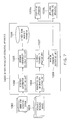
- FIG. 1 shows an exemplary overall configuration of a system including an in-room probability estimating apparatus according to the embodiment.
- This system includes human body detecting sensors 101 , an in-room probability estimating apparatus 100 , a displaying apparatus 109 a and an appliance controlling apparatus 109 b.
- the in-room probability estimating apparatus 100 includes a detection information collecting unit 102 , a movement probability calculating unit 105 , a between-room movement parameter 106 , an in-room probability updating unit 107 and an in-room probability outputting unit 108 .
- the human body detecting sensors 101 are installed in each room within doors.
- the human body detecting sensor 101 detects an action of a human body in the detection range. Once detecting an action of a human body, the human body detecting sensor 101 outputs detection information.
- As the human body detecting sensor 101 for example, a pyroelectric sensor and the like can be used.
- the human body detecting sensor 101 sends the detected information to the detection information collecting unit 102 .
- timing of the sending various methods are possible. It may be sent at regular intervals, may be sent whenever the detection happens, or may be sent in response to a request from the detection information collecting unit 102 .
- the range of the data to be sent may be only a difference from the last time, all after a certain previous time, or others.
- the human body detecting sensor 101 may have a storage in which the detected information is stored.
- the human body detecting sensor 101 may store, in the storage, the information detected in the past, in time series.
- the human body detection information the information showing that a user has operated an appliance, or the information obtained by processing sensor information such as a camera image and others, may be collected from apparatuses installed in rooms, or apparatuses separately installed inside or outside a house, and be utilized.
- the human body detecting sensor 101 is an example of an external apparatus that detects and acquires the human body detection information.
- FIG. 3 shows an exemplary arrangement of the human body detecting sensors.
- the human body detecting sensors A, B, C, D are arranged in rooms A, B, C, D, respectively.
- the hatched circular regions represent the detection ranges of the human body detecting sensors. It is possible to move between the arrow-marked rooms and pass through the room A and the outdoor O.
- the embodiment can be also implemented by excluding the outdoor O and targeting only the indoor rooms.
- the detection information collecting unit 102 collects the detection information from the human body detecting sensors 101 .
- the collecting method may be any method. For example, it is allowable to collect only the information newly produced at regular time intervals, to receive the information whenever the detection by the sensor is newly performed, or to collect all the information after a certain previous time.
- the detection information collecting unit 102 may store the collected information in the storage, and thereby generate a history of the detection information.
- the detection information collecting unit 102 sends, to the movement probability calculating unit 105 , the information necessary for the calculation, based on the collected information. For example, for each sensor, the information containing the latest detection time and the identifier of the sensor is sent. As for the outdoor, an outdoor sensor is virtually assumed, and the information containing the current time (calculation time) and the identifier is sent as the information of the outdoor sensor (that is, it is assumed that the outdoor sensor continues to detect a human body at all times).
- the between-room movement parameter 106 is a parameter showing the hardness of movement between rooms. In advance, an initial value is given to the between-room movement parameter. The between-room movement parameter 106 is determined for every two-room combination. FIG. 11 shows an example of the between-room movement parameters 106 .
- a higher parameter value means that it is harder to move between the rooms (it takes more time to move).
- the bidirectional values between two rooms are both the same value, but may be different values from each other.
- the hardness of movement can be basically regarded as the movement distance between rooms, and the value of the parameter can be determined depending on the distance between rooms. The value of the parameter may be determined in consideration of another factor such as the existence or non-existence of an obstacle.
- the movement probability calculating unit 105 calculates the movement probabilities between rooms, at which at least one or any one of individual persons moves, using the information sent from the detection information collecting unit 102 and the between-room movement parameter 106 .
- the movement probabilities between the two rooms are bi-directionally calculated, based on the difference between the detection times by the human body detecting sensors in the two rooms and the movement parameter between the two rooms.
- the movement probability calculating unit 105 sends the calculated movement probabilities between two rooms to the in-room probability updating unit 107 .
- the in-room probability updating unit 107 calculates the in-room probability for each room on an individual person basis.
- the movement probabilities between each two rooms are calculated on an individual person basis, based on the movement probabilities calculated by the movement probability calculating unit 105 and the in-room probability for each room of each individual person (the value calculated last time, and an initial value is given at first).
- the movement probability from each room to each of the other rooms (a first movement probability) and the movement probability from each of the other rooms to each room (a second movement probability) are calculated.
- the in-room probability for each room is updated on an individual person basis by subtracting the first movement probability from the in-room probability for each room and adding the second movement probability. Thereby, the in-room probability for each room is obtained on an individual person basis.
- the in-room probability updating unit 107 sends the updated in-room probability to the in-room probability outputting unit 108 .
- a label such as X, Y or Z.
- the in-room probability on a room basis may be calculated from the in-room probability for each room of each individual person and be sent to the in-room probability outputting unit 108 .
- the in-room probability outputting unit 108 sends the in-room probability for each room of each individual person calculated by the in-room probability updating unit 107 , to the displaying apparatus 109 a and the appliance controlling apparatus 109 b.
- the displaying apparatus 109 a is a displaying apparatus such as a television, a PC monitor, a tablet computer or a mobile phone.
- the displaying apparatus 109 a displays the in-room probability for each room of each individual person sent by the in-room probability outputting unit 108 . Thereby, the in-room probability for each room of each individual person is visualized.
- FIG. 12 shows an example of the displaying.
- the in-room probability for the outdoor (the room O) is 0.
- the appliance controlling apparatus 109 b is a household electrical or housing appliance that is a controlled object, such as an air conditioner or a light.
- the appliance controlling apparatus 109 b executes an automatic appliance control, such as a prevention control for failure to turn off a power, using the in-room probability for each room of each individual person sent by the in-room probability outputting unit 108 . For example, if all the in-room probabilities of the individual persons for a room are a threshold value or less, the appliance in the room is turned off.
- the configuration of the in-room probability estimating apparatus shown in FIG. 1 can be implemented, for example, by using a general computing apparatus as basic hardware, as shown in FIG. 2 .
- the general computing apparatus (the in-room probability estimating apparatus) 200 includes a CPU 202 , an inputting unit 203 , a displaying unit 204 , a communicating unit 205 , a main storage 206 and an external storage 207 , and the units are mutually connected by a bus 201 .
- the inputting unit 203 includes inputting devices such as a keyboard and a mouse, and outputs an operation signal by an operation of the inputting devices, to the CPU 202 .
- the displaying unit 204 includes a display such as an LCD (Liquid Crystal Display) or a CRT (Cathode Ray Tube).
- a display such as an LCD (Liquid Crystal Display) or a CRT (Cathode Ray Tube).
- the communicating unit 205 has a communication scheme such as Ethernet (R), wireless LAN (Local Area Network) or Bluetooth (R), and communicates with human body detecting sensors 208 .
- a communication scheme such as Ethernet (R), wireless LAN (Local Area Network) or Bluetooth (R)
- the external storage 207 is constituted by a storage medium such as a hard disk, a CD-R, a CD-RW, a DVD-RAM or a DVD-R, and the like, and stores a control program with which the CPU 202 executes the processes by the above detection information collecting unit 102 , movement probability calculating unit 105 , in-room probability updating unit 107 and in-room probability outputting unit 108 .
- the main storage 206 which is constituted by a memory and the like, expands the control program stored in the external storage 207 and stores data necessary at the time of execution of the program, data generated by execution of the program, and the like, under the control by the CPU 202 .
- the in-room probability estimating apparatus may be implemented by previously installing the above control program on the computing apparatus, or by arbitrarily installing the above program that is stored in a storage medium such as a CD-ROM or is distributed via a network, on the computing apparatus.
- the between-room movement parameter 106 in FIG. 11 can be implemented by appropriately using a memory or hard disk such as the main storage 206 or external storage 207 that is incorporated in or externally attached to the above computing apparatus, a storage medium such as a CD-R, a CD-RW, a DVD-RAM or a DVD-R, or the like.
- a printer for printing the information stored in the between-room movement parameter 106 , an abnormality notification and the like may be included.
- the configuration of the in-room probability estimating apparatus shown in FIG. 2 may be modified depending on a target appliance whose usage condition is collected.
- step S 401 when being powered on, first of all, step S 401 is started.
- the detection information of human bodies is acquired from the human body detecting sensors 101 .
- the above-described methods can be used.
- step S 402 a calculating process of the movement probability between rooms (a movement probability calculating process) is performed. The details will be described later using FIG. 5 .
- step S 403 a calculating process of the in-room probability for each room of each individual person (an in-room probability updating process) is performed. The details will be described later using FIG. 6 .
- step S 404 the in-room probability for each room of each individual person calculated in step S 403 is output to one or both of the displaying apparatus 109 a and the appliance controlling apparatus 109 b.
- step S 401 to S 404 For periodically performing the processes in steps S 401 to S 404 , the flow returns to step S 401 at regular time intervals (for example, every one second), and the processes in the above steps are repeatedly executed.
- step S 406 when an end instruction is input from a user, or when an abnormality occurs in a process, the flow is ended (step S 406 ).
- FIG. 5 shows a flowchart of the behavior of the movement probability calculating unit 105 .
- step S 501 is started.
- step S 501 one combination (“i, j”) of rooms is selected, and the difference between the detection time for the room “i” and the detection time for the room “j”, that is, the detection time difference “ ⁇ ij” between the rooms is calculated.
- FIG. 10 shows an example of the detection time difference.
- the detection time for example, for each sensor, the time when the latest detection was performed (the latest detection time) can be used.
- the difference “ ⁇ AB ” between the latest detection time for the room A and the latest detection time for the room B is calculated.
- the “t” in the figure represents the calculation time at the current moment (the current time).
- a filtering process for noise reduction may be performed for a sequence of detection signals.
- a certain detection signal is treated as a noise and deleted when other detection signals are not present near the signal in the past and future (when the signal is present in isolation). This is because it is generally assumed that when a person acts in the detection range of a sensor, multiple detections intermittently continue to some degree (see the sensor signals for the room A in FIG. 10 ).
- step S 502 the movement probability “qij” between the rooms is calculated based on the detection time difference “ ⁇ ij” and the movement parameter “Tij” between the rooms.
- the “Tij” represents the movement parameter from the room “i” to the room “j”
- the “qij” represents the movement probability from the room “i” to the room “j”, at which at least one or any one of individual persons moves.
- An example of a calculation expression of the movement probability “qij” is shown by the following Expression 1.
- the “N( ⁇ , ⁇ )” represents a normal distribution with the average “ ⁇ ” and the standard deviation “ ⁇ ”, and the “N(x; ⁇ , ⁇ )” represents a probability when the value of the variable along the abscissa in the normal distribution is “x”.
- the “ ⁇ ” is given in advance.
- the detection time difference “ ⁇ ij” coincides with the movement parameter, the highest probability is exhibited, and the larger the difference (“ ⁇ ij ⁇ Tij”) is, the lower the probability is.
- the detection time difference “ ⁇ ij” is smaller than the movement parameter, the probability is 0.
- the “t” represents a calculation time (current time), and the value is incremented whenever the flow in FIG. 4 is repeated.
- step S 503 a judgment on whether step S 501 and step S 502 have been performed for all of the two-room combinations of the rooms is made. If step S 501 and step S 502 have been performed for all the combinations, the process in the flow is ended. Otherwise, the flow returns to step S 501 .
- FIG. 6 shows a flowchart of the behavior of the in-room probability updating unit 107 .
- step S 601 the movement probability “ ⁇ ij a ” from the room “i” to the room “j” on an individual person “a” basis is calculated by the following Expression 2.
- ⁇ ij a ⁇ ( t ) p j a ⁇ ( t - 1 ) ⁇ a ⁇ ⁇ p j a ⁇ ( t - 1 ) ⁇ q ij ⁇ ( t ) Expression ⁇ ⁇ 2
- the “p j a ” represents the in-room probability of an individual person “a” for the room “j”.
- the “ ⁇ a ” represents the sum total of the in-room probabilities “p j a ” of all individual persons “a” for the room “j”.
- the “t ⁇ 1” represents the last calculation time.
- the ratio of the last in-room probability “p j a (t ⁇ 1)” of each individual person to the sum total “ ⁇ a p j a (t ⁇ 1)” of the last in-room probabilities for the room “j” is multiplied by the current movement probability “qij” between the rooms. That is, by giving the “p j a (t ⁇ 1)” as the weight of each individual person and distributing the movement probability “qij” among the individual persons, the movement probability “ ⁇ ij a ” between the rooms of each individual person is obtained.
- a parameter that determines an upper limit number of persons to be treated in the system is given in advance. In the process of the step, the calculation may be performed assuming that there are an upper limit number of persons. Naturally, in the case of knowing the maximum number of persons who can be present within doors, it is possible to set the person number and perform a calculation with the set person number. Also, a person number may be fixed on the assumption that nobody goes in and out of the outdoor.
- step S 602 the movement probability “ ⁇ ij a ” between the rooms calculated in step S 601 is subtracted from the in-room probability for the room “i”, and thereby the in-room probability for the room “i” is updated. This is performed on an individual person basis.
- An example of the update expression is shown by Expression 3.
- p i a ( t ) p i a ( t ⁇ 1) ⁇ ij a ( t )
- step S 603 the in-room probability for each room of each individual person updated in step S 602 is compared with a threshold value.
- the in-room probabilities for rooms with the threshold value or less are set to 0, and a normalization is performed such that the in-room probabilities for the other rooms sum up to 1 (even after the normalization, the in-room probabilities for rooms with the threshold value or less are 0). This increases the availability of the data.
- step S 404 of FIG. 4 the in-room probability for each room of each individual person is sent to the displaying apparatus 109 a , the appliance controlling apparatus 109 b , or both of them.
- the embodiment it is possible to estimate the in-room probability for each room, using human body detecting sensors. Since situations of in-room presence and absence can be estimated as probabilities, it is possible to perform power-saving advice and automatic appliance control in consideration of a medium between in-room presence and absence.
- the use of human body detecting sensors lowers the costs and reduces the problem with privacy.
- FIG. 7 shows an exemplary overall configuration of a system including an in-room probability estimating apparatus according to the embodiment.
- This system includes human body detecting sensors 1001 , an in-room probability estimating apparatus 1000 , a displaying apparatus 1009 a , an appliance controlling apparatus 1009 b , and portable wireless identifying devices 1003 .
- the in-room probability estimating apparatus 1000 includes a detection information collecting unit 1002 , an identification information collecting unit 1004 , a movement probability calculating unit 1005 , a between-room movement parameter 1006 , an in-room probability updating unit 1007 and an in-room probability outputting unit 1008 .
- the major difference from the first embodiment is that the portable wireless identifying devices 1003 and the identification information collecting unit 1004 are added, Hereinafter, the difference from the first embodiment will be mainly described, and descriptions for repetitive parts are omitted.
- the portable wireless identifying device 1003 is a portable device, such as a smartphone or a RFID tag, that includes a wireless communicating mechanism such as Wi-Fi, Bluetooth or ZigBee.
- the portable wireless identifying device 1003 is carried by an individual person.
- the portable wireless identifying device 1003 wirelessly sends the identification information of the device, to the identification information collecting unit 1004 .
- the identification information collecting unit 1004 collects the identification information sent from the portable wireless identifying device 1003 .
- the collecting method may be any method. For example, at regular time intervals, the identification information is collected from the portable wireless identifying device 1003 . When the length of the regular time interval is shorter than the calculation interval in the process shown in FIG. 4 , a more accurate estimation is possible.
- the identification information collecting unit 1004 is provided in each room, and sends its own identification information and the collected device identification information, to the in-room probability updating unit 1007 . Thereby, the in-room probability updating unit 1007 manages, in an internal buffer, rooms where portable wireless devices are present. The information about the correspondence between the portable wireless device and the holder name may be further managed.
- the identification information collecting unit 1004 may be a wireless access point, for example. In the case where the detection area of the identification information collecting unit 1004 is large, there is a possibility of detection of the device even by the identification information collecting unit 1004 in another room. In such a case, a room where the portable wireless device is present may be determined depending on the reception field intensity.
- FIG. 8 shows a flowchart of the behavior of the in-room probability updating unit 1007 .
- Steps S 1101 , S 1102 and S 1103 are the same as steps S 601 , S 602 and S 603 in FIG. 6 .
- step S 1104 when the room shown by the identification information of the identification information collecting unit 1004 is “i”, a person “a” who exhibits the highest value in the in-room probability “p i a ” for the room “i” is selected. As for the person “a”, the in-room probability for the room “i” is increased, and the probabilities for the other rooms are decreased. For example, the in-room probability for the room “i” is set to 1, and the probabilities for the other rooms are set to 0. This increases the availability of the data. It is possible to give the correspondence between the identification information of the wireless identifying device and the identification information of the holder (i.e., a user holding the device), and using this, identify the actual individual person.
- FIG. 9 shows an exemplary hardware configuration of the system shown in FIG. 7 .
- the computing apparatus (the in-room probability estimating apparatus) 1200 includes a CPU 1202 , an inputting unit 1203 , a displaying unit 1204 , a communicating unit 1205 , a main storage 1206 and an external storage 1207 , and the units are mutually connected by a bus 1201 .
- the communicating unit 1205 communicates with not only the human body detecting sensors 1208 but also the wireless identifying devices 1209 .
- the others are the same as the first embodiment, and therefore, the descriptions are omitted.
- the portable wireless identifying device such as a smartphone
- the in-room probability is estimated with a combination of the human body detecting sensor and the portable wireless identifying device, a minimum of power-saving advice and automatic appliance control are possible, even when some persons do not hold the portable wireless identifying device (for example, when having a visitor, or when forgetting to hold the portable device).
Abstract
Description
p i a(t)=p i a(t−1)−Δij a(t)
p j a(t)=p j a(t−1)+Δij a(t)
Claims (10)
Applications Claiming Priority (2)
| Application Number | Priority Date | Filing Date | Title |
|---|---|---|---|
| JP2013-058655 | 2013-03-21 | ||
| JP2013058655A JP6148505B2 (en) | 2013-03-21 | 2013-03-21 | Occupancy probability estimation device, method thereof, and program |
Publications (2)
| Publication Number | Publication Date |
|---|---|
| US20140285348A1 US20140285348A1 (en) | 2014-09-25 |
| US9116515B2 true US9116515B2 (en) | 2015-08-25 |
Family
ID=50554953
Family Applications (1)
| Application Number | Title | Priority Date | Filing Date |
|---|---|---|---|
| US14/206,209 Expired - Fee Related US9116515B2 (en) | 2013-03-21 | 2014-03-12 | In-room probability estimating apparatus, method therefor and program |
Country Status (4)
| Country | Link |
|---|---|
| US (1) | US9116515B2 (en) |
| JP (1) | JP6148505B2 (en) |
| FR (1) | FR3003666A1 (en) |
| GB (1) | GB2514230B (en) |
Families Citing this family (6)
| Publication number | Priority date | Publication date | Assignee | Title |
|---|---|---|---|---|
| US20150005951A1 (en) * | 2013-06-30 | 2015-01-01 | Enlighted, Inc. | Flooring sensors for occupant detection |
| CN109416192B (en) * | 2016-07-07 | 2021-04-16 | 三菱电机株式会社 | Air conditioning control device, air conditioning control method, air conditioning system, and house with air conditioning |
| KR102437138B1 (en) * | 2016-08-01 | 2022-08-29 | 주식회사 직방 | Method and apparatus for profiling a pattern of resident by analyzing event log |
| WO2020053924A1 (en) * | 2018-09-10 | 2020-03-19 | 三菱電機株式会社 | Air conditioning management server device, air conditioning management program, and air conditioning management method |
| CN110149500A (en) * | 2019-05-24 | 2019-08-20 | 深圳市珍爱云信息技术有限公司 | Processing method, device, equipment and the storage medium of monitor video |
| CN112413852B (en) * | 2020-12-02 | 2022-04-12 | 珠海格力电器股份有限公司 | Method and device for controlling air conditioning equipment and air conditioning equipment |
Citations (17)
| Publication number | Priority date | Publication date | Assignee | Title |
|---|---|---|---|---|
| US5335180A (en) * | 1990-09-19 | 1994-08-02 | Hitachi, Ltd. | Method and apparatus for controlling moving body and facilities |
| US20070003141A1 (en) * | 2005-06-30 | 2007-01-04 | Jens Rittscher | System and method for automatic person counting and detection of specific events |
| US20070031005A1 (en) * | 2000-09-06 | 2007-02-08 | Nikos Paragios | Real-time crowd density estimation from video |
| US20070176760A1 (en) * | 2006-01-18 | 2007-08-02 | British Telecommunications | Monitoring movement of an entity in an environment |
| JP2008077361A (en) | 2006-09-20 | 2008-04-03 | Kanazawa Inst Of Technology | Monitoring method and monitoring system |
| JP2009250589A (en) | 2008-04-10 | 2009-10-29 | Takenaka Komuten Co Ltd | Personal air conditioning system |
| JP2010237890A (en) | 2009-03-31 | 2010-10-21 | Toshiba Corp | Device and method for estimating number of in-room staying persons |
| US20100299116A1 (en) * | 2007-09-19 | 2010-11-25 | United Technologies Corporation | System and method for occupancy estimation |
| US20110007944A1 (en) * | 2007-09-19 | 2011-01-13 | Vadim Atrazhev | System and method for occupancy estimation |
| US20110130881A1 (en) | 2009-12-01 | 2011-06-02 | Denso Wave Incorporated | Central air-conditioning system |
| US20110213588A1 (en) * | 2008-11-07 | 2011-09-01 | Utc Fire & Security | System and method for occupancy estimation and monitoring |
| JP2012099136A (en) | 2012-01-10 | 2012-05-24 | Toshiba Corp | Estimation device and estimation method for number of persons in room |
| US20120209567A1 (en) | 2009-09-03 | 2012-08-16 | Shuichiro Imahara | Existent person count estimation apparatus |
| US20120237086A1 (en) * | 2009-12-03 | 2012-09-20 | National Institute Of Advanced Industrial Science And Technology | Moving body positioning device |
| EP2592586A1 (en) | 2011-11-14 | 2013-05-15 | Siemens Aktiengesellschaft | Person flow simulation with waiting zones |
| US20130329958A1 (en) * | 2011-03-28 | 2013-12-12 | Nec Corporation | Person tracking device, person tracking method, and non-transitory computer readable medium storing person tracking program |
| US20140091936A1 (en) * | 2011-03-17 | 2014-04-03 | University Of Strathclyde | Occupancy Detection System |
Family Cites Families (5)
| Publication number | Priority date | Publication date | Assignee | Title |
|---|---|---|---|---|
| IT1291064B1 (en) * | 1997-02-14 | 1998-12-14 | Euroclima Di Avalle E Cravero | BUILDING ROOM HEATING SYSTEM. |
| WO2002029749A1 (en) * | 2000-09-26 | 2002-04-11 | Matsushita Electric Industrial Co., Ltd. | Object status detector, object status detecting method, home electric appliances, network adopter, and media |
| JP4455417B2 (en) * | 2005-06-13 | 2010-04-21 | 株式会社東芝 | Mobile robot, program, and robot control method |
| EP2184724A1 (en) * | 2008-11-05 | 2010-05-12 | Nederlandse Organisatie voor toegepast-natuurwetenschappelijk Onderzoek TNO | A system for tracking a presence of persons in a building, a method and a computer program product |
| JP5691918B2 (en) * | 2011-07-28 | 2015-04-01 | 富士通株式会社 | Absence duration estimation method, absence absence duration estimation program, and absence absence duration estimation device |
-
2013
- 2013-03-21 JP JP2013058655A patent/JP6148505B2/en not_active Expired - Fee Related
-
2014
- 2014-03-12 US US14/206,209 patent/US9116515B2/en not_active Expired - Fee Related
- 2014-03-12 GB GB1404368.1A patent/GB2514230B/en not_active Expired - Fee Related
- 2014-03-12 FR FR1452029A patent/FR3003666A1/en not_active Withdrawn
Patent Citations (17)
| Publication number | Priority date | Publication date | Assignee | Title |
|---|---|---|---|---|
| US5335180A (en) * | 1990-09-19 | 1994-08-02 | Hitachi, Ltd. | Method and apparatus for controlling moving body and facilities |
| US20070031005A1 (en) * | 2000-09-06 | 2007-02-08 | Nikos Paragios | Real-time crowd density estimation from video |
| US20070003141A1 (en) * | 2005-06-30 | 2007-01-04 | Jens Rittscher | System and method for automatic person counting and detection of specific events |
| US20070176760A1 (en) * | 2006-01-18 | 2007-08-02 | British Telecommunications | Monitoring movement of an entity in an environment |
| JP2008077361A (en) | 2006-09-20 | 2008-04-03 | Kanazawa Inst Of Technology | Monitoring method and monitoring system |
| US20110007944A1 (en) * | 2007-09-19 | 2011-01-13 | Vadim Atrazhev | System and method for occupancy estimation |
| US20100299116A1 (en) * | 2007-09-19 | 2010-11-25 | United Technologies Corporation | System and method for occupancy estimation |
| JP2009250589A (en) | 2008-04-10 | 2009-10-29 | Takenaka Komuten Co Ltd | Personal air conditioning system |
| US20110213588A1 (en) * | 2008-11-07 | 2011-09-01 | Utc Fire & Security | System and method for occupancy estimation and monitoring |
| JP2010237890A (en) | 2009-03-31 | 2010-10-21 | Toshiba Corp | Device and method for estimating number of in-room staying persons |
| US20120209567A1 (en) | 2009-09-03 | 2012-08-16 | Shuichiro Imahara | Existent person count estimation apparatus |
| US20110130881A1 (en) | 2009-12-01 | 2011-06-02 | Denso Wave Incorporated | Central air-conditioning system |
| US20120237086A1 (en) * | 2009-12-03 | 2012-09-20 | National Institute Of Advanced Industrial Science And Technology | Moving body positioning device |
| US20140091936A1 (en) * | 2011-03-17 | 2014-04-03 | University Of Strathclyde | Occupancy Detection System |
| US20130329958A1 (en) * | 2011-03-28 | 2013-12-12 | Nec Corporation | Person tracking device, person tracking method, and non-transitory computer readable medium storing person tracking program |
| EP2592586A1 (en) | 2011-11-14 | 2013-05-15 | Siemens Aktiengesellschaft | Person flow simulation with waiting zones |
| JP2012099136A (en) | 2012-01-10 | 2012-05-24 | Toshiba Corp | Estimation device and estimation method for number of persons in room |
Non-Patent Citations (1)
| Title |
|---|
| Office Action issued Sep. 12, 2014 in United Kingdom Patent Application No. GB1404368.1. |
Also Published As
| Publication number | Publication date |
|---|---|
| GB2514230B (en) | 2018-01-31 |
| JP6148505B2 (en) | 2017-06-14 |
| JP2014183553A (en) | 2014-09-29 |
| GB2514230A (en) | 2014-11-19 |
| FR3003666A1 (en) | 2014-09-26 |
| GB201404368D0 (en) | 2014-04-23 |
| US20140285348A1 (en) | 2014-09-25 |
Similar Documents
| Publication | Publication Date | Title |
|---|---|---|
| US9116515B2 (en) | In-room probability estimating apparatus, method therefor and program | |
| Candanedo et al. | Accurate occupancy detection of an office room from light, temperature, humidity and CO2 measurements using statistical learning models | |
| US20200250774A1 (en) | System and method for predictive cleaning | |
| US8630745B2 (en) | Energy consumption management system and energy consumption management apparatus | |
| US20180292520A1 (en) | Occupancy Estimation Using Nonparametric Online Change-Point Detection, and Apparatuses, Systems, and Software for Same | |
| AU2019288483B2 (en) | Device location network | |
| JP5162030B2 (en) | Existence number estimation device | |
| US10416143B2 (en) | Devices and methods for determining and acting upon cumulative exposure of a building occupant to a hazardous substance | |
| Azimi et al. | Fit-for-purpose: Measuring occupancy to support commercial building operations: A review | |
| US10939273B1 (en) | Systems and methods for notifying particular devices based on estimated distance | |
| EP3196854A1 (en) | Indoor activity detection based on tag tracking | |
| JP2011133164A (en) | Device and method for estimating person number | |
| JP2018048749A (en) | Estimation device, estimation system, estimation method and estimation program | |
| JP2016163193A (en) | Living body detection result utilization system | |
| US20240000376A1 (en) | Processing Radio Frequency Wireless Signals in a Motion Detection System | |
| EP2911018A1 (en) | Building automation system using a predictive model | |
| JP2017117141A (en) | Guard business support system and guard device | |
| EP3905211A1 (en) | Systems and methods for notifying particular devices based on estimated distance | |
| US20180156483A1 (en) | Control of an environmental condition manipulating appliance | |
| EP3933792A1 (en) | Systems and methods for location-based electronic fingerprint detection | |
| US20230351882A1 (en) | Systems and methods for pattern recognition and individual detection | |
| WO2020199077A1 (en) | Building management system using video analytics | |
| KR20160018920A (en) | Apparatus and method for controlling environment of building |
Legal Events
| Date | Code | Title | Description |
|---|---|---|---|
| AS | Assignment |
Owner name: KABUSHIKI KAISHA TOSHIBA, JAPAN Free format text: ASSIGNMENT OF ASSIGNORS INTEREST;ASSIGNORS:IMAHARA, SHUICHIRO;YANO, TORU;TAKEUCHI, RYOSUKE;REEL/FRAME:032617/0446 Effective date: 20140326 |
|
| STCF | Information on status: patent grant |
Free format text: PATENTED CASE |
|
| MAFP | Maintenance fee payment |
Free format text: PAYMENT OF MAINTENANCE FEE, 4TH YEAR, LARGE ENTITY (ORIGINAL EVENT CODE: M1551); ENTITY STATUS OF PATENT OWNER: LARGE ENTITY Year of fee payment: 4 |
|
| FEPP | Fee payment procedure |
Free format text: MAINTENANCE FEE REMINDER MAILED (ORIGINAL EVENT CODE: REM.); ENTITY STATUS OF PATENT OWNER: LARGE ENTITY |
|
| LAPS | Lapse for failure to pay maintenance fees |
Free format text: PATENT EXPIRED FOR FAILURE TO PAY MAINTENANCE FEES (ORIGINAL EVENT CODE: EXP.); ENTITY STATUS OF PATENT OWNER: LARGE ENTITY |
|
| STCH | Information on status: patent discontinuation |
Free format text: PATENT EXPIRED DUE TO NONPAYMENT OF MAINTENANCE FEES UNDER 37 CFR 1.362 |
|
| FP | Lapsed due to failure to pay maintenance fee |
Effective date: 20230825 |