US9110295B2 - System and method of controlling discharge of a firearm - Google Patents
System and method of controlling discharge of a firearm Download PDFInfo
- Publication number
- US9110295B2 US9110295B2 US13/384,338 US201113384338A US9110295B2 US 9110295 B2 US9110295 B2 US 9110295B2 US 201113384338 A US201113384338 A US 201113384338A US 9110295 B2 US9110295 B2 US 9110295B2
- Authority
- US
- United States
- Prior art keywords
- muzzle
- firearm
- trigger
- scope
- designation point
- Prior art date
- Legal status (The legal status is an assumption and is not a legal conclusion. Google has not performed a legal analysis and makes no representation as to the accuracy of the status listed.)
- Expired - Fee Related
Links
Images


Classifications
-
- F—MECHANICAL ENGINEERING; LIGHTING; HEATING; WEAPONS; BLASTING
- F41—WEAPONS
- F41G—WEAPON SIGHTS; AIMING
- F41G3/00—Aiming or laying means
- F41G3/005—Aiming or laying means with means for correcting the parallax between the sighting means and the muzzle axis
-
- G—PHYSICS
- G02—OPTICS
- G02B—OPTICAL ELEMENTS, SYSTEMS OR APPARATUS
- G02B23/00—Telescopes, e.g. binoculars; Periscopes; Instruments for viewing the inside of hollow bodies; Viewfinders; Optical aiming or sighting devices
- G02B23/14—Viewfinders
- G02B23/145—Zoom viewfinders
-
- F—MECHANICAL ENGINEERING; LIGHTING; HEATING; WEAPONS; BLASTING
- F41—WEAPONS
- F41A—FUNCTIONAL FEATURES OR DETAILS COMMON TO BOTH SMALLARMS AND ORDNANCE, e.g. CANNONS; MOUNTINGS FOR SMALLARMS OR ORDNANCE
- F41A17/00—Safety arrangements, e.g. safeties
- F41A17/06—Electric or electromechanical safeties
-
- F—MECHANICAL ENGINEERING; LIGHTING; HEATING; WEAPONS; BLASTING
- F41—WEAPONS
- F41A—FUNCTIONAL FEATURES OR DETAILS COMMON TO BOTH SMALLARMS AND ORDNANCE, e.g. CANNONS; MOUNTINGS FOR SMALLARMS OR ORDNANCE
- F41A19/00—Firing or trigger mechanisms; Cocking mechanisms
- F41A19/06—Mechanical firing mechanisms, e.g. counterrecoil firing, recoil actuated firing mechanisms
- F41A19/10—Triggers; Trigger mountings
-
- F—MECHANICAL ENGINEERING; LIGHTING; HEATING; WEAPONS; BLASTING
- F41—WEAPONS
- F41A—FUNCTIONAL FEATURES OR DETAILS COMMON TO BOTH SMALLARMS AND ORDNANCE, e.g. CANNONS; MOUNTINGS FOR SMALLARMS OR ORDNANCE
- F41A19/00—Firing or trigger mechanisms; Cocking mechanisms
- F41A19/58—Electric firing mechanisms
-
- F—MECHANICAL ENGINEERING; LIGHTING; HEATING; WEAPONS; BLASTING
- F41—WEAPONS
- F41A—FUNCTIONAL FEATURES OR DETAILS COMMON TO BOTH SMALLARMS AND ORDNANCE, e.g. CANNONS; MOUNTINGS FOR SMALLARMS OR ORDNANCE
- F41A27/00—Gun mountings permitting traversing or elevating movement, e.g. gun carriages
- F41A27/30—Stabilisation or compensation systems, e.g. compensating for barrel weight or wind force on the barrel
-
- F—MECHANICAL ENGINEERING; LIGHTING; HEATING; WEAPONS; BLASTING
- F41—WEAPONS
- F41C—SMALLARMS, e.g. PISTOLS, RIFLES; ACCESSORIES THEREFOR
- F41C27/00—Accessories; Details or attachments not otherwise provided for
- F41C27/22—Balancing or stabilising arrangements on the gun itself, e.g. balancing weights
-
- F—MECHANICAL ENGINEERING; LIGHTING; HEATING; WEAPONS; BLASTING
- F41—WEAPONS
- F41G—WEAPON SIGHTS; AIMING
- F41G1/00—Sighting devices
- F41G1/38—Telescopic sights specially adapted for smallarms or ordnance; Supports or mountings therefor
-
- F—MECHANICAL ENGINEERING; LIGHTING; HEATING; WEAPONS; BLASTING
- F41—WEAPONS
- F41G—WEAPON SIGHTS; AIMING
- F41G3/00—Aiming or laying means
- F41G3/06—Aiming or laying means with rangefinder
-
- F—MECHANICAL ENGINEERING; LIGHTING; HEATING; WEAPONS; BLASTING
- F41—WEAPONS
- F41G—WEAPON SIGHTS; AIMING
- F41G3/00—Aiming or laying means
- F41G3/12—Aiming or laying means with means for compensating for muzzle velocity or powder temperature with means for compensating for gun vibrations
Definitions
- This description relates to ballistic muzzle tracking and related devices, and especially to telescopic ballistic sights to achieve medium and long-range accuracy in the presence of normal human tremor.
- PCT application WO8102925 A1 describes a rifle with a stabilizing structure that receives the arm of the user so that forces are exerted upon the stabilizing structure by various surfaces of the shoulder or upper arm of the shooter.
- a method for using a firearm or air gun sighting scope for automated compensation of human unsteadiness during firing of firearms or air guns including at least the steps of: aiming the firearm or air gun on a desired target and initiating action to create a designation point and activate muzzle tracking; initiating firing of the firearm or air gun device, which fires only when the angular motion deviation of the firearm or air gun muzzle from the angular position designation point are below an acceptable level.
- the designation point remains fixed in the field of view.
- a trigger pull is resisted or inflated while the angular motion deviations of the firearm or air gun muzzle from the angular position designation point are above an acceptable level.
- a firearm or air gun sighting scope system for automatic compensation of human unsteadiness during firing of firearms or air guns using an angular position designation point
- a muzzle tracking module wherein said muzzle tracking module tracks angular motion deviations of the firearm or air gun muzzle from the angular position designation point
- a synchronized trigger mechanism that enables firing of the firearm or air gun when the angular motion deviations of the firearm or air gun muzzle from the angular position designation point is below an acceptable level and prevents or impedes firing when the angular motion deviation of the firearm or air gun muzzle from the angular position designation point is above the acceptable level.
- the muzzle-tracking module of the firearm or air gun sighting scope system includes at least an image sensor, an inclinometer; and gyroscopes.
- the synchronized trigger mechanism of the firearm or air gun sighting scope system includes at least a solenoid to prevent firing when angular deviation of the muzzle from the angular position designation point is above an acceptable level.
- the synchronized trigger mechanism of the firearm or air gun sighting scope system includes at least a nitinol wire variable force trigger to prevent firing when angular deviation of the muzzle from the angular position designation point is above the acceptable level.
- the synchronized trigger mechanism of the firearm or air gun sighting scope system includes at least a safety switch to prevent firing when angular deviation of the muzzle from the angular position designation point is above an acceptable level; an electrically activated primer; a bolt with an internal electrical contact for electrical connection to the electrically activated primer; and an electronic activation circuit for activation of the electrically activated primer.
- the firearm or air gun sighting scope system for automatic compensation of human unsteadiness during firing of firearm or air gun devices also includes at least an automatic ballistics cross-hair that is computationally generated and automatically re-positioned in the field of view based on target range, bullet ballistics, wind, and muzzle incline/decline.
- FIG. 1 is a rendering of an embodiment of the firearm or air gun sighting scope.
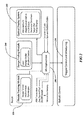
- FIG. 2 is a schematic of functional subsystems of the firearm or air gun sighting scope system.
- FIG. 3 is a cutaway view of an embodiment of the firearm or air gun sighting scope.
- FIG. 4 is a rendering of a trigger control embodiment.
- FIG. 5 is a rendering of another trigger control embodiment.
- FIG. 6 is a schematic of the states of the system.
- FIG. 1 is an illustration of an embodiment of the firearm or air gun sighting scope 100 . It appears very similar to other scopes but has very different functionality.
- An elevation knob 140 has an electronic button 150 .
- a windage knob 120 also has an electronic button 130 .
- an optical zoom adjustment is shown as 110 .
- FIG. 2 is a schematic representation of the subsystems with the two major parts shown as the advanced intelligent firearm or air gun scope (Scope) in the top half of the representation that provides all of the functionality of attitude tracking, and the Trigger Monitoring and Control (TMC), represented in the bottom half (Ballistic Device) that provides firing synchronization.
- Scope advanced intelligent firearm or air gun scope
- TMC Trigger Monitoring and Control
- the proposed scope has three major components—a muzzle-tracking module (MTM) 220 , a range finding module 240 and an optical display system 260 .
- the muzzle-tracking module contains an array of gyroscopes and an image sensor for muzzle position tracking and an inclinometer to determine shot angle relative to gravity. All of these feed into a core microprocessor 280 with embedded software that provides the intelligence for the system. All of the microprocessor capability can be supplied with one central microprocessor as shown or that capability could be split between the various modules.
- FIG. 3 is a rendering of the internals of the firearm or air gun sighting scope 300 .
- Range finding module 240 uses a “time of flight” laser range finding approach.
- An off axis infrared laser 350 generates light that is reflected using beam splitters 345 into the scope optical path toward the target.
- Laser light is emitted in timed pulses that illuminate the target.
- the returning reflection from the target is detected by an avalanche photodiode receiver 340 and the time delay is measured to with 1 nanosecond. This time of flight is used to determine the distance to the target.
- the scope also contains an optical display system 260 . It is built around a zoom power scope with zoom lenses 320 , 325 that typically give a 3 ⁇ -12 ⁇ power range but is not limited to that.
- the sighting scope also includes a display beam splitter 335 , and an image sensor 310 . Power is supplied by an internal battery 355 .
- the invention anticipates that the scope can be a video (camera) scope or a natural light scope.
- the optical system projects the reticle, range and configuration screens onto a display 365 in the field of view.
- One aspect of the optical display system is the capability of the shooter to initially position the horizontal and vertical reticles (crosshair) on a potential target and press the shot control button 130 on the windage knob 120 (see FIG. 1 ) to illuminate a colored dot or designation-dot that represents the desired designation point on the target. This is used in shot simulation, muzzle tracking, and trigger synchronization to be described later
- Trigger control and monitoring 290 is separate from the scope, as shown in FIG. 2 .
- the proposed scope can mount on any firearm or air gun device, including various rifles and bows.
- TMC Trigger Monitor and Control
- TMC One embodiment of the TMC capability in shown in FIG. 4 as system 400 which includes 1) a solenoid 440 with proximity switch 430 that functions to restrict firing when off target, and 2) internal wiring and connector to connect the solenoid to the scope.
- the TMC includes a two state trigger 415 and shot control switch 410 .
- the mechanism increases the trigger pull force when the solenoid is activated from normal trigger pull force of approximately 2 lbs to a restricting force of about 8 lbs. If the shooter applies more than 8 lbs of force to the trigger, he may fire in spite of the solenoid's restricting force.
- a second embodiment of the TMC capability shown in FIG. 5 as system 500 is a nitinol wire variable force trigger, which consists of 1) a nitinol wire retractor 510 , 2) a wedge pin 530 , 3) a cantilever spring 520 , and 4) a trigger spring 535 .
- This mechanism increases the trigger pull force when the wedge pin is moved between the cantilever spring and trigger sear.
- the trigger pull force of approximately 2 lbs inflates to a restricting force of about 8 lbs. If the shooter applies more than 8 lbs of force to the trigger, he may fire in spite of the spring's restricting force.
- a third embodiment of the TMC (not shown) consists of an electric trigger system consisting of a safety switch, a 2 lbs switch and an 8 lbs switch on the trigger, an electrically activated primer for discharging the firearm, a bolt with an internal electrical contact for electrical connection to the primer and an electronic activation circuit for activation of the primer.
- This circuit performs the same functions typical of a trigger design, including monitoring the safety switch and trigger switches.
- a trigger pull of 8 lbs or more will fire the gun, and a trigger pull of 2 lbs or more but less than 8 lbs will fire the gun only if the gun is aligned with the designation point.
- the scope has three primary capabilities: a direction designation method such as a Shot Simulator, a muzzle tracking method such as the Muzzle Tracking Module to measure angular motion deviations from the designated direction, and a synchronized firing method such as the Trigger Monitor and Control mechanism. Each is described below.
- the proposed scope allows the shooter to quickly and automatically simulate a shot before firing.
- a colored dot (designation-dot) appears in the field-of-view where the horizontal and vertical reticles cross (cross-hair).
- This designation dot or designation point represents the muzzle position at designation time and simulates the point of impact should the shooter pull the trigger. If the shooter is satisfied with the impact point as marked by the designation-dot, he pulls the trigger while endeavoring to keep the cross-hair on the designation-dot.
- the shooter If the shooter is not satisfied with the designated impact point, he attempts to realign the cross hair with his intended impact point, and presses the shot control button again, at which time the designation-dot reappears. The shooter can repeat the simulation multiple times until he is satisfied with the impact point indicated by the designation-dot.
- the cross-hair will move off the simulated point of impact but the designation-dot or designation point will stay fixed with the field of view. This is done by continually monitoring and processing the field-of-view image. Movement in the image represents the rate and direction of muzzle movement.
- the muzzle-tracking module continuously tracks angular motion deviations of the muzzle from the angular position designation point. Using kinematic equations, the microprocessor can then predict when the muzzle will re-intersect the designation point. These kinematic equations take into account angle and direction of muzzle movement and the time it takes for the firing-pin to strike and launch the bullet.
- the trigger pull will be resisted or inflated while the angular motion deviations of the muzzle from the angular position designation point are above an acceptable level, but the trigger resistance will relax or deflate when the cross-hairs approach the designation-dot and the deviation of the muzzle from the angular position designation point are 30 below an acceptable level. This enables firing of the firearm or air gun when the angular motion deviation of the firearm or air gun muzzle from the angular position designation point is at an acceptable level and prevents or impedes firing when the angular motion deviation of the firearm or air gun muzzle from the angular position designation point is above the acceptable level. If the Shot Synchronizer is not in use, the trigger will release when the normal trigger pull-force has been exceeded.
- a typical shooter will introduce human jitter and trigger jerk somewhere between 2 and 15 minutes of angle (MOA). At 500 yards a shooter could miss the target by up to 75 inches or more.
- the Shot Synchronizer limits the impact of human jitter and trigger jerk to 0.8 MOA which is about 4 inches at 500 yards. This type of accuracy is attainable even if the shooter is firing “off-hand” without a gun rest.
- the Shot Synchronizer works in conjunction with the Shot Simulator.
- an actuator in the trigger inflates the trigger pull force (to approximately 8 lbs.) to restrict firing.
- the actuator releases and normal trigger pressure (2 to 3) pounds is overridden by the shooter and the shot is fired.
- the firearm or air guns scope has an embedded laser range finder.
- a laser diode generates a beam of light that is projected out through the scope through a beam splitter.
- the range finder can operate to 800 yards with an accuracy of +/ ⁇ 1.5 yard.
- the range finder can be activated in two ways. With rifles that include the trigger control and monitoring system 290 , the range finder can be activated by pressing the shot control button. For non-trigger control and monitoring system firearm or air gun devices, the range finder is activated by one of the buttons on the firearm or air guns scope.
- the range finder also has a weather station that records wind speed, humidity, and air pressure.
- the reticle on the firearm or air guns scope Prior to shot simulation, the reticle on the firearm or air guns scope is electronically positioned in the field-of-view of the scope. After ranging the shot the positions of the horizontal and vertical axis of the reticle are automatically repositioned in the field-of-view based on target range, bullet ballistics, wind and muzzle incline/decline. The new cross-hair, based on the repositioned reticles, becomes the shooters target alignment point. The reticle is typically not displayed when the gun is not in use. When the gun is moved to roughly a horizontal position the reticle appears.
- the proposed scope includes a plurality of buttons and selection knobs ( FIG. 1 ) that allow the user to configure, manage, and operate the scope. These buttons and knobs are the interface for the user. Some of the variables that can be input through these controls are at least: Power On/Off, shot control button, wind direction and speed, gun type, ammunition type, reticle type, and configuration of other user preferences.
- the windage knob and button on the User Control Interface allow the selection of Configuration Mode.
- This mode displays a menu which is scrolled by twisting the windage knob and selected by pressing the windage knob's button.
- Two additional features are selectable from this menu:—Single-Shot Automatic Alignment Mode and Ammo Select.
- the proposed scope's automatic alignment capability is a significant innovation. Without this capability, a typical shooter may take a dozen or more shots and up to an hour's time aligning the scope with the muzzle. This manual process is often unreliable because of shooter jitter and trigger jerk.
- the proposed scope eliminates the need for mechanical alignment turrets, eliminates the need to know the range of the alignment target and eliminates error due to jitter and jerk.
- the shooter aligns the cross hair on the center of the target and presses the shot control button. If the designation-dot is on the center of the target, the shooter completes the shot by increasing trigger pressure. The shooter then lines up on the target center, presses the shot control button, moves the cross-hairs to where the round impacted the target and again presses the shot control button. The cross hairs then adjust automatically completing alignment.
- the proposed scope is connected to a laptop via a universal serial bus (USB) cable.
- USB universal serial bus
- the scope can download new software, new ammunition information, and new rifle types.
- the proposed scope can operate in Standard mode or Advanced mode. Selection of the mode is made by a switch on the side of the scope.
- Standard mode the reticles are displayed in a default location and only updated from that location if the elevation or windage knobs are moved. This mode emulates the features and actions typically found in a traditional riflescope and therefore does not synchronize the trigger or affect it in any way.
- Advanced mode all the advanced features of the scope are enabled including the Shot Simulator, Muzzle Tracking, Shot Synchronization, Automatic Ballistics Crosshair, and the other advanced features.
- the proposed scope detects when the gun is in a steady shooting position by monitoring the inclinometer and gyroscopes.
- the scope automatically powers up and displays the default reticle.
- a double press of the Shot Control Sutton will generally abort the current action and reset the scope back to showing its default reticle.
- the ballistics scope built-in range finder can range targets up to 800 yards away. In hunting, once the animal is identified, the shooter will find the animal in the scope. He/she will place the cross hair on the animal and press (SCP) the shot control button. The range finder will automatically find the range. The user releases (SCR) the shot control and the range is locked in. The range is displayed in the scope field of view and the range information is used by the scope to set the ballistics reticles. If the shooter ranged on the wrong target or wants to re-start the shooting process for any reason he does a rapid double press. This rapid double press is called the “Reset Action” (SOC). The scope also reverts to the pre-shot state when the rifle is roughly vertical as detected by the inclinometer and gyroscopes.
- Step 2 Taking A Simulated Shot
- the shooter moves the ballistics-adjusted crosshair to the desired designation point on the target and presses (SCP) the shot control button.
- a colored “designation-dot” appears in the field of view. This dot can be any color but is most likely to be set by the user for red or green. This dot is a simulation of where the bullet will impact the target. If the shooter is not satisfied with the simulated shot location he attempts once again to place the colored designation-dot on the target's desired target zone and presses the shot control button again, simulating another shot.
- the shooter can repeat (SCP) Step 2 multiple times if necessary. Once simulated, muzzle tracking is active and the trigger pressure is inflated. At any time, the shooter can re-start the shot by executing the Reset Action (SOC).
- SOC Reset Action
- the shooter increases trigger pressure to the normal trigger pressure of the rifle (2 to 3 pounds) but the inflated trigger pressure does not allow a shot.
- the cross-hair may move off the impact point, but the designation-dot will appear to remain stable on the impact point (as long as the field of view is stationary).
- the scope will track muzzle movement and will restrict the rifle from firing until the crosshair is realigned with the dot at which time the trigger solenoid is released and the bullet is fired.
- the shooter can re-start the shot by executing the Reset Action (SOC). Once the rifle fires (Fire Detected) the system returns to Range Lock to for another possible shot.
- SOC Reset Action
- FIG. 6 also exhibits the other possible system states of configuration, update, and ammo select.
Abstract
Description
Claims (18)
Priority Applications (1)
| Application Number | Priority Date | Filing Date | Title |
|---|---|---|---|
| US13/384,338 US9110295B2 (en) | 2010-02-16 | 2011-02-16 | System and method of controlling discharge of a firearm |
Applications Claiming Priority (3)
| Application Number | Priority Date | Filing Date | Title |
|---|---|---|---|
| US33820310P | 2010-02-16 | 2010-02-16 | |
| US13/384,338 US9110295B2 (en) | 2010-02-16 | 2011-02-16 | System and method of controlling discharge of a firearm |
| PCT/US2011/000281 WO2011102894A2 (en) | 2010-02-16 | 2011-02-16 | Advanced firearm or air gun scope |
Related Parent Applications (1)
| Application Number | Title | Priority Date | Filing Date |
|---|---|---|---|
| PCT/US2011/000281 A-371-Of-International WO2011102894A2 (en) | 2010-02-16 | 2011-02-16 | Advanced firearm or air gun scope |
Related Child Applications (1)
| Application Number | Title | Priority Date | Filing Date |
|---|---|---|---|
| US14/828,194 Continuation US9823047B2 (en) | 2010-02-16 | 2015-08-17 | System and method of controlling discharge of a firearm |
Publications (2)
| Publication Number | Publication Date |
|---|---|
| US20120297658A1 US20120297658A1 (en) | 2012-11-29 |
| US9110295B2 true US9110295B2 (en) | 2015-08-18 |
Family
ID=44483519
Family Applications (2)
| Application Number | Title | Priority Date | Filing Date |
|---|---|---|---|
| US13/384,338 Expired - Fee Related US9110295B2 (en) | 2010-02-16 | 2011-02-16 | System and method of controlling discharge of a firearm |
| US14/828,194 Active - Reinstated US9823047B2 (en) | 2010-02-16 | 2015-08-17 | System and method of controlling discharge of a firearm |
Family Applications After (1)
| Application Number | Title | Priority Date | Filing Date |
|---|---|---|---|
| US14/828,194 Active - Reinstated US9823047B2 (en) | 2010-02-16 | 2015-08-17 | System and method of controlling discharge of a firearm |
Country Status (3)
| Country | Link |
|---|---|
| US (2) | US9110295B2 (en) |
| EP (1) | EP2536995B1 (en) |
| WO (1) | WO2011102894A2 (en) |
Cited By (5)
| Publication number | Priority date | Publication date | Assignee | Title |
|---|---|---|---|---|
| US20150211828A1 (en) * | 2014-01-28 | 2015-07-30 | Trackingpoint, Inc. | Automatic Target Acquisition for a Firearm |
| US20150345887A1 (en) * | 2014-05-27 | 2015-12-03 | Israel Weapon Industries (I.W.I) Ltd. | Apparatus and method for improving hit probability of a firearm |
| US9823047B2 (en) * | 2010-02-16 | 2017-11-21 | Trackingpoint, Inc. | System and method of controlling discharge of a firearm |
| US10907934B2 (en) | 2017-10-11 | 2021-02-02 | Sig Sauer, Inc. | Ballistic aiming system with digital reticle |
| US11454473B2 (en) | 2020-01-17 | 2022-09-27 | Sig Sauer, Inc. | Telescopic sight having ballistic group storage |
Families Citing this family (19)
| Publication number | Priority date | Publication date | Assignee | Title |
|---|---|---|---|---|
| GB201010207D0 (en) * | 2010-06-18 | 2010-07-21 | Craven David | a viewing apparatus |
| US8807430B2 (en) | 2012-03-05 | 2014-08-19 | James Allen Millett | Dscope aiming device |
| US8881981B2 (en) | 2012-03-05 | 2014-11-11 | James A. Millett | Digital targeting scope apparatus |
| US10782097B2 (en) * | 2012-04-11 | 2020-09-22 | Christopher J. Hall | Automated fire control device |
| US20140184476A1 (en) * | 2012-12-31 | 2014-07-03 | Trackingpoint, Inc. | Heads Up Display for a Gun Scope of a Small Arms Firearm |
| US20140182187A1 (en) * | 2012-12-31 | 2014-07-03 | Trackingpoint, Inc. | Software-Extensible Gun Scope and Method |
| AT513599B1 (en) * | 2013-01-08 | 2014-06-15 | Swarovski Optik Kg | sight |
| US9222754B2 (en) * | 2013-06-07 | 2015-12-29 | Trackingpoint, Inc. | Precision guided firearm with hybrid sensor fire control |
| US9074846B2 (en) * | 2013-07-16 | 2015-07-07 | MAG Security Consultants, Inc. | Scope cap |
| KR101932544B1 (en) * | 2014-04-16 | 2018-12-27 | 한화지상방산 주식회사 | Remote-weapon apparatus and control method thereof |
| US9541573B2 (en) * | 2014-08-27 | 2017-01-10 | Bae Systems Information And Electronic Systems Integration Inc. | Movement compensation of firearms |
| US9466120B2 (en) * | 2015-03-09 | 2016-10-11 | Cubic Corporation | Laser spot finding |
| US10969186B2 (en) | 2017-03-08 | 2021-04-06 | Strum, Ruger & Company, Inc. | Fast action shock invariant magnetic actuator for firearms |
| US10240881B1 (en) | 2017-03-08 | 2019-03-26 | Louis M. Galie | Fast action shock invariant magnetic actuator for firearms |
| EP3788316B1 (en) * | 2018-04-30 | 2023-03-01 | Hydra Concepts | Systems and method for firearm aim-stabilization |
| TWM572976U (en) * | 2018-09-06 | 2019-01-11 | 龍鵬實業有限公司 | Sight |
| CN109141891A (en) * | 2018-09-10 | 2019-01-04 | 南京航空航天大学 | A kind of sighting device damaging light-gas gun for simulating hard object |
| USD901615S1 (en) * | 2019-05-09 | 2020-11-10 | Aimlock Inc. | Trigger and safety mechanism |
| US20210364256A1 (en) * | 2020-04-21 | 2021-11-25 | Axon Enterprise, Inc. | Motion-based operation for a conducted electrical weapon |
Citations (22)
| Publication number | Priority date | Publication date | Assignee | Title |
|---|---|---|---|---|
| US953279A (en) * | 1910-02-02 | 1910-03-29 | Robert A Moore | Trigger-controller. |
| US4370914A (en) * | 1977-04-07 | 1983-02-01 | E M I Limited | Aiming arrangements |
| US4787291A (en) | 1986-10-02 | 1988-11-29 | Hughes Aircraft Company | Gun fire control system |
| US5280744A (en) * | 1992-01-27 | 1994-01-25 | Alliedsignal Inc. | Method for aiming towed field artillery pieces |
| EP0898144A2 (en) | 1997-08-20 | 1999-02-24 | BEI Sensors & Systems Company, Inc. | Rifle stabilization system for erratic hand and mobile platform motion |
| US6237271B1 (en) * | 1996-07-23 | 2001-05-29 | Colt's Manufacturing Company, Inc. | Firearm with safety system having a communication package |
| US20040099134A1 (en) | 2002-11-26 | 2004-05-27 | Gotfried Bradley L. | Intelligent weapon |
| US6843014B1 (en) * | 2002-08-01 | 2005-01-18 | The United States Of America As Represented By The Secretary Of The Army | Weapon inhibit using nitinol wire |
| US6856238B2 (en) * | 2000-08-18 | 2005-02-15 | John R. Wootton | Apparatus and method for user control of appliances |
| US6871439B1 (en) | 2003-09-16 | 2005-03-29 | Zyberwear, Inc. | Target-actuated weapon |
| US6886287B1 (en) | 2002-05-18 | 2005-05-03 | John Curtis Bell | Scope adjustment method and apparatus |
| US20050268521A1 (en) * | 2004-06-07 | 2005-12-08 | Raytheon Company | Electronic sight for firearm, and method of operating same |
| US20060005447A1 (en) | 2003-09-12 | 2006-01-12 | Vitronics Inc. | Processor aided firing of small arms |
| US7055276B2 (en) | 2004-06-18 | 2006-06-06 | Mcpherson Mathew A | Harmonic damper to dampen firearm vibration |
| US7089844B2 (en) | 2002-09-03 | 2006-08-15 | Krauss-Maffei Wegmann Gmbh & Co. Kg | Device for electrically controlling an automatic weapon |
| US20070234626A1 (en) | 2005-08-29 | 2007-10-11 | Murdock Steven G | Systems and methods for adjusting a sighting device |
| US20080039962A1 (en) * | 2006-05-23 | 2008-02-14 | Mcrae Michael W | Firearm system for data acquisition and control |
| US7404268B1 (en) | 2004-12-09 | 2008-07-29 | Bae Systems Information And Electronic Systems Integration Inc. | Precision targeting system for firearms |
| US20120037702A1 (en) * | 2009-03-18 | 2012-02-16 | Alliant Techsystems Inc. | Apparatus and method for synthetic weapon stabilization and firing |
| US8172139B1 (en) | 2010-11-22 | 2012-05-08 | Bitterroot Advance Ballistics Research, LLC | Ballistic ranging methods and systems for inclined shooting |
| US20120159833A1 (en) * | 2009-07-08 | 2012-06-28 | Gs Development Ab | Fire-control system |
| US20120314283A1 (en) | 2011-06-08 | 2012-12-13 | Omid Jahromi | Telescopic gun sight with magnification-invariant reticle |
Family Cites Families (12)
| Publication number | Priority date | Publication date | Assignee | Title |
|---|---|---|---|---|
| EP0049275A1 (en) | 1980-04-01 | 1982-04-14 | THEODORE, Paris | Firearm stabilizing device |
| USH538H (en) * | 1984-12-20 | 1988-11-01 | The United States Of America As Represented By The Secretary Of The Army | Weapon firing inhibitor method and apparatus |
| TR27014A (en) * | 1987-05-15 | 1994-09-15 | Contraves Ag | The method of orientation for a fire management device and the fire management device for performing this method. |
| US5456157A (en) * | 1992-12-02 | 1995-10-10 | Computing Devices Canada Ltd. | Weapon aiming system |
| US5379676A (en) * | 1993-04-05 | 1995-01-10 | Contraves Usa | Fire control system |
| CA2245406C (en) * | 1998-08-24 | 2006-12-05 | James Hugh Lougheed | Aiming system for weapon capable of superelevation |
| JP2001021291A (en) * | 1999-07-07 | 2001-01-26 | Asia Optical Co Ltd | Trajectory compensating device for shooting telescope |
| US7055278B1 (en) | 2003-09-05 | 2006-06-06 | The United States Of America As Represented By The Secretary Of The Army | Portable tube cleaning system |
| US20060010760A1 (en) * | 2004-06-14 | 2006-01-19 | Perkins William C | Telescopic sight and method for automatically compensating for bullet trajectory deviations |
| US7421816B2 (en) * | 2005-12-19 | 2008-09-09 | Paul Conescu | Weapon sight |
| US8065807B2 (en) * | 2009-03-20 | 2011-11-29 | Jerry Rucinski | Electronic weapon site |
| EP2536995B1 (en) * | 2010-02-16 | 2017-10-04 | TrackingPoint, Inc. | Method and system of controlling a firearm |
-
2011
- 2011-02-16 EP EP11744995.9A patent/EP2536995B1/en active Active
- 2011-02-16 US US13/384,338 patent/US9110295B2/en not_active Expired - Fee Related
- 2011-02-16 WO PCT/US2011/000281 patent/WO2011102894A2/en active Application Filing
-
2015
- 2015-08-17 US US14/828,194 patent/US9823047B2/en active Active - Reinstated
Patent Citations (23)
| Publication number | Priority date | Publication date | Assignee | Title |
|---|---|---|---|---|
| US953279A (en) * | 1910-02-02 | 1910-03-29 | Robert A Moore | Trigger-controller. |
| US4370914A (en) * | 1977-04-07 | 1983-02-01 | E M I Limited | Aiming arrangements |
| US4787291A (en) | 1986-10-02 | 1988-11-29 | Hughes Aircraft Company | Gun fire control system |
| US5280744A (en) * | 1992-01-27 | 1994-01-25 | Alliedsignal Inc. | Method for aiming towed field artillery pieces |
| US6237271B1 (en) * | 1996-07-23 | 2001-05-29 | Colt's Manufacturing Company, Inc. | Firearm with safety system having a communication package |
| EP0898144A2 (en) | 1997-08-20 | 1999-02-24 | BEI Sensors & Systems Company, Inc. | Rifle stabilization system for erratic hand and mobile platform motion |
| US6856238B2 (en) * | 2000-08-18 | 2005-02-15 | John R. Wootton | Apparatus and method for user control of appliances |
| US6886287B1 (en) | 2002-05-18 | 2005-05-03 | John Curtis Bell | Scope adjustment method and apparatus |
| US6843014B1 (en) * | 2002-08-01 | 2005-01-18 | The United States Of America As Represented By The Secretary Of The Army | Weapon inhibit using nitinol wire |
| US7089844B2 (en) | 2002-09-03 | 2006-08-15 | Krauss-Maffei Wegmann Gmbh & Co. Kg | Device for electrically controlling an automatic weapon |
| US6823621B2 (en) * | 2002-11-26 | 2004-11-30 | Bradley L. Gotfried | Intelligent weapon |
| US20040099134A1 (en) | 2002-11-26 | 2004-05-27 | Gotfried Bradley L. | Intelligent weapon |
| US20060005447A1 (en) | 2003-09-12 | 2006-01-12 | Vitronics Inc. | Processor aided firing of small arms |
| US6871439B1 (en) | 2003-09-16 | 2005-03-29 | Zyberwear, Inc. | Target-actuated weapon |
| US20050268521A1 (en) * | 2004-06-07 | 2005-12-08 | Raytheon Company | Electronic sight for firearm, and method of operating same |
| US7055276B2 (en) | 2004-06-18 | 2006-06-06 | Mcpherson Mathew A | Harmonic damper to dampen firearm vibration |
| US7404268B1 (en) | 2004-12-09 | 2008-07-29 | Bae Systems Information And Electronic Systems Integration Inc. | Precision targeting system for firearms |
| US20070234626A1 (en) | 2005-08-29 | 2007-10-11 | Murdock Steven G | Systems and methods for adjusting a sighting device |
| US20080039962A1 (en) * | 2006-05-23 | 2008-02-14 | Mcrae Michael W | Firearm system for data acquisition and control |
| US20120037702A1 (en) * | 2009-03-18 | 2012-02-16 | Alliant Techsystems Inc. | Apparatus and method for synthetic weapon stabilization and firing |
| US20120159833A1 (en) * | 2009-07-08 | 2012-06-28 | Gs Development Ab | Fire-control system |
| US8172139B1 (en) | 2010-11-22 | 2012-05-08 | Bitterroot Advance Ballistics Research, LLC | Ballistic ranging methods and systems for inclined shooting |
| US20120314283A1 (en) | 2011-06-08 | 2012-12-13 | Omid Jahromi | Telescopic gun sight with magnification-invariant reticle |
Non-Patent Citations (3)
| Title |
|---|
| Brochure, Trijicon Combat Optics, CCAS Continuously Computed Aiming Solution, PML 4032 Rev(0), 2013, 5 pages. |
| European Search Report, PCT/US2011000281, Oct. 27, 2014. |
| International Search Report, International Application No. PCT/US2011/000281, Nov. 25, 2011. |
Cited By (8)
| Publication number | Priority date | Publication date | Assignee | Title |
|---|---|---|---|---|
| US9823047B2 (en) * | 2010-02-16 | 2017-11-21 | Trackingpoint, Inc. | System and method of controlling discharge of a firearm |
| US20150211828A1 (en) * | 2014-01-28 | 2015-07-30 | Trackingpoint, Inc. | Automatic Target Acquisition for a Firearm |
| US20150345887A1 (en) * | 2014-05-27 | 2015-12-03 | Israel Weapon Industries (I.W.I) Ltd. | Apparatus and method for improving hit probability of a firearm |
| US9557130B2 (en) * | 2014-05-27 | 2017-01-31 | Israel Weapon Industries (I.W.I) Ltd. | Apparatus and method for improving hit probability of a firearm |
| US10907934B2 (en) | 2017-10-11 | 2021-02-02 | Sig Sauer, Inc. | Ballistic aiming system with digital reticle |
| US11287218B2 (en) | 2017-10-11 | 2022-03-29 | Sig Sauer, Inc. | Digital reticle aiming method |
| US11725908B2 (en) | 2017-10-11 | 2023-08-15 | Sig Sauer, Inc. | Digital reticle system |
| US11454473B2 (en) | 2020-01-17 | 2022-09-27 | Sig Sauer, Inc. | Telescopic sight having ballistic group storage |
Also Published As
| Publication number | Publication date |
|---|---|
| EP2536995B1 (en) | 2017-10-04 |
| EP2536995A2 (en) | 2012-12-26 |
| WO2011102894A2 (en) | 2011-08-25 |
| US20160109210A1 (en) | 2016-04-21 |
| WO2011102894A3 (en) | 2012-01-12 |
| US9823047B2 (en) | 2017-11-21 |
| US20120297658A1 (en) | 2012-11-29 |
| EP2536995A4 (en) | 2014-11-26 |
Similar Documents
| Publication | Publication Date | Title |
|---|---|---|
| US9823047B2 (en) | System and method of controlling discharge of a firearm | |
| US9151574B2 (en) | Method of movement compensation for a weapon | |
| US9222754B2 (en) | Precision guided firearm with hybrid sensor fire control | |
| US10234240B2 (en) | System and method for marksmanship training | |
| US8074394B2 (en) | Riflescope with image stabilization | |
| AU2016320833B2 (en) | Dynamic laser marker display for aimable device | |
| US9395155B1 (en) | Active stabilization targeting correction for handheld firearms | |
| US5824942A (en) | Method and device for fire control of a high apogee trajectory weapon | |
| US20210055536A1 (en) | Reflex sight with superluminescent micro-display, dynamic reticle, and metadata overlay | |
| CN110770529B (en) | Targeting system | |
| US9924098B2 (en) | Electronic user interface and method for controlling precision guided firing of a rifle | |
| EA030649B1 (en) | Firearm aiming system with range finder, and method of acquiring a target | |
| EA031066B1 (en) | Firearm aiming system (embodiments) and method of operating the firearm | |
| WO2012061154A1 (en) | Weapon sight | |
| EP3179197A1 (en) | Precision guided firearm including an optical scope configured to determine timing of discharge | |
| US10401497B2 (en) | Tracked bullet correction | |
| RU2007124062A (en) | METHOD OF SHOOTING A BATTLE MACHINE FOR THE PURPOSE (OPTIONS) AND INFORMATION AND MANAGEMENT SYSTEM FOR ITS IMPLEMENTATION | |
| US11486677B2 (en) | Grenade launcher aiming control system | |
| USH796H (en) | Open loop seeker aiming guiding system | |
| WO2023042195A1 (en) | Smart aiming device with built-in training system for marksmanship and firearm operation | |
| WO2022259241A1 (en) | System and method for zeroing of smart aiming device | |
| UA82784C2 (en) | Method and system for aiming and shooting target |
Legal Events
| Date | Code | Title | Description |
|---|---|---|---|
| AS | Assignment |
Owner name: TRACKINGPOINT, INC., TEXAS Free format text: ASSIGNMENT OF ASSIGNORS INTEREST;ASSIGNORS:LUPHER, JOHN HANCOCK;MCHALE, JOHN FRANCIS;REEL/FRAME:027538/0797 Effective date: 20120116 |
|
| AS | Assignment |
Owner name: COMERICA BANK, A TEXAS BANKING ASSOCIATION, MICHIG Free format text: SECURITY AGREEMENT;ASSIGNOR:TRACKINGPOINT, INC.;REEL/FRAME:031393/0070 Effective date: 20110728 |
|
| AS | Assignment |
Owner name: COMERICA BANK, MICHIGAN Free format text: AMENDED AND RESTATED SECURITY AGREEMENT;ASSIGNOR:TRACKINGPOINT, INC.;REEL/FRAME:033533/0686 Effective date: 20140731 |
|
| AS | Assignment |
Owner name: COMERICA BANK, MICHIGAN Free format text: SECURITY INTEREST;ASSIGNOR:TRACKINGPOINT, INC.;REEL/FRAME:035747/0985 Effective date: 20140731 |
|
| STCF | Information on status: patent grant |
Free format text: PATENTED CASE |
|
| AS | Assignment |
Owner name: TALON PGF, LLC, FLORIDA Free format text: ASSIGNMENT OF SELLER'S INTEREST IN ASSIGNED ASSETS;ASSIGNOR:COMERICA BANK;REEL/FRAME:047865/0654 Effective date: 20181010 |
|
| FEPP | Fee payment procedure |
Free format text: MAINTENANCE FEE REMINDER MAILED (ORIGINAL EVENT CODE: REM.); ENTITY STATUS OF PATENT OWNER: SMALL ENTITY |
|
| LAPS | Lapse for failure to pay maintenance fees |
Free format text: PATENT EXPIRED FOR FAILURE TO PAY MAINTENANCE FEES (ORIGINAL EVENT CODE: EXP.); ENTITY STATUS OF PATENT OWNER: SMALL ENTITY |
|
| STCH | Information on status: patent discontinuation |
Free format text: PATENT EXPIRED DUE TO NONPAYMENT OF MAINTENANCE FEES UNDER 37 CFR 1.362 |
|
| FP | Lapsed due to failure to pay maintenance fee |
Effective date: 20190818 |