US9096719B2 - Optical compensation films with mesogen groups for liquid crystal display - Google Patents
Optical compensation films with mesogen groups for liquid crystal display Download PDFInfo
- Publication number
- US9096719B2 US9096719B2 US11/731,284 US73128407A US9096719B2 US 9096719 B2 US9096719 B2 US 9096719B2 US 73128407 A US73128407 A US 73128407A US 9096719 B2 US9096719 B2 US 9096719B2
- Authority
- US
- United States
- Prior art keywords
- film
- polymer
- polymer film
- free
- substrate
- Prior art date
- Legal status (The legal status is an assumption and is not a legal conclusion. Google has not performed a legal analysis and makes no representation as to the accuracy of the status listed.)
- Active, expires
Links
- 0 [1*]C([2*])(CC)C([3*])(C)CC Chemical compound [1*]C([2*])(CC)C([3*])(C)CC 0.000 description 57
- RJXKWYIIVVPGSX-UHFFFAOYSA-N C=CC1=C(C2=NN=C(C3=CC=C(OCCCCCC)C=C3)O2)C=CC(C2=NN=C(C3=CC=C(OCCCCCC)C=C3)O2)=C1.C=CC1=C(C2=NN=C(C3=CC=C(OCCCCCCCC)C=C3)O2)C=CC(C2=NN=C(C3=CC=C(OCCCCCCCC)C=C3)O2)=C1.C=CC1=C(C2=NN=C(C3=CC=C(OCCCCCCCCCC)C=C3)O2)C=CC(C2=NN=C(C3=CC=C(OCCCCCCCCCC)C=C3)O2)=C1.C=CC1=C(C2=NN=C(C3=CC=C(OCCCCCCCCCCCC)C=C3)O2)C=CC(C2=NN=C(C3=CC=C(OCCCCCCCCCCCC)C=C3)O2)=C1 Chemical compound C=CC1=C(C2=NN=C(C3=CC=C(OCCCCCC)C=C3)O2)C=CC(C2=NN=C(C3=CC=C(OCCCCCC)C=C3)O2)=C1.C=CC1=C(C2=NN=C(C3=CC=C(OCCCCCCCC)C=C3)O2)C=CC(C2=NN=C(C3=CC=C(OCCCCCCCC)C=C3)O2)=C1.C=CC1=C(C2=NN=C(C3=CC=C(OCCCCCCCCCC)C=C3)O2)C=CC(C2=NN=C(C3=CC=C(OCCCCCCCCCC)C=C3)O2)=C1.C=CC1=C(C2=NN=C(C3=CC=C(OCCCCCCCCCCCC)C=C3)O2)C=CC(C2=NN=C(C3=CC=C(OCCCCCCCCCCCC)C=C3)O2)=C1 RJXKWYIIVVPGSX-UHFFFAOYSA-N 0.000 description 4
- IBUMRBPIYYMMOC-UHFFFAOYSA-N C1=CC=C(C2=CC=C(C3=NN=C(C4=CC=CC=C4)O3)C=C2)C=C1.CC(C)(C)C1=CC=C(C2=NN=C(C3=CC=C(C4=NN=C(C5=CC=C(C(C)(C)C)C=C5)O4)C=C3)O2)C=C1.CC1=CC=C(COOC2=CC(OC(=O)C3=CC=C(C)C=C3)=CC=C2)C=C1.CC1=CC=C(COOC2=CC=C(OC(=O)C3=CC=C(C)C=C3)C=C2)C=C1.CC1CC(OOCC2=CC=C(C(=O)OC3CC(C)C3)C=C2)C1.CC1CCC(COOC2=CC=C(OC(=O)C3CCC(C)CC3)C=C2)CC1.CCC(C)COC1=CC=C(C2=CC=C(C3=CC=C(OCCOC)C=C3)C=C2)C=C1.CCCCCCCCCCCCC1=CC=C(OOCC2=CC=C(C(=O)OC3=CC=C(CCCCCCCCCCCC)C=C3)C=C2)C=C1.CCCCCCCCCCOC1=CC=C(C2=NN=C(C3=CC=C(C4=NN=C(C5=CC=C(OCCCCCCCCCC)C=C5)O4)C=C3)O2)C=C1.CCCCCCCCOC1=CC=C(C2=NN=C(C3=CC=C(C4=NN=C(C5=CC=C(OCCCCCCCC)C=C5)O4)C=C3)O2)C=C1.CCCCCCOC1=CC=C(C2=NN=C(C3=CC=C(C4=NN=C(C5=CC=C(OCCCCCC)C=C5)O4)C=C3)O2)C=C1.COC1=CC=C(OOCC2=CC=C(C(=O)OC3=CC=C(OC)C=C3)C=C2)C=C1.O=C(OC1=CC=C(OOCC2=CC=C([N+](=O)[O-])C=C2)C=C1)C1=CC=C([N+](=O)[O-])C=C1.O=C(OC1CCCCC1)C1=CC=C(COOC2CCCCC2)C=C1 Chemical compound C1=CC=C(C2=CC=C(C3=NN=C(C4=CC=CC=C4)O3)C=C2)C=C1.CC(C)(C)C1=CC=C(C2=NN=C(C3=CC=C(C4=NN=C(C5=CC=C(C(C)(C)C)C=C5)O4)C=C3)O2)C=C1.CC1=CC=C(COOC2=CC(OC(=O)C3=CC=C(C)C=C3)=CC=C2)C=C1.CC1=CC=C(COOC2=CC=C(OC(=O)C3=CC=C(C)C=C3)C=C2)C=C1.CC1CC(OOCC2=CC=C(C(=O)OC3CC(C)C3)C=C2)C1.CC1CCC(COOC2=CC=C(OC(=O)C3CCC(C)CC3)C=C2)CC1.CCC(C)COC1=CC=C(C2=CC=C(C3=CC=C(OCCOC)C=C3)C=C2)C=C1.CCCCCCCCCCCCC1=CC=C(OOCC2=CC=C(C(=O)OC3=CC=C(CCCCCCCCCCCC)C=C3)C=C2)C=C1.CCCCCCCCCCOC1=CC=C(C2=NN=C(C3=CC=C(C4=NN=C(C5=CC=C(OCCCCCCCCCC)C=C5)O4)C=C3)O2)C=C1.CCCCCCCCOC1=CC=C(C2=NN=C(C3=CC=C(C4=NN=C(C5=CC=C(OCCCCCCCC)C=C5)O4)C=C3)O2)C=C1.CCCCCCOC1=CC=C(C2=NN=C(C3=CC=C(C4=NN=C(C5=CC=C(OCCCCCC)C=C5)O4)C=C3)O2)C=C1.COC1=CC=C(OOCC2=CC=C(C(=O)OC3=CC=C(OC)C=C3)C=C2)C=C1.O=C(OC1=CC=C(OOCC2=CC=C([N+](=O)[O-])C=C2)C=C1)C1=CC=C([N+](=O)[O-])C=C1.O=C(OC1CCCCC1)C1=CC=C(COOC2CCCCC2)C=C1 IBUMRBPIYYMMOC-UHFFFAOYSA-N 0.000 description 2
- GFIACPLXOGKIEE-UHFFFAOYSA-N CC(C)(C)C1=CC=C(C2=NN=C(C3=CC=C(C4=NN=C(C5=CC=C(C(C)(C)C)C=C5)O4)C=C3)O2)C=C1.CC1=CC=C(COOC2=CC=C(OC(=O)C3=CC=C(C)C=C3)C=C2)C=C1.CC1CC(OOCC2=CC=C(C(=O)OC3CC(C)C3)C=C2)C1.CC1CCC(COOC2=CC=C(OC(=O)C3CCC(C)CC3)C=C2)CC1.CCC(C)COC1=CC=C(C2=CC=C(C3=CC=C(OCCOC)C=C3)C=C2)C=C1.CCCCCCCCCCCCC1=CC=C(OOCC2=CC=C(C(=O)OC3=CC=C(CCCCCCCCCCCC)C=C3)C=C2)C=C1.CCCCCCCCCCCCOC1=CC=C(C2=NN=C(C3=CC=C(C4=NN=C(C5=CC=C(OCCCCCCCCCCCC)C=C5)O4)C=C3)O2)C=C1.CCCCCCCCCCOC1=CC=C(C2=NN=C(C3=CC=C(C4=NN=C(C5=CC=C(OCCCCCCCCCC)C=C5)O4)C=C3)O2)C=C1.CCCCCCCCOC1=CC=C(C2=NN=C(C3=CC=C(C4=NN=C(C5=CC=C(OCCCCCCCC)C=C5)O4)C=C3)O2)C=C1.CCCCCCOC1=CC=C(C2=NN=C(C3=CC=C(C4=NN=C(C5=CC=C(OCCCCCC)C=C5)O4)C=C3)O2)C=C1.COC1=CC=C(OOCC2=CC=C(C(=O)OC3=CC=C(OC)C=C3)C=C2)C=C1.O=C(OC1=CC=C(OOCC2=CC=C([N+](=O)[O-])C=C2)C=C1)C1=CC=C([N+](=O)[O-])C=C1.O=C(OC1CCCCC1)C1=CC=C(COOC2CCCCC2)C=C1 Chemical compound CC(C)(C)C1=CC=C(C2=NN=C(C3=CC=C(C4=NN=C(C5=CC=C(C(C)(C)C)C=C5)O4)C=C3)O2)C=C1.CC1=CC=C(COOC2=CC=C(OC(=O)C3=CC=C(C)C=C3)C=C2)C=C1.CC1CC(OOCC2=CC=C(C(=O)OC3CC(C)C3)C=C2)C1.CC1CCC(COOC2=CC=C(OC(=O)C3CCC(C)CC3)C=C2)CC1.CCC(C)COC1=CC=C(C2=CC=C(C3=CC=C(OCCOC)C=C3)C=C2)C=C1.CCCCCCCCCCCCC1=CC=C(OOCC2=CC=C(C(=O)OC3=CC=C(CCCCCCCCCCCC)C=C3)C=C2)C=C1.CCCCCCCCCCCCOC1=CC=C(C2=NN=C(C3=CC=C(C4=NN=C(C5=CC=C(OCCCCCCCCCCCC)C=C5)O4)C=C3)O2)C=C1.CCCCCCCCCCOC1=CC=C(C2=NN=C(C3=CC=C(C4=NN=C(C5=CC=C(OCCCCCCCCCC)C=C5)O4)C=C3)O2)C=C1.CCCCCCCCOC1=CC=C(C2=NN=C(C3=CC=C(C4=NN=C(C5=CC=C(OCCCCCCCC)C=C5)O4)C=C3)O2)C=C1.CCCCCCOC1=CC=C(C2=NN=C(C3=CC=C(C4=NN=C(C5=CC=C(OCCCCCC)C=C5)O4)C=C3)O2)C=C1.COC1=CC=C(OOCC2=CC=C(C(=O)OC3=CC=C(OC)C=C3)C=C2)C=C1.O=C(OC1=CC=C(OOCC2=CC=C([N+](=O)[O-])C=C2)C=C1)C1=CC=C([N+](=O)[O-])C=C1.O=C(OC1CCCCC1)C1=CC=C(COOC2CCCCC2)C=C1 GFIACPLXOGKIEE-UHFFFAOYSA-N 0.000 description 2
- FOUNSTRIUBIKPJ-UHFFFAOYSA-N C1=CC2=C3C(=C1)/C=C\C=C/3C=C2.O=C(NC1=CC=CC=C1)C1=CC=C(N2C(=O)C=CC2=O)C=C1.O=C(OC1=CC=C(N2C(=O)C=CC2=O)C=C1)C1=CC=C(C(F)(F)F)C=C1.O=C1C=CC(=O)N1C1=CC=C(C(F)(F)F)C=C1 Chemical compound C1=CC2=C3C(=C1)/C=C\C=C/3C=C2.O=C(NC1=CC=CC=C1)C1=CC=C(N2C(=O)C=CC2=O)C=C1.O=C(OC1=CC=C(N2C(=O)C=CC2=O)C=C1)C1=CC=C(C(F)(F)F)C=C1.O=C1C=CC(=O)N1C1=CC=C(C(F)(F)F)C=C1 FOUNSTRIUBIKPJ-UHFFFAOYSA-N 0.000 description 1
- MDSWOPANUUXBAX-UHFFFAOYSA-N C1=CC2=CC=C3/C=C\C=C/C3=C2C=C1.C1=CC2=CC=C3/C=C\C=C4\C=C/C(=C1)C2=C34.C1=CC=C2C=C3C=C4C=C5C=CC=CC5=CC4=CC3=CC2=C1.C1=CC=C2C=C3C=C4C=CC=CC4=CC3=CC2=C1.C1=CC=C2C=C3C=CC=CC3=CC2=C1.C1=CC=C2C=CC=CC2=C1.CC(C)(C)C1=CC=C2C(=O)NC(=O)C2=C1.O=C1NC(=O)C2=C1C=CC1=CC=CC=C12.O=C1NC(=O)C2=C3C(=CC=C2)C=CC=C13.O=C1NC(=O)C2=CC(C(F)(F)F)=CC=C12.O=C1NC(=O)C2=CC(Cl)=C(Cl)C=C12.O=C1NC(=O)C2=CC3=CC=CC=C3C=C12.O=C1NC(=O)C2=CC=CC=C12.O=C1NCC2=CC3=CC=CC=C3C=C12.O=C1NCC2=CC=CC3=CC=CC1=C32.O=C1NCC2=CC=CC=C12.O=C1NS(=O)(=O)C2=CC=CC=C12 Chemical compound C1=CC2=CC=C3/C=C\C=C/C3=C2C=C1.C1=CC2=CC=C3/C=C\C=C4\C=C/C(=C1)C2=C34.C1=CC=C2C=C3C=C4C=C5C=CC=CC5=CC4=CC3=CC2=C1.C1=CC=C2C=C3C=C4C=CC=CC4=CC3=CC2=C1.C1=CC=C2C=C3C=CC=CC3=CC2=C1.C1=CC=C2C=CC=CC2=C1.CC(C)(C)C1=CC=C2C(=O)NC(=O)C2=C1.O=C1NC(=O)C2=C1C=CC1=CC=CC=C12.O=C1NC(=O)C2=C3C(=CC=C2)C=CC=C13.O=C1NC(=O)C2=CC(C(F)(F)F)=CC=C12.O=C1NC(=O)C2=CC(Cl)=C(Cl)C=C12.O=C1NC(=O)C2=CC3=CC=CC=C3C=C12.O=C1NC(=O)C2=CC=CC=C12.O=C1NCC2=CC3=CC=CC=C3C=C12.O=C1NCC2=CC=CC3=CC=CC1=C32.O=C1NCC2=CC=CC=C12.O=C1NS(=O)(=O)C2=CC=CC=C12 MDSWOPANUUXBAX-UHFFFAOYSA-N 0.000 description 1
- BCZKODNSKVNNLN-UHFFFAOYSA-N C1=CC2=CC=C3C=CC=CC3=C2C=C1.C1=CC=C2C=C3C=CC=CC3=CC2=C1.C1=CC=C2C=CC=CC2=C1.C1=CC=CC=C1.C1=CC=NC=C1.C1=CN=CC=N1.C1=CN=CN=C1.C1=CNC=C1.C1=CNN=C1.C1=NN=CN1 Chemical compound C1=CC2=CC=C3C=CC=CC3=C2C=C1.C1=CC=C2C=C3C=CC=CC3=CC2=C1.C1=CC=C2C=CC=CC2=C1.C1=CC=CC=C1.C1=CC=NC=C1.C1=CN=CC=N1.C1=CN=CN=C1.C1=CNC=C1.C1=CNN=C1.C1=NN=CN1 BCZKODNSKVNNLN-UHFFFAOYSA-N 0.000 description 1
- GVVBFJYWHGMMMW-UHFFFAOYSA-N C1=CCC=C1.C1=COC=C1.C1=CSC=C1.C1=NN=CO1.C1CCC1.C1CCCC1.C1CCCCC1.C1COCOC1 Chemical compound C1=CCC=C1.C1=COC=C1.C1=CSC=C1.C1=NN=CO1.C1CCC1.C1CCCC1.C1CCCCC1.C1COCOC1 GVVBFJYWHGMMMW-UHFFFAOYSA-N 0.000 description 1
- MRYIFQLOMAKCLU-UHFFFAOYSA-N C=CC1=C2C=CC=CC2=CC2=CC=CC=C21.C=CC1=CC2=CC=CC=C2C=C1.C=CC1=CC=C2/C=C\C3=CC=CC4=CC=C1C2=C43.C=CC1=CC=CC2=CC=CC=C12.C=CN1C(=O)C2=C(C1=O)C1=CC=CC=C1C=C2.C=CN1C(=O)C2=C(C=C(C(C)(C)C)C=C2)C1=O.C=CN1C(=O)C2=C(C=C(C(F)(F)F)C=C2)C1=O.C=CN1C(=O)C2=C(C=C(Cl)C(Cl)=C2)C1=O.C=CN1C(=O)C2=C(C=C3C=CC=CC3=C2)C1=O.C=CN1C(=O)C2=C(C=CC=C2)C1=O.C=CN1C(=O)C2=C3C(=CC=C2)/C=C\C=C/3C1=O.C=CN1CC2=C3C(=CC=C2)/C=C\C=C/3C1=O Chemical compound C=CC1=C2C=CC=CC2=CC2=CC=CC=C21.C=CC1=CC2=CC=CC=C2C=C1.C=CC1=CC=C2/C=C\C3=CC=CC4=CC=C1C2=C43.C=CC1=CC=CC2=CC=CC=C12.C=CN1C(=O)C2=C(C1=O)C1=CC=CC=C1C=C2.C=CN1C(=O)C2=C(C=C(C(C)(C)C)C=C2)C1=O.C=CN1C(=O)C2=C(C=C(C(F)(F)F)C=C2)C1=O.C=CN1C(=O)C2=C(C=C(Cl)C(Cl)=C2)C1=O.C=CN1C(=O)C2=C(C=C3C=CC=CC3=C2)C1=O.C=CN1C(=O)C2=C(C=CC=C2)C1=O.C=CN1C(=O)C2=C3C(=CC=C2)/C=C\C=C/3C1=O.C=CN1CC2=C3C(=CC=C2)/C=C\C=C/3C1=O MRYIFQLOMAKCLU-UHFFFAOYSA-N 0.000 description 1
- JUMAFZBXBISTQO-UHFFFAOYSA-N C=C[n]1c(-c2cc3ccccc3cc2)nnc1-c1cc(cccc2)c2cc1 Chemical compound C=C[n]1c(-c2cc3ccccc3cc2)nnc1-c1cc(cccc2)c2cc1 JUMAFZBXBISTQO-UHFFFAOYSA-N 0.000 description 1
- OCAXZVKUQMRDER-UHFFFAOYSA-N CCC(C)C1=CC2=C(C=CC=C2)C=C1 Chemical compound CCC(C)C1=CC2=C(C=CC=C2)C=C1 OCAXZVKUQMRDER-UHFFFAOYSA-N 0.000 description 1
- GGIZANWQAJTMRH-UHFFFAOYSA-N CCC(C)C1=CC=C(Br)C=C1.CCC(C)C1=CC=C(C#N)C=C1.CCC(C)C1=CC=C(C2=CC=CC=C2)C=C1.CCC(C)C1=CC=C(Cl)C=C1.CCC(C)C1=CC=C(I)C=C1.CCC(C)C1=CC=C([N+](=O)[O-])C=C1 Chemical compound CCC(C)C1=CC=C(Br)C=C1.CCC(C)C1=CC=C(C#N)C=C1.CCC(C)C1=CC=C(C2=CC=CC=C2)C=C1.CCC(C)C1=CC=C(Cl)C=C1.CCC(C)C1=CC=C(I)C=C1.CCC(C)C1=CC=C([N+](=O)[O-])C=C1 GGIZANWQAJTMRH-UHFFFAOYSA-N 0.000 description 1
- LWRUQNXKCANQHO-UHFFFAOYSA-N CCC(C)C1=CC=C2C=CC3=CC=C/C4=C/C=C/1C2=C34 Chemical compound CCC(C)C1=CC=C2C=CC3=CC=C/C4=C/C=C/1C2=C34 LWRUQNXKCANQHO-UHFFFAOYSA-N 0.000 description 1
- LRVYBBZBEATMPW-UHFFFAOYSA-N CCC1C(=O)N(C2=CC=C(C(=O)NC3=CC=CC=C3)C=C2)C(=O)C1CC.CCC1C(=O)N(C2=CC=C(C(F)(F)F)C=C2)C(=O)C1CC.CCC1C(=O)N(C2=CC=C(OC(=O)C3=CC=C(C(F)(F)F)C=C3)C=C2)C(=O)C1CC.CCC1C2=C3C(=CC=C2)/C=C\C=C/3C1CC Chemical compound CCC1C(=O)N(C2=CC=C(C(=O)NC3=CC=CC=C3)C=C2)C(=O)C1CC.CCC1C(=O)N(C2=CC=C(C(F)(F)F)C=C2)C(=O)C1CC.CCC1C(=O)N(C2=CC=C(OC(=O)C3=CC=C(C(F)(F)F)C=C3)C=C2)C(=O)C1CC.CCC1C2=C3C(=CC=C2)/C=C\C=C/3C1CC LRVYBBZBEATMPW-UHFFFAOYSA-N 0.000 description 1
Images


Classifications
-
- C—CHEMISTRY; METALLURGY
- C08—ORGANIC MACROMOLECULAR COMPOUNDS; THEIR PREPARATION OR CHEMICAL WORKING-UP; COMPOSITIONS BASED THEREON
- C08G—MACROMOLECULAR COMPOUNDS OBTAINED OTHERWISE THAN BY REACTIONS ONLY INVOLVING UNSATURATED CARBON-TO-CARBON BONDS
- C08G73/00—Macromolecular compounds obtained by reactions forming a linkage containing nitrogen with or without oxygen or carbon in the main chain of the macromolecule, not provided for in groups C08G12/00 - C08G71/00
-
- C—CHEMISTRY; METALLURGY
- C08—ORGANIC MACROMOLECULAR COMPOUNDS; THEIR PREPARATION OR CHEMICAL WORKING-UP; COMPOSITIONS BASED THEREON
- C08J—WORKING-UP; GENERAL PROCESSES OF COMPOUNDING; AFTER-TREATMENT NOT COVERED BY SUBCLASSES C08B, C08C, C08F, C08G or C08H
- C08J5/00—Manufacture of articles or shaped materials containing macromolecular substances
- C08J5/18—Manufacture of films or sheets
-
- C—CHEMISTRY; METALLURGY
- C09—DYES; PAINTS; POLISHES; NATURAL RESINS; ADHESIVES; COMPOSITIONS NOT OTHERWISE PROVIDED FOR; APPLICATIONS OF MATERIALS NOT OTHERWISE PROVIDED FOR
- C09D—COATING COMPOSITIONS, e.g. PAINTS, VARNISHES OR LACQUERS; FILLING PASTES; CHEMICAL PAINT OR INK REMOVERS; INKS; CORRECTING FLUIDS; WOODSTAINS; PASTES OR SOLIDS FOR COLOURING OR PRINTING; USE OF MATERIALS THEREFOR
- C09D125/00—Coating compositions based on homopolymers or copolymers of compounds having one or more unsaturated aliphatic radicals, each having only one carbon-to-carbon double bond, and at least one being terminated by an aromatic carbocyclic ring; Coating compositions based on derivatives of such polymers
- C09D125/18—Homopolymers or copolymers of aromatic monomers containing elements other than carbon and hydrogen
-
- G—PHYSICS
- G02—OPTICS
- G02F—OPTICAL DEVICES OR ARRANGEMENTS FOR THE CONTROL OF LIGHT BY MODIFICATION OF THE OPTICAL PROPERTIES OF THE MEDIA OF THE ELEMENTS INVOLVED THEREIN; NON-LINEAR OPTICS; FREQUENCY-CHANGING OF LIGHT; OPTICAL LOGIC ELEMENTS; OPTICAL ANALOGUE/DIGITAL CONVERTERS
- G02F1/00—Devices or arrangements for the control of the intensity, colour, phase, polarisation or direction of light arriving from an independent light source, e.g. switching, gating or modulating; Non-linear optics
- G02F1/01—Devices or arrangements for the control of the intensity, colour, phase, polarisation or direction of light arriving from an independent light source, e.g. switching, gating or modulating; Non-linear optics for the control of the intensity, phase, polarisation or colour
- G02F1/13—Devices or arrangements for the control of the intensity, colour, phase, polarisation or direction of light arriving from an independent light source, e.g. switching, gating or modulating; Non-linear optics for the control of the intensity, phase, polarisation or colour based on liquid crystals, e.g. single liquid crystal display cells
- G02F1/133—Constructional arrangements; Operation of liquid crystal cells; Circuit arrangements
- G02F1/1333—Constructional arrangements; Manufacturing methods
- G02F1/1335—Structural association of cells with optical devices, e.g. polarisers or reflectors
- G02F1/13363—Birefringent elements, e.g. for optical compensation
- G02F1/133634—Birefringent elements, e.g. for optical compensation the refractive index Nz perpendicular to the element surface being different from in-plane refractive indices Nx and Ny, e.g. biaxial or with normal optical axis
-
- C—CHEMISTRY; METALLURGY
- C08—ORGANIC MACROMOLECULAR COMPOUNDS; THEIR PREPARATION OR CHEMICAL WORKING-UP; COMPOSITIONS BASED THEREON
- C08J—WORKING-UP; GENERAL PROCESSES OF COMPOUNDING; AFTER-TREATMENT NOT COVERED BY SUBCLASSES C08B, C08C, C08F, C08G or C08H
- C08J2325/00—Characterised by the use of homopolymers or copolymers of compounds having one or more unsaturated aliphatic radicals, each having only one carbon-to-carbon double bond, and at least one being terminated by an aromatic carbocyclic ring; Derivatives of such polymers
- C08J2325/18—Homopolymers or copolymers of aromatic monomers containing elements other than carbon and hydrogen
-
- G—PHYSICS
- G02—OPTICS
- G02F—OPTICAL DEVICES OR ARRANGEMENTS FOR THE CONTROL OF LIGHT BY MODIFICATION OF THE OPTICAL PROPERTIES OF THE MEDIA OF THE ELEMENTS INVOLVED THEREIN; NON-LINEAR OPTICS; FREQUENCY-CHANGING OF LIGHT; OPTICAL LOGIC ELEMENTS; OPTICAL ANALOGUE/DIGITAL CONVERTERS
- G02F2202/00—Materials and properties
- G02F2202/02—Materials and properties organic material
- G02F2202/022—Materials and properties organic material polymeric
-
- G—PHYSICS
- G02—OPTICS
- G02F—OPTICAL DEVICES OR ARRANGEMENTS FOR THE CONTROL OF LIGHT BY MODIFICATION OF THE OPTICAL PROPERTIES OF THE MEDIA OF THE ELEMENTS INVOLVED THEREIN; NON-LINEAR OPTICS; FREQUENCY-CHANGING OF LIGHT; OPTICAL LOGIC ELEMENTS; OPTICAL ANALOGUE/DIGITAL CONVERTERS
- G02F2203/00—Function characteristic
- G02F2203/04—Function characteristic wavelength independent
-
- G—PHYSICS
- G02—OPTICS
- G02F—OPTICAL DEVICES OR ARRANGEMENTS FOR THE CONTROL OF LIGHT BY MODIFICATION OF THE OPTICAL PROPERTIES OF THE MEDIA OF THE ELEMENTS INVOLVED THEREIN; NON-LINEAR OPTICS; FREQUENCY-CHANGING OF LIGHT; OPTICAL LOGIC ELEMENTS; OPTICAL ANALOGUE/DIGITAL CONVERTERS
- G02F2413/00—Indexing scheme related to G02F1/13363, i.e. to birefringent elements, e.g. for optical compensation, characterised by the number, position, orientation or value of the compensation plates
- G02F2413/13—Positive birefingence
Definitions
- the invention relates to optical compensation films with positive birefringence greater than 0.002 throughout the wavelength range of 400 nm ⁇ 800 nm for use in optical devices such as liquid crystal display (“LCD”) devices, optical switches and waveguides where a controlled light management is desirable. More particularly, the optical compensation films are for use in an in-plane switching LCD (“IPS-LCD”).
- LCD liquid crystal display
- IPS-LCD in-plane switching LCD
- LCDs are used as display screens in many common applications including digital clocks, microwaves, laptop computers, calculators and other electronic devices. LCDs offer advantages over luminescent display technologies such as cathode ray tubes (CRTs) because they are lighter, thinner and require less voltage and power to operate.
- CRTs cathode ray tubes
- LCD screens have good picture quality and contrast when viewed directly, i.e. at an angle that is perpendicular, or normal, to the plane of the screen.
- picture quality and contrast decline as the viewing angle increases.
- Image degradation occurs because the LC cell is birefringent and splits the entering light beam into two light beams (ordinary and extraordinary) that propagate through the LC cell in different directions and different speeds.
- the ordinary and extraordinary rays move in different planes, at different speeds and have different indices of refraction (n o and n e , respectively).
- the ordinary ray travels in a direction parallel to the direction of the liquid crystals, while the extraordinary ray travels in a direction perpendicular to the direction of the liquid crystals.
- Optical compensation films are used to improve the image quality at high viewing angles by correcting for the variation between ordinary and extraordinary indices of refraction of the light beams passing through the LC cell.
- An IPS-LCD device is a type of LCD with LC molecules that lie in-plane, i.e. parallel to the substrate and parallel to each other.
- An IPS-LCD generally includes a liquid crystal (LC) layer having positive or negative dielectric anisotropy a pair of glass substrates sandwiching the LC layer, and a pair of polarizing films sandwiching the glass substrates and the LC layer together.
- the LC layer is applied with a lateral electric field that is parallel to the substrates to control the direction of the LC molecules for image display.
- the molecules of liquid crystal lie parallel to the glass substrates and to each other and the cell's electrode pair.
- the LC molecules can all rotate freely through 45° to align themselves with the field, while remaining parallel to the substrates and other molecules above and below them.
- IPS-LCDs have molecules that are aligned in-plane
- light moving through the LC parallel to the plane of molecules plane of the has a higher index of refraction than light moving in the direction perpendicular to the molecules.
- light passing through the IPS LC cell has the relationship n ⁇ >>n ⁇ , or n e >>n o .
- light moving parallel to the LC molecules in the x or y directions on a Cartesian plane has a higher index of refraction than light moving perpendicular to the LC molecules in the z direction.
- Optical compensation films with positive birefringence are used to compensate for the imbalance created by an IPS-LCD by providing an optical compensation film wherein n ⁇ >>n ⁇ , or n o >>n e .
- the optically anisotropic units in positive C-plates are aligned perpendicularly to the substrate in general so that light moving in the z direction has a higher index of refraction than light moving in the x or y direction.
- An IPS-LC's cell has a birefringence characterized by n ⁇ >n ⁇ .
- the positive C plate needs a birefringence characterized by n ⁇ >>n ⁇ to compensate the IPS-LC cell.
- the greater n ⁇ is compared to n ⁇ in a positive C plate, the greater the difference in their refractive indices and the higher the birefringence of the compensation film.
- High birefringence in a compensation film creates a more effective C plate.
- a positive C-plate is known in the art as are some compositions of positive C-plates such as polystyrene.
- polystyrene compensation films are limited because n ⁇ is only slightly higher than n ⁇ .
- polystyrene films are poor compensators for LC cells, and a relatively thick polystyrene film is needed to appreciate any significant LC cell compensation.
- Poly(vinylcarbazole) compensation films have higher birefringence than polystyrene films, but are photolytically unstable and decompose when exposed to light. Thus, poly(vinylcarbazole) compensation films are not a commercially viable positive C-plate because they are unstable.
- US Patent Application No. 2005/0200792 A1 discloses an in-plane switching liquid crystal display comprising a negative biaxial retardation film and a positive C-plate as a viewing angle compensation film.
- US Patent Application No. 2005/0140900 A1 discloses an IPS-LCD comprising a positive A-plate and a positive C-plate. No chemical composition of the positive C-plate is disclosed.
- US Patent Application No. 2005/0270458 A1 discloses a multilayer optical compensation film comprising optically anisotropic first and second layers, wherein the second layer includes amorphous polymer with a glass transition temperature above 160° C., and the indices of refraction satisfy the relations
- U.S. Pat. No. 5,189,538 discloses a liquid crystal display comprising a film having light transmission properties that includes a uniaxially stretched polymer film with positive intrinsic birefringence.
- U.S. Pat. No. 6,115,095 discloses an in-plane switching LCD comprising a first compensation layer having positive uniaxial, optical anisotropy, and an optical axis extending perpendicularly to the substrate. No chemical compositions of the compensation layer are disclosed.
- U.S. Pat. No. 6,175,400 discloses a broadband cholesteric optical device having a broadband cholesteric layer and a compensator in the form of a positive birefringence film whose optic axis is substantially perpendicular to the film.
- US Patent Application No. 2005/0037155 discloses a retardation plate obtained by laminating a homeotropic liquid-crystal film and a photopolymerizable liquid crystalline compound to a stretched film having a retardation function.
- US Patent Application No. 2005/0122456 discloses an optical film with a substrate without a vertical alignment layer and a homeotropic alignment liquid crystal film layer formed on the substrate.
- the homeotropic alignment liquid crystal film layer comprises a homeotropically aligned liquid crystal polymer
- optical compensation film having a large positive birefringence value without being subject to expensive processes such as stretching, photo irradiation, and heat treatment.
- the optical compensation film should be stable at ambient conditions, optically transparent, have low color, and be easy to apply onto a substrate.
- the invention provides a non-stretched, non-photopolymerized polymer film for use in positive birefringence layers in liquid crystal displays, the film being stable at ambient conditions, the film having a positive birefringence greater than 0.002 throughout the wavelength range of 400 nm ⁇ 800 nm, the film having been cast onto a substrate from a solution of a soluble polymer having a moiety of
- R 1 , R 2 , and R 3 are each independently hydrogen atoms, alkyl groups, substituted alkyl groups, or halogens; wherein Mesogen is a rod-like optically anisotropic subunit (OASU) attached directly to the polymer backbone via at least one covalent bond, the Mesogen being oriented perpendicular to the polymer backbone such that the higher the perpendicularity of the Mesogens, the larger the value of the positive birefringence of the polymer film.
- OASU optically anisotropic subunit
- the polymer is a homopolymer.
- the polymer film has a mesogen with the structure R 1 -(A 1 -Z 1 ) m -A 2 -(Z 2 -A 3 ) n -R 2 wherein A 1 , A 2 , and A 3 are each independently aromatic or cycloaliphatic rings, wherein the rings are all-carbon or heterocyclic, wherein the rings are unsubstituted, mono- or poly-substituted with halogen, cyano or nitro groups or alkyl, alkoxy, or alkanoyl groups having 1 to 8 carbon atoms; wherein Z 1 , Z 2 , and Z 3 are each independently —COO—, —OOC—, —CO—, —CONH—, —NHCO—, —CH ⁇ CH—, —C ⁇ C—, —CH ⁇ N—, —N ⁇ CH—, —N ⁇ N—, —O—, —S—, or a single bond; wherein R 1 and R 2 are each independently aromatic
- m is 1 or 2
- n is 1 or 2
- a 2 is 1,4-phenylene, and the mesogen is attached to the polymer backbone through A 2 .
- m is 2
- n is 2
- a 2 is 1,4-phenylene, and the mesogen is attached to the polymer backbone through A 2 .
- the mesogen is any of the following structures, wherein the mesogen is attached to the polymer backbone via a carbon atom on a benzene ring:
- the mesogen is any of the following structures, wherein the mesogen is attached to the polymer backbone via a carbon atom on the center 1,4-phenylene:
- the polymer is a reaction product of a monomer such as:
- the polymer has a positive birefringence greater than about 0.02 throughout the wavelength range of 400 nm ⁇ 800 nm.
- the polymer is a reaction product of a monomer such as:
- the polymer has a moiety in the polymer backbone such as any of the following structures, wherein R 1 , R 2 and R 3 are each independently hydrogen, alkyl group, substituted alkyl group or halogen:
- the polymer has a positive birefringence greater than about 0.01 throughout the wavelength range of 400 nm ⁇ 800 nm.
- a moiety in the polymer backbone is any of the following structures, wherein R 1 , R 2 and R 3 are each independently hydrogen, alkyl group, substituted alkyl group or halogen:
- the polymer has a positive birefringence greater than about 0.02 throughout the wavelength range of 400 nm ⁇ 800 nm.
- the compensation film is capable of forming an out-of-plane anisotropic alignment upon solvent evaporation without being subject to heat treatment, photo irradiation, or stretching and has a positive birefringence greater than 0.002, greater than 0.005, greater than 0.01, greater than 0.015, greater than 0.02, or greater than 0.03 throughout the wavelength range of 400 nm ⁇ 800 nm.
- the compensation film is removed from the substrate upon drying to yield a free-standing film, which may be uniaxially or biaxially stretched. The free-standing film may attached to a substrate by means of lamination with or without stretching.
- the polymer composition is soluble in a solvent such as toluene, methyl isobutyl ketone, cyclopentanone, and a mixture thereof.
- the compensation film is used in a liquid crystal display device including an in-plane switching liquid crystal display device.
- the liquid crystal display device may be used as a screen for a television or computer.
- the polymer film has at least one moiety in the polymer backbone such as the following structures, wherein R 1 , R 2 , and R 3 are each independently hydrogen atoms, alkyl groups, substituted alkyl groups, or halogens:
- a non-stretched, non-photocopolymerized copolymer film for use in positive birefringence layers in liquid crystal displays, the film being stable at ambient conditions, the film having a positive birefringence greater than 0.002 throughout the wavelength range of 400 nm ⁇ 800 nm, the film having been cast onto a substrate from a solution of a soluble copolymer having a moiety of
- R 1 , R 2 , R 3 , R 4 , R 5 , and R 7 are each independently hydrogen atoms, alkyl groups, substituted alkyl groups, or halogens; wherein R 6 is a hydrogen atom, alkyl, substituted alkyl, halogen, ester, amide, ketone, ether, cyano, phenyl, epoxy, urethane, urea or optically anisotropic subunit (OASU) attached directly to the backbone of the residue of an ethylenically unsaturated monomer; wherein Mesogen is a rod-like optically anisotropic subunit (OASU) attached directly to the copolymer backbone via at least one covalent bond, the Mesogen being oriented perpendicular to the copolymer backbone such that the higher the perpendicularity of the Mesogens, the larger the value of the positive birefringence of the copolymer film.
- R 6 is an OASU.
- OASU optically
- the mesogen has the structure R 1 -(A 1 -Z 1 ) m A 2 -(Z 2 -A 3 ) n -R 2 wherein A 1 , A 2 , and A 3 are each independently aromatic or cycloaliphatic rings, wherein the rings are all-carbon or heterocyclic, wherein the rings are unsubstituted, mono- or poly-substituted with halogen, cyano or nitro groups or alkyl, alkoxy, or alkanoyl groups having 1 to 8 carbon atoms; wherein Z 1 , Z 2 , and Z 3 are each independently —COO—, —OOC—, —CO—, —CONH—, —NHCO—, —CH ⁇ CH—, —C ⁇ C—, —CH ⁇ N—, —N ⁇ CH—, —N ⁇ N—, —O—, —S—, or a single bond; wherein R 1 and R 2 are each independently halogen, cyan
- m is 1 or 2
- n is 1 or 2
- a 2 is 1,4-phenylene, and the mesogen is attached to the polymer backbone through A 2 .
- m is 2
- n is 2
- a 2 is 1,4-phenylene, and the mesogen is attached to the polymer backbone through A 2 .
- At least one mesogen is any of the following structures, wherein the mesogen is attached to the polymer backbone via a carbon atom on a benzene ring:
- least one mesogen is any of the following structures, wherein the mesogen is attached to the polymer backbone via a carbon atom on the center 1,4-phenylene:
- the copolymer is a reaction product of monomers, wherein at least one monomer is selected from the group consisting of:
- the polymer has a positive birefringence greater than about 0.02 throughout the wavelength range of 400 nm ⁇ 800 nm.
- the polymer is a reaction product of monomers, wherein at least one monomer is:
- At least one moiety in the copolymer backbone is any of the following structures, wherein R 1 , R 2 and R 3 are each independently hydrogen, alkyl group, substituted alkyl group or halogen:
- the polymer has a positive birefringence greater than about 0.01 throughout the wavelength range of 400 nm ⁇ 800 nm.
- At least one moiety in the copolymer backbone is any of the following structures, wherein R 1 , R 2 and R 3 are each independently hydrogen, alkyl group, substituted alkyl group or halogen:
- the polymer has a positive birefringence greater than about 0.02 throughout the wavelength range of 400 nm ⁇ 800 nm.
- the monomers of the copolymer include styrene.
- the copolymer's at least one ethylenically unsaturated monomer is styrene, vinyl biphenyl, methyl methacrylate, butyl acrylate, acrylic acid, methacrylic acid, acrylonitrile, 2-ethylhexyl acrylate, or 4-t-butylstyrene.
- the compensation film is capable of forming an out-of-plane anisotropic alignment upon solvent evaporation without being subject to heat treatment, photo irradiation, or stretching and has a positive birefringence greater than 0.002, greater than 0.005, greater than 0.01, greater than 0.02 or greater than 0.03 throughout the wavelength range of 400 nm ⁇ 800 nm.
- the compensation film is removed from the substrate upon drying to yield a free-standing film, which may be uniaxially or biaxially stretched. The free-standing film may be attached to a substrate by means of lamination with or without stretching.
- the polymer composition is soluble in a solvent such as toluene, methyl isobutyl ketone, cyclopentanone, and a mixture thereof.
- the compensation film is used in a liquid crystal display device including an in-plane switching liquid crystal display device.
- the liquid crystal display device may be used as a screen for a television or computer.
- FIG. 1 is a depiction of several OASUs and the frameworks for calculating the buttressing factor for these OASUs.
- FIGS. 1 a and 1 b depict the OASU of polystyrene
- FIGS. 1 c - 1 d depict the disk OASU of, poly(2-vinyl naphthalene).
- FIGS. 1 e - 1 f depict the disk OASU of poly(1-vinyl naphthalene).
- FIGS. 1 g - 1 h depict the disk OASU of poly(vinylpyrene).
- FIG. 1 i depicts the mesogen OASU, of poly[2,5-bis(p-alkoxyphenyl)styrene].
- FIG. 2 is a depiction of the framework for calculating the buttressing factor for polystyrene.
- FIG. 3( a ) is a side view depiction of a buttressed rod-like mesogen-jacketed polymer chain.
- FIG. 3( b ) is an end view depiction of a buttressed rod-like mesogen-jacketed polymer chain.
- FIG. 4 is a table depicting O OASU and ⁇ n OASU parameters for polymers with disk-like and rod-like OASUs.
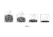
- FIG. 5 is a depiction of the stages of solvent evaporation during solution casting.
- FIG. 6 is a plot showing how birefringence varies with the degree of substitution of Ar-BESs with nitro groups.
- FIG. 7 is a depiction of the framework for calculating the buttressing factor for poly(2-vinyl naphthalene).
- FIG. 8 is a depiction of the framework for calculating the buttressing factor for poly(vinylpyrene).
- FIG. 9 is a depiction of the framework for calculating the buttressing factor for poly[2,5-bis(p-alkoxyphenyl)styrene].
- the optical compensation films of the invention may be aligned anisotropically such that the net optical axis of a rod-like OASU (in the rod-direction) is out-of-plane (where out-of-plane includes but is not limited to optical axes that are perpendicular to the plane), and the net optical axis of a disk-like or Ar-BES OASU (in the disk normal direction) is in-plane (where in-plane includes but is not limited to optical axes that are parallel to the plane).
- the optical compensation films of the invention may be used as part of a liquid crystal display (LCD) device, particularly an in-plane switching (IPS) LCD.
- the LCD may be used in electronic devices with display screens including, but not limited to, televisions, computers, cell phone, clocks, microwaves and calculators.
- the polymer film with high positive birefringence has a moiety containing a light stable OASU in the polymer backbone.
- the OASU may be attached directly to the polymer backbone through one covalent bond so the moiety has the general formula:
- R 1 , R 2 , and R 3 are each independently hydrogen atoms, alkyl groups, substituted alkyl groups, or halogens, and OASU is an optically anisotropic sub-unit.
- the OASU may also be attached directly to the polymer backbone through two independent covalent bonds so the moiety has the general formula:
- R 1 , R 2 , and R 3 are each independently hydrogen atoms, alkyl groups, substituted alkyl groups, or halogens, and OASU is an optically anisotropic sub-unit.
- the covalent bond provides a direct connection between the OASU and the polymer backbone that other atoms are not positioned along the covalent bond, which would make the connection between the OASU and the polymer backbone indirect.
- the polymer film may be a homopolymer or a copolymer.
- the copolymer may have one or more moieties containing an OASU attached directly to the polymer backbone through at least one covalent bond.
- the description of the invention applies to any OASU-containing homopolymer or copolymer with any combination of moieties.
- the term “polymer” refers to homopolymers and copolymers.
- the OASU may be disk-like, rod like (mesogen), or aromatic rings (Ar) substituted with birefringence enhancing substituents (BES).
- the OASU is oriented perpendicular to the polymer backbone, and the value of the positive birefringence of the polymer film increases with increasing perpendicularity of the OASUs.
- the polymer solutions may advantageously form an out-of-plane anisotropic alignment upon solvent evaporation and solution film casting without being subject to heat treatment, photo irradiation, or a stretching process (although one or a combination of these processes may be used to further entrance birefringence).
- the resulting buttressed polymer films are stable at ambient conditions, have high positive birefringence and may be inexpensive to produce.
- Positive birefringence is defined as n z >(n x +n y )/2, wherein n x and n y represent in-plan refractive indexes, and n z represents the thickness-direction refractive index of the film.
- each polymer and the optical compensation films made therefrom each has positive birefringence greater than 0.002 throughout the wavelength range of 400 nm ⁇ 800 nm without being subject to heat treatment, photo irradiation, or stretching. However, in certain embodiments these processes may be used to further enhance positive birefringence.
- the compensation films may have birefringence greater than 0.005, 0.01, 0.02 or 0.03 throughout the wavelength range of 400 nm ⁇ 800 nm.
- Birefringence ( ⁇ n) may be measured by determining the birefringence of a film over a wavelength range of about 300 nm to about 800 nm at different increments.
- birefringence of a film may be measured at 633 nm as is customary in the art.
- Reference to ⁇ n at 633 nm is customary because birefringence at wavelengths ⁇ 633 nm is generally higher than birefringence at 633 nm, and birefringence at wavelengths>633 nm is generally the same as or slightly lower than birefringence at 633 nm.
- birefringence at 633 nm is understood in the art as indicating that birefringence throughout 300 nm ⁇ 800 nm is greater than or approximately the same as the birefringence at 633 nm.
- the OASU is a disk.
- the disk may be attached directly to the polymer backbone through one covalent bond so the moiety has the general formula:
- R 1 , R 2 , and R 3 are each independently hydrogen atoms, alkyl groups, substituted alkyl groups, or halogens.
- the disk may also be attached directly to the polymer backbone through two independent covalent bonds.
- the covalent bond may be a carbon-carbon or carbon-nitrogen bond.
- disks may be attached to the polymer backbone via a carbon or nitrogen atoms, such as the carbon atom on a benzene ring or the nitrogen atom on an imide or lactam.
- the disk-containing polymer has a positive birefringence greater than 0.002 throughout the wavelength range of 400 nm ⁇ 800 nm without being subject to heat treatment, photo irradiation, or stretching.
- the disk-containing polymer film may be made by solution casting, and may form an out-of-plane anisotropic alignment upon solvent evaporation.
- the positive birefringence is greater than about 0.005 throughout the wavelength range of 400 nm ⁇ 800 nm.
- the polymer film may be a homopolymer or copolymer with one or more moieties containing a disk attached directly to the polymer backbone through at least one covalent bond.
- the copolymer may have a moiety with the general structure in the polymer backbone:
- R 1 , R 2 , R 3 , R 4 , R 5 , and R 7 are each independently hydrogen atoms, alkyl groups, substituted alkyl groups, or halogens; wherein R 6 is a hydrogen atom, alkyl group, substituted alkyl group, halogen, ester, amide, ketone, ether, cyano, phenyl, epoxy, urethane, urea, or optically anisotropic subunit (OASU) attached directly to the backbone of a residue of an ethylenically unsaturated monomer.
- R 6 is a different disk.
- R 6 is a benzene ring. The disk may also be attached to a copolymer backbone by two covalent bonds.
- the disk is usually a size greater than a benzene ring.
- the disk is usually bulky.
- the disk group has a fused ring structure.
- the “fused ring” structure may be understood to have two or more individual rings that are connected by sharing at least one of their sides.
- Each individual ring in the fused ring may be substituted or unsubstituted and is preferably a six- or five-membered ring, which may be all-carbon or heterocyclic.
- Individual rings in a fused ring may be aromatic or aliphatic.
- Preferred individual rings in a fused ring include, but are not limited to, aromatic rings and substituted aromatic rings, lactam ring and rings based on aromatic imide such as phthalimide and substituted phthalimide.
- the disk group is stable at ambient conditions and thus suitable for use in an optical compensation film for an LCD.
- disk groups include, but are not limited to, naphthalene, anthracene, phenanthrene, naphthacene, pyrene, pentacene, phthalimide, and the like as shown in the following chemical structures:
- polymer compositions comprising moieties with disk groups may be prepared by polymerization of a disk-containing monomer having a vinyl group attached directly to either a carbon or a nitrogen atom on the fused ring.
- disk-containing monomers with polymerizable vinyl groups include, but are not limited to, the following compounds:
- Polymer compositions comprising moieties with disk groups may also be prepared by copolymerization of a disk-containing monomer with one or more ethylenically unsaturated monomers.
- ethylenically unsaturated monomers that may be used to copolymerize with disk-containing monomers include, but are not limited to, one or more of methyl acrylate, methyl methacrylate, ethyl acrylate, ethyl methacrylate, butyl acrylate, butyl methacrylate, isobutyl acrylate, isobutyl methacrylate, ethylhexyl acrylate, 2-ethylhexyl methacrylate, 2-ethylhexyl acrylate, isoprene, octyl acrylate, octyl methacrylate, iso-octyl acrylate, trimethyolpropyl
- Polymerization may be carried out by a method known in the art such as bulk, solution, emulsion, or suspension polymerization.
- the reaction may be free radical, cationic, anionic, zwitterionic, Ziegler-Natta, or atom transfer radical type of polymerization.
- Emulsion polymerization is a preferred method of polymerization when a particularly high molecular weight is desirable. A high molecular weight polymer may lead to better film quality and higher positive birefringence.
- Solution film casting may be done with disk containing polymer, a polymer solution comprising a blend of disk-containing polymer with other polymers, or a copolymer of disk-containing monomer with other monomers, the latter two being advantageous because they may improve film quality and lower cost.
- Polymer solutions may further contain other ingredients such as other polymers or additives.
- the disk-containing polymers may be soluble in, for example, toluene, methyl isobutyl ketone (MIBK), methyl ethyl ketone (MEK), cyclopentanone, N,N-dimethylformamide, or mixtures thereof.
- MIBK methyl isobutyl ketone
- MEK methyl ethyl ketone
- cyclopentanone N,N-dimethylformamide, or mixtures thereof.
- Preferred solvents are toluene and MIBK.
- the OASU is an aromatic ring (Ar) substituted with birefringence enhancing substituents (BES).
- BES could also be substituents on disk or mesogen OASUs.
- the Ar-BES may also be a fused aromatic ring substituted with BES.
- the Ar-BES may be attached directly to the polymer backbone through one covalent bond so the moiety has the general formula:
- R 1 , R 2 , and R 3 are each independently hydrogen atoms, alkyl groups, substituted alkyl groups, or halogens.
- the Ar-BES may also be attached directly to the polymer backbone through two independent covalent bonds.
- the degree of substitution of the aromatic ring with BES is at least 0.1, but it may also be higher.
- the covalent bond may be a carbon-carbon or carbon-nitrogen bond.
- the Ar-BES containing polymer has a positive birefringence greater than 0.002 throughout the wavelength range of 400 nm ⁇ 800 nm without being subject to heat treatment, photo irradiation, or stretching.
- the Ar-BES-containing polymer film may be made by solution casting, and may form an out-of-plane anisotropic alignment upon solvent evaporation.
- the Ar-BES preferrably has a positive birefringence greater than 0.005, and more preferrably has a positive birefringence greater than 0.01 throughout the wavelength range of 400 nm ⁇ 800 nm.
- the polymer film may be a homopolymer or copolymer with one or more moieties containing an Ar-BES attached directly to the polymer backbone through one covalent bond.
- the copolymer may have a moiety with the general structure in the polymer backbone:
- R 1 , R 2 , R 3 , R 4 , R 5 , and R 7 are each independently hydrogen atoms, alkyl groups, substituted alkyl groups, or halogens; wherein R 6 is a hydrogen atom, alkyl group, substituted alkyl group, halogen, ester, amide, ketone, ether, cyano, phenyl, epoxy, urethane, urea, or optically anisotropic subunit (OASU) attached directly to the backbone of the residue of an ethylenically unsaturated monomer.
- R 6 is a different Ar-BES.
- R 6 is a benzene ring.
- the DS of BES is directly related to the polymer's birefringence. Thus, ⁇ n may be manipulated by varying the DS. The solubility of the polymer can also dependent on the DS and be optimized accordingly. The DS can be readily manipulated by one of ordinary skill in the art, for example, by adjusting the starting amounts of BES.
- the Ar-BES-containing polymer is a poly(vinylaromatic), i.e. a polymer resulting from polymerization of the vinyl group on an aromatic ring.
- the poly(vinylaromatic) also has at least one BES.
- Poly(vinylaromatic) with BES advantageously exhibits exceptionally high birefringence values, is soluble in a variety of organic solvents, and may be used to prepare an optical compensation film by solution casting onto a substrate.
- the solubility and birefringence of poly(vinyl aromatics) of the invention can be controlled by incorporating certain BESs and by adjusting their degree of substitutions (DSs) of the aromatic rings of the polymers.
- an LCD device typically contains multi-layers of materials having different solubility in a variety of solvents and a layer can only be coated with a polymer solution that does not dissolve this specific layer.
- the ability to control the solubility and birefringence of a polymer allows the optical film of the present invention to be cast on a specific layer (or substrate) for LCD fabrication to achieve the desirable order of the layers in the device.
- aromatic groups include, but are not limited to, benzene, biphenyl, naphthalene, anthracene, phenanthrene, naphthacene, pyrene, pentacene, triphenyl, and the like.
- the aromatic ring is benzene, biphenyl or naphthalene. Most preferably, the aromatic ring is benzene.
- BES is a group that in general is bulky and/or capable of increasing the polarizability of the disk groups' aromatic ring on poly(vinyl aromatic).
- a polymer may contain different BES groups on different aromatic rings within the same polymer molecule or different BES groups on the same aromatic ring.
- Representatives and illustrative examples of BES include, but are not limited to, NO 2 , Br, I, CN, and phenyl.
- BES substituents are NO 2 , Br, I, and CN.
- BES is NO 2 or Br.
- BES may be attached to an aromatic ring such as benzene at any available position including the positions that are para, ortho or meta to the ethylene moiety.
- a polymer composition may also have BESs that are in different positions on different aromatic rings.
- the BES is para to the ethylene moiety.
- BES may also be mostly at the para position with some BES at the ortho and/or meta positions.
- polymer compositions of BES-substituted aromatic polymers include, but are not limited to, poly(nitrostyrene), poly(bromostyrene), substituted poly(nitrostyrene), substituted poly(bromostyrene), copolymers of nitrostyrene or bromostyrene, and copolymer of substituted nitrostyrene or bromostyrene.
- the polymer composition is poly(nitrostyrene), poly(bromostyrene), a copolymer thereof, or a mixture thereof.
- Poly(nitrostyrene), poly(bromostyrene) and copolymers thereof may be substituted with one or more nitro or bromo BESs, respectively.
- the degree of substitution for bromo or nitro BES is preferrably at least 0.5 and more preferrably at least 0.7. However, the degree of substitution may also be higher or lower in the range 0 ⁇ DS ⁇ 1. Also, DS may be greater than 1.
- the nitro or bromo substituent may be attached to the benzene ring at any available position including the positions that are para, ortho or meta to the ethylene moiety. In a preferred embodiment, the nitro or bromo BES is para to the ethylene moiety.
- preferred polymers include poly(4-nitrostyrene), poly(4-nitrostyrene-co-styrene), poly(4-bromostyrene) and poly(4-bromostyrene-co-styrene).
- preferred polymers are prepared from 4-nitro- or 4-bromostyrene monomers, the nitro or bromo groups, respectively, will always be at the para position.
- poly(nitrostyrene) may be prepared by nitration of polystyrene in the presence of a mixed acid of HNO 3 and H 2 SO 4 as disclosed in Philippides, A., et al., Polymer (1993), 34(16), 3509-13; Fernandez, M. J., et al., Polymer Degradation and Stability (1998), 60(2-3), 257-263; Cowie, J. M. G., et al., European Polymer Journal (1992), 28(2), 145-8; and Al-Najjar, Mohammed M, et al., Polymer Engineering and Science (1996), 36(16), 2083-2087.
- Nitration of polystyrene can be carried out in the presence of an organic solvent such as nitrobenzene, 1,2-dichloroethane, 3-nitrotoluene, carbon tetrachloride, chloroform, methylene chloride, carbon disulfide, N,N-dimethylformamide, N,N-dimethylacetamide, N-methylpyrolidone, or a mixture thereof.
- organic solvent such as nitrobenzene, 1,2-dichloroethane, 3-nitrotoluene, carbon tetrachloride, chloroform, methylene chloride, carbon disulfide, N,N-dimethylformamide, N,N-dimethylacetamide, N-methylpyrolidone, or a mixture thereof.
- Preferred solvents are nitrobenzene and a 3:1 mixture of nitrobenzene and 1,2-dichloroethane.
- Copolymers of nitrostyrene may be prepared by nitration of a copolymer of styrene such as poly(styrene-co-acrylonitrile), poly(styrene-co-4-t-butylstyrene), and poly(styrene-co-methyl methacrylate). They can also be prepared by copolymerization of nitrostyrene with other ethylenically unsaturated monomers such as methyl methacrylate, acrylonitrile, 4-t-butylstyrene, 4-methylstyrene, butyl acrylate, and acrylic acid.
- Poly(nitrostyrene) can also be prepared by polymerization of nitrostyrene monomer as disclosed in Philippides, A. et al., Polymer (1994), 35(8), 1759-63; and Jonquieres, A. et al., Polymer Bulletin ( Berlin ), (1994), 33(4), 389-95.
- Trifluoroacetic anhydride and trifluoroacetic acid may be used with nitric acid as the nitration agent.
- Inorganic nitrate salts such as NH 4 NO 3 , NaNO 3 , KNO 3 , and AgNO 3 may also be used with trifluoroacetic anhydride as the nitration agent as disclosed in Grivello, J. V., J. Org. Chem . (1981), 46, 3056-3060.
- the poly(nitrostyrene) polymers prepared in this invention are soluble in toluene, methyl isobutyl ketone (MIBK), methyl ethyl ketone (MEK), cyclopentanone, N,N-dimethylformamide or a mixture thereof depending on the degree of substitution of the nitro group.
- Preferred solvents for film casting poly(nitrostyrene) are toluene and MIBK or a mixture thereof.
- poly(bromostyrene) may be prepared by bromination of polystyrene in the presence of bromine and a Lewis acid catalyst such as AlCl 3 , FeCl 3 , AlBr 3 , FeBr 3 , SbCl 5 , ZrCl 4 , Sb 2 O 3 , and the like, as disclosed in U.S. Pat. Nos. 5,677,390 and 5,532,322, which are incorporated by reference in their entirety. It may also be prepared by reaction of polystyrene with n-butyllithium-TMEDA complex followed by bromine quenching as disclosed in Farrall, M. J. and Frechet, M. J., Macromolecules , Vol.
- poly(bromostyrene) may also be prepared by polymerization of bromostyrene monomer as described in Farrall, M. J. and Frechet, M. J., Macromolecules , Vol. 12; p. 426, (1979).
- copolymers of bromostyrene may also be prepared as described previously for poly(nitrostyrene).
- Bromination of polystyrene can be carried out in the presence of an organic solvent such as, for example, 1,2-dichloroethane, nitrobenzene, 3-nitrotoluene, carbon tetrachloride, chloroform, methylene chloride, carbon disulfide, N,N-dimethylformamide, N,N-dimethylacetamide, N-methylpyrrolidone, or a mixture thereof.
- organic solvent such as, for example, 1,2-dichloroethane, nitrobenzene, 3-nitrotoluene, carbon tetrachloride, chloroform, methylene chloride, carbon disulfide, N,N-dimethylformamide, N,N-dimethylacetamide, N-methylpyrrolidone, or a mixture thereof.
- Preferred solvents are 1,2-dichloroethane, carbon tetrachloride, and chloroform.
- the poly(bromostyrene) polymers prepared in this invention are soluble in toluene as well as in cyclopentanone even with high degrees of substitution. This is particularly useful for coating a TAC substrate since toluene will not have a detrimental effect on the TAC film.
- Polymer compositions comprising moieties with Ar-BES may also be prepared by copolymerization of an Ar-BES-containing monomer with one or more ethylenically unsaturated monomers.
- ethylenically unsaturated monomers that may be used to copolymerize with disk-containing monomers include, but are not limited to, one or more of methyl acrylate, methyl methacrylate, ethyl acrylate, ethyl methacrylate, butyl acrylate, butyl methacrylate, isobutyl acrylate, isobutyl methacrylate, ethylhexyl acrylate, 2-ethylhexyl methacrylate, 2-ethylhexyl acrylate, isoprene, octyl acrylate, octyl methacrylate, iso-octyl acrylate, trimethyo
- Polymerization may be carried out by a method known in the art such as bulk, solution, emulsion, or suspension polymerization.
- the reaction may be free radical, cationic, anionic, zwitterionic, Ziegler-Natta, or atom transfer radical type of polymerization.
- Emulsion polymerization is a preferred method of polymerization when a particularly high polymer molecular weight is desirable. A high molecular weight polymer may lead to better film quality and higher positive birefringence.
- Solution film casting may be done with Ar-BES containing polymer, a polymer solution comprising a blend of Ar-BES-containing polymer with other polymers, or a copolymer of Ar-BES containing monomer with other monomers, the latter two being advantageous because they may improve film quality and lower cost.
- Polymer solutions may further contain other ingredients such as other polymers or additives.
- the Ar-BES-containing polymers may be soluble in, for example, toluene, methyl isobutyl ketone (MIBK), methyl ethyl ketone (MEK), cyclopentanone, N,N-dimethylformamide, or mixtures thereof.
- Preferred solvents are toluene and MIBK.
- the OASU is rod-like.
- the rod-like structure is a mesogen.
- the mesogen may be attached directly to the polymer backbone through one covalent bond (without a spacer) so the moiety has the general formula:
- R 1 , R 2 , and R 3 are each independently hydrogen atoms, alkyl groups, substituted alkyl groups, or halogens.
- the mesogen may also be attached directly to the polymer backbone through two independent covalent bonds.
- the covalent bond may be a carbon-carbon or carbon-nitrogen bond.
- the mesogen is attached to the polymer backbone preferably at the gravity center of the mesogen or a nearby position, but may also be attached at an end or off-center position.
- the mesogen-containing polymer has a positive birefringence greater than 0.002 throughout the wavelength range of 400 nm ⁇ 800 nm without being subject to heat treatment, photo irradiation, or stretching.
- the mesogen-containing polymer film may be made by solution casting and may form an out-of-plane anisotropic alignment upon solvent evaporation.
- the positive birefringence is greater than 0.005, greater than 0.01, greater than 0.02 or greater than 0.03 throughout the wavelength range of 400 nm ⁇ 800 nm.
- the mesogen-containing polymers in the present invention are commonly referred to as mesogen jacketed polymers (MJPs).
- MJPs according to the invention include conventional mesogen-jacketed liquid crystalline polymers (MJLCPs) as well as polymers that are jacketed by a non-liquid crystalline rod-like group.
- the polymer film may be a homopolymer or copolymer with one or more moieties containing a mesogen attached directly to the polymer backbone through at least one covalent bond.
- the copolymer may have a moiety with the general structure in the polymer backbone:
- R 1 , R 2 , R 3 , R 4 , R 5 , and R 7 are each independently hydrogen atoms, alkyl groups, substituted alkyl groups, or halogens; wherein R 6 is a hydrogen atom, alkyl group, substituted alkyl group, halogen, ester, amide, ketone, ether, cyano, phenyl, epoxy, urethane, urea, or optically anisotropic subunit (OASU) attached directly to the backbone of the residue of an ethylenically unsaturated monomer.
- R 6 is a different mesogen.
- the mesogen may also be attached to a copolymer backbone by two covalent bonds.
- mesogen-jacked polymers have no or very short spacers between the polymer backbones and the rod-like mesogenic units. See Zhao, Y. F., et al. Macromolecules, 2006, 39, p. 948. Thus, MJPs have a strong interaction between the main chains and the bulky side groups. As a result, unlike the conventional side-chain LCPs whose backbones usually take a random-coil chain conformation, MJPs are somewhat rigid and exhibit some characteristics of main-chain LCPs.
- MJPs having no spacers between the backbones and the rod-like mesogenic side groups are capable of forming out-of-plane anisotropically aligned films without being subject to either heat treatment or photo irradiation.
- An embodiment of the invention includes preparing such films by solution casting. Upon solvent evaporation at an ambient temperature, the resulting films exhibit exceptionally high positive birefringence.
- MJPs of the invention are soluble in a variety of organic solvents.
- Mesogens of the invention may have the general formula: R 1 -(A 1 -Z 1 ) m -A 2 -(Z 2 -A 3 ) n -R 2 wherein, A 1 , A 2 , and A 3 are independently either aromatic or cycloaliphatic rings.
- the rings may be all carbons or heterocyclic and may be unsubstituted or mono- or poly-substituted with halogen, cyano or nitro, or alkyl, alkoxy, or alkanoyl groups having 1 to 8 carbon atoms.
- Z 1 , Z 2 , and Z 3 are each independently —COO—, —OOC—, —CO—, —CONH—, —NHCO—, —CH ⁇ CH—, —C ⁇ C—, —CH ⁇ N—, —N ⁇ CH—, —N ⁇ N—, —O—, —S—, or a single bond.
- R 1 and R 2 are each independently halogen, cyano, or nitro groups, or alkyl, alkoxy, or alkanoyl groups having 1 to 25 carbon atoms, or has one of the meanings given for —(Z 2 -A 3 ).
- m is 0, 1, or 2; n is 1 or 2.
- m is 1 or 2; n is 1 or 2; A 2 is 1,4-phenylene; and the mesogen is attached to the polymer backbone through A 2 . More preferably, m is 2; n is 2; A 2 is 1,4-phenylene; and the mesogen is attached to the polymer backbone through A 2 .
- aromatic rings in a mesogen include, but are not limited to:
- cycloaliphatic rings in a mesogen include, but are not limited to:
- mesogens that may be attached to the polymer backbone through one covalent bond include, but are not limited to:
- Such mesogens may be attached to the polymer backbone via a carbon atom on a benzene ring or a nitrogen atom on a triazole.
- the mesogen is attached to the polymer backbone via a carbon atom on the center 1,4-phenylene or a nitrogen atom on the heterocyclic ring.
- Representatives and illustrative examples of preferred polymer moieties with mesogens having m is 1 or 2, n is 1 or 2, A 2 is 1,4-phenylene, and the mesogen is attached to the polymer backbone through A 2 include, but are not limited to:
- Representatives and illustrative examples of preferred polymer moieties with mesogens having m is 2, n is 2, A 2 is 1,4-phenylene, and the mesogen is attached to the polymer backbone through A 2 include, but are not limited to:
- R 1 , R 2 , and R 3 are hydrogen atoms, alkyl groups, or halogens.
- an optical film is solution cast from polymer compositions with one or more moieties of a mesogen having m is 2, n is 2, A 2 is 1,4-phenylene, and being attached to the polymer backbone through A 2
- This mesogen-jacketed polymer film has an absorption maxima between the wavelengths of about 300 nm and about 350 nm and a positive birefringence greater than about 0.015 throughout 400 nm ⁇ 800 nm.
- Representative and illustrative examples of such polymer moieties include, but are not limited to:
- R 1 , R 2 , and R 3 are hydrogen atoms, alkyl groups, or halogens.
- MJPs of the invention may be prepared by polymerization of a mesogen monomer having a vinyl group attached to one of its rings, preferably an aromatic ring such as benzene.
- the polymerization may be carried out by a method known in the art such as bulk, solution, emulsion, or suspension polymerization.
- the reaction may be free radical, cationic, anionic, zwitterionic, Ziegler-Natta, or atom transfer radical type of polymerization. See Zhou, Q. F., et al. Macromolecules, 1987, 20, p. 233; Zhang, D., et al., Macromolecules, 1999, 32, p. 5183; Zhang, D., et al., Macromolecule, 1999, 32, p. 4494; and Chen, X., et al., Macromolecules, 2006, 39, p. 517.
- mesogen monomers with polymerizable vinyl groups suitable for the invention include, but are not limited to:
- preferred mesogen monomers with polymerizable vinyl groups suitable for the invention include, but are not limited to:
- Polymers with these moieties have a positive birefringence greater than about 0.02 throughout the wavelength range of 400 nm ⁇ 800 nm.
- MJPs of the present invention may also be prepared by copolymerization of a mesogen monomer having one vinyl group with one or more ethylenically unsaturated monomers.
- ethylenically unsaturated monomers that may be used for copolymerization with mesogen-containing monomers include, but are not limited to, one or more of methyl acrylate, methyl methacrylate, ethyl acrylate, ethyl methacrylate, butyl acrylate, butyl methacrylate, isobutyl acrylate, isobutyl methacrylate, ethylhexyl acrylate, 2-ethylhexyl methacrylate, 2-ethylhexyl acrylate, isoprene, octyl acrylate, octyl methacrylate, iso-octyl acrylate, iso-octyl methacrylate, iso-oc
- MJP may also be prepared by first synthesizing a functionalized polymer and then subsequently reacting the polymer with a small molecule to obtain the desired mesogen structure.
- Solution film casting may be done with MJPs, a polymer solution comprising a blend of MJPs with other polymers, or a copolymer of MJPs, the latter two being advantageous because they may improve film quality and lower cost.
- Polymer solutions may further contain other ingredients such as other polymers or additives.
- MJPs of the invention are soluble in toluene, methyl isobutyl ketone (MIBK), methyl ethyl ketone (MEK), cyclopentanone, N,N-dimethylformamide or a mixture thereof depending on the structures of the mesogens.
- Preferred solvents are toluene and MIBK.
- Optical films can be cast onto a substrate from the resulting polymer solutions by a method known in the art such as, for example, spin coating, as described above.
- the OASU is attached directly to the polymer backbone through two independent covalent bonds so the moiety has the general formula:
- R 1 , R 2 , and R 3 are each independently hydrogen atoms, alkyl groups, substituted alkyl groups, or halogens, and OASU is an optically anisotropic sub-unit.
- polymer moieties having OASU attached directly to the polymer backbone through two independent covalent bonds include, but are not limited to:
- Another example embodiment of the invention includes a method for controlling the birefringence of an optical compensation film by selecting a polymer that adheres to parameters that have been discovered to enhance birefringence as disclosed herein.
- Birefringence of a polymer film with positive birefringence may be controlled by controlling the orientation of optically anisotropic subunits (OASUs), which are the molecular units that give a compensation film its birefringent properties.
- OASUs optically anisotropic subunits
- D is still the distance between attaching points of the two closest OASUs, even if the OASUs are not directly adjacent to each other or if other substituents are between the OASUs along the polymer chain.
- the buttressing factor B of a given polymer or copolymer structure may be calculated theoretically based on values of bond lengths and the corresponding distances between atoms or substituents. As will be understood by one of ordinary skill in the art, bond lengths may be calculated by techniques such as x-ray crystallography, X-ray-absorption fine structure, NMR spectroscopy and electron diffraction.
- R and D values may be understood by reference to an exemplary polymer, polystyrene, which is explained in FIGS. 1-2 and the following example.
- D is the distance between the attaching points of two OASUs to the polymer backbone when the polymer is in the extended chain conformation, as depicted in exemplary FIG. 1 a .
- D is the straight line distance between the attaching points of neighboring OASUs rather than the entire distance along the polymer backbone between the attaching points.
- D may be calculated by drawing a framework around an OASU-containing moiety and using known bond lengths and bond angles.
- FIG. 2 a shows the point on the polymer backbone at which the OASU of reference (the benzene ring) will be attached.
- FIG. 2 b shows a segment of the polymer backbone in the extended chain conformation. For polystyrene, this represents two single carbon-carbon bonds, each having a bond length of 0.154 nm and a bond angle of 109.5°.
- D is approximately 2.51 ⁇ .
- R measures the size of an OASU in the direction perpendicular to its rigid bond to the polymer backbone.
- the OASU is drawn to scale in the plane of the paper according to its actual bond lengths and bond angles.
- R is measured by drawing lines flanking the OASU that are parallel to the covalent spacer bond and parallel to each other and determining the distance between the two outer lines using bond lengths and bond angles. That value is added to the van der waals radii of the left-most and right-most atoms of the OASU. This sum will be the value of R.
- This calculation is illustrated for the exemplary polymer polystyrene in FIG. 2 d - f .
- FIG. 2 d shows the covalent bond from a carbon atom of the polymer backbone to the attaching atom of the OASU. In the case of polystyrene, the attaching atom is also carbon.
- FIG. 2 e shows the structure of benzene attached to the polymer backbone and its known bond lengths and bond angles. All carbon-carbon bond lengths of the benzene ring are 0.14 nm, all bond angles of the benzene ring are 120°, and all carbon-hydrogen bond lengths of the benzene ring are 0.11 nm.
- FIG. 2 f shows the benzene ring with parallel vertical lines drawn at intervals such that calculating the distances of segments of the OASU is possible for each interval.
- bonds 1, 2, 3 and 4 each have an angle of 30° with respect to the horizontal length of the benzene OASU, and thus each segment has a length calculated by bond length ⁇ cos 30°, and R is the sum of these segment lengths plus the van der waals radii of the hydrogen atoms, which are each 0.12 nm.
- R is approximately 6.7 ⁇ .
- Other examples of R calculations are depicted in FIGS.
- the R calculation will be the same as for styrene because the BES at the 4-position does not contribute to the dimension (R) of the Ar-BES and is thus not included in the calculation of R.
- the van der waals radii of the oxygen atoms in FIG. 1 i are the right-most and left-most distances to be included in the R calculation.
- Equation for calculating R may differ for different OASUs because it is dependent on the bond lengths and angles of the OASU.
- OASUs with different atoms or different conformations may use different equations to calculate R, but the equation will be based on the principals described herein.
- the buttressing factor B is greater than about 2.5, the maximum dimension of an OASU is greater than its distance from another OASU in the direction perpendicular to the covalent bond that attaches the OASU to the polymer backbone.
- These optimal parameters cause the polymer backbone to twist into a corkscrew-like conformation such that the OASUs are oriented above and below the buttressed polymer chain, but not on the sides of the buttressed polymer chain, to accommodate the bulky OASUs in a sterically favorable conformation.
- the buttressed polymer chain is unable to unwind due to steric hindrance.
- the buttressing effect also causes the polymer backbone to have an overall linear shape (i.e., viewed from a distance) over a long distance.
- the buttressed polymer is rigidly fixed in the corkscrew-like conformation with OASUs extending above and below at angles that are approximately perpendicular to the overall linear direction of the buttressed polymer chain, as shown in FIG. 3 .
- the buttressing factor for an OASU is greater than about 2.5.
- the OASU is Ar-BES and the buttressing factor may be at least about 2.6. In a more preferred embodiment, the buttressing factor for an OASU is at least about 2.7. In one embodiment, the OASU is a disk or a mesogen and the buttressing factor may be at least about 2.7.
- Polymer chain rigidity can be enhanced by increasing the buttressing factor, i.e. by increasing the dimension and/or decreasing the distance between OASUs.
- the buttressing factor may be increased depending on the desired chain rigidity, which affects the overall birefringence of a compensation film containing the buttressed polymer. Accordingly, it may be desirable to increase the buttressing factor to any higher value of B, such as for example 3, 4, 5, 6, 7, 8, 9, 10, 11, 12 or any increments between.
- higher values of B may also be contemplated depending on the particular application of the compensation film and its desired birefringence.
- the perpendicularity of the OASUs allows the film to have an index of refraction in the direction perpendicular to the film (i.e., along the optical axis of the OASUs) that is higher than the index of refraction in the direction parallel to the film (i.e., along the length of the buttressed polymer's backbone.
- the compensation film satisfies the relation n ⁇ >>n ⁇ . Since the difference between n ⁇ and n ⁇ is great, the birefringence ⁇ n of the compensation film is high.
- High birefringence ⁇ n achieved through selecting a polymer with the buttressing effect is also desirable because it allows the thickness of the compensation film to be thinner since film birefringence and thickness vary inversely.
- the retardation value of an optical compensation film is defined as d ⁇ n, wherein d is the thickness of the film.
- d is the thickness of the film.
- the retardation value of the optical compensation film may preferably be 50 nm to 400 nm.
- ⁇ n OASU is greater than zero for rod-like OASUs because their optical axis is in the rod direction of OASU so n o OASU >n e OASU .
- ⁇ n OASU is less than zero for disk-like OASUs because their optical axis is perpendicular to the plane of the OASU disk so n o OASU ⁇ n e OASU .
- ⁇ is in the range from 0° to 90°, and O OASU is thus in the range from ⁇ 0.5 to 1. Therefore, O OASU may be positive, negative, or zero.
- the invention pertains to positive C plates.
- the rod-like OASU requires a positive order parameter (O OASU >0)
- O S is always negative or zero. Therefore, in the case of non-zero O S , the sign of ⁇ n is determined by the sign of ⁇ n S .
- O S preferably has a large absolute value, which requires a sufficiently large segment size or a sufficiently long persistent length.
- rod-like OASUs For a rod-like OASU, ⁇ n OASU >0 and O S ⁇ 0. Thus, positive C-plates require negative O U-S . O U-S is negative when the rods are perpendicular to the segment direction.
- rod-like OASUs are selected such that the distance between the two attaching points of the neighboring OASUs is shorter than the length of the rod the so that they exhibit the buttressing effect. If the rod-like OASUs are selected according to these parameters, then the rods can no longer rotate freely. Instead, some conformation with rod direction parallel to the main chain direction will be forbidden due to steric hindrance. Further, the main polymer chain will be substantially rigid and linear over a long distance.
- OASU may be attached to the main chain from any position as long as buttressing effect is present.
- OASUs according to the buttressing effect parameters allows birefringence to be manipulated because it generates and enhances the non-zero segment parameter, O U-S .
- the buttressing effect will make some of the OASU's conformations forbidden and thus leads to the preferred orientation of the OASU.
- the buttressing effect is the basic reason for the negative OASU order parameter within a segment O U-S .
- the bigger buttressing factor will have a stronger buttressing effect and make O U-S more negative for rod-like model and more positive for disk-like model.
- An advantage of the invention is that compensation films with high birefringence may be obtained by a simple solution casting process without any other post-processing such as stretching, photopolymerization, etc.
- Solution casting without post-processing may significantly reduce the cost of film fabrication and help eliminate errors caused by the complexity of post-processing.
- post-casting processing such as uniaxially or biaxially stretching or photopolymerization, may be used to further enhance the compensation film's high positive birefringence.
- the order parameter of a polymer segment, O S is mainly determined by the conditions of solution casting, such as temperature, evaporation rate, and concentration.
- solvents may be used for solution casting the optical compensation films of the invention including, but not limited to, chloroform, dichloromethane, dichloroethane, benzene, chlorobenzene, xylene, N,N-dimethylformamide, N,N-dimethylacetamide, N-methyl-2-pyrrolidone, pyridine, dimethylsulfoxide, acetonitrile, cyclohexanone, methyl amyl ketone, ethyl acetate, ethylene glycol monobutyl ether, and the like.
- Preferred solvents include toluene, methyl isobutyl ketone (MIBK), methyl ethyl ketone (MEK), and cyclopentanone.
- Optical films may be cast onto a substrate from polymer solutions by a method known in the art such as, for example, spin coating, spray coating, roll coating, curtain coating, or dip coating.
- Substrates are known in the art, and include TAC (triacetylcellulose), polyester, polyvinyl alcohol, cellulose ester, polycarbonate, polyacrylate, polyolefin, polyurethane, polystyrene, glass, and other materials commonly used in an LCD device.
- the solution-cast compensation film may be removed from the substrate after drying to yield a free-standing film.
- the already high birefringence of the film may optionally be further enhanced by uniaxial or biaxial stretching.
- the free-standing film may also be laminated onto a substrate.
- Polymer chains have a random orientation in the homogeneous solution.
- the conformation of polymer chains in solution is generally a random coil, unless the polymer backbone is rigid while molecular weight is low, which may have a rod-like shape.
- polymer chains in solution resemble loosely threaded-balls filled with solvent. After solution casting, the balls deflate during solvent evaporation and collapse into flatter “pancake” shapes. This process is continuous as long as solvent evaporation continues. As a result, the order parameter of the polymer segments, O s , becomes more and more negative when the polymer collapses. Polymer chain segments become aligned parallel to the substrate surface. However, other factors such as competition between the evaporation rate of the solvent and the relaxation process of the polymer chains determine whether or not this aligned segment orientation is maintained.
- solvent evaporation generally follows a free relaxation model.
- the order parameter of the polymer segments is zero.
- the system fluctuates between the collapsed ball shape and round ball shape.
- the polymer's glass transition temperature is lower than the environment temperature so that polymer chains relax fast enough to compete with the collapse.
- the ball-shape becomes smaller and the solution on the substrate becomes increasingly concentrated.
- the glass transition temperature of the polymer chains is close to the environmental temperature, and polymer relaxations become too slow to follow the solvent's evaporation or the collapsing procedure.
- the polymer solution reaches the “frozen point” and the system follows the frozen model.
- the final order parameter of the polymer segments after solution casting is determined by the frozen point, v f .
- v f may be determined by many factors including, but not limited to, evaporation rate of the solvent, environmental temperature, solubility of the polymer in the solvent and the chemical structure of the polymer, which affects relaxation.
- the evaporation rate is preferably slow enough to ensure that the ball shape collapses but fast enough to ensure that the relaxation rate is slower at more dilute concentrations.
- evaporation rate may be adjusted by adjusting environmental temperature and pressure.
- the relaxation rate depends on the chemical structure of polymer and the film casting temperature. Polymers with rigid segments may freeze easily at the environmental temperature.
- Polymer samples were first dissolved in suitable solvents and were solution cast onto a piece of cleaned glass with the size of 1 ⁇ 1.5 inches.
- the thickness of the polymer film was controlled in the range of 15 to 20 ⁇ m by adjusting the content of solid in the solution. After the solvent evaporated, the polymer film was peeled off the glass to obtain a piece of free-standing film. Birefringence of the free-standing polymer films was measured by a prism coupler (Model 2010), from Metricon Corp. at 633 nm.
- 2-Vinylnaphthalene (2.00 g) was charged to a Schlenk tube.
- the tube was stoppered, evacuated by pulling vacuum, and then filled with argon gas.
- the tube was evacuated and then refilled with argon four more times. While under a positive pressure of argon, the tube was immersed into an oil bath maintained at 70° C. for 24 hours. After cooling to room temperature, the solid plug of material was dissolved in tetrahydrofuran (THF).
- THF tetrahydrofuran
- the solution was added in a dropwise manner into 500 mL of rapidly stirring methanol, causing the polymer to precipitate.
- the precipitated polymer was collected by filtration and dried by pulling air through the material on a filter pad.
- the polymer was then dissolved in fresh THF and reprecipitated by dropwise addition into rapidly stirring methanol. After collection by filtration and drying, the resulting polymer was found to have MW of 127,000 g/mol and a Tg of 139° C.
- a film cast from cyclopentanone (Cp) showed a positive birefringence of 0.0040 at 633 nm.
- the precipitated polymer was collected by filtration and dried by pulling air through the material on a filter pad.
- the polymer was then dissolved in tetrahydrofuran and reprecipitated by dropwise addition into rapidly stirring methanol. After collection by filtration and drying, the resulting polymer was found to have MW of 251,000 g/mol and a Tg of 148° C.
- a film cast from cyclopentanone showed a positive birefringence of 0.0073 at 633 nm.
- the resulting polymer was found to have MW of 550,000 g/mol and a Tg of 146° C.
- a film cast from cyclopentanone showed a positive birefringence of 0.0062 at 633 nm.
- 1-Vinylpyrene (2.0 g) was charged to a Schlenk tube.
- the tube was stoppered, evacuated by pulling vacuum, and then filled with argon gas.
- the tube was evacuated and then refilled with argon four more times. While under a positive pressure of argon, the tube was immersed into an oil bath maintained at 100° C. for 24 hours. After cooling to room temperature, the solid plug of material was dissolved in tetrahydrofuran (THF). The solution was added in a dropwise manner into rapidly stirring ethanol, causing the polymer to precipitate. The precipitated polymer was collected by filtration and dried by pulling air through the material on a filter pad.
- THF tetrahydrofuran
- the polymer was then dissolved in fresh THF and reprecipitated by dropwise addition into rapidly stirring ethanol. After collection by filtration and drying, the resulting polymer was found to have MW of 72,600 g/mol and a Tg of 254° C. A film cast from cyclopentanone showed a positive birefringence of 0.0051 at 633 nm.
- copolymers were prepared by charging various mole ratios of styrene (S) with either N-vinyl phthalimide (VPI) or N-vinyl-4,5-dichlorophthalimide (VDCPI), Films were then cast from NMP and their birefringence measured as listed in the table below. It should be noted, however, the mole ratios of the resulting polymers could vary due to low yields (about 30%).
- the solid was dissolved in N,N-dimethylformamide (DMF) and re-precipitated into methanol.
- the resulting heterogeneous mixture was stirred for two hours, filtered, washed repeatedly with methanol, and dried under vacuum to give a slightly yellowish fibrous powder.
- the yield was generally >95%.
- Product 1 was soluble in DMF but not in Cp, while the others were soluble in Cp.
- Films of 2, 3, and 4 were cast respectively from their Cp solutions by spreading the solutions on glass slides and allowing to dry at room temperature in air to form thin films (about 15-20 ⁇ m).
- a film of product 1 was cast from DMF and dried under vacuum due to the hygroscopic character of DMF.
- % N of the polymer was determined by elemental analysis, from which the degree of substitution (DS) of the nitro group was calculated.
- Example 8 Using the same method in Example 8, a series of poly(nitrostyrenes) having various degrees of substitution (DS) were prepared by adjusting the nitro/styrene equivalent ratio. Their solubility and birefringence were then determined; the results are plotted in FIG. 6 . As illustrated in FIG. 6 , the solubility of the poly(nitrostyrene) decreases with increased DS.
- FIG. 6 also shows that the birefringence of the poly(nitrostyrene) increases with increased degree of nitration.
- a copolymer was prepared by nitration of poly(styrene-co-acrylonitrile) (75% styrene, MW 165K; Aldrich) using the same method as in Example 8 with an equivalent ratio of nitro/styrene, 3/1.
- the resulting polymer had Tg of 151° C., % N, 5.84 (DS 0.62) (excluding CN group), and was soluble in cyclopentanone (Cp).
- a film was cast from Cp and showed a positive birefringence of 0.0089 at 633 nm.
- Polystyrene (5.0 g) (Mw 280,000; Aldrich) was stirred and dissolved in 1,2-dichloroethane (100 g) in a three-neck round-bottom flask equipped with a mechanical stirrer.
- AlCl 3 0.1 g
- bromine (15.4 g)
- the mixture was allowed to react at room temperature under nitrogen for a total of 7 hours.
- the resulting red mixture was precipitated into methanol, filtered, and washed repeatedly with methanol to give a slightly yellowish fibrous powder (7.2 g).
- the product was soluble in toluene or Cp and has a Tg of 134° C., 34% of Br (DS 0.78).
- a film was cast from toluene and measured to have ⁇ n+0.0069 @ 633 nm.
- a copolymer was prepared by bromination of poly(styrene-co-acrylonitrile) (75% styrene, MW 165K; Aldrich) using the same method as in Example 11 with an equivalent ratio of Br/styrene, 2/1.
- the resulting polymer had Tg of 141° C., 26% Br (DS 0.65), and was soluble in MIBK.
- a film cast from MIBK showed a positive birefringence of 0.0024 at 633 nm.
- a poly(bromo-nitrostyrene) was prepared by bromination of a poly(nitrostyrene) having DS 0.47 prepared as in Example 7.
- poly(nitrostyrene) (3.0 g), AlCl 3 (0.1 g), and bromine (4.62 g) (Br/styrene 2/1) were used.
- the mixture was allowed to react for 5 hours to give a slightly yellowish powder (2.5 g); Tg 139° C.; soluble in MIBK or cyclopentanone; film cast from MIBK having ⁇ n+0.0054 @ 633 nm.
- a poly(nitro-bromostyrene) was prepared by nitration of poly(bromostyrene) prepared in Example 11.
- poly(nitrostyrene) (2.50 g), HNO 3 (2.15 g), and H 2 SO 4 (2.50 g) were used.
- the mixture was allowed to react for 5 hours to give a slightly yellowish powder (2.1 g); Tg 144° C.; % N, 1.67; soluble in cyclopentanone.
- a nitro-substituted polymer was prepared by nitration of poly(2-vinylnaphthalene) (Mw 251 K; Tg 148° C.) using the same method as in Example 8 with an equivalent ratio of nitro/styrene, 2/1.
- the reaction was carried out by charging poly(2-vinylnaphthalene) (0.25 g), nitrobenzene (4.5 g), 1,2-dichloroethane (1.5 g), HNO 3 (0.29 g), and H 2 SO 4 (0.34 g) to a 50 ml flask equipped with a magnetic stirrer. The mixture was allowed to react for 22 hours to give a powder (0.33 g).
- the resulting polymer had Tg of 199° C. and % N, 2.17 (DS 0.31) and was soluble in cyclopentanone.
- a film cast from Cp showed a positive birefringence of 0.0088 at 633 nm.
- a nitro-substituted polymer was prepared by nitration of poly(4-vinyl biphenyl) (Mw 396K; Tg 150° C.) by using poly(4-vinyl biphenyl) (0.25 g), nitrobenzene (4.5 g), 1,2-dichloroethane (1.5 g), HNO 3 (0.25 g), and H 2 SO 4 (0.29 g).
- the resulting polymer had Tg of 192° C. and % N, 2.30 (DS 0.37) and was soluble in cyclopentanone.
- a film cast from Cp showed a positive birefringence of 0.0097 at 633 nm.
- a bromo-substituted polymer was prepared by bromination of poly(styrene-co-4-vinyl biphenyl) (Mw 229K) by using poly(styrene-co-4-vinyl biphenyl) (0.5 g), 1,2-dichloroethane (14 g), AlCl 3 (0.04 g), and bromine (1.54 g).
- the resulting polymer had Tg of 161° C., % Br of 35% (DS ⁇ 1) and was soluble in toluene.
- a film cast from Cp showed a positive birefringence of 0.0028 at 633 nm.
- This example illustrates an MIBK-soluble poly(nitrostyrene) with high positive birefringence can be prepared by first reacting polystyrene with t-butylchloride and subsequently reacting with a mixed acid.
- the polymer was then dissolved in fresh THF and reprecipitated by dropwise addition into rapidly stirring methanol. After collection by filtration and drying, the resulting polymer was found to have MW of 396,000 g/mol and a Tg of 150° C. A film cast from cyclopentanone showed a positive birefringence of 0.0071 at 633 nm.
- the resulting solution was slowly poured into 500 mL of rapidly stirring methanol, causing the resulting polymer to precipitate.
- the precipitated polymer was collected by filtration and dried by pulling air through the material on a filter pad.
- the polymer was then dissolved in fresh DMAc and reprecipitated by dropwise addition into rapidly stirring methanol. After collection by filtration and drying, the resulting polymer was found to have MW of 842,000 g/mol and a Tg of 184° C.
- a film cast from cyclopentanone showed a positive birefringence of 0.0103 at 633 nm.
- Polymers 1-5 were synthesized by free-radical solution polymerization and their Tg and birefringence values determined as listed in the following table:
- the following mesogen-jacketed polymers were made by charging the vinyl mesogen monomers, benzoyl peroxide (BPO, 0.1-0.3% mole of monomers) and toluene or chlorobenzene to a polymerization tube containing a Teflon-coated magnetic stirbar.
- BPO benzoyl peroxide
- the reaction mixture was degassed by bubbling argon through for 15 minutes.
- the tube was then sealed and immersed into an oil bath maintained at 80° C. for one day. After cooling the reaction mixture to room temperature, it was slowly poured into rapidly stirring methanol, causing the resulting polymer to precipitate.
- the precipitated polymer was collected by filtration and dried in a vacuum oven.
- R 1 —OCH 2 CH(CH 3 )CH 2 CH 3
- mesogen-jacketed polymers are suitable for the practice of this invention as well.
- the buttressing factor B was calculated for a naphthalene ring OASU.
- the attaching atom of the OASU is the 2-position carbon atom on the naphthalene ring. All of the carbon-carbon bond lengths of the naphthalene ring are 0.14 nm, all bond angles of the naphthalene ring are 120°, and all carbon-hydrogen bond lengths of the naphthalene ring are 0.11 nm as shown in FIG. 7 b .
- This R/D value is bigger than PS and thus lead to a stronger buttressing effect and higher positive birefringence as compared to PS.
- the naphthalene OASU has a bigger ⁇ n OASU than PS, which enhanced the overall ⁇ n.
- the solution cast poly(2-vinyl naphthalene) film showed a positive birefringence of 0.0073 at 633 nm.
- the buttressing factor B was calculated for a pyrene OASU.
- the attaching atom of the OASU is a carbon atom on the pyrene ring. All of the carbon-carbon bond lengths of the pyrene ring are 0.14 nm, all bond angles of the pyrene ring are 120°, and all carbon-hydrogen bond lengths of the pyrene ring are 0.11 nm shown in FIG. 8 b .
- the bond angles of bonds 1, 2, 3, 4, 5, 6 and 7 with respect to the horizontal length of the OASU as shown in FIG. 8 c are all 30°.
- the left-most and right-most atoms are hydrogen atoms and have van der waals radii of 0.12 nm.
- This R/D value is bigger than PS and thus lead to stronger buttressing effect and higher positive birefringence as compared to PS. Also, the pyrene OASU has a bigger ⁇ n OASU than PS, which enhanced the final ⁇ n.
- the solution cast PVPr film showed a positive birefringence of 0.0051 at 633 nm.
- a BES at the 4-position of benzene ring enhanced the birefringence of polystyrene without changing its buttressing effect.
- Polystyrene was substituted at the 4-position with the following BES: Cl, Br, I, CN, NO 2 , and phenyl.
- Each BES-substituted polystyrene had the same buttressing factor (R/D value) as unsubstituted polystyrene but exhibited enhanced birefringence.
- R/D value buttressing factor
- Using the highly polarizable and polar NO 2 group enhanced the birefringence of BES-substituted polystyrene to as high as 0.0209.
- the buttressing factor was calculated for the mesogen OASU depicted above.
- the mesogen OASU has the same backbone structure as polystyrene (PS) and thus D is calculated the same as for PS, yielding 0.25 nm.
- the attaching atom of the OASU is a carbon atom on the middle benzene ring of the mesogen OASU. All of the carbon-carbon bond lengths of the benzene rings are 0.14 nm n, all bond angles of the benzene rings are 120°, the carbon-carbon bond between two benzene rings is 0.15 nm, and all carbon-oxygen bond lengths of the mesogen are 0.14 nm shown in FIG. 9 .
- the length between carbon 1 and carbon 4 of the benzene rings (depicted as lines 2, 4 and 6 in FIG. 9 ) is 0.28 nm.
- the three benzene rings don't lie in the same plane because the OASU may twist on its axis, the benzene rings maintain a linear alignment.
- the 1-, 4-carbon atoms of all three benzene rings lie on that line.
- the bond angles of bonds 1, 3, 5 and 7 and lines 2, 4 and 6 with respect to the horizontal length of the OASU as shown in FIG. 9 are all 30°.
- This R/D value is bigger than PS and thus lead to stronger buttressing effect and higher positive birefringence as compared to PS.
- this mesogen OASU has a bigger ⁇ n OASU than PS, which enhanced the final ⁇ n.
- the solution cast this mesogen jacket polymer film (with R 1 as —OCH 2 CH 2 OCH 3 , and R 2 as —CH 2 CH(CH 3 )CH 2 CH 3 ) showed a positive birefringence of 0.0082 at 633 nm.
- N-Vinyl-4-tert-butylphthalimide 2.0 g
- chlorobenzene 6.0 g
- benzoyl peroxide 2.1 mg
- the tube was stoppered and degassed through the sidearm by three freeze-pump-thaw cycles. While under a positive pressure of argon, the reaction tube was immersed into an oil bath maintained at 85° C. for 3 hours with constant stirring. After cooling to room temperature, the resulting viscous solution was diluted with 10 mL of tetrahydrofuran (THF) and added in a dropwise manner into 500 mL of rapidly stirring methanol, causing the polymer to precipitate.
- THF tetrahydrofuran
- the precipitated polymer was collected by filtration and dried by pulling air through the material on a filter pad.
- the polymer was reprecipitated twice more from fresh THF solution by dropwise addition into methanol. After collection by filtration and drying, the resulting polymer was found to be soluble in MIBK and toluene and had a Tg of 215° C. and a weight average molecular weight (Mw): 643,000.
- a film cast from toluene showed a positive birefringence of 0.0094 at 633 nm.
- the following table is a collection of the absorption maximum ( ⁇ max) and the birefringence ( ⁇ n) measured at the wavelength of 633 nm for each polymer.
- the first five polymers (PC6, PC8, PC10, PC12, PCt) are poly ⁇ 2,5-bis[(4-alkyloxyphenyl)-1,3,4-oxadiazole]styrene ⁇ with the following chemical structure:
- R 1 and R 2 are defined in Table 5 below.
- Sample XCt is poly ⁇ 3,5-bis[(4-ter-butylphenyl)-1,3,4-oxadiazole]styrene ⁇ with the following chemical structure:
- UV-Visible Spectrophotomer (UV-2450) from Shimadzu (Japan) was used to obtain UV spectrum of the above polymers, shown in Figure X.
- ⁇ max is the wavelength of the absorption maximum.
- ⁇ n (633) was measured with Prism Coupler (Model 2010) from Mitricon Corp.
Abstract
Description
Δn=n o −n e =n ⊥ −n ∥
An IPS-LC's cell has a birefringence characterized by n∥>n⊥. Thus, the positive C plate needs a birefringence characterized by n⊥>>n∥ to compensate the IPS-LC cell. The greater n⊥ is compared to n∥ in a positive C plate, the greater the difference in their refractive indices and the higher the birefringence of the compensation film. High birefringence in a compensation film creates a more effective C plate.

wherein R1, R2, and R3 are each independently hydrogen atoms, alkyl groups, substituted alkyl groups, or halogens; wherein Mesogen is a rod-like optically anisotropic subunit (OASU) attached directly to the polymer backbone via at least one covalent bond, the Mesogen being oriented perpendicular to the polymer backbone such that the higher the perpendicularity of the Mesogens, the larger the value of the positive birefringence of the polymer film. In one embodiment, the polymer is a homopolymer.
R1-(A1-Z1)m-A2-(Z2-A3)n-R2
wherein A1, A2, and A3 are each independently aromatic or cycloaliphatic rings, wherein the rings are all-carbon or heterocyclic, wherein the rings are unsubstituted, mono- or poly-substituted with halogen, cyano or nitro groups or alkyl, alkoxy, or alkanoyl groups having 1 to 8 carbon atoms; wherein Z1, Z2, and Z3 are each independently —COO—, —OOC—, —CO—, —CONH—, —NHCO—, —CH═CH—, —C≡C—, —CH═N—, —N═CH—, —N═N—, —O—, —S—, or a single bond; wherein R1 and R2 are each independently halogen, cyano, nitro, or alkyl, alkoxy, or alkanoyl groups having 1 to 25 carbon atoms, or are (Z2-A3) as defined above; wherein m is 0, 1, or 2; and wherein n is 1 or 2. In a preferred embodiment, m is 1 or 2, n is 1 or 2, A2 is 1,4-phenylene, and the mesogen is attached to the polymer backbone through A2. In another preferred embodiment, m is 2, n is 2, A2 is 1,4-phenylene, and the mesogen is attached to the polymer backbone through A2.


wherein the polymer has a positive birefringence greater than about 0.02 throughout the wavelength range of 400 nm<λ<800 nm.


wherein the polymer has a positive birefringence greater than about 0.01 throughout the wavelength range of 400 nm<λ<800 nm.

wherein the polymer has a positive birefringence greater than about 0.02 throughout the wavelength range of 400 nm<λ<800 nm.


wherein R1, R2, R3, R4, R5, and R7 are each independently hydrogen atoms, alkyl groups, substituted alkyl groups, or halogens; wherein R6 is a hydrogen atom, alkyl, substituted alkyl, halogen, ester, amide, ketone, ether, cyano, phenyl, epoxy, urethane, urea or optically anisotropic subunit (OASU) attached directly to the backbone of the residue of an ethylenically unsaturated monomer; wherein Mesogen is a rod-like optically anisotropic subunit (OASU) attached directly to the copolymer backbone via at least one covalent bond, the Mesogen being oriented perpendicular to the copolymer backbone such that the higher the perpendicularity of the Mesogens, the larger the value of the positive birefringence of the copolymer film. In one embodiment, R6 is an OASU. In another embodiment, R6 is a mesogen. In another embodiment, the copolymer has at least two different mesogen groups.
R1-(A1-Z1)mA2-(Z2-A3)n-R2
wherein A1, A2, and A3 are each independently aromatic or cycloaliphatic rings, wherein the rings are all-carbon or heterocyclic, wherein the rings are unsubstituted, mono- or poly-substituted with halogen, cyano or nitro groups or alkyl, alkoxy, or alkanoyl groups having 1 to 8 carbon atoms; wherein Z1, Z2, and Z3 are each independently —COO—, —OOC—, —CO—, —CONH—, —NHCO—, —CH═CH—, —C≡C—, —CH═N—, —N═CH—, —N═N—, —O—, —S—, or a single bond; wherein R1 and R2 are each independently halogen, cyano, nitro, or alkyl, alkoxy, or alkanoyl groups having 1 to 25 carbon atoms, or are (Z2-A3) as defined above; wherein m is 0, 1, or 2; and wherein n is 1 or 2. Preferably, m is 1 or 2, n is 1 or 2, A2 is 1,4-phenylene, and the mesogen is attached to the polymer backbone through A2. More preferably, m is 2, n is 2, A2 is 1,4-phenylene, and the mesogen is attached to the polymer backbone through A2.


wherein the polymer has a positive birefringence greater than about 0.02 throughout the wavelength range of 400 nm<λ<800 nm.


wherein the polymer has a positive birefringence greater than about 0.01 throughout the wavelength range of 400 nm<λ<800 nm.

wherein the polymer has a positive birefringence greater than about 0.02 throughout the wavelength range of 400 nm<λ<800 nm.

wherein R1, R2, and R3 are each independently hydrogen atoms, alkyl groups, substituted alkyl groups, or halogens, and OASU is an optically anisotropic sub-unit. The OASU may also be attached directly to the polymer backbone through two independent covalent bonds so the moiety has the general formula:

wherein R1, R2, and R3 are each independently hydrogen atoms, alkyl groups, substituted alkyl groups, or halogens, and OASU is an optically anisotropic sub-unit. The covalent bond provides a direct connection between the OASU and the polymer backbone that other atoms are not positioned along the covalent bond, which would make the connection between the OASU and the polymer backbone indirect.

in the polymer backbone, wherein R1, R2, and R3 are each independently hydrogen atoms, alkyl groups, substituted alkyl groups, or halogens. The disk may also be attached directly to the polymer backbone through two independent covalent bonds. The covalent bond may be a carbon-carbon or carbon-nitrogen bond. For example, disks may be attached to the polymer backbone via a carbon or nitrogen atoms, such as the carbon atom on a benzene ring or the nitrogen atom on an imide or lactam. The disk-containing polymer has a positive birefringence greater than 0.002 throughout the wavelength range of 400 nm<λ<800 nm without being subject to heat treatment, photo irradiation, or stretching. The disk-containing polymer film may be made by solution casting, and may form an out-of-plane anisotropic alignment upon solvent evaporation. In a preferred embodiment, the positive birefringence is greater than about 0.005 throughout the wavelength range of 400 nm<λ<800 nm.

wherein R1, R2, R3, R4, R5, and R7 are each independently hydrogen atoms, alkyl groups, substituted alkyl groups, or halogens; wherein R6 is a hydrogen atom, alkyl group, substituted alkyl group, halogen, ester, amide, ketone, ether, cyano, phenyl, epoxy, urethane, urea, or optically anisotropic subunit (OASU) attached directly to the backbone of a residue of an ethylenically unsaturated monomer. In one embodiment, R6 is a different disk. In another embodiment, R6 is a benzene ring. The disk may also be attached to a copolymer backbone by two covalent bonds.


in the polymer backbone, wherein R1, R2, and R3 are each independently hydrogen atoms, alkyl groups, substituted alkyl groups, or halogens. The Ar-BES may also be attached directly to the polymer backbone through two independent covalent bonds. The degree of substitution of the aromatic ring with BES is at least 0.1, but it may also be higher. The covalent bond may be a carbon-carbon or carbon-nitrogen bond. The Ar-BES containing polymer has a positive birefringence greater than 0.002 throughout the wavelength range of 400 nm<λ<800 nm without being subject to heat treatment, photo irradiation, or stretching. The Ar-BES-containing polymer film may be made by solution casting, and may form an out-of-plane anisotropic alignment upon solvent evaporation. The Ar-BES preferrably has a positive birefringence greater than 0.005, and more preferrably has a positive birefringence greater than 0.01 throughout the wavelength range of 400 nm<λ<800 nm.


in the polymer backbone, wherein R1, R2, and R3 are each independently hydrogen atoms, alkyl groups, substituted alkyl groups, or halogens. The mesogen may also be attached directly to the polymer backbone through two independent covalent bonds. The covalent bond may be a carbon-carbon or carbon-nitrogen bond. The mesogen is attached to the polymer backbone preferably at the gravity center of the mesogen or a nearby position, but may also be attached at an end or off-center position. The mesogen-containing polymer has a positive birefringence greater than 0.002 throughout the wavelength range of 400 nm<λ<800 nm without being subject to heat treatment, photo irradiation, or stretching. The mesogen-containing polymer film may be made by solution casting and may form an out-of-plane anisotropic alignment upon solvent evaporation. In a preferred embodiment, the positive birefringence is greater than 0.005, greater than 0.01, greater than 0.02 or greater than 0.03 throughout the wavelength range of 400 nm<λ<800 nm. The mesogen-containing polymers in the present invention are commonly referred to as mesogen jacketed polymers (MJPs). MJPs according to the invention include conventional mesogen-jacketed liquid crystalline polymers (MJLCPs) as well as polymers that are jacketed by a non-liquid crystalline rod-like group.

wherein R1, R2, R3, R4, R5, and R7 are each independently hydrogen atoms, alkyl groups, substituted alkyl groups, or halogens; wherein R6 is a hydrogen atom, alkyl group, substituted alkyl group, halogen, ester, amide, ketone, ether, cyano, phenyl, epoxy, urethane, urea, or optically anisotropic subunit (OASU) attached directly to the backbone of the residue of an ethylenically unsaturated monomer. In one embodiment, R6 is a different mesogen. The mesogen may also be attached to a copolymer backbone by two covalent bonds.
R1-(A1-Z1)m-A2-(Z2-A3)n-R2
wherein,
A1, A2, and A3 are independently either aromatic or cycloaliphatic rings. The rings may be all carbons or heterocyclic and may be unsubstituted or mono- or poly-substituted with halogen, cyano or nitro, or alkyl, alkoxy, or alkanoyl groups having 1 to 8 carbon atoms. Z1, Z2, and Z3 are each independently —COO—, —OOC—, —CO—, —CONH—, —NHCO—, —CH═CH—, —C≡C—, —CH═N—, —N═CH—, —N═N—, —O—, —S—, or a single bond. R1 and R2 are each independently halogen, cyano, or nitro groups, or alkyl, alkoxy, or alkanoyl groups having 1 to 25 carbon atoms, or has one of the meanings given for —(Z2-A3). m is 0, 1, or 2; n is 1 or 2. Preferably, m is 1 or 2; n is 1 or 2; A2 is 1,4-phenylene; and the mesogen is attached to the polymer backbone through A2. More preferably, m is 2; n is 2; A2 is 1,4-phenylene; and the mesogen is attached to the polymer backbone through A2.


Such mesogens may be attached to the polymer backbone via a carbon atom on a benzene ring or a nitrogen atom on a triazole. In a preferred embodiment, the mesogen is attached to the polymer backbone via a carbon atom on the


wherein R1, R2, and R3 are hydrogen atoms, alkyl groups, or halogens.

wherein R1, R2, and R3 are hydrogen atoms, alkyl groups, or halogens.


Polymers with these moieties have a positive birefringence greater than about 0.02 throughout the wavelength range of 400 nm<λ<800 nm.

wherein R1, R2, and R3 are each independently hydrogen atoms, alkyl groups, substituted alkyl groups, or halogens, and OASU is an optically anisotropic sub-unit.


B=R/D
wherein B is the buttressing factor, R is the maximum dimension of an OASU in the direction perpendicular to the vector sum of the covalent bond or bonds that attach the OASU to the polymer backbone, and D is the distance along the polymer backbone, when the polymer backbone is in extended conformation, between the attaching points of the two neighboring OASUs. For an OASU attached to the polymer backbone by two covalent bonds, D is measured from the midpoint of the two covalent bonds. For a polymer with some moieties that do not contain OASUs, D is still the distance between attaching points of the two closest OASUs, even if the OASUs are not directly adjacent to each other or if other substituents are between the OASUs along the polymer chain. The buttressing factor B of a given polymer or copolymer structure may be calculated theoretically based on values of bond lengths and the corresponding distances between atoms or substituents. As will be understood by one of ordinary skill in the art, bond lengths may be calculated by techniques such as x-ray crystallography, X-ray-absorption fine structure, NMR spectroscopy and electron diffraction. Tables reporting known bond lengths are known in the art and available in various chemistry texts such as Handbook of Chemistry & Physics, 65th Edition, CRC Press; Chemistry: the molecular nature of matter and change, 4th edition, 2006, The McGraw-Hill Companies, Author: Martin S. Silberberg. In one example embodiment, selection of an OASU according to B=R/D parameters allows control of the negative segment birefringence (Δns) of a polymer film. That polymer is then solution cast so that it has a negative segment order parameter (Os), thus resulting in a polymer film with positive birefringence (Δn).
D=(0.154×cos 35.2°)+(0.154×cos 35.2°)=0.25 nm
Thus, for polystyrene shown in
R=[2×
R=2×0.866×(1.4+1.1)+2×1.2
R=0.67 nm
As one skilled in the art will recognize, this calculation may also be performed as:
R=(0.11 nm×
R=0.67 nm
Thus, for polystyrene shown in
B=R/D
B=6.7 Å÷2.51 Å
B=2.7
The solution casting film of polystyrene (PS) has a birefringence around 0.002 in the visible light wavelength (˜0.001-0.002 @ 633 nm).
Δn=Δn OASU ×O U-S ×O S>0
O s=(v f−1)/(v f+2)
Thus, the final order parameter of the polymer segments after solution casting is determined by the frozen point, vf. Because vf's value is between v0 and 1 and thus in the range 0-1, according to equation OS=(vf−1)/(vf+2), OS is always negative. Thus, the statistical orientation of the polymer segments is always parallel to the surfaces of the substrates. However, the value of OS depends on the value of vf, and OS is higher when vf is smaller. Thus, higher birefringence is achieved when Os is large and vf is small.
| TABLE 1 | ||||
| Styrene/VPI or VDCPI | ||||
| Copolymer | mole ratio used | Δn at 633 nm | ||
| P(S-co-VPI) | 1:1 | 0.0035 | ||
| P(S-co-VPI) | 1:3 | 0.0031 | ||
| P(S-co-VDCPI) | 1:3 | 0.0030 | ||
| P(S-co-VDCPI) | 7:1 | 0.0012 | ||
| TABLE 2 | |||
| Reaction | |||
| Reaction | Product |
| Time, | % N | ||||||
| Poly(nitrostyrene) | Polystyrene | Nitro/Styrene | hours | Solubility | (DS) | Tg, ° C. | Δ n @ 633 |
| 1 | Mw 280K, |
3/1 | 22 | DMF | 9.63 | 189 | +0.0138 |
| 100° C. | (1.02) | ||||||
| 2 | Mw 280K, |
2/1 | 22 | Cp, DMF | 8.22 | 174 | +0.0161 |
| 100° C. | (0.87) | ||||||
| 3 | Mw 280K, |
2/1 | 6 | Cp, DMF | 7.37 | 147 | +0.0110 |
| 100° C. | (0.78) | ||||||
| 4 | Mw 230K, |
2/1 | 22 | Cp, DMF | 8.69 | 177 | +0.0157 |
| 94° C. | (0.92) | ||||||
| TABLE 3 | |||
| Birefringence at 633 nm | |||
| (solvent used for film | |||
| Molecular Weight | casting) | ||
| Polystyrene | 280K | 0.0012 (Toluene); 0.0020 |
| (Cp) | ||
| Poly(4-methylstyrene) | 100K | 0.0017 (Toluene) |
| Poly(4-methoxystyrene) | 400K | 0.0028 (Toluene); 0.0024 |
| (Cp) | ||
| Poly(4-chlorostyrene) | N/A | 0.0020 (Toluene); 0.0022 |
| (Cp) | ||
| TABLE 4 | |||||
| Δn at 633 | |||||
| Polymer | Structure | Tg (° C.) | | ||
| 1 | Poly(2- phenylaminocarbonylstyrene) |  | 200 | 0.0032 |
| 2 | Poly(4-cyanophenyl methacrylate) |  | 161 | 0.0009 |
| 3 | Poly(methylcarboxyphenyl methacrylamide) |  | 211 | 0.0011 |
| 4 | Poly(isobornyl methacrylate) |  | 191 | 0.0006 |
| 5 | Poly(phenyl methacrylamide) |  | 160 | 0.0020 |
As shown in Table 4, Tg and positive birefringence are not directly proportional.

wherein R1=—OCH2CH(CH3)CH2CH3, R2=—OCH2CH2OCH3 Δn=0.0082

wherein R=—OC(CH3)3, —OC6H13, —OC8H17, —OC10H21, —OC12H25
| R | Mn (×10−4) | Tg (° C.) | Δn | ||
| —OC(CH3)3 | 16 | 201 | 0.0184 | ||
| —OC6H13 | 16 | — | 0.0355 | ||
| —OC8H17 | 23 | 141 | 0.0362 | ||
| —OC10H21 | 23 | — | 0.0295 | ||
| —OC12H25 | — | 150 | 0.0229 | ||


wherein R=phenyl, Δn=0.009

wherein R=—OC8H17, Tg=130° C., Δn=0.009; R=phenyl, Δn=0.009


wherein Ar1=4-(dodecyloxy)phenyl, Ar2=t-butyl; Δn=0.0045
-
- Ar1=4-(octyloxy)phenyl, Ar2=4-(octyloxy)biphenyl; Δn=0.011
- Ar1=4-(dodecyloxy)phenyl, Ar2=biphenyl; Δn=0.010
- Ar1=4-(dodecyloxy)biphenyl, Ar2=biphenyl; Δn=0.024


wherein m=2000, n=600, Tg: 100° C. and 120° C., Δn=0.010

R=(0.11 nm*
B=R/D=0.79 nm/0.25 nm=3.2.

R=(0.11 nm×
B=R/D=1.04/0.25=4.1


R=(0.14 nm×
B=R/D=1.53/0.25=6.1

wherein R1 and R2 are defined in Table 5 below.
| TABLE 5 |
 |
| Sample | R1═R2 | λmax, nm | Δn(633) | ||
| PC6 | —OC6H13 | 319.8 | 0.0355 | ||
| PC8 | —OC8H17 | 319.1 | 0.0362 | ||
| PC10 | —OC10H21 | 315.7 | 0.0295 | ||
| PC12 | —OC12H25 | 319.8 | 0.0229 | ||
| PCt | —C(CH3)3 | 309.6 | 0.0184 | ||
| XCt | N/A | 281.6 | 0.0117 | ||
Claims (45)

R1-(A1-Z1)m-A2-(Z2-A3)n-R2


Priority Applications (3)
| Application Number | Priority Date | Filing Date | Title |
|---|---|---|---|
| US11/731,284 US9096719B2 (en) | 2007-03-29 | 2007-03-29 | Optical compensation films with mesogen groups for liquid crystal display |
| PCT/US2008/057813 WO2008121585A1 (en) | 2007-03-29 | 2008-03-21 | Optical compensation films with mesogen groups for liquid crystal display |
| TW97110197A TW200846447A (en) | 2007-03-29 | 2008-03-21 | Optical compensation films with mesogen groups for liquid crystal display |
Applications Claiming Priority (1)
| Application Number | Priority Date | Filing Date | Title |
|---|---|---|---|
| US11/731,284 US9096719B2 (en) | 2007-03-29 | 2007-03-29 | Optical compensation films with mesogen groups for liquid crystal display |
Publications (2)
| Publication Number | Publication Date |
|---|---|
| US20080237552A1 US20080237552A1 (en) | 2008-10-02 |
| US9096719B2 true US9096719B2 (en) | 2015-08-04 |
Family
ID=39671704
Family Applications (1)
| Application Number | Title | Priority Date | Filing Date |
|---|---|---|---|
| US11/731,284 Active 2028-02-07 US9096719B2 (en) | 2007-03-29 | 2007-03-29 | Optical compensation films with mesogen groups for liquid crystal display |
Country Status (3)
| Country | Link |
|---|---|
| US (1) | US9096719B2 (en) |
| TW (1) | TW200846447A (en) |
| WO (1) | WO2008121585A1 (en) |
Cited By (4)
| Publication number | Priority date | Publication date | Assignee | Title |
|---|---|---|---|---|
| WO2018031909A1 (en) | 2016-08-12 | 2018-02-15 | Akron Polymer Systems, Inc. | Method for the preparation of nitrated styrenic fluoropolymers |
| US10126479B2 (en) | 2016-08-12 | 2018-11-13 | Akron Polymer Systems, Inc. | Multilayer optical compensation film having reversed wavelength dispersion |
| US10125250B2 (en) | 2016-08-12 | 2018-11-13 | Akron Polymer Systems, Inc. | Optical compensation film having reversed wavelength dispersion |
| US10465628B2 (en) * | 2015-10-21 | 2019-11-05 | Ks Kolbenschmidt Gmbh | Composite material for a piston |
Families Citing this family (6)
| Publication number | Priority date | Publication date | Assignee | Title |
|---|---|---|---|---|
| US7989036B2 (en) * | 2007-03-29 | 2011-08-02 | Akron Polymer Systems | Optical compensation films with disk groups for liquid crystal display |
| EP2631230B1 (en) | 2010-02-15 | 2015-01-21 | Merck Patent GmbH | Semiconducting Polymers |
| CN103922932A (en) * | 2010-06-25 | 2014-07-16 | 默克专利股份有限公司 | Polymerizable Compounds And Use Thereof In Liquid Crystal Displays |
| US11059742B2 (en) * | 2012-05-11 | 2021-07-13 | Akron Polymer Systems, Inc. | Thermally stable, flexible substrates for electronic devices |
| US9939554B2 (en) | 2013-01-24 | 2018-04-10 | Akron Polymer Systems, Inc. | Wide-view optical film having reversed wavelength dispersion |
| WO2019044859A1 (en) * | 2017-08-28 | 2019-03-07 | 富士フイルム株式会社 | Optical anisotropic film, circularly polarizing plate, and display device |
Citations (50)
| Publication number | Priority date | Publication date | Assignee | Title |
|---|---|---|---|---|
| JPH0277016A (en) | 1988-09-13 | 1990-03-16 | Matsushita Electric Ind Co Ltd | Liquid crystal oriented film |
| US5100986A (en) | 1990-06-20 | 1992-03-31 | Great Lakes Chemical Corporation | Flame retardant brominated styrene-based coatings |
| US5119221A (en) | 1988-07-13 | 1992-06-02 | Matsushita Electric Industrial Co., Ltd. | Liquid crystal display device comprising improved alignment layers for liquid crystal |
| US5189538A (en) | 1988-11-04 | 1993-02-23 | Fuji Photo Film Co., Ltd. | Liquid crystal display having positive and negative birefringent compensator films |
| US5213852A (en) | 1990-11-21 | 1993-05-25 | Fuji Photo Film Co., Ltd. | Phase difference film and liquid crystal display having the same |
| US5290887A (en) * | 1993-04-30 | 1994-03-01 | The Dow Chemical Company | Epoxy resins containing thiadiazole and/or oxadiazole moieties |
| JPH0720468A (en) | 1993-06-30 | 1995-01-24 | Sharp Corp | Liquid crystal display device |
| US5387657A (en) | 1993-09-10 | 1995-02-07 | The Dow Chemical Company | Epoxy resins containing thiadiazole and/or oxadiazole moieties |
| JPH0772487A (en) | 1993-09-01 | 1995-03-17 | Sharp Corp | Liquid crystal display device |
| US5529818A (en) | 1993-09-01 | 1996-06-25 | Sharp Kabushiki Kaisha | Liquid crystal display device |
| US6115095A (en) | 1997-10-24 | 2000-09-05 | Nec Corporation | In-plane switching type liquid crystal display having a compensation layer with the principal optical axis extending perpendicularly to the substrate |
| US6175400B1 (en) | 1997-01-24 | 2001-01-16 | Sharp Kabushiki Kaisha | Broadband cholesteric optical device having a broadband cholesteric layer, a positive C-plate and a negative C-plate |
| JP2001091746A (en) | 1999-09-27 | 2001-04-06 | Nippon Mitsubishi Oil Corp | Optical film and liquid crystal display device |
| JP2002090530A (en) | 2000-09-13 | 2002-03-27 | Nitto Denko Corp | Composite optical retardation plate, optical compensation polarizing plate and liquid crystal display device |
| JP2002309010A (en) | 2001-04-12 | 2002-10-23 | Chisso Corp | Polymeric film for controlling liquid crystal orientation and liquid crystal display element using the same |
| US20040051831A1 (en) | 2002-05-17 | 2004-03-18 | Merck Patent Gmbh | Compensator comprising a positive and negative birefringent retardation film |
| US20040242823A1 (en) | 2001-12-25 | 2004-12-02 | Masayuki Sekiguchi | Thermoplastic norbornene resin based optical film |
| EP1506991A2 (en) | 2003-07-17 | 2005-02-16 | Fuji Photo Film Co., Ltd. | Liquid crystalline compound, liquid crystalline composition and retardation film |
| WO2005017613A1 (en) | 2003-08-14 | 2005-02-24 | Lg Chem, Ltd. | Complex light-compensation c plate with two or more of c plates different in dispersion ratio value and liquid crystal display using the same |
| US20050190327A1 (en) | 2004-02-27 | 2005-09-01 | Chi Mei Optoelectronics Corp. | Optical compensator for liquid crystal display |
| US20050200792A1 (en) | 2004-01-09 | 2005-09-15 | Lg Chem, Ltd | In-plane switching liquid crystal display comprising compensation film for angular field of view using negative biaxial retardation film and (+) C- plate |
| US20050270458A1 (en) * | 2004-06-03 | 2005-12-08 | Eastman Kodak Company | Multilayer optical compensation film, liquid crystal display, and process |
| JP2006045368A (en) | 2004-08-05 | 2006-02-16 | Tosoh Corp | Transparent resin composition and optical film |
| US7037443B2 (en) | 2000-12-06 | 2006-05-02 | Nitto Denko Corporation | Homeotropic alignment liquid crystal film |
| US20060097224A1 (en) | 2002-11-07 | 2006-05-11 | Eckhard Hanelt | Polymerisable mixtures |
| JP2006126770A (en) | 2004-05-26 | 2006-05-18 | Nitto Denko Corp | Elliptical polarizing plate and image display device |
| US20060114383A1 (en) | 2004-11-29 | 2006-06-01 | Nitto Denko Corporation | Liquid crystal panel and liquid crystal display apparatus |
| JP2006194923A (en) | 2005-01-11 | 2006-07-27 | Fuji Photo Film Co Ltd | Bend alignment mode liquid crystal display device |
| JP2006201502A (en) | 2005-01-20 | 2006-08-03 | Fuji Photo Film Co Ltd | Retardation film, polarizing plate and liquid crystal display device |
| JP2006221116A (en) | 2005-02-14 | 2006-08-24 | Kaneka Corp | Coating film for optical compensation, coating liquid for forming coating film, optical element manufactured by using the coating liquid, and method of manufacturing optical element |
| US7135211B2 (en) * | 2001-11-15 | 2006-11-14 | Nitto Denko Corporation | Retardation plate, process for producing the same, and optical film |
| JP2006328267A (en) | 2005-05-27 | 2006-12-07 | Tosoh Corp | Transparent resin composition and optical film |
| JP2007046059A (en) | 2006-10-06 | 2007-02-22 | Tosoh Corp | Highly tough film |
| US7227602B2 (en) | 2003-10-22 | 2007-06-05 | Lg Chem, Ltd. | In-plane switching liquid crystal display comprising compensation film for angular field of view using +A-plate and +C-plate |
| US20070132925A1 (en) | 2005-11-30 | 2007-06-14 | Fujifilm Corporation | Optical compensation film, polarizing plate and liquid crystal display apparatus |
| JP2007179026A (en) | 2005-11-30 | 2007-07-12 | Fujifilm Corp | Optical compensation film, optical compensation film integral type polarizing plate using same, and liquid crystal display device |
| US20070160828A1 (en) | 2006-01-06 | 2007-07-12 | Sumitomo Chemical Company, Limited. | Multilayered light diffuser plate |
| US20070195243A1 (en) | 2004-03-29 | 2007-08-23 | Nitto Denko Corporation | Optical Film And Image Display |
| US20070206140A1 (en) | 2006-03-03 | 2007-09-06 | Toppoly Optoelectronics Corp. | Wide viewing angle liquid crystal display |
| US20070279553A1 (en) | 2005-03-24 | 2007-12-06 | Nitto Denko Corporation | Liquid Crystal Panel, Liquid Crystal Television, and Liquid Crystal Display Apparatus |
| TW200802135A (en) | 2006-06-23 | 2008-01-01 | Univ Nat Taiwan Science Tech | Face tracking control system for automatically adjusting recording resolution |
| WO2008023668A1 (en) | 2006-08-25 | 2008-02-28 | Nippon Oil Corporation | Retardation film, and liquid crystal display device using the same |
| JP2008134579A (en) | 2006-10-24 | 2008-06-12 | Nippon Zeon Co Ltd | Optical filter, polarizing plate, illumination device and liquid crystal display device |
| US7391935B2 (en) | 2004-08-05 | 2008-06-24 | Nitto Denko Corporation | Retardation film, process for producing the same, optical film, image display, liquid crystal panel and liquid crystal display |
| WO2008099731A1 (en) | 2007-02-16 | 2008-08-21 | Konica Minolta Opto, Inc. | Polarizing plate and liquid crystal display |
| US20090002606A1 (en) | 2006-02-06 | 2009-01-01 | Nitto Denko Corporation | Liquid Crystal Panel and Liquid Crystal Display Apparatus |
| US20090068380A1 (en) | 2007-03-29 | 2009-03-12 | Xiaoliang Joe Zheng | Optical compensation films based on stretched polymer films |
| JP2009520240A (en) | 2005-12-29 | 2009-05-21 | 日東電工株式会社 | Optical compensation film with controlled birefringence dispersion |
| US20090185121A9 (en) | 2003-06-10 | 2009-07-23 | Dai Nippon Printing Co., Ltd. | Display base having a retardation control function with a high voltage holding ratio |
| US8545970B2 (en) | 2006-09-05 | 2013-10-01 | Tosoh Corporation | Optical compensation film and retardation film |
-
2007
- 2007-03-29 US US11/731,284 patent/US9096719B2/en active Active
-
2008
- 2008-03-21 WO PCT/US2008/057813 patent/WO2008121585A1/en active Application Filing
- 2008-03-21 TW TW97110197A patent/TW200846447A/en unknown
Patent Citations (56)
| Publication number | Priority date | Publication date | Assignee | Title |
|---|---|---|---|---|
| US5119221A (en) | 1988-07-13 | 1992-06-02 | Matsushita Electric Industrial Co., Ltd. | Liquid crystal display device comprising improved alignment layers for liquid crystal |
| JPH0277016A (en) | 1988-09-13 | 1990-03-16 | Matsushita Electric Ind Co Ltd | Liquid crystal oriented film |
| US5189538A (en) | 1988-11-04 | 1993-02-23 | Fuji Photo Film Co., Ltd. | Liquid crystal display having positive and negative birefringent compensator films |
| US5100986A (en) | 1990-06-20 | 1992-03-31 | Great Lakes Chemical Corporation | Flame retardant brominated styrene-based coatings |
| US5213852A (en) | 1990-11-21 | 1993-05-25 | Fuji Photo Film Co., Ltd. | Phase difference film and liquid crystal display having the same |
| US5290887A (en) * | 1993-04-30 | 1994-03-01 | The Dow Chemical Company | Epoxy resins containing thiadiazole and/or oxadiazole moieties |
| JPH0720468A (en) | 1993-06-30 | 1995-01-24 | Sharp Corp | Liquid crystal display device |
| JPH0772487A (en) | 1993-09-01 | 1995-03-17 | Sharp Corp | Liquid crystal display device |
| US5529818A (en) | 1993-09-01 | 1996-06-25 | Sharp Kabushiki Kaisha | Liquid crystal display device |
| US5387657A (en) | 1993-09-10 | 1995-02-07 | The Dow Chemical Company | Epoxy resins containing thiadiazole and/or oxadiazole moieties |
| US6175400B1 (en) | 1997-01-24 | 2001-01-16 | Sharp Kabushiki Kaisha | Broadband cholesteric optical device having a broadband cholesteric layer, a positive C-plate and a negative C-plate |
| US6115095A (en) | 1997-10-24 | 2000-09-05 | Nec Corporation | In-plane switching type liquid crystal display having a compensation layer with the principal optical axis extending perpendicularly to the substrate |
| JP2001091746A (en) | 1999-09-27 | 2001-04-06 | Nippon Mitsubishi Oil Corp | Optical film and liquid crystal display device |
| JP2002090530A (en) | 2000-09-13 | 2002-03-27 | Nitto Denko Corp | Composite optical retardation plate, optical compensation polarizing plate and liquid crystal display device |
| US7037443B2 (en) | 2000-12-06 | 2006-05-02 | Nitto Denko Corporation | Homeotropic alignment liquid crystal film |
| JP2002309010A (en) | 2001-04-12 | 2002-10-23 | Chisso Corp | Polymeric film for controlling liquid crystal orientation and liquid crystal display element using the same |
| US7135211B2 (en) * | 2001-11-15 | 2006-11-14 | Nitto Denko Corporation | Retardation plate, process for producing the same, and optical film |
| US20040242823A1 (en) | 2001-12-25 | 2004-12-02 | Masayuki Sekiguchi | Thermoplastic norbornene resin based optical film |
| US20040051831A1 (en) | 2002-05-17 | 2004-03-18 | Merck Patent Gmbh | Compensator comprising a positive and negative birefringent retardation film |
| US20060097224A1 (en) | 2002-11-07 | 2006-05-11 | Eckhard Hanelt | Polymerisable mixtures |
| US20090185121A9 (en) | 2003-06-10 | 2009-07-23 | Dai Nippon Printing Co., Ltd. | Display base having a retardation control function with a high voltage holding ratio |
| EP1506991A2 (en) | 2003-07-17 | 2005-02-16 | Fuji Photo Film Co., Ltd. | Liquid crystalline compound, liquid crystalline composition and retardation film |
| WO2005017613A1 (en) | 2003-08-14 | 2005-02-24 | Lg Chem, Ltd. | Complex light-compensation c plate with two or more of c plates different in dispersion ratio value and liquid crystal display using the same |
| US20050057714A1 (en) | 2003-08-14 | 2005-03-17 | Lg Chem, Ltd. | Complex light-compensation C plate with two or more of C plates different in dispersion ratio value and liquid crystal display using the same |
| JP2006527394A (en) | 2003-08-14 | 2006-11-30 | エルジー・ケム・リミテッド | Compound optical compensation C plate including two or more C plates having different dispersion ratio values and liquid crystal display device using the same |
| US7227602B2 (en) | 2003-10-22 | 2007-06-05 | Lg Chem, Ltd. | In-plane switching liquid crystal display comprising compensation film for angular field of view using +A-plate and +C-plate |
| US20050200792A1 (en) | 2004-01-09 | 2005-09-15 | Lg Chem, Ltd | In-plane switching liquid crystal display comprising compensation film for angular field of view using negative biaxial retardation film and (+) C- plate |
| JP2005242360A (en) | 2004-02-27 | 2005-09-08 | Chi Mei Optoelectronics Corp | Liquid crystal display device |
| US20050190327A1 (en) | 2004-02-27 | 2005-09-01 | Chi Mei Optoelectronics Corp. | Optical compensator for liquid crystal display |
| US20070195243A1 (en) | 2004-03-29 | 2007-08-23 | Nitto Denko Corporation | Optical Film And Image Display |
| JP2006126770A (en) | 2004-05-26 | 2006-05-18 | Nitto Denko Corp | Elliptical polarizing plate and image display device |
| US7236221B2 (en) | 2004-06-03 | 2007-06-26 | Nitto Denko Corporation | Multilayer optical compensation film, liquid crystal display, and process |
| US20050270458A1 (en) * | 2004-06-03 | 2005-12-08 | Eastman Kodak Company | Multilayer optical compensation film, liquid crystal display, and process |
| WO2005121880A1 (en) | 2004-06-03 | 2005-12-22 | Eastman Kodak Company | Multilayer optical compensation film |
| US7391935B2 (en) | 2004-08-05 | 2008-06-24 | Nitto Denko Corporation | Retardation film, process for producing the same, optical film, image display, liquid crystal panel and liquid crystal display |
| JP2006045368A (en) | 2004-08-05 | 2006-02-16 | Tosoh Corp | Transparent resin composition and optical film |
| US20060114383A1 (en) | 2004-11-29 | 2006-06-01 | Nitto Denko Corporation | Liquid crystal panel and liquid crystal display apparatus |
| JP2006178401A (en) | 2004-11-29 | 2006-07-06 | Nitto Denko Corp | Liquid crystal panel and liquid crystal display |
| JP2006194923A (en) | 2005-01-11 | 2006-07-27 | Fuji Photo Film Co Ltd | Bend alignment mode liquid crystal display device |
| JP2006201502A (en) | 2005-01-20 | 2006-08-03 | Fuji Photo Film Co Ltd | Retardation film, polarizing plate and liquid crystal display device |
| JP2006221116A (en) | 2005-02-14 | 2006-08-24 | Kaneka Corp | Coating film for optical compensation, coating liquid for forming coating film, optical element manufactured by using the coating liquid, and method of manufacturing optical element |
| US20070279553A1 (en) | 2005-03-24 | 2007-12-06 | Nitto Denko Corporation | Liquid Crystal Panel, Liquid Crystal Television, and Liquid Crystal Display Apparatus |
| JP2006328267A (en) | 2005-05-27 | 2006-12-07 | Tosoh Corp | Transparent resin composition and optical film |
| JP2007179026A (en) | 2005-11-30 | 2007-07-12 | Fujifilm Corp | Optical compensation film, optical compensation film integral type polarizing plate using same, and liquid crystal display device |
| US20070132925A1 (en) | 2005-11-30 | 2007-06-14 | Fujifilm Corporation | Optical compensation film, polarizing plate and liquid crystal display apparatus |
| JP2009520240A (en) | 2005-12-29 | 2009-05-21 | 日東電工株式会社 | Optical compensation film with controlled birefringence dispersion |
| US20070160828A1 (en) | 2006-01-06 | 2007-07-12 | Sumitomo Chemical Company, Limited. | Multilayered light diffuser plate |
| US20090002606A1 (en) | 2006-02-06 | 2009-01-01 | Nitto Denko Corporation | Liquid Crystal Panel and Liquid Crystal Display Apparatus |
| US20070206140A1 (en) | 2006-03-03 | 2007-09-06 | Toppoly Optoelectronics Corp. | Wide viewing angle liquid crystal display |
| TW200802135A (en) | 2006-06-23 | 2008-01-01 | Univ Nat Taiwan Science Tech | Face tracking control system for automatically adjusting recording resolution |
| WO2008023668A1 (en) | 2006-08-25 | 2008-02-28 | Nippon Oil Corporation | Retardation film, and liquid crystal display device using the same |
| US8545970B2 (en) | 2006-09-05 | 2013-10-01 | Tosoh Corporation | Optical compensation film and retardation film |
| JP2007046059A (en) | 2006-10-06 | 2007-02-22 | Tosoh Corp | Highly tough film |
| JP2008134579A (en) | 2006-10-24 | 2008-06-12 | Nippon Zeon Co Ltd | Optical filter, polarizing plate, illumination device and liquid crystal display device |
| WO2008099731A1 (en) | 2007-02-16 | 2008-08-21 | Konica Minolta Opto, Inc. | Polarizing plate and liquid crystal display |
| US20090068380A1 (en) | 2007-03-29 | 2009-03-12 | Xiaoliang Joe Zheng | Optical compensation films based on stretched polymer films |
Non-Patent Citations (16)
| Title |
|---|
| Chai et al. "Synthesis and characterization of mesogen-jacketed liquid crystalline polymer containing 1,3,4-oxadiazole", Gaofenzi Xuebao 2006(3) 532-535. |
| Chen et al. "Design, Synthesis, and Characterization of Bent-Core Mesogen-Jacketed Liquid Crystalline Polymers" Macromolecules 2006, 39, 517-527. |
| Christopher Y. Li Kishore K. Tenneti, Dong Zhang, Hailiang Zhang, Xinhua Wan, Er-Qiang Chen,Qi-Feng Zhou, Avila-Orta Carlos, Sics Igos, and Benjamin S. Hsiao, Hierarchical Assembly of a Series of Rod-Coil Block Copolymers: Supramolecular LC Phase in Nanoenviroment, Macromolecules 2004, 37, 2854-2860. * |
| Database WPI Week 199238, Thomson Scientific, London, GB; AN 1992-311534, XP002493166. |
| Database WPI Week 200728, Thomson Scientific, London, GB; AN 2007-286791, XP002494611. |
| International Search Report dated Sep. 3, 2008 issued in corresponding PCT Application No. PCT/US2008/057813. |
| International Search Report dated Sep. 4, 2008 issued in PCT Application No. PCT/US2008/057811. |
| Japanese Office Action dated Jan. 6, 2015 issued in Japanese Patent Application No. 2011-52329 (with English Translation). |
| JiFeng Luo, YongHao Han, BenCheng Tang, ChunXiao Gao,Min Li, and GuangTian Zou, Conduction mechanism in a novel oxadiazole derivative: effects of temperature and hydrostatic pressure, J. Phys. D: Appl. Phys. 38 (2005) 1132-1135. IOP Publishing Ltd Printed in the UK. * |
| Tenneti et al. "Perforated Layer Structures in Liquid Crystalline Rod-Coil Block Copolymers" J. Am. Chem. Soc. 2005, 127, pp. 15481-15490. |
| Wan et al. ""Living" Free Radical Synthesis of a Novel Rodcoil Diblock Copolymers With Polystyrene and Mesogen-Jacketed Liquid Crystal Polymer Segments" Chinese Journal of Polymer Science, (1998) vol. 16 No. 4. |
| Ye et al. "Molecular Weight Dependence of Phase Structures and Transitions of Mesogen-Jacketed Liquid Crystalline Polymers Based on 2-Vinylterephthalic Acids" Macromolecules 2004, 37, 7188-7196. |
| Yong-Feng Zhao, Xinghe Fan, Xiaofang Chen, Xinhua Wan, Qi-Feng Zhou, Synthesis and characterization of diblock copolymers based on crystallizable poly(-caprolactone) and mesogen-jacketed crystalline polymer block, Polymer 46 (2005) 5396-5405. Elsevier Ltd. All rights reserved. * |
| Zhang D et al. "Mesogen-Jacketed Liquid Crystal Polymers with Mesogens of Aromatic Amide Structure" Polymers for Advanced Technologies, Wiley & Sons, Bognor Regis, GB, vol. 8, No. 4, Apr. 1, 1997, pp. 227-233, XP000691535. |
| Zhang et al. "Synthesis and characterization of novel rod-coil diblock copolymers of poly(methyl methacrylate) and liquid crystalline segments of poly(2,5-bis[(4-methoxyphenyl)oxycarbonyl] styrene)", Polym Int 52:92-97 (2003). |
| Zhang et al., "Synthesis of a New Side-Chain Type Liquid Crystal Polymer Poly[dicyclohexyl vinylterephtalate]" Macromolecules, ACS, Washington, DC, US, vol . 32, Jan. 1, 1999, pp. 4494-4496, XP002495422, ISSN: 0024-9297. |
Cited By (5)
| Publication number | Priority date | Publication date | Assignee | Title |
|---|---|---|---|---|
| US10465628B2 (en) * | 2015-10-21 | 2019-11-05 | Ks Kolbenschmidt Gmbh | Composite material for a piston |
| WO2018031909A1 (en) | 2016-08-12 | 2018-02-15 | Akron Polymer Systems, Inc. | Method for the preparation of nitrated styrenic fluoropolymers |
| US10126479B2 (en) | 2016-08-12 | 2018-11-13 | Akron Polymer Systems, Inc. | Multilayer optical compensation film having reversed wavelength dispersion |
| US10125250B2 (en) | 2016-08-12 | 2018-11-13 | Akron Polymer Systems, Inc. | Optical compensation film having reversed wavelength dispersion |
| US10556973B2 (en) | 2016-08-12 | 2020-02-11 | Akron Polymer Systems, Inc. | Method for the preparation of nitrated styrenic fluoropolymers |
Also Published As
| Publication number | Publication date |
|---|---|
| TW200846447A (en) | 2008-12-01 |
| WO2008121585A1 (en) | 2008-10-09 |
| US20080237552A1 (en) | 2008-10-02 |
Similar Documents
| Publication | Publication Date | Title |
|---|---|---|
| US8304079B2 (en) | Optical compensation films with birefringence enhancing substituents for liquid crystal display | |
| US8226860B2 (en) | Optical compensation films having positive birefringence for liquid crystal display | |
| US9785011B2 (en) | Liquid crystal display having improved wavelength dispersion characteristics | |
| US9096719B2 (en) | Optical compensation films with mesogen groups for liquid crystal display | |
| US8377558B2 (en) | Optical compensation films with disk groups for liquid crystal display | |
| US9011992B2 (en) | Optical compensation films based on stretched polymer films |
Legal Events
| Date | Code | Title | Description |
|---|---|---|---|
| AS | Assignment |
Owner name: EASTMAN CHEMICAL COMPANY, TENNESSEE Free format text: ASSIGNMENT OF ASSIGNORS INTEREST;ASSIGNORS:KUO, THAUMING;KING, BRIAN MICHAEL;GERMROTH, TED CALVIN;REEL/FRAME:019894/0062 Effective date: 20070917 |
|
| AS | Assignment |
Owner name: AKRON POLYMER SYSTEMS, OHIO Free format text: ASSIGNMENT OF ASSIGNORS INTEREST;ASSIGNOR:EASTMAN CHEMICAL COMPANY;REEL/FRAME:020087/0581 Effective date: 20070927 |
|
| AS | Assignment |
Owner name: AKRON POLYMER SYSTEMS, OHIO Free format text: ASSIGNMENT OF ASSIGNORS INTEREST;ASSIGNORS:ZHANG, DONG;HARRIS, FRANK W.;ZHENG, XIAOLIANG JOE;AND OTHERS;SIGNING DATES FROM 20080325 TO 20080329;REEL/FRAME:020749/0763 Owner name: AKRON POLYMER SYSTEMS, OHIO Free format text: ASSIGNMENT OF ASSIGNORS INTEREST;ASSIGNORS:ZHANG, DONG;HARRIS, FRANK W.;ZHENG, XIAOLIANG JOE;AND OTHERS;REEL/FRAME:020749/0763;SIGNING DATES FROM 20080325 TO 20080329 |
|
| STCF | Information on status: patent grant |
Free format text: PATENTED CASE |
|
| MAFP | Maintenance fee payment |
Free format text: PAYMENT OF MAINTENANCE FEE, 4TH YEAR, LARGE ENTITY (ORIGINAL EVENT CODE: M1551); ENTITY STATUS OF PATENT OWNER: LARGE ENTITY Year of fee payment: 4 |
|
| MAFP | Maintenance fee payment |
Free format text: PAYMENT OF MAINTENANCE FEE, 8TH YEAR, LARGE ENTITY (ORIGINAL EVENT CODE: M1552); ENTITY STATUS OF PATENT OWNER: LARGE ENTITY Year of fee payment: 8 |