US9092791B2 - Provisioning system for network resources - Google Patents
Provisioning system for network resources Download PDFInfo
- Publication number
- US9092791B2 US9092791B2 US13/162,338 US201113162338A US9092791B2 US 9092791 B2 US9092791 B2 US 9092791B2 US 201113162338 A US201113162338 A US 201113162338A US 9092791 B2 US9092791 B2 US 9092791B2
- Authority
- US
- United States
- Prior art keywords
- processor
- invoice
- notification
- transmitting
- service
- Prior art date
- Legal status (The legal status is an assumption and is not a legal conclusion. Google has not performed a legal analysis and makes no representation as to the accuracy of the status listed.)
- Expired - Fee Related, expires
Links
Images

Classifications
-
- G—PHYSICS
- G06—COMPUTING; CALCULATING OR COUNTING
- G06Q—INFORMATION AND COMMUNICATION TECHNOLOGY [ICT] SPECIALLY ADAPTED FOR ADMINISTRATIVE, COMMERCIAL, FINANCIAL, MANAGERIAL OR SUPERVISORY PURPOSES; SYSTEMS OR METHODS SPECIALLY ADAPTED FOR ADMINISTRATIVE, COMMERCIAL, FINANCIAL, MANAGERIAL OR SUPERVISORY PURPOSES, NOT OTHERWISE PROVIDED FOR
- G06Q30/00—Commerce
- G06Q30/02—Marketing; Price estimation or determination; Fundraising
-
- G—PHYSICS
- G06—COMPUTING; CALCULATING OR COUNTING
- G06Q—INFORMATION AND COMMUNICATION TECHNOLOGY [ICT] SPECIALLY ADAPTED FOR ADMINISTRATIVE, COMMERCIAL, FINANCIAL, MANAGERIAL OR SUPERVISORY PURPOSES; SYSTEMS OR METHODS SPECIALLY ADAPTED FOR ADMINISTRATIVE, COMMERCIAL, FINANCIAL, MANAGERIAL OR SUPERVISORY PURPOSES, NOT OTHERWISE PROVIDED FOR
- G06Q20/00—Payment architectures, schemes or protocols
- G06Q20/08—Payment architectures
- G06Q20/10—Payment architectures specially adapted for electronic funds transfer [EFT] systems; specially adapted for home banking systems
- G06Q20/102—Bill distribution or payments
-
- G—PHYSICS
- G06—COMPUTING; CALCULATING OR COUNTING
- G06Q—INFORMATION AND COMMUNICATION TECHNOLOGY [ICT] SPECIALLY ADAPTED FOR ADMINISTRATIVE, COMMERCIAL, FINANCIAL, MANAGERIAL OR SUPERVISORY PURPOSES; SYSTEMS OR METHODS SPECIALLY ADAPTED FOR ADMINISTRATIVE, COMMERCIAL, FINANCIAL, MANAGERIAL OR SUPERVISORY PURPOSES, NOT OTHERWISE PROVIDED FOR
- G06Q30/00—Commerce
- G06Q30/04—Billing or invoicing
-
- G—PHYSICS
- G06—COMPUTING; CALCULATING OR COUNTING
- G06Q—INFORMATION AND COMMUNICATION TECHNOLOGY [ICT] SPECIALLY ADAPTED FOR ADMINISTRATIVE, COMMERCIAL, FINANCIAL, MANAGERIAL OR SUPERVISORY PURPOSES; SYSTEMS OR METHODS SPECIALLY ADAPTED FOR ADMINISTRATIVE, COMMERCIAL, FINANCIAL, MANAGERIAL OR SUPERVISORY PURPOSES, NOT OTHERWISE PROVIDED FOR
- G06Q30/00—Commerce
- G06Q30/06—Buying, selling or leasing transactions
- G06Q30/0601—Electronic shopping [e-shopping]
-
- H—ELECTRICITY
- H04—ELECTRIC COMMUNICATION TECHNIQUE
- H04L—TRANSMISSION OF DIGITAL INFORMATION, e.g. TELEGRAPHIC COMMUNICATION
- H04L41/00—Arrangements for maintenance, administration or management of data switching networks, e.g. of packet switching networks
- H04L41/08—Configuration management of networks or network elements
- H04L41/0896—Bandwidth or capacity management, i.e. automatically increasing or decreasing capacities
-
- H—ELECTRICITY
- H04—ELECTRIC COMMUNICATION TECHNIQUE
- H04M—TELEPHONIC COMMUNICATION
- H04M15/00—Arrangements for metering, time-control or time indication ; Metering, charging or billing arrangements for voice wireline or wireless communications, e.g. VoIP
- H04M15/50—Arrangements for metering, time-control or time indication ; Metering, charging or billing arrangements for voice wireline or wireless communications, e.g. VoIP for cross-charging network operators
-
- H—ELECTRICITY
- H04—ELECTRIC COMMUNICATION TECHNIQUE
- H04M—TELEPHONIC COMMUNICATION
- H04M15/00—Arrangements for metering, time-control or time indication ; Metering, charging or billing arrangements for voice wireline or wireless communications, e.g. VoIP
- H04M15/58—Arrangements for metering, time-control or time indication ; Metering, charging or billing arrangements for voice wireline or wireless communications, e.g. VoIP based on statistics of usage or network monitoring
-
- H—ELECTRICITY
- H04—ELECTRIC COMMUNICATION TECHNIQUE
- H04M—TELEPHONIC COMMUNICATION
- H04M3/00—Automatic or semi-automatic exchanges
- H04M3/22—Arrangements for supervision, monitoring or testing
- H04M3/36—Statistical metering, e.g. recording occasions when traffic exceeds capacity of trunks
-
- H—ELECTRICITY
- H04—ELECTRIC COMMUNICATION TECHNIQUE
- H04M—TELEPHONIC COMMUNICATION
- H04M2215/00—Metering arrangements; Time controlling arrangements; Time indicating arrangements
- H04M2215/01—Details of billing arrangements
- H04M2215/0188—Network monitoring; statistics on usage on called/calling number
-
- H—ELECTRICITY
- H04—ELECTRIC COMMUNICATION TECHNIQUE
- H04M—TELEPHONIC COMMUNICATION
- H04M2215/00—Metering arrangements; Time controlling arrangements; Time indicating arrangements
- H04M2215/52—Interconnection, inter-exchange, reseller billing, billing agreements between different operators, e.g. billing identifier added on the CDR in order to cross charge the other operator, inter-operator accounting, reconciliation, bill directly resellers customers
-
- H—ELECTRICITY
- H04—ELECTRIC COMMUNICATION TECHNIQUE
- H04M—TELEPHONIC COMMUNICATION
- H04M3/00—Automatic or semi-automatic exchanges
- H04M3/08—Indicating faults in circuits or apparatus
- H04M3/12—Marking faulty circuits "busy"; Enabling equipment to disengage itself from faulty circuits ; Using redundant circuits; Response of a circuit, apparatus or system to an error
-
- H—ELECTRICITY
- H04—ELECTRIC COMMUNICATION TECHNIQUE
- H04M—TELEPHONIC COMMUNICATION
- H04M3/00—Automatic or semi-automatic exchanges
- H04M3/22—Arrangements for supervision, monitoring or testing
- H04M3/2254—Arrangements for supervision, monitoring or testing in networks
- H04M3/2263—Network management
Definitions
- the present invention relates to the field of telephony, and more specifically, to a billing and maintenance system for network services in a telephony environment.
- the telephony network generally comprises one or more switches and network elements.
- the network elements are generally configured with one or more resources that allow services, such as additional wavelengths, bandwidth, application services, voice mail, single-number services, and the like.
- additional resources are generally installed into the network elements and brought into service such that a customer may begin using the additional resources.
- the provisioning of a new service may be time consuming, expensive, and require coordination between a vendor and a service provider.
- the service provider negotiates a contract for the purchase and installation of equipment to support a predetermined capacity of one or more services. After purchase, the vendor installs and tests the equipment. It is only after the equipment has been installed and tested that the service provider may offer services and generate income.
- the length of time required to perform these actions may result in a loss of revenue and a loss of a competitive advantage.
- the service provider generally installs excess capacity or sufficient capacity, such that the service provider believes will be sufficient for a period of time. Installing excess capacity, however, requires a larger initial outlay of funds to purchase the equipment.
- risk-sharing agreements allow the service provider to pay for the resources as the resources are placed into service, rather than paying for the resources as the resources are installed.
- a system and a method are desirable that allow for provisioning of new network services in a fast and cost-effective manner that lends themselves to a risk-sharing agreement.
- a provisioning system receives a notification that a resource has been placed into service.
- the provisioning system causes a request for an invoice to be generated and transmitted to a vendor.
- the provisioning system Upon receipt of the invoice from the vendor, the provisioning system causes a purchase order to be generated.
- a capacity planning system receives notification that a resource has been placed into service.
- the capacity planning system compares the remaining resources available but not in service with a predetermined threshold. If the remaining resources are below the predetermined threshold, the capacity planning system causes a request for an invoice to be generated and transmitted to a vendor. Upon receipt of the invoice from the vendor, the capacity planning system causes a purchase order to be generated.
- a system having a provisioning system communicatively coupled to a network element is provided.
- the provisioning system receives a notification that a resource of the network element has been placed into service and transmits a second notification to the vendor.
- the system may also have a capacity planning system communicatively coupled to the network element.
- the capacity planning system generates a third notification when the amount of available resources falls below a predetermined limit.
- FIG. 1 is a network diagram depicting elements embodying features of the present invention.
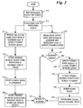
- FIG. 2 is a data flow diagram depicting steps that may be performed to provision additional services in a network environment in accordance with one embodiment of the present invention.
- the present invention will be described with respect to preferred embodiments in a specific context, namely, the provisioning of additional wavelengths in a SONET telephony network.
- the invention may also be applied, however, to other services that require the provisioning of additional hardware or software capabilities to enable the services, such as T1 lines, satellite services, application services and the like.
- reference numeral 100 designates a network diagram of a portion of a telephony network embodying features of one embodiment of the present invention. It should be noted that one of ordinary skill in the art will realize that the network diagram 100 has been simplified to better illustrate features of the present invention. Well-known elements have not been shown, but are nonetheless part of a telephony network embodying features of the present invention.
- a network embodying the present invention may include amplifiers, power supplies, maintenance systems, gateways, routers, firewalls, and the like.
- the network diagram 100 comprises line origination equipment 110 , line termination equipment 112 , a provisioning system 114 , a capacity planning system 116 , a procurement system 117 , a service provider network server 118 , a vendor network server 120 , and a vendor operations and planning system 122 .
- the line origination equipment 110 and the line termination equipment 112 are communicatively coupled via a first telecommunications network 130 .
- the first telecommunications network 130 may be, for example, a network such as the Internet, a local-area network (LAN), a wide-area network (WAN), a Public-Switched Telephone Network (PSTN), a wireless communications network, or the like, for providing communication services between the line origination equipment 110 and the line termination equipment 112 .
- the line origination equipment 110 may be located in a first city (indicated in FIG. 1 by the label “City A”), and the line termination equipment 112 may be located in a second city (indicated in FIG. 1 by the label “City B”).
- the line origination equipment 110 and the line termination equipment 112 may include a dense wave division multiplexer (DWDM), and the first telecommunications network 130 may include a series of optical amplifiers.
- DWDM dense wave division multiplexer
- the fiber optic transmission network is capable of providing communications over multiple wavelengths.
- the DWDM is generally equipped with high-capacity multiplexers/de-multiplexers.
- the provisioning system 114 is communicatively coupled to the line origination equipment 110 and the line termination equipment 112 , such that the provisioning system 114 receives status information from the line origination equipment 110 and the line termination equipment 112 .
- the status information may include, for example, the total number of wavelengths installed and the number of wavelengths in service.
- the provisioning system 114 is preferably communicatively coupled to the line termination equipment 112 via a second telecommunications network 132 separate from the first telecommunications network 130 .
- the second telecommunications network 132 may be, for example, a network such as the Internet, a LAN, WAN, PSTN, wireless communications network, or the like.
- the first telecommunications network 130 and the second telecommunications network 132 utilize the PSTN, but use different routes. In this manner, if the first telecommunications network 130 fails, then the provisioning system 114 would likely remain communicatively coupled to the line termination equipment 112 .
- provisioning system 114 is communicatively coupled to the service provider network server 118 such that the provisioning system 114 may indicate to the service provider network server 118 when new services, wavelengths, or other provisionable resources have been placed into service.
- the capacity planning system 116 and the procurement system 117 are preferably communicatively coupled to the service provider network server 118 .
- the capacity planning system 116 communicates to the service provider network server 118 information regarding the need for additional equipment to be installed in the line origination equipment 110 , the line termination equipment 112 , or elsewhere to provide for expected growth and increased capacity.
- the capacity planning system 116 utilizes growth models and predicts when additional equipment should be installed and the amount of additional equipment that should be installed.
- the procurement system 117 preferably handles the generation of invoices and purchase orders, and initiates payment for goods and services received.
- the service provider network server 118 is communicatively coupled to the vendor network server 120 via the Internet 134 .
- FIG. 1 illustrates the preferred embodiment in which the Internet 134 is utilized for communications between the service provider network server 118 and the vendor network server 120 .
- other types of communications links may be used, such as, for example, a direct link, a dial-up connection, a satellite connection, other wireless connections, or the like.
- the vendor network server 120 is communicatively coupled to the vendor operations and planning system.
- the vendor operations and planning system 122 interacts with the service provider network server 118 to generate invoices and purchase orders for equipment or services placed into service.
- the provisioning system 114 , the capacity planning system 116 , the procurement system 117 , and the service provider network server 118 are preferably communicatively coupled via an internal data network (IDN), such as a LAN, WAN, or the like, utilizing common communications protocols, such as TCP/IP.
- IDN internal data network
- each component may issue a machine-to-machine language (MML) request to establish a communications channel as is known in the art.
- MML machine-to-machine language
- HTTP hyper-text markup language
- TL1 commands are used for communications between other network elements.
- FIG. 2 is a data flow diagram depicting steps that may be performed in accordance with one embodiment of the present invention.
- FIG. 2 discusses the operation of one embodiment of the present invention in which a wavelength is placed into service.
- the process begins in step 210 , wherein a new wavelength, or other equipment or service, is placed into service.
- a new wavelength, or other equipment or service requires a craft engineer to place the wavelength into a maintenance state.
- Tests are performed on the equipment and the wavelength for a specified period of time, usually about 72 hours. Upon successful completion of the tests, the wavelength, or other equipment or service, is placed into full service in which the wavelength is allowed to be used for normal user traffic.
- step 212 after the wavelength has been placed into full service, the line origination equipment 110 and/or the line termination equipment 112 transmits a notification to the provisioning system 114 indicating that the wavelength is prepared for customer use.
- the provisioning system 114 then enables the wavelength for customer use.
- Processing then preferably proceeds along independent parallel paths, as indicated by the paths beginning with steps 214 and 224 .
- the path beginning with step 214 processes the new wavelength and initiates the process of generating an invoice and a purchase order for the new wavelength and the equipment associated to the new wavelength.
- the path beginning with step 224 determines whether additional equipment should be added to prepare for additional capacity at a later date.
- the provisioning system 114 transmits notification of the additional equipment placed into service to the service provider network server 118 .
- the service provider network server 118 transmits a notification to the vendor of the additional equipment that has been placed into service.
- the notification is transmitted to the vendor via an email message transmitted over the Internet 134 .
- the notification may be sent by facsimile, postal mail, voice mail, or the like transmitted over the PSTN, wireless communications network, LAN, WAN, direct connection, or the like.
- the vendor submits an invoice to the service provider if the additional equipment has not yet been invoiced.
- the vendor submits the invoice via the vendor operations and planning system 122 and the vendor network server 120 .
- the invoice is preferably submitted electronically, but may also be submitted by facsimile, postal mail, voice mail, or the like transmitted over the PSTN, wireless communications network, LAN, WAN, direct connection, or the like.
- step 220 the invoice is received by the procurement system 117 via the service provider network server 118 .
- the procurement system 117 processes the invoice and generates a purchase order, thereby initiating payment for the goods and/or services received.
- the purchase order is transmitted from the procurement system 117 to the vendor operations and planning system 122 via the service provider network server 118 and the vendor network server 120 .
- this step is performed automatically without human intervention. It may be desirable, however, to require approval or other human interaction on some or all transactions.
- step 222 processing returns to the beginning wherein the process is repeated for the next wavelength placed into service.
- processing begins in step 224 , wherein the line origination equipment 110 and/or the line termination equipment 112 transmits notification of the equipment or wavelength placed into service to the capacity planning system 116 .
- the capacity planning system 116 determines whether or not sufficient spare resources remain available or if additional equipment should be purchased and installed such that sufficient resources will be available to meet future demands.
- step 226 a determination is made whether or not additional equipment should be purchased and installed. If a determination is made that additional equipment should not be purchased and installed at this time, then processing proceeds to step 222 wherein processing returns to the beginning.
- processing proceeds to step 228 , wherein the capacity planning system 116 transmits a request for an invoice to the service provider network server 118 .
- the service provider network server 118 forwards the request for an invoice to the vendor network server 120 and vendor operations and planning system 122 via the Internet 134 .
- the vendor operations and planning system 122 determines the resources needed, such as equipment, personnel, and the like, and generates an invoice for the goods and services.
- the invoice is transmitted from the vendor operations and planning system 122 to the procurement system 117 .
- the procurement system responds by issuing a purchase order. Thereafter, the equipment may be installed and tested.
- embodiments of the present invention provide automatic notification of equipment and services placed into service. It should also be appreciated that such a system allows for efficient cost-sharing and risk-sharing arrangements to be implemented.
- embodiments of the present invention may be used in which the vendor installs equipment into the service providers network. As capabilities are utilized, invoices and purchase orders are automatically generated to effect payment of the services. Furthermore, by having the equipment installed previously, the additional capabilities may be brought into full service in a minimal amount of time. Thus, the service provider is able to maintain a competitive advantage and compete cost-effectively with competitors.
Abstract
Description
Claims (20)
Priority Applications (1)
| Application Number | Priority Date | Filing Date | Title |
|---|---|---|---|
| US13/162,338 US9092791B2 (en) | 2003-11-10 | 2011-06-16 | Provisioning system for network resources |
Applications Claiming Priority (2)
| Application Number | Priority Date | Filing Date | Title |
|---|---|---|---|
| US10/705,000 US7978840B2 (en) | 2003-11-10 | 2003-11-10 | Provisioning system for network resources |
| US13/162,338 US9092791B2 (en) | 2003-11-10 | 2011-06-16 | Provisioning system for network resources |
Related Parent Applications (1)
| Application Number | Title | Priority Date | Filing Date |
|---|---|---|---|
| US10/705,000 Division US7978840B2 (en) | 2003-11-10 | 2003-11-10 | Provisioning system for network resources |
Publications (2)
| Publication Number | Publication Date |
|---|---|
| US20110251939A1 US20110251939A1 (en) | 2011-10-13 |
| US9092791B2 true US9092791B2 (en) | 2015-07-28 |
Family
ID=34552252
Family Applications (2)
| Application Number | Title | Priority Date | Filing Date |
|---|---|---|---|
| US10/705,000 Expired - Fee Related US7978840B2 (en) | 2003-11-10 | 2003-11-10 | Provisioning system for network resources |
| US13/162,338 Expired - Fee Related US9092791B2 (en) | 2003-11-10 | 2011-06-16 | Provisioning system for network resources |
Family Applications Before (1)
| Application Number | Title | Priority Date | Filing Date |
|---|---|---|---|
| US10/705,000 Expired - Fee Related US7978840B2 (en) | 2003-11-10 | 2003-11-10 | Provisioning system for network resources |
Country Status (1)
| Country | Link |
|---|---|
| US (2) | US7978840B2 (en) |
Families Citing this family (5)
| Publication number | Priority date | Publication date | Assignee | Title |
|---|---|---|---|---|
| US7493418B2 (en) * | 2003-12-18 | 2009-02-17 | International Business Machines Corporation | Generic method for resource monitoring configuration in provisioning systems |
| US20090248722A1 (en) * | 2008-03-27 | 2009-10-01 | International Business Machines Corporation | Clustering analytic functions |
| US9363143B2 (en) | 2008-03-27 | 2016-06-07 | International Business Machines Corporation | Selective computation using analytic functions |
| US7882219B2 (en) * | 2008-03-27 | 2011-02-01 | International Business Machines Corporation | Deploying analytic functions |
| US8560544B2 (en) | 2010-09-15 | 2013-10-15 | International Business Machines Corporation | Clustering of analytic functions |
Citations (7)
| Publication number | Priority date | Publication date | Assignee | Title |
|---|---|---|---|---|
| US5511113A (en) * | 1993-06-18 | 1996-04-23 | Fujitsu Limited | Service switching point and system for creating detailed charging information |
| US20040158507A1 (en) | 2002-12-06 | 2004-08-12 | Meek Robert B. | Inventory management and replenishment system |
| US20050060388A1 (en) | 2002-08-26 | 2005-03-17 | Hitachi, Ltd. | Method for modifying computer configuration and configuration of program which operates on computer, and computing device and system for implementing the method |
| US7080035B1 (en) | 2000-03-20 | 2006-07-18 | Bellsouth Intellectual Property Corp. | System and method for notifying an electronic billing vendor of a customer status change |
| US7116682B1 (en) * | 2001-03-19 | 2006-10-03 | Cisco Technology, Inc. | Methods and apparatus for dynamic bandwidth adjustment |
| US7302405B2 (en) | 2003-02-19 | 2007-11-27 | Accenture Global Services Gmbh | Methods for managing and developing sourcing and procurement operations |
| US7334225B2 (en) * | 2003-04-28 | 2008-02-19 | International Business Machines Corporation | Method, system, and computer program product for on demand enablement of dormant computing resources |
-
2003
- 2003-11-10 US US10/705,000 patent/US7978840B2/en not_active Expired - Fee Related
-
2011
- 2011-06-16 US US13/162,338 patent/US9092791B2/en not_active Expired - Fee Related
Patent Citations (7)
| Publication number | Priority date | Publication date | Assignee | Title |
|---|---|---|---|---|
| US5511113A (en) * | 1993-06-18 | 1996-04-23 | Fujitsu Limited | Service switching point and system for creating detailed charging information |
| US7080035B1 (en) | 2000-03-20 | 2006-07-18 | Bellsouth Intellectual Property Corp. | System and method for notifying an electronic billing vendor of a customer status change |
| US7116682B1 (en) * | 2001-03-19 | 2006-10-03 | Cisco Technology, Inc. | Methods and apparatus for dynamic bandwidth adjustment |
| US20050060388A1 (en) | 2002-08-26 | 2005-03-17 | Hitachi, Ltd. | Method for modifying computer configuration and configuration of program which operates on computer, and computing device and system for implementing the method |
| US20040158507A1 (en) | 2002-12-06 | 2004-08-12 | Meek Robert B. | Inventory management and replenishment system |
| US7302405B2 (en) | 2003-02-19 | 2007-11-27 | Accenture Global Services Gmbh | Methods for managing and developing sourcing and procurement operations |
| US7334225B2 (en) * | 2003-04-28 | 2008-02-19 | International Business Machines Corporation | Method, system, and computer program product for on demand enablement of dormant computing resources |
Also Published As
| Publication number | Publication date |
|---|---|
| US7978840B2 (en) | 2011-07-12 |
| US20110251939A1 (en) | 2011-10-13 |
| US20050102193A1 (en) | 2005-05-12 |
Similar Documents
| Publication | Publication Date | Title |
|---|---|---|
| US9092791B2 (en) | Provisioning system for network resources | |
| US20020004390A1 (en) | Method and system for managing telecommunications services and network interconnections | |
| US7677447B2 (en) | Method and system for automated teller machine remote diagnostics and configuration | |
| US20120209762A1 (en) | Transaction processing system and method | |
| EP1387552B1 (en) | Order entry system for telecommunications network service | |
| CN1885780B (en) | Centralized off-line charge and on-line charge method and system | |
| US6542593B1 (en) | Rules database server in a hybrid communication system architecture | |
| CA2475103A1 (en) | Method and apparatus for integrated network planning and business modeling | |
| US6535727B1 (en) | Method and apparatus for providing pre-pay and post-pay communication services using the same integrated | |
| WO2002065360A2 (en) | Method and apparatus providing convergent solution to end-to-end, adaptive business application management | |
| US20050281199A1 (en) | Method and system for communications routing | |
| Andromeda et al. | Techno-economic analysis from implementing sd-wan with 4g/lte, a case study in xyz company | |
| EP1122970A2 (en) | Digital content downloading system using networks | |
| AU2007200792A1 (en) | Network layer integration for supporting voice over internet protocol and internet protocol television services | |
| US20150148003A1 (en) | Adaptive Request Processing Service For Charging Requests | |
| US8224338B2 (en) | Method and apparatus for joint optimization of dedicated and radio access networks | |
| US6760418B1 (en) | Method and apparatus for providing pre-pay and post-pay communication services using a switching system to monitor call duration | |
| US20060088050A1 (en) | System for a next generation wireless intelligent services engine (WISENG) | |
| US20020136375A1 (en) | System and method for utilization of call processing platform for ecommerce transactions | |
| Misra | OSS for Telecom Networks: An Introduction to Networks Management | |
| US20010010047A1 (en) | Process, internet access device, exchange and charging device for charging for internet services | |
| US7779098B1 (en) | Methods for identifying and recovering stranded and access-no-revenue network circuits | |
| US20050036598A1 (en) | System and method for reconciling billing mismatch | |
| US20070275699A1 (en) | Methods, computer networks, and computer program products that facilitate providing broadband services wirelessly to third party users via a mesh network of customer premise equipment | |
| EP1172987A3 (en) | System for the transmission of data |
Legal Events
| Date | Code | Title | Description |
|---|---|---|---|
| AS | Assignment |
Owner name: VERIZON BUSINESS GLOBAL LLC, VIRGINIA Free format text: CHANGE OF NAME;ASSIGNOR:MCI LLC;REEL/FRAME:032633/0983 Effective date: 20061120 Owner name: MCI, INC., VIRGINIA Free format text: MERGER;ASSIGNOR:WORLDCOM, INC.;REEL/FRAME:032632/0913 Effective date: 20040420 Owner name: MCI LLC, VIRGINIA Free format text: MERGER;ASSIGNOR:MCI INC.;REEL/FRAME:032633/0085 Effective date: 20060106 |
|
| AS | Assignment |
Owner name: VERIZON PATENT AND LICENSING INC., NEW JERSEY Free format text: ASSIGNMENT OF ASSIGNORS INTEREST;ASSIGNOR:VERIZON BUSINESS GLOBAL LLC;REEL/FRAME:032734/0502 Effective date: 20140409 |
|
| AS | Assignment |
Owner name: WORLDCOM, INC., VIRGINIA Free format text: ASSIGNMENT OF ASSIGNORS INTEREST;ASSIGNORS:DAY, RONALD D.;PITCHFORTH, DONALD;REEL/FRAME:035867/0893 Effective date: 20031107 |
|
| STCF | Information on status: patent grant |
Free format text: PATENTED CASE |
|
| AS | Assignment |
Owner name: VERIZON PATENT AND LICENSING INC., NEW JERSEY Free format text: CORRECTIVE ASSIGNMENT TO CORRECT THE ASSIGNEE PREVIOUSLY RECORDED AT REEL: 032734 FRAME: 0502. ASSIGNOR(S) HEREBY CONFIRMS THE ASSIGNMENT;ASSIGNOR:VERIZON BUSINESS GLOBAL LLC;REEL/FRAME:044626/0088 Effective date: 20140409 |
|
| FEPP | Fee payment procedure |
Free format text: MAINTENANCE FEE REMINDER MAILED (ORIGINAL EVENT CODE: REM.); ENTITY STATUS OF PATENT OWNER: LARGE ENTITY |
|
| LAPS | Lapse for failure to pay maintenance fees |
Free format text: PATENT EXPIRED FOR FAILURE TO PAY MAINTENANCE FEES (ORIGINAL EVENT CODE: EXP.); ENTITY STATUS OF PATENT OWNER: LARGE ENTITY |
|
| STCH | Information on status: patent discontinuation |
Free format text: PATENT EXPIRED DUE TO NONPAYMENT OF MAINTENANCE FEES UNDER 37 CFR 1.362 |
|
| FP | Lapsed due to failure to pay maintenance fee |
Effective date: 20190728 |