US9090046B2 - Ceramic coated article and process for applying ceramic coating - Google Patents
Ceramic coated article and process for applying ceramic coating Download PDFInfo
- Publication number
- US9090046B2 US9090046B2 US13/747,292 US201313747292A US9090046B2 US 9090046 B2 US9090046 B2 US 9090046B2 US 201313747292 A US201313747292 A US 201313747292A US 9090046 B2 US9090046 B2 US 9090046B2
- Authority
- US
- United States
- Prior art keywords
- ceramic
- coating
- ceramic body
- region
- approximately
- Prior art date
- Legal status (The legal status is an assumption and is not a legal conclusion. Google has not performed a legal analysis and makes no representation as to the accuracy of the status listed.)
- Active
Links
Images


Classifications
-
- B—PERFORMING OPERATIONS; TRANSPORTING
- B32—LAYERED PRODUCTS
- B32B—LAYERED PRODUCTS, i.e. PRODUCTS BUILT-UP OF STRATA OF FLAT OR NON-FLAT, e.g. CELLULAR OR HONEYCOMB, FORM
- B32B18/00—Layered products essentially comprising ceramics, e.g. refractory products
-
- C—CHEMISTRY; METALLURGY
- C04—CEMENTS; CONCRETE; ARTIFICIAL STONE; CERAMICS; REFRACTORIES
- C04B—LIME, MAGNESIA; SLAG; CEMENTS; COMPOSITIONS THEREOF, e.g. MORTARS, CONCRETE OR LIKE BUILDING MATERIALS; ARTIFICIAL STONE; CERAMICS; REFRACTORIES; TREATMENT OF NATURAL STONE
- C04B35/00—Shaped ceramic products characterised by their composition; Ceramics compositions; Processing powders of inorganic compounds preparatory to the manufacturing of ceramic products
- C04B35/50—Shaped ceramic products characterised by their composition; Ceramics compositions; Processing powders of inorganic compounds preparatory to the manufacturing of ceramic products based on rare-earth compounds
- C04B35/505—Shaped ceramic products characterised by their composition; Ceramics compositions; Processing powders of inorganic compounds preparatory to the manufacturing of ceramic products based on rare-earth compounds based on yttrium oxide
-
- C—CHEMISTRY; METALLURGY
- C04—CEMENTS; CONCRETE; ARTIFICIAL STONE; CERAMICS; REFRACTORIES
- C04B—LIME, MAGNESIA; SLAG; CEMENTS; COMPOSITIONS THEREOF, e.g. MORTARS, CONCRETE OR LIKE BUILDING MATERIALS; ARTIFICIAL STONE; CERAMICS; REFRACTORIES; TREATMENT OF NATURAL STONE
- C04B35/00—Shaped ceramic products characterised by their composition; Ceramics compositions; Processing powders of inorganic compounds preparatory to the manufacturing of ceramic products
- C04B35/01—Shaped ceramic products characterised by their composition; Ceramics compositions; Processing powders of inorganic compounds preparatory to the manufacturing of ceramic products based on oxide ceramics
- C04B35/10—Shaped ceramic products characterised by their composition; Ceramics compositions; Processing powders of inorganic compounds preparatory to the manufacturing of ceramic products based on oxide ceramics based on aluminium oxide
-
- C—CHEMISTRY; METALLURGY
- C04—CEMENTS; CONCRETE; ARTIFICIAL STONE; CERAMICS; REFRACTORIES
- C04B—LIME, MAGNESIA; SLAG; CEMENTS; COMPOSITIONS THEREOF, e.g. MORTARS, CONCRETE OR LIKE BUILDING MATERIALS; ARTIFICIAL STONE; CERAMICS; REFRACTORIES; TREATMENT OF NATURAL STONE
- C04B35/00—Shaped ceramic products characterised by their composition; Ceramics compositions; Processing powders of inorganic compounds preparatory to the manufacturing of ceramic products
- C04B35/622—Forming processes; Processing powders of inorganic compounds preparatory to the manufacturing of ceramic products
- C04B35/62222—Forming processes; Processing powders of inorganic compounds preparatory to the manufacturing of ceramic products obtaining ceramic coatings
-
- C—CHEMISTRY; METALLURGY
- C04—CEMENTS; CONCRETE; ARTIFICIAL STONE; CERAMICS; REFRACTORIES
- C04B—LIME, MAGNESIA; SLAG; CEMENTS; COMPOSITIONS THEREOF, e.g. MORTARS, CONCRETE OR LIKE BUILDING MATERIALS; ARTIFICIAL STONE; CERAMICS; REFRACTORIES; TREATMENT OF NATURAL STONE
- C04B35/00—Shaped ceramic products characterised by their composition; Ceramics compositions; Processing powders of inorganic compounds preparatory to the manufacturing of ceramic products
- C04B35/622—Forming processes; Processing powders of inorganic compounds preparatory to the manufacturing of ceramic products
- C04B35/626—Preparing or treating the powders individually or as batches ; preparing or treating macroscopic reinforcing agents for ceramic products, e.g. fibres; mechanical aspects section B
- C04B35/62605—Treating the starting powders individually or as mixtures
- C04B35/62645—Thermal treatment of powders or mixtures thereof other than sintering
- C04B35/62665—Flame, plasma or melting treatment
-
- C—CHEMISTRY; METALLURGY
- C04—CEMENTS; CONCRETE; ARTIFICIAL STONE; CERAMICS; REFRACTORIES
- C04B—LIME, MAGNESIA; SLAG; CEMENTS; COMPOSITIONS THEREOF, e.g. MORTARS, CONCRETE OR LIKE BUILDING MATERIALS; ARTIFICIAL STONE; CERAMICS; REFRACTORIES; TREATMENT OF NATURAL STONE
- C04B35/00—Shaped ceramic products characterised by their composition; Ceramics compositions; Processing powders of inorganic compounds preparatory to the manufacturing of ceramic products
- C04B35/622—Forming processes; Processing powders of inorganic compounds preparatory to the manufacturing of ceramic products
- C04B35/626—Preparing or treating the powders individually or as batches ; preparing or treating macroscopic reinforcing agents for ceramic products, e.g. fibres; mechanical aspects section B
- C04B35/62605—Treating the starting powders individually or as mixtures
- C04B35/62645—Thermal treatment of powders or mixtures thereof other than sintering
- C04B35/62675—Thermal treatment of powders or mixtures thereof other than sintering characterised by the treatment temperature
-
- C—CHEMISTRY; METALLURGY
- C04—CEMENTS; CONCRETE; ARTIFICIAL STONE; CERAMICS; REFRACTORIES
- C04B—LIME, MAGNESIA; SLAG; CEMENTS; COMPOSITIONS THEREOF, e.g. MORTARS, CONCRETE OR LIKE BUILDING MATERIALS; ARTIFICIAL STONE; CERAMICS; REFRACTORIES; TREATMENT OF NATURAL STONE
- C04B41/00—After-treatment of mortars, concrete, artificial stone or ceramics; Treatment of natural stone
- C04B41/009—After-treatment of mortars, concrete, artificial stone or ceramics; Treatment of natural stone characterised by the material treated
-
- C—CHEMISTRY; METALLURGY
- C04—CEMENTS; CONCRETE; ARTIFICIAL STONE; CERAMICS; REFRACTORIES
- C04B—LIME, MAGNESIA; SLAG; CEMENTS; COMPOSITIONS THEREOF, e.g. MORTARS, CONCRETE OR LIKE BUILDING MATERIALS; ARTIFICIAL STONE; CERAMICS; REFRACTORIES; TREATMENT OF NATURAL STONE
- C04B41/00—After-treatment of mortars, concrete, artificial stone or ceramics; Treatment of natural stone
- C04B41/45—Coating or impregnating, e.g. injection in masonry, partial coating of green or fired ceramics, organic coating compositions for adhering together two concrete elements
- C04B41/4505—Coating or impregnating, e.g. injection in masonry, partial coating of green or fired ceramics, organic coating compositions for adhering together two concrete elements characterised by the method of application
- C04B41/4523—Coating or impregnating, e.g. injection in masonry, partial coating of green or fired ceramics, organic coating compositions for adhering together two concrete elements characterised by the method of application applied from the molten state ; Thermal spraying, e.g. plasma spraying
- C04B41/4527—Plasma spraying
-
- C—CHEMISTRY; METALLURGY
- C04—CEMENTS; CONCRETE; ARTIFICIAL STONE; CERAMICS; REFRACTORIES
- C04B—LIME, MAGNESIA; SLAG; CEMENTS; COMPOSITIONS THEREOF, e.g. MORTARS, CONCRETE OR LIKE BUILDING MATERIALS; ARTIFICIAL STONE; CERAMICS; REFRACTORIES; TREATMENT OF NATURAL STONE
- C04B41/00—After-treatment of mortars, concrete, artificial stone or ceramics; Treatment of natural stone
- C04B41/45—Coating or impregnating, e.g. injection in masonry, partial coating of green or fired ceramics, organic coating compositions for adhering together two concrete elements
- C04B41/50—Coating or impregnating, e.g. injection in masonry, partial coating of green or fired ceramics, organic coating compositions for adhering together two concrete elements with inorganic materials
- C04B41/5025—Coating or impregnating, e.g. injection in masonry, partial coating of green or fired ceramics, organic coating compositions for adhering together two concrete elements with inorganic materials with ceramic materials
- C04B41/5031—Alumina
- C04B41/5032—Aluminates
-
- C—CHEMISTRY; METALLURGY
- C04—CEMENTS; CONCRETE; ARTIFICIAL STONE; CERAMICS; REFRACTORIES
- C04B—LIME, MAGNESIA; SLAG; CEMENTS; COMPOSITIONS THEREOF, e.g. MORTARS, CONCRETE OR LIKE BUILDING MATERIALS; ARTIFICIAL STONE; CERAMICS; REFRACTORIES; TREATMENT OF NATURAL STONE
- C04B41/00—After-treatment of mortars, concrete, artificial stone or ceramics; Treatment of natural stone
- C04B41/45—Coating or impregnating, e.g. injection in masonry, partial coating of green or fired ceramics, organic coating compositions for adhering together two concrete elements
- C04B41/50—Coating or impregnating, e.g. injection in masonry, partial coating of green or fired ceramics, organic coating compositions for adhering together two concrete elements with inorganic materials
- C04B41/5025—Coating or impregnating, e.g. injection in masonry, partial coating of green or fired ceramics, organic coating compositions for adhering together two concrete elements with inorganic materials with ceramic materials
- C04B41/5042—Zirconium oxides or zirconates; Hafnium oxides or hafnates
-
- C—CHEMISTRY; METALLURGY
- C04—CEMENTS; CONCRETE; ARTIFICIAL STONE; CERAMICS; REFRACTORIES
- C04B—LIME, MAGNESIA; SLAG; CEMENTS; COMPOSITIONS THEREOF, e.g. MORTARS, CONCRETE OR LIKE BUILDING MATERIALS; ARTIFICIAL STONE; CERAMICS; REFRACTORIES; TREATMENT OF NATURAL STONE
- C04B41/00—After-treatment of mortars, concrete, artificial stone or ceramics; Treatment of natural stone
- C04B41/45—Coating or impregnating, e.g. injection in masonry, partial coating of green or fired ceramics, organic coating compositions for adhering together two concrete elements
- C04B41/50—Coating or impregnating, e.g. injection in masonry, partial coating of green or fired ceramics, organic coating compositions for adhering together two concrete elements with inorganic materials
- C04B41/5025—Coating or impregnating, e.g. injection in masonry, partial coating of green or fired ceramics, organic coating compositions for adhering together two concrete elements with inorganic materials with ceramic materials
- C04B41/5045—Rare-earth oxides
-
- C—CHEMISTRY; METALLURGY
- C04—CEMENTS; CONCRETE; ARTIFICIAL STONE; CERAMICS; REFRACTORIES
- C04B—LIME, MAGNESIA; SLAG; CEMENTS; COMPOSITIONS THEREOF, e.g. MORTARS, CONCRETE OR LIKE BUILDING MATERIALS; ARTIFICIAL STONE; CERAMICS; REFRACTORIES; TREATMENT OF NATURAL STONE
- C04B41/00—After-treatment of mortars, concrete, artificial stone or ceramics; Treatment of natural stone
- C04B41/53—After-treatment of mortars, concrete, artificial stone or ceramics; Treatment of natural stone involving the removal of at least part of the materials of the treated article, e.g. etching, drying of hardened concrete
-
- C—CHEMISTRY; METALLURGY
- C04—CEMENTS; CONCRETE; ARTIFICIAL STONE; CERAMICS; REFRACTORIES
- C04B—LIME, MAGNESIA; SLAG; CEMENTS; COMPOSITIONS THEREOF, e.g. MORTARS, CONCRETE OR LIKE BUILDING MATERIALS; ARTIFICIAL STONE; CERAMICS; REFRACTORIES; TREATMENT OF NATURAL STONE
- C04B41/00—After-treatment of mortars, concrete, artificial stone or ceramics; Treatment of natural stone
- C04B41/80—After-treatment of mortars, concrete, artificial stone or ceramics; Treatment of natural stone of only ceramics
- C04B41/81—Coating or impregnation
- C04B41/85—Coating or impregnation with inorganic materials
- C04B41/87—Ceramics
-
- C—CHEMISTRY; METALLURGY
- C23—COATING METALLIC MATERIAL; COATING MATERIAL WITH METALLIC MATERIAL; CHEMICAL SURFACE TREATMENT; DIFFUSION TREATMENT OF METALLIC MATERIAL; COATING BY VACUUM EVAPORATION, BY SPUTTERING, BY ION IMPLANTATION OR BY CHEMICAL VAPOUR DEPOSITION, IN GENERAL; INHIBITING CORROSION OF METALLIC MATERIAL OR INCRUSTATION IN GENERAL
- C23C—COATING METALLIC MATERIAL; COATING MATERIAL WITH METALLIC MATERIAL; SURFACE TREATMENT OF METALLIC MATERIAL BY DIFFUSION INTO THE SURFACE, BY CHEMICAL CONVERSION OR SUBSTITUTION; COATING BY VACUUM EVAPORATION, BY SPUTTERING, BY ION IMPLANTATION OR BY CHEMICAL VAPOUR DEPOSITION, IN GENERAL
- C23C4/00—Coating by spraying the coating material in the molten state, e.g. by flame, plasma or electric discharge
- C23C4/12—Coating by spraying the coating material in the molten state, e.g. by flame, plasma or electric discharge characterised by the method of spraying
- C23C4/134—Plasma spraying
-
- C—CHEMISTRY; METALLURGY
- C04—CEMENTS; CONCRETE; ARTIFICIAL STONE; CERAMICS; REFRACTORIES
- C04B—LIME, MAGNESIA; SLAG; CEMENTS; COMPOSITIONS THEREOF, e.g. MORTARS, CONCRETE OR LIKE BUILDING MATERIALS; ARTIFICIAL STONE; CERAMICS; REFRACTORIES; TREATMENT OF NATURAL STONE
- C04B41/00—After-treatment of mortars, concrete, artificial stone or ceramics; Treatment of natural stone
- C04B41/45—Coating or impregnating, e.g. injection in masonry, partial coating of green or fired ceramics, organic coating compositions for adhering together two concrete elements
- C04B41/4505—Coating or impregnating, e.g. injection in masonry, partial coating of green or fired ceramics, organic coating compositions for adhering together two concrete elements characterised by the method of application
- C04B41/4545—Coating or impregnating, e.g. injection in masonry, partial coating of green or fired ceramics, organic coating compositions for adhering together two concrete elements characterised by the method of application applied as a powdery material
-
- Y—GENERAL TAGGING OF NEW TECHNOLOGICAL DEVELOPMENTS; GENERAL TAGGING OF CROSS-SECTIONAL TECHNOLOGIES SPANNING OVER SEVERAL SECTIONS OF THE IPC; TECHNICAL SUBJECTS COVERED BY FORMER USPC CROSS-REFERENCE ART COLLECTIONS [XRACs] AND DIGESTS
- Y10—TECHNICAL SUBJECTS COVERED BY FORMER USPC
- Y10T—TECHNICAL SUBJECTS COVERED BY FORMER US CLASSIFICATION
- Y10T428/00—Stock material or miscellaneous articles
- Y10T428/24—Structurally defined web or sheet [e.g., overall dimension, etc.]
- Y10T428/24479—Structurally defined web or sheet [e.g., overall dimension, etc.] including variation in thickness
- Y10T428/24562—Interlaminar spaces
Definitions
- Embodiments of the present invention relate, in general, to ceramic coated articles and to a process for applying a ceramic coating to a ceramic body.
- devices are fabricated by a number of manufacturing processes producing structures of an ever-decreasing size.
- Some manufacturing processes such as plasma etch and plasma clean processes expose a substrate to a high-speed stream of plasma to etch or clean the substrate.
- the plasma may be highly corrosive, and may corrode processing chambers and other surfaces that are exposed to the plasma. This corrosion may generate particles, which frequently contaminate the substrate that is being processed, contributing to device defects.
- chamber materials have been developed that are resistant to plasmas.
- plasma resistant materials include ceramics composed of Al 2 O 3 , AlN, SiC, Y 2 O 3 , quartz, and ZrO2.
- Different ceramics provide different material properties, such as plasma resistance, rigidity, flexural strength, thermal shock resistance, and so on.
- difference ceramics have different material costs. Accordingly, some ceramics have superior plasma resistance, other ceramics have lower costs, and still other ceramics have superior flexural strength and/or thermal shock resistance.
- a ceramic article in one embodiment, includes a ceramic body and a ceramic coating on the ceramic body.
- a ceramic body comprising Al 2 O 3 is roughened to a roughness of approximately 140 micro-inches ( ⁇ in) to 240 ⁇ in.
- the ceramic body is subsequently cleaned and then coated with a ceramic coating.
- the ceramic coating includes a compound of Y 4 Al 2 O 9 (YAM) and a solid solution of Y 2 -xZr x O 3 . The ceramic coating is then polished.
- FIG. 1 illustrates an exemplary architecture of a manufacturing system, in accordance with one embodiment of the present invention
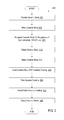
- FIG. 2 is a flow chart showing a process for manufacturing a coated ceramic article, in accordance with embodiments of the present invention
- FIG. 3 shows cross sectional side views of a ceramic article during different stages of a manufacturing process, in accordance with embodiments of the present invention
- FIG. 4A illustrates a bottom view of a ceramic lid for an etcher, in accordance with one embodiment of the present invention.
- FIG. 4B illustrates a side view of a ceramic lid for an etcher, in accordance with one embodiment of the present invention.
- FIG. 5 shows various micrographs of a sample of a ceramic article, in accordance with embodiments of the present invention.
- FIG. 6 shows additional micrographs of a ceramic coating's surface at various magnification levels before the ceramic coating is polished, and after the ceramic coating has been polished, in accordance with embodiments of the present invention.
- Embodiments of the invention are directed to a process for coating a ceramic body with a ceramic coating, and to a ceramic article (e.g., a lid for a plasma etch reactor) created using such a coating process.
- a ceramic body is roughened, cleaned and coated with a ceramic coating. Parameters for the roughening, the cleaning and the coating may be optimized to maximize an adhesion strength of the ceramic coating to the ceramic body, and thus to reduce future delamination of the ceramic coating from the ceramic body.
- the ceramic coating may then be machined to remove jagged edges and/or to reduce a surface roughness. The machining may further reduce delamination of the ceramic coating from the ceramic body.
- the ceramic coating of the ceramic article may be highly resistant to plasma etching, and the ceramic body may have superior mechanical properties such as a high flexural strength and a high thermal shock resistance.
- Al 2 O 3 has a high thermo-mechanical strength, but also has relatively high aluminum contamination levels and a low plasma resistance.
- Y 2 O 3 containing ceramics have enhanced plasma resistance and a low on-wafer level aluminum contamination, but have a relatively low thermo-mechanical strength.
- the ceramic article may have the advantageous properties of a first ceramic substance (e.g., Al 2 O 3 ) and the advantageous properties of a second ceramic substance (e.g., a Y 2 O 3 containing ceramic), without the weaknesses of either ceramic substance.
- Performance properties of the coated ceramic article may include a relatively high thermal capability (e.g., ability to withstand operating temperatures of up to approximately 120° C.), a relatively long lifespan (e.g., over approximately 2 years when used in a plasma environment), low on-wafer particle and metal contamination, and a stable electrostatic chuck (ESC) leakage current performance (e.g., by blocking the formation of AlF at the ceramic article).
- a relatively high thermal capability e.g., ability to withstand operating temperatures of up to approximately 120° C.
- a relatively long lifespan e.g., over approximately 2 years when used in a plasma environment
- low on-wafer particle and metal contamination e.g., low on-wafer particle and metal contamination
- ESC stable electrostatic chuck
- the terms “about” and “approximately” are intended to mean that the nominal value presented is precise within ⁇ 10%.
- some embodiments are described herein with reference to ceramic lids and ceramic nozzles used in plasma etchers for semiconductor manufacturing. However, it should be understood that such plasma etchers may also be used to manufacture micro-electro-mechanical systems (MEMS)) devices.
- MEMS micro-electro-mechanical systems
- the ceramic articles described herein may be other structures that are exposed to plasma.
- the ceramic articles may be ceramic rings, walls, bases, gas distribution plates, shower heads, substrate holding frames, etc. of a plasma etcher, a plasma cleaner, a plasma propulsion system, and so forth.
- embodiments are described herein with reference to ceramic articles that cause reduced particle contamination when used in a process chamber for plasma rich processes.
- the ceramic articles discussed herein may also provide reduced particle contamination when used in process chambers for other processes such as plasma enhanced chemical vapor deposition (PECVD) chambers, plasma enhanced physical vapor deposition (PEPVD) chambers and plasma enhanced atomic layer deposition (PEALD) chambers, as well as non-plasma etchers, non-plasma cleaners, chemical vapor deposition (CVD) furnaces, physical vapor deposition (PVD) furnaces, and so forth.
- PECVD plasma enhanced chemical vapor deposition
- PVD plasma enhanced physical vapor deposition
- PVD plasma enhanced atomic layer deposition
- FIG. 1 illustrates an exemplary architecture of a manufacturing system 100 , in accordance with embodiments of the present invention.
- the manufacturing system 100 may be a ceramics manufacturing system.
- the manufacturing system 100 includes processing equipment 101 connected to an equipment automation layer 115 .
- the processing equipment 101 may include a bead blaster 102 , one or more wet cleaners 103 , a ceramic coater 104 and/or one or more grinders 105 .
- the manufacturing system 100 may further include one or more computing device 120 connected to the equipment automation layer 115 .
- the manufacturing system 100 may include more or fewer components.
- the manufacturing system 100 may include manually operated (e.g., off-line) processing equipment 101 without the equipment automation layer 115 or the computing device 120 .
- Bead blaster 102 is a machine configured to roughen the surface of articles such as ceramic bodies.
- Bead blaster 102 may be a bead blasting cabinet, a hand held bead blaster, or other type of bead blaster.
- Bead blaster 102 may roughen a ceramic body by bombarding the ceramic body with beads or particles.
- bead blaster 102 fires ceramic beads or particles at the ceramic body.
- the roughness achieved by the bead blaster 102 may be based on a force used to fire the beads, bead materials, bead sizes and/or processing duration.
- the bead blaster uses a range of bead sizes to roughen the ceramic article.
- a motorized abrasive pad may be used to roughen the surface of ceramic bodies.
- a sander may rotate or vibrate the abrasive pad while the abrasive pad is pressed against a surface of the ceramic article.
- a roughness achieved by the abrasive pad may depend on an applied pressure, on a vibration or rotation rate and/or on a roughness of the abrasive pad.
- Wet cleaners 103 are cleaning apparatuses that clean articles (e.g., ceramic articles) using a wet clean process.
- Wet cleaners 103 include wet baths filled with liquids, in which the ceramic body is immersed to clean the ceramic body.
- Wet cleaners 103 may agitate the wet bath using ultrasonic waves during cleaning to improve a cleaning efficacy. This is referred to herein as sonicating the wet bath.
- wet cleaners 103 include a first wet cleaner that cleans the ceramic articles using a bath of de-ionized (DI) water and a second wet cleaner that cleans the ceramic articles using a bath of acetone. Both wet cleaners 103 may sonicate the baths during cleaning processes. The wet cleaners 103 may clean the ceramic body at multiple stages during processing. For example, wet cleaners 103 may clean a ceramic article after a ceramic body has been roughened, after a ceramic coating has been applied to the ceramic body, after the ceramic article has been used in processing, and so forth.
- DI de-ionized
- dry cleaners may be used to clean the ceramic articles.
- Dry cleaners may clean ceramic articles by applying heat, by applying gas, by applying plasma, and so forth.
- Ceramic coater 104 is a machine configured to apply a ceramic coating to the surface of a body (e.g. a substrate).
- ceramic coater 104 is a plasma sprayer that plasma sprays a ceramic coating onto the ceramic body.
- the ceramic coater 104 may apply other thermal spraying techniques such as detonation spraying, wire arc spraying, high velocity oxygen fuel (HVOF) spraying, flame spraying, warm spraying and cold spraying may be used. Additionally, ceramic coater 104 may perform other coating processes such as aerosol deposition, electroplating, physical vapor deposition (PVD), ion assisted deposition (IAD) and chemical vapor deposition (CVD) may be used to form the ceramic coating.
- PVD physical vapor deposition
- IAD ion assisted deposition
- CVD chemical vapor deposition
- Grinders 105 are machines having an abrasive disk that grinds and/or polishes a surface of the ceramic article.
- the grinders 105 may include a polishing/grinding system such as a rough lapping station, a chemical mechanical planarization (CMP) device, and so forth.
- the grinders 105 may include a platen that holds a ceramic body and an abrasive disk or polishing pad that is pressed against the ceramic body while being rotated. These grinders 105 grind a surface of the ceramic coating to decrease a roughness of the ceramic coating and/or to reduce a thickness of the ceramic coating.
- the grinders 105 may grind/polish the ceramic coating in multiple steps, where each step uses an abrasive pad with a slightly different roughness and/or a different slurry (e.g., if CMP is used). For example, a first abrasive pad with a high roughness may be used to quickly grind down the ceramic coating to a desired thickness, and a second abrasive pad with a low roughness may be used to polish the ceramic coating to a desired roughness.
- the ceramic coating has a post-polished thickness of 8-10 mil (thousandth of an inch) and a post polished roughness of 6-12 ⁇ in.
- the grinders 105 may additionally include an angle grinder that grinds the ceramic coating at an angle.
- the angle grinder has an abrasive disk or pad that is held at an angle to the ceramic body.
- the angle grinder can trim the ceramic coating, and generate chamfers, rounded edges or other sloped transitions between a ceramic coating and a ceramic body.
- the equipment automation layer 115 may interconnect some or all of the manufacturing machines 101 with computing devices 120 , with other manufacturing machines, with metrology tools and/or other devices.
- the equipment automation layer 115 may include a network (e.g., a location area network (LAN)), routers, gateways, servers, data stores, and so on.
- Manufacturing machines 101 may connect to the equipment automation layer 115 via a SEMI Equipment Communications Standard/Generic Equipment Model (SECS/GEM) interface, via an Ethernet interface, and/or via other interfaces.
- SECS/GEM SEMI Equipment Communications Standard/Generic Equipment Model
- the equipment automation layer 115 enables process data (e.g., data collected by manufacturing machines 101 during a process run) to be stored in a data store (not shown).
- the computing device 120 connects directly to one or more of the manufacturing machines 101 .
- some or all manufacturing machines 101 include a programmable controller that can load, store and execute process recipes.
- the programmable controller may control temperature settings, gas and/or vacuum settings, time settings, etc. of manufacturing machines 101 .
- the programmable controller may include a main memory (e.g., read-only memory (ROM), flash memory, dynamic random access memory (DRAM), static random access memory (SRAM), etc.), and/or a secondary memory (e.g., a data storage device such as a disk drive).
- the main memory and/or secondary memory may store instructions for performing heat treatment processes described herein.
- the programmable controller may also include a processing device coupled to the main memory and/or secondary memory (e.g., via a bus) to execute the instructions.
- the processing device may be a general-purpose processing device such as a microprocessor, central processing unit, or the like.
- the processing device may also be a special-purpose processing device such as an application specific integrated circuit (ASIC), a field programmable gate array (FPGA), a digital signal processor (DSP), network processor, or the like.
- programmable controller is a programmable logic controller (PLC).
- the manufacturing machines 101 are programmed to execute recipes that will cause the manufacturing machines to roughen a body, clean a body and/or ceramic article, coat a ceramic article and/or machine (e.g., grind or polish) a ceramic article. In one embodiment, the manufacturing machines 101 are programmed to execute recipes that perform operations of a multi-step process for manufacturing a coated ceramic article, as described with reference to FIG. 2 .
- FIG. 2 is a flow chart showing a process 200 for manufacturing a coated ceramic article, in accordance with embodiments of the present invention.
- the operations of process 200 may be performed by various manufacturing machines, as set forth in FIG. 1 .
- a ceramic body e.g., a ceramic substrate
- the ceramic body may be formed from a bulk ceramic such as Y 2 O 3 (yttria), Y 4 Al 2 O 9 (YAM), Al 2 O 3 (alumina), Y 3 Al 5 O 12 (YAG), Quartz, YAlO 3 (YAP), SiC (silicon carbide), Si 3 N 4 (silicon nitride), AlN (aluminum nitride), ZrO 2 (zirconia), AlON (aluminum oxynitride), TiO 2 (titania), TiC (titanium carbide), ZrC (zirconium carbide), TiN (titanium nitride), TiCN (titanium carbon nitride), Y 2 O 3 stabilized ZrO 2 (YSZ), and so on.
- the body may also be a ceramic composite such as an Al 2 O 3 -YAG ceramic composite or a SiC—Si 3 N 4 ceramic composite.
- the ceramic body may also be a ceramic composite that includes a yttrium oxide (also known as yttria and Y 2 O 3 ) containing solid solution.
- the ceramic body may be a high performance material (HPM) that is composed of a compound Y 4 Al 2 O 9 (YAM) and a solid solution Y 2 -xZr x O 3 (Y 2 O 3 —ZrO 2 solid solution).
- HPM high performance material
- pure yttrium oxide as well as yttrium oxide containing solid solutions may be doped with one or more of ZrO 2 , Al 2 O 3 , SiO 2 , B 2 O 3 , Er 2 O 3 , Nd 2 O 3 , Nb 2 O 5 , CeO 2 , Sm 2 O 3 , Yb 2 O 3 , or other oxides.
- the ceramic body is bulk Al 2 O 3 , which may have been formed based on ceramic sintering. In one embodiment, the ceramic body has a thickness of approximately 1 in.
- the provided ceramic body is masked to cover portions or regions of the ceramic body that will not be roughened. Any region that will not ultimately be coated with a ceramic coating may be masked.
- a hard mask e.g., a metal mask
- the ceramic body is roughened by a bead blaster (or other ceramic roughener).
- the bead blaster uses ceramic beads to blast the quartz ring.
- the ceramic beads may have a bead size of approximately 0.2-2 mm. In one embodiment, the ceramic beads have a size range of approximately 0.2-2 mm.
- the bead blaster may bead blast the quartz ring with an air pressure of approximately 30-90 psi and a working distance of approximately 50-150 mm, and the blasting angle to the body should be about or slightly less than 90 degree.
- the bead blaster may roughen exposed portions of the ceramic body (those portions not covered by the mask).
- a processed ceramic body has a post-blast roughness of approximately 140-240 ⁇ in. Roughening the ceramic body to an optimal roughness may improve adhesion strength of a ceramic coating to the ceramic body.
- the roughened ceramic body is cleaned.
- the ceramic body may be cleaned using one or more wet cleaners.
- Each wet cleaner may contain one or more wet baths with various liquids, such as deionized (DI) water and acetone.
- DI deionized
- a first wet cleaner executes a cleaning recipe that cleans the ceramic article for up to 10 minutes in a DI water bath, while ultrasonically agitating the DI water bath with a frequency and power of up to 100%.
- a second wet cleaner executes a cleaning recipe that cleans the ceramic article for up to 10 minutes in an acetone bath, while ultrasonically agitating the acetone bath with a frequency and power of up to 100%.
- the ceramic body may then be cleaned with the first wet cleaner a second time using the same or different processing parameters. This may remove any residue caused by the acetone bath, and may further remove ceramic particles.
- the ceramic body is cleaned by both wet cleaners multiple times. For example, the ceramic body may be cleaned in a DI bath, then in an acetone bath, then in the DI bath, then in the acetone bath, and then in the DI bath.
- the ceramic body is masked. Those portions of the ceramic body that were not roughened (e.g., the same portions that were previously masked) may be masked.
- a soft mask is used to cover the portions that are not to be roughened.
- the soft mask may be, for example, a tape that is placed over the portions that will not be roughened.
- the roughened ceramic body is coated with a ceramic coating.
- a side of the ceramic body that will be exposed to a plasma environment may be coated.
- a plasma sprayer is used to plasma spray the ceramic coating onto the ceramic body.
- the mixed raw ceramic powders are then sprayed onto the ceramic body.
- the ceramic body may be heated to a temperature of approximately 50-70° C. during the plasma spraying.
- a plasma power of approximately 35-36.5 Watts (W) is used to plasma spray the ceramic body.
- the plasma spray process may be performed in multiple spray passes. In one embodiment, approximately 35-40 spray passes are applied to create a ceramic coating having a thickness of approximately 17.5-21 mil.
- the ceramic coating may have a porosity of approximately 2-10% (e.g., less than approximately 5% in one embodiment), a hardness of approximately 3-8 gigapascals (GPa) (e.g., greater than approximately 4 GPa in one embodiment), and a thermal shock resistance of approximately 8-20 megapascals (MPa) (e.g., greater than approximately 10 MPa in one embodiment). Additionally, the ceramic coating may have an adhesion strength of approximately 4-20 MPa (e.g., greater than approximately 14 MPa in one embodiment). Adhesion strength may be determined by applying a force (e.g., measured in megapascals) to the ceramic coating until the ceramic coating peels off from the ceramic body.
- a force e.g., measured in megapascals
- the ceramic coating may be formed of Y 2 O 3 , Y 4 Al 2 O 9 , Al 2 O 3 , Y 3 Al 5 O 12 (YAG), Quartz, SiC, Si 3 N 4 , AlN, ZrO 2 , or any other ceramics described above with reference to the ceramic body.
- the ceramic coating may be pure yttrium oxide or a yttrium oxide containing solid solution that may be doped with one or more of ZrO 2 , Al 2 O 3 , SiO 2 , B 2 O 3 , Er 2 O 3 , Nd 2 O 3 , Nb 2 O 5 , CeO 2 , Sm 2 O 3 , Yb 2 O 3 , or other oxides.
- the ceramic coating is composed of the HPM ceramic.
- the ceramic coating is formed by spraying or growing the ceramic coating on the ceramic body, and the ceramic body may be formed by a sintering process.
- the ceramic coating is a yttrium oxide containing ceramic or other yttrium containing oxide that is deposited on the ceramic body using a thermal spraying technique or plasma spraying technique.
- Thermal spraying techniques and plasma spraying techniques may melt materials (e.g., ceramic powders) and spray the melted materials onto the ceramic body.
- the thermally sprayed or plasma sprayed ceramic coating may have a thickness about 20 micrometers ( ⁇ m) to about several millimeters (mm).
- the ceramic coating may have structural properties that are different from those of bulk ceramic materials (e.g., such as the ceramic body).
- the ceramic coating is produced from Y 2 O 3 powder.
- the ceramic coating may be a HPM ceramic composite produced from a mixture of a Y 2 O 3 powder, ZrO 2 powder and Al 2 O 3 powder.
- the HPM ceramic composite contains 77% Y 2 O 3 , 15% ZrO 2 and 8% Al 2 O 3 .
- the HPM ceramic composite contains 63% Y 2 O 3 , 23% ZrO 2 and 14% Al 2 O 3 .
- the HPM ceramic composite contains 55% Y 2 O 3 , 20% ZrO 2 and 25% Al 2 O 3 . Relative percentages may be in molar ratios.
- the HPM ceramic may contain 77 mol % Y 2 O 3 , 15 mol % ZrO 2 and 8 mol % Al 2 O 3 . Other distributions of these ceramic powders may also be used for the HPM material.
- raw ceramic powders of Y 2 O 3 , Al 2 O 3 and ZrO 2 are mixed together. These raw ceramic powders may have a purity of 99.9% or greater in one embodiment.
- the raw ceramic powders may be mixed using, for example, ball milling.
- the raw ceramic powders may have a powder size of approximately 3-10 ⁇ m. In one embodiment, the raw ceramic powders have a powder size of approximately 5 ⁇ m.
- the spray dried granular particle size for the mixed powder may have a size distribution of approximately 30 ⁇ m.
- the ceramic coating is trimmed.
- edges of the ceramic coating are trimmed where the ceramic coating interfaces with the ceramic body.
- the ceramic coating may be ground at an angle (e.g., using an angle grinder) to chamfer the ceramic coating at the interfaces. The trimming may remove any ceramic coating from the non-roughened portions of the ceramic body. This may minimize peeling.
- the ceramic coating is ground, lapped and/or polished.
- the grinding/polishing may reduce a thickness of the ceramic coating and/or reduce a roughness of the ceramic coating.
- the ceramic article (including the ceramic body and the ceramic coating) may be used as a chamber component (e.g., a lid) in a chamber for a plasma etcher (also known as a plasma etch reactor) used to perform a conductor etch.
- a plasma etcher also known as a plasma etch reactor
- the ceramic coating has a post-polish thickness of approximately 8-10 mil and a post-polish roughness of approximately 6-12 ⁇ in.
- the ceramic article is cleaned.
- the ceramic article may be cleaned using one or more wet cleaners.
- a first wet cleaner executes a cleaning recipe that cleans the ceramic article for up to 10 minutes in a DI water bath, while ultrasonically agitating the DI water bath with a frequency and power of up to 100%.
- a second wet cleaner executes a cleaning recipe that cleans the ceramic article for up to 10 minutes in an acetone bath, while ultrasonically agitating the acetone bath with a frequency and power of up to 100%.
- the ceramic article may then be cleaned with the first wet cleaner a second time.
- the ceramic article may be tested for particles. Measured parameters that represent particle count are a tape peel test particle count and a liquid particle count (LPC).
- a tape test may be performed by attaching an adhesive tape to the ceramic coating, peeling the tape off, and counting a number of particles that adhere to the tape.
- the LPC may be determined by placing the ceramic article in a water bath (e.g., a de-ionized (DI) water bath) and sonicating the water bath. A number of particles that come off in the solution may then be counted using, for example, a laser counter.
- DI de-ionized
- the ceramic article is automatically loaded into manufacturing machines that perform one or more of operations 205 - 225 by loaders.
- the manufactured ceramic article is a ceramic lid, a ceramic nozzle, or another process chamber element for a plasma etcher or plasma cleaner.
- An example ceramic lid may include an Al 2 O 3 body (or substrate) with at least one side coated by an HPM coating. In one embodiment, an outer edge of the at least one side of the ceramic lid is not coated.
- An example ceramic nozzle may include an Al 2 O 3 body and an HPM layer coating at least one side.
- FIG. 3 shows cross sectional side views 310 - 350 of a ceramic article during different stages of a manufacturing process, in accordance with embodiments of the present invention.
- the cross sectional side views correspond to a state of a ceramic article during different stages of manufacturing process 200 .
- Side view 310 shows a hard mask 353 disposed over a protected portion of a provided ceramic body (e.g. an Al 2 O 3 ceramic body). Side view 310 shows a state of a ceramic article after completion of block 202 of method 200 .
- the hard mask 353 may prevent the protected portion from becoming roughened during bead blasting.
- Side view 320 shows the ceramic body 352 after bead blasting has been performed.
- the ceramic body 352 has a roughened surface 358 , corresponding to a portion of the ceramic body that was not protected during the bead blasting.
- the ceramic body 352 additionally has a smooth surface 357 corresponding to a portion of the ceramic body that has not been roughened.
- a soft mask 356 is disposed on the ceramic body 352 over the smooth surface 357 after the ceramic body 352 has been roughened.
- the soft mask 356 may be used to cover a same region of the ceramic body 352 that was previously protected by the hard mask 353 .
- Side view 320 shows a state of the ceramic article after completion of block 212 .
- Side view 330 shows a ceramic coating 360 over ceramic body 352 .
- the ceramic coating is a HPM ceramic composite having Y 4 Al 2 O 9 and Y 2 -xZr x O 3 .
- the ceramic coating 360 has a rough surface 362 . This rough surface may be a source of particle contamination when the ceramic article is used in processing. Additionally, if the ceramic article may be used as a lid in a plasma etcher that performs a conductor etch, the rough surface 362 may cause sputtering to occur (e.g., due to inductive coupling). Additionally, the ceramic coating may have a lip 363 and/or rough edges where the soft mask 356 had been. This lip 363 may cause the ceramic coating 360 to peel away from the ceramic body 352 during processing. Additionally, this lip may be a source of particle contamination. Side view 330 shows a state of the ceramic article after completion of block 215 .
- Side view 340 shows the ceramic coating 360 over the ceramic body 352 after edges of the ceramic coating 360 have been trimmed.
- Side view 340 shows a state of the ceramic article after completion of block 220 .
- the ceramic coating 360 has a tapered or chamfered edge 366 .
- Side view 350 shows the ceramic coating 360 over the ceramic body 352 after the ceramic coating 360 has been ground and polished. Side view 350 shows a state of the ceramic article after completion of block 222 . As shown, the rough surface 362 of the ceramic coating 360 has been smoothed, and a thickness of the ceramic coating 360 has been reduced.
- FIG. 4A illustrates a bottom view 400 of a ceramic lid for an etcher, in accordance with one embodiment of the present invention.
- FIG. 4B illustrates a side view 402 of a ceramic lid for an etcher, in accordance with one embodiment of the present invention.
- the ceramic lid is composed of a ceramic body 405 with a hole in the center and a ceramic coating 410 over one side of the ceramic body 405 .
- the ceramic coating 410 does not cover an entirety of the coated side of the ceramic body 405 .
- a lip 415 of the ceramic body 405 has no ceramic coating and the walls of the hole have no ceramic coating.
- the lip 415 may rest on walls of a process chamber, and may support the ceramic lid.
- the ceramic coating 410 may have weaker structural material properties than the ceramic body 405 , and may be damaged due to pressure caused by resting on walls of the processing chamber. Accordingly, it may be advantageous to leave the lip 415 uncoated.
- a transition area 420 between the ceramic coating 410 and the ceramic body 405 at the lip 415 may be sloped or chamfered to minimize particle contamination and peeling.
- FIG. 5 shows various micrographs 502 - 508 of a sample of a ceramic article, in accordance with embodiments of the present invention.
- Micrograph 502 illustrates a ceramic coating's surface at a 4,000-fold magnification.
- Micrograph 504 shows a sample of the ceramic coating's surface at a 20,000-fold magnification.
- Micrograph 506 illustrates a cross-sectional side view of the ceramic article at a 4,000-fold magnification. As shown, the ceramic article includes a ceramic body 510 and a ceramic coating 515 bonded to the ceramic body 510 . Micrograph 508 illustrates a sample of the ceramic coating at a 20,000 fold magnification.
- FIG. 6 shows additional micrographs 602 - 612 of a ceramic coating's surface at various magnification levels before the ceramic coating is polished, and after the ceramic coating has been polished, in accordance with embodiments of the present invention.
- Micrograph 602 illustrates a ceramic coating at a 1,000-fold magnification before the ceramic coating has been polished.
- Micrograph 604 illustrates a ceramic coating at a 4,000-fold magnification before the ceramic coating has been polished.
- Micrograph 606 illustrates a ceramic coating at a 10,000-fold magnification before the ceramic coating has been polished.
- Micrograph 608 illustrates a ceramic coating at a 1,000-fold magnification after the ceramic coating has been polished.
- Micrograph 610 illustrates a ceramic coating at a 4,000-fold magnification after the ceramic coating has been polished.
- Micrograph 612 illustrates a ceramic coating at a 10,000-fold magnification after the ceramic coating has been polished.
Abstract
Description
Claims (12)
Priority Applications (2)
| Application Number | Priority Date | Filing Date | Title |
|---|---|---|---|
| US13/747,292 US9090046B2 (en) | 2012-04-16 | 2013-01-22 | Ceramic coated article and process for applying ceramic coating |
| US14/789,915 US20150299050A1 (en) | 2012-04-16 | 2015-07-01 | Ceramic coated article and process for applying ceramic coating |
Applications Claiming Priority (2)
| Application Number | Priority Date | Filing Date | Title |
|---|---|---|---|
| US201261624937P | 2012-04-16 | 2012-04-16 | |
| US13/747,292 US9090046B2 (en) | 2012-04-16 | 2013-01-22 | Ceramic coated article and process for applying ceramic coating |
Related Child Applications (1)
| Application Number | Title | Priority Date | Filing Date |
|---|---|---|---|
| US14/789,915 Division US20150299050A1 (en) | 2012-04-16 | 2015-07-01 | Ceramic coated article and process for applying ceramic coating |
Publications (2)
| Publication Number | Publication Date |
|---|---|
| US20130273327A1 US20130273327A1 (en) | 2013-10-17 |
| US9090046B2 true US9090046B2 (en) | 2015-07-28 |
Family
ID=49325367
Family Applications (2)
| Application Number | Title | Priority Date | Filing Date |
|---|---|---|---|
| US13/747,292 Active US9090046B2 (en) | 2012-04-16 | 2013-01-22 | Ceramic coated article and process for applying ceramic coating |
| US14/789,915 Abandoned US20150299050A1 (en) | 2012-04-16 | 2015-07-01 | Ceramic coated article and process for applying ceramic coating |
Family Applications After (1)
| Application Number | Title | Priority Date | Filing Date |
|---|---|---|---|
| US14/789,915 Abandoned US20150299050A1 (en) | 2012-04-16 | 2015-07-01 | Ceramic coated article and process for applying ceramic coating |
Country Status (1)
| Country | Link |
|---|---|
| US (2) | US9090046B2 (en) |
Cited By (26)
| Publication number | Priority date | Publication date | Assignee | Title |
|---|---|---|---|---|
| US20130284373A1 (en) * | 2012-04-27 | 2013-10-31 | Applied Materials, Inc. | Plasma resistant ceramic coated conductive article |
| US9440886B2 (en) | 2013-11-12 | 2016-09-13 | Applied Materials, Inc. | Rare-earth oxide based monolithic chamber material |
| US9460898B2 (en) | 2014-08-08 | 2016-10-04 | Applied Materials, Inc. | Plasma generation chamber with smooth plasma resistant coating |
| US9583369B2 (en) | 2013-07-20 | 2017-02-28 | Applied Materials, Inc. | Ion assisted deposition for rare-earth oxide based coatings on lids and nozzles |
| US9708713B2 (en) | 2013-05-24 | 2017-07-18 | Applied Materials, Inc. | Aerosol deposition coating for semiconductor chamber components |
| US9711334B2 (en) | 2013-07-19 | 2017-07-18 | Applied Materials, Inc. | Ion assisted deposition for rare-earth oxide based thin film coatings on process rings |
| US9725799B2 (en) | 2013-12-06 | 2017-08-08 | Applied Materials, Inc. | Ion beam sputtering with ion assisted deposition for coatings on chamber components |
| US9850568B2 (en) | 2013-06-20 | 2017-12-26 | Applied Materials, Inc. | Plasma erosion resistant rare-earth oxide based thin film coatings |
| US9869013B2 (en) | 2014-04-25 | 2018-01-16 | Applied Materials, Inc. | Ion assisted deposition top coat of rare-earth oxide |
| RU2641336C1 (en) * | 2017-02-06 | 2018-01-17 | Юлия Алексеевна Щепочкина | Glass coating |
| US9976211B2 (en) | 2014-04-25 | 2018-05-22 | Applied Materials, Inc. | Plasma erosion resistant thin film coating for high temperature application |
| US10020170B2 (en) | 2012-07-27 | 2018-07-10 | Applied Materials, Inc. | Chemistry compatible coating material for advanced device on-wafer particle performance |
| US10186400B2 (en) | 2017-01-20 | 2019-01-22 | Applied Materials, Inc. | Multi-layer plasma resistant coating by atomic layer deposition |
| US10196728B2 (en) | 2014-05-16 | 2019-02-05 | Applied Materials, Inc. | Plasma spray coating design using phase and stress control |
| US10443126B1 (en) | 2018-04-06 | 2019-10-15 | Applied Materials, Inc. | Zone-controlled rare-earth oxide ALD and CVD coatings |
| US10468235B2 (en) | 2013-09-18 | 2019-11-05 | Applied Materials, Inc. | Plasma spray coating enhancement using plasma flame heat treatment |
| US10676819B2 (en) | 2016-06-23 | 2020-06-09 | Applied Materials, Inc. | Non-line of sight deposition of erbium based plasma resistant ceramic coating |
| US10730798B2 (en) | 2014-05-07 | 2020-08-04 | Applied Materials, Inc. | Slurry plasma spray of plasma resistant ceramic coating |
| US10755900B2 (en) | 2017-05-10 | 2020-08-25 | Applied Materials, Inc. | Multi-layer plasma erosion protection for chamber components |
| US10858741B2 (en) | 2019-03-11 | 2020-12-08 | Applied Materials, Inc. | Plasma resistant multi-layer architecture for high aspect ratio parts |
| US11008653B2 (en) | 2016-07-15 | 2021-05-18 | Applied Materials, Inc. | Multi-layer coating with diffusion barrier layer and erosion resistant layer |
| US11047035B2 (en) | 2018-02-23 | 2021-06-29 | Applied Materials, Inc. | Protective yttria coating for semiconductor equipment parts |
| US11180847B2 (en) | 2018-12-06 | 2021-11-23 | Applied Materials, Inc. | Atomic layer deposition coatings for high temperature ceramic components |
| US11198937B2 (en) | 2016-04-27 | 2021-12-14 | Applied Materials, Inc. | Atomic layer deposition of protective coatings for semiconductor process chamber components |
| US11279656B2 (en) | 2017-10-27 | 2022-03-22 | Applied Materials, Inc. | Nanopowders, nanoceramic materials and methods of making and use thereof |
| US11667575B2 (en) | 2018-07-18 | 2023-06-06 | Applied Materials, Inc. | Erosion resistant metal oxide coatings |
Families Citing this family (20)
| Publication number | Priority date | Publication date | Assignee | Title |
|---|---|---|---|---|
| US9034199B2 (en) | 2012-02-21 | 2015-05-19 | Applied Materials, Inc. | Ceramic article with reduced surface defect density and process for producing a ceramic article |
| US9212099B2 (en) | 2012-02-22 | 2015-12-15 | Applied Materials, Inc. | Heat treated ceramic substrate having ceramic coating and heat treatment for coated ceramics |
| US9090046B2 (en) | 2012-04-16 | 2015-07-28 | Applied Materials, Inc. | Ceramic coated article and process for applying ceramic coating |
| US9604249B2 (en) | 2012-07-26 | 2017-03-28 | Applied Materials, Inc. | Innovative top-coat approach for advanced device on-wafer particle performance |
| US9865434B2 (en) | 2013-06-05 | 2018-01-09 | Applied Materials, Inc. | Rare-earth oxide based erosion resistant coatings for semiconductor application |
| KR20150051370A (en) * | 2013-11-04 | 2015-05-13 | (주)제니스월드 | Method for treating the substrate surface of Aluminum Oxide shaped ceramic to increasing the adhesion between spray coating layer and substrate |
| US9687953B2 (en) | 2014-06-27 | 2017-06-27 | Applied Materials, Inc. | Chamber components with polished internal apertures |
| US9355922B2 (en) | 2014-10-14 | 2016-05-31 | Applied Materials, Inc. | Systems and methods for internal surface conditioning in plasma processing equipment |
| US9966240B2 (en) | 2014-10-14 | 2018-05-08 | Applied Materials, Inc. | Systems and methods for internal surface conditioning assessment in plasma processing equipment |
| KR101563130B1 (en) * | 2014-11-07 | 2015-11-09 | 주식회사 펨빅스 | Parts of semiconductor and display equipments with improved anti-plasma corrosion and method improving anti-plasma corrosion of parts |
| US10224210B2 (en) | 2014-12-09 | 2019-03-05 | Applied Materials, Inc. | Plasma processing system with direct outlet toroidal plasma source |
| US10573496B2 (en) | 2014-12-09 | 2020-02-25 | Applied Materials, Inc. | Direct outlet toroidal plasma source |
| US9728437B2 (en) | 2015-02-03 | 2017-08-08 | Applied Materials, Inc. | High temperature chuck for plasma processing systems |
| US20160254125A1 (en) * | 2015-02-27 | 2016-09-01 | Lam Research Corporation | Method for coating surfaces |
| US9691645B2 (en) | 2015-08-06 | 2017-06-27 | Applied Materials, Inc. | Bolted wafer chuck thermal management systems and methods for wafer processing systems |
| US9741593B2 (en) | 2015-08-06 | 2017-08-22 | Applied Materials, Inc. | Thermal management systems and methods for wafer processing systems |
| US10504700B2 (en) | 2015-08-27 | 2019-12-10 | Applied Materials, Inc. | Plasma etching systems and methods with secondary plasma injection |
| US11401611B2 (en) * | 2017-11-09 | 2022-08-02 | Solution Spray Technologies, LLC | Thermal barrier coatings with CMAS resistance |
| CN108821782A (en) * | 2018-07-10 | 2018-11-16 | 哈尔滨工业大学 | A kind of method that high-temperature fusant chilling method prepares alumina base amorphous and solid solution ceramic micron powder mixture |
| US11837448B2 (en) | 2021-04-27 | 2023-12-05 | Applied Materials, Inc. | High-temperature chamber and chamber component cleaning and maintenance method and apparatus |
Citations (130)
| Publication number | Priority date | Publication date | Assignee | Title |
|---|---|---|---|---|
| US3796182A (en) | 1971-12-16 | 1974-03-12 | Applied Materials Tech | Susceptor structure for chemical vapor deposition reactor |
| US4399199A (en) | 1979-02-01 | 1983-08-16 | Johnson, Matthey & Co., Limited | Protective layer |
| US4439248A (en) | 1982-02-02 | 1984-03-27 | Cabot Corporation | Method of heat treating NICRALY alloys for use as ceramic kiln and furnace hardware |
| US4642440A (en) | 1984-11-13 | 1987-02-10 | Schnackel Jay F | Semi-transferred arc in a liquid stabilized plasma generator and method for utilizing the same |
| US4704299A (en) | 1985-11-06 | 1987-11-03 | Battelle Memorial Institute | Process for low temperature curing of sol-gel thin films |
| US4880614A (en) | 1988-11-03 | 1989-11-14 | Allied-Signal Inc. | Ceramic thermal barrier coating with alumina interlayer |
| EP0330196B1 (en) | 1988-02-24 | 1992-07-01 | The Perkin-Elmer Corporation | Subathmospheric pressure plasma spraying of superconductive ceramic |
| US5381944A (en) | 1993-11-04 | 1995-01-17 | The Regents Of The University Of California | Low temperature reactive bonding |
| US5415756A (en) | 1994-03-28 | 1995-05-16 | University Of Houston | Ion assisted deposition process including reactive source gassification |
| US5626923A (en) | 1995-09-19 | 1997-05-06 | Mcdonnell Douglas Corporation | Method of applying ceramic coating compositions to ceramic or metallic substrate |
| US5631803A (en) | 1995-01-06 | 1997-05-20 | Applied Materials, Inc. | Erosion resistant electrostatic chuck with improved cooling system |
| US5687679A (en) | 1994-10-05 | 1997-11-18 | United Technologies Corporation | Multiple nanolayer coating system |
| US5800871A (en) | 1995-01-12 | 1998-09-01 | Applied Materials, Inc. | Electrostatic chuck with polymeric impregnation and method of making |
| US5837058A (en) | 1996-07-12 | 1998-11-17 | Applied Materials, Inc. | High temperature susceptor |
| US5853815A (en) | 1994-08-18 | 1998-12-29 | Sulzer Metco Ag | Method of forming uniform thin coatings on large substrates |
| US6106959A (en) | 1998-08-11 | 2000-08-22 | Siemens Westinghouse Power Corporation | Multilayer thermal barrier coating systems |
| US6194083B1 (en) | 1997-07-28 | 2001-02-27 | Kabushiki Kaisha Toshiba | Ceramic composite material and its manufacturing method, and heat resistant member using thereof |
| WO2001024581A1 (en) | 1999-09-29 | 2001-04-05 | Tokyo Electron Limited | Multi-zone resistance heater |
| US6245202B1 (en) | 1996-04-12 | 2001-06-12 | Hitachi, Ltd. | Plasma treatment device |
| US20010003271A1 (en) | 1999-12-10 | 2001-06-14 | Tokyo Electron Limited | Processing apparatus with a chamber having therein a high-corrosion-resistant sprayed film |
| WO2002000968A1 (en) | 2000-06-28 | 2002-01-03 | Xycarb Ceramics B.V. | A method for manufacturing a susceptor, a susceptor thus obtained and its application |
| US20020018921A1 (en) * | 2000-04-18 | 2002-02-14 | Ngk Insulators, Ltd. | Halogen gas plasma-resistive members and method for producing the same, laminates, and corrosion-resistant members |
| US6361645B1 (en) | 1998-10-08 | 2002-03-26 | Lam Research Corporation | Method and device for compensating wafer bias in a plasma processing chamber |
| JP2002087878A (en) | 2000-07-11 | 2002-03-27 | Toshiba Ceramics Co Ltd | Plasma resistant member and its manufacturing method |
| US20020086119A1 (en) | 2000-11-15 | 2002-07-04 | Hariharan Allepey V. | Protective layer for quartz crucibles used for silicon crystallization |
| US20020100424A1 (en) | 2001-01-30 | 2002-08-01 | Sun James J. | Scanning deposition head for depositing particles on a wafer |
| US20030007308A1 (en) | 2000-01-21 | 2003-01-09 | Yoshio Harada | Electrostatic chuck member and method of producing the same |
| US6506254B1 (en) | 2000-06-30 | 2003-01-14 | Lam Research Corporation | Semiconductor processing equipment having improved particle performance |
| US6530990B2 (en) | 1997-03-24 | 2003-03-11 | Cree, Inc. | Susceptor designs for silicon carbide thin films |
| US20030047802A1 (en) | 2000-02-07 | 2003-03-13 | Yasuji Hiramatsu | Ceramic substrate for a semiconductor production/inspection device |
| US6534194B2 (en) | 2000-05-02 | 2003-03-18 | Johns Hopkins University | Method of making reactive multilayer foil and resulting product |
| KR20030025007A (en) | 2001-09-19 | 2003-03-28 | 삼성전자주식회사 | dry eatcher with shield ring |
| US6581275B2 (en) | 2001-01-22 | 2003-06-24 | Applied Materials Inc. | Fabricating an electrostatic chuck having plasma resistant gas conduits |
| US20030159657A1 (en) | 2002-02-27 | 2003-08-28 | Applied Materials, Inc. | Elements having erosion resistance |
| US6616031B2 (en) | 2001-07-17 | 2003-09-09 | Asm Assembly Automation Limited | Apparatus and method for bond force control |
| US20030185965A1 (en) | 2002-03-27 | 2003-10-02 | Applied Materials, Inc. | Evaluation of chamber components having textured coatings |
| US20030232139A1 (en) | 2002-06-13 | 2003-12-18 | Detura Frank Anthony | Shield and method for spraying coating on a surface |
| US20040009297A1 (en) * | 2002-01-11 | 2004-01-15 | Fusaro Robert Anthony | Method for masking selected regions of a substrate |
| US20040033385A1 (en) | 2001-06-25 | 2004-02-19 | Kaushal Tony S. | Erosion-resistant components for plasma process chambers |
| US20040110016A1 (en) | 2002-11-20 | 2004-06-10 | Noriaki Hamaya | Heat resistant coated member, making method, and treatment using the same |
| US6794059B2 (en) | 2000-04-27 | 2004-09-21 | Standard Aero Limited | Multilayer thermal barrier coatings |
| US6805952B2 (en) | 2000-12-29 | 2004-10-19 | Lam Research Corporation | Low contamination plasma chamber components and methods for making the same |
| US20040266216A1 (en) | 2003-05-08 | 2004-12-30 | Taiwan Semiconductor Manufacturing Co., Ltd. | Method for improving uniformity in deposited low k dielectric material |
| US20050037193A1 (en) | 2002-02-14 | 2005-02-17 | Sun Jennifer Y. | Clean, dense yttrium oxide coating protecting semiconductor processing apparatus |
| US20050042876A1 (en) | 2002-03-12 | 2005-02-24 | Tokyo Electron Limited | Method of etching and etching apparatus |
| US20050056056A1 (en) | 2003-09-16 | 2005-03-17 | Wong Marvin Glenn | Healing micro cracks in a substrate |
| US20050084654A1 (en) | 2003-10-17 | 2005-04-21 | Tosoh Corporation | Component for vacuum apparatus, production method thereof and apparatus using the same |
| US6933254B2 (en) | 2001-11-20 | 2005-08-23 | Toshiba Ceramics Co., Ltd. | Plasma-resistant articles and production method thereof |
| US6942929B2 (en) | 2002-01-08 | 2005-09-13 | Nianci Han | Process chamber having component with yttrium-aluminum coating |
| JP2005279481A (en) | 2004-03-30 | 2005-10-13 | Tadahiro Omi | Ceramic cleaning method and highly cleaned ceramic |
| US20050266682A1 (en) | 2002-09-11 | 2005-12-01 | Applied Materials, Inc. | Methods and apparatus for forming barrier layers in high aspect ratio vias |
| US20060068189A1 (en) | 2004-09-27 | 2006-03-30 | Derek Raybould | Method of forming stabilized plasma-sprayed thermal barrier coatings |
| US20060096703A1 (en) | 2004-11-10 | 2006-05-11 | Tokyo Electron Limited | Components for substrate processing apparatus and manufacturing method thereof |
| US20060164785A1 (en) | 2003-02-05 | 2006-07-27 | Semco Engineering S.A. | Electrostatic bonding chuck with integrated radio frequency electrode and thermostatic means |
| US20070006561A1 (en) | 2005-05-31 | 2007-01-11 | Brady Michael D | Aluminum titanate ceramic forming batch mixtures and green bodies including pore former combinations and methods of manufacturing and firing same |
| KR20070013118A (en) | 2005-07-25 | 2007-01-30 | 삼성전자주식회사 | Plasma etching apparatus |
| US20070212567A1 (en) | 2003-10-31 | 2007-09-13 | Tatsuo Esaki | Aluminum Nitride Junction Body And Method Of Producing The Same |
| US20070218302A1 (en) | 2006-03-20 | 2007-09-20 | Tokyo Electron Limited | Ceramic coating member for semiconductor processing apparatus |
| US7300537B2 (en) * | 2002-06-27 | 2007-11-27 | Lam Research Corporation | Productivity enhancing thermal sprayed yttria-containing coating for plasma reactor |
| US20080016684A1 (en) | 2006-07-06 | 2008-01-24 | General Electric Company | Corrosion resistant wafer processing apparatus and method for making thereof |
| US20080029032A1 (en) | 2006-08-01 | 2008-02-07 | Sun Jennifer Y | Substrate support with protective layer for plasma resistance |
| US7351482B2 (en) | 2003-12-30 | 2008-04-01 | General Electric Company | Ceramic compositions for thermal barrier coatings stabilized in the cubic crystalline phase |
| US20080090034A1 (en) | 2006-09-18 | 2008-04-17 | Harrison Daniel J | Colored glass frit |
| US20080099148A1 (en) | 2006-10-30 | 2008-05-01 | Elmira Ryabova | Method for fabricating plasma reactor parts |
| US20080108225A1 (en) | 2006-10-23 | 2008-05-08 | Sun Jennifer Y | Low temperature aerosol deposition of a plasma resistive layer |
| US20080169588A1 (en) | 2007-01-11 | 2008-07-17 | Lam Research Corporation | Extending lifetime of yttrium oxide as a plasma chamber material |
| US20080174930A1 (en) | 2006-09-13 | 2008-07-24 | Ngk Insulators, Ltd. | Electrostatic chuck with heater and manufacturing method thereof |
| US20080213496A1 (en) * | 2002-02-14 | 2008-09-04 | Applied Materials, Inc. | Method of coating semiconductor processing apparatus with protective yttrium-containing coatings |
| US20080223725A1 (en) | 2002-01-08 | 2008-09-18 | Applied Materials, Inc. | Process chamber component having electroplated yttrium containing coating |
| US20080241412A1 (en) * | 2003-09-16 | 2008-10-02 | Shin-Etsu Quartz Products Co., Ltd. | Member for plasma etching device and method for manufacture thereof |
| US7441688B2 (en) | 2003-11-04 | 2008-10-28 | Reactive Nanotechnologies | Methods and device for controlling pressure in reactive multilayer joining and resulting product |
| US20080264564A1 (en) | 2007-04-27 | 2008-10-30 | Applied Materials, Inc. | Method of reducing the erosion rate of semiconductor processing apparatus exposed to halogen-containing plasmas |
| US20080268645A1 (en) | 2004-02-26 | 2008-10-30 | Chien-Teh Kao | Method for front end of line fabrication |
| US20080264565A1 (en) | 2007-04-27 | 2008-10-30 | Applied Materials, Inc. | Method and apparatus which reduce the erosion rate of surfaces exposed to halogen-containing plasmas |
| US20090036292A1 (en) | 2007-08-02 | 2009-02-05 | Applied Materials, Inc. | Plasma-resistant ceramics with controlled electrical resistivity |
| US20090034147A1 (en) | 2007-07-31 | 2009-02-05 | Applied Materials, Inc. | Method and apparatus for providing an electrostatic chuck with reduced plasma penetration and arcing |
| US20090034149A1 (en) | 2007-07-31 | 2009-02-05 | Applied Materials, Inc. | Method for refurbishing an electrostatic chuck with reduced plasma penetration and arcing |
| US20090034148A1 (en) | 2007-07-31 | 2009-02-05 | Applied Materials, Inc. | Method of making an electrostatic chuck with reduced plasma penetration and arcing |
| US20090075486A1 (en) | 2001-08-24 | 2009-03-19 | Hirohisa Kikuyama | Surface treatment solution for the fine surface processing of a glass substrate containing multiple ingredients |
| US7507268B2 (en) | 2001-08-02 | 2009-03-24 | 3M Innovative Properties Company | Al2O3-Y2O3-ZrO2/HfO2 materials, and methods of making and using the same |
| US7510641B2 (en) | 2003-07-21 | 2009-03-31 | Los Alamos National Security, Llc | High current density electropolishing in the preparation of highly smooth substrate tapes for coated conductors |
| US20090133713A1 (en) | 2005-07-14 | 2009-05-28 | Tohoku University | Multilayer structural body and method for cleaning the same |
| US20090214825A1 (en) * | 2008-02-26 | 2009-08-27 | Applied Materials, Inc. | Ceramic coating comprising yttrium which is resistant to a reducing plasma |
| US7615133B2 (en) | 2001-12-04 | 2009-11-10 | Toto Ltd. | Electrostatic chuck module and cooling system |
| US20090284894A1 (en) | 2008-05-19 | 2009-11-19 | Entegris, Inc. | Electrostatic chuck |
| US20090297718A1 (en) | 2008-05-29 | 2009-12-03 | General Electric Company | Methods of fabricating environmental barrier coatings for silicon based substrates |
| US7649729B2 (en) | 2007-10-12 | 2010-01-19 | Applied Materials, Inc. | Electrostatic chuck assembly |
| US20100053841A1 (en) | 2008-09-04 | 2010-03-04 | Momentive Performance Materials Inc. | Wafer processing apparatus having a tunable electrical resistivity |
| US7690308B2 (en) | 2006-09-28 | 2010-04-06 | Alliant Techsystems Inc. | Methods of fabricating and igniting flares including reactive foil and a combustible grain |
| US20100112192A1 (en) | 2004-10-01 | 2010-05-06 | American Superconductor Corp. | Thick superconductor films with improved performance |
| JP2010106327A (en) | 2008-10-31 | 2010-05-13 | Nihon Ceratec Co Ltd | Corrosion-resistant member |
| US20100119843A1 (en) | 2008-11-10 | 2010-05-13 | Applied Materials, Inc. | Plasma resistant coatings for plasma chamber components |
| US20100177454A1 (en) | 2009-01-09 | 2010-07-15 | Component Re-Engineering Company, Inc. | Electrostatic chuck with dielectric inserts |
| US20100218472A1 (en) | 2009-02-27 | 2010-09-02 | Sriram Rangarajan Iyer | Ceramic Structures And Methods Of Making Ceramic Structures |
| US7810704B2 (en) | 2005-03-30 | 2010-10-12 | Nanofoil Corporation | Method for fabricating large dimension bonds using reactive multilayer joining |
| JP2010229492A (en) | 2009-03-27 | 2010-10-14 | Tocalo Co Ltd | Method for modifying surface of white yttrium oxide thermal-sprayed film, and member coated with yttrium oxide thermal-sprayed film |
| US20100272982A1 (en) | 2008-11-04 | 2010-10-28 | Graeme Dickinson | Thermal spray coatings for semiconductor applications |
| US20100314356A1 (en) | 2009-06-12 | 2010-12-16 | Tokyo Electron Limited | Method of reusing a consumable part for use in a plasma processing apparatus |
| US20110049729A1 (en) | 2008-04-28 | 2011-03-03 | Siemens Aktiengesellschaft | Method for producing a hermetically sealed, electrical feedthrough using exothermic nanofilm |
| KR20110028378A (en) | 2009-05-08 | 2011-03-17 | 유겐가이샤 후치타 나노 기켄 | Method for forming zirconia film |
| US20110086178A1 (en) | 2009-10-14 | 2011-04-14 | General Electric Company | Ceramic coatings and methods of making the same |
| US7964517B2 (en) | 2009-01-29 | 2011-06-21 | Texas Instruments Incorporated | Use of a biased precoat for reduced first wafer defects in high-density plasma process |
| US20110151237A1 (en) | 2008-08-20 | 2011-06-23 | Ulvac, Inc. | Surface-treated ceramic member, method for producing the same and vacuum processing apparatus |
| US20110149462A1 (en) | 2009-12-21 | 2011-06-23 | Sumitomo Osaka Cement Co., Ltd. | Electrostatic chuck, production method of electrostatic chuck and electrostatic chuck device |
| US20110174441A1 (en) | 2008-09-30 | 2011-07-21 | Tokyo Electron Limited | Plasma processing apparatus |
| US20110198034A1 (en) | 2010-02-11 | 2011-08-18 | Jennifer Sun | Gas distribution showerhead with coating material for semiconductor processing |
| KR20110117845A (en) | 2010-04-22 | 2011-10-28 | 한국세라믹기술원 | Plasma resistant ceramic coat and method of manufacturing the ceramic coat |
| US20110268877A1 (en) | 2007-03-12 | 2011-11-03 | Dickson Kevin R | Methods for making high strength ceramic elements |
| US20110268956A1 (en) | 2006-05-12 | 2011-11-03 | Fundacion Inasmet | Method for obtaining ceramic coatings and ceramic coatings obtained |
| US20110315081A1 (en) | 2010-06-25 | 2011-12-29 | Law Kam S | Susceptor for plasma processing chamber |
| US20120040100A1 (en) | 2010-06-29 | 2012-02-16 | Los Alamos National Security, Llc | Solution deposition planarization method |
| US20120076574A1 (en) | 2010-09-28 | 2012-03-29 | Applied Materials, Inc. | Vacuum Process Chamber Component and Methods of Making |
| US20120100299A1 (en) | 2010-10-25 | 2012-04-26 | United Technologies Corporation | Thermal spray coating process for compressor shafts |
| US20120104703A1 (en) | 2010-10-27 | 2012-05-03 | Applied Materials, Inc. | Electrostatic chuck and showerhead with enhanced thermal properties and methods of making thereof |
| US20120125488A1 (en) | 2007-12-21 | 2012-05-24 | Applied Materials, Inc. | Method of producing a plasma-resistant thermal oxide coating |
| US20120299253A1 (en) | 2010-01-29 | 2012-11-29 | Sumitomo Osaka Cement Co., Ltd. | Electrostatic chuck apparatus |
| US20120307412A1 (en) | 2011-06-02 | 2012-12-06 | Applied Materials, Inc. | Electrostatic chuck aln dielectric repair |
| US20130019797A1 (en) | 2011-07-14 | 2013-01-24 | Sen Corporation | Impurity-doped layer formation apparatus and electrostatic chuck protection method |
| US20130026720A1 (en) | 2010-03-24 | 2013-01-31 | Toto Ltd. | Electrostatic chuck |
| US8404572B2 (en) | 2009-02-13 | 2013-03-26 | Taiwan Semiconductor Manufacturing Co., Ltd | Multi-zone temperature control for semiconductor wafer |
| US20130174983A1 (en) | 2001-07-10 | 2013-07-11 | Tokyo Electron Limited | Plasma processor and plasma processing method |
| US20130216783A1 (en) | 2012-02-21 | 2013-08-22 | Applied Materials, Inc. | Ceramic article with reduced surface defect density and process for producing a ceramic article |
| US20130216821A1 (en) | 2012-02-22 | 2013-08-22 | Applied Materials, Inc. | Heat treated ceramic substrate having ceramic coating and heat treatment for coated ceramics |
| US20130224675A1 (en) | 2012-02-28 | 2013-08-29 | Samsung Electronics Co., Ltd. | Electrostatic chuck device and control method thereof |
| US20130273327A1 (en) | 2012-04-16 | 2013-10-17 | Applied Materials, Inc. | Ceramic coated article and process for applying ceramic coating |
| US20130273313A1 (en) | 2012-04-13 | 2013-10-17 | Applied Materials, Inc. | Ceramic coated ring and process for applying ceramic coating |
| US20130288037A1 (en) | 2012-04-27 | 2013-10-31 | Applied Materials, Inc. | Plasma spray coating process enhancement for critical chamber components |
| US20130284373A1 (en) | 2012-04-27 | 2013-10-31 | Applied Materials, Inc. | Plasma resistant ceramic coated conductive article |
| US20140030533A1 (en) | 2012-07-26 | 2014-01-30 | Applied Materials, Inc. | Innovative top-coat approach for advanced device on-wafer particle performance |
| WO2014018830A1 (en) | 2012-07-27 | 2014-01-30 | Applied Materials, Inc. | Chemistry compatible coating material for advanced device on-wafer particle performance |
Family Cites Families (14)
| Publication number | Priority date | Publication date | Assignee | Title |
|---|---|---|---|---|
| US4226914A (en) * | 1978-05-19 | 1980-10-07 | Ford Motor Company | Novel spraying composition, method of applying the same and article produced thereby |
| US4661176A (en) * | 1985-02-27 | 1987-04-28 | The United States Of America As Represented By The Secretary Of The Air Force | Process for improving the quality of epitaxial silicon films grown on insulating substrates utilizing oxygen ion conductor substrates |
| JPH0653253B2 (en) * | 1986-11-08 | 1994-07-20 | 松下電工株式会社 | Roughening method of ceramic substrate |
| JPH05253841A (en) * | 1992-03-05 | 1993-10-05 | Hitachi Ltd | Fine grain milling process device and its method |
| US5558922A (en) * | 1994-12-28 | 1996-09-24 | General Electric Company | Thick thermal barrier coating having grooves for enhanced strain tolerance |
| US6368410B1 (en) * | 1999-06-28 | 2002-04-09 | General Electric Company | Semiconductor processing article |
| US6398702B1 (en) * | 2000-02-14 | 2002-06-04 | Xerox Corporation | Roll having zirconia coating |
| CN101330800B (en) * | 2001-07-19 | 2011-03-23 | 东丽株式会社 | Methods for manufacturing circuit substrate |
| WO2003075383A2 (en) * | 2002-02-28 | 2003-09-12 | Us Nanocorp, Inc. | Solid oxide fuel cell components and method of manufacture thereof |
| US20050215059A1 (en) * | 2004-03-24 | 2005-09-29 | Davis Ian M | Process for producing semi-conductor coated substrate |
| US20080113163A1 (en) * | 2006-11-14 | 2008-05-15 | United Technologies Corporation | Thermal barrier coating for combustor panels |
| US8298392B2 (en) * | 2008-04-21 | 2012-10-30 | University Of Louisville Research Foundation, Inc. | Microfluidic devices and methods of using same |
| TW201100578A (en) * | 2009-06-19 | 2011-01-01 | Saint Gobain Ceramics & Plastics Inc | Sealed plasma coatings |
| US8506243B2 (en) * | 2009-11-19 | 2013-08-13 | United Technologies Corporation | Segmented thermally insulating coating |
-
2013
- 2013-01-22 US US13/747,292 patent/US9090046B2/en active Active
-
2015
- 2015-07-01 US US14/789,915 patent/US20150299050A1/en not_active Abandoned
Patent Citations (144)
| Publication number | Priority date | Publication date | Assignee | Title |
|---|---|---|---|---|
| US3796182A (en) | 1971-12-16 | 1974-03-12 | Applied Materials Tech | Susceptor structure for chemical vapor deposition reactor |
| US4399199A (en) | 1979-02-01 | 1983-08-16 | Johnson, Matthey & Co., Limited | Protective layer |
| US4439248A (en) | 1982-02-02 | 1984-03-27 | Cabot Corporation | Method of heat treating NICRALY alloys for use as ceramic kiln and furnace hardware |
| US4642440A (en) | 1984-11-13 | 1987-02-10 | Schnackel Jay F | Semi-transferred arc in a liquid stabilized plasma generator and method for utilizing the same |
| US4704299A (en) | 1985-11-06 | 1987-11-03 | Battelle Memorial Institute | Process for low temperature curing of sol-gel thin films |
| EP0330196B1 (en) | 1988-02-24 | 1992-07-01 | The Perkin-Elmer Corporation | Subathmospheric pressure plasma spraying of superconductive ceramic |
| US4880614A (en) | 1988-11-03 | 1989-11-14 | Allied-Signal Inc. | Ceramic thermal barrier coating with alumina interlayer |
| US5381944A (en) | 1993-11-04 | 1995-01-17 | The Regents Of The University Of California | Low temperature reactive bonding |
| US5415756A (en) | 1994-03-28 | 1995-05-16 | University Of Houston | Ion assisted deposition process including reactive source gassification |
| US5853815A (en) | 1994-08-18 | 1998-12-29 | Sulzer Metco Ag | Method of forming uniform thin coatings on large substrates |
| US5687679A (en) | 1994-10-05 | 1997-11-18 | United Technologies Corporation | Multiple nanolayer coating system |
| US5631803A (en) | 1995-01-06 | 1997-05-20 | Applied Materials, Inc. | Erosion resistant electrostatic chuck with improved cooling system |
| US5800871A (en) | 1995-01-12 | 1998-09-01 | Applied Materials, Inc. | Electrostatic chuck with polymeric impregnation and method of making |
| US5916689A (en) | 1995-01-12 | 1999-06-29 | Applied Materials, Inc. | Electrostatic chuck with an impregnated, porous layer that exhibits the Johnson-Rahbeck effect |
| US5626923A (en) | 1995-09-19 | 1997-05-06 | Mcdonnell Douglas Corporation | Method of applying ceramic coating compositions to ceramic or metallic substrate |
| US6245202B1 (en) | 1996-04-12 | 2001-06-12 | Hitachi, Ltd. | Plasma treatment device |
| US5837058A (en) | 1996-07-12 | 1998-11-17 | Applied Materials, Inc. | High temperature susceptor |
| US6530990B2 (en) | 1997-03-24 | 2003-03-11 | Cree, Inc. | Susceptor designs for silicon carbide thin films |
| US6194083B1 (en) | 1997-07-28 | 2001-02-27 | Kabushiki Kaisha Toshiba | Ceramic composite material and its manufacturing method, and heat resistant member using thereof |
| US6106959A (en) | 1998-08-11 | 2000-08-22 | Siemens Westinghouse Power Corporation | Multilayer thermal barrier coating systems |
| US6361645B1 (en) | 1998-10-08 | 2002-03-26 | Lam Research Corporation | Method and device for compensating wafer bias in a plasma processing chamber |
| WO2001024581A1 (en) | 1999-09-29 | 2001-04-05 | Tokyo Electron Limited | Multi-zone resistance heater |
| US20010003271A1 (en) | 1999-12-10 | 2001-06-14 | Tokyo Electron Limited | Processing apparatus with a chamber having therein a high-corrosion-resistant sprayed film |
| US20030007308A1 (en) | 2000-01-21 | 2003-01-09 | Yoshio Harada | Electrostatic chuck member and method of producing the same |
| US20030047802A1 (en) | 2000-02-07 | 2003-03-13 | Yasuji Hiramatsu | Ceramic substrate for a semiconductor production/inspection device |
| US20020018921A1 (en) * | 2000-04-18 | 2002-02-14 | Ngk Insulators, Ltd. | Halogen gas plasma-resistive members and method for producing the same, laminates, and corrosion-resistant members |
| US6783875B2 (en) | 2000-04-18 | 2004-08-31 | Ngk Insulators, Ltd. | Halogen gas plasma-resistive members and method for producing the same, laminates, and corrosion-resistant members |
| US6794059B2 (en) | 2000-04-27 | 2004-09-21 | Standard Aero Limited | Multilayer thermal barrier coatings |
| US6534194B2 (en) | 2000-05-02 | 2003-03-18 | Johns Hopkins University | Method of making reactive multilayer foil and resulting product |
| WO2002000968A1 (en) | 2000-06-28 | 2002-01-03 | Xycarb Ceramics B.V. | A method for manufacturing a susceptor, a susceptor thus obtained and its application |
| US6506254B1 (en) | 2000-06-30 | 2003-01-14 | Lam Research Corporation | Semiconductor processing equipment having improved particle performance |
| JP2002087878A (en) | 2000-07-11 | 2002-03-27 | Toshiba Ceramics Co Ltd | Plasma resistant member and its manufacturing method |
| US20020086119A1 (en) | 2000-11-15 | 2002-07-04 | Hariharan Allepey V. | Protective layer for quartz crucibles used for silicon crystallization |
| US6805952B2 (en) | 2000-12-29 | 2004-10-19 | Lam Research Corporation | Low contamination plasma chamber components and methods for making the same |
| US6581275B2 (en) | 2001-01-22 | 2003-06-24 | Applied Materials Inc. | Fabricating an electrostatic chuck having plasma resistant gas conduits |
| US20020100424A1 (en) | 2001-01-30 | 2002-08-01 | Sun James J. | Scanning deposition head for depositing particles on a wafer |
| US20040033385A1 (en) | 2001-06-25 | 2004-02-19 | Kaushal Tony S. | Erosion-resistant components for plasma process chambers |
| US20130174983A1 (en) | 2001-07-10 | 2013-07-11 | Tokyo Electron Limited | Plasma processor and plasma processing method |
| US6616031B2 (en) | 2001-07-17 | 2003-09-09 | Asm Assembly Automation Limited | Apparatus and method for bond force control |
| US7507268B2 (en) | 2001-08-02 | 2009-03-24 | 3M Innovative Properties Company | Al2O3-Y2O3-ZrO2/HfO2 materials, and methods of making and using the same |
| US20090075486A1 (en) | 2001-08-24 | 2009-03-19 | Hirohisa Kikuyama | Surface treatment solution for the fine surface processing of a glass substrate containing multiple ingredients |
| KR20030025007A (en) | 2001-09-19 | 2003-03-28 | 삼성전자주식회사 | dry eatcher with shield ring |
| US6933254B2 (en) | 2001-11-20 | 2005-08-23 | Toshiba Ceramics Co., Ltd. | Plasma-resistant articles and production method thereof |
| US7615133B2 (en) | 2001-12-04 | 2009-11-10 | Toto Ltd. | Electrostatic chuck module and cooling system |
| US20080223725A1 (en) | 2002-01-08 | 2008-09-18 | Applied Materials, Inc. | Process chamber component having electroplated yttrium containing coating |
| US6942929B2 (en) | 2002-01-08 | 2005-09-13 | Nianci Han | Process chamber having component with yttrium-aluminum coating |
| US20040009297A1 (en) * | 2002-01-11 | 2004-01-15 | Fusaro Robert Anthony | Method for masking selected regions of a substrate |
| US20080213496A1 (en) * | 2002-02-14 | 2008-09-04 | Applied Materials, Inc. | Method of coating semiconductor processing apparatus with protective yttrium-containing coatings |
| US20050037193A1 (en) | 2002-02-14 | 2005-02-17 | Sun Jennifer Y. | Clean, dense yttrium oxide coating protecting semiconductor processing apparatus |
| US20030159657A1 (en) | 2002-02-27 | 2003-08-28 | Applied Materials, Inc. | Elements having erosion resistance |
| US20050042876A1 (en) | 2002-03-12 | 2005-02-24 | Tokyo Electron Limited | Method of etching and etching apparatus |
| US20030185965A1 (en) | 2002-03-27 | 2003-10-02 | Applied Materials, Inc. | Evaluation of chamber components having textured coatings |
| US20030232139A1 (en) | 2002-06-13 | 2003-12-18 | Detura Frank Anthony | Shield and method for spraying coating on a surface |
| US7300537B2 (en) * | 2002-06-27 | 2007-11-27 | Lam Research Corporation | Productivity enhancing thermal sprayed yttria-containing coating for plasma reactor |
| US20050266682A1 (en) | 2002-09-11 | 2005-12-01 | Applied Materials, Inc. | Methods and apparatus for forming barrier layers in high aspect ratio vias |
| US20040110016A1 (en) | 2002-11-20 | 2004-06-10 | Noriaki Hamaya | Heat resistant coated member, making method, and treatment using the same |
| US20060164785A1 (en) | 2003-02-05 | 2006-07-27 | Semco Engineering S.A. | Electrostatic bonding chuck with integrated radio frequency electrode and thermostatic means |
| US20040266216A1 (en) | 2003-05-08 | 2004-12-30 | Taiwan Semiconductor Manufacturing Co., Ltd. | Method for improving uniformity in deposited low k dielectric material |
| US7510641B2 (en) | 2003-07-21 | 2009-03-31 | Los Alamos National Security, Llc | High current density electropolishing in the preparation of highly smooth substrate tapes for coated conductors |
| US20080241412A1 (en) * | 2003-09-16 | 2008-10-02 | Shin-Etsu Quartz Products Co., Ltd. | Member for plasma etching device and method for manufacture thereof |
| US20050056056A1 (en) | 2003-09-16 | 2005-03-17 | Wong Marvin Glenn | Healing micro cracks in a substrate |
| US20050084654A1 (en) | 2003-10-17 | 2005-04-21 | Tosoh Corporation | Component for vacuum apparatus, production method thereof and apparatus using the same |
| US20070212567A1 (en) | 2003-10-31 | 2007-09-13 | Tatsuo Esaki | Aluminum Nitride Junction Body And Method Of Producing The Same |
| US7441688B2 (en) | 2003-11-04 | 2008-10-28 | Reactive Nanotechnologies | Methods and device for controlling pressure in reactive multilayer joining and resulting product |
| US7351482B2 (en) | 2003-12-30 | 2008-04-01 | General Electric Company | Ceramic compositions for thermal barrier coatings stabilized in the cubic crystalline phase |
| US20080268645A1 (en) | 2004-02-26 | 2008-10-30 | Chien-Teh Kao | Method for front end of line fabrication |
| JP2005279481A (en) | 2004-03-30 | 2005-10-13 | Tadahiro Omi | Ceramic cleaning method and highly cleaned ceramic |
| US20060068189A1 (en) | 2004-09-27 | 2006-03-30 | Derek Raybould | Method of forming stabilized plasma-sprayed thermal barrier coatings |
| US20100112192A1 (en) | 2004-10-01 | 2010-05-06 | American Superconductor Corp. | Thick superconductor films with improved performance |
| US20060096703A1 (en) | 2004-11-10 | 2006-05-11 | Tokyo Electron Limited | Components for substrate processing apparatus and manufacturing method thereof |
| US7810704B2 (en) | 2005-03-30 | 2010-10-12 | Nanofoil Corporation | Method for fabricating large dimension bonds using reactive multilayer joining |
| US20070006561A1 (en) | 2005-05-31 | 2007-01-11 | Brady Michael D | Aluminum titanate ceramic forming batch mixtures and green bodies including pore former combinations and methods of manufacturing and firing same |
| US20090133713A1 (en) | 2005-07-14 | 2009-05-28 | Tohoku University | Multilayer structural body and method for cleaning the same |
| KR20070013118A (en) | 2005-07-25 | 2007-01-30 | 삼성전자주식회사 | Plasma etching apparatus |
| US20070218302A1 (en) | 2006-03-20 | 2007-09-20 | Tokyo Electron Limited | Ceramic coating member for semiconductor processing apparatus |
| US7648782B2 (en) | 2006-03-20 | 2010-01-19 | Tokyo Electron Limited | Ceramic coating member for semiconductor processing apparatus |
| US20110268956A1 (en) | 2006-05-12 | 2011-11-03 | Fundacion Inasmet | Method for obtaining ceramic coatings and ceramic coatings obtained |
| US20080016684A1 (en) | 2006-07-06 | 2008-01-24 | General Electric Company | Corrosion resistant wafer processing apparatus and method for making thereof |
| US20080029032A1 (en) | 2006-08-01 | 2008-02-07 | Sun Jennifer Y | Substrate support with protective layer for plasma resistance |
| US20080174930A1 (en) | 2006-09-13 | 2008-07-24 | Ngk Insulators, Ltd. | Electrostatic chuck with heater and manufacturing method thereof |
| US20080090034A1 (en) | 2006-09-18 | 2008-04-17 | Harrison Daniel J | Colored glass frit |
| US7690308B2 (en) | 2006-09-28 | 2010-04-06 | Alliant Techsystems Inc. | Methods of fabricating and igniting flares including reactive foil and a combustible grain |
| US20080108225A1 (en) | 2006-10-23 | 2008-05-08 | Sun Jennifer Y | Low temperature aerosol deposition of a plasma resistive layer |
| US20080099148A1 (en) | 2006-10-30 | 2008-05-01 | Elmira Ryabova | Method for fabricating plasma reactor parts |
| US20080169588A1 (en) | 2007-01-11 | 2008-07-17 | Lam Research Corporation | Extending lifetime of yttrium oxide as a plasma chamber material |
| US20110268877A1 (en) | 2007-03-12 | 2011-11-03 | Dickson Kevin R | Methods for making high strength ceramic elements |
| US20080264564A1 (en) | 2007-04-27 | 2008-10-30 | Applied Materials, Inc. | Method of reducing the erosion rate of semiconductor processing apparatus exposed to halogen-containing plasmas |
| US8034734B2 (en) | 2007-04-27 | 2011-10-11 | Applied Materials, Inc. | Semiconductor processing apparatus which is formed from yttrium oxide and zirconium oxide to produce a solid solution ceramic apparatus |
| US20120034469A1 (en) | 2007-04-27 | 2012-02-09 | Applied Materials, Inc. | Semiconductor processing apparatus comprising a coating formed from a solid solution of yttrium oxide and zirconium oxide |
| US20080264565A1 (en) | 2007-04-27 | 2008-10-30 | Applied Materials, Inc. | Method and apparatus which reduce the erosion rate of surfaces exposed to halogen-containing plasmas |
| US7696117B2 (en) | 2007-04-27 | 2010-04-13 | Applied Materials, Inc. | Method and apparatus which reduce the erosion rate of surfaces exposed to halogen-containing plasmas |
| US20100160143A1 (en) | 2007-04-27 | 2010-06-24 | Applied Materials, Inc. | Semiconductor processing apparatus comprising a solid solution ceramic of yttrium oxide and zirconium oxide |
| US20090034148A1 (en) | 2007-07-31 | 2009-02-05 | Applied Materials, Inc. | Method of making an electrostatic chuck with reduced plasma penetration and arcing |
| US20090034149A1 (en) | 2007-07-31 | 2009-02-05 | Applied Materials, Inc. | Method for refurbishing an electrostatic chuck with reduced plasma penetration and arcing |
| US20090034147A1 (en) | 2007-07-31 | 2009-02-05 | Applied Materials, Inc. | Method and apparatus for providing an electrostatic chuck with reduced plasma penetration and arcing |
| US8367227B2 (en) | 2007-08-02 | 2013-02-05 | Applied Materials, Inc. | Plasma-resistant ceramics with controlled electrical resistivity |
| US20090036292A1 (en) | 2007-08-02 | 2009-02-05 | Applied Materials, Inc. | Plasma-resistant ceramics with controlled electrical resistivity |
| US7649729B2 (en) | 2007-10-12 | 2010-01-19 | Applied Materials, Inc. | Electrostatic chuck assembly |
| US20120125488A1 (en) | 2007-12-21 | 2012-05-24 | Applied Materials, Inc. | Method of producing a plasma-resistant thermal oxide coating |
| US20090214825A1 (en) * | 2008-02-26 | 2009-08-27 | Applied Materials, Inc. | Ceramic coating comprising yttrium which is resistant to a reducing plasma |
| US20110049729A1 (en) | 2008-04-28 | 2011-03-03 | Siemens Aktiengesellschaft | Method for producing a hermetically sealed, electrical feedthrough using exothermic nanofilm |
| US20090284894A1 (en) | 2008-05-19 | 2009-11-19 | Entegris, Inc. | Electrostatic chuck |
| US20090297718A1 (en) | 2008-05-29 | 2009-12-03 | General Electric Company | Methods of fabricating environmental barrier coatings for silicon based substrates |
| US20110151237A1 (en) | 2008-08-20 | 2011-06-23 | Ulvac, Inc. | Surface-treated ceramic member, method for producing the same and vacuum processing apparatus |
| US20100053841A1 (en) | 2008-09-04 | 2010-03-04 | Momentive Performance Materials Inc. | Wafer processing apparatus having a tunable electrical resistivity |
| US20110174441A1 (en) | 2008-09-30 | 2011-07-21 | Tokyo Electron Limited | Plasma processing apparatus |
| JP2010106327A (en) | 2008-10-31 | 2010-05-13 | Nihon Ceratec Co Ltd | Corrosion-resistant member |
| US20100272982A1 (en) | 2008-11-04 | 2010-10-28 | Graeme Dickinson | Thermal spray coatings for semiconductor applications |
| US8206829B2 (en) | 2008-11-10 | 2012-06-26 | Applied Materials, Inc. | Plasma resistant coatings for plasma chamber components |
| US20100119843A1 (en) | 2008-11-10 | 2010-05-13 | Applied Materials, Inc. | Plasma resistant coatings for plasma chamber components |
| US20100177454A1 (en) | 2009-01-09 | 2010-07-15 | Component Re-Engineering Company, Inc. | Electrostatic chuck with dielectric inserts |
| US7964517B2 (en) | 2009-01-29 | 2011-06-21 | Texas Instruments Incorporated | Use of a biased precoat for reduced first wafer defects in high-density plasma process |
| US8404572B2 (en) | 2009-02-13 | 2013-03-26 | Taiwan Semiconductor Manufacturing Co., Ltd | Multi-zone temperature control for semiconductor wafer |
| US20100218472A1 (en) | 2009-02-27 | 2010-09-02 | Sriram Rangarajan Iyer | Ceramic Structures And Methods Of Making Ceramic Structures |
| JP2010229492A (en) | 2009-03-27 | 2010-10-14 | Tocalo Co Ltd | Method for modifying surface of white yttrium oxide thermal-sprayed film, and member coated with yttrium oxide thermal-sprayed film |
| KR20110028378A (en) | 2009-05-08 | 2011-03-17 | 유겐가이샤 후치타 나노 기켄 | Method for forming zirconia film |
| US20100314356A1 (en) | 2009-06-12 | 2010-12-16 | Tokyo Electron Limited | Method of reusing a consumable part for use in a plasma processing apparatus |
| US20110086178A1 (en) | 2009-10-14 | 2011-04-14 | General Electric Company | Ceramic coatings and methods of making the same |
| US20110149462A1 (en) | 2009-12-21 | 2011-06-23 | Sumitomo Osaka Cement Co., Ltd. | Electrostatic chuck, production method of electrostatic chuck and electrostatic chuck device |
| US20120299253A1 (en) | 2010-01-29 | 2012-11-29 | Sumitomo Osaka Cement Co., Ltd. | Electrostatic chuck apparatus |
| US20110198034A1 (en) | 2010-02-11 | 2011-08-18 | Jennifer Sun | Gas distribution showerhead with coating material for semiconductor processing |
| US20130026720A1 (en) | 2010-03-24 | 2013-01-31 | Toto Ltd. | Electrostatic chuck |
| KR20110117845A (en) | 2010-04-22 | 2011-10-28 | 한국세라믹기술원 | Plasma resistant ceramic coat and method of manufacturing the ceramic coat |
| US20110315081A1 (en) | 2010-06-25 | 2011-12-29 | Law Kam S | Susceptor for plasma processing chamber |
| US20120040100A1 (en) | 2010-06-29 | 2012-02-16 | Los Alamos National Security, Llc | Solution deposition planarization method |
| US20120076574A1 (en) | 2010-09-28 | 2012-03-29 | Applied Materials, Inc. | Vacuum Process Chamber Component and Methods of Making |
| US20120100299A1 (en) | 2010-10-25 | 2012-04-26 | United Technologies Corporation | Thermal spray coating process for compressor shafts |
| US20120104703A1 (en) | 2010-10-27 | 2012-05-03 | Applied Materials, Inc. | Electrostatic chuck and showerhead with enhanced thermal properties and methods of making thereof |
| US20120307412A1 (en) | 2011-06-02 | 2012-12-06 | Applied Materials, Inc. | Electrostatic chuck aln dielectric repair |
| US20130019797A1 (en) | 2011-07-14 | 2013-01-24 | Sen Corporation | Impurity-doped layer formation apparatus and electrostatic chuck protection method |
| US20130216783A1 (en) | 2012-02-21 | 2013-08-22 | Applied Materials, Inc. | Ceramic article with reduced surface defect density and process for producing a ceramic article |
| US20130216821A1 (en) | 2012-02-22 | 2013-08-22 | Applied Materials, Inc. | Heat treated ceramic substrate having ceramic coating and heat treatment for coated ceramics |
| WO2013126466A1 (en) | 2012-02-22 | 2013-08-29 | Applied Materials, Inc. | Heat treated ceramic substrate having ceramic coating and heat treatment for coated ceramics |
| US20130224675A1 (en) | 2012-02-28 | 2013-08-29 | Samsung Electronics Co., Ltd. | Electrostatic chuck device and control method thereof |
| US20130273313A1 (en) | 2012-04-13 | 2013-10-17 | Applied Materials, Inc. | Ceramic coated ring and process for applying ceramic coating |
| WO2013155220A1 (en) | 2012-04-13 | 2013-10-17 | Applied Materials, Inc. | Ceramic coated ring and process for applying ceramic coating |
| US20130273327A1 (en) | 2012-04-16 | 2013-10-17 | Applied Materials, Inc. | Ceramic coated article and process for applying ceramic coating |
| US20130288037A1 (en) | 2012-04-27 | 2013-10-31 | Applied Materials, Inc. | Plasma spray coating process enhancement for critical chamber components |
| WO2013162909A1 (en) | 2012-04-27 | 2013-10-31 | Applied Materials, Inc. | Plasma spray coating process enhancement for critical chamber components |
| US20130284373A1 (en) | 2012-04-27 | 2013-10-31 | Applied Materials, Inc. | Plasma resistant ceramic coated conductive article |
| US20140030533A1 (en) | 2012-07-26 | 2014-01-30 | Applied Materials, Inc. | Innovative top-coat approach for advanced device on-wafer particle performance |
| WO2014018835A1 (en) | 2012-07-26 | 2014-01-30 | Applied Materials, Inc. | Innovative top-coat approach for advanced device on-wafer particle performance |
| WO2014018830A1 (en) | 2012-07-27 | 2014-01-30 | Applied Materials, Inc. | Chemistry compatible coating material for advanced device on-wafer particle performance |
| US20140030486A1 (en) | 2012-07-27 | 2014-01-30 | Applied Materials, Inc. | Chemistry compatible coating material for advanced device on-wafer particle performance |
Non-Patent Citations (17)
| Title |
|---|
| "Thermal Spraying," definition, Wikipedia, http://en.wikipedia.org/wiki/Thermal-spraying, downloaded Apr. 14, 2014. |
| Bergant et al., "Porosity evaluation of flame-sprayed and heat-treated coatings using image analysis," Image Anal Stereo 2011;30:53-62, Published Jan. 27, 2011. |
| Di Girolamo et al., "Microstructure and thermal properties of plasma-sprayed ceramic thermal barrier coatings," Energia, Ambiente e Innovazione, Published Jan. 2, 2013. |
| Govidarajan et al., "In situ Particle Generation and Splat Formation During Solution Precursor Plasma Spraying of Yttria-Stabilized Zirconia Coatings," J Am. Ceram. Soc., 1-9 (2011). |
| Hass et al., "Gas jet assisted vapor deposition of yttria stabilized zircona," Department of Materials Science and Engineering, School of Engineering and Applied Science, University of Virginia, Charlottesville, Virginia, 22903, published Feb. 27, 2009. |
| International Search Report & Written Opinion of the International Searching Authority dated Apr. 25, 2013, in International Application No. PCT/US2013/026963. |
| International Search Report & Written Opinion of the International Searching Authority dated Jun. 26, 2013, in International Application No. PCT/US2013/036028. |
| International Search Report mailed Apr. 13, 2013 in PCT/US2013/036028. |
| Kitamura et al., "Structural, Mechanical and Erosion Properties of Yttrium Oxide Coatings by Axial Suspension Plasma Spraying for Electronics Applications," Journal of Thermal Spray Technology, 20:170-185, Jan. 2011. |
| Nakamura et al., "Effects of Pores on Mechanical Properties of Plasma-Sprayed Ceramic Coatings," J. Am. Ceram. Soc., 83 [3] 578-84, Mar. 2000. |
| Smith, et al., "Very Low Pressure Plasma Spray-A Review of an Emerging Technology in the Thermal Spray Community," Coatings 2011, 1, 117-132; doi:10.3390/coatings1020117, Published Dec. 20, 2011. |
| Tania Bhatia et al., "Mechanisms of ceramic coating deposition in solution-precurosr plasma spray," J.Mater. Res., vol. 17, No. 9, Sep. 2002, 10 pages, Materials Research Society, Warrendale, PA, USA. |
| U.S. Appl. No. 13/659,813, Final Office Action mailed Mar. 26, 2014. |
| U.S. Appl. No. 13/659,813, Non-Final Office Action mailed Oct. 21, 2013. |
| U.S. Appl. No. 13/745,592, Non-Final Office Action mailed Mar. 5, 2014. |
| Ulrike Taffner et al., "Preparation and Microstructural Analysis of High-Performance Ceramics," ASM Handbook vol. 9: Metallography and Microstructures, 2004, 11 pages, ASM International, Materials Park, Ohio, USA. |
| Zircotec-Plasma sprayed ceramic thermal coatings, http://www.zircotec.com/page/plasma-spray-processing/39, downloaded Apr. 4, 2014. |
Cited By (61)
| Publication number | Priority date | Publication date | Assignee | Title |
|---|---|---|---|---|
| US9394615B2 (en) * | 2012-04-27 | 2016-07-19 | Applied Materials, Inc. | Plasma resistant ceramic coated conductive article |
| US20130284373A1 (en) * | 2012-04-27 | 2013-10-31 | Applied Materials, Inc. | Plasma resistant ceramic coated conductive article |
| US11587771B2 (en) | 2012-07-27 | 2023-02-21 | Applied Materials, Inc. | Chemistry compatible coating material for advanced device on-wafer particle performance |
| US10020170B2 (en) | 2012-07-27 | 2018-07-10 | Applied Materials, Inc. | Chemistry compatible coating material for advanced device on-wafer particle performance |
| US10418229B2 (en) | 2013-05-24 | 2019-09-17 | Applied Materials, Inc. | Aerosol deposition coating for semiconductor chamber components |
| US9708713B2 (en) | 2013-05-24 | 2017-07-18 | Applied Materials, Inc. | Aerosol deposition coating for semiconductor chamber components |
| US9850568B2 (en) | 2013-06-20 | 2017-12-26 | Applied Materials, Inc. | Plasma erosion resistant rare-earth oxide based thin film coatings |
| US11680308B2 (en) | 2013-06-20 | 2023-06-20 | Applied Materials, Inc. | Plasma erosion resistant rare-earth oxide based thin film coatings |
| US10119188B2 (en) | 2013-06-20 | 2018-11-06 | Applied Materials, Inc. | Plasma erosion resistant rare-earth oxide based thin film coatings |
| US10501843B2 (en) | 2013-06-20 | 2019-12-10 | Applied Materials, Inc. | Plasma erosion resistant rare-earth oxide based thin film coatings |
| US11053581B2 (en) | 2013-06-20 | 2021-07-06 | Applied Materials, Inc. | Plasma erosion resistant rare-earth oxide based thin film coatings |
| US10796888B2 (en) | 2013-07-19 | 2020-10-06 | Applied Materials, Inc. | Ion assisted deposition for rare-earth oxide based thin film coatings on process rings |
| US9711334B2 (en) | 2013-07-19 | 2017-07-18 | Applied Materials, Inc. | Ion assisted deposition for rare-earth oxide based thin film coatings on process rings |
| US9812341B2 (en) | 2013-07-20 | 2017-11-07 | Applied Materials, Inc. | Rare-earth oxide based coatings based on ion assisted deposition |
| US9869012B2 (en) | 2013-07-20 | 2018-01-16 | Applied Materials, Inc. | Ion assisted deposition for rare-earth oxide based coatings |
| US10930526B2 (en) | 2013-07-20 | 2021-02-23 | Applied Materials, Inc. | Rare-earth oxide based coatings based on ion assisted deposition |
| US11424136B2 (en) | 2013-07-20 | 2022-08-23 | Applied Materials, Inc. | Rare-earth oxide based coatings based on ion assisted deposition |
| US9583369B2 (en) | 2013-07-20 | 2017-02-28 | Applied Materials, Inc. | Ion assisted deposition for rare-earth oxide based coatings on lids and nozzles |
| US10468235B2 (en) | 2013-09-18 | 2019-11-05 | Applied Materials, Inc. | Plasma spray coating enhancement using plasma flame heat treatment |
| US10584068B2 (en) | 2013-11-12 | 2020-03-10 | Applied Materials, Inc. | Rare-earth oxide based chamber material |
| US10934216B2 (en) | 2013-11-12 | 2021-03-02 | Applied Materials, Inc. | Rare-earth oxide based chamber material |
| US9440886B2 (en) | 2013-11-12 | 2016-09-13 | Applied Materials, Inc. | Rare-earth oxide based monolithic chamber material |
| US9617188B2 (en) | 2013-11-12 | 2017-04-11 | Applied Material, Inc. | Rare-earth oxide based coating |
| US10577286B2 (en) | 2013-11-12 | 2020-03-03 | Applied Materials, Inc. | Rare-earth oxide based chamber material |
| US9884787B2 (en) | 2013-11-12 | 2018-02-06 | Applied Materials, Inc. | Rare-earth oxide based monolithic chamber material |
| US9890086B2 (en) | 2013-11-12 | 2018-02-13 | Applied Materials, Inc. | Rare-earth oxide based monolithic chamber material |
| US11566318B2 (en) | 2013-12-06 | 2023-01-31 | Applied Materials, Inc. | Ion beam sputtering with ion assisted deposition for coatings on chamber components |
| US9725799B2 (en) | 2013-12-06 | 2017-08-08 | Applied Materials, Inc. | Ion beam sputtering with ion assisted deposition for coatings on chamber components |
| US9797037B2 (en) | 2013-12-06 | 2017-10-24 | Applied Materials, Inc. | Ion beam sputtering with ion assisted deposition for coatings on chamber components |
| US11566319B2 (en) | 2013-12-06 | 2023-01-31 | Applied Materials, Inc. | Ion beam sputtering with ion assisted deposition for coatings on chamber components |
| US11566317B2 (en) | 2013-12-06 | 2023-01-31 | Applied Materials, Inc. | Ion beam sputtering with ion assisted deposition for coatings on chamber components |
| US9970095B2 (en) | 2014-04-25 | 2018-05-15 | Applied Materials, Inc. | Ion assisted deposition top coat of rare-earth oxide |
| US9869013B2 (en) | 2014-04-25 | 2018-01-16 | Applied Materials, Inc. | Ion assisted deposition top coat of rare-earth oxide |
| US10815562B2 (en) | 2014-04-25 | 2020-10-27 | Applied Materials, Inc. | Plasma erosion resistant thin film coating for high temperature application |
| US11773479B2 (en) | 2014-04-25 | 2023-10-03 | Applied Materials, Inc. | Plasma erosion resistant thin film coating for high temperature application |
| US10563297B2 (en) | 2014-04-25 | 2020-02-18 | Applied Materials, Inc. | Ion assisted deposition top coat of rare-earth oxide |
| US9976211B2 (en) | 2014-04-25 | 2018-05-22 | Applied Materials, Inc. | Plasma erosion resistant thin film coating for high temperature application |
| US10544500B2 (en) | 2014-04-25 | 2020-01-28 | Applied Materials, Inc. | Ion assisted deposition top coat of rare-earth oxide |
| US10730798B2 (en) | 2014-05-07 | 2020-08-04 | Applied Materials, Inc. | Slurry plasma spray of plasma resistant ceramic coating |
| US10604831B2 (en) | 2014-05-16 | 2020-03-31 | Applied Materials, Inc. | Plasma spray coating design using phase and stress control |
| US10196728B2 (en) | 2014-05-16 | 2019-02-05 | Applied Materials, Inc. | Plasma spray coating design using phase and stress control |
| US11578398B2 (en) | 2014-05-16 | 2023-02-14 | Applied Materials, Inc. | Plasma spray coating design using phase and stress control |
| US9460898B2 (en) | 2014-08-08 | 2016-10-04 | Applied Materials, Inc. | Plasma generation chamber with smooth plasma resistant coating |
| US11198937B2 (en) | 2016-04-27 | 2021-12-14 | Applied Materials, Inc. | Atomic layer deposition of protective coatings for semiconductor process chamber components |
| US11198936B2 (en) | 2016-04-27 | 2021-12-14 | Applied Materials, Inc. | Atomic layer deposition of protective coatings for semiconductor process chamber components |
| US11326253B2 (en) | 2016-04-27 | 2022-05-10 | Applied Materials, Inc. | Atomic layer deposition of protective coatings for semiconductor process chamber components |
| US10676819B2 (en) | 2016-06-23 | 2020-06-09 | Applied Materials, Inc. | Non-line of sight deposition of erbium based plasma resistant ceramic coating |
| US11008653B2 (en) | 2016-07-15 | 2021-05-18 | Applied Materials, Inc. | Multi-layer coating with diffusion barrier layer and erosion resistant layer |
| US20220157568A1 (en) * | 2017-01-20 | 2022-05-19 | Applied Materials, Inc. | Multi-layer plasma resistant coating by atomic layer deposition |
| US11251023B2 (en) | 2017-01-20 | 2022-02-15 | Applied Materials, Inc. | Multi-layer plasma resistant coating by atomic layer deposition |
| US10186400B2 (en) | 2017-01-20 | 2019-01-22 | Applied Materials, Inc. | Multi-layer plasma resistant coating by atomic layer deposition |
| US10573497B2 (en) | 2017-01-20 | 2020-02-25 | Applied Materials, Inc. | Multi-layer plasma resistant coating by atomic layer deposition |
| RU2641336C1 (en) * | 2017-02-06 | 2018-01-17 | Юлия Алексеевна Щепочкина | Glass coating |
| US10755900B2 (en) | 2017-05-10 | 2020-08-25 | Applied Materials, Inc. | Multi-layer plasma erosion protection for chamber components |
| US11279656B2 (en) | 2017-10-27 | 2022-03-22 | Applied Materials, Inc. | Nanopowders, nanoceramic materials and methods of making and use thereof |
| US11667578B2 (en) | 2017-10-27 | 2023-06-06 | Applied Materials, Inc. | Methods of making nanopowders, nanoceramic materials and nanoceramic components |
| US11047035B2 (en) | 2018-02-23 | 2021-06-29 | Applied Materials, Inc. | Protective yttria coating for semiconductor equipment parts |
| US10443126B1 (en) | 2018-04-06 | 2019-10-15 | Applied Materials, Inc. | Zone-controlled rare-earth oxide ALD and CVD coatings |
| US11667575B2 (en) | 2018-07-18 | 2023-06-06 | Applied Materials, Inc. | Erosion resistant metal oxide coatings |
| US11180847B2 (en) | 2018-12-06 | 2021-11-23 | Applied Materials, Inc. | Atomic layer deposition coatings for high temperature ceramic components |
| US10858741B2 (en) | 2019-03-11 | 2020-12-08 | Applied Materials, Inc. | Plasma resistant multi-layer architecture for high aspect ratio parts |
Also Published As
| Publication number | Publication date |
|---|---|
| US20130273327A1 (en) | 2013-10-17 |
| US20150299050A1 (en) | 2015-10-22 |
Similar Documents
| Publication | Publication Date | Title |
|---|---|---|
| US9090046B2 (en) | Ceramic coated article and process for applying ceramic coating | |
| US20180102237A1 (en) | Rare-earth oxide based erosion resistant coatings for semiconductor application | |
| US20130273313A1 (en) | Ceramic coated ring and process for applying ceramic coating | |
| US11279661B2 (en) | Heat treated ceramic substrate having ceramic coating | |
| US9394615B2 (en) | Plasma resistant ceramic coated conductive article | |
| TW201515087A (en) | Plasma spray coating enhancement using plasma flame heat treatment |
Legal Events
| Date | Code | Title | Description |
|---|---|---|---|
| AS | Assignment |
Owner name: APPLIED MATERIALS, INC., CALIFORNIA Free format text: ASSIGNMENT OF ASSIGNORS INTEREST;ASSIGNORS:SUN, JENNIFER Y.;KANUNGO, BIRAJA P.;DUAN, REN-GUAN;AND OTHERS;SIGNING DATES FROM 20130116 TO 20130117;REEL/FRAME:029694/0435 |
|
| AS | Assignment |
Owner name: APPLIED MATERIALS, INC., CALIFORNIA Free format text: ASSIGNMENT OF ASSIGNORS INTEREST;ASSIGNORS:SUN, JENNIFER Y;KANUNGO, BIRAJA P;DUAN, REN GUAN;AND OTHERS;SIGNING DATES FROM 20130116 TO 20130117;REEL/FRAME:035974/0512 |
|
| STCF | Information on status: patent grant |
Free format text: PATENTED CASE |
|
| MAFP | Maintenance fee payment |
Free format text: PAYMENT OF MAINTENANCE FEE, 4TH YEAR, LARGE ENTITY (ORIGINAL EVENT CODE: M1551); ENTITY STATUS OF PATENT OWNER: LARGE ENTITY Year of fee payment: 4 |
|
| MAFP | Maintenance fee payment |
Free format text: PAYMENT OF MAINTENANCE FEE, 8TH YEAR, LARGE ENTITY (ORIGINAL EVENT CODE: M1552); ENTITY STATUS OF PATENT OWNER: LARGE ENTITY Year of fee payment: 8 |