US9044323B2 - High wear-resistant bearing material and artificial joint replacement using the same - Google Patents
High wear-resistant bearing material and artificial joint replacement using the same Download PDFInfo
- Publication number
- US9044323B2 US9044323B2 US12/223,669 US22366907A US9044323B2 US 9044323 B2 US9044323 B2 US 9044323B2 US 22366907 A US22366907 A US 22366907A US 9044323 B2 US9044323 B2 US 9044323B2
- Authority
- US
- United States
- Prior art keywords
- joint
- artificial
- bearing
- polymer layer
- bearing surface
- Prior art date
- Legal status (The legal status is an assumption and is not a legal conclusion. Google has not performed a legal analysis and makes no representation as to the accuracy of the status listed.)
- Active, expires
Links
- ZSZRUEAFVQITHH-UHFFFAOYSA-N C=C(C)C(=O)OCCOP(=O)([O-])OCC[N+](C)(C)C Chemical compound C=C(C)C(=O)OCCOP(=O)([O-])OCC[N+](C)(C)C ZSZRUEAFVQITHH-UHFFFAOYSA-N 0.000 description 1
Images


Classifications
-
- A—HUMAN NECESSITIES
- A61—MEDICAL OR VETERINARY SCIENCE; HYGIENE
- A61F—FILTERS IMPLANTABLE INTO BLOOD VESSELS; PROSTHESES; DEVICES PROVIDING PATENCY TO, OR PREVENTING COLLAPSING OF, TUBULAR STRUCTURES OF THE BODY, e.g. STENTS; ORTHOPAEDIC, NURSING OR CONTRACEPTIVE DEVICES; FOMENTATION; TREATMENT OR PROTECTION OF EYES OR EARS; BANDAGES, DRESSINGS OR ABSORBENT PADS; FIRST-AID KITS
- A61F2/00—Filters implantable into blood vessels; Prostheses, i.e. artificial substitutes or replacements for parts of the body; Appliances for connecting them with the body; Devices providing patency to, or preventing collapsing of, tubular structures of the body, e.g. stents
- A61F2/02—Prostheses implantable into the body
- A61F2/30—Joints
- A61F2/30767—Special external or bone-contacting surface, e.g. coating for improving bone ingrowth
-
- A—HUMAN NECESSITIES
- A61—MEDICAL OR VETERINARY SCIENCE; HYGIENE
- A61F—FILTERS IMPLANTABLE INTO BLOOD VESSELS; PROSTHESES; DEVICES PROVIDING PATENCY TO, OR PREVENTING COLLAPSING OF, TUBULAR STRUCTURES OF THE BODY, e.g. STENTS; ORTHOPAEDIC, NURSING OR CONTRACEPTIVE DEVICES; FOMENTATION; TREATMENT OR PROTECTION OF EYES OR EARS; BANDAGES, DRESSINGS OR ABSORBENT PADS; FIRST-AID KITS
- A61F2/00—Filters implantable into blood vessels; Prostheses, i.e. artificial substitutes or replacements for parts of the body; Appliances for connecting them with the body; Devices providing patency to, or preventing collapsing of, tubular structures of the body, e.g. stents
- A61F2/02—Prostheses implantable into the body
- A61F2/30—Joints
- A61F2/46—Special tools or methods for implanting or extracting artificial joints, accessories, bone grafts or substitutes, or particular adaptations therefor
- A61F2/468—Testing instruments for artificial joints
-
- A—HUMAN NECESSITIES
- A61—MEDICAL OR VETERINARY SCIENCE; HYGIENE
- A61L—METHODS OR APPARATUS FOR STERILISING MATERIALS OR OBJECTS IN GENERAL; DISINFECTION, STERILISATION OR DEODORISATION OF AIR; CHEMICAL ASPECTS OF BANDAGES, DRESSINGS, ABSORBENT PADS OR SURGICAL ARTICLES; MATERIALS FOR BANDAGES, DRESSINGS, ABSORBENT PADS OR SURGICAL ARTICLES
- A61L27/00—Materials for grafts or prostheses or for coating grafts or prostheses
- A61L27/28—Materials for coating prostheses
- A61L27/34—Macromolecular materials
-
- A—HUMAN NECESSITIES
- A61—MEDICAL OR VETERINARY SCIENCE; HYGIENE
- A61L—METHODS OR APPARATUS FOR STERILISING MATERIALS OR OBJECTS IN GENERAL; DISINFECTION, STERILISATION OR DEODORISATION OF AIR; CHEMICAL ASPECTS OF BANDAGES, DRESSINGS, ABSORBENT PADS OR SURGICAL ARTICLES; MATERIALS FOR BANDAGES, DRESSINGS, ABSORBENT PADS OR SURGICAL ARTICLES
- A61L27/00—Materials for grafts or prostheses or for coating grafts or prostheses
- A61L27/50—Materials characterised by their function or physical properties, e.g. injectable or lubricating compositions, shape-memory materials, surface modified materials
-
- A—HUMAN NECESSITIES
- A61—MEDICAL OR VETERINARY SCIENCE; HYGIENE
- A61F—FILTERS IMPLANTABLE INTO BLOOD VESSELS; PROSTHESES; DEVICES PROVIDING PATENCY TO, OR PREVENTING COLLAPSING OF, TUBULAR STRUCTURES OF THE BODY, e.g. STENTS; ORTHOPAEDIC, NURSING OR CONTRACEPTIVE DEVICES; FOMENTATION; TREATMENT OR PROTECTION OF EYES OR EARS; BANDAGES, DRESSINGS OR ABSORBENT PADS; FIRST-AID KITS
- A61F2/00—Filters implantable into blood vessels; Prostheses, i.e. artificial substitutes or replacements for parts of the body; Appliances for connecting them with the body; Devices providing patency to, or preventing collapsing of, tubular structures of the body, e.g. stents
- A61F2/02—Prostheses implantable into the body
- A61F2/30—Joints
- A61F2/32—Joints for the hip
- A61F2/34—Acetabular cups
-
- A—HUMAN NECESSITIES
- A61—MEDICAL OR VETERINARY SCIENCE; HYGIENE
- A61F—FILTERS IMPLANTABLE INTO BLOOD VESSELS; PROSTHESES; DEVICES PROVIDING PATENCY TO, OR PREVENTING COLLAPSING OF, TUBULAR STRUCTURES OF THE BODY, e.g. STENTS; ORTHOPAEDIC, NURSING OR CONTRACEPTIVE DEVICES; FOMENTATION; TREATMENT OR PROTECTION OF EYES OR EARS; BANDAGES, DRESSINGS OR ABSORBENT PADS; FIRST-AID KITS
- A61F2/00—Filters implantable into blood vessels; Prostheses, i.e. artificial substitutes or replacements for parts of the body; Appliances for connecting them with the body; Devices providing patency to, or preventing collapsing of, tubular structures of the body, e.g. stents
- A61F2/02—Prostheses implantable into the body
- A61F2/30—Joints
- A61F2/32—Joints for the hip
- A61F2/36—Femoral heads ; Femoral endoprostheses
- A61F2/3662—Femoral shafts
- A61F2/367—Proximal or metaphyseal parts of shafts
-
- A—HUMAN NECESSITIES
- A61—MEDICAL OR VETERINARY SCIENCE; HYGIENE
- A61F—FILTERS IMPLANTABLE INTO BLOOD VESSELS; PROSTHESES; DEVICES PROVIDING PATENCY TO, OR PREVENTING COLLAPSING OF, TUBULAR STRUCTURES OF THE BODY, e.g. STENTS; ORTHOPAEDIC, NURSING OR CONTRACEPTIVE DEVICES; FOMENTATION; TREATMENT OR PROTECTION OF EYES OR EARS; BANDAGES, DRESSINGS OR ABSORBENT PADS; FIRST-AID KITS
- A61F2/00—Filters implantable into blood vessels; Prostheses, i.e. artificial substitutes or replacements for parts of the body; Appliances for connecting them with the body; Devices providing patency to, or preventing collapsing of, tubular structures of the body, e.g. stents
- A61F2/02—Prostheses implantable into the body
- A61F2/30—Joints
- A61F2/32—Joints for the hip
- A61F2/36—Femoral heads ; Femoral endoprostheses
- A61F2/3662—Femoral shafts
- A61F2/3676—Distal or diaphyseal parts of shafts
-
- A—HUMAN NECESSITIES
- A61—MEDICAL OR VETERINARY SCIENCE; HYGIENE
- A61F—FILTERS IMPLANTABLE INTO BLOOD VESSELS; PROSTHESES; DEVICES PROVIDING PATENCY TO, OR PREVENTING COLLAPSING OF, TUBULAR STRUCTURES OF THE BODY, e.g. STENTS; ORTHOPAEDIC, NURSING OR CONTRACEPTIVE DEVICES; FOMENTATION; TREATMENT OR PROTECTION OF EYES OR EARS; BANDAGES, DRESSINGS OR ABSORBENT PADS; FIRST-AID KITS
- A61F2/00—Filters implantable into blood vessels; Prostheses, i.e. artificial substitutes or replacements for parts of the body; Appliances for connecting them with the body; Devices providing patency to, or preventing collapsing of, tubular structures of the body, e.g. stents
- A61F2/02—Prostheses implantable into the body
- A61F2/30—Joints
- A61F2/38—Joints for elbows or knees
- A61F2/3804—Joints for elbows or knees for elbows
-
- A—HUMAN NECESSITIES
- A61—MEDICAL OR VETERINARY SCIENCE; HYGIENE
- A61F—FILTERS IMPLANTABLE INTO BLOOD VESSELS; PROSTHESES; DEVICES PROVIDING PATENCY TO, OR PREVENTING COLLAPSING OF, TUBULAR STRUCTURES OF THE BODY, e.g. STENTS; ORTHOPAEDIC, NURSING OR CONTRACEPTIVE DEVICES; FOMENTATION; TREATMENT OR PROTECTION OF EYES OR EARS; BANDAGES, DRESSINGS OR ABSORBENT PADS; FIRST-AID KITS
- A61F2/00—Filters implantable into blood vessels; Prostheses, i.e. artificial substitutes or replacements for parts of the body; Appliances for connecting them with the body; Devices providing patency to, or preventing collapsing of, tubular structures of the body, e.g. stents
- A61F2/02—Prostheses implantable into the body
- A61F2/30—Joints
- A61F2/38—Joints for elbows or knees
- A61F2/3859—Femoral components
-
- A—HUMAN NECESSITIES
- A61—MEDICAL OR VETERINARY SCIENCE; HYGIENE
- A61F—FILTERS IMPLANTABLE INTO BLOOD VESSELS; PROSTHESES; DEVICES PROVIDING PATENCY TO, OR PREVENTING COLLAPSING OF, TUBULAR STRUCTURES OF THE BODY, e.g. STENTS; ORTHOPAEDIC, NURSING OR CONTRACEPTIVE DEVICES; FOMENTATION; TREATMENT OR PROTECTION OF EYES OR EARS; BANDAGES, DRESSINGS OR ABSORBENT PADS; FIRST-AID KITS
- A61F2/00—Filters implantable into blood vessels; Prostheses, i.e. artificial substitutes or replacements for parts of the body; Appliances for connecting them with the body; Devices providing patency to, or preventing collapsing of, tubular structures of the body, e.g. stents
- A61F2/02—Prostheses implantable into the body
- A61F2/30—Joints
- A61F2/38—Joints for elbows or knees
- A61F2/389—Tibial components
-
- A—HUMAN NECESSITIES
- A61—MEDICAL OR VETERINARY SCIENCE; HYGIENE
- A61F—FILTERS IMPLANTABLE INTO BLOOD VESSELS; PROSTHESES; DEVICES PROVIDING PATENCY TO, OR PREVENTING COLLAPSING OF, TUBULAR STRUCTURES OF THE BODY, e.g. STENTS; ORTHOPAEDIC, NURSING OR CONTRACEPTIVE DEVICES; FOMENTATION; TREATMENT OR PROTECTION OF EYES OR EARS; BANDAGES, DRESSINGS OR ABSORBENT PADS; FIRST-AID KITS
- A61F2/00—Filters implantable into blood vessels; Prostheses, i.e. artificial substitutes or replacements for parts of the body; Appliances for connecting them with the body; Devices providing patency to, or preventing collapsing of, tubular structures of the body, e.g. stents
- A61F2/02—Prostheses implantable into the body
- A61F2/30—Joints
- A61F2/40—Joints for shoulders
- A61F2/4059—Humeral shafts
-
- A—HUMAN NECESSITIES
- A61—MEDICAL OR VETERINARY SCIENCE; HYGIENE
- A61F—FILTERS IMPLANTABLE INTO BLOOD VESSELS; PROSTHESES; DEVICES PROVIDING PATENCY TO, OR PREVENTING COLLAPSING OF, TUBULAR STRUCTURES OF THE BODY, e.g. STENTS; ORTHOPAEDIC, NURSING OR CONTRACEPTIVE DEVICES; FOMENTATION; TREATMENT OR PROTECTION OF EYES OR EARS; BANDAGES, DRESSINGS OR ABSORBENT PADS; FIRST-AID KITS
- A61F2/00—Filters implantable into blood vessels; Prostheses, i.e. artificial substitutes or replacements for parts of the body; Appliances for connecting them with the body; Devices providing patency to, or preventing collapsing of, tubular structures of the body, e.g. stents
- A61F2/02—Prostheses implantable into the body
- A61F2/30—Joints
- A61F2/40—Joints for shoulders
- A61F2/4081—Glenoid components, e.g. cups
-
- A—HUMAN NECESSITIES
- A61—MEDICAL OR VETERINARY SCIENCE; HYGIENE
- A61F—FILTERS IMPLANTABLE INTO BLOOD VESSELS; PROSTHESES; DEVICES PROVIDING PATENCY TO, OR PREVENTING COLLAPSING OF, TUBULAR STRUCTURES OF THE BODY, e.g. STENTS; ORTHOPAEDIC, NURSING OR CONTRACEPTIVE DEVICES; FOMENTATION; TREATMENT OR PROTECTION OF EYES OR EARS; BANDAGES, DRESSINGS OR ABSORBENT PADS; FIRST-AID KITS
- A61F2/00—Filters implantable into blood vessels; Prostheses, i.e. artificial substitutes or replacements for parts of the body; Appliances for connecting them with the body; Devices providing patency to, or preventing collapsing of, tubular structures of the body, e.g. stents
- A61F2/02—Prostheses implantable into the body
- A61F2/30—Joints
- A61F2/42—Joints for wrists or ankles; for hands, e.g. fingers; for feet, e.g. toes
- A61F2/4202—Joints for wrists or ankles; for hands, e.g. fingers; for feet, e.g. toes for ankles
-
- A—HUMAN NECESSITIES
- A61—MEDICAL OR VETERINARY SCIENCE; HYGIENE
- A61F—FILTERS IMPLANTABLE INTO BLOOD VESSELS; PROSTHESES; DEVICES PROVIDING PATENCY TO, OR PREVENTING COLLAPSING OF, TUBULAR STRUCTURES OF THE BODY, e.g. STENTS; ORTHOPAEDIC, NURSING OR CONTRACEPTIVE DEVICES; FOMENTATION; TREATMENT OR PROTECTION OF EYES OR EARS; BANDAGES, DRESSINGS OR ABSORBENT PADS; FIRST-AID KITS
- A61F2/00—Filters implantable into blood vessels; Prostheses, i.e. artificial substitutes or replacements for parts of the body; Appliances for connecting them with the body; Devices providing patency to, or preventing collapsing of, tubular structures of the body, e.g. stents
- A61F2/02—Prostheses implantable into the body
- A61F2/30—Joints
- A61F2/42—Joints for wrists or ankles; for hands, e.g. fingers; for feet, e.g. toes
- A61F2/4241—Joints for wrists or ankles; for hands, e.g. fingers; for feet, e.g. toes for hands, e.g. fingers
-
- A—HUMAN NECESSITIES
- A61—MEDICAL OR VETERINARY SCIENCE; HYGIENE
- A61F—FILTERS IMPLANTABLE INTO BLOOD VESSELS; PROSTHESES; DEVICES PROVIDING PATENCY TO, OR PREVENTING COLLAPSING OF, TUBULAR STRUCTURES OF THE BODY, e.g. STENTS; ORTHOPAEDIC, NURSING OR CONTRACEPTIVE DEVICES; FOMENTATION; TREATMENT OR PROTECTION OF EYES OR EARS; BANDAGES, DRESSINGS OR ABSORBENT PADS; FIRST-AID KITS
- A61F2/00—Filters implantable into blood vessels; Prostheses, i.e. artificial substitutes or replacements for parts of the body; Appliances for connecting them with the body; Devices providing patency to, or preventing collapsing of, tubular structures of the body, e.g. stents
- A61F2/02—Prostheses implantable into the body
- A61F2/30—Joints
- A61F2/44—Joints for the spine, e.g. vertebrae, spinal discs
- A61F2/442—Intervertebral or spinal discs, e.g. resilient
- A61F2/4425—Intervertebral or spinal discs, e.g. resilient made of articulated components
-
- A—HUMAN NECESSITIES
- A61—MEDICAL OR VETERINARY SCIENCE; HYGIENE
- A61F—FILTERS IMPLANTABLE INTO BLOOD VESSELS; PROSTHESES; DEVICES PROVIDING PATENCY TO, OR PREVENTING COLLAPSING OF, TUBULAR STRUCTURES OF THE BODY, e.g. STENTS; ORTHOPAEDIC, NURSING OR CONTRACEPTIVE DEVICES; FOMENTATION; TREATMENT OR PROTECTION OF EYES OR EARS; BANDAGES, DRESSINGS OR ABSORBENT PADS; FIRST-AID KITS
- A61F2/00—Filters implantable into blood vessels; Prostheses, i.e. artificial substitutes or replacements for parts of the body; Appliances for connecting them with the body; Devices providing patency to, or preventing collapsing of, tubular structures of the body, e.g. stents
- A61F2/02—Prostheses implantable into the body
- A61F2/30—Joints
- A61F2002/30001—Additional features of subject-matter classified in A61F2/28, A61F2/30 and subgroups thereof
- A61F2002/30621—Features concerning the anatomical functioning or articulation of the prosthetic joint
- A61F2002/30649—Ball-and-socket joints
- A61F2002/3065—Details of the ball-shaped head
-
- A—HUMAN NECESSITIES
- A61—MEDICAL OR VETERINARY SCIENCE; HYGIENE
- A61F—FILTERS IMPLANTABLE INTO BLOOD VESSELS; PROSTHESES; DEVICES PROVIDING PATENCY TO, OR PREVENTING COLLAPSING OF, TUBULAR STRUCTURES OF THE BODY, e.g. STENTS; ORTHOPAEDIC, NURSING OR CONTRACEPTIVE DEVICES; FOMENTATION; TREATMENT OR PROTECTION OF EYES OR EARS; BANDAGES, DRESSINGS OR ABSORBENT PADS; FIRST-AID KITS
- A61F2/00—Filters implantable into blood vessels; Prostheses, i.e. artificial substitutes or replacements for parts of the body; Appliances for connecting them with the body; Devices providing patency to, or preventing collapsing of, tubular structures of the body, e.g. stents
- A61F2/02—Prostheses implantable into the body
- A61F2/30—Joints
- A61F2002/30001—Additional features of subject-matter classified in A61F2/28, A61F2/30 and subgroups thereof
- A61F2002/30621—Features concerning the anatomical functioning or articulation of the prosthetic joint
- A61F2002/30649—Ball-and-socket joints
- A61F2002/30654—Details of the concave socket
-
- A—HUMAN NECESSITIES
- A61—MEDICAL OR VETERINARY SCIENCE; HYGIENE
- A61F—FILTERS IMPLANTABLE INTO BLOOD VESSELS; PROSTHESES; DEVICES PROVIDING PATENCY TO, OR PREVENTING COLLAPSING OF, TUBULAR STRUCTURES OF THE BODY, e.g. STENTS; ORTHOPAEDIC, NURSING OR CONTRACEPTIVE DEVICES; FOMENTATION; TREATMENT OR PROTECTION OF EYES OR EARS; BANDAGES, DRESSINGS OR ABSORBENT PADS; FIRST-AID KITS
- A61F2/00—Filters implantable into blood vessels; Prostheses, i.e. artificial substitutes or replacements for parts of the body; Appliances for connecting them with the body; Devices providing patency to, or preventing collapsing of, tubular structures of the body, e.g. stents
- A61F2/02—Prostheses implantable into the body
- A61F2/30—Joints
- A61F2/30767—Special external or bone-contacting surface, e.g. coating for improving bone ingrowth
- A61F2/30771—Special external or bone-contacting surface, e.g. coating for improving bone ingrowth applied in original prostheses, e.g. holes or grooves
- A61F2002/30878—Special external or bone-contacting surface, e.g. coating for improving bone ingrowth applied in original prostheses, e.g. holes or grooves with non-sharp protrusions, for instance contacting the bone for anchoring, e.g. keels, pegs, pins, posts, shanks, stems, struts
- A61F2002/30884—Fins or wings, e.g. longitudinal wings for preventing rotation within the bone cavity
-
- A—HUMAN NECESSITIES
- A61—MEDICAL OR VETERINARY SCIENCE; HYGIENE
- A61F—FILTERS IMPLANTABLE INTO BLOOD VESSELS; PROSTHESES; DEVICES PROVIDING PATENCY TO, OR PREVENTING COLLAPSING OF, TUBULAR STRUCTURES OF THE BODY, e.g. STENTS; ORTHOPAEDIC, NURSING OR CONTRACEPTIVE DEVICES; FOMENTATION; TREATMENT OR PROTECTION OF EYES OR EARS; BANDAGES, DRESSINGS OR ABSORBENT PADS; FIRST-AID KITS
- A61F2/00—Filters implantable into blood vessels; Prostheses, i.e. artificial substitutes or replacements for parts of the body; Appliances for connecting them with the body; Devices providing patency to, or preventing collapsing of, tubular structures of the body, e.g. stents
- A61F2/02—Prostheses implantable into the body
- A61F2/30—Joints
- A61F2/30767—Special external or bone-contacting surface, e.g. coating for improving bone ingrowth
- A61F2/30771—Special external or bone-contacting surface, e.g. coating for improving bone ingrowth applied in original prostheses, e.g. holes or grooves
- A61F2002/30904—Special external or bone-contacting surface, e.g. coating for improving bone ingrowth applied in original prostheses, e.g. holes or grooves serrated profile, i.e. saw-toothed
-
- A—HUMAN NECESSITIES
- A61—MEDICAL OR VETERINARY SCIENCE; HYGIENE
- A61F—FILTERS IMPLANTABLE INTO BLOOD VESSELS; PROSTHESES; DEVICES PROVIDING PATENCY TO, OR PREVENTING COLLAPSING OF, TUBULAR STRUCTURES OF THE BODY, e.g. STENTS; ORTHOPAEDIC, NURSING OR CONTRACEPTIVE DEVICES; FOMENTATION; TREATMENT OR PROTECTION OF EYES OR EARS; BANDAGES, DRESSINGS OR ABSORBENT PADS; FIRST-AID KITS
- A61F2/00—Filters implantable into blood vessels; Prostheses, i.e. artificial substitutes or replacements for parts of the body; Appliances for connecting them with the body; Devices providing patency to, or preventing collapsing of, tubular structures of the body, e.g. stents
- A61F2/02—Prostheses implantable into the body
- A61F2/30—Joints
- A61F2/30767—Special external or bone-contacting surface, e.g. coating for improving bone ingrowth
- A61F2002/30934—Special articulating surfaces
-
- A—HUMAN NECESSITIES
- A61—MEDICAL OR VETERINARY SCIENCE; HYGIENE
- A61F—FILTERS IMPLANTABLE INTO BLOOD VESSELS; PROSTHESES; DEVICES PROVIDING PATENCY TO, OR PREVENTING COLLAPSING OF, TUBULAR STRUCTURES OF THE BODY, e.g. STENTS; ORTHOPAEDIC, NURSING OR CONTRACEPTIVE DEVICES; FOMENTATION; TREATMENT OR PROTECTION OF EYES OR EARS; BANDAGES, DRESSINGS OR ABSORBENT PADS; FIRST-AID KITS
- A61F2/00—Filters implantable into blood vessels; Prostheses, i.e. artificial substitutes or replacements for parts of the body; Appliances for connecting them with the body; Devices providing patency to, or preventing collapsing of, tubular structures of the body, e.g. stents
- A61F2/02—Prostheses implantable into the body
- A61F2/30—Joints
- A61F2/32—Joints for the hip
- A61F2/34—Acetabular cups
- A61F2002/348—Additional features
- A61F2002/3493—Spherical shell significantly greater than a hemisphere, e.g. extending over more than 200 degrees
-
- A—HUMAN NECESSITIES
- A61—MEDICAL OR VETERINARY SCIENCE; HYGIENE
- A61F—FILTERS IMPLANTABLE INTO BLOOD VESSELS; PROSTHESES; DEVICES PROVIDING PATENCY TO, OR PREVENTING COLLAPSING OF, TUBULAR STRUCTURES OF THE BODY, e.g. STENTS; ORTHOPAEDIC, NURSING OR CONTRACEPTIVE DEVICES; FOMENTATION; TREATMENT OR PROTECTION OF EYES OR EARS; BANDAGES, DRESSINGS OR ABSORBENT PADS; FIRST-AID KITS
- A61F2/00—Filters implantable into blood vessels; Prostheses, i.e. artificial substitutes or replacements for parts of the body; Appliances for connecting them with the body; Devices providing patency to, or preventing collapsing of, tubular structures of the body, e.g. stents
- A61F2/02—Prostheses implantable into the body
- A61F2/30—Joints
- A61F2/32—Joints for the hip
- A61F2/36—Femoral heads ; Femoral endoprostheses
- A61F2/3609—Femoral heads or necks; Connections of endoprosthetic heads or necks to endoprosthetic femoral shafts
- A61F2002/3611—Heads or epiphyseal parts of femur
-
- A—HUMAN NECESSITIES
- A61—MEDICAL OR VETERINARY SCIENCE; HYGIENE
- A61F—FILTERS IMPLANTABLE INTO BLOOD VESSELS; PROSTHESES; DEVICES PROVIDING PATENCY TO, OR PREVENTING COLLAPSING OF, TUBULAR STRUCTURES OF THE BODY, e.g. STENTS; ORTHOPAEDIC, NURSING OR CONTRACEPTIVE DEVICES; FOMENTATION; TREATMENT OR PROTECTION OF EYES OR EARS; BANDAGES, DRESSINGS OR ABSORBENT PADS; FIRST-AID KITS
- A61F2/00—Filters implantable into blood vessels; Prostheses, i.e. artificial substitutes or replacements for parts of the body; Appliances for connecting them with the body; Devices providing patency to, or preventing collapsing of, tubular structures of the body, e.g. stents
- A61F2/02—Prostheses implantable into the body
- A61F2/30—Joints
- A61F2/32—Joints for the hip
- A61F2/36—Femoral heads ; Femoral endoprostheses
- A61F2/3609—Femoral heads or necks; Connections of endoprosthetic heads or necks to endoprosthetic femoral shafts
- A61F2002/3625—Necks
- A61F2002/3631—Necks with an integral complete or partial peripheral collar or bearing shoulder at its base
-
- A—HUMAN NECESSITIES
- A61—MEDICAL OR VETERINARY SCIENCE; HYGIENE
- A61F—FILTERS IMPLANTABLE INTO BLOOD VESSELS; PROSTHESES; DEVICES PROVIDING PATENCY TO, OR PREVENTING COLLAPSING OF, TUBULAR STRUCTURES OF THE BODY, e.g. STENTS; ORTHOPAEDIC, NURSING OR CONTRACEPTIVE DEVICES; FOMENTATION; TREATMENT OR PROTECTION OF EYES OR EARS; BANDAGES, DRESSINGS OR ABSORBENT PADS; FIRST-AID KITS
- A61F2/00—Filters implantable into blood vessels; Prostheses, i.e. artificial substitutes or replacements for parts of the body; Appliances for connecting them with the body; Devices providing patency to, or preventing collapsing of, tubular structures of the body, e.g. stents
- A61F2/02—Prostheses implantable into the body
- A61F2/30—Joints
- A61F2/32—Joints for the hip
- A61F2/36—Femoral heads ; Femoral endoprostheses
- A61F2/3662—Femoral shafts
- A61F2002/3678—Geometrical features
- A61F2002/368—Geometrical features with lateral apertures, bores, holes or openings, e.g. for reducing the mass, for receiving fixation screws or for communicating with the inside of a hollow shaft
-
- A61F2002/3682—
-
- A—HUMAN NECESSITIES
- A61—MEDICAL OR VETERINARY SCIENCE; HYGIENE
- A61F—FILTERS IMPLANTABLE INTO BLOOD VESSELS; PROSTHESES; DEVICES PROVIDING PATENCY TO, OR PREVENTING COLLAPSING OF, TUBULAR STRUCTURES OF THE BODY, e.g. STENTS; ORTHOPAEDIC, NURSING OR CONTRACEPTIVE DEVICES; FOMENTATION; TREATMENT OR PROTECTION OF EYES OR EARS; BANDAGES, DRESSINGS OR ABSORBENT PADS; FIRST-AID KITS
- A61F2/00—Filters implantable into blood vessels; Prostheses, i.e. artificial substitutes or replacements for parts of the body; Appliances for connecting them with the body; Devices providing patency to, or preventing collapsing of, tubular structures of the body, e.g. stents
- A61F2/02—Prostheses implantable into the body
- A61F2/30—Joints
- A61F2/40—Joints for shoulders
- A61F2/4014—Humeral heads or necks; Connections of endoprosthetic heads or necks to endoprosthetic humeral shafts
- A61F2002/4018—Heads or epiphyseal parts of humerus
-
- A—HUMAN NECESSITIES
- A61—MEDICAL OR VETERINARY SCIENCE; HYGIENE
- A61F—FILTERS IMPLANTABLE INTO BLOOD VESSELS; PROSTHESES; DEVICES PROVIDING PATENCY TO, OR PREVENTING COLLAPSING OF, TUBULAR STRUCTURES OF THE BODY, e.g. STENTS; ORTHOPAEDIC, NURSING OR CONTRACEPTIVE DEVICES; FOMENTATION; TREATMENT OR PROTECTION OF EYES OR EARS; BANDAGES, DRESSINGS OR ABSORBENT PADS; FIRST-AID KITS
- A61F2/00—Filters implantable into blood vessels; Prostheses, i.e. artificial substitutes or replacements for parts of the body; Appliances for connecting them with the body; Devices providing patency to, or preventing collapsing of, tubular structures of the body, e.g. stents
- A61F2/02—Prostheses implantable into the body
- A61F2/30—Joints
- A61F2/40—Joints for shoulders
- A61F2/4014—Humeral heads or necks; Connections of endoprosthetic heads or necks to endoprosthetic humeral shafts
- A61F2002/4051—Connections of heads directly to shafts
-
- A—HUMAN NECESSITIES
- A61—MEDICAL OR VETERINARY SCIENCE; HYGIENE
- A61F—FILTERS IMPLANTABLE INTO BLOOD VESSELS; PROSTHESES; DEVICES PROVIDING PATENCY TO, OR PREVENTING COLLAPSING OF, TUBULAR STRUCTURES OF THE BODY, e.g. STENTS; ORTHOPAEDIC, NURSING OR CONTRACEPTIVE DEVICES; FOMENTATION; TREATMENT OR PROTECTION OF EYES OR EARS; BANDAGES, DRESSINGS OR ABSORBENT PADS; FIRST-AID KITS
- A61F2/00—Filters implantable into blood vessels; Prostheses, i.e. artificial substitutes or replacements for parts of the body; Appliances for connecting them with the body; Devices providing patency to, or preventing collapsing of, tubular structures of the body, e.g. stents
- A61F2/02—Prostheses implantable into the body
- A61F2/30—Joints
- A61F2/40—Joints for shoulders
- A61F2/4059—Humeral shafts
- A61F2002/4062—Proximal or metaphyseal parts of shafts
-
- Y—GENERAL TAGGING OF NEW TECHNOLOGICAL DEVELOPMENTS; GENERAL TAGGING OF CROSS-SECTIONAL TECHNOLOGIES SPANNING OVER SEVERAL SECTIONS OF THE IPC; TECHNICAL SUBJECTS COVERED BY FORMER USPC CROSS-REFERENCE ART COLLECTIONS [XRACs] AND DIGESTS
- Y10—TECHNICAL SUBJECTS COVERED BY FORMER USPC
- Y10T—TECHNICAL SUBJECTS COVERED BY FORMER US CLASSIFICATION
- Y10T428/00—Stock material or miscellaneous articles
- Y10T428/31504—Composite [nonstructural laminate]
- Y10T428/31855—Of addition polymer from unsaturated monomers
- Y10T428/31909—Next to second addition polymer from unsaturated monomers
- Y10T428/31913—Monoolefin polymer
Definitions
- the present invention relates to a high wear-resistant bearing material to be used under a humid environment, and particularly to a bearing material used in artificial joint as a prosthesis for a joint of human body.
- Ultra-high molecular weight polyethylene (hereafter referred to as UHMWPE) is used as a common material to form a bearing material that constitutes the sliding surface of an artificial knee joint such as artificial hip joint or artificial knee joint.
- UHMWPE Ultra-high molecular weight polyethylene
- wear debris of UHMWPE generated by frictional motion of the artificial joint used in the human body has a potential of inducing osteolysis.
- a decrease in the bonding force between the artificial joint and bone, the so-called loosening, caused by osteolysis has been a focus of great concern as a complication of joint arthroplasty.
- Linear wear of UHMWPE is usually from about 0.1 mm to 0.2 mm annually, which does not pose a problem for some time after undergoing the joint arthroplasty, although the loosening becomes significant after a period of about five years. Then the artificial joint needs to be replaced, thus placing a great burden on the patient.
- Particularly high effect of suppressing wear of the artificial joint can be achieved by grafting a polymerizable monomer having a phosphorylcholine group onto the bearing surface of an artificial joint made of UHMWPE, thus providing an artificial joint component made of a polymer material that has a remarkable effect of suppressing wear of the artificial joint and is capable of suppressing the generation of wear debris (for example, Japanese Patent Unexamined Publication (Kokai) No. 2003-310649).
- the bearing material of a joint replacement with the surface modified by the prior art technology may demonstrate high wear resistance in the initial stage of use, but would show rapidly deteriorating wear resistance once the modified surface region has been removed by wear or delamination over a long period of use. Then, if the decreasing wear resistance leads to the generation of wear debris, the possibility is high for loosening to take place.
- the bearing material of a joint replacement made by using the CLPE has a short history of clinical application, and therefore it has not been verified whether its wear resistance would be maintained over an extended period of time.
- Such a remove occurs because of weak bonding strength between the UHMWPE surface and the random copolymer layer.
- the bonding strength is weak partly because the random copolymer layer in which polymerization has progressed to a significant level is fixed onto the UHMWPE surface, and partly because of the absence on the UHMWPE surface of a functional group that enables it to bond with the polymerized random copolymer layer.
- Japanese Patent Unexamined Publication (Kokai) No. 2003-310649 describes a technology that successfully increased the bonding strength between a polymer chain having a phosphorylcholine group and UHMWPE surface by grafting a polymer chain having a phosphorylcholine group and the surface of a UHMWPE substrate.
- This enabled it to obtain a bearing material of a joint replacement having sliding surface made of UHMWPE whereon a high wear-resistant film, that does not remove even when used under harsh friction and wear conditions, is formed.
- 2003-310649 describes an accelerated joint simulator wear test in which a stainless steel ball against the bearing material of a joint replacement was performed up to three million cycles, which is equivalent to three years of use and does not prove the high wear-resistance during use over the lifetime typically required of an artificial joint (for example, five years).
- an object of the present invention is to provide a bearing material that is excellent in durability and is capable of maintaining high wear-resistance over a long period of time, and a method for manufacturing the same.
- the present inventors has completed a bearing material for artificial joint of the present invention based on a finding that, in case a polymer layer having a phosphorylcholine repeating unit is grafted from a UHMWPE surface, high wear-resistance of the layer depends on the thickness of the polymer layer and there is an optimum range of the thickness.
- the bearing material of the present invention is a high wear-resistance bearing material to be used under a humid environment, wherein the bearing material comprises the substrate made of a polymer material having a methylene repeating unit; and a polymer layer covering a bearing surface of the substrate, the polymer layer comprising polymer chains which have a phosphorylcholine group and are grafted from the sliding surface, wherein the polymer layer has a thickness of 10 to 200 nm.
- the bearing material of the present invention can suppress the wear to a low level even when used under harsh frictional conditions over a long period of time, and therefore reduces the possibility of causing osteolysis that is induced by wear debris. Also because the joint replacement is unlikely to undergo a change in the shape of the bearing surface over an extended period of time, performance of the artificial joint as designed can be maintained. As a result, once joint arthroplasty is conducted, since the artificial joint maintains stable function over a long period of time, the number of replacement surgeries required for the artificial joint can be reduced or the need thereof can be eliminated altogether. Also because the bearing material exhibits high wear-resistance in a humid environment other than that of human body, it is suitable for other applications to bearing material for being used under frictional conditions.
- the present invention also provides a method for producing a bearing material, which comprises the steps of forming the substrate made of the polymer material having the methylene repeating unit; and forming the polymer layer on the bearing surface of the surface by being grafted from the bearing surface with the polymer chains including the phosphorylcholine group, the step of forming the polymer layer comprising processes of: applying a photoinduced polymerization initiator on the bearing surface of the substrate; and irradiating the bearing surface of the substrate to a ultraviolet light having an sufficient intensity so as to excite the photoinduced polymerization initiator with the substrate being immersed in a solution including a polymerizable monomer having the phosphorylcholine group, wherein the solution including the polymerizable monomer has a monomer concentration of 0.25 to 0.50 mol/L.
- a uniform polymer layer having a favorable thickness can be formed by controlling the monomer concentration in feed.
- a bearing material excellent in durability and is capable of maintaining high wear-resistance over a long period of time.
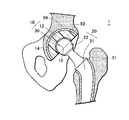
- FIG. 1 is a schematic diagram of an artificial hip joint according to a first embodiment of the present invention.
- FIG. 2 is a perspective view of an acetabular cup for the artificial hip joint according to a first embodiment of the present invention.
- FIG. 3 is a schematic diagram of a bipolar artificial hip joint according to a second embodiment of the present invention.
- FIG. 4 is a schematic diagram of an artificial shoulder joint according to a third embodiment of the present invention.
- FIG. 5 is a schematic diagram of an artificial vertebral joint according to a fourth embodiment of the present invention.
- FIG. 6 is a schematic diagram of an artificial knee joint according to a fifth embodiment of the present invention.
- FIG. 7 is a schematic diagram of an artificial elbow joint according to a sixth embodiment of the present invention.
- FIG. 8 is a schematic diagram of an artificial ankle joint according to a seventh embodiment of the present invention.
- FIG. 9 is a schematic diagram of an artificial finger joint according to an eighth embodiment of the present invention.
- FIG. 10 is a schematic diagram of a joint simulator wear test apparatus used in Examples of the present invention.
- FIG. 11 is a graph showing the result of a joint simulator wear test conducted on the acetabular cup according to Example 1 of the present invention.
- FIG. 12 is a graph showing the result of a joint simulator wear test conducted on the acetabular cup according to Example 1 of the present invention.
- FIG. 13 is a graph showing the results of a joint simulator wear test conducted on the acetabular cup according to Example 1 of the present invention.
- FIG. 14 (A to C) is a graph showing the results of a joint simulator wear test conducted on the acetabular cup according to Example 1 of the present invention.
- FIG. 15 is a graph showing the results of a joint simulator wear test conducted on the acetabular cup according to Example 1 of the present invention.
- FIG. 16 (A, B) is a graph showing the results of a joint simulator wear test conducted on the acetabular cup according to Example 2 of the present invention.
- FIG. 17 (A, B) is a graph showing the results of a joint simulator wear test conducted on the acetabular cup according to Example 2 of the present invention.
- FIG. 18 (A, B) is a graph showing the results of a joint simulator wear test conducted on the acetabular cup according to Example 2 of the present invention.
- FIG. 19A is a cross-sectional TEM image of the acetabular cup according to Example 3 of the present invention.
- FIG. 19B is a cross-sectional TEM image of the acetabular cup according to Example 3 of the present invention.
- FIG. 19C is a cross-sectional TEM image of the acetabular cup according to Example 3 of the present invention.
- FIG. 19D is a cross-sectional TEM image of the acetabular cup according to Example 3 of the present invention.
- FIG. 20 is a graph showing the measurement results of a static-water contact angle of the acetabular cup surface according to Example 4 of the present invention.
- FIG. 21 is a graph showing the measurement results of an atomic concentration of phosphorus atom and an atomic concentration of nitrogen atom of the acetabular cup surface according to Example 4 of the present invention.
- FIG. 22 is a graph showing the measurement results of an atomic concentration of phosphorus atom of an acetabular cup surface according to Example 5 of the present invention.
- FIG. 1 is a schematic diagram of an example of artificial joint, an artificial hip joint 1 .
- the artificial hip joint 1 is constituted from a bearing component (acetabular cup) 10 that is fixed onto acetabulum 94 of a hip bone 93 and a femoral stem 20 that is fixed onto a proximal end of a femur 91 .
- the acetabular cup 10 comprises a cup substrate 12 that has a substantially semi-spherical acetabulum fixing surface 14 and a bearing surface of concave semi-spherical shape, and a polymer layer 30 with which the sliding surface is covered.
- a bone head 22 of a femoral stem 20 is slidably fitted to a covered bearing surface 16 of the acetabular cup 10 , so as to function as a hip joint.
- the acetabular cup 10 of the present invention is constituted by graft-coating the bearing surface of the cup substrate 12 with a polymer layer 30 having a phosphorylcholine group.
- the polymer layer 30 has such a molecular structure as polymer chains having a phosphorylcholine group are orientational ordered along the surface. This structure resembles that of cell membrane.
- a biolayer that constitutes the cartilage surface of a joint in the living body is an aggregate of phospholipid molecules, and has microscopic surface structure of being covered with phosphorylcholine groups (Ishihara; Surgery, Vol. 61, p 122, 1999).
- the biolayer holds a lubricating liquid therein so as to constitute a lubricated joint surface having an extremely low friction coefficient.
- the polymer layer 30 of the present invention also has affinity with the lubricating liquid and is capable of holding the lubricating liquid therein similarly to the biolayer, so as to provide a lower friction coefficient than that of the covered sliding surface 16 of the acetabular cup 10 of the prior art.
- Tribological characteristic can be improved so as to provide higher wear-resistance by covering the bearing surface of the acetabular cup 10 with the polymer layer 30 having a phosphorylcholine group, as described above.
- the bearing component for artificial joint is required to maintain the high wear-resistance over a long period of time in such a harsh operating condition as sliding while supporting the entire body weight in the state of making contact with the body fluid. In other words, extremely high durability is required.
- the present inventors have studied the dependency of durability of the acetabular cup 10 on the thickness of the polymer layer 30 . It was found that excellent wear resistance is obtained when the thickness of the polymer layer is in a range from 10 to 200 nm. When the film thickness is less than 10 nm, durability deteriorates in a short period of time due to insufficient wear resistance. When the film thickness is larger than 200 nm, uniformity of the polymer layer 30 tends to deteriorate and the film may have portions where the film is thinner or missing. The polymer layer 30 may remove or the acetabular cup 10 may wear off in such portions, thus resulting in deterioration of wear resistance. Particularly preferable range of the thickness of the polymer layer 30 is in a range from 30 to 100 nm.
- density of the polymer layer means the number of 2-methacryloyloxyethyl phosphorylcholine (hereinafter referred to as MPC) polymer that exists in a unit area.
- MPC 2-methacryloyloxyethyl phosphorylcholine
- a phosphoric index is defined as the ratio I P /I M of peak intensity I P at 1080 m ⁇ 1 that is the absorption wavelength of a phosphate group to a peak intensity I M at 1,460 m ⁇ 1 that is the absorption wavelength of a methylene repeating unit in the spectrum of Fourier transform infrared spectroscopy (FT-IR).
- FT-IR Fourier transform infrared spectroscopy
- the cup substrate 12 made of a polymer material having a methylene repeating unit as in the present invention and FT-IR measurement is carried out, the absorption peak of methylene repeating unit due to the cup substrate 12 and the absorption peak of phosphate group due to the polymer layer 30 are observed.
- the cup substrate 12 is constant and the thickness of the polymer layer 30 does not undergo an excessive variation (for example, deviation in thickness remains within 1 ⁇ m)
- phosphoric index calculated from the two peak intensities is roughly proportional to a number of phosphate group s existing in unit area of the cup substrate 12 .
- the phosphoric index was used to evaluate the durability of the acetabular cup 10 provided with the polymer layer 30 having a phosphorylcholine group on the bearing surface. It was found that the acetabular cup having the polymer layer 30 of the thickness from 10 to 200 nm with phosphoric index not lower than 0.32 showed significantly higher durability than the acetabular cup of the prior art, and accelerated joint simulator wear test indicated durability of five years or more. Furthermore, experiments with acetabular cups having phosphoric index of 0.45 or higher exhibited durability of 10 years or more. These values of durability may be regarded as lifetime that is long enough to eliminate the need of revision surgery over lifetime for patients who receive joint arthroplasty at ages over a certain level.
- phosphoric index of the polymer layer 30 is preferably 0.32 or more, and more preferably 0.45 or more.
- the polymer layer 30 having high hydrophilicity is considered to show good compatibility with the lubricating liquid in the human body. Once fully impregnated with the lubricating liquid, the polymer layer 30 would enable the covered bearing surface 16 of the acetabular cup 10 to make smooth sliding motion, thereby improving the durability of the acetabular cup 10 .
- the hydrophilicity can be adjusted by controlling the density of the polymer layer 30 . Accordingly, the present inventors investigated the relationship between the phosphoric index and hydrophilicity and between durability and hydrophilicity. Hydrophilicity (static-water contact angle) is evaluated by the contact angle of the polymer layer 30 with a water droplet placed thereon.
- the polymer layer 30 having a phosphorylcholine group tends to show higher hydrophilicity and a smaller static-water contact angle when a phosphoric index increases. However, as the phosphoric index increases beyond 0.3, a contact angle takes a minimum value of 14° and do not decrease anymore when the phosphoric index is increased further.
- the accelerated joint simulator wear test produced the following findings.
- the polymer layer 30 showed static-water contact angle of 20° or less in terms of a static-water contact angle.
- the polymer layer 30 showed 14° or less static-water contact angle.
- durability of the acetabular cup can be improved so as to suppress wear debris from being generated over a long period of time, thereby providing an artificial joint that suppresses loosening from occurring and makes it possible for the number of replacement surgeries required for the artificial joint to be reduced or eliminated altogether.
- the bearing material of the present invention requires it to fix the polymer layer 30 to the bearing surface of the acetabular cup 10 . While several methods of fixing have been known, the present invention employs photoinduced graft polymerization by means of ultraviolet-ray irradiation. That is, the polymer layer 30 is fixed by bonding between a polymerizable monomer having a phosphorylcholine group and the bearing surface. This method has such advantages as the capability to modify only the bearing surface without causing the properties such as strength of the polymer material that constitute the acetabular cup 10 , chemical stability of the bond, and capability to form a large amount of a phosphorylcholine group on the bearing surface of the artificial joint replacement thereby increasing the density of the polymer layer 30 .
- a polymerizable monomer having a phosphorylcholine group is used for formation of a polymer layer 30 .
- the polymer layer 30 can be grafted from the bearing surface of the acetabular cup 10 by selecting a monomer having a phosphorylcholine group in the side chain and a functional group capable of graft-polymerizing with a polymer constituting the acetabular cup 10 in the main chain.
- Examples of the polymerizable monomer suited for use in the present invention include 2-methacryloyloxyethyl phosphorylcholine, 2-acryloyloxyethyl phosphorylcholine, 4-methacryloyloxybutyl phosphorylcholine, 6-methacryloyloxyhexyl phosphorylcholine, ⁇ -methacryloyloxyethylene phosphorylcholine and 4-styryloyloxybutyl phosphorylcholine.
- MPC is particularly preferable.
- An MPC monomer has a chemical structural formula shown below and includes a phosphorylcholine group and a polymerizable methacrylate unit.
- the MPC monomer has a feature that a high molecular weight MPC polymer can be easily prepared by radical polymerization (Ishihara et al.: Polymer Journal, Vol. 22, pp. 355 (1990). Therefore, when the polymer layer 30 is synthesized from the MPC monomer, grafting of the polymer layer 30 with the bearing surface can be conducted under comparatively mild conditions and also a large amount of graft polymers with a phosphorylcholine group can be formed on the bearing surface by forming the polymer layer 30 having high density.
- the polymer layer 30 that can be used in the present invention can also be formed from not only a homopolymer constituting a single polymerizable monomer having a phosphorylcholine group, but also a copolymer comprising a monomer having a phosphorylcholine group and the other vinyl compound. Thus, a function such as improved mechanical strength can be imparted to the polymer layer 30 .
- the cup substrate 12 of the acetabular cup 10 is made of a polymer material having a methylene repeating unit
- UHMWPE has particularly favorable mechanical properties such as wear resistance and deformation resistance, and is therefore suitable for the cup substrate 12 .
- CLPE made by a crosslinking treatment of UHMWPE has even more favorable mechanical properties than UHMWPE, and is more preferably used to form the cup substarte 12 of the acetabular cup 10 .
- the cup substrate 12 made of CLPE can be made by irradiating UHMWPE with high energy beams such as X-ray, electron beam or gamma-ray to apply a crosslinking treatment, and forming the material into a cup shape.
- the crosslinking treatment can also be conducted by using a crosslinking agent instead of the high energy ray, it is not practical in case safety of the crosslinking agent is not ensured when applied to a material used in the human body such as artificial joint.
- the crosslinking treatment by means of the high energy beam in contrast, can be done without compromising the safety of UHMWPE, and is preferably employed.
- the cup substrate 12 made of CLPE has free radicals generated when irradiated with high energy beam such as X-ray, electron beam or gamma-ray. Free radicals contained in the cup substrate 12 can act as an initiator for polymerization, during graft polymerization of a polymerizable monomer on the bearing surface of the cup substrate 12 , and therefore helps increase the density of the polymer layer 30 of the covered bearing surface 16 .
- reforming the cup substrate 12 as a whole into CLPE leads to an increase in the manufacturing cost. Therefore, it is also preferable to apply a crosslinking treatment only to the bearing surface of the cup substrate 12 to modify the surface region into CLPE, so as to use the cup substrate 12 having the covered bearing surface 16 of improved wear resistance in the acetabular cup 10 .
- the cup substrate 12 made of CLPE having such free radicals can be made by preparing the polymer material having a methylene repeating unit irradiated with high energy beam before the process of forming a cup substrate 12 in shape. Preparation of this polymer material involves a process of irradiating a polymer material having a methylene repeating unit with the high energy beam and a process of applying a heat treatment to the polymer material that has been irradiated with high energy ray at a temperature lower than a melting point thereof.
- the cup substrate 12 made of UHMWPE By irradiating the cup substrate 12 made of UHMWPE with high energy beam to generate a large amount of free radicals and then applying a heat treatment at a temperature lower than the melting point, most of the free radicals can be consumed in the C-C recombination and crosslinking bond while leaving a part of the free radicals to remain within the cup substrate 12 . It is not desirable to apply the heat treatment at a temperature higher than the melting point, which results in the consumption of substantially all of the free radicals.
- the acetabular cup 10 for the artificial hip joint of this embodiment can be manufactured by forming the polymer material having a methylene repeating unit (for example, UHMWPE) into shape of the cup substrate 12 by machining, then grafting the polymer layer 30 having a phosphorylcholine group from the bearing surface of the cup substrate 12 .
- a methylene repeating unit for example, UHMWPE
- a photoinduced polymerization initiator is applied to the bearing surface of the cup substrate 12 , the cup substrate 12 is immersed in a solution that contains polymerizable monomer having a phosphorylcholine group and, in this state, is irradiated on the bearing surface with ultraviolet light (having wavelength of, for example, from 300 to 400 nm).
- ultraviolet light having wavelength of, for example, from 300 to 400 nm.
- the thickness of the polymer layer 30 obtained as described above depends on the concentration of the monomer in the solution containing the polymerizable monomer, solution temperature, ultraviolet-ray irradiation time and the amount of free radicals contained in the cup substrate 12 .
- the polymer layer 30 having a desired thickness can be obtained by controlling these factors.
- the ultraviolet-ray irradiation time is preferably 40 minutes or more.
- the ultraviolet-ray irradiation time is preferably set to 40 minutes or more.
- monomer concentration of the solution may be controlled within a range from 0.25 to 0.5 mol/L.
- the monomer concentration is lower than 0.25 mol/L, not only the polymer layer 30 becomes too thin, but also density of the polymer layer 30 formed on the bearing surface of the acetabular cup 10 decreases.
- the monomer concentration is higher than 0.5 mol/L, the monomers polymerize with each other while being suspended in the solution, before reaching the bearing surface of the acetabular cup 10 .
- FIG. 3 shows another artificial hip joint, a bipolar artificial hip joint 40 .
- This artificial hip joint 40 is characterized by the constitution of the femoral head portion that comprises two components of a ball-shaped femoral head 22 and an outer head 42 that accommodates the femoral head 22 .
- the femoral head 22 consists of a ball-shaped component made of ceramics or a metal, and is fixed onto a stem body 21 at a proximate portion thereof.
- the outer head 42 is constituted from an outer shell 44 that is a semi-spherical hollow component made of a metal or ceramics, a liner substrate 46 made of UHMWPE fixed onto the inside of the outer shell 44 , and the polymer layer 30 fixed onto the spherical sliding surface that is formed in the liner substrate 46 .
- the liner substrate 46 and the polymer layer 30 constitute the bearing materials of the artificial joint.
- the polymer layer 30 is made of polymer chains having a phosphorylcholine group grafted on the sliding surface, similarly to the case of the first embodiment.
- the outer head 42 receives the femoral head 22 slidably to the covered sliding surface 16 of the liner substrate 46 , thereby forming a first bearing section.
- the outer head 42 itself is also accommodated into the acetabulum of the patient's bone to form a second bearing section.
- the bipolar artificial hip joint 40 is constituted so that the first bearing section and the second bearing section make sliding motions successively in accordance to the extent of movement of the hip joint.
- the first bearing section undergoes a first sliding motion and, when the movement of the hip joint goes beyond the movable range of the first bearing section, the second bearing section undergoes a second sliding motion.
- the first sliding motion is predominant and the first bearing section is subject to more wear.
- polymer layer 30 having a phosphorylcholine group is provided on the bearing surface of the liner substrate 46 of the outer head 42 , so as to improve the tribological characteristic of the first (covered) bearing section, thereby achieving higher wear-resistance and higher durability.
- FIG. 4 shows an artificial shoulder joint 70 that is constituted from a bearing component (glenoid cavity cup 15 ) that is fixed in the glenoid cavity of a shoulder blade and a humeral stem 25 that is fixed onto the humerus at the proximal end thereof.
- a bearing component glenoid cavity cup 15
- a humeral stem 25 that is fixed onto the humerus at the proximal end thereof.
- the humeral stem 25 is constituted from a stem body 26 that is inserted into bone marrow of the humerus, and a humeral head 27 made of a metal or ceramics in substantially semi-spherical shape that is fixed onto proximal end of the stem body 26 .
- the glenoid cavity cup 15 comprises a cup substrate 17 that has a shoulder blade stem 19 embedded in the glenoid cavity of a shoulder blade and a bearing surface formed in a shallow concave shape, and the polymer layer 30 formed to coat the bearing surface.
- the polymer layer 30 is made of polymer chains having a phosphorylcholine group grafted from the bearing surface.
- the artificial shoulder joint 70 functions as a shoulder joint that allows the arm to move back and forth and make swiveling motion, as the humeral head 27 of the humeral stem 25 is put into contact with the covered bearing surface 16 of the glenoid cavity cup 15 and is caused to make sliding motion.
- polymer layer 30 having a phosphorylcholine group is provided on the bearing surface of the cup substrate 17 , so as to improve the tribological characteristic of the bearing component, thereby achieving higher wear-resistance and higher durability.
- FIG. 5 shows an artificial vertebral joint 32 that is constituted from an upper component 33 and a lower component 34 that are fixed between two bodies of vertebra which sandwich an intervertebral disk.
- the lower component 34 is constituted from a convex sliding member 36 that ensures the sliding motion of the joint instead of the intervertebral disk, a metal casing 35 that accommodates the convex bearing component 36 and a stem 39 that protrudes from the bottom of the casing 35 and secures the lower component 34 onto the body of vertebra.
- the convex bearing component 36 has a disk-shaped base body 37 having a swell (bearing surface) at the center thereof, and the polymer layer 30 with which the bearing surface is covered.
- the polymer layer 30 is made of polymer chains having a phosphorylcholine group grafted from the bearing surface.
- the upper component 33 is made of a metal and has, on the bottom surface thereof, a concave receiving part 38 that slidably accommodates the covered bearing surface 16 of the convex bearing component 36 and, on the top surface thereof, the stem 39 that secures the upper component 33 onto the body of vertebra.
- the artificial vertebral joint 32 constitutes a part of the spine that is capable of bending in all directions, by putting the concave receiving part 38 of the upper component 33 into contact with the covered bearing surface 16 of the convex bearing component 36 so as to make sliding motion.
- the polymer layer 30 having a phosphorylcholine group is provided on the bearing surface of the convex bearing component 36 of the lower component 34 , so as to improve the tribological characteristic of the bearing component, thereby achieving higher wear resistance and higher durability.
- the artificial vertebral joint that suppresses wear debris from being generated and loosening from occurring over a long period of time, thereby reducing the number of revision surgeries required for the artificial vertebral joint or eliminating the need thereof altogether.
- FIG. 6 to FIG. 9 show artificial joints for replacement of joints that govern movements of mainly bending back and forth.
- Such artificial joints can be classified into hinged type that links two constituent members of the joint by means of a shaft, and non-hinged type that uses two constituent members of the joint which do not contact with each other.
- Hinged type artificial joints currently in use include artificial finger joints, artificial knee joints and artificial elbow joints, and unhinged type artificial joints include artificial knee joints, artificial elbow joints and artificial ankle joints.
- FIG. 6 shows an artificial knee joint 72 of unhinged type that is constituted from a tibial component 50 that is fixed onto a proximal portion of a tibia and a joint replacement (femoral component 52 ) that is made of a metal or ceramics and is fixed onto a distal portion of a femur, with these components being fixed onto respective apophysial portions while being separated from each other.
- a joint replacement femoral component 52
- the femoral component 52 has, on the bottom thereof, two curved protruding surfaces 53 , 53 (inner condyle and outer condyle) that extend in an arc shape from the front (knee cap side indicated by arrow A) toward the back (back of knee indicated by arrow P).
- the tibial component 50 of the artificial knee joint 72 is constituted from a bearing component (tibial tray 48 ) that forms the joint surface, and a tibial stem 51 that fixes the tibial tray 48 onto the tibia.
- the tibial tray 48 has curved recesses formed on the top surface thereof to extend from the front A toward the back P, the recesses serving as the covered bearing surfaces 16 , 16 that make contact with two protruding surfaces 53 , 53 of the femoral component 52 .
- the tibial tray 48 comprises a tray substrate 49 made of UHMWPE and the polymer layer 30 with which the bearing surfaces of the tray substrate 49 are covered.
- the polymer layer 30 is made of polymer chains having a phosphorylcholine group grafted from the bearing surface 16 .
- the artificial knee joint 72 of the fifth embodiment enables bending and extending motion in the anteroposterior direction by making sliding motion between the protruding surfaces 53 , 53 of the femoral component 52 and the covered bearing surfaces 16 , 16 of the tibial tray 48 .
- FIG. 7 shows an artificial elbow joint 74 of unhinged type, that is constituted from an ulnar component 58 to be fixed onto a proximal portion of ulna, and a joint replacement (humeral component 62 ) that is fixed onto a distal portion of the humerus, with these components being fixed onto respective apophysial portions while being separated from each other.
- the ulnar component 58 is constituted from a sliding member (ulnar tray 54 ) that constitutes the joint surface and an ulnar stem 60 that fixes the ulnar tray 54 onto the ulna.
- the ulnar tray 54 has a shape of an annular component a part of which is cut off in the radial direction, with the inner surface thereof serving as the covered bearing surface 16 .
- the bearing surface of the ulnar tray 54 forms a ridge 55 that rises from both edges toward the center in the direction of width and extends along the circumference.
- the ulnar tray 54 comprises a tray substrate 56 made of UHMWPE and the polymer layer 30 with which the bearing surfaces of the tray substrate 56 is graft-coated.
- the polymer layer 30 is made of polymer chains having a phosphorylcholine group grafted from the bearing surface.
- the humeral component 62 of the artificial elbow joint 74 is made of a metal or ceramics and has a substantially cylindrical shape with a part thereof being cut off. Circumference of the humeral component 62 is slightly recessed at the center so as to form a shape of pulley 63 .
- the pulley 63 of the humeral component 62 and the ridge 55 of the ulnar tray 54 are engaged with each other, so as to form an artificial elbow joint that is capable of bending and extending in the anteroposterior direction.
- FIG. 8 shows an artificial ankle joint (for left foot) of unhinged type, that is constituted from a tibial component 68 fixed onto a distal portion of the tibia and a joint replacement (ankle bone component 68 ) that is fixed onto a proximal portion of the ankle bone, with these components being fixed onto respective apophysial portions while being separated from each other.
- the tibial component 66 is constituted from a bearing component (tibial tray 64 ) that constitutes the joint surface and a tibial stem 67 that fixes the tibial tray 64 onto the tibia.
- the tibial tray 64 has a bottom surface formed into concave surface that warps from the front A toward the back P, the bottom surface serving as the covered bearing surface 16 .
- a flange 96 protrudes from the edge of inside M of the tibial tray 64 downward, so as to prevent the joint from displacing laterally into dislocation.
- the tibial tray 64 comprises a tray substrate 65 made of UHMWPE and the polymer layer 30 with which the bearing surfaces of the tray substrate 65 is graft-coated.
- the polymer layer 30 is made of polymer chains having a phosphorylcholine group grafted from the bearing surface.
- the ankle bone component 68 of the artificial foot joint 76 is made of a metal or ceramics and has a top surface formed in convex surface that warps from the front A toward the back P.
- the ankle bone component 68 is fixed onto a proximal portion of the ankle bone by inserting the ankle bone stem 98 formed on the bottom surface into the bone marrow of the ankle bone.
- the artificial foot joint that is capable of bending and extending in the anteroposterior direction is formed by putting the top surface of the ankle bone component 68 and the covered bearing surface 16 of the tibial tray 64 into slidable contact with each other.
- the polymer layer 30 having a phosphorylcholine group is provided on the bearing surface of the tray substrate so as to improve the tribological characteristic of the bearing component, thereby achieving higher wear-resistance and higher durability.
- the artificial joint that suppresses wear debris from being generated and loosening from occurring over a long period of time, thereby reducing the number of revision surgeries required for the artificial joint or eliminating the need thereof altogether.
- FIG. 9 shows artificial finger joint 80 of hinged type used in arthroplasty for a joint between os metacarpale and finger bone or a joint between finger bones.
- the artificial finger joint 80 is constituted from a shaft component 81 fixed onto apophysial portion of the finger bone located at the distal side of the joint, and a receptor component 85 fixed onto apophysial portion of the finger bone located at the proximal side of the joint.
- the shaft component 81 is integrally made of a metal or ceramics, and has a shaft part 82 that protrudes on both ends 84 , 84 and a stem 83 that extends from the center of the shaft part 82 for fixing the shaft part 82 onto apophysial portion.
- a bearing component 85 of the artificial finger joint 80 comprises a bearing component 86 having two bearing holes 88 , 88 where the ends of the shaft part are to be fitted in, and a stem 87 for fixing the bearing component 86 onto apophysial portion.
- the bearing component 86 comprises a bearing substrate 89 made of UHMWPE and the polymer layer 30 with which the covered bearing surfaces 16 of the bearing holes 88 is covered.
- the polymer layer 30 is made of polymer chains having a phosphorylcholine group grafted from the bearing surface.
- a hinge structure is formed by fitting the ends 84 of the shaft part 82 into the bearing holes 88 of the bearing component 85 .
- the shaft part 82 rotates in the bearing holes 88 so that the artificial finger joint 80 can bend and extend.
- the polymer layer 30 having a phosphorylcholine group is provided on the bearing surface of the bearing holes 88 so as to improve the tribological characteristic of the hinge structure, thereby achieving higher wear-resistance and higher durability.
- the artificial finger joint that suppresses wear debris from being generated and loosening from occurring over a long period of time, thereby reducing the number of revision surgeries required for the artificial finger joint or eliminating the need thereof altogether.
- the acetabular cup 10 for the artificial hip joint shown in FIG. 1 and FIG. 2 was made, and hydrophilicity, phosphoric index and durability (period over which wear resistance can be maintained) were evaluated.
- the cup substrate 12 of the acetabular cup 10 was made of CLPE, and samples a to g were made.
- samples b to g graft-coated with the polymer layer 30 were made are described below. Sample a was made without the polymer layer 30 formed thereon for the purpose of comparison.
- Sample b was made by the following process.
- Step 1 A cup substrate 12 of the acetabular cup 10 immersed in an acetone solution of benzophenone (concentration of 10 mg/mL) for 30 seconds was pulled out of the solution and the solvent was removed from the surface of the cup substrate 12 .
- Step 2 With the cup substrate 12 being immersed in a aqueous solution of MPC (monomer concentration of 0.5 mol/L and solution temperature of 60° C.), the bearing surface of the cup substrate 12 was irradiated with ultraviolet light (wavelength of 300 to 400 nm) for 25 minutes thereby forming a polymer layer (MPC polymer) 30 grafted from the bearing surface.
- Step 3 The cup substrate 12 was taken out of the MPC solution and was sufficiently washed with pure water.
- Sample c was made in the same manner as in sample b, except for changing the ultraviolet-ray irradiation time to 50 minutes in the step 2.
- Sample d was made in the same manner as in sample b, except for changing the ultraviolet-ray irradiation time to 90 minutes in the step 2.
- Sample e was made in the same manner as in sample b, except for changing the ultraviolet-ray irradiation time to 180 minutes in the step 2.
- Sample f was made in the same manner as in sample d, except for changing the monomer concentration in the MPC solution to 0.25 mol/L.
- Sample g was made in the same manner as in sample d, except for changing the monomer concentration in the MPC solution to 1.00 mol/L and ultraviolet-ray irradiation time in the step 2 to 90 minutes.
- An accelerated joint simulator wear test was conducted in an environment mimicking the operating conditions in the human body, by forcibly sliding the acetabular cup of sample a to g and the artificial femoral head with each other.
- FIG. 10 is a schematic side view of the wear test apparatus 100 that has a container 102 which stores a body fluid-like lubricant and is connected in a slanted state (for example, at an angle of 45°) to a motor 106 .
- the container 102 has, on the bottom thereof, a holder 104 that holds the acetabular cup 10 .
- a femoral head mounting spindle 108 having the femoral head mounted on the distal end thereof disposed above the container 102 , so as to be capable of applying a load F downward on the femoral head 22 that is fitted into the covered bearing surface 16 of the acetabular cup 10 .
- the acetabular cup 10 and the femoral head 22 were immersed in 25% bovine serum 110 containing 0.1% sodium azide and 20 mM trisodium ethylenediaminetetraacetate.
- the femoral head 22 was made of a commercially available cobalt chromium alloy (26 mm in diameter).
- the test simulated the state of walking under Double Peak Paul conditions involving two peaks of 183 kg and 280 kg in one walking cycle per second.
- the bovine serum 110 was renewed every 500,000 cycles.
- the graphs shown in FIG. 11 and FIG. 12 include negative values for the weight change. This means a weight increase resulting from absorption of water by the MPC polymer layer 30 and the cup substrate 12 that constitute the sample. In this example, a negative value of weight change (an increase in weight) is interpreted to represent zero wear.
- FIG. 11 shows the test results of up to 5,000,000 cycles.
- Samples b to g that were graft-coated with the MPC polymer layer showed no significant increase in wear until about 2,500,000 cycles, thus exhibiting satisfactory wear resistance.
- wear on sample b increased suddenly, eventually reaching a level comparable to that of sample a (no MPC polymer layer provided) around 4,000,000 cycles and exceeding the wear of sample a beyond 4,500,000 cycles.
- Wear on sample g showed sudden increase beyond 3,500,000 cycles, a longer period than in the case of sample b, and thereafter showed wear at a rate comparable to that of sample a.
- FIG. 12 shows the test results of up to 10,000,000 cycles on samples a, c and d.
- Sample a no MPC polymer layer provided
- Sample c showed extremely low wear until about 8,000,000 cycles, thus exhibiting excellent wear-resistance.
- Sample d showed no significant increase in wear until about 10,000,000 cycles, thus exhibiting excellent durability resistance and the ability to maintain wear resistance comparable to that at the start of use over a long period of time.
- wear rate (mg/1,000,000 cycles) plotted along the ordinate means the weight loss (mg) of the acetabular cup caused by wear during a period of 1,000,000 cycles.
- wear rate at 10,000,000 cycles means the weight loss of the acetabular cup caused by wear during a period from 9,000,000 cycles to 10,000,000 cycles.
- 1,000,000 cycles in the accelerated joint simulator wear test is equivalent to one year of use, and therefore the wear rate gives the amount of wear debris that is expected to be generated in one year.
- the acetabular cup made of UHMWPE shows wear rate of 10 to 20 mg/1,000,000 cycles
- the acetabular cup made of CLPE shows wear rate of 3 to 5 mg/1,000,000 cycles.
- upper limit of wear rate is set at 1 mg/1,000,000 cycles in order to clarify the range where the wear rate can be kept at a very low level.
- the graph of FIG. 13 shows the wear rate of the cup after undergoing 2,500,000 cycles of sliding motion (equivalent to about 3 years of use).
- wear rate is plotted against the ultraviolet-ray irradiation time (polymerization time).
- wear rate is plotted against the static-water contact angle.
- wear rate is plotted against the phosphoric index.
- the acetabular cup 10 can maintain satisfactory wear resistance after about three years of use when the bearing surface is graft-coated with MPC polymer layer that is treated with ultraviolet-ray irradiation for 25 minutes or more and the covered bearing surface 16 has static-water contact angle of 50° or less and phosphoric index of 0.15 or higher.
- wear rate of the acetabular cup 10 showed a trend of monotonous increase or decrease with respect to the three parameters of ultraviolet-ray irradiation time, static-water contact angle and phosphoric index.
- the graph of FIG. 14 shows the wear rate of the cup after undergoing 5,000,000 cycles of sliding motion (equivalent to about 5 years of use).
- wear rate is plotted against the ultraviolet-ray irradiation time (polymerization time).
- wear rate is plotted against the static-water contact angle.
- wear rate is plotted against the phosphoric index.
- the acetabular cup 10 can maintain satisfactory wear resistance after about five years of use when the bearing surface is graft-coated with MPC polymer layer formed by ultraviolet-ray irradiation for a period of 40 minutes or more and the covered bearing surface 16 has a contact angle of 20° or less with water and a phosphoric index of 0.28 or more.
- the graph of FIG. 15 shows the wear rate of the cup after undergoing 10,000,000 cycles of sliding motion (equivalent to about 10 years of use).
- wear rate is plotted against the ultraviolet-ray irradiation time (polymerization time).
- wear rate is plotted against the static-water contact angle.
- wear rate is plotted against the phosphoric index.
- the acetabular cup 10 can maintain satisfactory wear resistance after about ten years of use when the bearing surface is graft-coated with MPC polymer layer that is formed with ultraviolet-ray irradiation for a period of 90 minutes or more and the covered bearing surface 16 has static-water contact angle of 14° or less and a phosphoric index of 0.45 or more.
- wear rate of sample c When subjected to 10,000,000 cycles of test, wear rate of sample c (with MPC polymer layer having phosphoric index of 0.32) decreased to a level comparable to the wear rate of sample a (without MPC polymer layer).
- the acetabular cup having the MPC polymer layer formed thereon exhibits satisfactory wear resistance regardless of the density of the polymer layer for about three years of use, although MPC polymer layer having low density may not be capable of rendering sufficient durability to the acetabular cup after five years of use.
- sample X Wear resistance of an acetabular cup (called sample X) made under the manufacturing conditions disclosed in Japanese Patent Unexamined Publication (Kokai) No. 2003-310649 was estimated and plotted as point X in FIGS. 13 to 15 .
- Sample X was made in the same manner as in sample b, except for changing the ultraviolet-ray irradiation time to 30 minutes in the step 2.
- Wear resistance of sample X remains within the permissible range up to 2,500,000 cycles but deviates beyond the permissible range as the use is elongated up to 5,000,000 cycles and decreases to a level of about the same level as that of sample a with no MPC polymer layer at 10,000,000 cycles.
- the atomic concentrations (atom %) of phosphorus atom and nitrogen atom of the covered bearing surface were measured on samples a to e made in this Example as the indirect indication of density of the MPC polymer layer provided on the bearing surface, to investigate the relationship between the atomic concentrations and durability of the sample.
- one molecule of the MPC monomer includes one phosphorus atom and one nitrogen atom. Therefore, proportions of phosphorus atoms and nitrogen atoms included in the measurement region (equivalent to atomic concentrations) are in proportion to the ratio of MPC molecules that exist in the region. This means that atomic concentrations of phosphorus atom and nitrogen atom can be used as the indicators of the density of the MPC polymer layer.
- XPS measurement has far higher spatial resolution than the FT-IR employed in Example 1, and therefore has the advantage of the capability to measure even a sample surface that has irregularities.
- XPS measurement covers only a small surface area, result of the measurement may greatly vary depending on the point of measurement, when the MPC polymer layer is not uniform. Accordingly, it is preferable to make XPS measurement at plurality of points and average the results.
- XPS measurement was conducted by using Mg-K ⁇ line as the X-ray with an excitation voltage of 15 kV and take-off angle of 90°.
- the XPS spectrum thus obtained was used to determine the atomic concentration of phosphorus atom and atomic concentration of nitrogen atom. Atomic concentration will be given in terms of atom %.
- FIGS. 16 to 18 Relationships between the atomic concentration and wear resistance (wear rate) derived from the results shown in Table 2 and the results of wear test of Example 1 are shown in FIGS. 16 to 18 . Points a to e in the graph represent the test results of samples a to e, respectively.
- the graph of FIG. 16 shows wear rate of the cup after 2,500,000 cycles of sliding motion (equivalent to about three years of use).
- the graph of FIG. 17 shows wear rate of the cup after 5,000,000 cycles of sliding motion (equivalent to about five years of use).
- the graph of FIG. 18 shows wear rate of the cup after 10,000,000 cycles of sliding motion (equivalent to about ten years of use).
- FIG. 16(A) , FIG. 17(A) and FIG. 18(A) are graphs of wear rate plotted against the atomic concentration of phosphorus atom.
- FIG. 16(B) , FIG. 17(B) and FIG. 18(B) are graphs of wear rate plotted against the atomic concentration of nitrogen atom.
- upper limit of wear rate was set at 1 mg/1,000,000 cycles, and accordingly the threshold of operation cycles was determined.
- sample b having MPC polymer layer of atomic concentration of phosphorus atom 2.65 atom %, atomic concentration of nitrogen atom 1.86 atom %) showed wear rate larger than that of sample a (MPC polymer layer).
- the acetabular cup having the MPC polymer layer formed thereon exhibits higher wear-resistance regardless of the density of the polymer layer for about three years of use, although MPC polymer layer having low density may not be capable of rendering sufficient durability to the acetabular cup after five years of use.
- Thickness of the MPC polymer layer, with which the bearing surface of the acetabular cup is graft-coated, was measured on samples a, d, f and f made in Example 1.
- Sample was enclosed by epoxy resin, dyed with ruthenium tetrachloride and was cut into ultra-thin slice by using an ultra-microtome. The slice was observed under a transmission electron microscope (TEM) JEM-1010 of JEOL, Ltd. with acceleration voltage of 100 kV.
- TEM transmission electron microscope
- FIG. 19A shows sample that was not covered with MPC polymer layer.
- FIG. 19B shows sample f (monomer concentration 0.25 mg/L).
- FIG. 19C shows sample d (monomer concentration 0.50 mg/L).
- FIG. 19D shows sample g (monomer concentration 1.00 mg/L).
- FIGS. 19B to 19D showed a graft-coated layer (MPC polymer layer) not shown in FIG. 19A .
- layer thickness is from 10 to 30 nm
- layer thickness is from 100 to 200 nm.
- FIG. 19D in contrast, MPC polymer layer with thickness from 200 to 250 nm is formed, although observation at various points showed that there are points where the layer is hardly formed, the so-called pin holes.
- the bearing surface is irradiated with ultraviolet light, benzophenone existing on the bearing surface is activated, and polyethylene existing on the bearing surface is then activated.
- An MPC monomer contained in the monomer solution reacts with the activated polyethylene and is grafted from the bearing surface. If the graft polymerization proceeds properly, density of the MPC polymer increases. Then MPC monomer contained in the monomer solution continues to polymerize with the MPC polymer grafted from the bearing surface so that the MPC polymer chain becomes longer, thus resulting in the growth of the film thickness.
- graft polymerization proceeds properly.
- the monomer concentration in the monomer solution is as high as 1.0 mg/L, however, the MPC monomer irradiated with ultraviolet light reacts with MPC monomer located nearby, before reaching the bearing surface, thus forming MPC polymer in the solution.
- This MPC polymer is not bonded with the bearing surface, and is therefore taken away from the acetabular cup when washed. Since the formation of this MPC polymer causes the MPC monomer concentration to decrease rapidly in the solution nearby, local regions of low monomer concentration are generated which, if the monomer concentration is too low, make it impossible to form the MPC polymer layer and result in pin holes.
- uniform MPC polymer layer cannot be formed when the concentration of the MPC monomer solution is too low or too high, thus resulting in lower durability of the acetabular cup.
- a static-water contact angle (indicator of hydrophilicity) of the MPC polymer layer 30 was measured on a plurality of samples formed with various monomer concentrations, with the results shown in FIG. 20 .
- Points a, d, f and g in the graph represent the test results of samples a, d, f and g, respectively, of Example 1.
- contact angle showed the lowest (14°) when the monomer concentration was 0.50 mg/L, and remained at low levels of 20° or less when the monomer concentration was in a range from 0.25 mg/L to 0.50 mg/L. When the monomer concentration deviates from this range, the contact angle increases.
- the contact angle is considered to increase due to low density of MPC polymer layer and thin polymer layer.
- MPC polymer layer becomes thicker but pin holes are more likely to be produced at points where the MPC polymer layer has lower density, thus resulting in higher contact angle.
- Atomic concentration of phosphorus atom and atomic concentration of nitrogen atom were measured by XPS analysis on various samples of different monomer concentrations, with the results shown in FIG. 21 .
- Points a, d, f and g in the graph represent the test results of samples a, d, f and g, respectively, of Example 1.
- FIG. 21 it can be seen that atomic concentration of phosphorus atom (graph P) and atomic concentration of nitrogen atom (graph N) have similar tendencies.
- Atomic concentration of phosphorus atom and atomic concentration of nitrogen atom show the highest values when the monomer concentration is 0.5 mg/L. In the range of the monomer concentration from 0.25 to 0.50 mg/L where good hydrophilicity was obtained, atomic concentration of phosphorus atom was 4.3 atom % or higher and atomic concentration of nitrogen atom was 3.9 atom % or higher.
- the atomic concentration of phosphorus atom increased roughly in proportion to the ultraviolet-ray irradiation time till 50 minutes where it stopped increasing. Thus it is supposed that formation of the MPC polymer layer is mostly completed with ultraviolet-ray irradiation of 50 minutes, regardless of the monomer concentration.
- the monomer concentration is high, in particular, increasing rate of atomic concentration of phosphorus atom due to the ultraviolet-ray irradiation beyond the period of 50 minutes is lower than that of a case of lower monomer concentration, thus showing that the effect of ultraviolet-ray irradiation on the atomic concentration of phosphorus atom saturates at around 50 minutes.
- Example 1 it is preferable to set the ultraviolet-ray irradiation time to 40 minutes or more when the monomer concentration is 0.50 mol/L. For all values of the monomer concentration, it is preferable to irradiate with ultraviolet light for 50 minutes or more.
Abstract
Description
- 1 Artificial hip joint
- 10 Acetabular cup
- 12 Cup substrate
- 15 Glenoid cavity cup
- 16 Covered sliding surface
- 20 Femoral stem
- 22 Femoral head
- 27 Humeral head
- 30 Polymer layer
- 32 Artificial vertebral joint
- 33 Upper component
- 36 Convex bearing component
- 40 Bipolar femoral head
- 46 Liner substrate
- 48 Tibial tray
- 52 Femoral component
- 54 Ulnar tray
- 62 Humeral component
- 64 Tibial tray
- 68 Ankle bone component
- 70 Artificial shoulder joint
- 72 Artificial knee joint
- 74 Artificial elbow joint
- 76 Artificial ankle joint
- 80 Artificial finger joint
- 82 Shaft part
- 86 Bearing component

Step 3: The
Preparation of Sample c
| TABLE 1 | ||||
| Monomer | Ultraviolet-ray | static-water | ||
| Sample | concentration | irradiation time | contact angle | Phosphoric |
| No. | (mol/L) | (minutes) | (degrees) | index |
| Sample a | 0 | 0 | 89 | 0 |
| Sample b | 0.50 | 25 | 51 | 0.1 |
| Sample c | 0.50 | 50 | 14 | 0.32 |
| Sample d | 0.50 | 90 | 14 | 0.46 |
| Sample e | 0.50 | 180 | 14 | 0.48 |
| Sample f | 0.25 | 90 | 20 | 0.45 |
| Sample g | 1.00 | 90 | 48 | 0.35 |
Accelerated Joint Simulator Wear Test
| TABLE 2 | ||
| Atomic concentration of | Atomic concentration of | |
| Sample No. | phosphorus atom (atom %) | nitrogen atom (atom %) |
| Sample a | 0.00 | 0.0 |
| Sample b | 2.65 | 1.88 |
| Sample c | 5.29 | 4.10 |
| Sample d | 5.18 | 4.47 |
| Sample e | 5.54 | 4.59 |
Claims (24)
Applications Claiming Priority (5)
| Application Number | Priority Date | Filing Date | Title |
|---|---|---|---|
| JP2006-028529 | 2006-02-06 | ||
| JP2006028529A JP4963838B2 (en) | 2006-02-06 | 2006-02-06 | Low wear sliding member and artificial joint using the same |
| JP2006338601A JP5028080B2 (en) | 2006-12-15 | 2006-12-15 | Low wear sliding member and artificial joint using the same |
| JP2006-338601 | 2006-12-15 | ||
| PCT/JP2007/051923 WO2007091521A1 (en) | 2006-02-06 | 2007-02-05 | Low-wear sliding member and artificial joint making use of the same |
Publications (2)
| Publication Number | Publication Date |
|---|---|
| US20090306781A1 US20090306781A1 (en) | 2009-12-10 |
| US9044323B2 true US9044323B2 (en) | 2015-06-02 |
Family
ID=38345119
Family Applications (1)
| Application Number | Title | Priority Date | Filing Date |
|---|---|---|---|
| US12/223,669 Active 2030-05-24 US9044323B2 (en) | 2006-02-06 | 2007-02-05 | High wear-resistant bearing material and artificial joint replacement using the same |
Country Status (3)
| Country | Link |
|---|---|
| US (1) | US9044323B2 (en) |
| EP (1) | EP1987849B1 (en) |
| WO (1) | WO2007091521A1 (en) |
Cited By (2)
| Publication number | Priority date | Publication date | Assignee | Title |
|---|---|---|---|---|
| US20210282931A1 (en) * | 2018-05-07 | 2021-09-16 | Ceramtec Gmbh | Implant for use in a wear couple including a spherical wear partner |
| US11951011B2 (en) * | 2019-03-01 | 2024-04-09 | Giles | Line of dual mobility joint implant systems |
Families Citing this family (18)
| Publication number | Priority date | Publication date | Assignee | Title |
|---|---|---|---|---|
| EP1987849B1 (en) * | 2006-02-06 | 2016-11-23 | Kyocera Medical Corporation | Low-wear sliding member and artificial joint making use of the same |
| WO2009044816A1 (en) * | 2007-10-03 | 2009-04-09 | Japan Medical Materials Corporation | Biocompatible and low-wear material, artificial joint using the same and method of producing the same |
| WO2010058848A1 (en) | 2008-11-21 | 2010-05-27 | 日本メディカルマテリアル株式会社 | Graft polymerization method and product obtained thereby |
| JP5775694B2 (en) * | 2008-12-25 | 2015-09-09 | 京セラメディカル株式会社 | Polymer sliding material, artificial joint member, medical instrument and method for manufacturing the same |
| US20120197407A1 (en) * | 2009-08-20 | 2012-08-02 | The University Of Tokyo | Highly lubricating sliding member and artifical joint using same |
| US9132209B2 (en) | 2010-05-07 | 2015-09-15 | Howmedia Osteonics Corp. | Surface crosslinked polyethylene |
| US8840673B2 (en) * | 2011-09-21 | 2014-09-23 | Linares Medical Devices, Llc | Implantable elbow joint assembly with spherical inter-support |
| JP6061670B2 (en) * | 2012-12-27 | 2017-01-18 | 京セラメディカル株式会社 | Method for manufacturing sliding member for artificial joint and sliding member for artificial joint |
| JP6192362B2 (en) * | 2012-05-31 | 2017-09-06 | 京セラ株式会社 | Sliding member and manufacturing method thereof |
| EP2856978B8 (en) * | 2012-05-31 | 2017-12-13 | KYOCERA Corporation | Liner for implant material and method for producing same |
| JP5936566B2 (en) * | 2013-02-28 | 2016-06-22 | 京セラメディカル株式会社 | Manufacturing method of sliding member |
| EP2759280A1 (en) * | 2013-01-25 | 2014-07-30 | McMinn, Derek James Wallace | Prosthesis Having a Large Femoral Head |
| EP3071236A4 (en) | 2013-11-20 | 2017-05-24 | Trustees of Boston University | Injectable tissue supplement |
| DK3769724T3 (en) | 2017-09-22 | 2022-05-30 | Encore Medical L P Dba Djo Surgical | TALUS ANKLE IMPLANT |
| EP3501432A1 (en) | 2017-12-20 | 2019-06-26 | Stryker European Holdings I, LLC | Joint instrumentation |
| US11478819B2 (en) * | 2019-08-02 | 2022-10-25 | King Fahd University Of Petroleum And Minerals | Method for forming a polyethylene alumina nanocomposite coating |
| CN113995886B (en) * | 2021-10-28 | 2023-05-16 | 苏州微创关节医疗科技有限公司 | Artificial joint member, preparation method thereof and friction pair |
| CN114209473A (en) * | 2021-11-22 | 2022-03-22 | 苏州微创关节医疗科技有限公司 | Joint friction pair and joint prosthesis |
Citations (15)
| Publication number | Priority date | Publication date | Assignee | Title |
|---|---|---|---|---|
| US3990118A (en) * | 1974-10-31 | 1976-11-09 | Bio-Dynamics, Inc. | Joint prosthesis |
| US4059854A (en) * | 1977-01-03 | 1977-11-29 | Laure Prosthetics, Inc. | Ribbed finger joint implant |
| WO1997029793A1 (en) | 1996-02-13 | 1997-08-21 | Massachusetts Institute Of Technology | Radiation and melt treated ultra high molecular weight polyethylene prosthetic devices |
| US5879400A (en) | 1996-02-13 | 1999-03-09 | Massachusetts Institute Of Technology | Melt-irradiated ultra high molecular weight polyethylene prosthetic devices |
| JP2984203B2 (en) | 1995-10-31 | 1999-11-29 | 京セラ株式会社 | Manufacturing method of sliding member for artificial joint |
| WO2001005855A1 (en) | 1999-07-14 | 2001-01-25 | Nof Corporation | Random copolymer, process for the production thereof and medical material |
| US6228900B1 (en) | 1996-07-09 | 2001-05-08 | The Orthopaedic Hospital And University Of Southern California | Crosslinking of polyethylene for low wear using radiation and thermal treatments |
| US20020007219A1 (en) | 1996-02-13 | 2002-01-17 | Merrill Edward W. | Radiation and melt treated ultra high molecular weight polyethylene prosthetic devices |
| EP1206946A1 (en) | 1999-07-28 | 2002-05-22 | Nof Corporation | Medical materials and process for producing the same |
| US20020156536A1 (en) | 1996-02-13 | 2002-10-24 | Harris William H. | Polyethylene hip joint prosthesis with extended range of motion |
| WO2003070289A1 (en) | 2002-02-19 | 2003-08-28 | Kabushiki Kaisha Kobe Seiko Sho | Artificial joint member made of polymeric material |
| JP2003310649A (en) | 2002-02-19 | 2003-11-05 | Kobe Steel Ltd | Artificial joint member made of high polymer material |
| US20050165495A1 (en) | 1996-02-13 | 2005-07-28 | The General Hospital Corporation | Radiation melt treated ultra high molecular weight polyethylene prosthetic devices |
| JP2005237629A (en) | 2004-02-26 | 2005-09-08 | Kyocera Corp | Artificial joint and manufacturing method of the same |
| US20090306781A1 (en) * | 2006-02-06 | 2009-12-10 | Masayuki Kyomoto | High Wear-Resistant Bearing Material and Artificial Joint Replacement Using the Same |
-
2007
- 2007-02-05 EP EP07708041.4A patent/EP1987849B1/en active Active
- 2007-02-05 US US12/223,669 patent/US9044323B2/en active Active
- 2007-02-05 WO PCT/JP2007/051923 patent/WO2007091521A1/en active Application Filing
Patent Citations (34)
| Publication number | Priority date | Publication date | Assignee | Title |
|---|---|---|---|---|
| US3990118A (en) * | 1974-10-31 | 1976-11-09 | Bio-Dynamics, Inc. | Joint prosthesis |
| US4059854A (en) * | 1977-01-03 | 1977-11-29 | Laure Prosthetics, Inc. | Ribbed finger joint implant |
| JP2984203B2 (en) | 1995-10-31 | 1999-11-29 | 京セラ株式会社 | Manufacturing method of sliding member for artificial joint |
| US20050006821A1 (en) | 1996-02-13 | 2005-01-13 | The General Hospital Corporation | Radiation and melt treated ultra high molecular weight polyethylene prosthetic devices |
| US20050010288A1 (en) | 1996-02-13 | 2005-01-13 | Merrill Edward W. | Radiation and melt treated ultra high molecular weight polyethylene prosthetic devices |
| US20090105364A1 (en) | 1996-02-13 | 2009-04-23 | The General Hospital Corporation | Radiation and melt treated ultra high molecular weight polyethylene prosthetic devices |
| US20050267594A1 (en) | 1996-02-13 | 2005-12-01 | The General Hospital Corporation | Radiation and melt treated ultra high molecular weight polyethylene prosthetic devices |
| US20020007219A1 (en) | 1996-02-13 | 2002-01-17 | Merrill Edward W. | Radiation and melt treated ultra high molecular weight polyethylene prosthetic devices |
| US20050165495A1 (en) | 1996-02-13 | 2005-07-28 | The General Hospital Corporation | Radiation melt treated ultra high molecular weight polyethylene prosthetic devices |
| US20050096749A1 (en) | 1996-02-13 | 2005-05-05 | The General Hospital Corporation | Radiation and melt treated ultra high molecular weight polyethylene prosthetic devices |
| US6464926B1 (en) | 1996-02-13 | 2002-10-15 | The General Hospital Corporation | Process of making ultra high molecular weight polyethylene prosthetic devices |
| US20020156536A1 (en) | 1996-02-13 | 2002-10-24 | Harris William H. | Polyethylene hip joint prosthesis with extended range of motion |
| US20030013781A1 (en) | 1996-02-13 | 2003-01-16 | Merrill Edward W. | Radiation and melt treated ultra high molecular weight polyethylene prosthetic device |
| US20030105182A1 (en) | 1996-02-13 | 2003-06-05 | Merrill Edward W. | Radiation and melt treated ultra high molecular weight polyethylene prosthetic devices |
| US20030119935A1 (en) | 1996-02-13 | 2003-06-26 | Merrill Edward W. | Radiation and melt treated ultra high molecular weight polyethylene prosthetic devices |
| US20050056971A1 (en) | 1996-02-13 | 2005-03-17 | Merrill Edward W. | Radiation and melt treated ultra high molecular weight polyethylene prosthetic devices |
| US6641617B1 (en) | 1996-02-13 | 2003-11-04 | The General Hospital Corp. | Radiation and melt treated ultra high molecular weight polyethylene prosthetic device and method |
| WO1997029793A1 (en) | 1996-02-13 | 1997-08-21 | Massachusetts Institute Of Technology | Radiation and melt treated ultra high molecular weight polyethylene prosthetic devices |
| US6786933B2 (en) | 1996-02-13 | 2004-09-07 | The General Hospital Corporation | Radiation and melt treated ultra high molecular weight polyethylene prosthetic devices |
| US5879400A (en) | 1996-02-13 | 1999-03-09 | Massachusetts Institute Of Technology | Melt-irradiated ultra high molecular weight polyethylene prosthetic devices |
| US20040132856A1 (en) | 1996-02-13 | 2004-07-08 | Merrill Edward W. | Radiation and melt treated ultra high molecular weight polyethylene prosthetic devices |
| US6228900B1 (en) | 1996-07-09 | 2001-05-08 | The Orthopaedic Hospital And University Of Southern California | Crosslinking of polyethylene for low wear using radiation and thermal treatments |
| US6653423B1 (en) | 1999-07-14 | 2003-11-25 | Nof Corporation | Random copolymers, process for the production thereof and medical material |
| EP1211268A1 (en) | 1999-07-14 | 2002-06-05 | Nof Corporation | Random copolymer, process for the production thereof and medical material |
| WO2001005855A1 (en) | 1999-07-14 | 2001-01-25 | Nof Corporation | Random copolymer, process for the production thereof and medical material |
| EP1206946A1 (en) | 1999-07-28 | 2002-05-22 | Nof Corporation | Medical materials and process for producing the same |
| US6828028B1 (en) | 1999-07-28 | 2004-12-07 | Nof Corporation | Medical materials and process for producing the same |
| US7785372B2 (en) * | 2002-02-19 | 2010-08-31 | Kabushiki Kaisha Kobe Seiko Sho | Artificial joint member with grafted polymer surface |
| WO2003070289A1 (en) | 2002-02-19 | 2003-08-28 | Kabushiki Kaisha Kobe Seiko Sho | Artificial joint member made of polymeric material |
| EP1433488A1 (en) | 2002-02-19 | 2004-06-30 | Kabushiki Kaisha Kobe Seiko Sho | Artificial joint member made of polymeric material |
| JP2003310649A (en) | 2002-02-19 | 2003-11-05 | Kobe Steel Ltd | Artificial joint member made of high polymer material |
| US20040243249A1 (en) | 2002-02-19 | 2004-12-02 | Kazuhiko Ishihara | Artificial joint member made of polymeric material |
| JP2005237629A (en) | 2004-02-26 | 2005-09-08 | Kyocera Corp | Artificial joint and manufacturing method of the same |
| US20090306781A1 (en) * | 2006-02-06 | 2009-12-10 | Masayuki Kyomoto | High Wear-Resistant Bearing Material and Artificial Joint Replacement Using the Same |
Non-Patent Citations (12)
| Title |
|---|
| International Preliminary Report on Patentability issued Oct. 9, 2008 in the International (PCT) Application of which the present application is the U.S. National Stage (in English). |
| International Search Report issued Mar. 20, 2007 in the International (PCT) Application of which the present application is the U.S. National Stage (in English). |
| K. Ishihara et al, "Photoinduced graft polymerization of 2-methacryloyloxyethyl phosporylcholine on polyethylene membrane surface for obtaining blood cell adhesion resistance", Colloids and Surfaces. B, Biointerfaces, 2000, vol. 18, pp. 325-335. |
| Kazuhiko Ishihara et al., "Jinko saibomaku hyomen kochiku ni yoru chokino jinko kansetsu no kaihatsu," Materials Science and Technology, 2005, vol. 142, No. 4, pp. 178-182 (with partial English translation). |
| Toru Moro et al., "Polyethylene liner hyomen no MPC shori wa jinko kokansetsu no yurumi wo yokusei suru: nano-hyomen seigyo ni yoru chojumyo jinko kokansetsu no kaihatsu," Hip Joint, 2005, vol. 31, pp. 469-474 (with partial English translation). |
| Toru Moro et al., "Saikin no shinpo," The Japanese Journal of Artificial Organs, 2005, vol. 34, No. 3, pp. 166-170 (with partial English translation). |
| Toru Moro et al:, "Shinsozai ni yoru jinko kokansetsu no kaihatsu," Orthopaedic Surgery and Traumatology, 2005, vol. 48, No. 3, pp. 245-250 (with partial English translation). |
| Toru Moro, "Nano-hyomen seigyo ni yoru atarashii jinko kokansetsu no kaihatsu," Rheumatology, 2005, vol. 33, No. 6, pp. 639-645 (with partial English translation). |
| Toru Moro, "Polymer Nano Graft Hyomen Kochiku o Kiban to shita Taimamo Jinko Kokansetsu no Sosei", Journal of Japanese Society for Biomaterials, Apr. 2006, vol. 24, No. 2, pp. 108 to 114. |
| Toru Moro, "Seitaitekigosei polymer no nano-hyomen syori ni yoru jinko kokansetsu no yurumi no soshi," Journal of Japanese Society for Biomaterials, 2005, vol. 23, No. 6, pp. 407-412 (with partial English translation). |
| Toru Moro, et al., "Surface grafting of artificial joints with a biocompatible polymer for preventing periprosthetic osteolysis," Nature Materials, 2004, vol. 3, No. 11, pp. 829-836. |
| Written Opinion of the International Searching Authority issued Mar. 20, 2007 in the International (PCT) Application of which the present application is the U.S. National Stage (with partial English translation). |
Cited By (2)
| Publication number | Priority date | Publication date | Assignee | Title |
|---|---|---|---|---|
| US20210282931A1 (en) * | 2018-05-07 | 2021-09-16 | Ceramtec Gmbh | Implant for use in a wear couple including a spherical wear partner |
| US11951011B2 (en) * | 2019-03-01 | 2024-04-09 | Giles | Line of dual mobility joint implant systems |
Also Published As
| Publication number | Publication date |
|---|---|
| EP1987849A1 (en) | 2008-11-05 |
| EP1987849A4 (en) | 2012-07-25 |
| EP1987849B1 (en) | 2016-11-23 |
| WO2007091521A1 (en) | 2007-08-16 |
| US20090306781A1 (en) | 2009-12-10 |
Similar Documents
| Publication | Publication Date | Title |
|---|---|---|
| US9044323B2 (en) | High wear-resistant bearing material and artificial joint replacement using the same | |
| JP4963838B2 (en) | Low wear sliding member and artificial joint using the same | |
| JP5028080B2 (en) | Low wear sliding member and artificial joint using the same | |
| Peterson et al. | Component wear of total knee prostheses using Ti‐6Al‐4V, titanium nitride coated Ti‐6Al‐4V, and cobalt‐chromium‐molybdenum femoral components | |
| McKellop et al. | The wear behavior of ion‐implanted Ti‐6Al‐4V against UHMW polyethylene | |
| Moro et al. | Wear resistance of artificial hip joints with poly (2-methacryloyloxyethyl phosphorylcholine) grafted polyethylene: comparisons with the effect of polyethylene cross-linking and ceramic femoral heads | |
| Saikko | A multidirectional motion pin‐on‐disk wear test method for prosthetic joint materials | |
| US20030097182A1 (en) | Medical implants made of wear-resistant, high-performance polyimides, process of making same and medical use of same | |
| EP2468311B1 (en) | Highly lubricating sliding member and artificial joint using same | |
| Bhatt et al. | Implant wear mechanisms—basic approach | |
| US7896925B2 (en) | Hip prosthesis and designing method thereof | |
| JP6192362B2 (en) | Sliding member and manufacturing method thereof | |
| WO2017142047A1 (en) | Method of manufacturing sliding member for prosthetic joint | |
| Hirwani et al. | Bio-tribological studies of Structalit/UHMWPE composites as an alternative to UHMWPE for hip joint application | |
| WO2013180228A1 (en) | Sliding material and method for producing same | |
| Oliveira et al. | Treating orthopedic prosthesis with diamond-like carbon: minimizing debris in Ti6Al4V | |
| Das et al. | Fabrication and selection of suitable biomaterials for acetabular liner of hip implants by using TOPSIS method | |
| JP5936566B2 (en) | Manufacturing method of sliding member | |
| Kyomoto et al. | A phospholipid polymer graft layer affords high resistance for wear and oxidation under load bearing conditions | |
| Xiang et al. | Study on tribological properties of CoCrMo alloys against metals and ceramics as bearing materials for artificial cervical disc | |
| Dumbleton | The clinical significance of wear in total hip and knee prostheses | |
| Wang et al. | The biotribological behaviour of an artificial cervical disc model with ball-on-socket contact type under different material configurations | |
| Jones et al. | Simulation of tibial counterface wear in mobile bearing knees with uncoated and ADLC coated surfaces | |
| Thompson | The design of a novel hip resurfacing prosthesis | |
| Kamali et al. | Wear of ultrahigh-molecular-weight polyethylene against titanium-nitride-coated counterfaces |
Legal Events
| Date | Code | Title | Description |
|---|---|---|---|
| AS | Assignment |
Owner name: JAPAN MEDICAL MATERIALS CORPORATION, JAPAN Free format text: ASSIGNMENT OF ASSIGNORS INTEREST;ASSIGNORS:MORO, TORU;ISHIHARA, KAZUHIKO;KONNO, TOMOHIRO;AND OTHERS;SIGNING DATES FROM 20081003 TO 20081015;REEL/FRAME:022059/0104 Owner name: MORO, TORU, JAPAN Free format text: ASSIGNMENT OF ASSIGNORS INTEREST;ASSIGNORS:MORO, TORU;ISHIHARA, KAZUHIKO;KONNO, TOMOHIRO;AND OTHERS;SIGNING DATES FROM 20081003 TO 20081015;REEL/FRAME:022059/0104 Owner name: KAWAGUCHI, HIROSHI, JAPAN Free format text: ASSIGNMENT OF ASSIGNORS INTEREST;ASSIGNORS:MORO, TORU;ISHIHARA, KAZUHIKO;KONNO, TOMOHIRO;AND OTHERS;SIGNING DATES FROM 20081003 TO 20081015;REEL/FRAME:022059/0104 Owner name: NAKAMURA, KOZO, JAPAN Free format text: ASSIGNMENT OF ASSIGNORS INTEREST;ASSIGNORS:MORO, TORU;ISHIHARA, KAZUHIKO;KONNO, TOMOHIRO;AND OTHERS;SIGNING DATES FROM 20081003 TO 20081015;REEL/FRAME:022059/0104 Owner name: ISHIHARA, KAZUHIKO, JAPAN Free format text: ASSIGNMENT OF ASSIGNORS INTEREST;ASSIGNORS:MORO, TORU;ISHIHARA, KAZUHIKO;KONNO, TOMOHIRO;AND OTHERS;SIGNING DATES FROM 20081003 TO 20081015;REEL/FRAME:022059/0104 Owner name: TAKATORI, YOSHIO, JAPAN Free format text: ASSIGNMENT OF ASSIGNORS INTEREST;ASSIGNORS:MORO, TORU;ISHIHARA, KAZUHIKO;KONNO, TOMOHIRO;AND OTHERS;SIGNING DATES FROM 20081003 TO 20081015;REEL/FRAME:022059/0104 Owner name: KONNO, TOMOHIRO, JAPAN Free format text: ASSIGNMENT OF ASSIGNORS INTEREST;ASSIGNORS:MORO, TORU;ISHIHARA, KAZUHIKO;KONNO, TOMOHIRO;AND OTHERS;SIGNING DATES FROM 20081003 TO 20081015;REEL/FRAME:022059/0104 Owner name: KAWAGUCHI, HIROSHI, JAPAN Free format text: ASSIGNMENT OF ASSIGNORS INTEREST;ASSIGNOR:TAKADAMA, HIROAKI;REEL/FRAME:022055/0690 Effective date: 20081010 Owner name: KONNO, TOMOHIRO, JAPAN Free format text: ASSIGNMENT OF ASSIGNORS INTEREST;ASSIGNORS:MORO, TORU;ISHIHARA, KAZUHIKO;KONNO, TOMOHIRO;AND OTHERS;REEL/FRAME:022059/0104;SIGNING DATES FROM 20081003 TO 20081015 Owner name: KAWAGUCHI, HIROSHI, JAPAN Free format text: ASSIGNMENT OF ASSIGNORS INTEREST;ASSIGNORS:KYOMOTO, MASAYUKI;KONDO, MAKOTO;YAMAWAKI, NOBORU;AND OTHERS;REEL/FRAME:022055/0700 Effective date: 20081002 Owner name: KONNO, TOMOHIRO, JAPAN Free format text: ASSIGNMENT OF ASSIGNORS INTEREST;ASSIGNORS:KYOMOTO, MASAYUKI;KONDO, MAKOTO;YAMAWAKI, NOBORU;AND OTHERS;REEL/FRAME:022055/0700 Effective date: 20081002 Owner name: TAKATORI, YOSHIO, JAPAN Free format text: ASSIGNMENT OF ASSIGNORS INTEREST;ASSIGNOR:HASHIMOTO, MASAMI;REEL/FRAME:022055/0695 Effective date: 20081009 Owner name: MORO, TORU, JAPAN Free format text: ASSIGNMENT OF ASSIGNORS INTEREST;ASSIGNOR:HASHIMOTO, MASAMI;REEL/FRAME:022055/0695 Effective date: 20081009 Owner name: KONNO, TOMOHIRO, JAPAN Free format text: ASSIGNMENT OF ASSIGNORS INTEREST;ASSIGNOR:HASHIMOTO, MASAMI;REEL/FRAME:022055/0695 Effective date: 20081009 Owner name: JAPAN MEDICAL MATERIALS CORPORATION, JAPAN Free format text: ASSIGNMENT OF ASSIGNORS INTEREST;ASSIGNORS:MORO, TORU;ISHIHARA, KAZUHIKO;KONNO, TOMOHIRO;AND OTHERS;REEL/FRAME:022059/0104;SIGNING DATES FROM 20081003 TO 20081015 Owner name: JAPAN MEDICAL MATERIALS CORPORATION, JAPAN Free format text: ASSIGNMENT OF ASSIGNORS INTEREST;ASSIGNOR:TAKADAMA, HIROAKI;REEL/FRAME:022055/0690 Effective date: 20081010 Owner name: ISHIHARA, KAZUHIKO, JAPAN Free format text: ASSIGNMENT OF ASSIGNORS INTEREST;ASSIGNOR:HASHIMOTO, MASAMI;REEL/FRAME:022055/0695 Effective date: 20081009 Owner name: ISHIHARA, KAZUHIKO, JAPAN Free format text: ASSIGNMENT OF ASSIGNORS INTEREST;ASSIGNORS:MORO, TORU;ISHIHARA, KAZUHIKO;KONNO, TOMOHIRO;AND OTHERS;REEL/FRAME:022059/0104;SIGNING DATES FROM 20081003 TO 20081015 Owner name: KONNO, TOMOHIRO, JAPAN Free format text: ASSIGNMENT OF ASSIGNORS INTEREST;ASSIGNOR:TAKADAMA, HIROAKI;REEL/FRAME:022055/0690 Effective date: 20081010 Owner name: MORO, TORU, JAPAN Free format text: ASSIGNMENT OF ASSIGNORS INTEREST;ASSIGNORS:MORO, TORU;ISHIHARA, KAZUHIKO;KONNO, TOMOHIRO;AND OTHERS;REEL/FRAME:022059/0104;SIGNING DATES FROM 20081003 TO 20081015 Owner name: NAKAMURA, KOZO, JAPAN Free format text: ASSIGNMENT OF ASSIGNORS INTEREST;ASSIGNORS:KYOMOTO, MASAYUKI;KONDO, MAKOTO;YAMAWAKI, NOBORU;AND OTHERS;REEL/FRAME:022055/0700 Effective date: 20081002 Owner name: MORO, TORU, JAPAN Free format text: ASSIGNMENT OF ASSIGNORS INTEREST;ASSIGNORS:KYOMOTO, MASAYUKI;KONDO, MAKOTO;YAMAWAKI, NOBORU;AND OTHERS;REEL/FRAME:022055/0700 Effective date: 20081002 Owner name: TAKATORI, YOSHIO, JAPAN Free format text: ASSIGNMENT OF ASSIGNORS INTEREST;ASSIGNORS:KYOMOTO, MASAYUKI;KONDO, MAKOTO;YAMAWAKI, NOBORU;AND OTHERS;REEL/FRAME:022055/0700 Effective date: 20081002 Owner name: MORO, TORU, JAPAN Free format text: ASSIGNMENT OF ASSIGNORS INTEREST;ASSIGNOR:TAKADAMA, HIROAKI;REEL/FRAME:022055/0690 Effective date: 20081010 Owner name: NAKAMURA, KOZO, JAPAN Free format text: ASSIGNMENT OF ASSIGNORS INTEREST;ASSIGNOR:TAKADAMA, HIROAKI;REEL/FRAME:022055/0690 Effective date: 20081010 Owner name: JAPAN MEDICAL MATERIALS CORPORATION, JAPAN Free format text: ASSIGNMENT OF ASSIGNORS INTEREST;ASSIGNOR:HASHIMOTO, MASAMI;REEL/FRAME:022055/0695 Effective date: 20081009 Owner name: NAKAMURA, KOZO, JAPAN Free format text: ASSIGNMENT OF ASSIGNORS INTEREST;ASSIGNORS:MORO, TORU;ISHIHARA, KAZUHIKO;KONNO, TOMOHIRO;AND OTHERS;REEL/FRAME:022059/0104;SIGNING DATES FROM 20081003 TO 20081015 Owner name: KAWAGUCHI, HIROSHI, JAPAN Free format text: ASSIGNMENT OF ASSIGNORS INTEREST;ASSIGNORS:MORO, TORU;ISHIHARA, KAZUHIKO;KONNO, TOMOHIRO;AND OTHERS;REEL/FRAME:022059/0104;SIGNING DATES FROM 20081003 TO 20081015 Owner name: ISHIHARA, KAZUHIKO, JAPAN Free format text: ASSIGNMENT OF ASSIGNORS INTEREST;ASSIGNORS:KYOMOTO, MASAYUKI;KONDO, MAKOTO;YAMAWAKI, NOBORU;AND OTHERS;REEL/FRAME:022055/0700 Effective date: 20081002 Owner name: TAKATORI, YOSHIO, JAPAN Free format text: ASSIGNMENT OF ASSIGNORS INTEREST;ASSIGNOR:TAKADAMA, HIROAKI;REEL/FRAME:022055/0690 Effective date: 20081010 Owner name: ISHIHARA, KAZUHIKO, JAPAN Free format text: ASSIGNMENT OF ASSIGNORS INTEREST;ASSIGNOR:TAKADAMA, HIROAKI;REEL/FRAME:022055/0690 Effective date: 20081010 Owner name: NAKAMURA, KOZO, JAPAN Free format text: ASSIGNMENT OF ASSIGNORS INTEREST;ASSIGNOR:HASHIMOTO, MASAMI;REEL/FRAME:022055/0695 Effective date: 20081009 Owner name: JAPAN MEDICAL MATERIALS CORPORATION, JAPAN Free format text: ASSIGNMENT OF ASSIGNORS INTEREST;ASSIGNORS:KYOMOTO, MASAYUKI;KONDO, MAKOTO;YAMAWAKI, NOBORU;AND OTHERS;REEL/FRAME:022055/0700 Effective date: 20081002 Owner name: TAKATORI, YOSHIO, JAPAN Free format text: ASSIGNMENT OF ASSIGNORS INTEREST;ASSIGNORS:MORO, TORU;ISHIHARA, KAZUHIKO;KONNO, TOMOHIRO;AND OTHERS;REEL/FRAME:022059/0104;SIGNING DATES FROM 20081003 TO 20081015 Owner name: KAWAGUCHI, HIROSHI, JAPAN Free format text: ASSIGNMENT OF ASSIGNORS INTEREST;ASSIGNOR:HASHIMOTO, MASAMI;REEL/FRAME:022055/0695 Effective date: 20081009 |
|
| AS | Assignment |
Owner name: KYOCERA MEDICAL CORPORATION, JAPAN Free format text: CHANGE OF NAME;ASSIGNOR:JAPAN MEDICAL MATERIALS CORPORATION;REEL/FRAME:035519/0670 Effective date: 20120401 |
|
| STCF | Information on status: patent grant |
Free format text: PATENTED CASE |
|
| AS | Assignment |
Owner name: ISHIHARA, KAZUHIKO, JAPAN Free format text: ASSIGNMENT OF ASSIGNORS INTEREST;ASSIGNOR:KONNO, TOMOHIRO;REEL/FRAME:039409/0699 Effective date: 20160714 |
|
| AS | Assignment |
Owner name: KYOCERA CORPORATION, JAPAN Free format text: MERGER;ASSIGNOR:KYOCERA MEDICAL CORPORATION;REEL/FRAME:044504/0082 Effective date: 20170403 |
|
| MAFP | Maintenance fee payment |
Free format text: PAYMENT OF MAINTENANCE FEE, 4TH YEAR, LARGE ENTITY (ORIGINAL EVENT CODE: M1551); ENTITY STATUS OF PATENT OWNER: LARGE ENTITY Year of fee payment: 4 |
|
| MAFP | Maintenance fee payment |
Free format text: PAYMENT OF MAINTENANCE FEE, 8TH YEAR, LARGE ENTITY (ORIGINAL EVENT CODE: M1552); ENTITY STATUS OF PATENT OWNER: LARGE ENTITY Year of fee payment: 8 |