US9036843B2 - Enhanced spatialization system - Google Patents
Enhanced spatialization system Download PDFInfo
- Publication number
- US9036843B2 US9036843B2 US13/020,954 US201113020954A US9036843B2 US 9036843 B2 US9036843 B2 US 9036843B2 US 201113020954 A US201113020954 A US 201113020954A US 9036843 B2 US9036843 B2 US 9036843B2
- Authority
- US
- United States
- Prior art keywords
- array
- input devices
- signals
- amplitude ratio
- sound sources
- Prior art date
- Legal status (The legal status is an assumption and is not a legal conclusion. Google has not performed a legal analysis and makes no representation as to the accuracy of the status listed.)
- Active, expires
Links
Images


Classifications
-
- H—ELECTRICITY
- H04—ELECTRIC COMMUNICATION TECHNIQUE
- H04S—STEREOPHONIC SYSTEMS
- H04S7/00—Indicating arrangements; Control arrangements, e.g. balance control
- H04S7/30—Control circuits for electronic adaptation of the sound field
-
- H—ELECTRICITY
- H04—ELECTRIC COMMUNICATION TECHNIQUE
- H04M—TELEPHONIC COMMUNICATION
- H04M3/00—Automatic or semi-automatic exchanges
- H04M3/42—Systems providing special services or facilities to subscribers
- H04M3/56—Arrangements for connecting several subscribers to a common circuit, i.e. affording conference facilities
- H04M3/568—Arrangements for connecting several subscribers to a common circuit, i.e. affording conference facilities audio processing specific to telephonic conferencing, e.g. spatial distribution, mixing of participants
-
- H—ELECTRICITY
- H04—ELECTRIC COMMUNICATION TECHNIQUE
- H04N—PICTORIAL COMMUNICATION, e.g. TELEVISION
- H04N7/00—Television systems
- H04N7/14—Systems for two-way working
- H04N7/15—Conference systems
-
- H—ELECTRICITY
- H04—ELECTRIC COMMUNICATION TECHNIQUE
- H04R—LOUDSPEAKERS, MICROPHONES, GRAMOPHONE PICK-UPS OR LIKE ACOUSTIC ELECTROMECHANICAL TRANSDUCERS; DEAF-AID SETS; PUBLIC ADDRESS SYSTEMS
- H04R5/00—Stereophonic arrangements
- H04R5/027—Spatial or constructional arrangements of microphones, e.g. in dummy heads
-
- H—ELECTRICITY
- H04—ELECTRIC COMMUNICATION TECHNIQUE
- H04R—LOUDSPEAKERS, MICROPHONES, GRAMOPHONE PICK-UPS OR LIKE ACOUSTIC ELECTROMECHANICAL TRANSDUCERS; DEAF-AID SETS; PUBLIC ADDRESS SYSTEMS
- H04R5/00—Stereophonic arrangements
- H04R5/04—Circuit arrangements, e.g. for selective connection of amplifier inputs/outputs to loudspeakers, for loudspeaker detection, or for adaptation of settings to personal preferences or hearing impairments
-
- H—ELECTRICITY
- H04—ELECTRIC COMMUNICATION TECHNIQUE
- H04S—STEREOPHONIC SYSTEMS
- H04S2400/00—Details of stereophonic systems covered by H04S but not provided for in its groups
- H04S2400/11—Positioning of individual sound objects, e.g. moving airplane, within a sound field
Definitions
- This disclosure relates to the field of multichannel communications. In particular, to a system that enhances spatialization.
- Some voice communication has been carried out over a single audio channel and often over a narrow band of the audio spectrum, between 200 Hz and 3500 Hz. This has lead to a situation where voice communications have become a necessity but are rarely enjoyable and in some cases are actually difficult to understand.
- voice communication is paired with a video feed (i.e., in a video conferencing system) the low quality voice communication can significantly degrade the overall user experience.
- Some video conferencing systems alternatively can use a single microphone or an array of microphones.
- the voices of all speakers will be mixed equally, assuming an equal signal level at the microphone, into a single mono output.
- the microphone signals can be mixed to produce a single mono output or, alternatively two or more microphone signals can be mixed to produce a simple stereo output (i.e., a left microphone is mixed to the left channel and vice versa).
- the spatial information (e.g., the relative physical positions of the speakers) is neither well represented in the output signal nor presented at the other end of the video conference. This can be confusing or annoying for participants at the other end as the voices coming out of loudspeakers do not have a spatial layout that corresponds to the apparent positions of the speakers on the video display device.
- a system enhances spatialization in which spatial information about sound sources at an originating location is encoded in an audio signal.
- the system applies a phase difference analysis to the signals received from an array of spaced apart input devices or microphones to derive spatial or directional information about the relative locations of the sound sources.
- the signals from the input array or array of microphones may be mixed using weights derived from the spatial information to generate a multichannel output signal that, when processed at the receiving location, provides a representation of the relative locations of the sound sources at the originating location.
- FIG. 1 is a system that enhances spatialization.
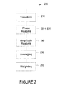
- FIG. 2 is a spatial analysis process.
- FIG. 3 is a second system that enhances spatialization.
- FIG. 4 is an antialiasing process.
- FIG. 5 is a block diagram of the spatialization system or spatialization process within a vehicle.
- FIG. 6 is a block diagram of the spatialization system or spatialization process within a wireless device or as part of a wireless architecture.
- a system enhances spatialization among a plurality of directional or omnidirectional input devices that may operate in tandem to convert sound into analog signals or digital data.
- the hardware and software convert and transmit voiced and unvoiced input across a wireless (e.g., radio, microwave, etc.) or physical medium to a system that enables a Signal-to-Noise Ratio (SNR) and spatial scalability.
- SNR Signal-to-Noise Ratio
- the spatial information about the relative location of the sound sources may be identified, mixed, and routed into one, two, or more audio or multimedia channels.
- a transmitter may electrically encode the digital channel data or analog channel signals that may be transmitted through the wireless or fixed medium to a multi-dimensional output system.
- the output system may decode the transmitted signals through a receiver to derive a two or more dimensional separation between the directional or omnidirectional inputs to reproduce the relative locations of the originating sound sources.
- the outputs may emulate an original directionality about the relative locations or, alternatively, may be scaled to exploit the separation between those signals.
- FIG. 1 is a schematic of a system 100 that enhances spatialization.
- the system 100 may be positioned at an originating location 150 in a communication arrangement such as, for example, a teleconferencing or video conferencing room, an interior of a vehicle (e.g., FIG. 3 ), or any other area or enclosure in which there are one or more speakers 152 (or other sound sources).
- the system 100 may comprise two or more standalone input devices or an array of devices or sensors that convert sound into continuous or discrete data such as a microphone array 102 that may couple a receiver 112 , spatial analyzer 104 and an audio mixer 106 .
- the microphone array 102 may, for example, comprise a pair of closely spaced omni-directional microphones.
- the spatial analyzer 104 may receive signals from each of the microphones in the microphone array 102 directly or indirectly through a decoder or converter that converts the received signals back to their original form.
- the microphone signals (e.g., that may be processed through one, two, or more channels) are analyzed to derive spatial information representing the locations of each speaker 152 relative to the microphone array 102 .
- the signals may then be combined, routed, and further processed to change the level, timbre, and/or dynamics of the signals.
- An electronic device, such as a transmitter 110 may encode the signals that may then be conveyed or radiated through a transmission media to another location.
- the transmitter 110 conveys signals through frequency modulation, amplitude modulation, or any wireless communication protocol such as cellular (e.g., Code Division Multiple Access (CDMA), Global System for Mobile Communication (GSM), etc.), Bluetooth, WLAN, WiFi, Hyper/LAN, Ultraband, WiMax, Mobile-Fi, or ZigBee mobility.
- cellular e.g., Code Division Multiple Access (CDMA), Global System for Mobile Communication (GSM), etc.
- Bluetooth Wireless Local Area Network
- WLAN Wireless Local Area Network
- WiFi Wireless Fidelity
- WLAN Wireless Local Area Network
- WiFi Wireless Fidelity
- WLAN Wireless Local Area Network
- the spatial information that characterizes the input signals may be derived through the spatial analyzer 104 that may execute or may be configured to render the functions of a spatial analysis process such as the spatial analysis process 200 shown in FIG. 2 .
- the analysis of the microphone signals may include hardware and/or software that transform each or selected temporal signals into the frequency domain at act 210 , compute a phase for each signal over a range of frequencies at 220 , and calculate a phase difference between the signals at 230 .
- the phase difference between the pair of signals may be converted into an angle (e.g., sine and cosine values) that may be processed to rotate the first signal into phase with a second signal and vice versa.
- An amplitude ratio may be computed from the rotated first signal and the second signal at 240 that may be averaged over a range of frequencies at 250 by execution of the software or an averaging circuit.
- An averaged amplitude ratio may be computed from the first signal and the rotated second signal at 250 .
- the averaged amplitude ratios may be converted into multipliers.
- the results of the analysis may derive sets of fading weights at 260 .
- Each set of fading weights may include weights for mixing corresponding microphone signals into each channel of a multichannel output signal 120 .
- the mixer 106 mixes the microphone signals in accordance with the sets of fading weights to generate the multichannel output signal 120 .
- the mixer 106 may further process the microphone signals to change the level of timber and/or dynamics of the audio signal.
- an extrapolator 310 may infer or estimate the weighting to be applied outside of an analysis region in an alternative system 300 .
- the extrapolator 310 may emulate an antialiasing filter or may execute software that renders the output similar to an outcome of an antialiasing process such as the antialiasing process 400 shown in FIG. 4 .
- the antialiasing process 400 may calculate or receive the average mixing weight factors for each channel within the analysis region at 410 .
- the weighting factors are then applied to the frequencies outside the analysis region using a (SNR) based application at 420 .
- the SNR value used to calculate a scale factor is multiplied by the mixing weight to arrive at the adjusted mixing weight for that frequency bin.
- Some antialiasing processes may roll-off and/or blend one or more channels to a noise level or below a noise level.
- the attenuation and/or blending may occur below a predetermined low frequency or first threshold and/or above a predetermined high frequency or second threshold.
- the high and low frequency thresholds may be empirically measured or quantitatively derived based on the desired frequency range of the system, the operating characteristics of the microphone array 102 , and/or the acoustic characteristics of the receiving location 160 .
- the analysis region is established by upper and lower limits.
- the lower limit may be established by the operating performance of the microphones that comprise the microphone array 102 .
- the upper limit may be established by the distance between the microphones (that comprise the microphone array 102 ) and the wavelength of the desired sound.
- the upper frequency limit of the analysis region may be determined by the ability of the microphone array 102 to discriminate individual frequencies based on the sequential microphone spacing. For example, if the individual microphones are separated by about 4 cm, the highest frequency some systems may analyze without aliasing may occur at around 4200 Hz.
- the lower frequency limit in this exemplary system, may be limited by the inherent uncertainty in the phase of the microphones.
- the analysis region is spatially constrained between about 1 k Hz to 4.2 k Hz.
- the system 100 may process the voices of far-field, relative to the microphone array 102 , speakers 152 (or other sound sources).
- the analysis of the microphone signals may be directed to or limited to the high frequency components of the signals.
- the analysis may derive a phase vector associated with each speaker 152 .
- the phase vector may be processed to derive the set of fading weights for each signal (or selected signals).
- the set of fading weights may be applied to some or the entire frequency range of each signal.
- the analysis of the microphone signals may include a time averaging or integrating component to mitigate short-term fluctuations in the sets of mixing weights.
- the analysis of the microphone signals may be a continuous or an asynchronous process that adapts and stores the set of mixing weights in memory over time in response to, for example, a speaker 152 moving around or changing positions in the originating location 150 , or upon an occurrence of an event, such as a pause in a detected speech.
- the output signal 120 may be transmitted through a wireless or tangible medium to a local or remote receiving location 160 where an audio or multimedia playback system 170 converts them into perceptible forms.
- the audio playback system 170 may convert the output signal 120 into aural signals near one or more listeners 162 through two or more output devices such as loudspeakers 175 .
- the listeners 162 may perceive the spatial information, derived from the relative positions of the speakers, in the output of the loudspeakers 175 .
- the voices of each speaker 152 may be perceived to come from a direction (e.g., through two, three, or more dimensions or coordinate directions such as a left, a right, etc., direction) in the receiving location 160 that is related to their relative positions in the originating location 150 .
- the listeners 162 may experience a higher quality fidelity (e.g., an enhanced spatialization) in which they are able to associate or perceive a relative spatial location with each of the speakers' 152 voices, which may enhance intelligibility.
- the system 100 may be used at a common or local location (e.g., the originating location 150 ) of a communication arrangement with two or more locations, or alternatively may be distributed across some or all remote participating locations in a communication arrangement or a communication network.
- each terminating location e.g., each receiving location 160
- the system 100 may include, for example, a two or more channel (e.g., stereo) configuration in which an input interface from an audio processing device, such as an audio mixer 106 may receive and decode two (e.g., a left and a right channel) or more channels.
- the audio playback system 170 processes the stereo output signal and transmits the content through the two or more loudspeakers 175 to render a more natural sound distribution.
- the methods or functionalities that enable the systems 100 and 300 may be implemented in software retained in a computer readable medium that may be executed by a processor (e.g., system or front end processors: 114 , 320 , and/or 330 ; receiving location processor 340 ).
- the systems, methods, and descriptions described may be programmed in one or more controllers, devices, processors (e.g., signal processors).
- the processors may comprise one or more central processing units that supervise the sequence of micro-operations that execute the instruction code and data coming from memory (e.g., computer readable medium) that generate, support, and/or complete an operation, compression, or signal modifications.
- the system or front end processors 114 , 320 , and 330 or front end processors 114 and 330 may comprise a single processor that interfaces with, is an integrated part, or a unitary part of the spatial analyzer 104 .
- the dedicated applications may support and define the functions of the special purpose processor or general purpose processor that is customized by instruction code (and in some applications may be resident to vehicles (e.g., FIG. 5 ), communication systems, audio systems, telephones, teleconferencing systems, fixed or mobile wireless devices, interface an in-vehicle bus, interface a universal serial bus (or buses having a bandwidth of about 1.5 megabits per second or greater), or interface cables such as audio or multimedia cables.
- a front-end processor may perform the complementary tasks of gathering data for a processor or program to work with, and for making the data and results available to other processors, controllers, or devices.
- the systems, methods, and descriptions may program one or more signal processors (e.g., system or front end processors: 114 , 320 , and/or 330 ; receiving location processor 340 ) or may be encoded in a signal bearing storage medium, a computer-readable medium, or may comprise logic stored in a memory that may be accessible through an interface and is executable by one or more processors.
- Some signal-bearing storage medium or computer-readable medium comprise a memory that is unitary or separate (e.g., local or remote) from a device, programmed within a device, such as one or more integrated circuits, or retained in memory and/or processed by a controller or a computer.
- the software or logic may reside in an electronic or optical memory resident to or interfaced to one or more processors, devices, or controllers that may support a tangible or visual communication interface (e.g., to a display), wireless communication interface, or a wireless system.
- the memory may retain an ordered listing of executable instructions in a processor, device, or controller accessible medium for implementing logical functions.
- a logical function may be implemented through digital circuitry, through source code, or through analog circuitry.
- the software may be embodied in any computer-readable medium, signal-bearing medium, or other non-transitory medium for use by, or in connection with, an instruction executable system, apparatus, and device, resident to system that may maintain persistent or non-persistent connections.
- Such a system may include a computer system, a processor-based system, or another system that includes an input and output interface that may communicate with a publicly accessible or privately accessible distributed network through a wireless or tangible communication bus through a public and/or proprietary protocol.
- a “computer-readable storage medium,” “machine-readable medium,” “propagated-signal” medium, and/or “signal-bearing medium” may comprise a medium (e.g., a non-transitory medium) that stores, communicates, propagates, or transports software or data for use by or in connection with an instruction executable system, apparatus, or device.
- the machine-readable medium may selectively be, but not limited to, an electronic, magnetic, optical, electromagnetic, infrared, or semiconductor system, apparatus, device, or propagation medium.
- a non-exhaustive list of examples of a machine-readable medium would include: an electrical connection having one or more wires, a portable magnetic or optical disk, a volatile memory, such as a Random Access Memory (RAM), a Read-Only Memory (ROM), an Erasable Programmable Read-Only Memory (EPROM or Flash memory), or an optical fiber.
- a machine-readable medium may also include a tangible medium, as the software may be electronically stored as an image or in another format (e.g., through an optical scan), then compiled, and/or interpreted or otherwise processed. The processed medium may then be stored in a computer and/or machine memory.
Abstract
Description
Claims (29)
Priority Applications (2)
| Application Number | Priority Date | Filing Date | Title |
|---|---|---|---|
| US13/020,954 US9036843B2 (en) | 2010-02-05 | 2011-02-04 | Enhanced spatialization system |
| US14/689,558 US9736611B2 (en) | 2010-02-05 | 2015-04-17 | Enhanced spatialization system |
Applications Claiming Priority (3)
| Application Number | Priority Date | Filing Date | Title |
|---|---|---|---|
| US30176110P | 2010-02-05 | 2010-02-05 | |
| US30174510P | 2010-02-05 | 2010-02-05 | |
| US13/020,954 US9036843B2 (en) | 2010-02-05 | 2011-02-04 | Enhanced spatialization system |
Related Child Applications (1)
| Application Number | Title | Priority Date | Filing Date |
|---|---|---|---|
| US14/689,558 Continuation US9736611B2 (en) | 2010-02-05 | 2015-04-17 | Enhanced spatialization system |
Publications (2)
| Publication Number | Publication Date |
|---|---|
| US20110194700A1 US20110194700A1 (en) | 2011-08-11 |
| US9036843B2 true US9036843B2 (en) | 2015-05-19 |
Family
ID=43929422
Family Applications (4)
| Application Number | Title | Priority Date | Filing Date |
|---|---|---|---|
| US13/020,954 Active 2032-10-30 US9036843B2 (en) | 2010-02-05 | 2011-02-04 | Enhanced spatialization system |
| US13/020,949 Active 2032-11-24 US8913757B2 (en) | 2010-02-05 | 2011-02-04 | Enhanced spatialization system with satellite device |
| US14/571,896 Active 2031-05-06 US9843880B2 (en) | 2010-02-05 | 2014-12-16 | Enhanced spatialization system with satellite device |
| US14/689,558 Active 2031-04-22 US9736611B2 (en) | 2010-02-05 | 2015-04-17 | Enhanced spatialization system |
Family Applications After (3)
| Application Number | Title | Priority Date | Filing Date |
|---|---|---|---|
| US13/020,949 Active 2032-11-24 US8913757B2 (en) | 2010-02-05 | 2011-02-04 | Enhanced spatialization system with satellite device |
| US14/571,896 Active 2031-05-06 US9843880B2 (en) | 2010-02-05 | 2014-12-16 | Enhanced spatialization system with satellite device |
| US14/689,558 Active 2031-04-22 US9736611B2 (en) | 2010-02-05 | 2015-04-17 | Enhanced spatialization system |
Country Status (3)
| Country | Link |
|---|---|
| US (4) | US9036843B2 (en) |
| EP (2) | EP2355558B1 (en) |
| CA (2) | CA2731043C (en) |
Cited By (1)
| Publication number | Priority date | Publication date | Assignee | Title |
|---|---|---|---|---|
| US20210110835A1 (en) * | 2016-03-10 | 2021-04-15 | Orange | Optimized coding and decoding of spatialization information for the parametric coding and decoding of a multichannel audio signal |
Families Citing this family (17)
| Publication number | Priority date | Publication date | Assignee | Title |
|---|---|---|---|---|
| US20130108053A1 (en) * | 2011-10-31 | 2013-05-02 | Otto A. Gygax | Generating a stereo audio data packet |
| US9374724B2 (en) * | 2011-11-03 | 2016-06-21 | Telefonaktiebolaget Lm Ericsson (Publ) | Channel estimation using reference signals |
| US9591405B2 (en) * | 2012-11-09 | 2017-03-07 | Harman International Industries, Incorporated | Automatic audio enhancement system |
| FR2998438A1 (en) * | 2012-11-16 | 2014-05-23 | France Telecom | ACQUISITION OF SPATIALIZED SOUND DATA |
| WO2016167138A1 (en) * | 2015-04-13 | 2016-10-20 | ソニー株式会社 | Signal processing device and method, and program |
| US10674255B2 (en) | 2015-09-03 | 2020-06-02 | Sony Corporation | Sound processing device, method and program |
| WO2017098949A1 (en) | 2015-12-10 | 2017-06-15 | ソニー株式会社 | Speech processing device, method, and program |
| US9875747B1 (en) * | 2016-07-15 | 2018-01-23 | Google Llc | Device specific multi-channel data compression |
| GB2561596A (en) * | 2017-04-20 | 2018-10-24 | Nokia Technologies Oy | Audio signal generation for spatial audio mixing |
| GB2566978A (en) * | 2017-09-29 | 2019-04-03 | Nokia Technologies Oy | Processing audio signals |
| US10644796B2 (en) * | 2018-04-20 | 2020-05-05 | Wave Sciences, LLC | Visual light audio transmission system and processing method |
| US11038589B2 (en) * | 2018-04-20 | 2021-06-15 | Wave Sciences, LLC | Visual light audio transmission system and processing method |
| US10631085B2 (en) * | 2018-05-07 | 2020-04-21 | Crestron Electronics, Inc. | Microphone array system with Ethernet connection |
| US10728662B2 (en) * | 2018-11-29 | 2020-07-28 | Nokia Technologies Oy | Audio mixing for distributed audio sensors |
| US10735887B1 (en) * | 2019-09-19 | 2020-08-04 | Wave Sciences, LLC | Spatial audio array processing system and method |
| GB2593448A (en) * | 2020-03-12 | 2021-09-29 | Nomono As | Wireless microphone system |
| CN112240941B (en) * | 2020-10-14 | 2022-07-29 | 中国人民解放军61540部队 | Relative calibration method and system for gravity satellite-borne accelerometer |
Citations (12)
| Publication number | Priority date | Publication date | Assignee | Title |
|---|---|---|---|---|
| US5793875A (en) | 1996-04-22 | 1998-08-11 | Cardinal Sound Labs, Inc. | Directional hearing system |
| EP1206161A1 (en) | 2000-11-10 | 2002-05-15 | Sony International (Europe) GmbH | Microphone array with self-adjusting directivity for handsets and hands free kits |
| US20030051532A1 (en) * | 2001-08-22 | 2003-03-20 | Mitel Knowledge Corporation | Robust talker localization in reverberant environment |
| US20040032487A1 (en) | 2002-04-15 | 2004-02-19 | Polycom, Inc. | Videoconferencing system with horizontal and vertical microphone arrays |
| US20040076301A1 (en) | 2002-10-18 | 2004-04-22 | The Regents Of The University Of California | Dynamic binaural sound capture and reproduction |
| WO2006006935A1 (en) | 2004-07-08 | 2006-01-19 | Agency For Science, Technology And Research | Capturing sound from a target region |
| US20060239471A1 (en) * | 2003-08-27 | 2006-10-26 | Sony Computer Entertainment Inc. | Methods and apparatus for targeted sound detection and characterization |
| US20080165993A1 (en) | 2007-01-05 | 2008-07-10 | Samsung Electronics Co., Ltd. | Directional speaker system and automatic set-up method thereof |
| US20080298610A1 (en) | 2007-05-30 | 2008-12-04 | Nokia Corporation | Parameter Space Re-Panning for Spatial Audio |
| US20090060222A1 (en) * | 2007-09-05 | 2009-03-05 | Samsung Electronics Co., Ltd. | Sound zoom method, medium, and apparatus |
| WO2009109217A1 (en) | 2008-03-03 | 2009-09-11 | Nokia Corporation | Apparatus for capturing and rendering a plurality of audio channels |
| US20090252356A1 (en) * | 2006-05-17 | 2009-10-08 | Creative Technology Ltd | Spatial audio analysis and synthesis for binaural reproduction and format conversion |
Family Cites Families (18)
| Publication number | Priority date | Publication date | Assignee | Title |
|---|---|---|---|---|
| KR100428709B1 (en) | 2001-08-17 | 2004-04-27 | 한국전자통신연구원 | Apparatus for Forward Beamforming using Feedback of Multipath Information and Method Thereof |
| US20060245601A1 (en) * | 2005-04-27 | 2006-11-02 | Francois Michaud | Robust localization and tracking of simultaneously moving sound sources using beamforming and particle filtering |
| AU2006291689B2 (en) | 2005-09-14 | 2010-11-25 | Lg Electronics Inc. | Method and apparatus for decoding an audio signal |
| WO2007058130A1 (en) | 2005-11-15 | 2007-05-24 | Yamaha Corporation | Teleconference device and sound emission/collection device |
| US8027485B2 (en) | 2005-11-21 | 2011-09-27 | Broadcom Corporation | Multiple channel audio system supporting data channel replacement |
| US7565288B2 (en) * | 2005-12-22 | 2009-07-21 | Microsoft Corporation | Spatial noise suppression for a microphone array |
| US8379868B2 (en) | 2006-05-17 | 2013-02-19 | Creative Technology Ltd | Spatial audio coding based on universal spatial cues |
| US9014377B2 (en) | 2006-05-17 | 2015-04-21 | Creative Technology Ltd | Multichannel surround format conversion and generalized upmix |
| US7626889B2 (en) * | 2007-04-06 | 2009-12-01 | Microsoft Corporation | Sensor array post-filter for tracking spatial distributions of signals and noise |
| US7940972B2 (en) * | 2007-05-16 | 2011-05-10 | General Electric Company | System and method of extended field of view image acquisition of an imaged subject |
| KR101238362B1 (en) * | 2007-12-03 | 2013-02-28 | 삼성전자주식회사 | Method and apparatus for filtering the sound source signal based on sound source distance |
| DE112008003305B4 (en) | 2008-01-31 | 2015-02-19 | Mitsubishi Electric Corp. | Band-splitting time compensation signal processing device |
| US8553901B2 (en) * | 2008-02-11 | 2013-10-08 | Cochlear Limited | Cancellation of bone-conducted sound in a hearing prosthesis |
| US9113240B2 (en) * | 2008-03-18 | 2015-08-18 | Qualcomm Incorporated | Speech enhancement using multiple microphones on multiple devices |
| US8189807B2 (en) * | 2008-06-27 | 2012-05-29 | Microsoft Corporation | Satellite microphone array for video conferencing |
| US8314829B2 (en) * | 2008-08-12 | 2012-11-20 | Microsoft Corporation | Satellite microphones for improved speaker detection and zoom |
| KR101519104B1 (en) * | 2008-10-30 | 2015-05-11 | 삼성전자 주식회사 | Apparatus and method for detecting target sound |
| WO2010124274A1 (en) * | 2009-04-24 | 2010-10-28 | Wayne State University | 3d soundscaping |
-
2011
- 2011-02-04 US US13/020,954 patent/US9036843B2/en active Active
- 2011-02-04 CA CA2731043A patent/CA2731043C/en active Active
- 2011-02-04 EP EP11153430.1A patent/EP2355558B1/en active Active
- 2011-02-04 US US13/020,949 patent/US8913757B2/en active Active
- 2011-02-04 EP EP11153433.5A patent/EP2355559B1/en active Active
- 2011-02-04 CA CA2731045A patent/CA2731045C/en active Active
-
2014
- 2014-12-16 US US14/571,896 patent/US9843880B2/en active Active
-
2015
- 2015-04-17 US US14/689,558 patent/US9736611B2/en active Active
Patent Citations (13)
| Publication number | Priority date | Publication date | Assignee | Title |
|---|---|---|---|---|
| US5793875A (en) | 1996-04-22 | 1998-08-11 | Cardinal Sound Labs, Inc. | Directional hearing system |
| EP1206161A1 (en) | 2000-11-10 | 2002-05-15 | Sony International (Europe) GmbH | Microphone array with self-adjusting directivity for handsets and hands free kits |
| US20030051532A1 (en) * | 2001-08-22 | 2003-03-20 | Mitel Knowledge Corporation | Robust talker localization in reverberant environment |
| US20040032487A1 (en) | 2002-04-15 | 2004-02-19 | Polycom, Inc. | Videoconferencing system with horizontal and vertical microphone arrays |
| US20040076301A1 (en) | 2002-10-18 | 2004-04-22 | The Regents Of The University Of California | Dynamic binaural sound capture and reproduction |
| US20060239471A1 (en) * | 2003-08-27 | 2006-10-26 | Sony Computer Entertainment Inc. | Methods and apparatus for targeted sound detection and characterization |
| WO2006006935A1 (en) | 2004-07-08 | 2006-01-19 | Agency For Science, Technology And Research | Capturing sound from a target region |
| US20090252356A1 (en) * | 2006-05-17 | 2009-10-08 | Creative Technology Ltd | Spatial audio analysis and synthesis for binaural reproduction and format conversion |
| US20080165993A1 (en) | 2007-01-05 | 2008-07-10 | Samsung Electronics Co., Ltd. | Directional speaker system and automatic set-up method thereof |
| US20080298610A1 (en) | 2007-05-30 | 2008-12-04 | Nokia Corporation | Parameter Space Re-Panning for Spatial Audio |
| US20090060222A1 (en) * | 2007-09-05 | 2009-03-05 | Samsung Electronics Co., Ltd. | Sound zoom method, medium, and apparatus |
| WO2009109217A1 (en) | 2008-03-03 | 2009-09-11 | Nokia Corporation | Apparatus for capturing and rendering a plurality of audio channels |
| US20110002469A1 (en) * | 2008-03-03 | 2011-01-06 | Nokia Corporation | Apparatus for Capturing and Rendering a Plurality of Audio Channels |
Non-Patent Citations (3)
| Title |
|---|
| Communication from the European Patent Office re Intent to Grant for corresponding European Application No. 11 153 430.1, dated Jun. 13, 2013 (11 pages). |
| European Search Report dated Mar. 19, 2012, for corresponding European Application No. 11 153 430.1-2225, 7 pages. |
| Irvine, Interaural Intensity Difference, 2001, Fig.1. * |
Cited By (2)
| Publication number | Priority date | Publication date | Assignee | Title |
|---|---|---|---|---|
| US20210110835A1 (en) * | 2016-03-10 | 2021-04-15 | Orange | Optimized coding and decoding of spatialization information for the parametric coding and decoding of a multichannel audio signal |
| US11664034B2 (en) * | 2016-03-10 | 2023-05-30 | Orange | Optimized coding and decoding of spatialization information for the parametric coding and decoding of a multichannel audio signal |
Also Published As
| Publication number | Publication date |
|---|---|
| CA2731045C (en) | 2015-12-29 |
| EP2355558B1 (en) | 2013-11-13 |
| CA2731043A1 (en) | 2011-08-05 |
| US9843880B2 (en) | 2017-12-12 |
| US20150223003A1 (en) | 2015-08-06 |
| EP2355559A1 (en) | 2011-08-10 |
| EP2355559B1 (en) | 2013-06-19 |
| US20110194704A1 (en) | 2011-08-11 |
| US20110194700A1 (en) | 2011-08-11 |
| US9736611B2 (en) | 2017-08-15 |
| US20150098573A1 (en) | 2015-04-09 |
| CA2731043C (en) | 2015-12-29 |
| US8913757B2 (en) | 2014-12-16 |
| CA2731045A1 (en) | 2011-08-05 |
| EP2355558A1 (en) | 2011-08-10 |
Similar Documents
| Publication | Publication Date | Title |
|---|---|---|
| US9736611B2 (en) | Enhanced spatialization system | |
| CN106170992B (en) | Object-based audio loudness management | |
| CN106716526B (en) | Method and apparatus for enhancing sound sources | |
| US11950063B2 (en) | Apparatus, method and computer program for audio signal processing | |
| CN112219411B (en) | Spatial sound rendering | |
| EP3416410B1 (en) | Audio processing device, audio processing method, and computer program product | |
| CN111630592A (en) | Apparatus, method and computer program for encoding, decoding, scene processing and other processes related to DirAC-based spatial audio coding | |
| CA2917376C (en) | Audio processor for orientation-dependent processing | |
| CN112567765A (en) | Spatial audio capture, transmission and reproduction | |
| GB2576769A (en) | Spatial parameter signalling | |
| EP2941770A1 (en) | Method for determining a stereo signal | |
| WO2013022483A1 (en) | Methods and apparatus for automatic audio adjustment | |
| EP3860151A1 (en) | Audio / video capturing using audio from remote device | |
| WO2023156176A1 (en) | Parametric spatial audio rendering | |
| CN117581299A (en) | Creating a spatial audio stream from audio objects having a spatial range | |
| CN115938388A (en) | Three-dimensional audio signal processing method and device |
Legal Events
| Date | Code | Title | Description |
|---|---|---|---|
| AS | Assignment |
Owner name: QNX SOFTWARE SYSTEMS CO., CANADA Free format text: ASSIGNMENT OF ASSIGNORS INTEREST;ASSIGNORS:HETHERINGTON, PHILLIP A.;FALLAT, MARK;SIGNING DATES FROM 20110517 TO 20110518;REEL/FRAME:026410/0529 |
|
| AS | Assignment |
Owner name: QNX SOFTWARE SYSTEMS LIMITED, CANADA Free format text: CHANGE OF NAME;ASSIGNOR:QNX SOFTWARE SYSTEMS CO.;REEL/FRAME:027768/0863 Effective date: 20120217 |
|
| AS | Assignment |
Owner name: 2236008 ONTARIO INC., ONTARIO Free format text: ASSIGNMENT OF ASSIGNORS INTEREST;ASSIGNOR:8758271 CANADA INC.;REEL/FRAME:032607/0674 Effective date: 20140403 Owner name: 8758271 CANADA INC., ONTARIO Free format text: ASSIGNMENT OF ASSIGNORS INTEREST;ASSIGNOR:QNX SOFTWARE SYSTEMS LIMITED;REEL/FRAME:032607/0943 Effective date: 20140403 |
|
| STCF | Information on status: patent grant |
Free format text: PATENTED CASE |
|
| MAFP | Maintenance fee payment |
Free format text: PAYMENT OF MAINTENANCE FEE, 4TH YEAR, LARGE ENTITY (ORIGINAL EVENT CODE: M1551); ENTITY STATUS OF PATENT OWNER: LARGE ENTITY Year of fee payment: 4 |
|
| AS | Assignment |
Owner name: BLACKBERRY LIMITED, ONTARIO Free format text: ASSIGNMENT OF ASSIGNORS INTEREST;ASSIGNOR:2236008 ONTARIO INC.;REEL/FRAME:053313/0315 Effective date: 20200221 |
|
| MAFP | Maintenance fee payment |
Free format text: PAYMENT OF MAINTENANCE FEE, 8TH YEAR, LARGE ENTITY (ORIGINAL EVENT CODE: M1552); ENTITY STATUS OF PATENT OWNER: LARGE ENTITY Year of fee payment: 8 |