US9005270B2 - High metal to vessel ratio stent and method - Google Patents

High metal to vessel ratio stent and method Download PDF

Info

Publication number
US9005270B2
US9005270B2 US13/430,942 US201213430942A US9005270B2 US 9005270 B2 US9005270 B2 US 9005270B2 US 201213430942 A US201213430942 A US 201213430942A US 9005270 B2 US9005270 B2 US 9005270B2
Authority
US
United States
Prior art keywords
prosthesis
high metal
vessel ratio
vessel
ratio stent
Prior art date
Legal status (The legal status is an assumption and is not a legal conclusion. Google has not performed a legal analysis and makes no representation as to the accuracy of the status listed.)
Active, expires
Application number
US13/430,942
Other versions
US20130261728A1 (en
Inventor
Keith Perkins
Samuel Robaina
Jeffery Argentine
Walter Bruszewski
Andrew Kiehl
Current Assignee (The listed assignees may be inaccurate. Google has not performed a legal analysis and makes no representation or warranty as to the accuracy of the list.)
Medtronic Vascular Inc
Original Assignee
Medtronic Vascular Inc
Priority date (The priority date is an assumption and is not a legal conclusion. Google has not performed a legal analysis and makes no representation as to the accuracy of the date listed.)
Filing date
Publication date
Application filed by Medtronic Vascular Inc filed Critical Medtronic Vascular Inc
Priority to US13/431,732 priority Critical patent/US8911490B2/en
Priority to US13/430,942 priority patent/US9005270B2/en
Assigned to MEDTRONIC VASCULAR, INC. reassignment MEDTRONIC VASCULAR, INC. ASSIGNMENT OF ASSIGNORS INTEREST (SEE DOCUMENT FOR DETAILS). Assignors: KIEHL, ANDREW, BURSZEWSKI, WALTER, ARGENTINE, JEFFERY, PERKINS, KEITH, ROBAINA, SAMUEL
Priority to EP13708292.1A priority patent/EP2830547B1/en
Priority to PCT/US2013/026547 priority patent/WO2013148012A1/en
Publication of US20130261728A1 publication Critical patent/US20130261728A1/en
Application granted granted Critical
Publication of US9005270B2 publication Critical patent/US9005270B2/en
Active legal-status Critical Current
Adjusted expiration legal-status Critical

Links

Images

Classifications

    • AHUMAN NECESSITIES
    • A61MEDICAL OR VETERINARY SCIENCE; HYGIENE
    • A61FFILTERS IMPLANTABLE INTO BLOOD VESSELS; PROSTHESES; DEVICES PROVIDING PATENCY TO, OR PREVENTING COLLAPSING OF, TUBULAR STRUCTURES OF THE BODY, e.g. STENTS; ORTHOPAEDIC, NURSING OR CONTRACEPTIVE DEVICES; FOMENTATION; TREATMENT OR PROTECTION OF EYES OR EARS; BANDAGES, DRESSINGS OR ABSORBENT PADS; FIRST-AID KITS
    • A61F2/00Filters implantable into blood vessels; Prostheses, i.e. artificial substitutes or replacements for parts of the body; Appliances for connecting them with the body; Devices providing patency to, or preventing collapsing of, tubular structures of the body, e.g. stents
    • A61F2/82Devices providing patency to, or preventing collapsing of, tubular structures of the body, e.g. stents
    • A61F2/86Stents in a form characterised by the wire-like elements; Stents in the form characterised by a net-like or mesh-like structure
    • A61F2/90Stents in a form characterised by the wire-like elements; Stents in the form characterised by a net-like or mesh-like structure characterised by a net-like or mesh-like structure
    • A61F2/91Stents in a form characterised by the wire-like elements; Stents in the form characterised by a net-like or mesh-like structure characterised by a net-like or mesh-like structure made from perforated sheet material or tubes, e.g. perforated by laser cuts or etched holes
    • A61F2/915Stents in a form characterised by the wire-like elements; Stents in the form characterised by a net-like or mesh-like structure characterised by a net-like or mesh-like structure made from perforated sheet material or tubes, e.g. perforated by laser cuts or etched holes with bands having a meander structure, adjacent bands being connected to each other
    • A61F2002/91525Stents in a form characterised by the wire-like elements; Stents in the form characterised by a net-like or mesh-like structure characterised by a net-like or mesh-like structure made from perforated sheet material or tubes, e.g. perforated by laser cuts or etched holes with bands having a meander structure, adjacent bands being connected to each other within the whole structure different bands showing different meander characteristics, e.g. frequency or amplitude

Definitions

  • the present application relates to an intra-vascular device and method. More particularly, the present application relates to a device for treatment of intra-vascular diseases.
  • a conventional stent-graft typically includes a radially expandable reinforcement structure, formed from a plurality of annular stent rings, and a cylindrically shaped layer of graft material, sometimes called graft cloth, defining a lumen to which the stent rings are coupled.
  • Main stent-grafts are well known for use in tubular shaped human vessels.
  • endovascular aneurysmal exclusion is a method of using a stent-graft to exclude pressurized fluid flow from the interior of an aneurysm, thereby reducing the risk of rupture of the aneurysm and the associated invasive surgical intervention.
  • Stent-grafts with custom side openings are sometimes fabricated to accommodate the particular vessel structure of each individual patient. Specifically, as the location of branch vessels emanating from a main vessel, e.g., having the aneurysm, varies from patient to patient, stent-grafts are fabricated with side openings customized to match the position of the branch vessels of the particular patient. However, custom fabrication of stent-grafts is relatively expensive and time consuming.
  • the stent-grafts must be deployed such that the custom side openings are precisely aligned with the respective locations of the branch vessels. This is a relatively complex procedure thus increasing the risk of the procedure.
  • a method includes covering ostai of branch vessels emanating from a main vessel and an aneurysm with a high metal to vessel ratio stent.
  • a metal to vessel ratio of the high metal to vessel ratio stent is sufficiently high to encourage tissue ingrowth around the high metal to vessel ratio stent yet is sufficiently low to ensure perfusion of the branch vessels through the high metal to vessel ratio stent.
  • the ingrowth of tissue provides secure fixation and sealing of the high metal to vessel ratio stent to the main vessel (tissue remodeling) and essentially eliminates the aneurysm from the main vessel circulation.
  • the high metal to vessel ratio stent is deployed without having to rotationally position the high metal to vessel ratio stent to allow for the perfusion of the target branch vessels as is currently done with branched and fenestrated devices.
  • FIG. 1 is a perspective outline view of a high metal to vessel ratio stent in its final configuration in accordance with one embodiment
  • FIG. 2 is a cross-sectional view of the high metal to vessel ratio stent of FIG. 1 ;
  • FIG. 3 is an enlarged plan view of a region of the high metal to vessel ratio stent of FIG. 1 in its final configuration in accordance with one embodiment
  • FIG. 4 is an enlarged plan view of the region of the high metal to vessel ratio stent of FIG. 3 in its constrained configuration in accordance with one embodiment
  • FIG. 5 is an enlarged plan view of the region of the high metal to vessel ratio stent of FIG. 1 in its final configuration in accordance with another embodiment
  • FIG. 7 is an enlarged plan view of the region of the high metal to vessel ratio stent of FIG. 1 in its final configuration in accordance with yet another embodiment
  • FIG. 8 is an enlarged plan view of the region of the high metal to vessel ratio stent of FIG. 7 in its constrained configuration in accordance with one embodiment
  • FIG. 9 is an enlarged plan view of the region of the high metal to vessel ratio stent of FIG. 1 in its final configuration in accordance with yet another embodiment
  • FIG. 10 is a cross-section view of the high metal to vessel ratio stent along the line X-X of FIG. 9 in accordance with one embodiment
  • FIG. 11 is an enlarged plan view of the region of the high metal to vessel ratio stent of FIG. 1 in its final configuration in accordance with yet another embodiment
  • FIG. 12 is an enlarged plan view of the region of the high metal to vessel ratio stent of FIG. 1 in its final configuration in accordance with yet another embodiment
  • FIG. 13 is a perspective view of a high metal to vessel ratio stent in accordance with another embodiment
  • FIG. 14 is a cross-sectional view of a vessel assembly including a delivery system including the high metal to vessel ratio stent of FIGS. 1 and 2 in accordance with one embodiment;
  • FIG. 15 is a cross-sectional view of the vessel assembly including the delivery system at a later stage of deploying the high metal to vessel ratio stent of FIGS. 1 and 2 in accordance with one embodiment;
  • FIG. 16 is a cross-sectional view of the vessel assembly of FIGS. 14-15 after deployment of the high metal to vessel ratio stent of FIGS. 1 and 2 in accordance with one embodiment
  • FIG. 17 is a cross-sectional view of the vessel assembly of FIG. 16 illustrating tissue ingrowth into the high metal to vessel ratio stent.
  • a method includes covering ostai 1422 , 1424 of branch vessels 1408 , 1410 emanating from a main vessel 1404 with a high metal to vessel ratio stent 100 .
  • a metal to vessel ratio of high metal to vessel ratio stent 100 is sufficiently high to encourage tissue ingrowth around high metal to vessel ratio stent 100 yet is sufficiently low to ensure perfusion of branch vessels 1408 , 1410 through high metal to vessel ratio stent 100 .
  • the ingrowth of tissue provides secure fixation and sealing of high metal to vessel ratio stent 100 to main vessel 1404 thus minimizing the risk of endoleaks and migration.
  • high metal to vessel ratio stent 100 deployment of high metal to vessel ratio stent 100 is relatively simple thus minimizing the complexity and thus risk of deploying high metal to vessel ratio stent 100 . More particularly, as the entire high metal to vessel ratio stent 100 is permeable, high metal to vessel ratio stent 100 is deployed without having to rotationally position high metal to vessel ratio stent 100 to be aligned with branch vessels 1408 , 1410 as is currently done with deployment of branched and fenestrated devices.
  • the method further includes covering and excluding an aneurysm 1406 of main vessel 1404 with high metal to vessel ratio stent 100 .
  • aneurysm 1406 of main vessel 1404 with high metal to vessel ratio stent 100 .
  • the ingrowth of tissue 1702 restricts expansion of aneurysm 1406 .
  • aneurysm 1406 is remodeled and essentially eliminated as illustrated in FIG. 17 .
  • FIG. 1 is a perspective outline view of a high metal to vessel ratio stent 100 , e.g., an abdominal aortic stent, in its final configuration in accordance with one embodiment.
  • FIG. 2 is a cross-sectional view of high metal to vessel ratio stent 100 of FIG. 1 .
  • High metal to vessel ratio stent 100 is sometimes called an endoluminal flow disrupting device.
  • the proximal end of a prosthesis such as high metal to vessel ratio stent 100 is the end closest to the heart via the path of blood flow whereas the distal end is the end furthest away from the heart during deployment.
  • the distal end of the delivery system is usually identified to the end that is farthest from the operator (handle) while the proximal end of the delivery system is the end nearest the operator (handle).
  • the distal end of the delivery system is the end that is farthest from the operator (the end furthest from the handle) while the distal end of the prosthesis is the end nearest the operator (the end nearest the handle), i.e., the distal end of the delivery system and the proximal end of the prosthesis are the ends furthest from the handle while the proximal end of the delivery system and the distal end of the prosthesis are the ends nearest the handle.
  • the distal end of the delivery system and the proximal end of the prosthesis are the ends furthest from the handle while the proximal end of the delivery system and the distal end of the prosthesis are the ends nearest the handle.
  • High metal to vessel ratio stent 100 is cylindrical and includes a longitudinal axis L.
  • a main lumen 106 is defined by high metal to vessel ratio stent 100 and extends generally parallel to longitudinal axis L and between proximal main opening 102 and distal main opening 104 of high metal to vessel ratio stent 100 .
  • high metal to vessel ratio stent 100 has a substantially uniform diameter D.
  • high metal to vessel ratio stent 100 has a non-uniform diameter.
  • High metal to vessel ratio stent 100 is a semi-permeable barrier made of patterned material 108 , e.g., is a dense laser cut metal pattern.
  • High metal to vessel ratio stent 100 includes patterned material 108 and a plurality of holes 110 through which fluid, e.g., blood, can pass.
  • high metal to vessel ratio stent 100 is permeable, sometimes called porous, to fluid, i.e., fluid can pass through high metal to vessel ratio stent 100 and more particularly, through holes 110 .
  • high metal to vessel ratio stent 100 is permeable to tissue ingrowth.
  • Longitudinal direction 112 is the direction along high metal to vessel ratio stent 100 parallel to longitudinal axis L.
  • Circumferential direction 114 is the direction along the circumference of high metal to vessel ratio stent 100 in plane perpendicular to longitudinal axis L of high metal to vessel ratio stent 100 .
  • Radial direction 116 is along a radius extending from longitudinal axis L in plane perpendicular to longitudinal axis L of high metal to vessel ratio stent 100 .
  • holes 110 there are a plurality, e.g., three or more, of holes 110 arranged in both longitudinal direction 112 as well as circumferential direction 114 .
  • the ratio of material 108 per unit area of high metal to vessel ratio stent 100 is high, e.g., greater than or equal 30%. This ratio is sometimes called the metal to vessel ratio (or metal to artery ratio) as it defines the percent of the vessel covered with material 108 per unit area of the vessel. Stated another way, the percentage of high metal to vessel ratio stent 100 formed by material 108 is high, e.g., greater than or equal to 30%, and the percentage of high metal to vessel ratio stent 100 formed of holes 110 is low, e.g., less than or equal to 70%.
  • the metal to vessel ratio is defined as the area occupied by material 108 of high metal to vessel ratio stent 100 for a unit area of high metal to vessel ratio stent 100 when in the final configuration.
  • Y is the metal to vessel ratio expressed as percent.
  • the metal to vessel ratio can be expressed as a fraction, e.g., 0.4 for this example, or as a percentage, e.g., 40% for this example. To convert, the fraction is multiplied by 100 to obtain the percentage.
  • the metal to vessel ratio of high metal to vessel ratio stent 100 varies in the longitudinal direction 112 and/or in the circumferential direction 114 along high metal to vessel ratio stent 100 .
  • High metal to vessel ratio stent 100 is in a constrained configuration when high metal to vessel ratio stent 100 is constrained to a reduced diameter, e.g., within a delivery sheath. Further, high metal to vessel ratio stent 100 is in a constrained configuration when high metal to vessel ratio stent 100 is constrained to a reduced or expanded length, e.g., by longitudinally compressing or expanding high metal to vessel ratio stent 100 . When in the constrained configuration, either in length, diameter, or both, holes 110 are collapsed resulting in a much higher metal to vessel ratio for high metal to vessel ratio stent 100 than when high metal to vessel ratio stent 100 and is in its final configuration.
  • the metal to vessel ratio of high metal to vessel ratio stent 100 is sufficiently high to encourage tissue ingrowth around high metal to vessel ratio stent 100 .
  • the metal to vessel ratio of high metal to vessel ratio stent 100 is sufficiently low to ensure adequate perfusion of branch vessel(s) through high metal to vessel ratio stent 100 .
  • the metal to vessel ratio of high metal to vessel ratio stent 100 is within the range of 30 percent to 80 percent (30-80%), more suitably within the range of 35 percent to 60 percent (35-60%). In one particular embodiment, the metal to vessel ratio is 40 percent (40%).
  • high metal to vessel ratio stent 100 is formed of balloon expandable and/or self-expanding metal, e.g., e.g., formed of Nitinol or stainless steel.
  • high metal to vessel ratio stent 100 is a laser cut, etched, or wire formed stent.
  • a cylindrical tube of metal e.g., Nitinol
  • the cylindrical tube of metal can be formed from a metal sheet that is bent and welded in one embodiment.
  • high metal to vessel ratio stent 100 has a thickness T, e.g., equal to the thickness of the cylindrical tube from which high metal to vessel ratio stent 100 is formed. Thickness T is the distance between the inner cylindrical surface 118 and the outer cylindrical surface 120 of high metal to vessel ratio stent 100 .
  • Serpentine rings 302 includes a zigzag pattern, sometimes called a sinusoidal or an alternating repeating pattern. More particularly, each serpentine ring 302 includes a repeating pattern of proximal apexes 304 and distal apexes 306 connected by struts 308 . Proximal apexes 304 and distal apexes 306 are sometimes called peaks and valleys, respectively, or crowns.
  • Proximal apexes 304 define the proximal edge 310 of each serpentine ring 302 .
  • Proximal edge 310 is an imaginary circle at proximal apexes 304 in a plane perpendicular to longitudinal axis L of high metal to vessel ratio stent 100 .
  • distal apexes 306 define the distal edge 312 of each serpentine ring 302 .
  • Distal edge 312 is an imaginary circle at distal apexes 306 in a plane perpendicular to longitudinal axis L of high metal to vessel ratio stent 100 .
  • Struts 308 generally extend between proximal edge 310 and distal edge 312 of each serpentine ring 302 .
  • serpentine rings 302 include a first serpentine ring 302 A.
  • Serpentine ring 302 A includes a proximal edge 310 at proximal apexes 304 , a distal edge 312 at distal apexes 306 , and struts 308 extending between proximal edge 310 and distal edge 312 .
  • serpentine ring 302 A includes a first distal apex 306 A and a second distal apex 306 B of the plurality of distal apexes 306 of serpentine ring 302 A.
  • Serpentine ring 302 A includes a first proximal apex 304 A of the plurality of proximal apexes 304 of serpentine ring 302 A.
  • Serpentine ring 302 A further includes a first strut 308 A and a second strut 308 B of the plurality of struts 308 of serpentine ring 302 A.
  • Distal apex 306 A is connected to proximal apex 304 A by strut 308 A.
  • Proximal apex 304 A is connected to distal apex 306 B by strut 308 B.
  • Each proximal apex 304 has two respective struts 308 extending therefrom.
  • proximal apex 304 A has struts 308 A, 308 B extending therefrom, which are thus the two respective struts 308 of proximal apex 304 A.
  • Each proximal apex 304 includes an extrados surface 314 and an intrados surface 316 .
  • Extrados surface 314 is the exterior surface of the curve of each proximal apex 304 .
  • intrados surface 316 is the interior surface of the curve of a proximal apex 304 .
  • each strut 308 includes an exterior radial surface 318 and an interior radial surface 320 .
  • Exterior radial surfaces 318 are further outward, or exterior, to interior radial surfaces 320 in circumferential direct 114 with respect to the respective proximal apex 304 .
  • Exterior radial surfaces 318 and interior radial surfaces 320 are parallel to and extend in radial direction 116 from inner cylindrical surface 118 to outer cylindrical surface 120 of high metal to vessel ratio stent 100 .
  • exterior radial surfaces 318 are continuous with extrados surfaces 314 and interior radial surfaces 320 are continuous with intrados surfaces 316 .
  • strut 308 A includes an exterior radial surface 318 A and an interior radial surface 320 A.
  • strut 308 B includes an exterior radial surface 318 B and an interior radial surface 320 B.
  • Proximal apexes 304 of serpentine rings 302 are directly connected to distal apexes 306 of the adjacent proximal serpentine ring 302 .
  • serpentine rings 302 include a second serpentine ring 302 B.
  • Proximal apexes 304 of serpentine ring 302 B are connected to distal apexes 306 of serpentine ring 302 A.
  • serpentine ring 302 A is proximal to serpentine ring 302 B.
  • proximal apexes 304 of the most proximal of serpentine rings 302 are unconnected to another serpentine ring and define the proximal end 100 P of high metal to vessel ratio stent 100 .
  • distal apexes 306 of the most distal of serpentine rings 302 are unconnected to another serpentine ring and define the distal end 100 D of high metal to vessel ratio stent 100 .
  • each strut 308 includes a plurality of fingers 322 . Fingers 322 increase the surface area of material 108 as compared to the area of serpentine rings 302 alone.
  • Fingers 322 are protrusions that protrude from struts 308 in a direction along the imaginary cylinder of high metal to vessel ratio stent 100 . More particularly, each finger 322 includes a knuckle 324 directly attached to a strut 308 and a tip 326 . Each finger 322 extends from knuckle 324 and strut 308 to tip 326 , where the finger 322 ends.
  • a first finger 322 A of the plurality of fingers 322 is attached to strut 308 A.
  • Finger 322 A includes a knuckle 324 directly attached to strut 308 A and a tip 326 .
  • each strut 308 includes a plurality of fingers 322 on both the exterior radial surface 318 and the interior radial surface 320 .
  • strut 308 A includes fingers 322 on exterior radial surface 318 A and interior radial surface 320 A.
  • the pattern of fingers 322 on an interior radial surface 320 of a first strut 308 of the two respective struts 308 of the proximal apex 304 is the same, or approximately the same, as the pattern of fingers 322 on an exterior radial surface 318 of a second strut 308 of the two respective struts 308 of the proximal apex 304 .
  • the pattern of fingers 322 on interior radial surface 320 A (or 320 B) of a first strut 308 A (or 308 B) of the two respective struts 308 A, 308 B of proximal apex 304 A is the same as the pattern of fingers 322 on exterior radial surface 318 B (or 318 A) of a second strut 308 B of the two respective struts 308 A, 308 B of proximal apex 304 A, respectively.
  • the pattern of fingers 322 on an interior radial surface 320 of a first strut 308 of the two respective struts 308 of the proximal apex 304 is different than, and interdigitated with, the pattern of fingers 322 on an interior radial surface 320 of a second strut 308 of the two respective struts 308 of the proximal apex 304 .
  • the pattern of fingers 322 on interior radial surface 320 A of a first strut 308 A of the two respective struts 308 A, 308 B of proximal apex 304 A is different than, and interdigitated with, the pattern of fingers 322 on interior radial surface 320 B of a second strut 308 B of the two respective struts 308 A, 308 B of proximal apex 304 A, respectively.
  • fingers 322 on directly adjacent radial surfaces of directly adjacent struts 308 are interdigitated with one another.
  • fingers 322 on exterior radial surface 318 B of strut 308 B are interdigitated with fingers 322 on a directly adjacent exterior radial surface 318 C of the directly adjacent strut 308 C.
  • high metal to vessel ratio stent 100 includes a plurality of holes 110 .
  • each hole 110 is defined by a stent cell 328 of high metal to vessel ratio stent 100 .
  • stent cell 328 is defined by: (1) a proximal apex 304 of a first serpentine ring 302 ; (2) the respective struts 308 of element ( 1 ); (3) the respective distal apexes 306 connected to element ( 2 ); (4) the proximal apexes 304 of the next serpentine ring 302 that are connected to element ( 3 ); (5) the directly adjacent struts 308 that are connected to element ( 4 ); (6) the distal apex 306 connected to element ( 5 ), and the fingers 322 protruding into the respective hole 110 from elements ( 2 ), ( 5 ).
  • FIG. 4 is an enlarged plan view of the region 122 of high metal to vessel ratio stent 100 of FIG. 3 in its constrained configuration in accordance with one embodiment.
  • FIG. 4 corresponds to the view of FIG. 3 , however, in FIG. 4 , high metal to vessel ratio stent 100 is in the constrained, e.g., radially collapsed, configuration, whereas in FIG. 3 , high metal to vessel ratio stent 100 is in the final, e.g., radially expanded, configuration.
  • fingers 322 on directly adjacent radial surfaces of directly adjacent struts 308 fit one within another, i.e., are interdigitated. This allows high metal to vessel ratio stent 100 to be radially collapsed to an extremely small diameter.
  • FIG. 5 is an enlarged plan view of the region 122 of high metal to vessel ratio stent 100 of FIG. 1 in its final configuration in accordance with another embodiment. Region 122 as illustrated in FIG. 5 is similar to region 122 as illustrated in FIG. 3 and only the significant differences are discussed below.
  • high metal to vessel ratio stent 100 includes serpentine rings 302 including serpentine rings 302 A, 302 B, proximal apexes including proximal apex 304 A, distal apexes 306 including distal apexes 306 A, 306 B, struts 308 including struts 308 A, 308 B, 308 C, proximal edges 310 , distal edges 312 , extrados surfaces 314 , intrados surfaces 316 , exterior radial surfaces 318 including exterior radial surfaces 318 A, 318 B, 318 C, internal radial surfaces 320 including internal radial surfaces 320 A, 320 B as discussed above in relation to FIGS. 3 , 4 .
  • high metal to vessel ratio stent 100 includes projections 502 . More particularly, a projection 502 is attached to each proximal apex 304 and protrudes distally therefrom. Similarly, a projection 502 is attached to each distal apex 306 and protrudes proximal therefrom.
  • Stems 504 include serpentine ring attachment ends 508 and petal attachment ends 510 .
  • Serpentine ring attachment ends 508 are directly attached to a serpentine ring 302 , i.e., a proximal apex 304 or a distal apex 306 .
  • Petals 506 are directly attached to petal attachment ends 510 of stems 504 .
  • each projection 502 includes two petals 506 .
  • Petals 506 are located in circumferential direction 114 approximately between directly adjacent apexes of a serpentine ring 302 .
  • a first projection 502 A is attached to proximal apex 304 A of serpentine ring 302 A and protrudes distally therefrom.
  • a second projection 502 B is attached to a distal apex 306 of serpentine ring 302 B and protrudes proximal therefrom.
  • petals 506 of first projection 502 A are located in circumferential direction 114 between directly adjacent distal apexes 306 A, 306 B of serpentine ring 302 A.
  • petals 506 of second projection 502 B are located in circumferential direction 114 between directly adjacent proximal apexes 304 of serpentine ring 302 B.
  • each stem 504 includes a plurality of fingers 322 attached thereto. Fingers 322 , and the number thereof, are optional, and generally are provided to obtain a desired metal to vessel ratio of high metal to vessel ratio stent 100 .
  • high metal to vessel ratio stent 100 includes a plurality of holes 110 .
  • each hole 110 is defined by a stent cell 512 of high metal to vessel ratio stent 100 .
  • stent cell 512 is defined by: (1) a proximal apex 304 of a first serpentine ring 302 ; (2) the respective struts 308 of element ( 1 ); (3) the respective distal apexes 306 connected to element ( 2 ); (4) the proximal apexes 304 of the next serpentine ring 302 that are connected to element ( 3 ); (5) the directly adjacent struts 308 that are connected to element ( 4 ); (6) the distal apex 306 connected to element ( 5 ), and the projections 502 protruding into the respective hole 110 from elements ( 1 ), ( 6 ).
  • Stems 504 extend longitudinally between adjacent struts 308 where the spacing between struts 308 is relatively small.
  • petals 506 are located between adjacent struts 308 where the spacing between struts 308 is relatively large. This allows high metal to vessel ratio stent 100 to be radially collapsed to an extremely small diameter as illustrated in FIG. 6 .
  • FIG. 6 is an enlarged plan view of the region 122 of high metal to vessel ratio stent 100 of FIG. 5 in its constrained configuration in accordance with one embodiment.
  • FIG. 6 corresponds to the view of FIG. 5 , however, in FIG. 6 , high metal to vessel ratio stent 100 is in the constrained, e.g., radially collapsed, configuration, whereas in FIG. 5 , high metal to vessel ratio stent 100 is in the final, e.g., radially expanded, configuration.
  • projections 502 are collapsed between adjacent struts 308 . This allows high metal to vessel ratio stent 100 to be radially collapsed to an extremely small diameter.
  • FIG. 7 is an enlarged plan view of the region 122 of high metal to vessel ratio stent 100 of FIG. 1 in its final configuration in accordance with yet another embodiment. Region 122 as illustrated in FIG. 7 is similar to region 122 as illustrated in FIG. 5 and only the significant differences are discussed below.
  • high metal to vessel ratio stent 100 includes serpentine rings 302 including serpentine rings 302 A, 302 B, proximal apexes including proximal apex 304 A, distal apexes 306 including distal apexes 306 A, 306 B, struts 308 including struts 308 A, 308 B, 308 C, projections 502 including projections 502 A, 502 B, stems 504 and petals 506 .
  • high metal to vessel ratio stent 100 includes serpentine ring connectors 702 . More particularly, proximal apexes 304 of serpentine rings 302 are connected to distal apexes 306 of the adjacent proximal serpentine ring 302 by serpentine ring connectors 702 . Serpentine ring connectors 702 are straight segments extending in longitudinal direction 112 in accordance with this embodiment.
  • high metal to vessel ratio stent 100 includes a plurality of holes 110 .
  • each hole 110 is defined by a stent cell 712 of high metal to vessel ratio stent 100 .
  • stent cell 712 is defined by: (1) a proximal apex 304 of a first serpentine ring 302 ; (2) the respective struts 308 of element ( 1 ); (3) the respective distal apexes 306 connected to element ( 2 ); (4) the serpentine ring connectors 702 connected to element ( 3 ); (5) the proximal apexes 304 of the next serpentine ring 302 that are connected to element ( 4 ); (6) the directly adjacent struts 308 that are connected to element ( 5 ); (7) the distal apex 306 connected to element ( 6 ), and the projections 502 protruding into the respective hole 110 from elements ( 1 ), ( 7 ).
  • Serpentine ring connectors 702 space adjacent serpentine rings 302 from each other in longitudinal direction 112 .
  • stems 504 of projections 502 extend longitudinally into this space between adjacent serpentine rings 302 .
  • petals 506 of projections 502 are located in circumferential direction 114 between directly adjacent serpentine ring connectors 702 .
  • serpentine ring connectors 702 By using serpentine ring connectors 702 to space apart serpentine rings 302 and placing petals 506 within this space, high metal to vessel ratio stent 100 can be radially collapsed to an extremely small diameter as illustrated in FIG. 8 .
  • FIG. 8 is an enlarged plan view of the region 122 of high metal to vessel ratio stent 100 of FIG. 7 in its constrained configuration in accordance with one embodiment.
  • FIG. 8 corresponds to the view of FIG. 7 , however, in FIG. 8 , high metal to vessel ratio stent 100 is in the constrained, e.g., radially collapsed, configuration, whereas in FIG. 7 , high metal to vessel ratio stent 100 is in the final, e.g., radially expanded, configuration.
  • petals 506 are collapsed between serpentine ring connectors 702 . This allows high metal to vessel ratio stent 100 to be radially collapsed to an extremely small diameter.
  • FIG. 9 is an enlarged plan view of the region 122 of high metal to vessel ratio stent 100 of FIG. 1 in its final configuration in accordance with yet another embodiment. Region 122 as illustrated in FIG. 9 is similar to region 122 as illustrated in FIG. 3 and only the significant differences are discussed below.
  • high metal to vessel ratio stent 100 includes serpentine rings 302 , proximal apexes 304 , distal apexes 306 , and struts 308 .
  • high metal to vessel ratio stent 100 includes serpentine ring connectors 902 . More particularly, serpentine rings 302 are connected to one another by serpentine ring connectors 902 .
  • Serpentine ring connectors 902 are straight segments, e.g., thin flexible beams, extending in longitudinal direction 112 in accordance with this embodiment. However, in other embodiments, serpentine ring connectors 902 are angled, curved, or otherwise nonlinear connectors and can be oriented in any direction, e.g., longitudinally, diagonally, crossing, or other direction. Further, serpentine ring connectors 902 can be attached to serpentine rings 302 at proximal apexes 304 , distal apexes 306 , and to struts 308 .
  • serpentine ring connectors 902 By providing a particular number of serpentine ring connectors 902 , a desired metal to vessel ratio of high metal to vessel ratio stent 100 is obtained.
  • FIG. 10 is a cross-section view of high metal to vessel ratio stent 100 along the line X-X of FIG. 9 in accordance with one embodiment.
  • serpentine ring connectors 902 are physically attached, e.g., by welding, to serpentine rings 302 . Further, the thickness of serpentine rings 302 is greater than the thickness of serpentine ring connectors 902 .
  • FIG. 11 is an enlarged plan view of the region 122 of high metal to vessel ratio stent 100 of FIG. 1 in its final configuration in accordance with yet another embodiment.
  • Region 122 as illustrated in FIG. 11 is similar to region 122 as illustrated in FIG. 3 and only the significant differences are discussed below.
  • high metal to vessel ratio stent 100 includes serpentine rings 302 , proximal apexes 304 , distal apexes 306 , and struts 308 .
  • high metal to vessel ratio stent 100 includes a high number of serpentine rings 302 with short lengths. More particularly, each serpentine ring 302 includes 20-30 proximal apexes 304 and correspondingly, 20-30 distal apexes 306 .
  • FIG. 12 is an enlarged plan view of the region 122 of high metal to vessel ratio stent 100 of FIG. 1 in its final configuration in accordance with yet another embodiment.
  • high metal to vessel ratio stent 100 includes diamond rings 1202 connected together. Diamond rings 1202 define stent cells 1204 . By providing a plurality of stent cells 1204 , a high metal to vessel ratio is achieved.
  • serpentine rings 302 as illustrated in FIG. 11 can be combined with diamond rings 1202 as illustrated in FIG. 12 to form high metal to vessel ratio stent 100 in accordance with other embodiments.
  • the amplitude of the serpentine rings 302 and/or diamond rings 1202 can be varied.
  • FIG. 13 is a perspective view of a high metal to vessel ratio stent 1300 in accordance with another embodiment.
  • high metal to vessel ratio stent 1300 is a coil stent, i.e., a coil of material.
  • High metal to vessel ratio stent 1300 includes a plurality of windings 1302 .
  • the metal to vessel ratio of high metal to vessel ratio stent 1300 can be controlled.
  • delivery of high metal to vessel ratio stent 100 of FIGS. 1 and 2 is discussed below in reference to FIGS. 14-18 , the discussion is equally applicable to delivery of high metal to vessel ratio stent 1300 of FIG. 13 .
  • FIG. 14 is a cross-sectional view of a vessel assembly 1400 including a delivery system 1402 including high metal to vessel ratio stent 100 of FIGS. 1 and 2 in accordance with one embodiment.
  • FIG. 15 is a cross-sectional view of vessel assembly 1400 including delivery system 1402 at a later stage of deploying high metal to vessel ratio stent 100 of FIGS. 1 and 2 in accordance with one embodiment.
  • a main vessel 1404 e.g., the aorta, includes an aneurysm 1406 .
  • High metal to vessel ratio stent 100 is deployed into main vessel 1404 to exclude aneurysm 1406 using delivery system 1402 .
  • branch vessel 1408 Emanating from main vessel 1404 is a first branch vessel 1408 and a second branch vessel 1410 , sometimes called visceral branches of the abdominal aorta.
  • the location of branch vessels 1408 , 1410 vary from patient to patient.
  • branch vessels 1408 , 1410 include the renal arteries (RA), the superior mesenteric artery (SMA), the brachiocephalic artery, the left subclavian artery, the left common carotid, the celiac trunk, and the hypogastric artery.
  • Delivery system 1402 is advanced to the location of aneurysm 1406 , e.g., over a guidewire 1412 , for example as illustrated in FIG. 14 .
  • Delivery system 1402 includes a tapered tip 1414 that is flexible and able to provide trackability in tight and tortuous vessels. Tapered tip 1414 includes a lumen 1416 allowing for passage of guidewire 1412 in accordance with this embodiment.
  • delivery system 1402 includes radiopaque marker(s) that allow visualization of delivery system 1402 .
  • an inner member 1418 of delivery system 1402 including tapered tip 1414 mounted thereon is held stationary while an outer sheath 1420 of delivery system 1402 is withdrawn, for example, as illustrated in FIG. 15 .
  • High metal to vessel ratio stent 100 is radially constrained by outer sheath 1420 around inner member 1418 .
  • Inner member 1418 includes a stent stop or other features to prevent high metal to vessel ratio stent 100 from moving back as outer sheath 1420 is withdrawn.
  • high metal to vessel ratio stent 100 is gradually exposed from proximal end 100 P to distal end 100 D of high metal to vessel ratio stent 100 .
  • the exposed portion of high metal to vessel ratio stent 100 radially expands to be in conforming surface contact with main vessel 1404 . More particularly, high metal to vessel ratio stent 100 opposes the walls of main vessel 1404 thus securing high metal to vessel ratio stent 100 in place.
  • high metal to vessel ratio stent 100 is self-expanding and thus self expands upon being released from outer sheath 1420 .
  • high metal to vessel ratio stent 100 is expanded with a balloon or other expansion device.
  • FIGS. 14 , 15 Although a particular delivery system 1402 is illustrated in FIGS. 14 , 15 and discussed above, in light of this disclosure, those of skill in the art will understand that any one of a number of delivery systems can be used to deploy high metal to vessel ratio stent 100 and the particular delivery system used is not essential to this embodiment.
  • FIG. 16 is a cross-sectional view of vessel assembly 1400 of FIGS. 14-15 after deployment of high metal to vessel ratio stent 100 of FIGS. 1 and 2 in accordance with one embodiment.
  • high metal to vessel ratio stent 100 is in conforming surface contact with main vessel 1404 .
  • High metal to vessel ratio stent 100 is deployed such that high metal to vessel ratio stent 100 covers, sometimes called jails, ostai (plural of ostium) 1422 , 1424 of branch vessels 1408 , 1410 , respectively.
  • branch vessels 1408 , 1410 are continuously perfused during the entire procedure of deploying high metal to vessel ratio stent 100 .
  • high metal to vessel ratio stent 100 deployment of high metal to vessel ratio stent 100 is relatively simple thus minimizing the complexity and thus risk of deploying high metal to vessel ratio stent 100 . More particularly, as the entire high metal to vessel ratio stent 100 is permeably, high metal to vessel ratio stent 100 is deployed without having to rotationally position high metal to vessel ratio stent 100 to be aligned with branch vessels 1408 , 1410 .
  • high metal to vessel ratio stent 100 is deployed with fixation and sealing to main vessel 1404 superior to aneurysm 1406 , e.g., to healthy tissue of main vessel 1404 adjacent branch vessels 1408 , 1410 .
  • high metal to vessel ratio stent 100 covers and excludes aneurysm 1406 . More particularly, once high metal to vessel ratio stent 100 is anchored within main vessel 1404 , blood flows through main lumen 106 thus excluding aneurysm 1406 .
  • high metal to vessel ratio stent 100 is deployed with fixation and sealing to main vessel 1404 inferior to aneurysm 1406 , e.g., to healthy tissue of main vessel 1404 . This further facilitates exclusion of aneurysm 1406 while at the same time minimizes the risk of migration of high metal to vessel ratio stent 100 .
  • high metal to vessel ratio stent 100 is a bifurcated stent, e.g., high metal to vessel ratio stent 100 is bifurcated to extend into the iliac arteries.
  • high metal to vessel ratio stent 100 As discussed above, by forming high metal to vessel ratio stent 100 to have a high metal to vessel ratio, branch vessels 1408 , 1410 are adequately perfused through high metal to vessel ratio stent 100 while at the same time tissue ingrowth of main vessel 1404 into high metal to vessel ratio stent 100 is encouraged.
  • FIG. 17 is a cross-sectional view of the vessel assembly of FIG. 16 illustrating tissue 1702 ingrowth into high metal to vessel ratio stent 100 .
  • FIG. 17 illustrates ingrowth of tissue 1702 after a period of time, e.g., weeks or months, after the deployment of high metal to vessel ratio stent 100 into main vessel 1404 .
  • high metal to vessel ratio stent 100 includes a fixation region 1704 and a perfusion region 1706 .
  • Fixation region 1704 is the region of high metal to vessel ratio stent 100 in direct contact with main vessel 1404 .
  • Perfusion region 1706 is the region of high metal to vessel ratio stent 100 covering ostium 1422 of branch vessel 1408 and covering ostium 1424 of branch vessel 1410 .
  • tissue 1702 of main vessel 1404 grows through holes 110 of fixation region 1704 of high metal to vessel ratio stent 100 .
  • Tissue 1702 encases, sometimes called encloses or encapsulates, material 108 of fixation region 1704 of high metal to vessel ratio stent 100 .
  • tissue 1702 provides secure fixation and sealing of high metal to vessel ratio stent 100 to main vessel 1404 .
  • secure fixation and sealing of high metal to vessel ratio stent 100 to main vessel 1404 the risk of endoleaks into aneurysm 1406 and migration of high metal to vessel ratio stent 100 is minimized.
  • the ingrowth of tissue 1702 restricts expansion of aneurysm 1406 .
  • aneurysm 1406 is remodeled and essentially eliminated as illustrated in FIG. 17 .
  • tissue 1702 does not grow over perfusion region 1706 of high metal to vessel ratio stent 100 . More particularly, blood flows as indicated by the arrows 1708 through holes 110 of perfusion region 1706 to perfuse branch vessels 1408 , 1410 . Further, this blood flow prevents tissue overgrowth on perfusion region 1706 thus avoiding occlusion of branch vessels 1408 , 1410 and the associated complications.
  • high metal to vessel ratio stent 100 includes a surface treatment.
  • a thin layer of metal is applied, e.g., by sputtering, physical vapor deposition (PVD), plasma enhanced chemical vapor deposition (PECVD), or other application technique, to high metal to vessel ratio stent 100 to encourage tissue ingrowth.
  • PVD physical vapor deposition
  • PECVD plasma enhanced chemical vapor deposition
  • suitable metals include gold, stainless steel, titanium oxide, and/or copper, or combinations thereof are applied to high metal to vessel ratio stent 100 to encourage tissue ingrowth.
  • the surface treatment includes roughening the surface of high metal to vessel ratio stent 100 to encourage tissue ingrowth.
  • the surface is roughened to have a roughness average (RA) of greater than 1.0 micron ( ⁇ m).
  • RA roughness average
  • the surface can be roughened by plasma etching, laser etching, sandblasting, a selective etch to preferentially etch one component of high metal to vessel ratio stent 100 over another, or other surface roughening technique.
  • the surface treatment includes a growth factor applied to high metal to vessel ratio stent 100 to enhance tissue ingrowth into high metal to vessel ratio stent 100 .
  • growth factors include vascular endothelial growth factor (VEGF), platelet-derived growth factor (PDGF), plated-derived epidermal growth factor (PDEGF), fibroblast growth factors (FGFs), basic fibroblast growth factor (bFGF), transforming growth factor-beta (TGF-.beta.), platelet-derived angiogenesis growth factor (PDAF) and autologous platelet gel (APG).
  • VEGF vascular endothelial growth factor
  • PDGF platelet-derived growth factor
  • PEGF plated-derived epidermal growth factor
  • FGFs fibroblast growth factors
  • bFGF basic fibroblast growth factor
  • TGF-.beta. transforming growth factor-.beta
  • PDAF platelet-derived angiogenesis growth factor
  • APG autologous platelet gel
  • growth factors include bioactive materials, e.g., a bioactive compound, drug, therapeutic agent or composition having a biological effect in an animal.
  • Bioactive materials include small molecules, peptides, proteins, hormones, DNA or RNA fragments, genes, cells, genetically-modified cells, cell growth promoting compositions, inhibitors of matrix metalloproteinase, fatty acids and autologous platelet gel.

Abstract

A method includes covering ostai of branch vessels emanating from a main vessel and an aneurysm with a high metal to vessel ratio stent. A metal to vessel ratio of the high metal to vessel ratio stent is sufficiently high to encourage tissue ingrowth around the high metal to vessel ratio stent yet is sufficiently low to ensure perfusion of the branch vessels through the high metal to vessel ratio stent. The ingrowth of tissue provides secure fixation and sealing of the high metal to vessel ratio stent to the main vessel and remodels and essentially eliminates the aneurysm. Further, as the entire high metal to vessel ratio stent is permeably, the high metal to vessel ratio stent is deployed without having to rotationally position the high metal to vessel ratio stent.

Description

BACKGROUND
1. Field
The present application relates to an intra-vascular device and method. More particularly, the present application relates to a device for treatment of intra-vascular diseases.
2. Description of the Related Art
A conventional stent-graft typically includes a radially expandable reinforcement structure, formed from a plurality of annular stent rings, and a cylindrically shaped layer of graft material, sometimes called graft cloth, defining a lumen to which the stent rings are coupled. Main stent-grafts are well known for use in tubular shaped human vessels.
To illustrate, endovascular aneurysmal exclusion is a method of using a stent-graft to exclude pressurized fluid flow from the interior of an aneurysm, thereby reducing the risk of rupture of the aneurysm and the associated invasive surgical intervention.
Stent-grafts with custom side openings are sometimes fabricated to accommodate the particular vessel structure of each individual patient. Specifically, as the location of branch vessels emanating from a main vessel, e.g., having the aneurysm, varies from patient to patient, stent-grafts are fabricated with side openings customized to match the position of the branch vessels of the particular patient. However, custom fabrication of stent-grafts is relatively expensive and time consuming.
Further, the stent-grafts must be deployed such that the custom side openings are precisely aligned with the respective locations of the branch vessels. This is a relatively complex procedure thus increasing the risk of the procedure.
SUMMARY
A method includes covering ostai of branch vessels emanating from a main vessel and an aneurysm with a high metal to vessel ratio stent. A metal to vessel ratio of the high metal to vessel ratio stent is sufficiently high to encourage tissue ingrowth around the high metal to vessel ratio stent yet is sufficiently low to ensure perfusion of the branch vessels through the high metal to vessel ratio stent. The ingrowth of tissue provides secure fixation and sealing of the high metal to vessel ratio stent to the main vessel (tissue remodeling) and essentially eliminates the aneurysm from the main vessel circulation. Further, as the entire high metal to vessel ratio stent is permeable, the high metal to vessel ratio stent is deployed without having to rotationally position the high metal to vessel ratio stent to allow for the perfusion of the target branch vessels as is currently done with branched and fenestrated devices.
These and other features of embodiments will be more readily apparent from the detailed description set forth below taken in conjunction with the accompanying drawings.
BRIEF DESCRIPTION OF THE DRAWINGS
FIG. 1 is a perspective outline view of a high metal to vessel ratio stent in its final configuration in accordance with one embodiment;
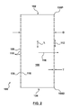
FIG. 2 is a cross-sectional view of the high metal to vessel ratio stent of FIG. 1;
FIG. 3 is an enlarged plan view of a region of the high metal to vessel ratio stent of FIG. 1 in its final configuration in accordance with one embodiment;
FIG. 4 is an enlarged plan view of the region of the high metal to vessel ratio stent of FIG. 3 in its constrained configuration in accordance with one embodiment;
FIG. 5 is an enlarged plan view of the region of the high metal to vessel ratio stent of FIG. 1 in its final configuration in accordance with another embodiment;
FIG. 6 is an enlarged plan view of the region of the high metal to vessel ratio stent of FIG. 5 in its constrained configuration in accordance with one embodiment;
FIG. 7 is an enlarged plan view of the region of the high metal to vessel ratio stent of FIG. 1 in its final configuration in accordance with yet another embodiment;
FIG. 8 is an enlarged plan view of the region of the high metal to vessel ratio stent of FIG. 7 in its constrained configuration in accordance with one embodiment;
FIG. 9 is an enlarged plan view of the region of the high metal to vessel ratio stent of FIG. 1 in its final configuration in accordance with yet another embodiment;
FIG. 10 is a cross-section view of the high metal to vessel ratio stent along the line X-X of FIG. 9 in accordance with one embodiment;
FIG. 11 is an enlarged plan view of the region of the high metal to vessel ratio stent of FIG. 1 in its final configuration in accordance with yet another embodiment;
FIG. 12 is an enlarged plan view of the region of the high metal to vessel ratio stent of FIG. 1 in its final configuration in accordance with yet another embodiment;
FIG. 13 is a perspective view of a high metal to vessel ratio stent in accordance with another embodiment;
FIG. 14 is a cross-sectional view of a vessel assembly including a delivery system including the high metal to vessel ratio stent of FIGS. 1 and 2 in accordance with one embodiment;
FIG. 15 is a cross-sectional view of the vessel assembly including the delivery system at a later stage of deploying the high metal to vessel ratio stent of FIGS. 1 and 2 in accordance with one embodiment;
FIG. 16 is a cross-sectional view of the vessel assembly of FIGS. 14-15 after deployment of the high metal to vessel ratio stent of FIGS. 1 and 2 in accordance with one embodiment; and
FIG. 17 is a cross-sectional view of the vessel assembly of FIG. 16 illustrating tissue ingrowth into the high metal to vessel ratio stent.
In the following description, the same or similar elements are labeled with the same or similar reference numbers.
DETAILED DESCRIPTION
As an overview and in accordance with one embodiment, referring to FIG. 16, a method includes covering ostai 1422, 1424 of branch vessels 1408, 1410 emanating from a main vessel 1404 with a high metal to vessel ratio stent 100. A metal to vessel ratio of high metal to vessel ratio stent 100 is sufficiently high to encourage tissue ingrowth around high metal to vessel ratio stent 100 yet is sufficiently low to ensure perfusion of branch vessels 1408, 1410 through high metal to vessel ratio stent 100. The ingrowth of tissue provides secure fixation and sealing of high metal to vessel ratio stent 100 to main vessel 1404 thus minimizing the risk of endoleaks and migration.
Further, deployment of high metal to vessel ratio stent 100 is relatively simple thus minimizing the complexity and thus risk of deploying high metal to vessel ratio stent 100. More particularly, as the entire high metal to vessel ratio stent 100 is permeable, high metal to vessel ratio stent 100 is deployed without having to rotationally position high metal to vessel ratio stent 100 to be aligned with branch vessels 1408, 1410 as is currently done with deployment of branched and fenestrated devices.
The method further includes covering and excluding an aneurysm 1406 of main vessel 1404 with high metal to vessel ratio stent 100. Referring now to FIGS. 16 and 17 together, the ingrowth of tissue 1702 restricts expansion of aneurysm 1406. In one embodiment, aneurysm 1406 is remodeled and essentially eliminated as illustrated in FIG. 17.
Now in more detail, FIG. 1 is a perspective outline view of a high metal to vessel ratio stent 100, e.g., an abdominal aortic stent, in its final configuration in accordance with one embodiment. FIG. 2 is a cross-sectional view of high metal to vessel ratio stent 100 of FIG. 1. High metal to vessel ratio stent 100 is sometimes called an endoluminal flow disrupting device.
Referring now to FIGS. 1 and 2 together, high metal to vessel ratio stent 100 includes a proximal main opening 102 at a proximal end 100P of high metal to vessel ratio stent 100 and a distal main opening 104 at a distal end 100D of high metal to vessel ratio stent 100.
As used herein, the proximal end of a prosthesis such as high metal to vessel ratio stent 100 is the end closest to the heart via the path of blood flow whereas the distal end is the end furthest away from the heart during deployment. In contrast and of note, the distal end of the delivery system is usually identified to the end that is farthest from the operator (handle) while the proximal end of the delivery system is the end nearest the operator (handle).
For purposes of clarity of discussion, as used herein, the distal end of the delivery system is the end that is farthest from the operator (the end furthest from the handle) while the distal end of the prosthesis is the end nearest the operator (the end nearest the handle), i.e., the distal end of the delivery system and the proximal end of the prosthesis are the ends furthest from the handle while the proximal end of the delivery system and the distal end of the prosthesis are the ends nearest the handle. However, those of skill in the art will understand that depending upon the access location, the prosthesis and delivery system description may be consistent or opposite in actual usage.
High metal to vessel ratio stent 100 is cylindrical and includes a longitudinal axis L. A main lumen 106 is defined by high metal to vessel ratio stent 100 and extends generally parallel to longitudinal axis L and between proximal main opening 102 and distal main opening 104 of high metal to vessel ratio stent 100.
In accordance with this embodiment, high metal to vessel ratio stent 100 has a substantially uniform diameter D. However, in other embodiments, high metal to vessel ratio stent 100 has a non-uniform diameter.
High metal to vessel ratio stent 100 is a semi-permeable barrier made of patterned material 108, e.g., is a dense laser cut metal pattern. High metal to vessel ratio stent 100 includes patterned material 108 and a plurality of holes 110 through which fluid, e.g., blood, can pass. Generally, high metal to vessel ratio stent 100 is permeable, sometimes called porous, to fluid, i.e., fluid can pass through high metal to vessel ratio stent 100 and more particularly, through holes 110. This allows fluid, e.g., blood, to pass through high metal to vessel ratio stent 100 and nourish, e.g., with oxygen and nutrients, the covered vessel wall. In this manner, hypoxia of the covered vessel wall is avoided. Further, high metal to vessel ratio stent 100 is permeable to tissue ingrowth.
Longitudinal direction 112 is the direction along high metal to vessel ratio stent 100 parallel to longitudinal axis L. Circumferential direction 114 is the direction along the circumference of high metal to vessel ratio stent 100 in plane perpendicular to longitudinal axis L of high metal to vessel ratio stent 100. Radial direction 116 is along a radius extending from longitudinal axis L in plane perpendicular to longitudinal axis L of high metal to vessel ratio stent 100.
Generally, there are a plurality, e.g., three or more, of holes 110 arranged in both longitudinal direction 112 as well as circumferential direction 114.
The ratio of material 108 per unit area of high metal to vessel ratio stent 100 is high, e.g., greater than or equal 30%. This ratio is sometimes called the metal to vessel ratio (or metal to artery ratio) as it defines the percent of the vessel covered with material 108 per unit area of the vessel. Stated another way, the percentage of high metal to vessel ratio stent 100 formed by material 108 is high, e.g., greater than or equal to 30%, and the percentage of high metal to vessel ratio stent 100 formed of holes 110 is low, e.g., less than or equal to 70%.
Generally, the metal to vessel ratio is defined as the area occupied by material 108 of high metal to vessel ratio stent 100 for a unit area of high metal to vessel ratio stent 100 when in the final configuration. To illustrate, for an X square centimeter (cm2) area of high metal to vessel ratio stent 100, Y percent is formed of material 108 whereas Z percent is formed of holes 110, where Y+Z=100. Continuing with this example, Y is the metal to vessel ratio expressed as percent.
To give a specific example for a 40% metal to vessel ratio, for a 1.0 square centimeter area of high metal to vessel ratio stent 100, 0.4 square centimeters would be covered by material 108 whereas 0.6 square centimeters would be covered by holes 110. The metal to vessel ratio can be expressed as a fraction, e.g., 0.4 for this example, or as a percentage, e.g., 40% for this example. To convert, the fraction is multiplied by 100 to obtain the percentage.
Although a fixed metal to vessel ratio is set forth, in other embodiments, the metal to vessel ratio of high metal to vessel ratio stent 100 varies in the longitudinal direction 112 and/or in the circumferential direction 114 along high metal to vessel ratio stent 100.
As set forth above, the metal to vessel ratio is defined when high metal to vessel ratio stent 100 is in the final configuration. High metal to vessel ratio stent 100 is in the final configuration when in its final unconstrained expanded state, sometimes called at nominal deployment. More particularly, when the diameter of high metal to vessel ratio stent 100 is approximately equal, e.g., 10% to 20% oversized, to the diameter of the vessel in which high metal to vessel ratio stent 100 is being deployed and high metal to vessel ratio stent 100 is at its natural unconstrained length at this diameter, high metal to vessel ratio stent 100 is in its final state. Generally, once deployed within the vessel at its natural unconstrained length as discussed below, high metal to vessel ratio stent 100 is in the final configuration.
The final configuration should be contrasted to the constrained configuration of high metal to vessel ratio stent 100. High metal to vessel ratio stent 100 is in a constrained configuration when high metal to vessel ratio stent 100 is constrained to a reduced diameter, e.g., within a delivery sheath. Further, high metal to vessel ratio stent 100 is in a constrained configuration when high metal to vessel ratio stent 100 is constrained to a reduced or expanded length, e.g., by longitudinally compressing or expanding high metal to vessel ratio stent 100. When in the constrained configuration, either in length, diameter, or both, holes 110 are collapsed resulting in a much higher metal to vessel ratio for high metal to vessel ratio stent 100 than when high metal to vessel ratio stent 100 and is in its final configuration.
As discussed further below, e.g., in reference to FIGS. 14-17, the metal to vessel ratio of high metal to vessel ratio stent 100 is sufficiently high to encourage tissue ingrowth around high metal to vessel ratio stent 100. However, the metal to vessel ratio of high metal to vessel ratio stent 100 is sufficiently low to ensure adequate perfusion of branch vessel(s) through high metal to vessel ratio stent 100.
Generally, the metal to vessel ratio of high metal to vessel ratio stent 100 is within the range of 30 percent to 80 percent (30-80%), more suitably within the range of 35 percent to 60 percent (35-60%). In one particular embodiment, the metal to vessel ratio is 40 percent (40%).
In one embodiment, high metal to vessel ratio stent 100 is formed of balloon expandable and/or self-expanding metal, e.g., e.g., formed of Nitinol or stainless steel. In one embodiment, high metal to vessel ratio stent 100 is a laser cut, etched, or wire formed stent. For example, a cylindrical tube of metal, e.g., Nitinol, is cut with a laser and/or by etching to form holes 110 therein thus forming high metal to vessel ratio stent 100. The cylindrical tube of metal can be formed from a metal sheet that is bent and welded in one embodiment.
As illustrated in FIG. 2, high metal to vessel ratio stent 100 has a thickness T, e.g., equal to the thickness of the cylindrical tube from which high metal to vessel ratio stent 100 is formed. Thickness T is the distance between the inner cylindrical surface 118 and the outer cylindrical surface 120 of high metal to vessel ratio stent 100.
FIG. 3 is an enlarged plan view of the region 122 of high metal to vessel ratio stent 100 of FIG. 1 in its final configuration in accordance with one embodiment. Referring now to FIG. 3, high metal to vessel ratio stent 100 includes a plurality of serpentine rings 302 connected together.
Serpentine rings 302 includes a zigzag pattern, sometimes called a sinusoidal or an alternating repeating pattern. More particularly, each serpentine ring 302 includes a repeating pattern of proximal apexes 304 and distal apexes 306 connected by struts 308. Proximal apexes 304 and distal apexes 306 are sometimes called peaks and valleys, respectively, or crowns.
Proximal apexes 304 define the proximal edge 310 of each serpentine ring 302. Proximal edge 310 is an imaginary circle at proximal apexes 304 in a plane perpendicular to longitudinal axis L of high metal to vessel ratio stent 100.
Similarly, distal apexes 306 define the distal edge 312 of each serpentine ring 302. Distal edge 312 is an imaginary circle at distal apexes 306 in a plane perpendicular to longitudinal axis L of high metal to vessel ratio stent 100. Struts 308 generally extend between proximal edge 310 and distal edge 312 of each serpentine ring 302.
To illustrate, serpentine rings 302 include a first serpentine ring 302A. Serpentine ring 302A includes a proximal edge 310 at proximal apexes 304, a distal edge 312 at distal apexes 306, and struts 308 extending between proximal edge 310 and distal edge 312.
To further illustrate, serpentine ring 302A includes a first distal apex 306A and a second distal apex 306B of the plurality of distal apexes 306 of serpentine ring 302A. Serpentine ring 302A includes a first proximal apex 304A of the plurality of proximal apexes 304 of serpentine ring 302A. Serpentine ring 302A further includes a first strut 308A and a second strut 308B of the plurality of struts 308 of serpentine ring 302A. Distal apex 306A is connected to proximal apex 304A by strut 308A. Proximal apex 304A is connected to distal apex 306B by strut 308B.
Each proximal apex 304 has two respective struts 308 extending therefrom. To illustrate, proximal apex 304A has struts 308A, 308B extending therefrom, which are thus the two respective struts 308 of proximal apex 304A.
Each proximal apex 304 includes an extrados surface 314 and an intrados surface 316. Extrados surface 314 is the exterior surface of the curve of each proximal apex 304. In contrast, intrados surface 316 is the interior surface of the curve of a proximal apex 304.
Further, with respect to proximal apexes 304, each strut 308 includes an exterior radial surface 318 and an interior radial surface 320. Exterior radial surfaces 318 are further outward, or exterior, to interior radial surfaces 320 in circumferential direct 114 with respect to the respective proximal apex 304. Exterior radial surfaces 318 and interior radial surfaces 320 are parallel to and extend in radial direction 116 from inner cylindrical surface 118 to outer cylindrical surface 120 of high metal to vessel ratio stent 100.
Generally, exterior radial surfaces 318 are continuous with extrados surfaces 314 and interior radial surfaces 320 are continuous with intrados surfaces 316.
To illustrate, with respect to proximal apex 304A, strut 308A includes an exterior radial surface 318A and an interior radial surface 320A. Further, with respect to proximal apex 304A, strut 308B includes an exterior radial surface 318B and an interior radial surface 320B.
Proximal apexes 304 of serpentine rings 302 are directly connected to distal apexes 306 of the adjacent proximal serpentine ring 302. To illustrate, serpentine rings 302 include a second serpentine ring 302B. Proximal apexes 304 of serpentine ring 302B are connected to distal apexes 306 of serpentine ring 302A. Note serpentine ring 302A is proximal to serpentine ring 302B.
Of course, the proximal apexes 304 of the most proximal of serpentine rings 302 are unconnected to another serpentine ring and define the proximal end 100P of high metal to vessel ratio stent 100. Similarly, the distal apexes 306 of the most distal of serpentine rings 302 are unconnected to another serpentine ring and define the distal end 100D of high metal to vessel ratio stent 100.
To increase the metal to vessel ratio of high metal to vessel ratio stent 100, each strut 308 includes a plurality of fingers 322. Fingers 322 increase the surface area of material 108 as compared to the area of serpentine rings 302 alone.
Fingers 322 are protrusions that protrude from struts 308 in a direction along the imaginary cylinder of high metal to vessel ratio stent 100. More particularly, each finger 322 includes a knuckle 324 directly attached to a strut 308 and a tip 326. Each finger 322 extends from knuckle 324 and strut 308 to tip 326, where the finger 322 ends.
To illustrate, a first finger 322A of the plurality of fingers 322 is attached to strut 308A. Finger 322A includes a knuckle 324 directly attached to strut 308A and a tip 326.
In accordance with this embodiment, each strut 308 includes a plurality of fingers 322 on both the exterior radial surface 318 and the interior radial surface 320. To illustrate, strut 308A includes fingers 322 on exterior radial surface 318A and interior radial surface 320A.
In accordance with this embodiment, with respect to a proximal apex 304, the pattern of fingers 322 on an interior radial surface 320 of a first strut 308 of the two respective struts 308 of the proximal apex 304 is the same, or approximately the same, as the pattern of fingers 322 on an exterior radial surface 318 of a second strut 308 of the two respective struts 308 of the proximal apex 304.
To illustrate, with respect to proximal apex 304A, the pattern of fingers 322 on interior radial surface 320A (or 320B) of a first strut 308A (or 308B) of the two respective struts 308A, 308B of proximal apex 304A is the same as the pattern of fingers 322 on exterior radial surface 318B (or 318A) of a second strut 308B of the two respective struts 308A, 308B of proximal apex 304A, respectively.
With respect to a proximal apex 304, the pattern of fingers 322 on an interior radial surface 320 of a first strut 308 of the two respective struts 308 of the proximal apex 304 is different than, and interdigitated with, the pattern of fingers 322 on an interior radial surface 320 of a second strut 308 of the two respective struts 308 of the proximal apex 304.
To illustrate, with respect to proximal apex 304A, the pattern of fingers 322 on interior radial surface 320A of a first strut 308A of the two respective struts 308A, 308B of proximal apex 304A is different than, and interdigitated with, the pattern of fingers 322 on interior radial surface 320B of a second strut 308B of the two respective struts 308A, 308B of proximal apex 304A, respectively.
Generally, fingers 322 on directly adjacent radial surfaces of directly adjacent struts 308 are interdigitated with one another. To illustrate, fingers 322 on exterior radial surface 318B of strut 308B are interdigitated with fingers 322 on a directly adjacent exterior radial surface 318C of the directly adjacent strut 308C.
By having fingers 322 on directly adjacent radial surfaces of directly adjacent struts 308 be interdigitated, e.g., interlocked like the fingers of folded hands when in the constrained configuration, high metal to vessel ratio stent 100 can be radially collapsed to an extremely small diameter.
As discussed above, high metal to vessel ratio stent 100 includes a plurality of holes 110. In accordance with this embodiment, each hole 110 is defined by a stent cell 328 of high metal to vessel ratio stent 100.
More particularly, stent cell 328 is defined by: (1) a proximal apex 304 of a first serpentine ring 302; (2) the respective struts 308 of element (1); (3) the respective distal apexes 306 connected to element (2); (4) the proximal apexes 304 of the next serpentine ring 302 that are connected to element (3); (5) the directly adjacent struts 308 that are connected to element (4); (6) the distal apex 306 connected to element (5), and the fingers 322 protruding into the respective hole 110 from elements (2), (5).
FIG. 4 is an enlarged plan view of the region 122 of high metal to vessel ratio stent 100 of FIG. 3 in its constrained configuration in accordance with one embodiment. FIG. 4 corresponds to the view of FIG. 3, however, in FIG. 4, high metal to vessel ratio stent 100 is in the constrained, e.g., radially collapsed, configuration, whereas in FIG. 3, high metal to vessel ratio stent 100 is in the final, e.g., radially expanded, configuration.
As illustrated in FIG. 4, when in the constrained configuration, fingers 322 on directly adjacent radial surfaces of directly adjacent struts 308 fit one within another, i.e., are interdigitated. This allows high metal to vessel ratio stent 100 to be radially collapsed to an extremely small diameter.
FIG. 5 is an enlarged plan view of the region 122 of high metal to vessel ratio stent 100 of FIG. 1 in its final configuration in accordance with another embodiment. Region 122 as illustrated in FIG. 5 is similar to region 122 as illustrated in FIG. 3 and only the significant differences are discussed below.
Referring now to FIG. 5, high metal to vessel ratio stent 100 includes serpentine rings 302 including serpentine rings 302A, 302B, proximal apexes including proximal apex 304A, distal apexes 306 including distal apexes 306A, 306B, struts 308 including struts 308A, 308B, 308C, proximal edges 310, distal edges 312, extrados surfaces 314, intrados surfaces 316, exterior radial surfaces 318 including exterior radial surfaces 318A, 318B, 318C, internal radial surfaces 320 including internal radial surfaces 320A, 320B as discussed above in relation to FIGS. 3, 4.
In accordance with this embodiment, to increase the metal to vessel ratio of high metal to vessel ratio stent 100, high metal to vessel ratio stent 100 includes projections 502. More particularly, a projection 502 is attached to each proximal apex 304 and protrudes distally therefrom. Similarly, a projection 502 is attached to each distal apex 306 and protrudes proximal therefrom.
Projections 502 including stems 504 and petals 506. Stems 504 include serpentine ring attachment ends 508 and petal attachment ends 510. Serpentine ring attachment ends 508 are directly attached to a serpentine ring 302, i.e., a proximal apex 304 or a distal apex 306. Petals 506 are directly attached to petal attachment ends 510 of stems 504.
In accordance with this embodiment, each projection 502 includes two petals 506. Petals 506 are located in circumferential direction 114 approximately between directly adjacent apexes of a serpentine ring 302.
To illustrate, a first projection 502A is attached to proximal apex 304A of serpentine ring 302A and protrudes distally therefrom. Similarly, a second projection 502B is attached to a distal apex 306 of serpentine ring 302B and protrudes proximal therefrom.
To further illustrate, petals 506 of first projection 502A are located in circumferential direction 114 between directly adjacent distal apexes 306A, 306B of serpentine ring 302A. To further illustrate, petals 506 of second projection 502B are located in circumferential direction 114 between directly adjacent proximal apexes 304 of serpentine ring 302B.
As illustrated by dashed lines on the projection 502 at the upper right of FIG. 5, in one embodiment, to further increase the metal to vessel ratio of high metal to vessel ratio stent 100, each stem 504 includes a plurality of fingers 322 attached thereto. Fingers 322, and the number thereof, are optional, and generally are provided to obtain a desired metal to vessel ratio of high metal to vessel ratio stent 100.
As discussed above, high metal to vessel ratio stent 100 includes a plurality of holes 110. In accordance with this embodiment, each hole 110 is defined by a stent cell 512 of high metal to vessel ratio stent 100.
More particularly, stent cell 512 is defined by: (1) a proximal apex 304 of a first serpentine ring 302; (2) the respective struts 308 of element (1); (3) the respective distal apexes 306 connected to element (2); (4) the proximal apexes 304 of the next serpentine ring 302 that are connected to element (3); (5) the directly adjacent struts 308 that are connected to element (4); (6) the distal apex 306 connected to element (5), and the projections 502 protruding into the respective hole 110 from elements (1), (6).
Stems 504 extend longitudinally between adjacent struts 308 where the spacing between struts 308 is relatively small. In contrast, petals 506 are located between adjacent struts 308 where the spacing between struts 308 is relatively large. This allows high metal to vessel ratio stent 100 to be radially collapsed to an extremely small diameter as illustrated in FIG. 6.
FIG. 6 is an enlarged plan view of the region 122 of high metal to vessel ratio stent 100 of FIG. 5 in its constrained configuration in accordance with one embodiment. FIG. 6 corresponds to the view of FIG. 5, however, in FIG. 6, high metal to vessel ratio stent 100 is in the constrained, e.g., radially collapsed, configuration, whereas in FIG. 5, high metal to vessel ratio stent 100 is in the final, e.g., radially expanded, configuration.
As illustrated in FIG. 6, when in the constrained configuration, projections 502 are collapsed between adjacent struts 308. This allows high metal to vessel ratio stent 100 to be radially collapsed to an extremely small diameter.
FIG. 7 is an enlarged plan view of the region 122 of high metal to vessel ratio stent 100 of FIG. 1 in its final configuration in accordance with yet another embodiment. Region 122 as illustrated in FIG. 7 is similar to region 122 as illustrated in FIG. 5 and only the significant differences are discussed below.
Referring now to FIG. 7, high metal to vessel ratio stent 100 includes serpentine rings 302 including serpentine rings 302A, 302B, proximal apexes including proximal apex 304A, distal apexes 306 including distal apexes 306A, 306B, struts 308 including struts 308A, 308B, 308C, projections 502 including projections 502A, 502B, stems 504 and petals 506.
In accordance with this embodiment, to further increase the ability to radially collapse high metal to vessel ratio stent 100, high metal to vessel ratio stent 100 includes serpentine ring connectors 702. More particularly, proximal apexes 304 of serpentine rings 302 are connected to distal apexes 306 of the adjacent proximal serpentine ring 302 by serpentine ring connectors 702. Serpentine ring connectors 702 are straight segments extending in longitudinal direction 112 in accordance with this embodiment.
As discussed above, high metal to vessel ratio stent 100 includes a plurality of holes 110. In accordance with this embodiment, each hole 110 is defined by a stent cell 712 of high metal to vessel ratio stent 100.
More particularly, stent cell 712 is defined by: (1) a proximal apex 304 of a first serpentine ring 302; (2) the respective struts 308 of element (1); (3) the respective distal apexes 306 connected to element (2); (4) the serpentine ring connectors 702 connected to element (3); (5) the proximal apexes 304 of the next serpentine ring 302 that are connected to element (4); (6) the directly adjacent struts 308 that are connected to element (5); (7) the distal apex 306 connected to element (6), and the projections 502 protruding into the respective hole 110 from elements (1), (7).
Serpentine ring connectors 702 space adjacent serpentine rings 302 from each other in longitudinal direction 112. In accordance with this embodiment, stems 504 of projections 502 extend longitudinally into this space between adjacent serpentine rings 302. Accordingly, petals 506 of projections 502 are located in circumferential direction 114 between directly adjacent serpentine ring connectors 702.
By using serpentine ring connectors 702 to space apart serpentine rings 302 and placing petals 506 within this space, high metal to vessel ratio stent 100 can be radially collapsed to an extremely small diameter as illustrated in FIG. 8.
FIG. 8 is an enlarged plan view of the region 122 of high metal to vessel ratio stent 100 of FIG. 7 in its constrained configuration in accordance with one embodiment. FIG. 8 corresponds to the view of FIG. 7, however, in FIG. 8, high metal to vessel ratio stent 100 is in the constrained, e.g., radially collapsed, configuration, whereas in FIG. 7, high metal to vessel ratio stent 100 is in the final, e.g., radially expanded, configuration.
As illustrated in FIG. 8, when in the constrained configuration, petals 506 are collapsed between serpentine ring connectors 702. This allows high metal to vessel ratio stent 100 to be radially collapsed to an extremely small diameter.
FIG. 9 is an enlarged plan view of the region 122 of high metal to vessel ratio stent 100 of FIG. 1 in its final configuration in accordance with yet another embodiment. Region 122 as illustrated in FIG. 9 is similar to region 122 as illustrated in FIG. 3 and only the significant differences are discussed below.
Referring now to FIG. 9, high metal to vessel ratio stent 100 includes serpentine rings 302, proximal apexes 304, distal apexes 306, and struts 308.
In accordance with this embodiment, to increase the metal to vessel ratio of high metal to vessel ratio stent 100, high metal to vessel ratio stent 100 includes serpentine ring connectors 902. More particularly, serpentine rings 302 are connected to one another by serpentine ring connectors 902.
Serpentine ring connectors 902 are straight segments, e.g., thin flexible beams, extending in longitudinal direction 112 in accordance with this embodiment. However, in other embodiments, serpentine ring connectors 902 are angled, curved, or otherwise nonlinear connectors and can be oriented in any direction, e.g., longitudinally, diagonally, crossing, or other direction. Further, serpentine ring connectors 902 can be attached to serpentine rings 302 at proximal apexes 304, distal apexes 306, and to struts 308.
By providing a particular number of serpentine ring connectors 902, a desired metal to vessel ratio of high metal to vessel ratio stent 100 is obtained.
FIG. 10 is a cross-section view of high metal to vessel ratio stent 100 along the line X-X of FIG. 9 in accordance with one embodiment. As illustrated in FIG. 10, in accordance with this embodiment, serpentine ring connectors 902 are physically attached, e.g., by welding, to serpentine rings 302. Further, the thickness of serpentine rings 302 is greater than the thickness of serpentine ring connectors 902.
FIG. 11 is an enlarged plan view of the region 122 of high metal to vessel ratio stent 100 of FIG. 1 in its final configuration in accordance with yet another embodiment. Region 122 as illustrated in FIG. 11 is similar to region 122 as illustrated in FIG. 3 and only the significant differences are discussed below.
Referring now to FIG. 11, high metal to vessel ratio stent 100 includes serpentine rings 302, proximal apexes 304, distal apexes 306, and struts 308.
In accordance with this embodiment, to increase the metal to vessel ratio of high metal to vessel ratio stent 100, high metal to vessel ratio stent 100 includes a high number of serpentine rings 302 with short lengths. More particularly, each serpentine ring 302 includes 20-30 proximal apexes 304 and correspondingly, 20-30 distal apexes 306.
FIG. 12 is an enlarged plan view of the region 122 of high metal to vessel ratio stent 100 of FIG. 1 in its final configuration in accordance with yet another embodiment. Referring now to FIG. 12, high metal to vessel ratio stent 100 includes diamond rings 1202 connected together. Diamond rings 1202 define stent cells 1204. By providing a plurality of stent cells 1204, a high metal to vessel ratio is achieved.
Further, serpentine rings 302 as illustrated in FIG. 11 can be combined with diamond rings 1202 as illustrated in FIG. 12 to form high metal to vessel ratio stent 100 in accordance with other embodiments. The amplitude of the serpentine rings 302 and/or diamond rings 1202 can be varied.
FIG. 13 is a perspective view of a high metal to vessel ratio stent 1300 in accordance with another embodiment. Referring now to FIG. 13, high metal to vessel ratio stent 1300 is a coil stent, i.e., a coil of material.
High metal to vessel ratio stent 1300 includes a plurality of windings 1302. In accordance with this embodiment, by controlling how close the windings 1302 are, i.e., by longitudinally packing or stretching high metal to vessel ratio stent 1300, the metal to vessel ratio of high metal to vessel ratio stent 1300 can be controlled. Although delivery of high metal to vessel ratio stent 100 of FIGS. 1 and 2 is discussed below in reference to FIGS. 14-18, the discussion is equally applicable to delivery of high metal to vessel ratio stent 1300 of FIG. 13.
FIG. 14 is a cross-sectional view of a vessel assembly 1400 including a delivery system 1402 including high metal to vessel ratio stent 100 of FIGS. 1 and 2 in accordance with one embodiment. FIG. 15 is a cross-sectional view of vessel assembly 1400 including delivery system 1402 at a later stage of deploying high metal to vessel ratio stent 100 of FIGS. 1 and 2 in accordance with one embodiment.
Referring now to FIGS. 14 and 15 together, a main vessel 1404, e.g., the aorta, includes an aneurysm 1406. High metal to vessel ratio stent 100, sometimes called a prosthesis, is deployed into main vessel 1404 to exclude aneurysm 1406 using delivery system 1402.
Emanating from main vessel 1404 is a first branch vessel 1408 and a second branch vessel 1410, sometimes called visceral branches of the abdominal aorta. The location of branch vessels 1408, 1410 vary from patient to patient. Examples of branch vessels 1408, 1410 include the renal arteries (RA), the superior mesenteric artery (SMA), the brachiocephalic artery, the left subclavian artery, the left common carotid, the celiac trunk, and the hypogastric artery.
Delivery system 1402 is advanced to the location of aneurysm 1406, e.g., over a guidewire 1412, for example as illustrated in FIG. 14. Delivery system 1402 includes a tapered tip 1414 that is flexible and able to provide trackability in tight and tortuous vessels. Tapered tip 1414 includes a lumen 1416 allowing for passage of guidewire 1412 in accordance with this embodiment. In one embodiment, delivery system 1402 includes radiopaque marker(s) that allow visualization of delivery system 1402.
To deploy high metal to vessel ratio stent 100, an inner member 1418 of delivery system 1402 including tapered tip 1414 mounted thereon is held stationary while an outer sheath 1420 of delivery system 1402 is withdrawn, for example, as illustrated in FIG. 15. High metal to vessel ratio stent 100 is radially constrained by outer sheath 1420 around inner member 1418. Inner member 1418 includes a stent stop or other features to prevent high metal to vessel ratio stent 100 from moving back as outer sheath 1420 is withdrawn.
As outer sheath 1420 is withdrawn, high metal to vessel ratio stent 100 is gradually exposed from proximal end 100P to distal end 100D of high metal to vessel ratio stent 100. The exposed portion of high metal to vessel ratio stent 100 radially expands to be in conforming surface contact with main vessel 1404. More particularly, high metal to vessel ratio stent 100 opposes the walls of main vessel 1404 thus securing high metal to vessel ratio stent 100 in place.
In one embodiment, high metal to vessel ratio stent 100 is self-expanding and thus self expands upon being released from outer sheath 1420. However, in other embodiments, high metal to vessel ratio stent 100 is expanded with a balloon or other expansion device.
Although a particular delivery system 1402 is illustrated in FIGS. 14, 15 and discussed above, in light of this disclosure, those of skill in the art will understand that any one of a number of delivery systems can be used to deploy high metal to vessel ratio stent 100 and the particular delivery system used is not essential to this embodiment.
FIG. 16 is a cross-sectional view of vessel assembly 1400 of FIGS. 14-15 after deployment of high metal to vessel ratio stent 100 of FIGS. 1 and 2 in accordance with one embodiment. Referring now to FIG. 16, high metal to vessel ratio stent 100 is in conforming surface contact with main vessel 1404. High metal to vessel ratio stent 100 is deployed such that high metal to vessel ratio stent 100 covers, sometimes called jails, ostai (plural of ostium) 1422, 1424 of branch vessels 1408, 1410, respectively.
However, as high metal to vessel ratio stent 100 is permeable, blood flows from main vessel 1404 through high metal to vessel ratio stent 100 and into branch vessels 1408, 1410 thus perfusing branch vessels 1408, 1410. In one embodiment, branch vessels 1408, 1410 are continuously perfused during the entire procedure of deploying high metal to vessel ratio stent 100.
Further, deployment of high metal to vessel ratio stent 100 is relatively simple thus minimizing the complexity and thus risk of deploying high metal to vessel ratio stent 100. More particularly, as the entire high metal to vessel ratio stent 100 is permeably, high metal to vessel ratio stent 100 is deployed without having to rotationally position high metal to vessel ratio stent 100 to be aligned with branch vessels 1408, 1410.
Further, high metal to vessel ratio stent 100 is deployed with fixation and sealing to main vessel 1404 superior to aneurysm 1406, e.g., to healthy tissue of main vessel 1404 adjacent branch vessels 1408, 1410. This minimizes the risk of migration of high metal to vessel ratio stent 100. Further, this allows fixation and sealing of high metal to vessel ratio stent 100 to healthy tissue even when aneurysm 1406 has a short neck, i.e., when the distance between aneurysm 1406 and branch vessels 1408, 1410 is relatively small, as well as when aneurysm 1406 has a highly angulated neck.
Further, high metal to vessel ratio stent 100 covers and excludes aneurysm 1406. More particularly, once high metal to vessel ratio stent 100 is anchored within main vessel 1404, blood flows through main lumen 106 thus excluding aneurysm 1406.
Further, high metal to vessel ratio stent 100 is deployed with fixation and sealing to main vessel 1404 inferior to aneurysm 1406, e.g., to healthy tissue of main vessel 1404. This further facilitates exclusion of aneurysm 1406 while at the same time minimizes the risk of migration of high metal to vessel ratio stent 100.
In other examples, high metal to vessel ratio stent 100 is a bifurcated stent, e.g., high metal to vessel ratio stent 100 is bifurcated to extend into the iliac arteries.
As discussed above, by forming high metal to vessel ratio stent 100 to have a high metal to vessel ratio, branch vessels 1408, 1410 are adequately perfused through high metal to vessel ratio stent 100 while at the same time tissue ingrowth of main vessel 1404 into high metal to vessel ratio stent 100 is encouraged.
FIG. 17 is a cross-sectional view of the vessel assembly of FIG. 16 illustrating tissue 1702 ingrowth into high metal to vessel ratio stent 100. For example, FIG. 17 illustrates ingrowth of tissue 1702 after a period of time, e.g., weeks or months, after the deployment of high metal to vessel ratio stent 100 into main vessel 1404.
Referring now to FIGS. 16 and 17 together, once deployed, high metal to vessel ratio stent 100 includes a fixation region 1704 and a perfusion region 1706. Fixation region 1704 is the region of high metal to vessel ratio stent 100 in direct contact with main vessel 1404. Perfusion region 1706 is the region of high metal to vessel ratio stent 100 covering ostium 1422 of branch vessel 1408 and covering ostium 1424 of branch vessel 1410.
After deployment of high metal to vessel ratio stent 100, tissue 1702 of main vessel 1404 grows through holes 110 of fixation region 1704 of high metal to vessel ratio stent 100. Tissue 1702 encases, sometimes called encloses or encapsulates, material 108 of fixation region 1704 of high metal to vessel ratio stent 100.
This ingrowth of tissue 1702 provides secure fixation and sealing of high metal to vessel ratio stent 100 to main vessel 1404. By providing secure fixation and sealing of high metal to vessel ratio stent 100 to main vessel 1404, the risk of endoleaks into aneurysm 1406 and migration of high metal to vessel ratio stent 100 is minimized. Further, the ingrowth of tissue 1702 restricts expansion of aneurysm 1406. In one embodiment, aneurysm 1406 is remodeled and essentially eliminated as illustrated in FIG. 17.
Further, as illustrated in FIG. 17, tissue 1702 does not grow over perfusion region 1706 of high metal to vessel ratio stent 100. More particularly, blood flows as indicated by the arrows 1708 through holes 110 of perfusion region 1706 to perfuse branch vessels 1408, 1410. Further, this blood flow prevents tissue overgrowth on perfusion region 1706 thus avoiding occlusion of branch vessels 1408, 1410 and the associated complications.
In one embodiment, to encourage tissue ingrowth, high metal to vessel ratio stent 100 includes a surface treatment. Illustratively, a thin layer of metal is applied, e.g., by sputtering, physical vapor deposition (PVD), plasma enhanced chemical vapor deposition (PECVD), or other application technique, to high metal to vessel ratio stent 100 to encourage tissue ingrowth.
Examples of suitable metals include gold, stainless steel, titanium oxide, and/or copper, or combinations thereof are applied to high metal to vessel ratio stent 100 to encourage tissue ingrowth.
In another embodiment, the surface treatment includes roughening the surface of high metal to vessel ratio stent 100 to encourage tissue ingrowth. For example, the surface is roughened to have a roughness average (RA) of greater than 1.0 micron (μm). The surface can be roughened by plasma etching, laser etching, sandblasting, a selective etch to preferentially etch one component of high metal to vessel ratio stent 100 over another, or other surface roughening technique.
In yet another embodiment, the surface treatment includes a growth factor applied to high metal to vessel ratio stent 100 to enhance tissue ingrowth into high metal to vessel ratio stent 100. Examples of growth factors include vascular endothelial growth factor (VEGF), platelet-derived growth factor (PDGF), plated-derived epidermal growth factor (PDEGF), fibroblast growth factors (FGFs), basic fibroblast growth factor (bFGF), transforming growth factor-beta (TGF-.beta.), platelet-derived angiogenesis growth factor (PDAF) and autologous platelet gel (APG).
Another example of growth factors include bioactive materials, e.g., a bioactive compound, drug, therapeutic agent or composition having a biological effect in an animal. Bioactive materials include small molecules, peptides, proteins, hormones, DNA or RNA fragments, genes, cells, genetically-modified cells, cell growth promoting compositions, inhibitors of matrix metalloproteinase, fatty acids and autologous platelet gel.
This disclosure provides exemplary embodiments. The scope is not limited by these exemplary embodiments. Numerous variations, whether explicitly provided for by the specification or implied by the specification or not, such as variations in structure, dimension, type of material and manufacturing process may be implemented by one of skill in the art in view of this disclosure.

Claims (29)

What is claimed is:
1. A prosthesis comprising:
a plurality of serpentine rings comprising struts;
fingers protruding from the struts, wherein a metal to vessel ratio of the prosthesis when in a final configuration is within the range of 30 percent to 80 percent such as to encourage tissue ingrowth around the prosthesis while allowing perfusion of a branch vessel through walls the prosthesis.
2. The prosthesis of claim 1 wherein the metal to vessel ratio is within the range of 35 percent to 60 percent.
3. The prosthesis of claim 1 wherein the serpentine rings comprise proximal apexes, distal apexes, and struts connecting the proximal apexes and the distal apexes.
4. The prosthesis of claim 3 wherein each proximal apex has two respective struts extending therefrom.
5. The prosthesis of claim 4 wherein, with respect to a proximal apex, each strut comprises an exterior radial surface and an interior radial surface.
6. The prosthesis of claim 5 wherein the exterior radial surface is outward to the interior radial surface in a circumferential direction with respect to the proximal apex.
7. The prosthesis of claim 5 wherein the fingers comprise knuckles and tips, the knuckles being directly attached to the struts.
8. The prosthesis of claim 5 wherein each strut comprises the fingers on both the exterior radial surface and the interior radial surface.
9. The prosthesis of claim 8 wherein a pattern of the fingers on an interior radial surface of a first strut of the two respective struts of the proximal apex is the same as the pattern of fingers on an exterior radial surface of a second strut of the two respective struts of the proximal apex.
10. The prosthesis of claim 8 wherein a pattern of the fingers on an interior radial surface of a first strut of the two respective struts of the proximal apex is different than, and interdigitated with, the pattern of fingers on an interior radial surface of a second strut of the two respective struts of the proximal apex.
11. The prosthesis of claim 1 wherein the proximal apexes of the serpentine rings are directly connected to the distal apexes of the adjacent proximal serpentine ring.
12. The prosthesis of claim 1 further comprising:
a surface treatment to encourage the tissue ingrowth.
13. The prosthesis of claim 12
wherein the surface treatment comprises a metal.
14. The prosthesis of claim 12
wherein the surface treatment comprises roughening the prosthesis.
15. The prosthesis of claim 12 wherein the surface treatment comprises a growth factor.
16. A prosthesis comprising:
a plurality of serpentine rings comprising proximal apexes and distal apexes;
projections projecting from the proximal apexes and the distal apexes, wherein the projections comprise stems and petals.
17. The prosthesis of claim 16 wherein a metal to vessel ratio of the prosthesis when in a final configuration is within the range of 30 percent to 80 percent such as to encourage tissue ingrowth around the prosthesis while ensuring perfusion of a branch vessel through walls of the prosthesis.
18. The prosthesis of claim 16 wherein the stems comprise serpentine ring attachment ends directly connected to the proximal apexes and the distal apexes.
19. The prosthesis of claim 18 wherein the stems further comprise petal attachment ends, the petals being directly attached to the petal attachment ends.
20. The prosthesis of claim 16 wherein each projection comprises two petals.
21. The prosthesis of claim 16 wherein the petals are located in a circumferential direction between directly adjacent apexes of a serpentine ring.
22. The prosthesis of claim 16 wherein the projections further comprise fingers on the stems.
23. The prosthesis of claim 16 wherein the proximal apexes of the serpentine rings are connected to the distal apexes of the adjacent proximal serpentine rings by serpentine ring connectors.
24. The prosthesis of claim 23 wherein the serpentine ring connectors extend in a longitudinal direction.
25. The prosthesis of claim 23 wherein the petals are located in a circumferential direction between directly adjacent serpentine ring connectors.
26. A prosthesis comprising:
a plurality of serpentine rings;
serpentine ring connectors connecting the serpentine rings to one another, wherein a metal to vessel ratio of the prosthesis when in the final configuration is within the range of 30% to 80% such as to encourage tissue ingrowth around the prosthesis while allowing perfusion of a branch vessel through walls of the prosthesis.
27. The prosthesis of claim 26 wherein a thickness of the serpentine rings is greater than a thickness of the serpentine ring connectors.
28. The prosthesis of claim 26 wherein the serpentine ring connectors are welded to the serpentine rings.
29. The prosthesis of claim 26, wherein in the metal to vessel ratio is within the range of 35% to 60%.
US13/430,942 2012-03-27 2012-03-27 High metal to vessel ratio stent and method Active 2033-01-20 US9005270B2 (en)

Priority Applications (4)

Application Number Priority Date Filing Date Title
US13/431,732 US8911490B2 (en) 2012-03-27 2012-03-27 Integrated mesh high metal to vessel ratio stent and method
US13/430,942 US9005270B2 (en) 2012-03-27 2012-03-27 High metal to vessel ratio stent and method
EP13708292.1A EP2830547B1 (en) 2012-03-27 2013-02-16 High metal to vessel ratio stent
PCT/US2013/026547 WO2013148012A1 (en) 2012-03-27 2013-02-16 High metal to vessel ratio stent and method

Applications Claiming Priority (1)

Application Number Priority Date Filing Date Title
US13/430,942 US9005270B2 (en) 2012-03-27 2012-03-27 High metal to vessel ratio stent and method

Related Child Applications (1)

Application Number Title Priority Date Filing Date
US13/431,732 Continuation-In-Part US8911490B2 (en) 2012-03-27 2012-03-27 Integrated mesh high metal to vessel ratio stent and method

Publications (2)

Publication Number Publication Date
US20130261728A1 US20130261728A1 (en) 2013-10-03
US9005270B2 true US9005270B2 (en) 2015-04-14

Family

ID=47843409

Family Applications (1)

Application Number Title Priority Date Filing Date
US13/430,942 Active 2033-01-20 US9005270B2 (en) 2012-03-27 2012-03-27 High metal to vessel ratio stent and method

Country Status (3)

Country Link
US (1) US9005270B2 (en)
EP (1) EP2830547B1 (en)
WO (1) WO2013148012A1 (en)

Cited By (11)

* Cited by examiner, † Cited by third party
Publication number Priority date Publication date Assignee Title
USD755384S1 (en) 2014-03-05 2016-05-03 Edwards Lifesciences Cardiaq Llc Stent
US9681951B2 (en) 2013-03-14 2017-06-20 Edwards Lifesciences Cardiaq Llc Prosthesis with outer skirt and anchors
US9717591B2 (en) 2009-12-04 2017-08-01 Edwards Lifesciences Corporation Prosthetic valve for replacing mitral valve
US9730791B2 (en) 2013-03-14 2017-08-15 Edwards Lifesciences Cardiaq Llc Prosthesis for atraumatically grasping intralumenal tissue and methods of delivery
US9974669B2 (en) 2005-11-10 2018-05-22 Edwards Lifesciences Cardiaq Llc Percutaneous heart valve
US10028848B2 (en) 2011-12-06 2018-07-24 Aortic Innovations, Llc Device for endovascular aortic repair and method of using the same
US10166097B2 (en) 2009-09-29 2019-01-01 Edwards Lifesciences Cardiaq Llc Replacement heart valve and method
US10350062B2 (en) 2016-07-21 2019-07-16 Edwards Lifesciences Corporation Replacement heart valve prosthesis
US10888414B2 (en) 2019-03-20 2021-01-12 inQB8 Medical Technologies, LLC Aortic dissection implant
US11065096B2 (en) 2017-10-12 2021-07-20 Loyola University Chicago Thromboembolic protective flow-diverting, common carotid to external carotid intravascular stent
US11684474B2 (en) 2018-01-25 2023-06-27 Edwards Lifesciences Corporation Delivery system for aided replacement valve recapture and repositioning post-deployment

Families Citing this family (4)

* Cited by examiner, † Cited by third party
Publication number Priority date Publication date Assignee Title
US10716573B2 (en) 2008-05-01 2020-07-21 Aneuclose Janjua aneurysm net with a resilient neck-bridging portion for occluding a cerebral aneurysm
US10028747B2 (en) 2008-05-01 2018-07-24 Aneuclose Llc Coils with a series of proximally-and-distally-connected loops for occluding a cerebral aneurysm
US9358140B1 (en) 2009-11-18 2016-06-07 Aneuclose Llc Stent with outer member to embolize an aneurysm
US8911490B2 (en) * 2012-03-27 2014-12-16 Medtronic Vascular, Inc. Integrated mesh high metal to vessel ratio stent and method

Citations (62)

* Cited by examiner, † Cited by third party
Publication number Priority date Publication date Assignee Title
US5800526A (en) 1995-03-17 1998-09-01 Endotex Interventional Systems, Inc. Multi-anchor stent
US5817152A (en) 1994-10-19 1998-10-06 Birdsall; Matthew Connected stent apparatus
US5817126A (en) 1997-03-17 1998-10-06 Surface Genesis, Inc. Compound stent
WO1998047447A1 (en) 1997-04-23 1998-10-29 Dubrul William R Bifurcated stent and distal protection system
US6093199A (en) 1998-08-05 2000-07-25 Endovascular Technologies, Inc. Intra-luminal device for treatment of body cavities and lumens and method of use
US6152956A (en) 1997-01-28 2000-11-28 Pierce; George E. Prosthesis for endovascular repair of abdominal aortic aneurysms
US6190402B1 (en) 1996-06-21 2001-02-20 Musc Foundation For Research Development Insitu formable and self-forming intravascular flow modifier (IFM) and IFM assembly for deployment of same
US6270524B1 (en) 1996-11-12 2001-08-07 Medtronic, Inc. Flexible, radially expansible luminal prostheses
US20020013616A1 (en) 2000-05-05 2002-01-31 Andrew Carter Multilayer stents having enhanced flexibility and hoop strength
US6344052B1 (en) 1999-09-27 2002-02-05 World Medical Manufacturing Corporation Tubular graft with monofilament fibers
US6451051B2 (en) 1999-04-26 2002-09-17 William J. Drasler Intravascular folded tubular endoprosthesis
US20020156525A1 (en) * 1999-07-02 2002-10-24 Scott Smith Spiral wound stent
WO2003007840A2 (en) 2001-07-18 2003-01-30 The Research Foundation Of State University Of New York Stent vascular intervention device and method
EP1302179A2 (en) 2001-10-16 2003-04-16 Cordis Corporation Flexible stent
US20030130720A1 (en) 2002-01-08 2003-07-10 Depalma Donald F. Modular aneurysm repair system
US20030176914A1 (en) * 2003-01-21 2003-09-18 Rabkin Dmitry J. Multi-segment modular stent and methods for manufacturing stents
US20030204244A1 (en) 2002-04-26 2003-10-30 Stiger Mark L. Aneurysm exclusion stent
US20040215312A1 (en) 2001-12-03 2004-10-28 Xtent, Inc. Stent delivery apparatus and method
US20040267352A1 (en) 1999-01-13 2004-12-30 Davidson Charles J. Stent with protruding branch portion for bifurcated vessels
US20050131524A1 (en) 2003-02-25 2005-06-16 Majercak David C. Method for treating a bifurcated vessel
US20050177224A1 (en) 2004-02-11 2005-08-11 Fogarty Thomas J. Vascular fixation device and method
EP1621159A1 (en) 2004-07-28 2006-02-01 Cordis Corporation Abdominal aortic aneurism (AAA) low profile support structure
EP1652495A1 (en) 2004-10-28 2006-05-03 Cordis Neurovascular, Inc. Expandable stent having a dissolvable portion
US7069835B2 (en) 2004-01-12 2006-07-04 Surpass Medical Ltd. Striped braided element
US7093527B2 (en) 2003-06-10 2006-08-22 Surpass Medical Ltd. Method and apparatus for making intraluminal implants and construction particularly useful in such method and apparatus
WO2006124824A1 (en) 2005-05-13 2006-11-23 Alveolus, Inc. Drainage stent and associated method
US20070010872A1 (en) 2003-05-28 2007-01-11 Daniel Gregorich Stent with tapered flexibility
US20070168018A1 (en) 2006-01-13 2007-07-19 Aga Medical Corporation Intravascular deliverable stent for reinforcement of abdominal aortic aneurysm
US7275471B2 (en) 2003-12-29 2007-10-02 Surpass Medical Ltd. Mixed wire braided device with structural integrity
US20070265695A1 (en) 2006-03-15 2007-11-15 Majercak David C Stent graft device
US7306624B2 (en) 2001-07-09 2007-12-11 Surpass Medical Ltd. Implantable intraluminal device and method of using same in treating aneurysms
US7331987B1 (en) 2002-08-16 2008-02-19 Advanced Cardiovascular Systems, Inc. Intravascular stent and method of use
WO2008051554A2 (en) 2006-10-24 2008-05-02 Beth Israel Deaconess Medical Center Percutaneous aortic valve assembly
US20080167707A1 (en) * 2007-01-08 2008-07-10 Marrey Ramesh V Intraluminal medical device having variable axial flexibility about the circumference of the device
WO2008091515A2 (en) 2007-01-19 2008-07-31 Medtronic, Inc. Stented heart valve devices and methods for atrioventricular valve replacement
US7588597B2 (en) 2000-12-12 2009-09-15 F.R.I.D. R&D Benelux Sprl Three-dimensional braided structure stent
US20090234429A1 (en) 2008-02-07 2009-09-17 Lilip Lau Self-restraining endoluminal prosthesis
US20090259292A1 (en) 2008-04-08 2009-10-15 Medtronic, Inc. Multiple Orifice Implantable Heart Valve and Methods of Implantation
WO2009137296A1 (en) 2008-05-08 2009-11-12 Boston Scientific Scimed, Inc. Stent with tabs and holes for drug delivery
US20100010622A1 (en) * 2006-03-13 2010-01-14 Abbott Laboratories Hybrid segmented endoprosthesis
US20100137673A1 (en) * 2005-02-10 2010-06-03 Suresh Srivastava Dosimetry implant for treating restenosis and hyperplasia
US20100184507A1 (en) 2006-07-12 2010-07-22 Jean-Marie Gatto Method and system for time gaming with skill wagering opportunities
US20100217373A1 (en) * 1999-11-19 2010-08-26 Advanced Bio Prosthetic Surfaces, Ltd., A Wholly Owned Subsidiary Of Palmaz Scientific, Inc. Implantable graft and methods of making same
US20100262217A1 (en) 2009-04-09 2010-10-14 Medtronic Vascular, Inc. Precise Positioning Prosthesis Delivery System and Method
US20100274345A1 (en) 2009-04-24 2010-10-28 Medtronic Vascular, Inc. Self-Flaring Active Fixation Element for a Stent Graft
US7828834B2 (en) 2002-10-10 2010-11-09 Protomed Device for connection between a corporeal duct and a prosthesis
WO2011008989A2 (en) 2009-07-15 2011-01-20 Endologix, Inc. Stent graft
WO2011012147A1 (en) 2009-07-31 2011-02-03 Jotec Gmbh One-piece bifurcation graft
US20110093059A1 (en) * 2009-10-20 2011-04-21 Svelte Medical Systems, Inc. Hybrid stent with helical connectors
US20110137407A1 (en) * 2009-07-09 2011-06-09 Thai Minh Nguyen Bare metal stent with drug eluting reservoirs
US20120022508A1 (en) 2010-07-22 2012-01-26 Patrick Gross Method and orientation device for marking a predetermined guide path of a medical instrument
US20120029618A1 (en) * 2010-07-28 2012-02-02 Boston Scientific Scimed, Inc. Stent Connector Bump Design
US20120046734A1 (en) * 2006-09-15 2012-02-23 Boston Scientific Scimed, Inc. Medical devices and methods of making the same
US20120071962A1 (en) * 2008-06-12 2012-03-22 Elixir Medical Corporation Intravascular stent
US20120095548A1 (en) * 2010-10-18 2012-04-19 Boston Scientific Scimed, Inc. Medical implant including a magnesium-based tie layer
US20120239139A1 (en) * 2001-02-16 2012-09-20 Astellas Pharma Inc. Medical implants containing fk506 (tacrolimus) methods of making and methods of use thereof
US20120271399A1 (en) 2011-04-19 2012-10-25 Medtronic Vascular, Inc. High Metal to Vessel Ratio Landing Zone Stent-Graft and Method
US8439964B2 (en) * 2005-08-23 2013-05-14 Boston Scientific Scimed, Inc. Stent with web-inducing nodes for increased surface area
US20130261727A1 (en) 2012-03-27 2013-10-03 Medtronic Vascular, Inc. Variable zone high metal to vessel ratio stent and method
US20130261732A1 (en) * 2012-03-27 2013-10-03 Medtronic Vascular, Inc. Integrated mesh high metal to vessel ratio stent and method
US20130261735A1 (en) * 2012-03-30 2013-10-03 Abbott Cardiovascular Systems Inc. Magnesium alloy implants with controlled degradation
US20130331927A1 (en) * 2007-01-19 2013-12-12 Elixir Medical Corporation Biodegradable endoprosthesis and methods for their fabrication

Patent Citations (68)

* Cited by examiner, † Cited by third party
Publication number Priority date Publication date Assignee Title
US5817152A (en) 1994-10-19 1998-10-06 Birdsall; Matthew Connected stent apparatus
US5800526A (en) 1995-03-17 1998-09-01 Endotex Interventional Systems, Inc. Multi-anchor stent
US6190402B1 (en) 1996-06-21 2001-02-20 Musc Foundation For Research Development Insitu formable and self-forming intravascular flow modifier (IFM) and IFM assembly for deployment of same
US6270524B1 (en) 1996-11-12 2001-08-07 Medtronic, Inc. Flexible, radially expansible luminal prostheses
US6152956A (en) 1997-01-28 2000-11-28 Pierce; George E. Prosthesis for endovascular repair of abdominal aortic aneurysms
US5817126A (en) 1997-03-17 1998-10-06 Surface Genesis, Inc. Compound stent
WO1998047447A1 (en) 1997-04-23 1998-10-29 Dubrul William R Bifurcated stent and distal protection system
US6093199A (en) 1998-08-05 2000-07-25 Endovascular Technologies, Inc. Intra-luminal device for treatment of body cavities and lumens and method of use
US20040267352A1 (en) 1999-01-13 2004-12-30 Davidson Charles J. Stent with protruding branch portion for bifurcated vessels
US6451051B2 (en) 1999-04-26 2002-09-17 William J. Drasler Intravascular folded tubular endoprosthesis
US20020156525A1 (en) * 1999-07-02 2002-10-24 Scott Smith Spiral wound stent
US6344052B1 (en) 1999-09-27 2002-02-05 World Medical Manufacturing Corporation Tubular graft with monofilament fibers
US20100217373A1 (en) * 1999-11-19 2010-08-26 Advanced Bio Prosthetic Surfaces, Ltd., A Wholly Owned Subsidiary Of Palmaz Scientific, Inc. Implantable graft and methods of making same
US20020013616A1 (en) 2000-05-05 2002-01-31 Andrew Carter Multilayer stents having enhanced flexibility and hoop strength
US7588597B2 (en) 2000-12-12 2009-09-15 F.R.I.D. R&D Benelux Sprl Three-dimensional braided structure stent
US20120239139A1 (en) * 2001-02-16 2012-09-20 Astellas Pharma Inc. Medical implants containing fk506 (tacrolimus) methods of making and methods of use thereof
US20090270970A1 (en) 2001-07-09 2009-10-29 Surpass Medical Ltd. Implantable intraluminal device and method of using same in treating aneurysms
US7306624B2 (en) 2001-07-09 2007-12-11 Surpass Medical Ltd. Implantable intraluminal device and method of using same in treating aneurysms
US7572290B2 (en) 2001-07-09 2009-08-11 Surpass Medical Ltd. Implantable intraluminal device and method of using same in treating aneurysms
US20030109917A1 (en) 2001-07-18 2003-06-12 Stephen Rudin Stent vascular intervention device and method
WO2003007840A2 (en) 2001-07-18 2003-01-30 The Research Foundation Of State University Of New York Stent vascular intervention device and method
EP1302179A2 (en) 2001-10-16 2003-04-16 Cordis Corporation Flexible stent
US20100198334A1 (en) 2001-11-23 2010-08-05 Surpass Medical Ltd. Implantable intraluminal device and method of using same in treating aneurysms
US20080208319A1 (en) * 2001-12-03 2008-08-28 Rabkin Dmitry J Multi-Segment Modular Stent And Methods For Manufacturing Stents
US20100174358A1 (en) * 2001-12-03 2010-07-08 Rabkin Dmitry J Multi-Segment Modular Stent And Methods For Manufacturing Stents
US20040215312A1 (en) 2001-12-03 2004-10-28 Xtent, Inc. Stent delivery apparatus and method
US20030130720A1 (en) 2002-01-08 2003-07-10 Depalma Donald F. Modular aneurysm repair system
US20030204244A1 (en) 2002-04-26 2003-10-30 Stiger Mark L. Aneurysm exclusion stent
US7331987B1 (en) 2002-08-16 2008-02-19 Advanced Cardiovascular Systems, Inc. Intravascular stent and method of use
US7828834B2 (en) 2002-10-10 2010-11-09 Protomed Device for connection between a corporeal duct and a prosthesis
US20030176914A1 (en) * 2003-01-21 2003-09-18 Rabkin Dmitry J. Multi-segment modular stent and methods for manufacturing stents
US20050131524A1 (en) 2003-02-25 2005-06-16 Majercak David C. Method for treating a bifurcated vessel
US20070010872A1 (en) 2003-05-28 2007-01-11 Daniel Gregorich Stent with tapered flexibility
US7093527B2 (en) 2003-06-10 2006-08-22 Surpass Medical Ltd. Method and apparatus for making intraluminal implants and construction particularly useful in such method and apparatus
US7275471B2 (en) 2003-12-29 2007-10-02 Surpass Medical Ltd. Mixed wire braided device with structural integrity
US7069835B2 (en) 2004-01-12 2006-07-04 Surpass Medical Ltd. Striped braided element
US20050177224A1 (en) 2004-02-11 2005-08-11 Fogarty Thomas J. Vascular fixation device and method
EP1621159A1 (en) 2004-07-28 2006-02-01 Cordis Corporation Abdominal aortic aneurism (AAA) low profile support structure
EP1652495A1 (en) 2004-10-28 2006-05-03 Cordis Neurovascular, Inc. Expandable stent having a dissolvable portion
US20100137673A1 (en) * 2005-02-10 2010-06-03 Suresh Srivastava Dosimetry implant for treating restenosis and hyperplasia
WO2006124824A1 (en) 2005-05-13 2006-11-23 Alveolus, Inc. Drainage stent and associated method
US8439964B2 (en) * 2005-08-23 2013-05-14 Boston Scientific Scimed, Inc. Stent with web-inducing nodes for increased surface area
US20070168018A1 (en) 2006-01-13 2007-07-19 Aga Medical Corporation Intravascular deliverable stent for reinforcement of abdominal aortic aneurysm
US20100010622A1 (en) * 2006-03-13 2010-01-14 Abbott Laboratories Hybrid segmented endoprosthesis
US20070265695A1 (en) 2006-03-15 2007-11-15 Majercak David C Stent graft device
US20100184507A1 (en) 2006-07-12 2010-07-22 Jean-Marie Gatto Method and system for time gaming with skill wagering opportunities
US20120046734A1 (en) * 2006-09-15 2012-02-23 Boston Scientific Scimed, Inc. Medical devices and methods of making the same
WO2008051554A2 (en) 2006-10-24 2008-05-02 Beth Israel Deaconess Medical Center Percutaneous aortic valve assembly
US20080167707A1 (en) * 2007-01-08 2008-07-10 Marrey Ramesh V Intraluminal medical device having variable axial flexibility about the circumference of the device
US20130331927A1 (en) * 2007-01-19 2013-12-12 Elixir Medical Corporation Biodegradable endoprosthesis and methods for their fabrication
WO2008091515A2 (en) 2007-01-19 2008-07-31 Medtronic, Inc. Stented heart valve devices and methods for atrioventricular valve replacement
US20090234429A1 (en) 2008-02-07 2009-09-17 Lilip Lau Self-restraining endoluminal prosthesis
US20090259292A1 (en) 2008-04-08 2009-10-15 Medtronic, Inc. Multiple Orifice Implantable Heart Valve and Methods of Implantation
WO2009137296A1 (en) 2008-05-08 2009-11-12 Boston Scientific Scimed, Inc. Stent with tabs and holes for drug delivery
US20120071962A1 (en) * 2008-06-12 2012-03-22 Elixir Medical Corporation Intravascular stent
US20100262217A1 (en) 2009-04-09 2010-10-14 Medtronic Vascular, Inc. Precise Positioning Prosthesis Delivery System and Method
US20100274345A1 (en) 2009-04-24 2010-10-28 Medtronic Vascular, Inc. Self-Flaring Active Fixation Element for a Stent Graft
US20110137407A1 (en) * 2009-07-09 2011-06-09 Thai Minh Nguyen Bare metal stent with drug eluting reservoirs
WO2011008989A2 (en) 2009-07-15 2011-01-20 Endologix, Inc. Stent graft
WO2011012147A1 (en) 2009-07-31 2011-02-03 Jotec Gmbh One-piece bifurcation graft
US20110093059A1 (en) * 2009-10-20 2011-04-21 Svelte Medical Systems, Inc. Hybrid stent with helical connectors
US20120022508A1 (en) 2010-07-22 2012-01-26 Patrick Gross Method and orientation device for marking a predetermined guide path of a medical instrument
US20120029618A1 (en) * 2010-07-28 2012-02-02 Boston Scientific Scimed, Inc. Stent Connector Bump Design
US20120095548A1 (en) * 2010-10-18 2012-04-19 Boston Scientific Scimed, Inc. Medical implant including a magnesium-based tie layer
US20120271399A1 (en) 2011-04-19 2012-10-25 Medtronic Vascular, Inc. High Metal to Vessel Ratio Landing Zone Stent-Graft and Method
US20130261727A1 (en) 2012-03-27 2013-10-03 Medtronic Vascular, Inc. Variable zone high metal to vessel ratio stent and method
US20130261732A1 (en) * 2012-03-27 2013-10-03 Medtronic Vascular, Inc. Integrated mesh high metal to vessel ratio stent and method
US20130261735A1 (en) * 2012-03-30 2013-10-03 Abbott Cardiovascular Systems Inc. Magnesium alloy implants with controlled degradation

Non-Patent Citations (3)

* Cited by examiner, † Cited by third party
Title
Fiorella et al., "Curative Reconstruction of a giant Midbasilar Trunk Aneurysm with the Pipeline Embolization Device" Neurosurgery, vol. 64, No. 2, Feb. 2009, pp. 212-217.
Fiorella et al., "Definitive Reconstruction of Circumferential, Fusiform Intracranial Aneurysms With the Pipeline Embolization Device" neurosurgery, vol. 62, No. 5, May 2008, pp. 1115-1121.
Kallmes, et al., "A New Endoluminal, Flow-Disrupting Device for Treatment of Saccular Aneurysms" Stroke, pp. 2346-2352, Aug. 2007.

Cited By (20)

* Cited by examiner, † Cited by third party
Publication number Priority date Publication date Assignee Title
US10456277B2 (en) 2005-11-10 2019-10-29 Edwards Lifesciences Cardiaq Llc Percutaneous heart valve
US9974669B2 (en) 2005-11-10 2018-05-22 Edwards Lifesciences Cardiaq Llc Percutaneous heart valve
US10166097B2 (en) 2009-09-29 2019-01-01 Edwards Lifesciences Cardiaq Llc Replacement heart valve and method
US11911264B2 (en) 2009-12-04 2024-02-27 Edwards Lifesciences Corporation Valve repair and replacement devices
US9717591B2 (en) 2009-12-04 2017-08-01 Edwards Lifesciences Corporation Prosthetic valve for replacing mitral valve
US11583396B2 (en) 2009-12-04 2023-02-21 Edwards Lifesciences Corporation Prosthetic valve for replacing mitral valve
US10758342B2 (en) 2009-12-04 2020-09-01 Edwards Lifesciences Corporation Prosthetic valve for replacing mitral valve
US10111748B2 (en) 2009-12-04 2018-10-30 Edwards Lifesciences Corporation Prosthetic valve for replacing mitral valve
US10507102B2 (en) 2009-12-04 2019-12-17 Edwards Lifesciences Corporation Prosthetic valve for replacing mitral valve
US10028848B2 (en) 2011-12-06 2018-07-24 Aortic Innovations, Llc Device for endovascular aortic repair and method of using the same
US10792172B2 (en) 2011-12-06 2020-10-06 Aortic Innovations, Llc Heart valve replacement device for endovascular aortic repair and method of using the same
US10842655B2 (en) 2011-12-06 2020-11-24 Aortic Innovations, Llc Device for endovascular aortic repair and method of using the same
US9730791B2 (en) 2013-03-14 2017-08-15 Edwards Lifesciences Cardiaq Llc Prosthesis for atraumatically grasping intralumenal tissue and methods of delivery
US9681951B2 (en) 2013-03-14 2017-06-20 Edwards Lifesciences Cardiaq Llc Prosthesis with outer skirt and anchors
USD755384S1 (en) 2014-03-05 2016-05-03 Edwards Lifesciences Cardiaq Llc Stent
US10350062B2 (en) 2016-07-21 2019-07-16 Edwards Lifesciences Corporation Replacement heart valve prosthesis
US11224507B2 (en) 2016-07-21 2022-01-18 Edwards Lifesciences Corporation Replacement heart valve prosthesis
US11065096B2 (en) 2017-10-12 2021-07-20 Loyola University Chicago Thromboembolic protective flow-diverting, common carotid to external carotid intravascular stent
US11684474B2 (en) 2018-01-25 2023-06-27 Edwards Lifesciences Corporation Delivery system for aided replacement valve recapture and repositioning post-deployment
US10888414B2 (en) 2019-03-20 2021-01-12 inQB8 Medical Technologies, LLC Aortic dissection implant

Also Published As

Publication number Publication date
WO2013148012A1 (en) 2013-10-03
EP2830547B1 (en) 2019-10-02
US20130261728A1 (en) 2013-10-03
EP2830547A1 (en) 2015-02-04

Similar Documents

Publication Publication Date Title
US9005270B2 (en) High metal to vessel ratio stent and method
US8911490B2 (en) Integrated mesh high metal to vessel ratio stent and method
US9393136B2 (en) Variable zone high metal to vessel ratio stent and method
US20210015643A1 (en) Low profile non-symmetrical stent
US20190350694A1 (en) Aortic Graft Assembly
US7025779B2 (en) Endoluminal device having enhanced affixation characteristics
DK3113727T3 (en) STENT INSTALLATION FOR REPAIR OF TORACOABDOMINAL BRANCHED ANEURISM
US20200246165A1 (en) Expandable luminal stents and methods of use
US20170231751A1 (en) Modular stentgraft system
JP2009528886A (en) Bifurcated stent with uniform side branch protrusion
JP2008237880A (en) Intraluminal medical device having variable axial flexibility about circumference of the device
WO2012145245A1 (en) High metal to vessel ratio landing zone stent-graft and method
EP2364677B1 (en) Implantable vessel support
EP2606854B1 (en) Low profile non-symmetrical stents and stent grafts

Legal Events

Date Code Title Description
AS Assignment

Owner name: MEDTRONIC VASCULAR, INC., CALIFORNIA

Free format text: ASSIGNMENT OF ASSIGNORS INTEREST;ASSIGNORS:PERKINS, KEITH;ROBAINA, SAMUEL;ARGENTINE, JEFFERY;AND OTHERS;SIGNING DATES FROM 20120313 TO 20120323;REEL/FRAME:027934/0039

STCF Information on status: patent grant

Free format text: PATENTED CASE

MAFP Maintenance fee payment

Free format text: PAYMENT OF MAINTENANCE FEE, 4TH YEAR, LARGE ENTITY (ORIGINAL EVENT CODE: M1551); ENTITY STATUS OF PATENT OWNER: LARGE ENTITY

Year of fee payment: 4

MAFP Maintenance fee payment

Free format text: PAYMENT OF MAINTENANCE FEE, 8TH YEAR, LARGE ENTITY (ORIGINAL EVENT CODE: M1552); ENTITY STATUS OF PATENT OWNER: LARGE ENTITY

Year of fee payment: 8