US9002467B2 - Modular antitachyarrhythmia therapy system - Google Patents
Modular antitachyarrhythmia therapy system Download PDFInfo
- Publication number
- US9002467B2 US9002467B2 US14/510,626 US201414510626A US9002467B2 US 9002467 B2 US9002467 B2 US 9002467B2 US 201414510626 A US201414510626 A US 201414510626A US 9002467 B2 US9002467 B2 US 9002467B2
- Authority
- US
- United States
- Prior art keywords
- module
- therapy
- antitachyarrhythmia
- circuit
- patient
- Prior art date
- Legal status (The legal status is an assumption and is not a legal conclusion. Google has not performed a legal analysis and makes no representation as to the accuracy of the status listed.)
- Active
Links
Images


Classifications
-
- A—HUMAN NECESSITIES
- A61—MEDICAL OR VETERINARY SCIENCE; HYGIENE
- A61N—ELECTROTHERAPY; MAGNETOTHERAPY; RADIATION THERAPY; ULTRASOUND THERAPY
- A61N1/00—Electrotherapy; Circuits therefor
- A61N1/18—Applying electric currents by contact electrodes
- A61N1/32—Applying electric currents by contact electrodes alternating or intermittent currents
- A61N1/36—Applying electric currents by contact electrodes alternating or intermittent currents for stimulation
- A61N1/372—Arrangements in connection with the implantation of stimulators
-
- A—HUMAN NECESSITIES
- A61—MEDICAL OR VETERINARY SCIENCE; HYGIENE
- A61N—ELECTROTHERAPY; MAGNETOTHERAPY; RADIATION THERAPY; ULTRASOUND THERAPY
- A61N1/00—Electrotherapy; Circuits therefor
- A61N1/18—Applying electric currents by contact electrodes
- A61N1/32—Applying electric currents by contact electrodes alternating or intermittent currents
- A61N1/36—Applying electric currents by contact electrodes alternating or intermittent currents for stimulation
- A61N1/3605—Implantable neurostimulators for stimulating central or peripheral nerve system
-
- A—HUMAN NECESSITIES
- A61—MEDICAL OR VETERINARY SCIENCE; HYGIENE
- A61N—ELECTROTHERAPY; MAGNETOTHERAPY; RADIATION THERAPY; ULTRASOUND THERAPY
- A61N1/00—Electrotherapy; Circuits therefor
- A61N1/18—Applying electric currents by contact electrodes
- A61N1/32—Applying electric currents by contact electrodes alternating or intermittent currents
- A61N1/36—Applying electric currents by contact electrodes alternating or intermittent currents for stimulation
- A61N1/362—Heart stimulators
- A61N1/3621—Heart stimulators for treating or preventing abnormally high heart rate
- A61N1/3622—Heart stimulators for treating or preventing abnormally high heart rate comprising two or more electrodes co-operating with different heart regions
-
- A—HUMAN NECESSITIES
- A61—MEDICAL OR VETERINARY SCIENCE; HYGIENE
- A61N—ELECTROTHERAPY; MAGNETOTHERAPY; RADIATION THERAPY; ULTRASOUND THERAPY
- A61N1/00—Electrotherapy; Circuits therefor
- A61N1/18—Applying electric currents by contact electrodes
- A61N1/32—Applying electric currents by contact electrodes alternating or intermittent currents
- A61N1/36—Applying electric currents by contact electrodes alternating or intermittent currents for stimulation
- A61N1/362—Heart stimulators
- A61N1/365—Heart stimulators controlled by a physiological parameter, e.g. heart potential
- A61N1/36514—Heart stimulators controlled by a physiological parameter, e.g. heart potential controlled by a physiological quantity other than heart potential, e.g. blood pressure
- A61N1/36564—Heart stimulators controlled by a physiological parameter, e.g. heart potential controlled by a physiological quantity other than heart potential, e.g. blood pressure controlled by blood pressure
-
- A—HUMAN NECESSITIES
- A61—MEDICAL OR VETERINARY SCIENCE; HYGIENE
- A61N—ELECTROTHERAPY; MAGNETOTHERAPY; RADIATION THERAPY; ULTRASOUND THERAPY
- A61N1/00—Electrotherapy; Circuits therefor
- A61N1/18—Applying electric currents by contact electrodes
- A61N1/32—Applying electric currents by contact electrodes alternating or intermittent currents
- A61N1/36—Applying electric currents by contact electrodes alternating or intermittent currents for stimulation
- A61N1/362—Heart stimulators
- A61N1/365—Heart stimulators controlled by a physiological parameter, e.g. heart potential
- A61N1/36585—Heart stimulators controlled by a physiological parameter, e.g. heart potential controlled by two or more physical parameters
-
- A—HUMAN NECESSITIES
- A61—MEDICAL OR VETERINARY SCIENCE; HYGIENE
- A61N—ELECTROTHERAPY; MAGNETOTHERAPY; RADIATION THERAPY; ULTRASOUND THERAPY
- A61N1/00—Electrotherapy; Circuits therefor
- A61N1/18—Applying electric currents by contact electrodes
- A61N1/32—Applying electric currents by contact electrodes alternating or intermittent currents
- A61N1/36—Applying electric currents by contact electrodes alternating or intermittent currents for stimulation
- A61N1/372—Arrangements in connection with the implantation of stimulators
- A61N1/37211—Means for communicating with stimulators
- A61N1/37217—Means for communicating with stimulators characterised by the communication link, e.g. acoustic or tactile
-
- A—HUMAN NECESSITIES
- A61—MEDICAL OR VETERINARY SCIENCE; HYGIENE
- A61N—ELECTROTHERAPY; MAGNETOTHERAPY; RADIATION THERAPY; ULTRASOUND THERAPY
- A61N1/00—Electrotherapy; Circuits therefor
- A61N1/18—Applying electric currents by contact electrodes
- A61N1/32—Applying electric currents by contact electrodes alternating or intermittent currents
- A61N1/36—Applying electric currents by contact electrodes alternating or intermittent currents for stimulation
- A61N1/372—Arrangements in connection with the implantation of stimulators
- A61N1/375—Constructional arrangements, e.g. casings
- A61N1/3756—Casings with electrodes thereon, e.g. leadless stimulators
-
- A—HUMAN NECESSITIES
- A61—MEDICAL OR VETERINARY SCIENCE; HYGIENE
- A61N—ELECTROTHERAPY; MAGNETOTHERAPY; RADIATION THERAPY; ULTRASOUND THERAPY
- A61N1/00—Electrotherapy; Circuits therefor
- A61N1/18—Applying electric currents by contact electrodes
- A61N1/32—Applying electric currents by contact electrodes alternating or intermittent currents
- A61N1/38—Applying electric currents by contact electrodes alternating or intermittent currents for producing shock effects
- A61N1/39—Heart defibrillators
- A61N1/3925—Monitoring; Protecting
-
- A—HUMAN NECESSITIES
- A61—MEDICAL OR VETERINARY SCIENCE; HYGIENE
- A61N—ELECTROTHERAPY; MAGNETOTHERAPY; RADIATION THERAPY; ULTRASOUND THERAPY
- A61N1/00—Electrotherapy; Circuits therefor
- A61N1/18—Applying electric currents by contact electrodes
- A61N1/32—Applying electric currents by contact electrodes alternating or intermittent currents
- A61N1/38—Applying electric currents by contact electrodes alternating or intermittent currents for producing shock effects
- A61N1/39—Heart defibrillators
- A61N1/3956—Implantable devices for applying electric shocks to the heart, e.g. for cardioversion
- A61N1/3962—Implantable devices for applying electric shocks to the heart, e.g. for cardioversion in combination with another heart therapy
- A61N1/39622—Pacing therapy
-
- A—HUMAN NECESSITIES
- A61—MEDICAL OR VETERINARY SCIENCE; HYGIENE
- A61N—ELECTROTHERAPY; MAGNETOTHERAPY; RADIATION THERAPY; ULTRASOUND THERAPY
- A61N1/00—Electrotherapy; Circuits therefor
- A61N1/18—Applying electric currents by contact electrodes
- A61N1/32—Applying electric currents by contact electrodes alternating or intermittent currents
- A61N1/38—Applying electric currents by contact electrodes alternating or intermittent currents for producing shock effects
- A61N1/39—Heart defibrillators
- A61N1/3987—Heart defibrillators characterised by the timing or triggering of the shock
Definitions
- This patent document pertains generally to arrhythmia therapy devices and methods, and more particularly, but not by way of limitation, to modular implantable devices that are configured to deliver an antitachyarrhythmia therapy.
- Implantable arrhythmia therapy devices such as pacers and defibrillators typically include a power source such as a battery, an electrode, and a controller.
- a lead carrying the electrode typically has a proximal end that is coupled to a housing that contains the power source and controller, and a distal end that is located in, on, or around the heart.
- a lead can be introduced into a heart chamber, for example.
- a pacing lead typically includes at least one electrode that is configured to deliver a pacing pulse, and a conductor that couples the electrode to a signal generator. Some pacing leads also include a sensing electrode and a second conductor that couples the sensing electrode to a sensing circuit.
- a defibrillation lead typically includes an anode and a cathode.
- a typical defibrillation lead includes two coils that are coupled to anode and cathode portions of a battery.
- a vector is defined between the anode and cathode. The effectiveness of a defibrillation therapy is affected by the configuration of the anode and cathode, and the vector defined by the anode and cathode.
- the presence of one or more implanted leads restricts on the patient's range of motion. Moreover, in a growing patient, such as a child, the patient may outgrow a lead. In some growing patients, it can be necessary to periodically explant a pacer or defibrillator and replace the device or implant longer or different leads.
- a modular implantable device or system includes an implantable first and an implantable second circuit physically separate from the first circuit.
- the implantable first circuit includes a sensor to sense a physiologic parameter and a wireless transmitter circuit to send a wireless communication that includes information derived from the physiologic parameter.
- the implantable second circuit includes a wireless receiver circuit to receive the wireless communication and an antitachyarrhythmia therapy circuit to deliver a responsive antitachyarrhythmia therapy.
- a modular implantable device or system in another example, includes an implantable first circuit, an implantable second circuit, physically separate from the first circuit, and an implantable third circuit, physically separate from the second circuit.
- the implantable first circuit includes a sensor to sense a physiologic parameter, and a communication or driver circuit to send a communication that includes information about the physiologic parameter.
- the implantable second circuit includes a receiver circuit to receive the communication from the first implantable circuit, a controller circuit to analyze the information about the physiologic parameter, and a wireless transmitter circuit to send a wireless therapy instruction.
- the implantable third circuit includes a wireless receiver to receive the wireless therapy instruction, and an antitachyarrhythmia therapy circuit to deliver an antitachyarrhythmia therapy.
- a modular implantable device in another example, includes an implantable first defibrillation circuit module configured to deliver a first defibrillation shock, an implantable second defibrillation circuit module, physically separate from the first defibrillation circuit module, configured to deliver a second defibrillation shock concurrent with the first defibrillation shock, and a controller circuit configured to direct coordinated delivery of the first and second defibrillation shocks.
- FIG. 1A is an illustration of a modular antitachyarrhythmia system that includes two antitachyarrhythmia therapy modules.
- FIG. 1B is a schematic illustration of the system shown in FIG. 1A .
- FIG. 2A is an illustration of a modular antitachyarrhythmia system that includes a sensing module, an analysis module, and a therapy module.
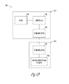
- FIG. 2B is a schematic illustration of the system shown in FIG. 2A .
- FIG. 3A is an illustration of a modular antitachyarrhythmia system that includes a sensing module, an analysis module, and a two therapy modules.
- FIG. 3B is a schematic illustration of the system shown in FIG. 3A .
- FIG. 4A is an illustration of a modular antitachyarrhythmia system that includes a sensing module and two antitachyarrhythmia therapy modules.
- FIG. 4B is a schematic illustration of the system shown in FIG. 4A .
- FIG. 5A is an illustration of a modular antitachyarrhythmia system that includes a therapy module and two sensing/analysis modules.
- FIG. 5B is a schematic illustration of the system shown in FIG. 5A .
- FIG. 6A is an illustration of a modular antitachyarrhythmia system that includes a sensing/therapy module and an analysis module.
- FIG. 6B is a schematic illustration of the system shown in FIG. 6A .
- FIG. 7A is an illustration of a modular antitachyarrhythmia system that includes a sensing module and an analysis/therapy module.
- FIG. 7B is a schematic illustration of the system shown in FIG. 7A .
- FIG. 8A is an illustration of a system that includes a plurality of sensing modules.
- FIG. 8B is a schematic illustration of the system shown in FIG. 8A .
- FIG. 9 is a schematic illustration of an embodiment of an antitachyarrhythmia therapy circuit.
- An antitachyarrhythmia system such as a defibrillation system, includes at least two physically separate modules that communicate with each other through a wireless communication. Numerous example systems are shown in FIGS. 1A to 8B .
- a module is a component that is used with other components, from which it is physically separate when implanted in the body. For example, in FIG. 1A , module 105 is used with module 110 and is physically separate from module 110 .
- wireless communication techniques include a radio frequency (RF) signal, inductive coupling, or conduction through the body.
- Wireless communications between modules include, for example, information about or derived from a physiologic parameter detected by a sensor, or one or more instructions to deliver, schedule, synchronize, or coordinate delivery of an antitachyarrhythmia therapy.
- wireless communication between modules avoids or reduces the use of leads.
- all of the modules are physically disjoint, i.e. there are not physical connections between them.
- FIGS. 1A-4A show examples of physically disjoint modules. In other examples, some of the modules are physically disjoint, and others are connected.
- the systems shown in FIGS. 5A and 6A include at least one leadless module and at least one module coupled to a lead.
- a modular antitachyarrhythmia system permits growth of a patient.
- a system implanted in a child can expand as a child grows, i.e. the modules can still operate as they become farther apart as the child grows because the modules are not tied together with leads.
- a modular antitachyarrhythmia system provides free range of motion to a patient.
- Modular antitachyarrhythmia systems can be used in one or more of a variety of applications.
- unique flux fields are created by strategically positioning modules containing electrodes.
- defibrillation vectors can be tailored by carefully positioning modules.
- FIG. 1A shows two separate defibrillation modules implanted near the heart.
- FIG. 2A shows two separate defibrillation modules implanted in the heart.
- leadless modules with electrodes are implantable in locations that would be practically impossible using tethered systems, such as certain portions of the peripheral vasculature.
- a module is sized and shaped for implantation in the pulmonary vasculature, such as in the pulmonary vasculature bed, or in the renal vasculature.
- one or more modules is implanted subcutaneously or submuscularly.
- a module is sized and shaped for implantation in the intraclavicle space inferior to the clavicle.
- a module is sized and shaped for implantation on or around the solar plexus.
- a module is sized and shaped for submuscular, intramuscular, intracardiac, or intravascular implantation.
- an intravascular or intracardiac module avoids occluding a blood vessel or interfering with valve heart valves.
- modules are implanted in locations that allow for near-field sensing of an intrinsic electrical heart signal.
- separate modules are positioned in or around specific locations of the heart or peripheral vasculature so that local intrinsic signals can be sensed at specific locations.
- a module is sized and shaped for implantation in a right ventricular apex.
- a module is sized and shaped for endocardial implantation, for example in a right atrium or right ventricle.
- a module is sized and shaped for implantation in a right atrial appendage.
- a module is sized and shaped for implantation in the coronary sinus, in vessels extending from the coronary sinus, or in other venous vasculature.
- a module is sized and shaped for implantation on an epicardial surface, such as on a left atrium or left ventricle epicardial surface.
- a module that is depleted or dysfunctional is replaced, while one or more other modules are left intact.
- a module implanted in the heart is left in place, while a module implanted outside the heart is replaced or upgraded.
- a subcutaneously implanted module for example, is replaceable with a relatively noninvasive procedure.
- a modular antitachyarrhythmia system can also be changed over time as needed by replacing or adding one or more modules.
- analysis or therapy programming circuits can be replaced or upgraded.
- pacing capability can be added by adding a pacing module. Modules can be added as a disease progresses or changes.
- a modular antitachyarrhythmia therapy system is implanted in a growing patient, such as a child.
- dissemination of the total volume of the modular system over more than one anatomic location enables local organ growth and overall body growth without compromising the functionality of the system.
- the reduction or elimination of leads enables organ growth or overall body growth, as the distance between components is allowed to change as the patient grows.
- the components of a system are implanted at predetermined anatomical locations in a patient.
- the components are then tested using a standardized protocol.
- the standardized protocol is integrated into an external programmer or other adjunct device.
- FIG. 1 is an example of a modular antitachyarrhythmia therapy system 100 .
- the antitachyarrhythmia system 100 includes two separate antitachyarrhythmia therapy modules 105 , 110 that cooperate to deliver a coordinated therapy.
- Module 105 includes two electrodes 106 , 107 and module 110 includes two electrodes 111 , 112 .
- the modules 105 , 106 each include a hermetically sealed electronics unit.
- the hermetically sealed electronics unit includes a housing and a header, and the electrodes 106 , 107 , 111 , 112 are located on the housing, on the header, or are contained in a lead that is coupled to a module header.
- module 105 delivers an antitachyarrhythmia therapy from electrode 106 through a portion of the heart 101 to electrode 107
- module 110 delivers an antitachyarrhythmia therapy from electrode 111 through a portion of the heart 101 to electrode 112 .
- the modules communicate with each other through wireless communication.
- the modules 105 , 110 coordinate or synchronize an antitachyarrhythmia therapy through the wireless communication.
- one or both of the modules 105 , 110 are implanted in the heart. In another example, one or both of the modules is implanted in the body but outside of the heart. In an example, at least one of the modules is sized and shaped for implantation in a peripheral cardiac vessel, such as the coronary sinus. In an example, a module includes a fixation helix that connects the module to heart tissue.
- a module is sized and shaped to be wedged into a vessel, such as in renal vasculature or pulmonary vasculature.
- a module is sized and shaped to be wedged into a vessel having a diameter that decreases in diameter along the length of the vessel, and wedging the module into the vessel fixes the module in place.
- the module occludes a portion of venous vasculature.
- a module is sized and shaped for implantation in coronary vasculature, such as in the coronary sinus.
- the module is driven in place using a lead.
- the modules 105 , 110 shown in FIG. 1A are both fully functional defibrillators, i.e. both modules includes sensing, analysis, and therapy circuitry.
- the modules operate in a master/slave relationship.
- module 105 operates as a master and includes analysis circuitry that directs delivery of an antitachyarrhythmia therapy through electrodes 111 , 112 , in module 110 .
- FIG. 1B shows a schematic illustration of one example of the system illustrated in FIG. 1A .
- module 105 includes sense circuit 115 , controller circuit 120 , antitachyarrhythmia therapy circuit 125 , and communication circuit 130 .
- the communication circuit 130 includes telemetry circuitry, such as an RF or inductive transceiver.
- the communication circuit uses a human or animal body as a conductive medium for a wireless communication.
- Sense circuit 115 detects one or more physiological parameters, such as cardiac performance data.
- sense circuit 115 includes a sense amplification circuit to detect at least one intrinsic electrical heart signal.
- Controller circuit 120 analyzes physiological data detected by the sense circuit 115 , determines whether a tachyarrhythmia is present, and determines at least one responsive antitachyarrhythmia therapy, such as a defibrillation shock therapy or antitachyarrhythmia pacing therapy.
- Antitachyarrhythmia therapy circuit 125 delivers the antitachyarrhythmia therapy determined by the controller circuit 120 .
- Antitachyarrhythmia circuit 125 includes the electrodes 106 , 107 shown in FIG. 1A .
- the antitachyarrhythmia circuit includes a pulse generator coupled to the electrodes, as shown in FIG. 9A .
- the pulse generator includes a battery, a capacitor, and circuitry for charging the capacitor and delivering a defibrillation therapy.
- module 110 is a second fully function defibrillator that includes a sense circuit 135 , a controller circuit 140 , an antitachyarrhythmia therapy circuit 145 , and a communication circuit 150 .
- Controller circuit 140 analyzes physiological data detected by the sense circuit 135 , determines whether a tachyarrhythmia is present, and determines at least one responsive antitachyarrhythmia therapy, which is delivered through the antitachyarrhythmia circuit 145 .
- the modules 105 , 110 communicate with each other through the communication circuits 130 , 150 , such as to coordinate, schedule, or synchronize therapy.
- one of the modules 105 , 110 also determines a therapy to be delivered through one of the modules 105 , 110 .
- module 110 operates as a slave module.
- module 110 does not include an analysis circuit.
- controller circuit 120 of module 105 determines a therapy based upon data received from sense circuit 135 and directs the antitachyarrhythmia therapy circuit 145 in the other module 110 to deliver a responsive therapy.
- module 110 includes neither a sense circuit nor an analysis circuit, and a therapy is determined from data provided by sense circuit 115 in module 105 .
- module 110 includes an analysis circuit, but module 105 determines an appropriate antitachyarrhythmia therapy and directs delivery of the therapy through module 110 .
- a pacing circuit is also provided in one or both of the antitachyarrhythmia modules.
- a physically separate pacing module including pacing circuitry and communication circuitry is provided, with the separate pacing module configured for communication with one or both of the modules 105 , 110 .
- a therapy for a patient is tailored by strategically positioning the antitachyarrhythmia modules 105 , 110 in anatomical locations to obtained desired vectors.
- the modules are implanted outside the heart, as shown in FIG. 1A .
- one or both modules are implanted in the heart.
- the modules 105 , 110 are implantable in a location that can be difficult to reach with an electrode tethered to a lead.
- one of the modules 105 , 110 is implanted in or on the left side of the heart 101 .
- a module is sized and shaped for implantation in the coronary sinus, in a vessel extending from the coronary sinus, or on an epicardial or pericardial surface.
- a module is affixed using a T-bar and a modified suture technique.
- the T-bar has an opening through which a needle is inserted.
- the left side of the heart is relatively difficult to reach with an endocardial defibrillation lead because of the complex vasculature through which such a lead would be inserted to reach the left side of the heart.
- implantation of a module avoids occlusion of a blood vessel or interference with a heart valve.
- the example antitachyarrhythmia system 200 includes three separate modules 205 , 210 , 215 that respectively perform therapy, sensing, and analysis.
- Sensing module 210 includes a sensor that detects at least one physiologic parameter, such as an intrinsic electrical heart signal or blood pressure.
- sensing module 210 is implanted on or around the heart.
- Analysis module 215 wirelessly receives information from sensing module 210 and processes the information to determine whether a tachyarrhythmia is present and determine an appropriate antitachyarrhythmia therapy.
- Analysis module 215 directs therapy module 205 to deliver an antitachyarrhythmia therapy through electrodes 206 , 207 .
- therapy module 205 delivers an antitachyarrhythmia therapy from electrode 206 through a portion of the heart 201 to electrode 207 .
- FIG. 2B shows a schematic illustration of the system illustrated in FIG. 2A .
- sensing module 210 includes sensor circuit 230 , which detects one or more physiological parameters, such as an intrinsic electrical heart signal.
- Sensing module 210 also includes a communication circuit 235 that wirelessly sends information about the one or more sensed parameters to the analysis module 215 .
- the communication circuit 235 includes telemetry circuitry, such as an inductive or RF transmitter or transceiver.
- Analysis module 215 includes controller circuit 240 and a communication circuit 245 that receives information sent by the communication circuit 235 in the sensing module 210 .
- Controller circuit 240 analyzes physiological data provided by the sensing module 210 and determines whether an antitachyarrhythmia is present and, if so, determines an appropriate antitachyarrhythmia therapy, such as a defibrillation shock therapy or antitachyarrhythmia pacing (ATP) therapy.
- the communication circuit 245 also includes a wireless transmitter, through which a direction is sent to the antitachyarrhythmia therapy module 205 to deliver the antitachyarrhythmia therapy.
- Antitachyarrhythmia therapy module 205 includes a communication circuit 225 including a wireless receiver that receives the communication from the communication circuit 245 in the analysis module 215 .
- Antitachyarrhythmia therapy module 205 also includes an antitachyarrhythmia therapy circuit 220 , which includes or is coupled to the electrodes 206 , 207 shown in FIG. 2A .
- the antitachyarrhythmia therapy circuit 220 delivers the antitachyarrhythmia therapy determined by the controller circuit 240 through the electrodes 206 , 207 .
- a pacing circuit is also provided in the antitachyarrhythmia module 205 , the sensing module 210 , or the analysis module 215 .
- the system includes a separate pacing module including pacing circuitry and communication circuitry.
- a therapy for a patient is obtained by strategically positioning the antitachyarrhythmia therapy module 205 in a particular anatomical location.
- the antitachyarrhythmia therapy module 205 is implanted in the heart, as shown in FIG. 2A .
- the antitachyarrhythmia therapy module 205 is implanted in the right ventricle.
- the module 205 is implantable in or on the left side of the heart.
- the sensing module 210 is also placed in a desired location for sensing one or more parameters, such as an intrinsic electrical heart signal.
- the analysis module 215 is implanted subcutaneously, which allows the analysis module 215 to be replaced or upgraded without requiring replacement of other separate modules that are implanted deeper in the body.
- the analysis module 215 is implanted near the abdomen, as shown in FIG. 2A .
- the analysis module 215 is implanted subcutaneously, such as on the left side of the upper body near the heart.
- the example antitachyarrhythmia system 300 includes a sensing module 320 , a separate analysis module 315 , and two separate antitachyarrhythmia therapy modules 305 , 310 that deliver a coordinated antitachyarrhythmia therapy.
- Sensing module 320 includes a sensor that detects a physiologic parameter, such as an intrinsic electrical heart signal or blood pressure.
- Analysis module 315 receives information from sensing module 320 and processes the information to determine an antitachyarrhythmia therapy.
- Analysis module 315 directs therapy modules 305 , 310 to deliver a coordinated antitachyarrhythmia therapy through electrodes 306 , 307 , 311 , 312 .
- therapy module 305 delivers an antitachyarrhythmia therapy from electrode 306 through a portion of the heart 301 to electrode 307
- therapy module 310 delivers an antitachyarrhythmia therapy from electrode 311 through a portion of the heart 301 to electrode 312 .
- FIG. 3B shows a schematic illustration of the system illustrated in FIG. 3A .
- Sensing module 320 includes sensor circuit 355 , which detects one or more physiological parameters, such as an intrinsic electrical heart signal.
- Sensing module 320 also includes a communication circuit 360 that sends information about the one or more sensed parameters to the analysis module 315 .
- the communication circuit 360 in the sensing module 320 includes telemetry circuitry, such as an inductive or RF transmitter.
- the communication circuit 360 includes an inductive or RF transceiver.
- Analysis module 315 includes controller circuit 345 and communication circuit 350 . The communication circuit 350 in the analysis module 315 receives information sent by the communication circuit 360 in the sensing module 320 .
- Controller circuit 345 analyzes physiological data provided by the sensing module 320 and determines an antitachyarrhythmia therapy, such as a defibrillation shock therapy.
- Antitachyarrhythmia therapy modules 305 , 310 include respective communication circuits 330 , 340 that receive a communication from the communication circuit 350 in the analysis module 315 .
- Antitachyarrhythmia therapy modules 305 , 310 also include respective antitachyarrhythmia circuits 325 , 335 , which respectively include the electrodes 306 , 307 , 311 , 312 shown in FIG. 3A .
- Antitachyarrhythmia therapy modules 305 , 310 deliver the antitachyarrhythmia therapy determined by the controller circuit 345 through the electrodes 306 , 307 , 311 , 312 .
- the analysis module coordinates delivery of a therapy by the antitachyarrhythmia modules 305 , 310 .
- the communication circuits 330 , 340 in the antitachyarrhythmia modules 305 , 310 communicate with each other to coordinate or synchronize an antitachyarrhythmia therapy.
- the analysis module 315 is implanted subcutaneously and can be replaced or upgraded with a relatively minor procedure without altering or disturbing the other modules in the system.
- antitachyarrhythmia therapy module 305 is implanted in the heart and antitachyarrhythmia therapy module 310 is implanted outside the heart.
- antitachyarrhythmia therapy module 305 is implanted in the left side of the heart and antitachyarrhythmia therapy module 310 is implanted in the right side of the heart.
- sensing module 320 or other modules are in or on the heart, or in an epicardial space.
- sensing module 320 is implanted in the right side of the heart.
- the example antitachyarrhythmia system 400 includes a sensing module 415 and two separate antitachyarrhythmia therapy modules 405 , 410 .
- Sensing module 415 includes a sensor that detects a physiologic parameter, such as an intrinsic electrical heart signal or blood pressure.
- Therapy module 405 includes two electrodes 406 , 407 and therapy module 410 includes two electrodes 411 , 412 .
- therapy module 405 delivers an antitachyarrhythmia therapy from electrode 406 through a portion of the heart 401 to electrode 407
- therapy module 410 delivers an antitachyarrhythmia therapy from electrode 411 through a portion of the heart 401 to electrode 412
- the modules 405 , 410 , 415 communicate wirelessly.
- the therapy modules 405 , 410 coordinate or synchronize a therapy through the wireless communication.
- FIG. 4B shows a schematic illustration of the system illustrated in FIG. 4A .
- Sensing module 415 includes sense circuit 450 , which detects one or more physiological parameters, such as an intrinsic electrical heart signal.
- Sensing module 415 also includes a communication circuit 455 that sends information about the one or more sensed parameters to the other modules.
- the communication circuit 455 includes an inductive or RF transmitter.
- the communication circuit 455 includes an inductive or RF transceiver.
- Modules 405 , 410 include respective controller circuits 420 , 435 , antitachyarrhythmia therapy circuits 425 , 440 and communication circuits 430 , 445 .
- the communication circuits 430 , 445 receive information from the communication circuit 455 in the sensing module 415 .
- Controller circuits 420 , 435 analyze physiological data provided by the sense circuit 450 and determine an antitachyarrhythmia therapy, such as a defibrillation shock therapy.
- Antitachyarrhythmia therapy circuits 425 , 440 include the respective electrodes 406 , 407 and 410 , 411 .
- Antitachyarrhythmia therapy circuits 425 , 440 deliver an antitachyarrhythmia therapy determined by the respective controller circuit 420 , 435 through the respective electrodes 406 , 407 and 410 , 411 .
- antitachyarrhythmia modules 405 , 410 communicate to coordinate or synchronize delivery of an antitachyarrhythmia therapy.
- separate modules 405 , 410 , 415 are implanted outside the heart. In another example, one or more of the separate modules 405 , 410 , 415 are implanted in the heart.
- the example system 500 includes a therapy module 505 and a separate sensing/analysis module 510 that performs sensing and analysis.
- Sensing/analysis module 510 includes a sensor 515 that detects a physiologic parameter and also includes controller circuitry that receives information from the sensor 515 and processes the information to determine whether a tachyarrhythmia is present and, if so, determines an appropriate antitachyarrhythmia therapy.
- the controller circuitry is contained in a housing 514 and the sensor 515 is connected to the housing with a lead 516 .
- Analysis module 510 directs therapy module 505 to deliver an antitachyarrhythmia therapy through electrodes 506 , 507 .
- therapy module 505 delivers an antitachyarrhythmia therapy from electrode 506 through a portion of the heart 501 to electrode 507 .
- antitachyarrhythmia therapy module 505 is implanted outside the heart as shown in FIG. 5A , such as in the subcutaneously below or between the ribs.
- antitachyarrhythmia module 505 is implanted in the heart, such as in the right atrium or right ventricle.
- FIG. 5B shows a schematic illustration of the system illustrated in FIG. 5A .
- Sensing/analysis module 510 includes controller circuit 530 , sensor circuit 540 , and communication circuit 535 .
- Sensor circuit 540 includes the sensor 515 that detects one or more physiological parameters.
- Controller circuit 530 analyzes physiological data provided by the sensor circuit 540 and determines whether a tachyarrhythmia is present and, if so, determines an appropriate antitachyarrhythmia therapy, such as a defibrillation shock therapy or antitachyarrhythmia pacing (ATP) therapy.
- ATP antitachyarrhythmia pacing
- a direction such as a direction to initiate or adjust the antitachyarrhythmia therapy, is sent to the antitachyarrhythmia therapy module 505 through the communication circuit 535 .
- the communication circuit 535 includes telemetry circuitry, such as an inductive or RF transmitter.
- the communication circuit 535 includes an inductive or RF transceiver.
- Antitachyarrhythmia therapy module 505 includes a communication circuit 525 that receives the communication from the communication circuit 535 in the analysis module 510 .
- Antitachyarrhythmia therapy module 505 also includes an antitachyarrhythmia therapy circuit 520 , which includes the electrodes 506 , 507 shown in FIG. 5A .
- Antitachyarrhythmia therapy circuit 520 delivers the antitachyarrhythmia therapy determined by the controller circuit 530 through the electrodes 506 , 507 .
- the example system 600 includes a sensing/therapy module 605 and a separate analysis module 615 .
- Sensing/therapy module 605 includes a sensor 610 that detects a physiologic parameter and also includes therapy circuitry that delivers an antitachyarrhythmia therapy.
- sensor 610 is located in the heart.
- sensor 610 is located outside the heart.
- the therapy circuitry is contained in a housing 614 and the sensor 610 is connected to the housing with a lead 616 .
- the sensing/therapy module 605 communicates wirelessly with an analysis module 615 .
- Analysis module determines whether a tachyarrhythmia is present and, if so, directs sensing/therapy module 605 to deliver an appropriate antitachyarrhythmia therapy through electrodes 606 , 607 .
- therapy module 605 delivers an antitachyarrhythmia therapy from electrode 606 through a portion of the heart 601 to electrode 607 .
- the sensing/therapy module 605 is implanted outside the heart, as shown in FIG. 6A . In another example, the sensing/therapy module is implanted in the heart.
- FIG. 6B shows a schematic illustration of the system illustrated in FIG. 6A .
- Sensing/therapy module 605 includes sense circuit 625 , antitachyarrhythmia therapy circuit 620 , and communication circuit 630 .
- the antitachyarrhythmia therapy circuit 620 includes the electrodes 606 , 607 shown in FIG. 6A .
- Sense circuit 625 includes the sensor 610 that detects one or more physiological parameters.
- Sensing/therapy module 605 sends physiological data through communication circuit 630 to the analysis module.
- Analysis module 615 includes a controller circuit 635 and a communication circuit 640 .
- Communication circuit 640 receives the communication from the sensing/analysis module 605 .
- the communication circuits 630 , 640 each include an RF transceiver and the circuits communicate through RF signals.
- Controller circuit 635 analyzes physiological data provided by the sense circuit 640 and determines an antitachyarrhythmia therapy, such as a defibrillation shock therapy or ATP therapy. Analysis module then sends an antitachyarrhythmia therapy instruction through the communication circuit 640 to the antitachyarrhythmia therapy module 605 .
- Antitachyarrhythmia therapy circuit 620 delivers the antitachyarrhythmia therapy determined by the controller circuit 635 through the electrodes 606 , 607 .
- the example system 700 includes a sensing module 710 and an analysis/therapy module 705 .
- Sensing module 710 includes a sensor 711 that detects a physiologic parameter.
- the sensing module 710 communicates wirelessly with an analysis/therapy module 715 .
- Analysis/therapy module 705 includes controller circuitry that analyzes data provided by the sensing module 710 and determines whether a tachyarrhythmia is present and, if so, determines an appropriate antitachyarrhythmia therapy.
- Analysis/therapy module 705 also includes therapy circuitry that delivers the antitachyarrhythmia therapy, for example, to a heart 701 .
- FIG. 7B shows a schematic illustration of the system illustrated in FIG. 7A .
- Sensing module 710 includes a sense circuit 730 that includes the sensor 711 shown in FIG. 7A .
- Sensing module 710 also includes a communication circuit 735 that sends information about sensed physiologic parameters to the analysis/therapy module 705 .
- Analysis/therapy module 705 includes controller circuit 720 , antitachyarrhythmia therapy circuit 715 , and communication circuit 725 .
- Communication circuit 725 receives the communication from the sensing module 710 .
- the communication circuits 725 , 735 each include telemetry circuitry, and the circuits communicate through RF or inductive signals.
- Controller circuit 720 analyzes physiological data provided by the sense circuit 730 and determines whether a tachyarrhythmia is present and, if so, determines an appropriate antitachyarrhythmia therapy, such as a defibrillation shock therapy or ATP therapy. The controller circuit 720 then sends an antitachyarrhythmia therapy delivery instruction to the antitachyarrhythmia therapy circuit 715 .
- Antitachyarrhythmia therapy circuit 715 delivers the antitachyarrhythmia therapy determined by the controller circuit 720 .
- the antitachyarrhythmia therapy circuit includes electrodes that are integrated into a housing of the analysis/therapy module that carries its electronics.
- one of the systems shown in FIGS. 1A-7A includes one or more additional modules.
- a system includes a memory module including a memory circuit and communication circuit.
- a system includes a pacing module including pacing circuitry.
- a system includes a respiratory sensing module including respiratory sensing circuitry.
- a system includes a respiratory stimulation module including respiratory stimulation circuitry.
- a system includes a chemical sensor module or a chemical or drug delivery module.
- a system includes sensors that detect blood chemistry in the heart or in arteries or other vessels.
- a system includes one or more sensors detect oxygen saturation and/or pH levels in blood.
- certain modules are combined into a system that includes at least two separately located modules that wirelessly communicate with each other.
- pacing circuitry is included in a defibrillation module or a heart sensing module.
- respiration sensing and respiration stimulation are performed by a single module.
- chemical sensors or chemical delivery mechanisms are included with antitachyarrhythmia therapy modules or other modules.
- FIG. 8A shows an example of a modular implantable system 800 that includes a variety of separate sensor modules.
- FIG. 8B is a schematic illustration of the system shown in FIG. 8A that shows schematic illustrations of circuits in the modules.
- the system 800 includes separate modules 802 , 804 , 806 , 812 , 814 , 816 .
- each of the separate modules 802 , 804 , 806 , 812 , 814 , 816 includes a sensor to sense a physiologic parameter and a wireless transmitter circuit to send a wireless communication that includes information about the physiologic parameter.
- two or more of the sense circuits are coupled to another module with a lead or are combined in a single module.
- module 802 includes a sense amplification circuit 842 (shown in FIG. 8B ) to detect an intrinsic electrical heart signal and a wireless transmitter circuit 843 that transmits information about the intrinsic electrical heart signal.
- module 804 includes a heart sound sensor 844 to detect a heart sound and a wireless transmitter circuit 845 that transmits information about the heart sound.
- module 806 includes a respiration sensor 846 and a wireless transmitter circuit 847 that transmits information about the respiration.
- module 808 includes a wireless receiver circuit 849 to receive a diaphragmatic pacing instruction and a diaphragm stimulation circuit 848 to deliver a diaphragmatic pacing pulse.
- module 806 and 808 are combined in a single module.
- module 810 includes a pacing stimulation circuit 850 to deliver a pacing pulse and a wireless receiver circuit 851 that receive a pacing instruction.
- module 812 includes a blood pressure sensor 852 to detect blood pressure and a wireless transmitter circuit 853 that transmits information about the blood pressure.
- module 812 is sized and shaped for implantation in the heart, or in vasculature near the heart.
- module 812 is sized and shaped for implantation in pulmonary vasculature, such as in the pulmonary vascular bed.
- the pacing stimulation circuit in module 810 adjusts delivery of a pacing pulse in response to information provided from another module, such as information about the blood pressure provided by module 812 .
- module 814 includes an atrial sensing circuit 854 that senses an intrinsic electrical atrial signal and a wireless communication circuit 855 that transmits includes information about the atrial signal.
- module 816 includes a ventricular sensing circuit 856 that senses an intrinsic electrical ventricular signal, and a wireless transmitter 857 that transmits information about the ventricular signal.
- one or more of modules 802 , 804 , 806 , 812 , 814 , 816 include circuitry that processes a signal or data obtained from a physiological sensor.
- module 820 includes a wireless receiver or transceiver circuit 821 that receives a wireless communication from one or more of the other modules.
- Module 820 also includes a controller circuit 822 that uses the information about one or more physiologic parameters received from one or more of the other modules 802 , 804 , 806 , 812 , 814 , 816 , such as to provide diagnostic information or to determine therapy.
- the controller circuit 822 uses information about the atrial signal received from module 814 .
- the controller circuit 822 uses information about the ventricular signal received from module 816 .
- the controller circuit 822 uses information about both the atrial and ventricular signals.
- module 820 also includes an antitachyarrhythmia therapy circuit that delivers a responsive antitachyarrhythmia therapy.
- module 820 includes a wireless transmitter circuit 821 that transmits a wireless antitachyarrhythmia therapy instruction to module 830 , which includes a communication circuit 834 and antitachyarrhythmia circuitry 832 that delivers an antitachyarrhythmia therapy in accordance with the instruction from module 820 .
- modules 820 and 830 each include an antitachyarrhythmia therapy circuit.
- module 820 is implanted subcutaneously and can be replaced without replacing other modules.
- modules 802 , 804 , 806 , 808 , 810 , 812 , 814 , 816 , 820 , 830 are combined together in a system that includes at least two separate modules that wirelessly communicate with each other.
- the modules 802 , 804 , 812 that respectively sense blood pressure, heart sound, and an intrinsic electrical heart signal are combined into a single module 803 that includes such sensors and a wireless transmitter that transmits information about various physiological parameters detected by the sensors.
- the system receives information about physiologic parameters through multiple channels.
- the system 800 is senses at least two physiologic parameters concurrently using physically separate modules, and includes a memory circuit that records information relating to the at least two physiologic parameters.
- the system includes stores information about physiologic parameters received before a tachyarrhythmia in the memory circuit.
- the system includes an implantable memory circuit that can be replaced without replacing other modules.
- FIG. 9 is a schematic illustration of an example of an antitachyarrhythmia therapy circuit 900 .
- a pulse generator 905 includes a battery 910 and a pulse circuit 906 .
- the pulse circuit 906 includes a capacitor for building a charge that is deliverable in a pulse across the electrodes.
- the pulse generator 905 receives an instruction from a controller circuit 925 .
- the controller circuit 925 communicates through telemetry circuitry coupled to the pulse generator 905 .
- the controller circuit 925 is physically connected to the pulse generator 905 .
- the controller circuit 925 instructs the pulse generator 905 to draws power from the battery and delivers an energy, such as a defibrillation shock, across electrodes 915 , 920 .
Abstract
This document discusses, among other things, a modular antitachyarrhythmia therapy system. In an example, a modular antitachyarrhythmia system includes at least two separate modules that coordinate delivery an antitachyarrhythmia therapy, such as defibrillation therapy. In another example, a modular antitachyarrhythmia therapy system includes a sensing module, an analysis module, and a therapy module.
Description
This application is a divisional of Smith, et al., U.S. patent application Ser. No. 14/164,447, entitled “MODULAR ANTITACHYARRHYTHMIA THERAPY SYSTEM,” filed on Jan. 27, 2014; which is a continuation of and claims the benefit of priority under 35 U.S.C. §120 to Smith et al., U.S. patent application Ser. No. 13/662,882, entitled “MODULAR ANTITACHYARRHYTHMIA THERAPY SYSTEM,” filed on Oct. 29, 2012, now U.S. Pat. No. 8,649,859; which is a continuation of Smith et al., U.S. patent application Ser. No. 11/131,583, entitled “MODULAR ANTITACHYARRHYTHMIA THERAPY SYSTEM,” filed on May 18, 2005, now U.S. Pat. No. 8,391,990; each of which are hereby incorporated by reference herein in its entirety.
This patent document pertains generally to arrhythmia therapy devices and methods, and more particularly, but not by way of limitation, to modular implantable devices that are configured to deliver an antitachyarrhythmia therapy.
Implantable arrhythmia therapy devices such as pacers and defibrillators typically include a power source such as a battery, an electrode, and a controller. A lead carrying the electrode typically has a proximal end that is coupled to a housing that contains the power source and controller, and a distal end that is located in, on, or around the heart. A lead can be introduced into a heart chamber, for example.
A pacing lead typically includes at least one electrode that is configured to deliver a pacing pulse, and a conductor that couples the electrode to a signal generator. Some pacing leads also include a sensing electrode and a second conductor that couples the sensing electrode to a sensing circuit.
A defibrillation lead typically includes an anode and a cathode. For example, a typical defibrillation lead includes two coils that are coupled to anode and cathode portions of a battery. A vector is defined between the anode and cathode. The effectiveness of a defibrillation therapy is affected by the configuration of the anode and cathode, and the vector defined by the anode and cathode.
In some patients, the presence of one or more implanted leads restricts on the patient's range of motion. Moreover, in a growing patient, such as a child, the patient may outgrow a lead. In some growing patients, it can be necessary to periodically explant a pacer or defibrillator and replace the device or implant longer or different leads.
Improved implantable arrhythmia therapy devices are needed.
In an example, a modular implantable device or system includes an implantable first and an implantable second circuit physically separate from the first circuit. The implantable first circuit includes a sensor to sense a physiologic parameter and a wireless transmitter circuit to send a wireless communication that includes information derived from the physiologic parameter. The implantable second circuit includes a wireless receiver circuit to receive the wireless communication and an antitachyarrhythmia therapy circuit to deliver a responsive antitachyarrhythmia therapy.
In another example, a modular implantable device or system includes an implantable first circuit, an implantable second circuit, physically separate from the first circuit, and an implantable third circuit, physically separate from the second circuit. The implantable first circuit includes a sensor to sense a physiologic parameter, and a communication or driver circuit to send a communication that includes information about the physiologic parameter. The implantable second circuit includes a receiver circuit to receive the communication from the first implantable circuit, a controller circuit to analyze the information about the physiologic parameter, and a wireless transmitter circuit to send a wireless therapy instruction. The implantable third circuit includes a wireless receiver to receive the wireless therapy instruction, and an antitachyarrhythmia therapy circuit to deliver an antitachyarrhythmia therapy.
In another example, a modular implantable device includes an implantable first defibrillation circuit module configured to deliver a first defibrillation shock, an implantable second defibrillation circuit module, physically separate from the first defibrillation circuit module, configured to deliver a second defibrillation shock concurrent with the first defibrillation shock, and a controller circuit configured to direct coordinated delivery of the first and second defibrillation shocks.
In the drawings, which are not necessarily drawn to scale, like numerals describe substantially similar components throughout the several views. The drawings illustrate generally, by way of example, but not by way of limitation, various embodiments discussed in the present document.
An antitachyarrhythmia system, such as a defibrillation system, includes at least two physically separate modules that communicate with each other through a wireless communication. Numerous example systems are shown in FIGS. 1A to 8B . A module is a component that is used with other components, from which it is physically separate when implanted in the body. For example, in FIG. 1A , module 105 is used with module 110 and is physically separate from module 110.
Examples of wireless communication techniques include a radio frequency (RF) signal, inductive coupling, or conduction through the body. Wireless communications between modules include, for example, information about or derived from a physiologic parameter detected by a sensor, or one or more instructions to deliver, schedule, synchronize, or coordinate delivery of an antitachyarrhythmia therapy. In one example, wireless communication between modules avoids or reduces the use of leads. In some examples, all of the modules are physically disjoint, i.e. there are not physical connections between them. FIGS. 1A-4A show examples of physically disjoint modules. In other examples, some of the modules are physically disjoint, and others are connected. For example, the systems shown in FIGS. 5A and 6A include at least one leadless module and at least one module coupled to a lead.
In an example, a modular antitachyarrhythmia system permits growth of a patient. For example, a system implanted in a child can expand as a child grows, i.e. the modules can still operate as they become farther apart as the child grows because the modules are not tied together with leads. In another example, a modular antitachyarrhythmia system provides free range of motion to a patient.
Modular antitachyarrhythmia systems, such as the systems shown in FIGS. 1A-8B , can be used in one or more of a variety of applications. In one example, unique flux fields are created by strategically positioning modules containing electrodes. For example, defibrillation vectors can be tailored by carefully positioning modules. The example illustrated in FIG. 1A shows two separate defibrillation modules implanted near the heart. FIG. 2A shows two separate defibrillation modules implanted in the heart. In some examples, leadless modules with electrodes are implantable in locations that would be practically impossible using tethered systems, such as certain portions of the peripheral vasculature. In an example, a module is sized and shaped for implantation in the pulmonary vasculature, such as in the pulmonary vasculature bed, or in the renal vasculature. In an example, one or more modules is implanted subcutaneously or submuscularly. In an example, a module is sized and shaped for implantation in the intraclavicle space inferior to the clavicle. In another example, a module is sized and shaped for implantation on or around the solar plexus. In another example, a module is sized and shaped for submuscular, intramuscular, intracardiac, or intravascular implantation. In an example, an intravascular or intracardiac module avoids occluding a blood vessel or interfering with valve heart valves.
In an example, modules are implanted in locations that allow for near-field sensing of an intrinsic electrical heart signal. In one example, separate modules are positioned in or around specific locations of the heart or peripheral vasculature so that local intrinsic signals can be sensed at specific locations. In an example, a module is sized and shaped for implantation in a right ventricular apex. In an example, a module is sized and shaped for endocardial implantation, for example in a right atrium or right ventricle. In an example, a module is sized and shaped for implantation in a right atrial appendage. In an example, a module is sized and shaped for implantation in the coronary sinus, in vessels extending from the coronary sinus, or in other venous vasculature. In an example, a module is sized and shaped for implantation on an epicardial surface, such as on a left atrium or left ventricle epicardial surface.
In other examples, a module that is depleted or dysfunctional is replaced, while one or more other modules are left intact. In one example, a module implanted in the heart is left in place, while a module implanted outside the heart is replaced or upgraded. A subcutaneously implanted module, for example, is replaceable with a relatively noninvasive procedure.
Some examples of a modular antitachyarrhythmia system can also be changed over time as needed by replacing or adding one or more modules. For example, analysis or therapy programming circuits can be replaced or upgraded. In another example, pacing capability can be added by adding a pacing module. Modules can be added as a disease progresses or changes.
In another example, a modular antitachyarrhythmia therapy system is implanted in a growing patient, such as a child. In an example, dissemination of the total volume of the modular system over more than one anatomic location enables local organ growth and overall body growth without compromising the functionality of the system. In an example, the reduction or elimination of leads enables organ growth or overall body growth, as the distance between components is allowed to change as the patient grows.
In an example implant method, the components of a system are implanted at predetermined anatomical locations in a patient. In an example, the components are then tested using a standardized protocol. In an example, the standardized protocol is integrated into an external programmer or other adjunct device.
Examples of Modular Antitachyarrhythmia Systems
In an example, one or both of the modules 105, 110 are implanted in the heart. In another example, one or both of the modules is implanted in the body but outside of the heart. In an example, at least one of the modules is sized and shaped for implantation in a peripheral cardiac vessel, such as the coronary sinus. In an example, a module includes a fixation helix that connects the module to heart tissue.
In an example, a module is sized and shaped to be wedged into a vessel, such as in renal vasculature or pulmonary vasculature. In an example, a module is sized and shaped to be wedged into a vessel having a diameter that decreases in diameter along the length of the vessel, and wedging the module into the vessel fixes the module in place. In an example, the module occludes a portion of venous vasculature.
In another example, a module is sized and shaped for implantation in coronary vasculature, such as in the coronary sinus. In an example, the module is driven in place using a lead.
In an example, the modules 105, 110 shown in FIG. 1A are both fully functional defibrillators, i.e. both modules includes sensing, analysis, and therapy circuitry. In another example, the modules operate in a master/slave relationship. In one example, module 105 operates as a master and includes analysis circuitry that directs delivery of an antitachyarrhythmia therapy through electrodes 111, 112, in module 110.
In an example, module 110 is a second fully function defibrillator that includes a sense circuit 135, a controller circuit 140, an antitachyarrhythmia therapy circuit 145, and a communication circuit 150. Controller circuit 140 analyzes physiological data detected by the sense circuit 135, determines whether a tachyarrhythmia is present, and determines at least one responsive antitachyarrhythmia therapy, which is delivered through the antitachyarrhythmia circuit 145. The modules 105, 110 communicate with each other through the communication circuits 130, 150, such as to coordinate, schedule, or synchronize therapy.
In an example master/slave system, one of the modules 105, 110 also determines a therapy to be delivered through one of the modules 105, 110. In an example, module 110 operates as a slave module. In one example, module 110 does not include an analysis circuit. In this example, controller circuit 120 of module 105 determines a therapy based upon data received from sense circuit 135 and directs the antitachyarrhythmia therapy circuit 145 in the other module 110 to deliver a responsive therapy. In another example, module 110 includes neither a sense circuit nor an analysis circuit, and a therapy is determined from data provided by sense circuit 115 in module 105. In another example, module 110 includes an analysis circuit, but module 105 determines an appropriate antitachyarrhythmia therapy and directs delivery of the therapy through module 110.
In an example, a pacing circuit is also provided in one or both of the antitachyarrhythmia modules. In another example, a physically separate pacing module including pacing circuitry and communication circuitry is provided, with the separate pacing module configured for communication with one or both of the modules 105, 110.
In an example, a therapy for a patient is tailored by strategically positioning the antitachyarrhythmia modules 105, 110 in anatomical locations to obtained desired vectors. In an example, the modules are implanted outside the heart, as shown in FIG. 1A . Alternatively, one or both modules are implanted in the heart. In an example, the modules 105, 110 are implantable in a location that can be difficult to reach with an electrode tethered to a lead. In an example, one of the modules 105, 110 is implanted in or on the left side of the heart 101. In an example, a module is sized and shaped for implantation in the coronary sinus, in a vessel extending from the coronary sinus, or on an epicardial or pericardial surface. In an example, a module is affixed using a T-bar and a modified suture technique. In an example, the T-bar has an opening through which a needle is inserted.
The left side of the heart is relatively difficult to reach with an endocardial defibrillation lead because of the complex vasculature through which such a lead would be inserted to reach the left side of the heart. In an example, implantation of a module avoids occlusion of a blood vessel or interference with a heart valve.
Another example of a modular antitachyarrhythmia therapy system is shown in FIG. 2A . The example antitachyarrhythmia system 200 includes three separate modules 205, 210, 215 that respectively perform therapy, sensing, and analysis. Sensing module 210 includes a sensor that detects at least one physiologic parameter, such as an intrinsic electrical heart signal or blood pressure. In another example, sensing module 210 is implanted on or around the heart. Analysis module 215 wirelessly receives information from sensing module 210 and processes the information to determine whether a tachyarrhythmia is present and determine an appropriate antitachyarrhythmia therapy. Analysis module 215 directs therapy module 205 to deliver an antitachyarrhythmia therapy through electrodes 206, 207. In an example, therapy module 205 delivers an antitachyarrhythmia therapy from electrode 206 through a portion of the heart 201 to electrode 207.
In an example, a pacing circuit is also provided in the antitachyarrhythmia module 205, the sensing module 210, or the analysis module 215. In another example, the system includes a separate pacing module including pacing circuitry and communication circuitry.
In an example, a therapy for a patient is obtained by strategically positioning the antitachyarrhythmia therapy module 205 in a particular anatomical location. In an example, the antitachyarrhythmia therapy module 205 is implanted in the heart, as shown in FIG. 2A . In an example, the antitachyarrhythmia therapy module 205 is implanted in the right ventricle. In another example, the module 205 is implantable in or on the left side of the heart. In an example, the sensing module 210 is also placed in a desired location for sensing one or more parameters, such as an intrinsic electrical heart signal. In an example, the analysis module 215 is implanted subcutaneously, which allows the analysis module 215 to be replaced or upgraded without requiring replacement of other separate modules that are implanted deeper in the body. In another example, the analysis module 215 is implanted near the abdomen, as shown in FIG. 2A . Alternatively, the analysis module 215 is implanted subcutaneously, such as on the left side of the upper body near the heart.
Another example of a modular antitachyarrhythmia therapy system 300 is shown in FIG. 3A . The example antitachyarrhythmia system 300 includes a sensing module 320, a separate analysis module 315, and two separate antitachyarrhythmia therapy modules 305, 310 that deliver a coordinated antitachyarrhythmia therapy. Sensing module 320 includes a sensor that detects a physiologic parameter, such as an intrinsic electrical heart signal or blood pressure. Analysis module 315 receives information from sensing module 320 and processes the information to determine an antitachyarrhythmia therapy. Analysis module 315 directs therapy modules 305, 310 to deliver a coordinated antitachyarrhythmia therapy through electrodes 306, 307, 311, 312. In an example, therapy module 305 delivers an antitachyarrhythmia therapy from electrode 306 through a portion of the heart 301 to electrode 307, and therapy module 310 delivers an antitachyarrhythmia therapy from electrode 311 through a portion of the heart 301 to electrode 312.
In an example, the analysis module 315 is implanted subcutaneously and can be replaced or upgraded with a relatively minor procedure without altering or disturbing the other modules in the system. In an example, antitachyarrhythmia therapy module 305 is implanted in the heart and antitachyarrhythmia therapy module 310 is implanted outside the heart. In another example, antitachyarrhythmia therapy module 305 is implanted in the left side of the heart and antitachyarrhythmia therapy module 310 is implanted in the right side of the heart. In an example, sensing module 320 or other modules are in or on the heart, or in an epicardial space. In an example, sensing module 320 is implanted in the right side of the heart.
Another example of a modular antitachyarrhythmia therapy system is shown in FIG. 4A . The example antitachyarrhythmia system 400 includes a sensing module 415 and two separate antitachyarrhythmia therapy modules 405, 410. Sensing module 415 includes a sensor that detects a physiologic parameter, such as an intrinsic electrical heart signal or blood pressure. Therapy module 405 includes two electrodes 406, 407 and therapy module 410 includes two electrodes 411, 412. In an example, therapy module 405 delivers an antitachyarrhythmia therapy from electrode 406 through a portion of the heart 401 to electrode 407, and therapy module 410 delivers an antitachyarrhythmia therapy from electrode 411 through a portion of the heart 401 to electrode 412. The modules 405, 410, 415 communicate wirelessly. In an example, the therapy modules 405, 410 coordinate or synchronize a therapy through the wireless communication.
In an example, separate modules 405, 410, 415 are implanted outside the heart. In another example, one or more of the separate modules 405, 410, 415 are implanted in the heart.
Another example of a modular antitachyarrhythmia therapy system is shown in FIG. 5A . The example system 500 includes a therapy module 505 and a separate sensing/analysis module 510 that performs sensing and analysis. Sensing/analysis module 510 includes a sensor 515 that detects a physiologic parameter and also includes controller circuitry that receives information from the sensor 515 and processes the information to determine whether a tachyarrhythmia is present and, if so, determines an appropriate antitachyarrhythmia therapy. In an example, the controller circuitry is contained in a housing 514 and the sensor 515 is connected to the housing with a lead 516. Analysis module 510 directs therapy module 505 to deliver an antitachyarrhythmia therapy through electrodes 506, 507. In an example, therapy module 505 delivers an antitachyarrhythmia therapy from electrode 506 through a portion of the heart 501 to electrode 507. In an example, antitachyarrhythmia therapy module 505 is implanted outside the heart as shown in FIG. 5A , such as in the subcutaneously below or between the ribs. In another example, antitachyarrhythmia module 505 is implanted in the heart, such as in the right atrium or right ventricle.
Another example of a modular antitachyarrhythmia therapy system is shown in FIG. 6A . The example system 600 includes a sensing/therapy module 605 and a separate analysis module 615. Sensing/therapy module 605 includes a sensor 610 that detects a physiologic parameter and also includes therapy circuitry that delivers an antitachyarrhythmia therapy. In an example, sensor 610 is located in the heart. In another example, sensor 610 is located outside the heart. In an example, the therapy circuitry is contained in a housing 614 and the sensor 610 is connected to the housing with a lead 616. The sensing/therapy module 605 communicates wirelessly with an analysis module 615. Analysis module determines whether a tachyarrhythmia is present and, if so, directs sensing/therapy module 605 to deliver an appropriate antitachyarrhythmia therapy through electrodes 606, 607. In an example, therapy module 605 delivers an antitachyarrhythmia therapy from electrode 606 through a portion of the heart 601 to electrode 607. In an example, the sensing/therapy module 605 is implanted outside the heart, as shown in FIG. 6A . In another example, the sensing/therapy module is implanted in the heart.
Another example of a modular antitachyarrhythmia therapy system is shown in FIG. 7A . The example system 700 includes a sensing module 710 and an analysis/therapy module 705. Sensing module 710 includes a sensor 711 that detects a physiologic parameter. The sensing module 710 communicates wirelessly with an analysis/therapy module 715. Analysis/therapy module 705 includes controller circuitry that analyzes data provided by the sensing module 710 and determines whether a tachyarrhythmia is present and, if so, determines an appropriate antitachyarrhythmia therapy. Analysis/therapy module 705 also includes therapy circuitry that delivers the antitachyarrhythmia therapy, for example, to a heart 701.
In other examples, one of the systems shown in FIGS. 1A-7A includes one or more additional modules. In one example, a system includes a memory module including a memory circuit and communication circuit. In another example, a system includes a pacing module including pacing circuitry. In another example, a system includes a respiratory sensing module including respiratory sensing circuitry. In another example, a system includes a respiratory stimulation module including respiratory stimulation circuitry. In another example, a system includes a chemical sensor module or a chemical or drug delivery module. In an example, a system includes sensors that detect blood chemistry in the heart or in arteries or other vessels. In an example, a system includes one or more sensors detect oxygen saturation and/or pH levels in blood.
In some examples, certain modules are combined into a system that includes at least two separately located modules that wirelessly communicate with each other. In an example, pacing circuitry is included in a defibrillation module or a heart sensing module. In another example, respiration sensing and respiration stimulation are performed by a single module. In another example, chemical sensors or chemical delivery mechanisms are included with antitachyarrhythmia therapy modules or other modules.
In one example, module 810 includes a pacing stimulation circuit 850 to deliver a pacing pulse and a wireless receiver circuit 851 that receive a pacing instruction. In this example, module 812 includes a blood pressure sensor 852 to detect blood pressure and a wireless transmitter circuit 853 that transmits information about the blood pressure. In an example, module 812 is sized and shaped for implantation in the heart, or in vasculature near the heart. In another example, module 812 is sized and shaped for implantation in pulmonary vasculature, such as in the pulmonary vascular bed. In an example system, the pacing stimulation circuit in module 810 adjusts delivery of a pacing pulse in response to information provided from another module, such as information about the blood pressure provided by module 812. In one example, module 814 includes an atrial sensing circuit 854 that senses an intrinsic electrical atrial signal and a wireless communication circuit 855 that transmits includes information about the atrial signal. In one example, module 816 includes a ventricular sensing circuit 856 that senses an intrinsic electrical ventricular signal, and a wireless transmitter 857 that transmits information about the ventricular signal. In some examples, one or more of modules 802, 804, 806, 812, 814, 816, include circuitry that processes a signal or data obtained from a physiological sensor.
In one example, module 820 includes a wireless receiver or transceiver circuit 821 that receives a wireless communication from one or more of the other modules. Module 820 also includes a controller circuit 822 that uses the information about one or more physiologic parameters received from one or more of the other modules 802, 804, 806, 812, 814, 816, such as to provide diagnostic information or to determine therapy. In an example, the controller circuit 822 uses information about the atrial signal received from module 814. In another example, the controller circuit 822 uses information about the ventricular signal received from module 816. In another example, the controller circuit 822 uses information about both the atrial and ventricular signals. In an example, module 820 also includes an antitachyarrhythmia therapy circuit that delivers a responsive antitachyarrhythmia therapy. In another example, module 820 includes a wireless transmitter circuit 821 that transmits a wireless antitachyarrhythmia therapy instruction to module 830, which includes a communication circuit 834 and antitachyarrhythmia circuitry 832 that delivers an antitachyarrhythmia therapy in accordance with the instruction from module 820. In an example, modules 820 and 830 each include an antitachyarrhythmia therapy circuit. In an example, module 820 is implanted subcutaneously and can be replaced without replacing other modules.
In another example, some of the modules 802, 804, 806, 808, 810, 812, 814, 816, 820, 830 are combined together in a system that includes at least two separate modules that wirelessly communicate with each other. In an example, the modules 802, 804, 812 that respectively sense blood pressure, heart sound, and an intrinsic electrical heart signal are combined into a single module 803 that includes such sensors and a wireless transmitter that transmits information about various physiological parameters detected by the sensors.
In an example, the system receives information about physiologic parameters through multiple channels. In one example, the system 800 is senses at least two physiologic parameters concurrently using physically separate modules, and includes a memory circuit that records information relating to the at least two physiologic parameters. In an example, the system includes stores information about physiologic parameters received before a tachyarrhythmia in the memory circuit. In an example, the system includes an implantable memory circuit that can be replaced without replacing other modules.
It is to be understood that the above description is intended to be illustrative, and not restrictive. Since many embodiments of the invention can be made without departing from the spirit and scope of the invention, the invention resides in the claims hereinafter appended.
Claims (20)
1. An implantable cardiac rhythm management system comprising:
a first module adapted for subcutaneous implantation and having a controller and sensing and communications circuitry;
a second module adapted for atrial placement and including communications circuitry configured to send and receive signals with the first module by using the patient's body as a conductive medium;
a third module adapted for ventricular placement and including communications circuitry configured to send and receive signals with the first module by using the patient's body as a conductive medium;
wherein the system is configured for delivery of electrical cardiac therapy in which the first module controls the delivery of therapeutic energy by issuing commands after receiving sensing information from at least one of the second or third modules.
2. The implantable cardiac rhythm management system of claim 1 wherein at least one of the second module or third module is further configured for delivery of therapy in response to a command issued via the communications circuitry of the first module.
3. The implantable cardiac rhythm management system of claim 2 wherein the first module further includes therapy delivery circuitry for delivering anti-tachyarrhythmia energy to the patient.
4. The implantable cardiac rhythm management system of claim 1 wherein the first module further includes therapy delivery circuitry for delivering anti-tachyarrhythmia energy to the patient.
5. The implantable cardiac rhythm management system of claim 4 further comprising a fourth module configured for detecting blood pressure of the patient and reporting blood pressure measurements to the first module, wherein the first module is configured to use information relating to blood pressure to manage antitachyarrhythmia therapy delivery.
6. The implantable cardiac rhythm management system of claim 4 further comprising a fourth module configured for detecting heart sounds and reporting heart sound data to the first module, wherein the first module is configured to use information relating to heart sounds to manage antitachyarrhythmia therapy delivery.
7. The implantable cardiac rhythm management system of claim 4 further comprising a fourth module configured for detecting respiration and reporting respiration information to the first module, wherein the first module is configured to use information relating to respiration to manage antitachyarrhythmia therapy delivery.
8. An implantable cardiac rhythm management system comprising:
a first module adapted for subcutaneous implantation and having a controller and sensing and communications circuitry;
a second module adapted for atrial placement and including communications circuitry configured to send and receive signals with the first module by using the patient's body as a conductive medium;
a third module adapted for ventricular placement and including communications circuitry configured to send and receive signals with the first module by using the patient's body as a conductive medium;
wherein the system is configured for delivery of electrical cardiac therapy in which the first module controls the delivery of therapeutic energy by issuing commands after developing sensing information from its own sensing circuitry.
9. The implantable cardiac rhythm management system of claim 8 wherein at least one of the second module or third module is further configured for delivery of therapy in response to a command issued via the communications circuitry of the first module.
10. The implantable cardiac rhythm management system of claim 9 wherein the first module further includes therapy delivery circuitry for delivering anti-tachyarrhythmia energy to the patient.
11. The implantable cardiac rhythm management system of claim 8 wherein the first module further includes therapy delivery circuitry for delivering anti-tachyarrhythmia energy to the patient.
12. The implantable cardiac rhythm management system of claim 11 further comprising a fourth module configured for detecting blood pressure of the patient and reporting blood pressure measurements to the first module, wherein the first module is configured to use information relating to blood pressure to manage antitachyarrhythmia therapy delivery.
13. The implantable cardiac rhythm management system of claim 11 further comprising a fourth module configured for detecting heart sounds and reporting heart sound data to the first module, wherein the first module is configured to use information relating to heart sounds to manage antitachyarrhythmia therapy delivery.
14. The implantable cardiac rhythm management system of claim 11 further comprising a fourth module configured for detecting respiration and reporting respiration information to the first module, wherein the first module is configured to use information relating to respiration to manage antitachyarrhythmia therapy delivery.
15. A method of operation in an implantable cardiac rhythm management system having at least:
a first module adapted for subcutaneous implantation and having a controller and sensing and communications circuitry;
a second module adapted for atrial placement and including communications circuitry configured to send and receive signals with the first module by using the patient's body as a conductive medium;
a third module adapted for ventricular placement and including communications circuitry configured to send and receive signals with the first module by using the patient's body as a conductive medium;
wherein the method comprises:
the first module developing sensing information from its own sensing circuitry; and
the first module issuing commands to at least one of the second or third modules for delivery of electrical cardiac therapy;
such that the first module controls the delivery of therapeutic energy by the at least one of the second or third modules.
16. The method of claim 15 further comprising the at least one of the second or third modules delivering electrical cardiac therapy in response to the first module issuing commands for delivery of such therapy.
17. The method of claim 15 wherein the first module further includes therapy delivery circuitry for delivering anti-tachyarrhythmia energy to the patient and the method further includes the first module delivering ant-tachyarrhythmia energy to the patient.
18. The method of claim 17 wherein the system further includes a fourth module configured for detecting blood pressure of the patient, wherein the method further comprises:
the fourth module communicating information related to blood pressure to the first module; and
the first module analyzing the information related to blood pressure in order to determine whether therapy is needed.
19. The method of claim 17 wherein the system further includes a fourth module configured for detecting heart sounds, wherein the method further comprises:
the fourth module communicating information related to heart sounds to the first module; and
the first module analyzing the information related to heart sounds in order to determine whether therapy is needed.
20. The method of claim 17 wherein the system further includes a fourth module configured for detecting respiration, wherein the method further comprises:
the fourth module communicating information related to respiration to the first module; and
the first module analyzing the information related to respiration in order to determine whether therapy is needed.
Priority Applications (6)
| Application Number | Priority Date | Filing Date | Title |
|---|---|---|---|
| US14/510,626 US9002467B2 (en) | 2005-05-18 | 2014-10-09 | Modular antitachyarrhythmia therapy system |
| US14/639,426 US9242113B2 (en) | 2005-05-18 | 2015-03-05 | Modular antitachyarrhythmia therapy system |
| US14/726,688 US9352164B2 (en) | 2005-05-18 | 2015-06-01 | Modular antitachyarrhythmia therapy system |
| US15/138,734 US9993654B2 (en) | 2005-05-18 | 2016-04-26 | Modular antitachyarrhythmia therapy system |
| US15/977,475 US10363428B2 (en) | 2005-05-18 | 2018-05-11 | Modular antitachyarrhythmia therapy system |
| US16/451,558 US11083898B2 (en) | 2005-05-18 | 2019-06-25 | Modular antitachyarrhythmia therapy system |
Applications Claiming Priority (4)
| Application Number | Priority Date | Filing Date | Title |
|---|---|---|---|
| US11/131,583 US8391990B2 (en) | 2005-05-18 | 2005-05-18 | Modular antitachyarrhythmia therapy system |
| US13/662,882 US8649859B2 (en) | 2005-05-18 | 2012-10-29 | Modular antitachyarrhythmia therapy system |
| US14/164,447 US8903500B2 (en) | 2005-05-18 | 2014-01-27 | Modular antitachyarrhythmia therapy system |
| US14/510,626 US9002467B2 (en) | 2005-05-18 | 2014-10-09 | Modular antitachyarrhythmia therapy system |
Related Parent Applications (1)
| Application Number | Title | Priority Date | Filing Date |
|---|---|---|---|
| US14/164,447 Division US8903500B2 (en) | 2005-05-18 | 2014-01-27 | Modular antitachyarrhythmia therapy system |
Related Child Applications (1)
| Application Number | Title | Priority Date | Filing Date |
|---|---|---|---|
| US14/639,426 Continuation US9242113B2 (en) | 2005-05-18 | 2015-03-05 | Modular antitachyarrhythmia therapy system |
Publications (2)
| Publication Number | Publication Date |
|---|---|
| US20150039041A1 US20150039041A1 (en) | 2015-02-05 |
| US9002467B2 true US9002467B2 (en) | 2015-04-07 |
Family
ID=37134329
Family Applications (9)
| Application Number | Title | Priority Date | Filing Date |
|---|---|---|---|
| US11/131,583 Expired - Fee Related US8391990B2 (en) | 2005-05-18 | 2005-05-18 | Modular antitachyarrhythmia therapy system |
| US13/662,882 Expired - Fee Related US8649859B2 (en) | 2005-05-18 | 2012-10-29 | Modular antitachyarrhythmia therapy system |
| US14/164,447 Expired - Fee Related US8903500B2 (en) | 2005-05-18 | 2014-01-27 | Modular antitachyarrhythmia therapy system |
| US14/510,626 Active US9002467B2 (en) | 2005-05-18 | 2014-10-09 | Modular antitachyarrhythmia therapy system |
| US14/639,426 Active US9242113B2 (en) | 2005-05-18 | 2015-03-05 | Modular antitachyarrhythmia therapy system |
| US14/726,688 Active US9352164B2 (en) | 2005-05-18 | 2015-06-01 | Modular antitachyarrhythmia therapy system |
| US15/138,734 Active US9993654B2 (en) | 2005-05-18 | 2016-04-26 | Modular antitachyarrhythmia therapy system |
| US15/977,475 Active US10363428B2 (en) | 2005-05-18 | 2018-05-11 | Modular antitachyarrhythmia therapy system |
| US16/451,558 Active 2025-08-12 US11083898B2 (en) | 2005-05-18 | 2019-06-25 | Modular antitachyarrhythmia therapy system |
Family Applications Before (3)
| Application Number | Title | Priority Date | Filing Date |
|---|---|---|---|
| US11/131,583 Expired - Fee Related US8391990B2 (en) | 2005-05-18 | 2005-05-18 | Modular antitachyarrhythmia therapy system |
| US13/662,882 Expired - Fee Related US8649859B2 (en) | 2005-05-18 | 2012-10-29 | Modular antitachyarrhythmia therapy system |
| US14/164,447 Expired - Fee Related US8903500B2 (en) | 2005-05-18 | 2014-01-27 | Modular antitachyarrhythmia therapy system |
Family Applications After (5)
| Application Number | Title | Priority Date | Filing Date |
|---|---|---|---|
| US14/639,426 Active US9242113B2 (en) | 2005-05-18 | 2015-03-05 | Modular antitachyarrhythmia therapy system |
| US14/726,688 Active US9352164B2 (en) | 2005-05-18 | 2015-06-01 | Modular antitachyarrhythmia therapy system |
| US15/138,734 Active US9993654B2 (en) | 2005-05-18 | 2016-04-26 | Modular antitachyarrhythmia therapy system |
| US15/977,475 Active US10363428B2 (en) | 2005-05-18 | 2018-05-11 | Modular antitachyarrhythmia therapy system |
| US16/451,558 Active 2025-08-12 US11083898B2 (en) | 2005-05-18 | 2019-06-25 | Modular antitachyarrhythmia therapy system |
Country Status (5)
| Country | Link |
|---|---|
| US (9) | US8391990B2 (en) |
| EP (1) | EP1904166B1 (en) |
| JP (1) | JP5127701B2 (en) |
| AT (1) | ATE513578T1 (en) |
| WO (1) | WO2006124833A2 (en) |
Cited By (81)
| Publication number | Priority date | Publication date | Assignee | Title |
|---|---|---|---|---|
| US20160277097A1 (en) * | 2015-03-18 | 2016-09-22 | Cardiac Pacemakers, Inc. | Communications in a medical device system with temporal optimization |
| US9526909B2 (en) | 2014-08-28 | 2016-12-27 | Cardiac Pacemakers, Inc. | Medical device with triggered blanking period |
| US9592391B2 (en) | 2014-01-10 | 2017-03-14 | Cardiac Pacemakers, Inc. | Systems and methods for detecting cardiac arrhythmias |
| US9669230B2 (en) | 2015-02-06 | 2017-06-06 | Cardiac Pacemakers, Inc. | Systems and methods for treating cardiac arrhythmias |
| US9853743B2 (en) | 2015-08-20 | 2017-12-26 | Cardiac Pacemakers, Inc. | Systems and methods for communication between medical devices |
| US9956414B2 (en) | 2015-08-27 | 2018-05-01 | Cardiac Pacemakers, Inc. | Temporal configuration of a motion sensor in an implantable medical device |
| US9968787B2 (en) | 2015-08-27 | 2018-05-15 | Cardiac Pacemakers, Inc. | Spatial configuration of a motion sensor in an implantable medical device |
| US10029107B1 (en) | 2017-01-26 | 2018-07-24 | Cardiac Pacemakers, Inc. | Leadless device with overmolded components |
| US10046167B2 (en) | 2015-02-09 | 2018-08-14 | Cardiac Pacemakers, Inc. | Implantable medical device with radiopaque ID tag |
| US10065041B2 (en) | 2015-10-08 | 2018-09-04 | Cardiac Pacemakers, Inc. | Devices and methods for adjusting pacing rates in an implantable medical device |
| US10092760B2 (en) | 2015-09-11 | 2018-10-09 | Cardiac Pacemakers, Inc. | Arrhythmia detection and confirmation |
| US10137305B2 (en) | 2015-08-28 | 2018-11-27 | Cardiac Pacemakers, Inc. | Systems and methods for behaviorally responsive signal detection and therapy delivery |
| US10159842B2 (en) | 2015-08-28 | 2018-12-25 | Cardiac Pacemakers, Inc. | System and method for detecting tamponade |
| US10183170B2 (en) | 2015-12-17 | 2019-01-22 | Cardiac Pacemakers, Inc. | Conducted communication in a medical device system |
| US10213610B2 (en) | 2015-03-18 | 2019-02-26 | Cardiac Pacemakers, Inc. | Communications in a medical device system with link quality assessment |
| US10220213B2 (en) | 2015-02-06 | 2019-03-05 | Cardiac Pacemakers, Inc. | Systems and methods for safe delivery of electrical stimulation therapy |
| US10226631B2 (en) | 2015-08-28 | 2019-03-12 | Cardiac Pacemakers, Inc. | Systems and methods for infarct detection |
| US10328272B2 (en) | 2016-05-10 | 2019-06-25 | Cardiac Pacemakers, Inc. | Retrievability for implantable medical devices |
| US10350423B2 (en) | 2016-02-04 | 2019-07-16 | Cardiac Pacemakers, Inc. | Delivery system with force sensor for leadless cardiac device |
| US10357159B2 (en) | 2015-08-20 | 2019-07-23 | Cardiac Pacemakers, Inc | Systems and methods for communication between medical devices |
| US10363428B2 (en) | 2005-05-18 | 2019-07-30 | Cardiac Pacemakers, Inc. | Modular antitachyarrhythmia therapy system |
| US10391319B2 (en) | 2016-08-19 | 2019-08-27 | Cardiac Pacemakers, Inc. | Trans septal implantable medical device |
| US10413733B2 (en) | 2016-10-27 | 2019-09-17 | Cardiac Pacemakers, Inc. | Implantable medical device with gyroscope |
| US10426962B2 (en) | 2016-07-07 | 2019-10-01 | Cardiac Pacemakers, Inc. | Leadless pacemaker using pressure measurements for pacing capture verification |
| US10434314B2 (en) | 2016-10-27 | 2019-10-08 | Cardiac Pacemakers, Inc. | Use of a separate device in managing the pace pulse energy of a cardiac pacemaker |
| US10434317B2 (en) | 2016-10-31 | 2019-10-08 | Cardiac Pacemakers, Inc. | Systems and methods for activity level pacing |
| US10463305B2 (en) | 2016-10-27 | 2019-11-05 | Cardiac Pacemakers, Inc. | Multi-device cardiac resynchronization therapy with timing enhancements |
| US10512784B2 (en) | 2016-06-27 | 2019-12-24 | Cardiac Pacemakers, Inc. | Cardiac therapy system using subcutaneously sensed P-waves for resynchronization pacing management |
| US10561330B2 (en) | 2016-10-27 | 2020-02-18 | Cardiac Pacemakers, Inc. | Implantable medical device having a sense channel with performance adjustment |
| US10583303B2 (en) | 2016-01-19 | 2020-03-10 | Cardiac Pacemakers, Inc. | Devices and methods for wirelessly recharging a rechargeable battery of an implantable medical device |
| US10583301B2 (en) | 2016-11-08 | 2020-03-10 | Cardiac Pacemakers, Inc. | Implantable medical device for atrial deployment |
| US10617874B2 (en) | 2016-10-31 | 2020-04-14 | Cardiac Pacemakers, Inc. | Systems and methods for activity level pacing |
| US10632313B2 (en) | 2016-11-09 | 2020-04-28 | Cardiac Pacemakers, Inc. | Systems, devices, and methods for setting cardiac pacing pulse parameters for a cardiac pacing device |
| US10639486B2 (en) | 2016-11-21 | 2020-05-05 | Cardiac Pacemakers, Inc. | Implantable medical device with recharge coil |
| US10668294B2 (en) | 2016-05-10 | 2020-06-02 | Cardiac Pacemakers, Inc. | Leadless cardiac pacemaker configured for over the wire delivery |
| US10688304B2 (en) | 2016-07-20 | 2020-06-23 | Cardiac Pacemakers, Inc. | Method and system for utilizing an atrial contraction timing fiducial in a leadless cardiac pacemaker system |
| US10722720B2 (en) | 2014-01-10 | 2020-07-28 | Cardiac Pacemakers, Inc. | Methods and systems for improved communication between medical devices |
| US10737102B2 (en) | 2017-01-26 | 2020-08-11 | Cardiac Pacemakers, Inc. | Leadless implantable device with detachable fixation |
| US10758724B2 (en) | 2016-10-27 | 2020-09-01 | Cardiac Pacemakers, Inc. | Implantable medical device delivery system with integrated sensor |
| US10758737B2 (en) | 2016-09-21 | 2020-09-01 | Cardiac Pacemakers, Inc. | Using sensor data from an intracardially implanted medical device to influence operation of an extracardially implantable cardioverter |
| US10765871B2 (en) | 2016-10-27 | 2020-09-08 | Cardiac Pacemakers, Inc. | Implantable medical device with pressure sensor |
| US10780278B2 (en) | 2016-08-24 | 2020-09-22 | Cardiac Pacemakers, Inc. | Integrated multi-device cardiac resynchronization therapy using P-wave to pace timing |
| US10821288B2 (en) | 2017-04-03 | 2020-11-03 | Cardiac Pacemakers, Inc. | Cardiac pacemaker with pacing pulse energy adjustment based on sensed heart rate |
| US10835753B2 (en) | 2017-01-26 | 2020-11-17 | Cardiac Pacemakers, Inc. | Intra-body device communication with redundant message transmission |
| US10870008B2 (en) | 2016-08-24 | 2020-12-22 | Cardiac Pacemakers, Inc. | Cardiac resynchronization using fusion promotion for timing management |
| US10874861B2 (en) | 2018-01-04 | 2020-12-29 | Cardiac Pacemakers, Inc. | Dual chamber pacing without beat-to-beat communication |
| US10881869B2 (en) | 2016-11-21 | 2021-01-05 | Cardiac Pacemakers, Inc. | Wireless re-charge of an implantable medical device |
| US10881863B2 (en) | 2016-11-21 | 2021-01-05 | Cardiac Pacemakers, Inc. | Leadless cardiac pacemaker with multimode communication |
| US10894163B2 (en) | 2016-11-21 | 2021-01-19 | Cardiac Pacemakers, Inc. | LCP based predictive timing for cardiac resynchronization |
| US10905872B2 (en) | 2017-04-03 | 2021-02-02 | Cardiac Pacemakers, Inc. | Implantable medical device with a movable electrode biased toward an extended position |
| US10905886B2 (en) | 2015-12-28 | 2021-02-02 | Cardiac Pacemakers, Inc. | Implantable medical device for deployment across the atrioventricular septum |
| US10905889B2 (en) | 2016-09-21 | 2021-02-02 | Cardiac Pacemakers, Inc. | Leadless stimulation device with a housing that houses internal components of the leadless stimulation device and functions as the battery case and a terminal of an internal battery |
| US10918875B2 (en) | 2017-08-18 | 2021-02-16 | Cardiac Pacemakers, Inc. | Implantable medical device with a flux concentrator and a receiving coil disposed about the flux concentrator |
| US10994145B2 (en) | 2016-09-21 | 2021-05-04 | Cardiac Pacemakers, Inc. | Implantable cardiac monitor |
| US11052258B2 (en) | 2017-12-01 | 2021-07-06 | Cardiac Pacemakers, Inc. | Methods and systems for detecting atrial contraction timing fiducials within a search window from a ventricularly implanted leadless cardiac pacemaker |
| US11058880B2 (en) | 2018-03-23 | 2021-07-13 | Medtronic, Inc. | VFA cardiac therapy for tachycardia |
| US11065461B2 (en) | 2019-07-08 | 2021-07-20 | Bioness Inc. | Implantable power adapter |
| US11065459B2 (en) | 2017-08-18 | 2021-07-20 | Cardiac Pacemakers, Inc. | Implantable medical device with pressure sensor |
| US11071870B2 (en) | 2017-12-01 | 2021-07-27 | Cardiac Pacemakers, Inc. | Methods and systems for detecting atrial contraction timing fiducials and determining a cardiac interval from a ventricularly implanted leadless cardiac pacemaker |
| US11116988B2 (en) | 2016-03-31 | 2021-09-14 | Cardiac Pacemakers, Inc. | Implantable medical device with rechargeable battery |
| US11147979B2 (en) | 2016-11-21 | 2021-10-19 | Cardiac Pacemakers, Inc. | Implantable medical device with a magnetically permeable housing and an inductive coil disposed about the housing |
| US11185703B2 (en) | 2017-11-07 | 2021-11-30 | Cardiac Pacemakers, Inc. | Leadless cardiac pacemaker for bundle of his pacing |
| US11207527B2 (en) | 2016-07-06 | 2021-12-28 | Cardiac Pacemakers, Inc. | Method and system for determining an atrial contraction timing fiducial in a leadless cardiac pacemaker system |
| US11207532B2 (en) | 2017-01-04 | 2021-12-28 | Cardiac Pacemakers, Inc. | Dynamic sensing updates using postural input in a multiple device cardiac rhythm management system |
| US11213676B2 (en) | 2019-04-01 | 2022-01-04 | Medtronic, Inc. | Delivery systems for VfA cardiac therapy |
| US11235159B2 (en) | 2018-03-23 | 2022-02-01 | Medtronic, Inc. | VFA cardiac resynchronization therapy |
| US11235161B2 (en) | 2018-09-26 | 2022-02-01 | Medtronic, Inc. | Capture in ventricle-from-atrium cardiac therapy |
| US11235163B2 (en) | 2017-09-20 | 2022-02-01 | Cardiac Pacemakers, Inc. | Implantable medical device with multiple modes of operation |
| US11260216B2 (en) | 2017-12-01 | 2022-03-01 | Cardiac Pacemakers, Inc. | Methods and systems for detecting atrial contraction timing fiducials during ventricular filling from a ventricularly implanted leadless cardiac pacemaker |
| US11285326B2 (en) | 2015-03-04 | 2022-03-29 | Cardiac Pacemakers, Inc. | Systems and methods for treating cardiac arrhythmias |
| US11305127B2 (en) | 2019-08-26 | 2022-04-19 | Medtronic Inc. | VfA delivery and implant region detection |
| US11400296B2 (en) | 2018-03-23 | 2022-08-02 | Medtronic, Inc. | AV synchronous VfA cardiac therapy |
| US11529523B2 (en) | 2018-01-04 | 2022-12-20 | Cardiac Pacemakers, Inc. | Handheld bridge device for providing a communication bridge between an implanted medical device and a smartphone |
| US11679265B2 (en) | 2019-02-14 | 2023-06-20 | Medtronic, Inc. | Lead-in-lead systems and methods for cardiac therapy |
| US11697025B2 (en) | 2019-03-29 | 2023-07-11 | Medtronic, Inc. | Cardiac conduction system capture |
| US11712188B2 (en) | 2019-05-07 | 2023-08-01 | Medtronic, Inc. | Posterior left bundle branch engagement |
| US11813466B2 (en) | 2020-01-27 | 2023-11-14 | Medtronic, Inc. | Atrioventricular nodal stimulation |
| US11813463B2 (en) | 2017-12-01 | 2023-11-14 | Cardiac Pacemakers, Inc. | Leadless cardiac pacemaker with reversionary behavior |
| US11813464B2 (en) | 2020-07-31 | 2023-11-14 | Medtronic, Inc. | Cardiac conduction system evaluation |
| US11911168B2 (en) | 2020-04-03 | 2024-02-27 | Medtronic, Inc. | Cardiac conduction system therapy benefit determination |
| US11951313B2 (en) | 2019-11-14 | 2024-04-09 | Medtronic, Inc. | VFA delivery systems and methods |
Families Citing this family (38)
| Publication number | Priority date | Publication date | Assignee | Title |
|---|---|---|---|---|
| US8565867B2 (en) | 2005-01-28 | 2013-10-22 | Cyberonics, Inc. | Changeable electrode polarity stimulation by an implantable medical device |
| US8260426B2 (en) | 2008-01-25 | 2012-09-04 | Cyberonics, Inc. | Method, apparatus and system for bipolar charge utilization during stimulation by an implantable medical device |
| US9314633B2 (en) | 2008-01-25 | 2016-04-19 | Cyberonics, Inc. | Contingent cardio-protection for epilepsy patients |
| US7996079B2 (en) | 2006-01-24 | 2011-08-09 | Cyberonics, Inc. | Input response override for an implantable medical device |
| ES2538726T3 (en) | 2006-03-29 | 2015-06-23 | Dignity Health | Vagus nerve stimulation system |
| US7869885B2 (en) | 2006-04-28 | 2011-01-11 | Cyberonics, Inc | Threshold optimization for tissue stimulation therapy |
| US7962220B2 (en) | 2006-04-28 | 2011-06-14 | Cyberonics, Inc. | Compensation reduction in tissue stimulation therapy |
| US7869867B2 (en) | 2006-10-27 | 2011-01-11 | Cyberonics, Inc. | Implantable neurostimulator with refractory stimulation |
| US7974701B2 (en) | 2007-04-27 | 2011-07-05 | Cyberonics, Inc. | Dosing limitation for an implantable medical device |
| US8725260B2 (en) * | 2008-02-11 | 2014-05-13 | Cardiac Pacemakers, Inc | Methods of monitoring hemodynamic status for rhythm discrimination within the heart |
| US8145320B2 (en) * | 2008-03-26 | 2012-03-27 | Medtronic, Inc. | Telemetry control for implantable medical devices |
| US8204603B2 (en) | 2008-04-25 | 2012-06-19 | Cyberonics, Inc. | Blocking exogenous action potentials by an implantable medical device |
| US8457747B2 (en) | 2008-10-20 | 2013-06-04 | Cyberonics, Inc. | Neurostimulation with signal duration determined by a cardiac cycle |
| US20100191304A1 (en) | 2009-01-23 | 2010-07-29 | Scott Timothy L | Implantable Medical Device for Providing Chronic Condition Therapy and Acute Condition Therapy Using Vagus Nerve Stimulation |
| US20110201945A1 (en) * | 2010-02-17 | 2011-08-18 | Dan Li | Hemodynamic stability detection during arrhythmia using respiration sensor |
| US10471267B2 (en) | 2013-05-06 | 2019-11-12 | Medtronic, Inc. | Implantable cardioverter-defibrillator (ICD) system including substernal lead |
| US9717923B2 (en) | 2013-05-06 | 2017-08-01 | Medtronic, Inc. | Implantable medical device system having implantable cardioverter-defibrillator (ICD) system and substernal leadless pacing device |
| US10532203B2 (en) | 2013-05-06 | 2020-01-14 | Medtronic, Inc. | Substernal electrical stimulation system |
| US10556117B2 (en) | 2013-05-06 | 2020-02-11 | Medtronic, Inc. | Implantable cardioverter-defibrillator (ICD) system including substernal pacing lead |
| US9511233B2 (en) * | 2013-11-21 | 2016-12-06 | Medtronic, Inc. | Systems and methods for leadless cardiac resynchronization therapy |
| EP3092035B1 (en) | 2014-01-10 | 2020-06-10 | Cardiac Pacemakers, Inc. | Communication of therapy activity of a first implantable medical device to another implantable medical device |
| US10449361B2 (en) * | 2014-01-10 | 2019-10-22 | Cardiac Pacemakers, Inc. | Systems and methods for treating cardiac arrhythmias |
| WO2015120464A1 (en) * | 2014-02-10 | 2015-08-13 | Cardiac Pacemakers, Inc. | Multi-chamber leadless pacemaker system with inter-device communication |
| JP6363216B2 (en) * | 2014-02-10 | 2018-07-25 | カーディアック ペースメイカーズ, インコーポレイテッド | Multi-chamber leadless maker system for inter-device communication |
| US9782601B2 (en) | 2014-04-15 | 2017-10-10 | Cardiac Pacemakers, Inc. | Pacing device with autonomous anti-tachycardia pacing |
| US10154794B2 (en) | 2014-04-25 | 2018-12-18 | Medtronic, Inc. | Implantable cardioverter-defibrillator (ICD) tachyarrhythmia detection modifications responsive to detected pacing |
| US10226197B2 (en) | 2014-04-25 | 2019-03-12 | Medtronic, Inc. | Pace pulse detector for an implantable medical device |
| US10448855B2 (en) | 2014-04-25 | 2019-10-22 | Medtronic, Inc. | Implantable medical device (IMD) sensing modifications responsive to detected pacing pulses |
| AU2015279939B2 (en) * | 2014-06-25 | 2018-04-12 | Cardiac Pacemakers, Inc. | Systems and methods for treating cardiac arrhythmias |
| US9656091B2 (en) | 2014-07-11 | 2017-05-23 | Cardiac Pacemakers, Inc. | Power saving communication for medical devices |
| US10463866B2 (en) * | 2014-07-11 | 2019-11-05 | Cardiac Pacemakers, Inc. | Systems and methods for treating cardiac arrhythmias |
| US9757570B2 (en) | 2014-08-06 | 2017-09-12 | Cardiac Pacemakers, Inc. | Communications in a medical device system |
| US9808631B2 (en) | 2014-08-06 | 2017-11-07 | Cardiac Pacemakers, Inc. | Communication between a plurality of medical devices using time delays between communication pulses to distinguish between symbols |
| US9694189B2 (en) | 2014-08-06 | 2017-07-04 | Cardiac Pacemakers, Inc. | Method and apparatus for communicating between medical devices |
| US9848075B1 (en) * | 2015-05-14 | 2017-12-19 | Invoy Technologies, Llc | Communication system for pairing user devices with medical devices |
| JP6645914B2 (en) * | 2016-06-15 | 2020-02-14 | 日本電信電話株式会社 | Wearable device |
| DE102017125044A1 (en) * | 2017-10-26 | 2019-05-02 | Biotronik Se & Co. Kg | Device for high-voltage therapy |
| JP6646177B2 (en) * | 2019-07-25 | 2020-02-14 | 日本電信電話株式会社 | Wearable device |
Citations (275)
| Publication number | Priority date | Publication date | Assignee | Title |
|---|---|---|---|---|
| US3835864A (en) | 1970-09-21 | 1974-09-17 | Rasor Ass Inc | Intra-cardiac stimulator |
| US3943936A (en) | 1970-09-21 | 1976-03-16 | Rasor Associates, Inc. | Self powered pacers and stimulators |
| US4151513A (en) | 1975-03-06 | 1979-04-24 | Medtronic, Inc. | Apparatus for sensing and transmitting a pacemaker's stimulating pulse |
| US4157720A (en) | 1977-09-16 | 1979-06-12 | Greatbatch W | Cardiac pacemaker |
| US4250884A (en) | 1978-11-06 | 1981-02-17 | Medtronic, Inc. | Apparatus for and method of programming the minimum energy threshold for pacing pulses to be applied to a patient's heart |
| US4256115A (en) | 1976-12-20 | 1981-03-17 | American Technology, Inc. | Leadless cardiac pacer |
| US4263919A (en) | 1979-10-12 | 1981-04-28 | Levin Kenneth M | Heartbeat detection and artifact discrimination method and apparatus |
| US4310000A (en) | 1980-01-23 | 1982-01-12 | Medtronic, Inc. | Implantable pulse generator having separate passive sensing reference electrode |
| US4312354A (en) | 1980-02-04 | 1982-01-26 | Arco Medical Products Company | Pacemaker with circuit for pulse width modulating stimulus pulses in accordance with programmed parameter control states |
| US4365639A (en) | 1980-02-07 | 1982-12-28 | Applied Cardiac Electrophysiology | Catheter, cardiac pacemaker and method of pacing |
| US4440173A (en) | 1979-11-08 | 1984-04-03 | Medtronic | Programmable body stimulation system |
| US4476868A (en) | 1978-11-06 | 1984-10-16 | Medtronic, Inc. | Body stimulator output circuit |
| US4522208A (en) | 1981-04-16 | 1985-06-11 | Cardiofrance Compagnie Francaise D'electrocardiologie | Method for determining parameter values of an implanted programmable pacemaker |
| US4562841A (en) | 1982-08-05 | 1986-01-07 | Cardiac Pacemakers, Inc. | Programmable multi-mode cardiac pacemaker |
| US4593702A (en) | 1981-10-22 | 1986-06-10 | Osrodek Badawczo-Rozwojowy Techniki Medycznej "Ormed" | Measuring system for the electrical activity of the heart conducting system on the beat-to-beat basis by a noninvasive method |
| US4630611A (en) | 1981-02-02 | 1986-12-23 | Medtronic, Inc. | Orthogonally-sensing lead |
| US4635639A (en) | 1985-01-08 | 1987-01-13 | Physio-Control Corporation | Modular physiological instrument |
| US4674508A (en) | 1985-05-28 | 1987-06-23 | Cordis Corporation | Low-power consumption cardiac pacer based on automatic verification of evoked contractions |
| US4712554A (en) | 1985-04-08 | 1987-12-15 | Baylor College Of Medicine | Electronic system to distinguish between sinus and nonsinus atrial depolarizations which do not stimulate ventricular depolarizations in response to nonsinus atrial depolarizations |
| US4729376A (en) | 1985-05-28 | 1988-03-08 | Cordis Corporation | Cardiac pacer and method providing means for periodically determining capture threshold and adjusting pulse output level accordingly |
| US4754753A (en) | 1981-05-12 | 1988-07-05 | Medtronic, Inc. | System for sensing electrical depolarization wave signals and their direction |
| US4759366A (en) | 1986-03-19 | 1988-07-26 | Telectronics N.V. | Rate responsive pacing using the ventricular gradient |
| US4793353A (en) | 1981-06-30 | 1988-12-27 | Borkan William N | Non-invasive multiprogrammable tissue stimulator and method |
| US4858610A (en) | 1985-12-11 | 1989-08-22 | Telectronics, N.V. | Detection of cardiac evoked potentials |
| US4886064A (en) | 1987-11-25 | 1989-12-12 | Siemens Aktiengesellschaft | Body activity controlled heart pacer |
| US4928688A (en) | 1989-01-23 | 1990-05-29 | Mieczyslaw Mirowski | Method and apparatus for treating hemodynamic disfunction |
| US4967746A (en) | 1989-10-23 | 1990-11-06 | Intermedics, Inc. | Dual chamber pacemaker with adjustable blanking and V-A extension |
| US4987897A (en) | 1989-09-18 | 1991-01-29 | Medtronic, Inc. | Body bus medical device communication system |
| US4989602A (en) | 1989-04-12 | 1991-02-05 | Siemens-Pacesetter, Inc. | Programmable automatic implantable cardioverter/defibrillator and pacemaker system |
| US5012806A (en) | 1986-11-11 | 1991-05-07 | Ferruccio De Bellis | Implantations for cardiac stimulation by pacemaker |
| US5036849A (en) | 1990-04-04 | 1991-08-06 | Cardiac Pacemakers, Inc. | Variable rate cardiac pacer |
| US5058581A (en) | 1990-02-20 | 1991-10-22 | Siemens-Pacesetter, Inc. | Telemetry apparatus and method for implantable tissue stimulator |
| US5078134A (en) | 1988-04-25 | 1992-01-07 | Lifecor, Inc. | Portable device for sensing cardiac function and automatically delivering electrical therapy |
| US5109845A (en) | 1989-11-17 | 1992-05-05 | Sanyo Electric Co., Ltd. | Wireless low-frequency medical treatment device |
| US5113859A (en) | 1988-09-19 | 1992-05-19 | Medtronic, Inc. | Acoustic body bus medical device communication system |
| US5117824A (en) | 1990-11-14 | 1992-06-02 | Medtronic, Inc. | Apparatus for monitoring electrical physiologic signals |
| US5127401A (en) | 1990-11-09 | 1992-07-07 | Medtronic, Inc. | Method of and apparatus for multi-vector pacing artifact detection |
| US5133353A (en) | 1990-04-25 | 1992-07-28 | Cardiac Pacemakers, Inc. | Implantable intravenous cardiac stimulation system with pulse generator housing serving as optional additional electrode |
| US5144950A (en) | 1990-08-30 | 1992-09-08 | Vitatron Medical B.V. | Rate controlled pacemaker system using ar interval for rate control |
| US5170784A (en) | 1990-11-27 | 1992-12-15 | Ceon Ramon | Leadless magnetic cardiac pacemaker |
| US5179945A (en) | 1991-01-17 | 1993-01-19 | Cardiac Pacemakers, Inc. | Defibrillation/cardioversion system with multiple evaluation of heart condition prior to shock delivery |
| US5193539A (en) | 1991-12-18 | 1993-03-16 | Alfred E. Mann Foundation For Scientific Research | Implantable microstimulator |
| US5193540A (en) | 1991-12-18 | 1993-03-16 | Alfred E. Mann Foundation For Scientific Research | Structure and method of manufacture of an implantable microstimulator |
| US5243977A (en) | 1991-06-26 | 1993-09-14 | Trabucco Hector O | Pacemaker |
| US5284136A (en) | 1990-04-04 | 1994-02-08 | Cardiac Pacemakers, Inc. | Dual indifferent electrode pacemaker |
| US5300107A (en) | 1992-10-22 | 1994-04-05 | Medtronic, Inc. | Universal tined myocardial pacing lead |
| US5301677A (en) | 1992-02-06 | 1994-04-12 | Cardiac Pacemakers, Inc. | Arrhythmia detector using delta modulated turning point morphology of the ECG wave |
| US5312439A (en) | 1991-12-12 | 1994-05-17 | Loeb Gerald E | Implantable device having an electrolytic storage electrode |
| US5313953A (en) | 1992-01-14 | 1994-05-24 | Incontrol, Inc. | Implantable cardiac patient monitor |
| US5314459A (en) | 1990-01-23 | 1994-05-24 | Cardiac Pacemakers, Inc. | Defibrillation electrode system having smooth current distribution with floating electrode |
| US5318597A (en) | 1993-03-15 | 1994-06-07 | Cardiac Pacemakers, Inc. | Rate adaptive cardiac rhythm management device control algorithm using trans-thoracic ventilation |
| US5342408A (en) | 1993-01-07 | 1994-08-30 | Incontrol, Inc. | Telemetry system for an implantable cardiac device |
| US5376106A (en) | 1993-10-18 | 1994-12-27 | Cardiac Pacemakers, Inc. | Multi-sensor blending in a rate responsive cardiac pacemaker |
| US5383915A (en) | 1991-04-10 | 1995-01-24 | Angeion Corporation | Wireless programmer/repeater system for an implanted medical device |
| US5404877A (en) | 1993-06-04 | 1995-04-11 | Telectronics Pacing Systems, Inc. | Leadless implantable sensor assembly and a cardiac emergency warning alarm |
| US5411525A (en) | 1992-01-30 | 1995-05-02 | Cardiac Pacemakers, Inc. | Dual capacitor biphasic defibrillator waveform generator employing selective connection of capacitors for each phase |
| US5411031A (en) | 1993-11-24 | 1995-05-02 | Incontrol, Inc. | Implantable cardiac patient monitor |
| US5411535A (en) | 1992-03-03 | 1995-05-02 | Terumo Kabushiki Kaisha | Cardiac pacemaker using wireless transmission |
| US5456691A (en) | 1993-11-12 | 1995-10-10 | Pacesetter, Inc. | Programming system having multiple program modules |
| US5466246A (en) | 1994-07-29 | 1995-11-14 | Pacesetter, Inc. | Telemetry receiver for implantable device, incorporating digital signal processing |
| US5468254A (en) | 1993-07-26 | 1995-11-21 | Cardiac Pacemakers, Inc. | Method and apparatus for defibrillation using a multiphasic truncated exponential waveform |
| US5522866A (en) | 1994-11-01 | 1996-06-04 | Intermedics, Inc. | Method and apparatus for improving the resolution of pulse position modulated communications between an implantable medical device and an external medical device |
| US5540727A (en) | 1994-11-15 | 1996-07-30 | Cardiac Pacemakers, Inc. | Method and apparatus to automatically optimize the pacing mode and pacing cycle parameters of a dual chamber pacemaker |
| US5545202A (en) | 1990-06-06 | 1996-08-13 | Cardiac Pacemakers, Inc. | Body implantable defibrillation system |
| US5545186A (en) | 1995-03-30 | 1996-08-13 | Medtronic, Inc. | Prioritized rule based method and apparatus for diagnosis and treatment of arrhythmias |
| US5674259A (en) | 1992-10-20 | 1997-10-07 | Gray; Noel Desmond | Multi-focal leadless apical cardiac pacemaker |
| US5683426A (en) | 1996-08-29 | 1997-11-04 | Pacesetter, Inc. | Apparatus and method for detecting the progression of AV nodal block and atrial capture |
| US5683432A (en) | 1996-01-11 | 1997-11-04 | Medtronic, Inc. | Adaptive, performance-optimizing communication system for communicating with an implanted medical device |
| US5720770A (en) | 1995-10-06 | 1998-02-24 | Pacesetter, Inc. | Cardiac stimulation system with enhanced communication and control capability |
| US5728154A (en) | 1996-02-29 | 1998-03-17 | Minnesota Mining And Manfacturing Company | Communication method for implantable medical device |
| US5741314A (en) | 1995-10-19 | 1998-04-21 | Daly; Christopher Newton | Embedded data link and protocol |
| US5741315A (en) | 1996-03-22 | 1998-04-21 | Ela Medical S.A. | Apparatus for receiving telemetry signals from active implantable medical devices |
| US5752976A (en) | 1995-06-23 | 1998-05-19 | Medtronic, Inc. | World wide patient location and data telemetry system for implantable medical devices |
| US5752977A (en) | 1997-04-15 | 1998-05-19 | Medtronic, Inc. | Efficient high data rate telemetry format for implanted medical device |
| US5755736A (en) | 1996-05-14 | 1998-05-26 | Medtronic, Inc. | Prioritized rule based method and apparatus for diagnosis and treatment of arrhythmias |
| US5759199A (en) | 1995-08-02 | 1998-06-02 | Pacesetter, Inc. | System and method for ambulatory monitoring and programming of an implantable medical device |
| WO1998026840A1 (en) | 1996-12-18 | 1998-06-25 | Medtronic, Inc. | Leadless multisite implantable stimulus and diagnostic system |
| US5774501A (en) | 1995-10-24 | 1998-06-30 | Halpern, Deceased; Peter H. | High speed multilevel symbol telemetry system for cardiac pacemakers |
| US5792203A (en) | 1997-08-18 | 1998-08-11 | Sulzer Intermedics Inc. | Universal programmable cardiac stimulation device |
| US5792202A (en) | 1996-12-05 | 1998-08-11 | Medtronic, Inc. | System and method for rate encoding of pacing intervals for external transmission of data |
| US5792205A (en) | 1996-10-21 | 1998-08-11 | Intermedics, Inc. | Cardiac pacemaker with bidirectional communication |
| US5842977A (en) | 1995-07-24 | 1998-12-01 | The Johns Hopkins University | Multi-channel pill with integrated optical interface |
| US5891184A (en) | 1996-06-04 | 1999-04-06 | Ela Medical, S.A. | Filtering telemetry signals emitted by a medical device |
| US5899928A (en) | 1996-05-14 | 1999-05-04 | Pacesetter, Inc. | Descriptive transtelephonic pacing intervals for use by an emplantable pacemaker |
| US5899876A (en) | 1997-08-27 | 1999-05-04 | Becton, Dickinson And Company | Multiple site drug delivery system |
| US5919214A (en) | 1997-11-12 | 1999-07-06 | Pacesetter, Inc. | Two-sided telemetry in implantable cardiac therapy devices |
| US5935078A (en) | 1996-01-30 | 1999-08-10 | Telecom Medical, Inc. | Transdermal communication system and method |
| WO1999039767A1 (en) | 1998-02-06 | 1999-08-12 | Intermedics Inc. | Implantable cardiac stimulator with electrogram profiling |
| US5941906A (en) | 1997-10-15 | 1999-08-24 | Medtronic, Inc. | Implantable, modular tissue stimulator |
| US5954757A (en) | 1991-05-17 | 1999-09-21 | Gray; Noel Desmond | Heart pacemaker |
| US5978713A (en) | 1998-02-06 | 1999-11-02 | Intermedics Inc. | Implantable device with digital waveform telemetry |
| US5999848A (en) | 1997-09-12 | 1999-12-07 | Alfred E. Mann Foundation | Daisy chainable sensors and stimulators for implantation in living tissue |
| US5999857A (en) | 1996-12-18 | 1999-12-07 | Medtronic, Inc. | Implantable device telemetry system and method |
| US6044298A (en) | 1998-10-13 | 2000-03-28 | Cardiac Pacemakers, Inc. | Optimization of pacing parameters based on measurement of integrated acoustic noise |
| US6044300A (en) | 1991-05-17 | 2000-03-28 | Gray; Noel Desmond | Heart pacemaker |
| US6055454A (en) | 1998-07-27 | 2000-04-25 | Cardiac Pacemakers, Inc. | Cardiac pacemaker with automatic response optimization of a physiologic sensor based on a second sensor |
| US6073050A (en) | 1998-11-10 | 2000-06-06 | Advanced Bionics Corporation | Efficient integrated RF telemetry transmitter for use with implantable device |
| US6076016A (en) | 1995-10-19 | 2000-06-13 | Feierbach; Gary F. | Galvanic transdermal conduction communication system and method |
| US6083248A (en) | 1995-06-23 | 2000-07-04 | Medtronic, Inc. | World wide patient location and data telemetry system for implantable medical devices |
| US6115636A (en) | 1998-12-22 | 2000-09-05 | Medtronic, Inc. | Telemetry for implantable devices using the body as an antenna |
| US6141592A (en) | 1998-03-06 | 2000-10-31 | Intermedics Inc. | Data transmission using a varying electric field |
| US6141588A (en) | 1998-07-24 | 2000-10-31 | Intermedics Inc. | Cardiac simulation system having multiple stimulators for anti-arrhythmia therapy |
| US6144879A (en) | 1991-05-17 | 2000-11-07 | Gray; Noel Desmond | Heart pacemaker |
| US6164284A (en) | 1997-02-26 | 2000-12-26 | Schulman; Joseph H. | System of implantable devices for monitoring and/or affecting body parameters |
| US6167310A (en) | 1999-03-31 | 2000-12-26 | Medtronic, Inc. | Downlink telemetry system and method for implantable medical device |
| US6208894B1 (en) | 1997-02-26 | 2001-03-27 | Alfred E. Mann Foundation For Scientific Research And Advanced Bionics | System of implantable devices for monitoring and/or affecting body parameters |
| US6211799B1 (en) | 1997-11-06 | 2001-04-03 | Massachusetts Institute Of Technology | Method and apparatus for transbody transmission of power and information |
| US6221011B1 (en) | 1999-07-26 | 2001-04-24 | Cardiac Intelligence Corporation | System and method for determining a reference baseline of individual patient status for use in an automated collection and analysis patient care system |
| US6240316B1 (en) | 1998-08-14 | 2001-05-29 | Advanced Bionics Corporation | Implantable microstimulation system for treatment of sleep apnea |
| US6240317B1 (en) | 1999-04-30 | 2001-05-29 | Medtronic, Inc. | Telemetry system for implantable medical devices |
| US6266558B1 (en) | 1998-12-01 | 2001-07-24 | Neurometrix, Inc. | Apparatus and method for nerve conduction measurements with automatic setting of stimulus intensity |
| US6272377B1 (en) | 1999-10-01 | 2001-08-07 | Cardiac Pacemakers, Inc. | Cardiac rhythm management system with arrhythmia prediction and prevention |
| US6270457B1 (en) | 1999-06-03 | 2001-08-07 | Cardiac Intelligence Corp. | System and method for automated collection and analysis of regularly retrieved patient information for remote patient care |
| US6285907B1 (en) | 1999-05-21 | 2001-09-04 | Cardiac Pacemakers, Inc. | System providing ventricular pacing and biventricular coordination |
| US6295473B1 (en) | 1999-04-16 | 2001-09-25 | Medtronic, Inc. | Digital delay line receiver for use with an implantable medical device |
| US6298271B1 (en) | 1999-07-19 | 2001-10-02 | Medtronic, Inc. | Medical system having improved telemetry |
| US6312378B1 (en) | 1999-06-03 | 2001-11-06 | Cardiac Intelligence Corporation | System and method for automated collection and analysis of patient information retrieved from an implantable medical device for remote patient care |
| US6336903B1 (en) | 1999-11-16 | 2002-01-08 | Cardiac Intelligence Corp. | Automated collection and analysis patient care system and method for diagnosing and monitoring congestive heart failure and outcomes thereof |
| US6351669B1 (en) | 1999-05-21 | 2002-02-26 | Cardiac Pacemakers, Inc. | Cardiac rhythm management system promoting atrial pacing |
| US6351667B1 (en) | 1997-10-24 | 2002-02-26 | Pulsion Medical Systems Ag | Device for detecting pericardial effusion |
| US20020032470A1 (en) | 1999-10-26 | 2002-03-14 | Kurt R. Linberg | Apparatus and method for remote troubleshooting, maintenance and upgrade of implantable device systems |
| US20020035378A1 (en) | 2000-09-18 | 2002-03-21 | Cameron Health, Inc. | Subcutaneous electrode for transthoracic conduction with highly maneuverable insertion tool |
| US20020035376A1 (en) | 2000-09-18 | 2002-03-21 | Cameron Health, Inc. | Biphasic waveform for anti-tachycardia pacing for a subcutaneous implantable cardioverter-defibrillator |
| US20020035380A1 (en) | 2000-09-18 | 2002-03-21 | Cameron Health, Inc. | Power supply for an implantable subcutaneous cardioverter-defibrillator |
| US20020035377A1 (en) | 2000-09-18 | 2002-03-21 | Cameron Health, Inc. | Subcutaneous electrode for transthoracic conduction with insertion tool |
| US20020035381A1 (en) | 2000-09-18 | 2002-03-21 | Cameron Health, Inc. | Subcutaneous electrode with improved contact shape for transthoracic conduction |
| US6368284B1 (en) | 1999-11-16 | 2002-04-09 | Cardiac Intelligence Corporation | Automated collection and analysis patient care system and method for diagnosing and monitoring myocardial ischemia and outcomes thereof |
| US20020042629A1 (en) | 2000-09-18 | 2002-04-11 | Cameron Health, Inc. | Cardioverter-defibrillator having a focused shocking area and orientation thereof |
| US20020042630A1 (en) | 2000-09-18 | 2002-04-11 | Cameron Health, Inc. | Canister designs for implantable cardioverter-defibrillators |
| US20020042634A1 (en) | 2000-09-18 | 2002-04-11 | Cameron Health, Inc. | Ceramics and/or other material insulated shell for active and non-active S-ICD can |
| US6371922B1 (en) | 2000-04-07 | 2002-04-16 | Cardiac Pacemakers, Inc. | Method for measuring baroreflex sensitivity and therapy optimization in heart failure patients |
| US20020049475A1 (en) | 2000-09-18 | 2002-04-25 | Cameron Health, Inc. | Method of insertion and implantation of implantable cardioverter-defibrillator canisters |
| US20020052636A1 (en) | 2000-09-18 | 2002-05-02 | Cameron Health, Inc. | Subcutaneous electrode for transthoracic conduction with low-profile installation appendage and method of doing same |
| US6398728B1 (en) | 1999-11-16 | 2002-06-04 | Cardiac Intelligence Corporation | Automated collection and analysis patient care system and method for diagnosing and monitoring respiratory insufficiency and outcomes thereof |
| US6400990B1 (en) | 2000-02-18 | 2002-06-04 | Pacesetter, Inc. | Patient activated telemetry control unit using bidirectional asymmetric dual-mode telemetry link to communicate with an implanted device |
| US20020068958A1 (en) | 2000-09-18 | 2002-06-06 | Cameron Health, Inc. | Radian curve shaped implantable cardioverter-defibrillator canister |
| US20020072773A1 (en) | 2000-09-18 | 2002-06-13 | Cameron Health, Inc. | Duckbill-shaped implantable cardioverter-defibrillator canister and method of use |
| US6409674B1 (en) | 1998-09-24 | 2002-06-25 | Data Sciences International, Inc. | Implantable sensor with wireless communication |
| US20020082665A1 (en) | 1999-07-07 | 2002-06-27 | Medtronic, Inc. | System and method of communicating between an implantable medical device and a remote computer system or health care provider |
| US20020091414A1 (en) | 2000-09-18 | 2002-07-11 | Cameron Health, Inc. | Monophasic waveform for anti-bradycardia pacing for a subcutaneous implantable cardioverter-defibrillator |
| US6424865B1 (en) | 2000-07-13 | 2002-07-23 | Cardiac Pacemakers, Inc. | Ventricular conduction delay trending system and method |
| US20020099423A1 (en) | 1998-07-02 | 2002-07-25 | Gary Berg | Implanted medical device/external medical instrument communication utilizing surface electrodes |
| US20020103510A1 (en) | 2000-09-18 | 2002-08-01 | Cameron Health, Inc. | Flexible subcutaneous implantable cardioverter-defibrillator |
| US20020107559A1 (en) | 2000-09-18 | 2002-08-08 | Cameron Health, Inc. | Method and device for insertion and implantation of a subcutaneous electrode |
| US20020107547A1 (en) | 2000-09-18 | 2002-08-08 | Cameron Health, Inc. | Subcutaneous implantable cardioverter-defibrillator employing a telescoping lead |
| US20020107546A1 (en) | 2000-09-18 | 2002-08-08 | Cameron Health, Inc. | Packaging technology for non-transvenous cardioverter/defibrillator devices |
| US6434429B1 (en) | 1999-06-25 | 2002-08-13 | Biotronik Mess- Und Therapiegeraete Gmbh & Co. Ingenieurbuero Berlin | Implant with close and long-range telemetry |
| US6438410B2 (en) | 1999-02-12 | 2002-08-20 | Cardiac Pacemakers, Inc. | System and method for a classifying cardiac complexes |
| US6438417B1 (en) | 1998-09-30 | 2002-08-20 | Koninklijke Philips Electronics N.V. | Defibrillator test system with wireless communications |
| US6441747B1 (en) | 2000-04-18 | 2002-08-27 | Motorola, Inc. | Wireless system protocol for telemetry monitoring |
| US6442426B1 (en) | 1999-12-01 | 2002-08-27 | Pacesetter, Inc. | Implantable ventricular cadioverter-defibrillator employing atrial pacing for preventing a trial fibrillation form ventricular cardioversion and defibrillation shocks |
| US6442432B2 (en) | 1999-12-21 | 2002-08-27 | Medtronic, Inc. | Instrumentation and software for remote monitoring and programming of implantable medical devices (IMDs) |
| US6440066B1 (en) | 1999-11-16 | 2002-08-27 | Cardiac Intelligence Corporation | Automated collection and analysis patient care system and method for ordering and prioritizing multiple health disorders to identify an index disorder |
| US20020120299A1 (en) | 2000-09-18 | 2002-08-29 | Cameron Health, Inc. | Current waveforms for anti-tachycardia pacing for a subcutaneous implantable cardioverter- defibrillator |
| US6443891B1 (en) | 2000-09-20 | 2002-09-03 | Medtronic, Inc. | Telemetry modulation protocol system for medical devices |
| US6445953B1 (en) | 2001-01-16 | 2002-09-03 | Kenergy, Inc. | Wireless cardiac pacing system with vascular electrode-stents |
| US6453200B1 (en) | 1996-11-01 | 2002-09-17 | Nanotron Gesellschaft Fur Mikrotechnik Mbh | Method for wireless communication transfer with an implanted medical device |
| US6459929B1 (en) | 1999-11-04 | 2002-10-01 | Cardiac Pacemakers, Inc. | Implantable cardiac rhythm management device for assessing status of CHF patients |
| US6470215B1 (en) | 1999-06-25 | 2002-10-22 | Biotronik Mess-Und Therapiegeraete Gmbh & Co Ingenieurbuero Berlin | Method of data transmission in implant monitoring |
| US6471645B1 (en) | 1999-12-30 | 2002-10-29 | Medtronic, Inc. | Communications system for an implantable device and a drug dispenser |
| US6480745B2 (en) | 1999-12-24 | 2002-11-12 | Medtronic, Inc. | Information network interrogation of an implanted device |
| US20020173830A1 (en) | 2000-01-21 | 2002-11-21 | Starkweather Timothy J. | Method and apparatus for communicating between an ambulatory medical device and a control device via telemetry using randomized data |
| US6490487B1 (en) | 1999-06-25 | 2002-12-03 | Biotronki Mess - Und Therapiegeraete Gmbh & Co. Ingenieurbuero Berlin | Transmitter of the telemetry device of an implant |
| US20020193846A1 (en) | 1999-12-21 | 2002-12-19 | Pool Nancy Perry | Instrumentation and software for remote monitoring and programming of implantable medical devices (IMDs) |
| US6507755B1 (en) | 1998-12-01 | 2003-01-14 | Neurometrix, Inc. | Apparatus and method for stimulating human tissue |
| US6512940B1 (en) | 2000-10-31 | 2003-01-28 | Medtronic, Inc. | Subcutaneous spiral electrode for sensing electrical signals of the heart |
| WO2002034330A3 (en) | 2000-10-26 | 2003-01-30 | Medtronic Inc | Method and apparatus to minimize the effects of a cardiac insult |
| US20030028082A1 (en) | 2001-07-31 | 2003-02-06 | Medtronic, Inc. | Method and system of follow-up support for a medical device |
| US6522915B1 (en) | 2000-10-26 | 2003-02-18 | Medtronic, Inc. | Surround shroud connector and electrode housings for a subcutaneous electrode array and leadless ECGS |
| US6526311B2 (en) | 2000-08-11 | 2003-02-25 | Medtronic, Inc. | System and method for sensing and detecting far-field R-wave |
| US20030041866A1 (en) | 1999-12-17 | 2003-03-06 | Medtronic, Inc. | Virtual remote monitor, alert, diagnostics and programming for implantable medical device systems |
| US6542775B2 (en) | 1998-05-08 | 2003-04-01 | Cardiac Pacemakers, Inc. | Cardiac pacing using adjustable atrio-ventricular delays |
| WO2002098282A3 (en) | 2001-06-04 | 2003-05-01 | Albert Einstein Healthcare Network | Cardiac stimulating apparatus having a blood clot filter and atrial pacer |
| US20030088278A1 (en) | 2000-09-18 | 2003-05-08 | Cameron Health, Inc. | Optional use of a lead for a unitary subcutaneous implantable cardioverter-defibrillator |
| US6561975B1 (en) | 2000-04-19 | 2003-05-13 | Medtronic, Inc. | Method and apparatus for communicating with medical device systems |
| US20030097153A1 (en) | 2001-11-21 | 2003-05-22 | Cameron Health, Inc. | Apparatus and method of arrhythmia detection in a subcutaneous implantable cardioverter/defibrillator |
| US6584352B2 (en) | 2000-12-27 | 2003-06-24 | Medtronic, Inc. | Leadless fully automatic pacemaker follow-up |
| US6597951B2 (en) | 2001-03-16 | 2003-07-22 | Cardiac Pacemakers, Inc. | Automatic selection from multiple cardiac optimization protocols |
| US20030144701A1 (en) | 2002-01-30 | 2003-07-31 | Rahul Mehra | Method and system for terminating an atrial arrhythmia |
| US6622046B2 (en) | 2001-05-07 | 2003-09-16 | Medtronic, Inc. | Subcutaneous sensing feedthrough/electrode assembly |
| US6628985B2 (en) | 2000-12-18 | 2003-09-30 | Cardiac Pacemakers, Inc. | Data logging system for implantable medical device |
| US6647292B1 (en) | 2000-09-18 | 2003-11-11 | Cameron Health | Unitary subcutaneous only implantable cardioverter-defibrillator and optional pacer |
| US6690959B2 (en) | 2000-09-01 | 2004-02-10 | Medtronic, Inc. | Skin-mounted electrodes with nano spikes |
| US6689117B2 (en) | 2000-12-18 | 2004-02-10 | Cardiac Pacemakers, Inc. | Drug delivery system for implantable medical device |
| US6721597B1 (en) | 2000-09-18 | 2004-04-13 | Cameron Health, Inc. | Subcutaneous only implantable cardioverter defibrillator and optional pacer |
| US6738670B1 (en) | 2000-06-19 | 2004-05-18 | Medtronic, Inc. | Implantable medical device telemetry processor |
| US6749566B2 (en) | 2001-02-14 | 2004-06-15 | Draeger Medical Systems, Inc. | Patient monitoring area network |
| US6763269B2 (en) | 2001-11-02 | 2004-07-13 | Pacesetter, Inc. | Frequency agile telemetry system for implantable medical device |
| US20040147973A1 (en) | 2002-06-27 | 2004-07-29 | Hauser Robert G. | Intra cardiac pacer and method |
| US20040147969A1 (en) | 2000-01-11 | 2004-07-29 | Brian Mann | System for detecting, diagnosing, and treating cardiovascular disease |
| US6778860B2 (en) | 2001-11-05 | 2004-08-17 | Cameron Health, Inc. | Switched capacitor defibrillation circuit |
| US20040167587A1 (en) | 2002-09-30 | 2004-08-26 | Medtronic, Inc. | Multi-mode programmer for medical device communication |
| US20040172077A1 (en) | 2003-02-28 | 2004-09-02 | Medtronic, Inc. | Method and apparatus for evaluating and optimizing ventricular synchronization |
| US6788971B1 (en) | 1998-07-29 | 2004-09-07 | Pacesetter, Inc. | System and method for optimizing far-field r-wave sensing by switching electrode polarity during atrial capture verification |
| US20040176817A1 (en) | 2002-12-09 | 2004-09-09 | Medtronic, Inc. | Modular implantable medical device |
| US20040204673A1 (en) | 2001-02-22 | 2004-10-14 | Flaherty J. Christopher | Modular infusion device and method |
| US20040210292A1 (en) | 2000-09-18 | 2004-10-21 | Cameron Health, Inc. | Subcutaneous electrode for transthoracic conduction with improved installation characteristics |
| US20040220626A1 (en) | 2003-04-11 | 2004-11-04 | Wagner Darrell Orvin | Distributed subcutaneous defibrillation system |
| US20040220639A1 (en) | 2003-04-30 | 2004-11-04 | Medtronic, Inc. | Method and apparatus for improving ventricular status using the force interval relationship |
| US6847844B2 (en) | 2002-06-06 | 2005-01-25 | University Of Pittsburgh Of The Commonwealth System Of Higher Education | Method of data communication with implanted device and associated apparatus |
| US20050061320A1 (en) | 2003-09-18 | 2005-03-24 | Cardiac Pacemakers, Inc. | Coordinated use of respiratory and cardiac therapies for sleep disordered breathing |
| US6892094B2 (en) | 2002-04-30 | 2005-05-10 | Medtronic, Inc. | Combined anti-tachycardia pacing (ATP) and high voltage therapy for treating ventricular arrhythmias |
| WO2005042089A1 (en) | 2003-10-31 | 2005-05-12 | Sunshine Heart Company Pty Ltd | Synchronisation control system |
| US6922592B2 (en) | 2000-04-04 | 2005-07-26 | Medtronic, Inc. | Implantable medical device controlled by a non-invasive physiological data measurement device |
| US6931282B2 (en) | 2002-05-23 | 2005-08-16 | Cardiac Pacemakers, Inc. | Method to create pacemaker timing cycles |
| US6934585B1 (en) | 2002-06-21 | 2005-08-23 | Pacesetter, Inc. | System and method for far-field R-wave detection |
| JP2005245215A (en) | 2004-03-01 | 2005-09-15 | Fu Sheng Industrial Co Ltd | Method for producing reel seat for fishing rod |
| US6957107B2 (en) | 2002-03-13 | 2005-10-18 | Cardionet, Inc. | Method and apparatus for monitoring and communicating with an implanted medical device |
| US20050283208A1 (en) | 2004-06-17 | 2005-12-22 | Von Arx Jeffrey A | Dynamic telemetry encoding for an implantable medical device |
| US6985773B2 (en) | 2002-02-07 | 2006-01-10 | Cardiac Pacemakers, Inc. | Methods and apparatuses for implantable medical device telemetry power management |
| US20060052829A1 (en) | 2000-04-10 | 2006-03-09 | Cardiac Pacemakers, Inc. | Adapative anti-tachycardia therapy apparatus and method |
| US20060052830A1 (en) | 2001-12-20 | 2006-03-09 | Cardiac Pacemakers, Inc. | Cardiac rhythm management system with arrhythmia classification and electrode selection |
| US7013178B2 (en) | 2002-09-25 | 2006-03-14 | Medtronic, Inc. | Implantable medical device communication system |
| US20060064135A1 (en) | 1997-10-14 | 2006-03-23 | Transoma Medical, Inc. | Implantable pressure sensor with pacing capability |
| US7027871B2 (en) | 2002-10-31 | 2006-04-11 | Medtronic, Inc. | Aggregation of data from external data sources within an implantable medical device |
| US20060106442A1 (en) | 2004-05-19 | 2006-05-18 | The Board Of Trustees Of The Leland Stanford Junior University | Devices and methods for treating cardiac pathologies |
| US7060031B2 (en) | 1999-12-17 | 2006-06-13 | Medtronic, Inc. | Method and apparatus for remotely programming implantable medical devices |
| US20060135999A1 (en) | 2004-12-16 | 2006-06-22 | Jeff Bodner | Leadless cardiac stimulation device employing distributed logic |
| US20060136004A1 (en) | 2004-12-21 | 2006-06-22 | Ebr Systems, Inc. | Leadless tissue stimulation systems and methods |
| US20060206151A1 (en) | 2005-02-16 | 2006-09-14 | Fei Lu | Heart rhythm management system |
| US7110824B2 (en) | 2001-07-06 | 2006-09-19 | Cardiac Pacemakers, Inc. | Adaptive telemetry system and method for an implantable medical device |
| US20060212079A1 (en) | 1999-10-25 | 2006-09-21 | Routh Andre G | Cardiac contractility modulation device having anti-arrhythmic capabilities and method of operating thereof |
| US20060241705A1 (en) | 2005-04-22 | 2006-10-26 | Biotronik Crm Patent Ag | Cardiac pacemaker |
| US20060241701A1 (en) | 2005-04-26 | 2006-10-26 | Markowitz H T | Remotely enabled pacemaker and implantable subcutaneous cardioverter/defibrillator system |
| US7139613B2 (en) | 2002-09-25 | 2006-11-21 | Medtronic, Inc. | Implantable medical device communication system with pulsed power biasing |
| US20060265018A1 (en) | 2005-05-18 | 2006-11-23 | Cardiac Pacemakers, Inc. | Modular antitachyarrhythmia therapy system |
| US7142912B2 (en) | 2002-07-12 | 2006-11-28 | Cardiac Pacemakers, Inc. | Method and apparatus for assessing and treating atrial fibrillation risk |
| US7149581B2 (en) | 2003-01-31 | 2006-12-12 | Medtronic, Inc. | Patient monitoring device with multi-antenna receiver |
| US7162307B2 (en) | 2003-02-11 | 2007-01-09 | Medtronic, Inc. | Channel occupancy in multi-channel medical device communication |
| US7181505B2 (en) | 1999-07-07 | 2007-02-20 | Medtronic, Inc. | System and method for remote programming of an implantable medical device |
| US7191015B2 (en) | 2002-04-11 | 2007-03-13 | Medtronic Vascular, Inc. | Devices and methods for transluminal or transthoracic interstitial electrode placement |
| US7200437B1 (en) | 2004-10-13 | 2007-04-03 | Pacesetter, Inc. | Tissue contact for satellite cardiac pacemaker |
| US7200439B2 (en) | 2003-01-24 | 2007-04-03 | Proteus Biomedical, Inc. | Method and apparatus for enhancing cardiac pacing |
| US20070078490A1 (en) | 2004-12-21 | 2007-04-05 | Ebr Systems, Inc. | Leadless tissue stimulation systems and methods |
| US7206423B1 (en) | 2000-05-10 | 2007-04-17 | Board Of Trustees Of University Of Illinois | Intrabody communication for a hearing aid |
| US7212871B1 (en) | 2003-12-24 | 2007-05-01 | Pacesetter, Inc. | Epicardial and myocardial leads for implanting in the heart by thoracotomy or port access surgeries with detachable electrode tip |
| US7226440B2 (en) | 2005-01-31 | 2007-06-05 | G & L Consulting, Llc | Method and device for accessing a pericardial space |
| US7236821B2 (en) | 2002-02-19 | 2007-06-26 | Cardiac Pacemakers, Inc. | Chronically-implanted device for sensing and therapy |
| US20070150038A1 (en) | 2004-10-20 | 2007-06-28 | Hastings Roger N | Leadless Cardiac Stimulation Systems |
| US7260436B2 (en) | 2001-10-16 | 2007-08-21 | Case Western Reserve University | Implantable networked neural system |
| US20070219590A1 (en) | 2004-10-20 | 2007-09-20 | Scimed Life Systems, Inc. | Leadless Cardiac Stimulation Systems |
| US20070225545A1 (en) | 2004-05-11 | 2007-09-27 | Ppa Technologies Ag | Device for the Epicardial Support and/or Resumption of Cardiac Activity |
| US7277755B1 (en) | 2004-09-08 | 2007-10-02 | Pacesetter, Inc. | Subcutaneous cardiac stimulation device providing anti-tachycardia pacing therapy and method |
| US7280872B1 (en) | 2003-10-16 | 2007-10-09 | Transoma Medical, Inc. | Wireless communication with implantable medical device |
| US7289853B1 (en) | 2003-08-28 | 2007-10-30 | David Campbell | High frequency wireless pacemaker |
| US7289855B2 (en) | 2004-06-09 | 2007-10-30 | Medtronic, Inc. | Implantable medical device package antenna |
| US7289847B1 (en) | 2005-01-18 | 2007-10-30 | Pacesetter, Inc. | Implantable cardiac device and method of treating atrial fibrillation |
| US7289852B2 (en) | 2000-06-16 | 2007-10-30 | Medtronic. Inc. | Implantable medical device configured for diagnostic emulation through serial communication |
| US7302294B2 (en) | 2003-04-11 | 2007-11-27 | Cardiac Pacemakers, Inc. | Subcutaneous cardiac sensing and stimulation system employing blood sensor |
| US7305266B1 (en) | 2001-05-14 | 2007-12-04 | Pacesetter, Inc. | Cardiac stimulation devices and methods for measuring impedances associated with the heart |
| US20080004663A1 (en) | 2005-12-22 | 2008-01-03 | Medtronic Emergency Response Systems, Inc. | Defibrillator with implantable medical device detection |
| US20080021519A1 (en) | 2004-05-28 | 2008-01-24 | Jan De Geest | Communication Unit for a Person's Skin |
| US7333853B2 (en) | 2002-11-26 | 2008-02-19 | Cardiac Pacemakers, Inc. | Implantable medical device having a controlled diagnostic function |
| US7336994B2 (en) | 2004-01-16 | 2008-02-26 | Medtronic, Inc. | Control of atrial defibrillation therapy based on hemodynamic sensor feedback |
| US20080109054A1 (en) | 2004-10-20 | 2008-05-08 | Scimed Life Systems, Inc. | Leadless Cardiac Stimulation Systems |
| US7386342B1 (en) | 2004-09-08 | 2008-06-10 | Pacesetter, Inc. | Subcutaneous cardiac stimulation device providing anti-tachycardia pacing therapy and method |
| US7384403B2 (en) | 2004-12-17 | 2008-06-10 | Depuy Products, Inc. | Wireless communication system for transmitting information from a medical device |
| US7406349B2 (en) | 2004-08-09 | 2008-07-29 | Cardiac Pacemakers, Inc. | Dynamic telemetry link selection for an implantable device |
| US7406105B2 (en) | 2004-03-03 | 2008-07-29 | Alfred E. Mann Foundation For Scientific Research | System and method for sharing a common communication channel between multiple systems of implantable medical devices |
| US20080294210A1 (en) | 2004-05-04 | 2008-11-27 | Spencer Rosero | Leadless Implantable Cardioverter Defibrillator |
| US7502652B2 (en) | 2004-01-22 | 2009-03-10 | Rehabtronics, Inc. | Method of routing electrical current to bodily tissues via implanted passive conductors |
| US7512448B2 (en) | 2003-01-10 | 2009-03-31 | Phonak Ag | Electrode placement for wireless intrabody communication between components of a hearing system |
| US7539541B2 (en) | 2004-08-09 | 2009-05-26 | Cardiac Pacemakers, Inc. | Automatic power control for a radio frequency transceiver of an implantable device |
| US7565195B1 (en) | 2005-04-11 | 2009-07-21 | Pacesetter, Inc. | Failsafe satellite pacemaker system |
| US7616991B2 (en) | 2003-12-19 | 2009-11-10 | Pacesetter, Inc. | Method for digital cardiac rhythm management |
| US7634313B1 (en) | 2005-04-11 | 2009-12-15 | Pacesetter, Inc. | Failsafe satellite pacemaker system |
| US7743151B2 (en) | 2004-08-05 | 2010-06-22 | Cardiac Pacemakers, Inc. | System and method for providing digital data communications over a wireless intra-body network |
| US7801596B2 (en) | 2002-09-20 | 2010-09-21 | Angel Medical Systems, Inc. | Physician's programmer for implantable devices having cardiac diagnostic and patient alerting capabilities |
| US7860455B2 (en) | 2002-07-18 | 2010-12-28 | Ntt Docomo, Inc. | Electronic communications system, apparatus and electrode layout method |
| US8000791B2 (en) | 2002-08-05 | 2011-08-16 | National Cerebral And Cardiovascular Center | Cardiac pacing system and distributed cardiac pacing system |
| US8001975B2 (en) | 2004-12-29 | 2011-08-23 | Depuy Products, Inc. | Medical device communications network |
| US8002700B2 (en) | 1999-12-30 | 2011-08-23 | Medtronic, Inc. | Communications system for an implantable medical device and a delivery device |
| US8160672B2 (en) | 2003-01-25 | 2012-04-17 | Korea Institute Of Science And Technology | Method and system for data communication in human body and sensor therefor |
| US8204595B2 (en) | 2002-01-29 | 2012-06-19 | Boston Scientific Neuromodulation Corporation | Lead assembly for implantable microstimulator |
| US8744572B1 (en) | 2013-01-31 | 2014-06-03 | Medronic, Inc. | Systems and methods for leadless pacing and shock therapy |
-
2005
- 2005-05-18 US US11/131,583 patent/US8391990B2/en not_active Expired - Fee Related
-
2006
- 2006-05-16 JP JP2008512423A patent/JP5127701B2/en not_active Expired - Fee Related
- 2006-05-16 EP EP06759887A patent/EP1904166B1/en not_active Not-in-force
- 2006-05-16 AT AT06759887T patent/ATE513578T1/en not_active IP Right Cessation
- 2006-05-16 WO PCT/US2006/018824 patent/WO2006124833A2/en active Application Filing
-
2012
- 2012-10-29 US US13/662,882 patent/US8649859B2/en not_active Expired - Fee Related
-
2014
- 2014-01-27 US US14/164,447 patent/US8903500B2/en not_active Expired - Fee Related
- 2014-10-09 US US14/510,626 patent/US9002467B2/en active Active
-
2015
- 2015-03-05 US US14/639,426 patent/US9242113B2/en active Active
- 2015-06-01 US US14/726,688 patent/US9352164B2/en active Active
-
2016
- 2016-04-26 US US15/138,734 patent/US9993654B2/en active Active
-
2018
- 2018-05-11 US US15/977,475 patent/US10363428B2/en active Active
-
2019
- 2019-06-25 US US16/451,558 patent/US11083898B2/en active Active
Patent Citations (344)
| Publication number | Priority date | Publication date | Assignee | Title |
|---|---|---|---|---|
| US3943936A (en) | 1970-09-21 | 1976-03-16 | Rasor Associates, Inc. | Self powered pacers and stimulators |
| US3835864A (en) | 1970-09-21 | 1974-09-17 | Rasor Ass Inc | Intra-cardiac stimulator |
| US4151513A (en) | 1975-03-06 | 1979-04-24 | Medtronic, Inc. | Apparatus for sensing and transmitting a pacemaker's stimulating pulse |
| US4256115A (en) | 1976-12-20 | 1981-03-17 | American Technology, Inc. | Leadless cardiac pacer |
| US4157720A (en) | 1977-09-16 | 1979-06-12 | Greatbatch W | Cardiac pacemaker |
| US4476868A (en) | 1978-11-06 | 1984-10-16 | Medtronic, Inc. | Body stimulator output circuit |
| US4250884A (en) | 1978-11-06 | 1981-02-17 | Medtronic, Inc. | Apparatus for and method of programming the minimum energy threshold for pacing pulses to be applied to a patient's heart |
| US4263919A (en) | 1979-10-12 | 1981-04-28 | Levin Kenneth M | Heartbeat detection and artifact discrimination method and apparatus |
| US4440173A (en) | 1979-11-08 | 1984-04-03 | Medtronic | Programmable body stimulation system |
| US4310000A (en) | 1980-01-23 | 1982-01-12 | Medtronic, Inc. | Implantable pulse generator having separate passive sensing reference electrode |
| US4312354A (en) | 1980-02-04 | 1982-01-26 | Arco Medical Products Company | Pacemaker with circuit for pulse width modulating stimulus pulses in accordance with programmed parameter control states |
| US4365639A (en) | 1980-02-07 | 1982-12-28 | Applied Cardiac Electrophysiology | Catheter, cardiac pacemaker and method of pacing |
| US4630611A (en) | 1981-02-02 | 1986-12-23 | Medtronic, Inc. | Orthogonally-sensing lead |
| US4522208A (en) | 1981-04-16 | 1985-06-11 | Cardiofrance Compagnie Francaise D'electrocardiologie | Method for determining parameter values of an implanted programmable pacemaker |
| US4754753A (en) | 1981-05-12 | 1988-07-05 | Medtronic, Inc. | System for sensing electrical depolarization wave signals and their direction |
| US4793353A (en) | 1981-06-30 | 1988-12-27 | Borkan William N | Non-invasive multiprogrammable tissue stimulator and method |
| US4593702A (en) | 1981-10-22 | 1986-06-10 | Osrodek Badawczo-Rozwojowy Techniki Medycznej "Ormed" | Measuring system for the electrical activity of the heart conducting system on the beat-to-beat basis by a noninvasive method |
| US4562841A (en) | 1982-08-05 | 1986-01-07 | Cardiac Pacemakers, Inc. | Programmable multi-mode cardiac pacemaker |
| US4635639A (en) | 1985-01-08 | 1987-01-13 | Physio-Control Corporation | Modular physiological instrument |
| US4712554A (en) | 1985-04-08 | 1987-12-15 | Baylor College Of Medicine | Electronic system to distinguish between sinus and nonsinus atrial depolarizations which do not stimulate ventricular depolarizations in response to nonsinus atrial depolarizations |
| US4674508A (en) | 1985-05-28 | 1987-06-23 | Cordis Corporation | Low-power consumption cardiac pacer based on automatic verification of evoked contractions |
| US4729376A (en) | 1985-05-28 | 1988-03-08 | Cordis Corporation | Cardiac pacer and method providing means for periodically determining capture threshold and adjusting pulse output level accordingly |
| US4858610A (en) | 1985-12-11 | 1989-08-22 | Telectronics, N.V. | Detection of cardiac evoked potentials |
| US4759366A (en) | 1986-03-19 | 1988-07-26 | Telectronics N.V. | Rate responsive pacing using the ventricular gradient |
| US5012806A (en) | 1986-11-11 | 1991-05-07 | Ferruccio De Bellis | Implantations for cardiac stimulation by pacemaker |
| US4886064A (en) | 1987-11-25 | 1989-12-12 | Siemens Aktiengesellschaft | Body activity controlled heart pacer |
| US5078134A (en) | 1988-04-25 | 1992-01-07 | Lifecor, Inc. | Portable device for sensing cardiac function and automatically delivering electrical therapy |
| US5113859A (en) | 1988-09-19 | 1992-05-19 | Medtronic, Inc. | Acoustic body bus medical device communication system |
| US4928688A (en) | 1989-01-23 | 1990-05-29 | Mieczyslaw Mirowski | Method and apparatus for treating hemodynamic disfunction |
| US4989602A (en) | 1989-04-12 | 1991-02-05 | Siemens-Pacesetter, Inc. | Programmable automatic implantable cardioverter/defibrillator and pacemaker system |
| US4987897A (en) | 1989-09-18 | 1991-01-29 | Medtronic, Inc. | Body bus medical device communication system |
| US4967746A (en) | 1989-10-23 | 1990-11-06 | Intermedics, Inc. | Dual chamber pacemaker with adjustable blanking and V-A extension |
| US5109845A (en) | 1989-11-17 | 1992-05-05 | Sanyo Electric Co., Ltd. | Wireless low-frequency medical treatment device |
| US5314459A (en) | 1990-01-23 | 1994-05-24 | Cardiac Pacemakers, Inc. | Defibrillation electrode system having smooth current distribution with floating electrode |
| US5058581A (en) | 1990-02-20 | 1991-10-22 | Siemens-Pacesetter, Inc. | Telemetry apparatus and method for implantable tissue stimulator |
| US5036849A (en) | 1990-04-04 | 1991-08-06 | Cardiac Pacemakers, Inc. | Variable rate cardiac pacer |
| US5284136A (en) | 1990-04-04 | 1994-02-08 | Cardiac Pacemakers, Inc. | Dual indifferent electrode pacemaker |
| US5133353A (en) | 1990-04-25 | 1992-07-28 | Cardiac Pacemakers, Inc. | Implantable intravenous cardiac stimulation system with pulse generator housing serving as optional additional electrode |
| JP2000051373A (en) | 1990-05-29 | 2000-02-22 | Lifecor Inc | Portable type device that performs electropathy automatically by sensing heart function |
| US5545202A (en) | 1990-06-06 | 1996-08-13 | Cardiac Pacemakers, Inc. | Body implantable defibrillation system |
| US5144950A (en) | 1990-08-30 | 1992-09-08 | Vitatron Medical B.V. | Rate controlled pacemaker system using ar interval for rate control |
| US5127401A (en) | 1990-11-09 | 1992-07-07 | Medtronic, Inc. | Method of and apparatus for multi-vector pacing artifact detection |
| US5117824A (en) | 1990-11-14 | 1992-06-02 | Medtronic, Inc. | Apparatus for monitoring electrical physiologic signals |
| US5170784A (en) | 1990-11-27 | 1992-12-15 | Ceon Ramon | Leadless magnetic cardiac pacemaker |
| US5179945A (en) | 1991-01-17 | 1993-01-19 | Cardiac Pacemakers, Inc. | Defibrillation/cardioversion system with multiple evaluation of heart condition prior to shock delivery |
| US5383915A (en) | 1991-04-10 | 1995-01-24 | Angeion Corporation | Wireless programmer/repeater system for an implanted medical device |
| US5954757A (en) | 1991-05-17 | 1999-09-21 | Gray; Noel Desmond | Heart pacemaker |
| US6044300A (en) | 1991-05-17 | 2000-03-28 | Gray; Noel Desmond | Heart pacemaker |
| US6144879A (en) | 1991-05-17 | 2000-11-07 | Gray; Noel Desmond | Heart pacemaker |
| US5792208A (en) | 1991-05-17 | 1998-08-11 | Gray; Noel Domond | Heart pacemaker |
| US5243977A (en) | 1991-06-26 | 1993-09-14 | Trabucco Hector O | Pacemaker |
| US5312439A (en) | 1991-12-12 | 1994-05-17 | Loeb Gerald E | Implantable device having an electrolytic storage electrode |
| US5405367A (en) | 1991-12-18 | 1995-04-11 | Alfred E. Mann Foundation For Scientific Research | Structure and method of manufacture of an implantable microstimulator |
| US5324316A (en) | 1991-12-18 | 1994-06-28 | Alfred E. Mann Foundation For Scientific Research | Implantable microstimulator |
| US5193539A (en) | 1991-12-18 | 1993-03-16 | Alfred E. Mann Foundation For Scientific Research | Implantable microstimulator |
| US5193540A (en) | 1991-12-18 | 1993-03-16 | Alfred E. Mann Foundation For Scientific Research | Structure and method of manufacture of an implantable microstimulator |
| US5388578A (en) | 1992-01-14 | 1995-02-14 | Incontrol, Inc. | Electrode system for use with an implantable cardiac patient monitor |
| US5313953A (en) | 1992-01-14 | 1994-05-24 | Incontrol, Inc. | Implantable cardiac patient monitor |
| US5411525A (en) | 1992-01-30 | 1995-05-02 | Cardiac Pacemakers, Inc. | Dual capacitor biphasic defibrillator waveform generator employing selective connection of capacitors for each phase |
| US5301677A (en) | 1992-02-06 | 1994-04-12 | Cardiac Pacemakers, Inc. | Arrhythmia detector using delta modulated turning point morphology of the ECG wave |
| US5411535A (en) | 1992-03-03 | 1995-05-02 | Terumo Kabushiki Kaisha | Cardiac pacemaker using wireless transmission |
| US5674259A (en) | 1992-10-20 | 1997-10-07 | Gray; Noel Desmond | Multi-focal leadless apical cardiac pacemaker |
| US5300107A (en) | 1992-10-22 | 1994-04-05 | Medtronic, Inc. | Universal tined myocardial pacing lead |
| US5342408A (en) | 1993-01-07 | 1994-08-30 | Incontrol, Inc. | Telemetry system for an implantable cardiac device |
| US5318597A (en) | 1993-03-15 | 1994-06-07 | Cardiac Pacemakers, Inc. | Rate adaptive cardiac rhythm management device control algorithm using trans-thoracic ventilation |
| US5404877A (en) | 1993-06-04 | 1995-04-11 | Telectronics Pacing Systems, Inc. | Leadless implantable sensor assembly and a cardiac emergency warning alarm |
| US5468254A (en) | 1993-07-26 | 1995-11-21 | Cardiac Pacemakers, Inc. | Method and apparatus for defibrillation using a multiphasic truncated exponential waveform |
| US5376106A (en) | 1993-10-18 | 1994-12-27 | Cardiac Pacemakers, Inc. | Multi-sensor blending in a rate responsive cardiac pacemaker |
| US5456691A (en) | 1993-11-12 | 1995-10-10 | Pacesetter, Inc. | Programming system having multiple program modules |
| US5411031A (en) | 1993-11-24 | 1995-05-02 | Incontrol, Inc. | Implantable cardiac patient monitor |
| US5466246A (en) | 1994-07-29 | 1995-11-14 | Pacesetter, Inc. | Telemetry receiver for implantable device, incorporating digital signal processing |
| US5522866A (en) | 1994-11-01 | 1996-06-04 | Intermedics, Inc. | Method and apparatus for improving the resolution of pulse position modulated communications between an implantable medical device and an external medical device |
| US5540727A (en) | 1994-11-15 | 1996-07-30 | Cardiac Pacemakers, Inc. | Method and apparatus to automatically optimize the pacing mode and pacing cycle parameters of a dual chamber pacemaker |
| US5545186A (en) | 1995-03-30 | 1996-08-13 | Medtronic, Inc. | Prioritized rule based method and apparatus for diagnosis and treatment of arrhythmias |
| US6259947B1 (en) | 1995-03-30 | 2001-07-10 | Medtronic, Inc. | Prioritized rule based method and apparatus for diagnosis and treatment of arrhythmias |
| US6487443B2 (en) | 1995-03-30 | 2002-11-26 | Medtronic, Inc. | Prioritized rule based method and apparatus for diagnosis and treatment of arrhythmias |
| US6141581A (en) | 1995-03-30 | 2000-10-31 | Medtronic, Inc. | Prioritized rule based method and apparatus for diagnosis and treatment of arrhythmias |
| US5855593A (en) | 1995-03-30 | 1999-01-05 | Medtronic, Inc. | Prioritized rule based method and apparatus for diagnosis and treatment for arrhythmias |
| US5752976A (en) | 1995-06-23 | 1998-05-19 | Medtronic, Inc. | World wide patient location and data telemetry system for implantable medical devices |
| US6292698B1 (en) | 1995-06-23 | 2001-09-18 | Medtronic, Inc. | World wide patient location and data telemetry system for implantable medical devices |
| US6083248A (en) | 1995-06-23 | 2000-07-04 | Medtronic, Inc. | World wide patient location and data telemetry system for implantable medical devices |
| US5842977A (en) | 1995-07-24 | 1998-12-01 | The Johns Hopkins University | Multi-channel pill with integrated optical interface |
| US5759199A (en) | 1995-08-02 | 1998-06-02 | Pacesetter, Inc. | System and method for ambulatory monitoring and programming of an implantable medical device |
| US5720770A (en) | 1995-10-06 | 1998-02-24 | Pacesetter, Inc. | Cardiac stimulation system with enhanced communication and control capability |
| US6076016A (en) | 1995-10-19 | 2000-06-13 | Feierbach; Gary F. | Galvanic transdermal conduction communication system and method |
| US5741314A (en) | 1995-10-19 | 1998-04-21 | Daly; Christopher Newton | Embedded data link and protocol |
| US5774501A (en) | 1995-10-24 | 1998-06-30 | Halpern, Deceased; Peter H. | High speed multilevel symbol telemetry system for cardiac pacemakers |
| US5683432A (en) | 1996-01-11 | 1997-11-04 | Medtronic, Inc. | Adaptive, performance-optimizing communication system for communicating with an implanted medical device |
| US5935078A (en) | 1996-01-30 | 1999-08-10 | Telecom Medical, Inc. | Transdermal communication system and method |
| US6106551A (en) | 1996-02-29 | 2000-08-22 | Minnesota Mining & Manufacturing | Communication method for implantable medical device |
| US5728154A (en) | 1996-02-29 | 1998-03-17 | Minnesota Mining And Manfacturing Company | Communication method for implantable medical device |
| US5741315A (en) | 1996-03-22 | 1998-04-21 | Ela Medical S.A. | Apparatus for receiving telemetry signals from active implantable medical devices |
| US5899928A (en) | 1996-05-14 | 1999-05-04 | Pacesetter, Inc. | Descriptive transtelephonic pacing intervals for use by an emplantable pacemaker |
| US5755736A (en) | 1996-05-14 | 1998-05-26 | Medtronic, Inc. | Prioritized rule based method and apparatus for diagnosis and treatment of arrhythmias |
| US5891184A (en) | 1996-06-04 | 1999-04-06 | Ela Medical, S.A. | Filtering telemetry signals emitted by a medical device |
| US5683426A (en) | 1996-08-29 | 1997-11-04 | Pacesetter, Inc. | Apparatus and method for detecting the progression of AV nodal block and atrial capture |
| US6080187A (en) | 1996-10-21 | 2000-06-27 | Intermedics Inc. | Cardiac pacemaker with bidirectional communication |
| US5792205A (en) | 1996-10-21 | 1998-08-11 | Intermedics, Inc. | Cardiac pacemaker with bidirectional communication |
| US6453200B1 (en) | 1996-11-01 | 2002-09-17 | Nanotron Gesellschaft Fur Mikrotechnik Mbh | Method for wireless communication transfer with an implanted medical device |
| US5792202A (en) | 1996-12-05 | 1998-08-11 | Medtronic, Inc. | System and method for rate encoding of pacing intervals for external transmission of data |
| US5999857A (en) | 1996-12-18 | 1999-12-07 | Medtronic, Inc. | Implantable device telemetry system and method |
| US5814089A (en) | 1996-12-18 | 1998-09-29 | Medtronic, Inc. | Leadless multisite implantable stimulus and diagnostic system |
| WO1998026840A1 (en) | 1996-12-18 | 1998-06-25 | Medtronic, Inc. | Leadless multisite implantable stimulus and diagnostic system |
| US6564807B1 (en) | 1997-02-26 | 2003-05-20 | Alfred E. Mann Foundation For Scientific Research | System of implantable devices for monitoring and/or affecting body parameters |
| US6208894B1 (en) | 1997-02-26 | 2001-03-27 | Alfred E. Mann Foundation For Scientific Research And Advanced Bionics | System of implantable devices for monitoring and/or affecting body parameters |
| US6164284A (en) | 1997-02-26 | 2000-12-26 | Schulman; Joseph H. | System of implantable devices for monitoring and/or affecting body parameters |
| US6315721B2 (en) | 1997-02-26 | 2001-11-13 | Alfred E. Mann Foundation For Scientific Research | System of implantable devices for monitoring and/or affecting body parameters |
| US5752977A (en) | 1997-04-15 | 1998-05-19 | Medtronic, Inc. | Efficient high data rate telemetry format for implanted medical device |
| US5792203A (en) | 1997-08-18 | 1998-08-11 | Sulzer Intermedics Inc. | Universal programmable cardiac stimulation device |
| US5899876A (en) | 1997-08-27 | 1999-05-04 | Becton, Dickinson And Company | Multiple site drug delivery system |
| US5999848A (en) | 1997-09-12 | 1999-12-07 | Alfred E. Mann Foundation | Daisy chainable sensors and stimulators for implantation in living tissue |
| US20060064135A1 (en) | 1997-10-14 | 2006-03-23 | Transoma Medical, Inc. | Implantable pressure sensor with pacing capability |
| US5941906A (en) | 1997-10-15 | 1999-08-24 | Medtronic, Inc. | Implantable, modular tissue stimulator |
| US6351667B1 (en) | 1997-10-24 | 2002-02-26 | Pulsion Medical Systems Ag | Device for detecting pericardial effusion |
| US6211799B1 (en) | 1997-11-06 | 2001-04-03 | Massachusetts Institute Of Technology | Method and apparatus for transbody transmission of power and information |
| US5919214A (en) | 1997-11-12 | 1999-07-06 | Pacesetter, Inc. | Two-sided telemetry in implantable cardiac therapy devices |
| US5978713A (en) | 1998-02-06 | 1999-11-02 | Intermedics Inc. | Implantable device with digital waveform telemetry |
| JP2002502640A (en) | 1998-02-06 | 2002-01-29 | インターメディクス インコーポレーテッド | Implantable cardiac stimulator with electrocardiogram profiling |
| WO1999039767A1 (en) | 1998-02-06 | 1999-08-12 | Intermedics Inc. | Implantable cardiac stimulator with electrogram profiling |
| US6507759B1 (en) | 1998-02-06 | 2003-01-14 | Intermedics, Inc. | Implantable device with digital waveform telemetry |
| US6141592A (en) | 1998-03-06 | 2000-10-31 | Intermedics Inc. | Data transmission using a varying electric field |
| US6542775B2 (en) | 1998-05-08 | 2003-04-01 | Cardiac Pacemakers, Inc. | Cardiac pacing using adjustable atrio-ventricular delays |
| US20020099423A1 (en) | 1998-07-02 | 2002-07-25 | Gary Berg | Implanted medical device/external medical instrument communication utilizing surface electrodes |
| US6704602B2 (en) | 1998-07-02 | 2004-03-09 | Medtronic, Inc. | Implanted medical device/external medical instrument communication utilizing surface electrodes |
| US6141588A (en) | 1998-07-24 | 2000-10-31 | Intermedics Inc. | Cardiac simulation system having multiple stimulators for anti-arrhythmia therapy |
| US6055454A (en) | 1998-07-27 | 2000-04-25 | Cardiac Pacemakers, Inc. | Cardiac pacemaker with automatic response optimization of a physiologic sensor based on a second sensor |
| US6788971B1 (en) | 1998-07-29 | 2004-09-07 | Pacesetter, Inc. | System and method for optimizing far-field r-wave sensing by switching electrode polarity during atrial capture verification |
| US6345202B2 (en) | 1998-08-14 | 2002-02-05 | Advanced Bionics Corporation | Method of treating obstructive sleep apnea using implantable electrodes |
| US6240316B1 (en) | 1998-08-14 | 2001-05-29 | Advanced Bionics Corporation | Implantable microstimulation system for treatment of sleep apnea |
| US7425200B2 (en) | 1998-09-24 | 2008-09-16 | Transoma Medical, Inc. | Implantable sensor with wireless communication |
| US6409674B1 (en) | 1998-09-24 | 2002-06-25 | Data Sciences International, Inc. | Implantable sensor with wireless communication |
| US6438417B1 (en) | 1998-09-30 | 2002-08-20 | Koninklijke Philips Electronics N.V. | Defibrillator test system with wireless communications |
| US6597948B1 (en) | 1998-09-30 | 2003-07-22 | Koninklijke Philips Electronics N.V. | Defibrillator with wireless communications |
| US6044298A (en) | 1998-10-13 | 2000-03-28 | Cardiac Pacemakers, Inc. | Optimization of pacing parameters based on measurement of integrated acoustic noise |
| US6073050A (en) | 1998-11-10 | 2000-06-06 | Advanced Bionics Corporation | Efficient integrated RF telemetry transmitter for use with implantable device |
| US6266558B1 (en) | 1998-12-01 | 2001-07-24 | Neurometrix, Inc. | Apparatus and method for nerve conduction measurements with automatic setting of stimulus intensity |
| US6507755B1 (en) | 1998-12-01 | 2003-01-14 | Neurometrix, Inc. | Apparatus and method for stimulating human tissue |
| US6115636A (en) | 1998-12-22 | 2000-09-05 | Medtronic, Inc. | Telemetry for implantable devices using the body as an antenna |
| US6438410B2 (en) | 1999-02-12 | 2002-08-20 | Cardiac Pacemakers, Inc. | System and method for a classifying cardiac complexes |
| US6167310A (en) | 1999-03-31 | 2000-12-26 | Medtronic, Inc. | Downlink telemetry system and method for implantable medical device |
| US6295473B1 (en) | 1999-04-16 | 2001-09-25 | Medtronic, Inc. | Digital delay line receiver for use with an implantable medical device |
| US6240317B1 (en) | 1999-04-30 | 2001-05-29 | Medtronic, Inc. | Telemetry system for implantable medical devices |
| US6411848B2 (en) | 1999-05-21 | 2002-06-25 | Cardiac Pacemakers, Inc. | System providing ventricular pacing and biventricular coordination |
| US6353759B1 (en) | 1999-05-21 | 2002-03-05 | Cardiac Pacemakers, Inc. | Cardiac rhythm management system promoting a trial pacing |
| US6285907B1 (en) | 1999-05-21 | 2001-09-04 | Cardiac Pacemakers, Inc. | System providing ventricular pacing and biventricular coordination |
| US6351669B1 (en) | 1999-05-21 | 2002-02-26 | Cardiac Pacemakers, Inc. | Cardiac rhythm management system promoting atrial pacing |
| US6358203B2 (en) | 1999-06-03 | 2002-03-19 | Cardiac Intelligence Corp. | System and method for automated collection and analysis of patient information retrieved from an implantable medical device for remote patient care |
| US6270457B1 (en) | 1999-06-03 | 2001-08-07 | Cardiac Intelligence Corp. | System and method for automated collection and analysis of regularly retrieved patient information for remote patient care |
| US6312378B1 (en) | 1999-06-03 | 2001-11-06 | Cardiac Intelligence Corporation | System and method for automated collection and analysis of patient information retrieved from an implantable medical device for remote patient care |
| US6434429B1 (en) | 1999-06-25 | 2002-08-13 | Biotronik Mess- Und Therapiegeraete Gmbh & Co. Ingenieurbuero Berlin | Implant with close and long-range telemetry |
| US6490487B1 (en) | 1999-06-25 | 2002-12-03 | Biotronki Mess - Und Therapiegeraete Gmbh & Co. Ingenieurbuero Berlin | Transmitter of the telemetry device of an implant |
| US6470215B1 (en) | 1999-06-25 | 2002-10-22 | Biotronik Mess-Und Therapiegeraete Gmbh & Co Ingenieurbuero Berlin | Method of data transmission in implant monitoring |
| US7181505B2 (en) | 1999-07-07 | 2007-02-20 | Medtronic, Inc. | System and method for remote programming of an implantable medical device |
| US6804558B2 (en) | 1999-07-07 | 2004-10-12 | Medtronic, Inc. | System and method of communicating between an implantable medical device and a remote computer system or health care provider |
| US20020082665A1 (en) | 1999-07-07 | 2002-06-27 | Medtronic, Inc. | System and method of communicating between an implantable medical device and a remote computer system or health care provider |
| US6298271B1 (en) | 1999-07-19 | 2001-10-02 | Medtronic, Inc. | Medical system having improved telemetry |
| US6221011B1 (en) | 1999-07-26 | 2001-04-24 | Cardiac Intelligence Corporation | System and method for determining a reference baseline of individual patient status for use in an automated collection and analysis patient care system |
| US6277072B1 (en) | 1999-07-26 | 2001-08-21 | Cardiac Intelligence Corp. | System and method for monitoring a patient status for an individual patient using a reference baseline in an automated collection and analysis patient care system |
| US6280380B1 (en) | 1999-07-26 | 2001-08-28 | Cardiac Intelligence Corporation | System and method for determining a reference baseline of individual patient status for use in an automated collection and analysis patient care system |
| US6400982B2 (en) | 1999-10-01 | 2002-06-04 | Cardiac Pacemakers, Inc. | Cardiac rhythm management system with arrhythmia prediction and prevention |
| US6272377B1 (en) | 1999-10-01 | 2001-08-07 | Cardiac Pacemakers, Inc. | Cardiac rhythm management system with arrhythmia prediction and prevention |
| US7392090B2 (en) | 1999-10-21 | 2008-06-24 | Cardiac Pacemakers, Inc. | Data logging system for implantable medical device |
| US20060212079A1 (en) | 1999-10-25 | 2006-09-21 | Routh Andre G | Cardiac contractility modulation device having anti-arrhythmic capabilities and method of operating thereof |
| US20020032470A1 (en) | 1999-10-26 | 2002-03-14 | Kurt R. Linberg | Apparatus and method for remote troubleshooting, maintenance and upgrade of implantable device systems |
| US20020095196A1 (en) | 1999-10-26 | 2002-07-18 | Medtronic, Inc. | Apparatus and method for remote troubleshooting, maintenance and upgrade of implantable device systems |
| US20040172104A1 (en) | 1999-10-29 | 2004-09-02 | Medtronic, Inc. | Implanted medical device/external medical instrument communication utilizing surface electrodes |
| US6459929B1 (en) | 1999-11-04 | 2002-10-01 | Cardiac Pacemakers, Inc. | Implantable cardiac rhythm management device for assessing status of CHF patients |
| US6336903B1 (en) | 1999-11-16 | 2002-01-08 | Cardiac Intelligence Corp. | Automated collection and analysis patient care system and method for diagnosing and monitoring congestive heart failure and outcomes thereof |
| US6398728B1 (en) | 1999-11-16 | 2002-06-04 | Cardiac Intelligence Corporation | Automated collection and analysis patient care system and method for diagnosing and monitoring respiratory insufficiency and outcomes thereof |
| US6440066B1 (en) | 1999-11-16 | 2002-08-27 | Cardiac Intelligence Corporation | Automated collection and analysis patient care system and method for ordering and prioritizing multiple health disorders to identify an index disorder |
| US6368284B1 (en) | 1999-11-16 | 2002-04-09 | Cardiac Intelligence Corporation | Automated collection and analysis patient care system and method for diagnosing and monitoring myocardial ischemia and outcomes thereof |
| US6442426B1 (en) | 1999-12-01 | 2002-08-27 | Pacesetter, Inc. | Implantable ventricular cadioverter-defibrillator employing atrial pacing for preventing a trial fibrillation form ventricular cardioversion and defibrillation shocks |
| US20030041866A1 (en) | 1999-12-17 | 2003-03-06 | Medtronic, Inc. | Virtual remote monitor, alert, diagnostics and programming for implantable medical device systems |
| US6878112B2 (en) | 1999-12-17 | 2005-04-12 | Medtronic, Inc. | Virtual remote monitor, alert, diagnostics and programming for implantable medical device systems |
| US7060031B2 (en) | 1999-12-17 | 2006-06-13 | Medtronic, Inc. | Method and apparatus for remotely programming implantable medical devices |
| US6442432B2 (en) | 1999-12-21 | 2002-08-27 | Medtronic, Inc. | Instrumentation and software for remote monitoring and programming of implantable medical devices (IMDs) |
| US20020193846A1 (en) | 1999-12-21 | 2002-12-19 | Pool Nancy Perry | Instrumentation and software for remote monitoring and programming of implantable medical devices (IMDs) |
| US6480745B2 (en) | 1999-12-24 | 2002-11-12 | Medtronic, Inc. | Information network interrogation of an implanted device |
| US8002700B2 (en) | 1999-12-30 | 2011-08-23 | Medtronic, Inc. | Communications system for an implantable medical device and a delivery device |
| US6471645B1 (en) | 1999-12-30 | 2002-10-29 | Medtronic, Inc. | Communications system for an implantable device and a drug dispenser |
| US20040147969A1 (en) | 2000-01-11 | 2004-07-29 | Brian Mann | System for detecting, diagnosing, and treating cardiovascular disease |
| US20030009203A1 (en) | 2000-01-21 | 2003-01-09 | Lebel Ronald J. | Ambulatory medical apparatus and method using a robust communication protocol |
| US6758810B2 (en) | 2000-01-21 | 2004-07-06 | Medtronic Minimed, Inc. | Ambulatory medical apparatus and method using a robust communication protocol |
| US7347819B2 (en) | 2000-01-21 | 2008-03-25 | Medtronic Minimed, Inc. | Ambulatory medical apparatus and method using a robust communication protocol |
| US20020173830A1 (en) | 2000-01-21 | 2002-11-21 | Starkweather Timothy J. | Method and apparatus for communicating between an ambulatory medical device and a control device via telemetry using randomized data |
| US6400990B1 (en) | 2000-02-18 | 2002-06-04 | Pacesetter, Inc. | Patient activated telemetry control unit using bidirectional asymmetric dual-mode telemetry link to communicate with an implanted device |
| US6922592B2 (en) | 2000-04-04 | 2005-07-26 | Medtronic, Inc. | Implantable medical device controlled by a non-invasive physiological data measurement device |
| US6371922B1 (en) | 2000-04-07 | 2002-04-16 | Cardiac Pacemakers, Inc. | Method for measuring baroreflex sensitivity and therapy optimization in heart failure patients |
| US20060052829A1 (en) | 2000-04-10 | 2006-03-09 | Cardiac Pacemakers, Inc. | Adapative anti-tachycardia therapy apparatus and method |
| US6441747B1 (en) | 2000-04-18 | 2002-08-27 | Motorola, Inc. | Wireless system protocol for telemetry monitoring |
| US6897788B2 (en) | 2000-04-18 | 2005-05-24 | Motorola, Inc. | Wireless system protocol for telemetry monitoring |
| US6561975B1 (en) | 2000-04-19 | 2003-05-13 | Medtronic, Inc. | Method and apparatus for communicating with medical device systems |
| US7206423B1 (en) | 2000-05-10 | 2007-04-17 | Board Of Trustees Of University Of Illinois | Intrabody communication for a hearing aid |
| US7289852B2 (en) | 2000-06-16 | 2007-10-30 | Medtronic. Inc. | Implantable medical device configured for diagnostic emulation through serial communication |
| US7254448B2 (en) | 2000-06-19 | 2007-08-07 | Medtronic, Inc. | Method of operating an implantable medical device telemetry processor |
| US6738670B1 (en) | 2000-06-19 | 2004-05-18 | Medtronic, Inc. | Implantable medical device telemetry processor |
| US6424865B1 (en) | 2000-07-13 | 2002-07-23 | Cardiac Pacemakers, Inc. | Ventricular conduction delay trending system and method |
| US6526311B2 (en) | 2000-08-11 | 2003-02-25 | Medtronic, Inc. | System and method for sensing and detecting far-field R-wave |
| US6690959B2 (en) | 2000-09-01 | 2004-02-10 | Medtronic, Inc. | Skin-mounted electrodes with nano spikes |
| US20040210292A1 (en) | 2000-09-18 | 2004-10-21 | Cameron Health, Inc. | Subcutaneous electrode for transthoracic conduction with improved installation characteristics |
| US20020068958A1 (en) | 2000-09-18 | 2002-06-06 | Cameron Health, Inc. | Radian curve shaped implantable cardioverter-defibrillator canister |
| US20030088278A1 (en) | 2000-09-18 | 2003-05-08 | Cameron Health, Inc. | Optional use of a lead for a unitary subcutaneous implantable cardioverter-defibrillator |
| US20020072773A1 (en) | 2000-09-18 | 2002-06-13 | Cameron Health, Inc. | Duckbill-shaped implantable cardioverter-defibrillator canister and method of use |
| US20020035377A1 (en) | 2000-09-18 | 2002-03-21 | Cameron Health, Inc. | Subcutaneous electrode for transthoracic conduction with insertion tool |
| US20020052636A1 (en) | 2000-09-18 | 2002-05-02 | Cameron Health, Inc. | Subcutaneous electrode for transthoracic conduction with low-profile installation appendage and method of doing same |
| US20020035380A1 (en) | 2000-09-18 | 2002-03-21 | Cameron Health, Inc. | Power supply for an implantable subcutaneous cardioverter-defibrillator |
| US20020049475A1 (en) | 2000-09-18 | 2002-04-25 | Cameron Health, Inc. | Method of insertion and implantation of implantable cardioverter-defibrillator canisters |
| US20020103510A1 (en) | 2000-09-18 | 2002-08-01 | Cameron Health, Inc. | Flexible subcutaneous implantable cardioverter-defibrillator |
| US20020035378A1 (en) | 2000-09-18 | 2002-03-21 | Cameron Health, Inc. | Subcutaneous electrode for transthoracic conduction with highly maneuverable insertion tool |
| US20020042634A1 (en) | 2000-09-18 | 2002-04-11 | Cameron Health, Inc. | Ceramics and/or other material insulated shell for active and non-active S-ICD can |
| US7536222B2 (en) | 2000-09-18 | 2009-05-19 | Cameron Health, Inc. | Nonvascular implantable defibrillator and method |
| US6647292B1 (en) | 2000-09-18 | 2003-11-11 | Cameron Health | Unitary subcutaneous only implantable cardioverter-defibrillator and optional pacer |
| US20020107548A1 (en) | 2000-09-18 | 2002-08-08 | Cameron Health, Inc. | Cardioverter-defibrillator having a focused shocking area and orientation thereof |
| US20020042630A1 (en) | 2000-09-18 | 2002-04-11 | Cameron Health, Inc. | Canister designs for implantable cardioverter-defibrillators |
| US20040215308A1 (en) | 2000-09-18 | 2004-10-28 | Cameron Health, Inc. | Subcutaneous electrode with improved contact shape for transthoracic conduction |
| US6721597B1 (en) | 2000-09-18 | 2004-04-13 | Cameron Health, Inc. | Subcutaneous only implantable cardioverter defibrillator and optional pacer |
| US20040210293A1 (en) | 2000-09-18 | 2004-10-21 | Cameron Health, Inc. | Subcutaneous electrode for transthoracic conduction with insertion tool |
| US20040210294A1 (en) | 2000-09-18 | 2004-10-21 | Cameron Health, Inc. | Subcutaneous electrode for transthoracic conduction with low profile installation appendage |
| US20020107545A1 (en) | 2000-09-18 | 2002-08-08 | Cameron Health, Inc. | Power supply for a subcutaneous implantable cardioverter-defibrillator |
| US20020107546A1 (en) | 2000-09-18 | 2002-08-08 | Cameron Health, Inc. | Packaging technology for non-transvenous cardioverter/defibrillator devices |
| US20040186529A1 (en) | 2000-09-18 | 2004-09-23 | Cameron Health, Inc. | Subcutaneous electrode for transthoracic conduction with highly maneuverable insertion tool |
| US20020035376A1 (en) | 2000-09-18 | 2002-03-21 | Cameron Health, Inc. | Biphasic waveform for anti-tachycardia pacing for a subcutaneous implantable cardioverter-defibrillator |
| US20020107549A1 (en) | 2000-09-18 | 2002-08-08 | Cameron Health, Inc. | Subcutaneous electrode with improved contact shape for transthorasic conduction |
| US20020120299A1 (en) | 2000-09-18 | 2002-08-29 | Cameron Health, Inc. | Current waveforms for anti-tachycardia pacing for a subcutaneous implantable cardioverter- defibrillator |
| US20020042629A1 (en) | 2000-09-18 | 2002-04-11 | Cameron Health, Inc. | Cardioverter-defibrillator having a focused shocking area and orientation thereof |
| US20020091414A1 (en) | 2000-09-18 | 2002-07-11 | Cameron Health, Inc. | Monophasic waveform for anti-bradycardia pacing for a subcutaneous implantable cardioverter-defibrillator |
| US20020107547A1 (en) | 2000-09-18 | 2002-08-08 | Cameron Health, Inc. | Subcutaneous implantable cardioverter-defibrillator employing a telescoping lead |
| US20040172071A1 (en) | 2000-09-18 | 2004-09-02 | Cameron Health, Inc. | Subcutaneous only implantable cardioverter-defibrillator and optional pacer |
| US20020107559A1 (en) | 2000-09-18 | 2002-08-08 | Cameron Health, Inc. | Method and device for insertion and implantation of a subcutaneous electrode |
| US6788974B2 (en) | 2000-09-18 | 2004-09-07 | Cameron Health, Inc. | Radian curve shaped implantable cardioverter-defibrillator canister |
| US20020035381A1 (en) | 2000-09-18 | 2002-03-21 | Cameron Health, Inc. | Subcutaneous electrode with improved contact shape for transthoracic conduction |
| US6443891B1 (en) | 2000-09-20 | 2002-09-03 | Medtronic, Inc. | Telemetry modulation protocol system for medical devices |
| US6522915B1 (en) | 2000-10-26 | 2003-02-18 | Medtronic, Inc. | Surround shroud connector and electrode housings for a subcutaneous electrode array and leadless ECGS |
| JP2004512105A (en) | 2000-10-26 | 2004-04-22 | メドトロニック・インコーポレーテッド | Method and apparatus for protecting heart tissue from seizures |
| WO2002034330A3 (en) | 2000-10-26 | 2003-01-30 | Medtronic Inc | Method and apparatus to minimize the effects of a cardiac insult |
| US6512940B1 (en) | 2000-10-31 | 2003-01-28 | Medtronic, Inc. | Subcutaneous spiral electrode for sensing electrical signals of the heart |
| US6689117B2 (en) | 2000-12-18 | 2004-02-10 | Cardiac Pacemakers, Inc. | Drug delivery system for implantable medical device |
| US6628985B2 (en) | 2000-12-18 | 2003-09-30 | Cardiac Pacemakers, Inc. | Data logging system for implantable medical device |
| US6584352B2 (en) | 2000-12-27 | 2003-06-24 | Medtronic, Inc. | Leadless fully automatic pacemaker follow-up |
| US6445953B1 (en) | 2001-01-16 | 2002-09-03 | Kenergy, Inc. | Wireless cardiac pacing system with vascular electrode-stents |
| US6749566B2 (en) | 2001-02-14 | 2004-06-15 | Draeger Medical Systems, Inc. | Patient monitoring area network |
| US20040204673A1 (en) | 2001-02-22 | 2004-10-14 | Flaherty J. Christopher | Modular infusion device and method |
| US6597951B2 (en) | 2001-03-16 | 2003-07-22 | Cardiac Pacemakers, Inc. | Automatic selection from multiple cardiac optimization protocols |
| US6622046B2 (en) | 2001-05-07 | 2003-09-16 | Medtronic, Inc. | Subcutaneous sensing feedthrough/electrode assembly |
| US7305266B1 (en) | 2001-05-14 | 2007-12-04 | Pacesetter, Inc. | Cardiac stimulation devices and methods for measuring impedances associated with the heart |
| JP2005508208A (en) | 2001-06-04 | 2005-03-31 | アルバート・アインシュタイン・ヘルスケア・ネットワーク | Cardiac stimulator with thrombus filter and atrial pacemaker |
| WO2002098282A3 (en) | 2001-06-04 | 2003-05-01 | Albert Einstein Healthcare Network | Cardiac stimulating apparatus having a blood clot filter and atrial pacer |
| US7110824B2 (en) | 2001-07-06 | 2006-09-19 | Cardiac Pacemakers, Inc. | Adaptive telemetry system and method for an implantable medical device |
| US20030028082A1 (en) | 2001-07-31 | 2003-02-06 | Medtronic, Inc. | Method and system of follow-up support for a medical device |
| US7260436B2 (en) | 2001-10-16 | 2007-08-21 | Case Western Reserve University | Implantable networked neural system |
| US6763269B2 (en) | 2001-11-02 | 2004-07-13 | Pacesetter, Inc. | Frequency agile telemetry system for implantable medical device |
| US7177700B1 (en) | 2001-11-02 | 2007-02-13 | Pacesetter, Inc. | Frequency agile telemetry system for implantable medical device |
| US6778860B2 (en) | 2001-11-05 | 2004-08-17 | Cameron Health, Inc. | Switched capacitor defibrillation circuit |
| US20030097153A1 (en) | 2001-11-21 | 2003-05-22 | Cameron Health, Inc. | Apparatus and method of arrhythmia detection in a subcutaneous implantable cardioverter/defibrillator |
| US20060052830A1 (en) | 2001-12-20 | 2006-03-09 | Cardiac Pacemakers, Inc. | Cardiac rhythm management system with arrhythmia classification and electrode selection |
| US8204595B2 (en) | 2002-01-29 | 2012-06-19 | Boston Scientific Neuromodulation Corporation | Lead assembly for implantable microstimulator |
| US20030144701A1 (en) | 2002-01-30 | 2003-07-31 | Rahul Mehra | Method and system for terminating an atrial arrhythmia |
| US6985773B2 (en) | 2002-02-07 | 2006-01-10 | Cardiac Pacemakers, Inc. | Methods and apparatuses for implantable medical device telemetry power management |
| US7236821B2 (en) | 2002-02-19 | 2007-06-26 | Cardiac Pacemakers, Inc. | Chronically-implanted device for sensing and therapy |
| US6957107B2 (en) | 2002-03-13 | 2005-10-18 | Cardionet, Inc. | Method and apparatus for monitoring and communicating with an implanted medical device |
| US7191015B2 (en) | 2002-04-11 | 2007-03-13 | Medtronic Vascular, Inc. | Devices and methods for transluminal or transthoracic interstitial electrode placement |
| US6892094B2 (en) | 2002-04-30 | 2005-05-10 | Medtronic, Inc. | Combined anti-tachycardia pacing (ATP) and high voltage therapy for treating ventricular arrhythmias |
| US6931282B2 (en) | 2002-05-23 | 2005-08-16 | Cardiac Pacemakers, Inc. | Method to create pacemaker timing cycles |
| US6847844B2 (en) | 2002-06-06 | 2005-01-25 | University Of Pittsburgh Of The Commonwealth System Of Higher Education | Method of data communication with implanted device and associated apparatus |
| US7228183B2 (en) | 2002-06-06 | 2007-06-05 | University Of Pittsburgh - Of The Commonwealth System Of Higher Education | Method of data communication with implanted device and associated apparatus |
| US6934585B1 (en) | 2002-06-21 | 2005-08-23 | Pacesetter, Inc. | System and method for far-field R-wave detection |
| US20040147973A1 (en) | 2002-06-27 | 2004-07-29 | Hauser Robert G. | Intra cardiac pacer and method |
| US7142912B2 (en) | 2002-07-12 | 2006-11-28 | Cardiac Pacemakers, Inc. | Method and apparatus for assessing and treating atrial fibrillation risk |
| US7860455B2 (en) | 2002-07-18 | 2010-12-28 | Ntt Docomo, Inc. | Electronic communications system, apparatus and electrode layout method |
| US8027729B2 (en) | 2002-08-05 | 2011-09-27 | National Cerebral And Cardiovascular Center | Micro integrated cardiac pacemaker and distributed cardiac pacing system |
| US8000791B2 (en) | 2002-08-05 | 2011-08-16 | National Cerebral And Cardiovascular Center | Cardiac pacing system and distributed cardiac pacing system |
| US7801596B2 (en) | 2002-09-20 | 2010-09-21 | Angel Medical Systems, Inc. | Physician's programmer for implantable devices having cardiac diagnostic and patient alerting capabilities |
| US7139613B2 (en) | 2002-09-25 | 2006-11-21 | Medtronic, Inc. | Implantable medical device communication system with pulsed power biasing |
| US7013178B2 (en) | 2002-09-25 | 2006-03-14 | Medtronic, Inc. | Implantable medical device communication system |
| US7209790B2 (en) | 2002-09-30 | 2007-04-24 | Medtronic, Inc. | Multi-mode programmer for medical device communication |
| US20040167587A1 (en) | 2002-09-30 | 2004-08-26 | Medtronic, Inc. | Multi-mode programmer for medical device communication |
| US7027871B2 (en) | 2002-10-31 | 2006-04-11 | Medtronic, Inc. | Aggregation of data from external data sources within an implantable medical device |
| US7333853B2 (en) | 2002-11-26 | 2008-02-19 | Cardiac Pacemakers, Inc. | Implantable medical device having a controlled diagnostic function |
| US20040176817A1 (en) | 2002-12-09 | 2004-09-09 | Medtronic, Inc. | Modular implantable medical device |
| US20040176818A1 (en) | 2002-12-09 | 2004-09-09 | Wahlstrand Carl D. | Modular implantable medical device |
| US7512448B2 (en) | 2003-01-10 | 2009-03-31 | Phonak Ag | Electrode placement for wireless intrabody communication between components of a hearing system |
| US7200439B2 (en) | 2003-01-24 | 2007-04-03 | Proteus Biomedical, Inc. | Method and apparatus for enhancing cardiac pacing |
| US8160672B2 (en) | 2003-01-25 | 2012-04-17 | Korea Institute Of Science And Technology | Method and system for data communication in human body and sensor therefor |
| US7149581B2 (en) | 2003-01-31 | 2006-12-12 | Medtronic, Inc. | Patient monitoring device with multi-antenna receiver |
| US7162307B2 (en) | 2003-02-11 | 2007-01-09 | Medtronic, Inc. | Channel occupancy in multi-channel medical device communication |
| US20040172077A1 (en) | 2003-02-28 | 2004-09-02 | Medtronic, Inc. | Method and apparatus for evaluating and optimizing ventricular synchronization |
| US7302294B2 (en) | 2003-04-11 | 2007-11-27 | Cardiac Pacemakers, Inc. | Subcutaneous cardiac sensing and stimulation system employing blood sensor |
| US20040220626A1 (en) | 2003-04-11 | 2004-11-04 | Wagner Darrell Orvin | Distributed subcutaneous defibrillation system |
| US20040220639A1 (en) | 2003-04-30 | 2004-11-04 | Medtronic, Inc. | Method and apparatus for improving ventricular status using the force interval relationship |
| WO2005000206A3 (en) | 2003-05-13 | 2005-04-07 | Savacor Inc | System and method for detecting, diagnosing, and treating cardiovascular disease |
| US7289853B1 (en) | 2003-08-28 | 2007-10-30 | David Campbell | High frequency wireless pacemaker |
| US20050061320A1 (en) | 2003-09-18 | 2005-03-24 | Cardiac Pacemakers, Inc. | Coordinated use of respiratory and cardiac therapies for sleep disordered breathing |
| US7280872B1 (en) | 2003-10-16 | 2007-10-09 | Transoma Medical, Inc. | Wireless communication with implantable medical device |
| WO2005042089A1 (en) | 2003-10-31 | 2005-05-12 | Sunshine Heart Company Pty Ltd | Synchronisation control system |
| US7616991B2 (en) | 2003-12-19 | 2009-11-10 | Pacesetter, Inc. | Method for digital cardiac rhythm management |
| US7212871B1 (en) | 2003-12-24 | 2007-05-01 | Pacesetter, Inc. | Epicardial and myocardial leads for implanting in the heart by thoracotomy or port access surgeries with detachable electrode tip |
| US7336994B2 (en) | 2004-01-16 | 2008-02-26 | Medtronic, Inc. | Control of atrial defibrillation therapy based on hemodynamic sensor feedback |
| US7502652B2 (en) | 2004-01-22 | 2009-03-10 | Rehabtronics, Inc. | Method of routing electrical current to bodily tissues via implanted passive conductors |
| JP2005245215A (en) | 2004-03-01 | 2005-09-15 | Fu Sheng Industrial Co Ltd | Method for producing reel seat for fishing rod |
| US7406105B2 (en) | 2004-03-03 | 2008-07-29 | Alfred E. Mann Foundation For Scientific Research | System and method for sharing a common communication channel between multiple systems of implantable medical devices |
| US20080294210A1 (en) | 2004-05-04 | 2008-11-27 | Spencer Rosero | Leadless Implantable Cardioverter Defibrillator |
| US7691047B2 (en) | 2004-05-11 | 2010-04-06 | Ppa Technologies Ag | Device for the epicardial support and/or resumption of cardiac activity |
| US20070225545A1 (en) | 2004-05-11 | 2007-09-27 | Ppa Technologies Ag | Device for the Epicardial Support and/or Resumption of Cardiac Activity |
| US20060106442A1 (en) | 2004-05-19 | 2006-05-18 | The Board Of Trustees Of The Leland Stanford Junior University | Devices and methods for treating cardiac pathologies |
| US20080021519A1 (en) | 2004-05-28 | 2008-01-24 | Jan De Geest | Communication Unit for a Person's Skin |
| US7289855B2 (en) | 2004-06-09 | 2007-10-30 | Medtronic, Inc. | Implantable medical device package antenna |
| US20050283208A1 (en) | 2004-06-17 | 2005-12-22 | Von Arx Jeffrey A | Dynamic telemetry encoding for an implantable medical device |
| US7743151B2 (en) | 2004-08-05 | 2010-06-22 | Cardiac Pacemakers, Inc. | System and method for providing digital data communications over a wireless intra-body network |
| US7539541B2 (en) | 2004-08-09 | 2009-05-26 | Cardiac Pacemakers, Inc. | Automatic power control for a radio frequency transceiver of an implantable device |
| US7406349B2 (en) | 2004-08-09 | 2008-07-29 | Cardiac Pacemakers, Inc. | Dynamic telemetry link selection for an implantable device |
| US7277755B1 (en) | 2004-09-08 | 2007-10-02 | Pacesetter, Inc. | Subcutaneous cardiac stimulation device providing anti-tachycardia pacing therapy and method |
| US7386342B1 (en) | 2004-09-08 | 2008-06-10 | Pacesetter, Inc. | Subcutaneous cardiac stimulation device providing anti-tachycardia pacing therapy and method |
| US7200437B1 (en) | 2004-10-13 | 2007-04-03 | Pacesetter, Inc. | Tissue contact for satellite cardiac pacemaker |
| US20070219590A1 (en) | 2004-10-20 | 2007-09-20 | Scimed Life Systems, Inc. | Leadless Cardiac Stimulation Systems |
| US7647109B2 (en) | 2004-10-20 | 2010-01-12 | Boston Scientific Scimed, Inc. | Leadless cardiac stimulation systems |
| US20070150038A1 (en) | 2004-10-20 | 2007-06-28 | Hastings Roger N | Leadless Cardiac Stimulation Systems |
| US20080109054A1 (en) | 2004-10-20 | 2008-05-08 | Scimed Life Systems, Inc. | Leadless Cardiac Stimulation Systems |
| US7532933B2 (en) | 2004-10-20 | 2009-05-12 | Boston Scientific Scimed, Inc. | Leadless cardiac stimulation systems |
| US20070150037A1 (en) | 2004-10-20 | 2007-06-28 | Hastings Roger N | Leadless Cardiac Stimulation Systems |
| US7650186B2 (en) | 2004-10-20 | 2010-01-19 | Boston Scientific Scimed, Inc. | Leadless cardiac stimulation systems |
| US20060135999A1 (en) | 2004-12-16 | 2006-06-22 | Jeff Bodner | Leadless cardiac stimulation device employing distributed logic |
| US8818504B2 (en) | 2004-12-16 | 2014-08-26 | Cardiac Pacemakers Inc | Leadless cardiac stimulation device employing distributed logic |
| US7384403B2 (en) | 2004-12-17 | 2008-06-10 | Depuy Products, Inc. | Wireless communication system for transmitting information from a medical device |
| US20070078490A1 (en) | 2004-12-21 | 2007-04-05 | Ebr Systems, Inc. | Leadless tissue stimulation systems and methods |
| US20060136004A1 (en) | 2004-12-21 | 2006-06-22 | Ebr Systems, Inc. | Leadless tissue stimulation systems and methods |
| US8001975B2 (en) | 2004-12-29 | 2011-08-23 | Depuy Products, Inc. | Medical device communications network |
| US7289847B1 (en) | 2005-01-18 | 2007-10-30 | Pacesetter, Inc. | Implantable cardiac device and method of treating atrial fibrillation |
| US7226440B2 (en) | 2005-01-31 | 2007-06-05 | G & L Consulting, Llc | Method and device for accessing a pericardial space |
| US20060206151A1 (en) | 2005-02-16 | 2006-09-14 | Fei Lu | Heart rhythm management system |
| US7565195B1 (en) | 2005-04-11 | 2009-07-21 | Pacesetter, Inc. | Failsafe satellite pacemaker system |
| US7634313B1 (en) | 2005-04-11 | 2009-12-15 | Pacesetter, Inc. | Failsafe satellite pacemaker system |
| US8032219B2 (en) | 2005-04-22 | 2011-10-04 | Biotronik Crm Patent Ag | Cardiac pacemaker having a sealed oblong housing |
| US20060241705A1 (en) | 2005-04-22 | 2006-10-26 | Biotronik Crm Patent Ag | Cardiac pacemaker |
| US20060241701A1 (en) | 2005-04-26 | 2006-10-26 | Markowitz H T | Remotely enabled pacemaker and implantable subcutaneous cardioverter/defibrillator system |
| US7991467B2 (en) | 2005-04-26 | 2011-08-02 | Medtronic, Inc. | Remotely enabled pacemaker and implantable subcutaneous cardioverter/defibrillator system |
| US20060265018A1 (en) | 2005-05-18 | 2006-11-23 | Cardiac Pacemakers, Inc. | Modular antitachyarrhythmia therapy system |
| JP2008540040A (en) | 2005-05-18 | 2008-11-20 | カーディアック・ペースメーカーズ・インコーポレーテッド | Modular anti-tachyarrhythmia treatment system |
| EP1904166B1 (en) | 2005-05-18 | 2011-06-22 | Cardiac Pacemakers, Inc. | Modular antitachyarrhythmia therapy system |
| WO2006124833A3 (en) | 2005-05-18 | 2007-05-31 | Cardiac Pacemakers Inc | Modular antitachyarrhythmia therapy system |
| US20130053908A1 (en) | 2005-05-18 | 2013-02-28 | Joseph M. Smith | Modular antitachyarrhythmia therapy system |
| US8391990B2 (en) | 2005-05-18 | 2013-03-05 | Cardiac Pacemakers, Inc. | Modular antitachyarrhythmia therapy system |
| US8649859B2 (en) | 2005-05-18 | 2014-02-11 | Cardiac Pacemakers, Inc. | Modular antitachyarrhythmia therapy system |
| US20080004663A1 (en) | 2005-12-22 | 2008-01-03 | Medtronic Emergency Response Systems, Inc. | Defibrillator with implantable medical device detection |
| US8744572B1 (en) | 2013-01-31 | 2014-06-03 | Medronic, Inc. | Systems and methods for leadless pacing and shock therapy |
Non-Patent Citations (6)
| Title |
|---|
| All non-patent literature documents and foreign patent documents were previously uploaded in parent U.S. Appl. No. 14/164,447, filed Jan. 27, 2014, or are submitted herewith. |
| Hachisuka, Keisuke et al., Development and Performance Analysis of an Intra-Body Communication Device. The 12th International Conference on Solid State Sensors, Actuators and Microsystems: Boston, Jun. 8-12, 2003. p. 1-4, The University of Tokyo. |
| Nanostim Leadless Pacemakers Instructions Manual. Mar. 1, 2013. p. 1-28. Nanostim, Inc. 776 Palomar Ave Sunnyvale, CA 94085. |
| Seyedi, Mirhojjat et al., A Survey on Intrabody Communications for Body Area Network Applications. Journal. IEEE. Mar. 15, 2013. p. 1-13. Australia. |
| Wegmüller, Marc S., Intra-Body Communication for Biomedical Sensor Networks. Dissertation submitted to the Eth Zurich, No. 17323. 2007. p. 1-161. Switzerland. |
| Zao, Zang Z. et al., An International Publication for the Study of the Electrical Phenomena Related to the Heart. Journal of Electrocardiology. 1970. p. 1-331. vol. 3, Nos. 3 & 4. Electrocardiology, Inc., Dayton Ohio. |
Cited By (98)
| Publication number | Priority date | Publication date | Assignee | Title |
|---|---|---|---|---|
| US10363428B2 (en) | 2005-05-18 | 2019-07-30 | Cardiac Pacemakers, Inc. | Modular antitachyarrhythmia therapy system |
| US11083898B2 (en) | 2005-05-18 | 2021-08-10 | Cardiac Pacemakers, Inc. | Modular antitachyarrhythmia therapy system |
| US9592391B2 (en) | 2014-01-10 | 2017-03-14 | Cardiac Pacemakers, Inc. | Systems and methods for detecting cardiac arrhythmias |
| US10722720B2 (en) | 2014-01-10 | 2020-07-28 | Cardiac Pacemakers, Inc. | Methods and systems for improved communication between medical devices |
| US9526909B2 (en) | 2014-08-28 | 2016-12-27 | Cardiac Pacemakers, Inc. | Medical device with triggered blanking period |
| US9669230B2 (en) | 2015-02-06 | 2017-06-06 | Cardiac Pacemakers, Inc. | Systems and methods for treating cardiac arrhythmias |
| US10238882B2 (en) | 2015-02-06 | 2019-03-26 | Cardiac Pacemakers | Systems and methods for treating cardiac arrhythmias |
| US11020595B2 (en) | 2015-02-06 | 2021-06-01 | Cardiac Pacemakers, Inc. | Systems and methods for treating cardiac arrhythmias |
| US11224751B2 (en) | 2015-02-06 | 2022-01-18 | Cardiac Pacemakers, Inc. | Systems and methods for safe delivery of electrical stimulation therapy |
| US10220213B2 (en) | 2015-02-06 | 2019-03-05 | Cardiac Pacemakers, Inc. | Systems and methods for safe delivery of electrical stimulation therapy |
| US10046167B2 (en) | 2015-02-09 | 2018-08-14 | Cardiac Pacemakers, Inc. | Implantable medical device with radiopaque ID tag |
| US11020600B2 (en) | 2015-02-09 | 2021-06-01 | Cardiac Pacemakers, Inc. | Implantable medical device with radiopaque ID tag |
| US11285326B2 (en) | 2015-03-04 | 2022-03-29 | Cardiac Pacemakers, Inc. | Systems and methods for treating cardiac arrhythmias |
| US10050700B2 (en) * | 2015-03-18 | 2018-08-14 | Cardiac Pacemakers, Inc. | Communications in a medical device system with temporal optimization |
| US20160277097A1 (en) * | 2015-03-18 | 2016-09-22 | Cardiac Pacemakers, Inc. | Communications in a medical device system with temporal optimization |
| US10213610B2 (en) | 2015-03-18 | 2019-02-26 | Cardiac Pacemakers, Inc. | Communications in a medical device system with link quality assessment |
| US11476927B2 (en) | 2015-03-18 | 2022-10-18 | Cardiac Pacemakers, Inc. | Communications in a medical device system with temporal optimization |
| US10946202B2 (en) | 2015-03-18 | 2021-03-16 | Cardiac Pacemakers, Inc. | Communications in a medical device system with link quality assessment |
| US9853743B2 (en) | 2015-08-20 | 2017-12-26 | Cardiac Pacemakers, Inc. | Systems and methods for communication between medical devices |
| US10357159B2 (en) | 2015-08-20 | 2019-07-23 | Cardiac Pacemakers, Inc | Systems and methods for communication between medical devices |
| US10709892B2 (en) | 2015-08-27 | 2020-07-14 | Cardiac Pacemakers, Inc. | Temporal configuration of a motion sensor in an implantable medical device |
| US9956414B2 (en) | 2015-08-27 | 2018-05-01 | Cardiac Pacemakers, Inc. | Temporal configuration of a motion sensor in an implantable medical device |
| US9968787B2 (en) | 2015-08-27 | 2018-05-15 | Cardiac Pacemakers, Inc. | Spatial configuration of a motion sensor in an implantable medical device |
| US10589101B2 (en) | 2015-08-28 | 2020-03-17 | Cardiac Pacemakers, Inc. | System and method for detecting tamponade |
| US10137305B2 (en) | 2015-08-28 | 2018-11-27 | Cardiac Pacemakers, Inc. | Systems and methods for behaviorally responsive signal detection and therapy delivery |
| US10226631B2 (en) | 2015-08-28 | 2019-03-12 | Cardiac Pacemakers, Inc. | Systems and methods for infarct detection |
| US10159842B2 (en) | 2015-08-28 | 2018-12-25 | Cardiac Pacemakers, Inc. | System and method for detecting tamponade |
| US10092760B2 (en) | 2015-09-11 | 2018-10-09 | Cardiac Pacemakers, Inc. | Arrhythmia detection and confirmation |
| US10065041B2 (en) | 2015-10-08 | 2018-09-04 | Cardiac Pacemakers, Inc. | Devices and methods for adjusting pacing rates in an implantable medical device |
| US10933245B2 (en) | 2015-12-17 | 2021-03-02 | Cardiac Pacemakers, Inc. | Conducted communication in a medical device system |
| US10183170B2 (en) | 2015-12-17 | 2019-01-22 | Cardiac Pacemakers, Inc. | Conducted communication in a medical device system |
| US10905886B2 (en) | 2015-12-28 | 2021-02-02 | Cardiac Pacemakers, Inc. | Implantable medical device for deployment across the atrioventricular septum |
| US10583303B2 (en) | 2016-01-19 | 2020-03-10 | Cardiac Pacemakers, Inc. | Devices and methods for wirelessly recharging a rechargeable battery of an implantable medical device |
| US10350423B2 (en) | 2016-02-04 | 2019-07-16 | Cardiac Pacemakers, Inc. | Delivery system with force sensor for leadless cardiac device |
| US11116988B2 (en) | 2016-03-31 | 2021-09-14 | Cardiac Pacemakers, Inc. | Implantable medical device with rechargeable battery |
| US10668294B2 (en) | 2016-05-10 | 2020-06-02 | Cardiac Pacemakers, Inc. | Leadless cardiac pacemaker configured for over the wire delivery |
| US10328272B2 (en) | 2016-05-10 | 2019-06-25 | Cardiac Pacemakers, Inc. | Retrievability for implantable medical devices |
| US11497921B2 (en) | 2016-06-27 | 2022-11-15 | Cardiac Pacemakers, Inc. | Cardiac therapy system using subcutaneously sensed p-waves for resynchronization pacing management |
| US10512784B2 (en) | 2016-06-27 | 2019-12-24 | Cardiac Pacemakers, Inc. | Cardiac therapy system using subcutaneously sensed P-waves for resynchronization pacing management |
| US11207527B2 (en) | 2016-07-06 | 2021-12-28 | Cardiac Pacemakers, Inc. | Method and system for determining an atrial contraction timing fiducial in a leadless cardiac pacemaker system |
| US10426962B2 (en) | 2016-07-07 | 2019-10-01 | Cardiac Pacemakers, Inc. | Leadless pacemaker using pressure measurements for pacing capture verification |
| US10688304B2 (en) | 2016-07-20 | 2020-06-23 | Cardiac Pacemakers, Inc. | Method and system for utilizing an atrial contraction timing fiducial in a leadless cardiac pacemaker system |
| US10391319B2 (en) | 2016-08-19 | 2019-08-27 | Cardiac Pacemakers, Inc. | Trans septal implantable medical device |
| US10780278B2 (en) | 2016-08-24 | 2020-09-22 | Cardiac Pacemakers, Inc. | Integrated multi-device cardiac resynchronization therapy using P-wave to pace timing |
| US11464982B2 (en) | 2016-08-24 | 2022-10-11 | Cardiac Pacemakers, Inc. | Integrated multi-device cardiac resynchronization therapy using p-wave to pace timing |
| US10870008B2 (en) | 2016-08-24 | 2020-12-22 | Cardiac Pacemakers, Inc. | Cardiac resynchronization using fusion promotion for timing management |
| US10758737B2 (en) | 2016-09-21 | 2020-09-01 | Cardiac Pacemakers, Inc. | Using sensor data from an intracardially implanted medical device to influence operation of an extracardially implantable cardioverter |
| US10994145B2 (en) | 2016-09-21 | 2021-05-04 | Cardiac Pacemakers, Inc. | Implantable cardiac monitor |
| US10905889B2 (en) | 2016-09-21 | 2021-02-02 | Cardiac Pacemakers, Inc. | Leadless stimulation device with a housing that houses internal components of the leadless stimulation device and functions as the battery case and a terminal of an internal battery |
| US10463305B2 (en) | 2016-10-27 | 2019-11-05 | Cardiac Pacemakers, Inc. | Multi-device cardiac resynchronization therapy with timing enhancements |
| US10413733B2 (en) | 2016-10-27 | 2019-09-17 | Cardiac Pacemakers, Inc. | Implantable medical device with gyroscope |
| US10561330B2 (en) | 2016-10-27 | 2020-02-18 | Cardiac Pacemakers, Inc. | Implantable medical device having a sense channel with performance adjustment |
| US10758724B2 (en) | 2016-10-27 | 2020-09-01 | Cardiac Pacemakers, Inc. | Implantable medical device delivery system with integrated sensor |
| US10434314B2 (en) | 2016-10-27 | 2019-10-08 | Cardiac Pacemakers, Inc. | Use of a separate device in managing the pace pulse energy of a cardiac pacemaker |
| US10765871B2 (en) | 2016-10-27 | 2020-09-08 | Cardiac Pacemakers, Inc. | Implantable medical device with pressure sensor |
| US11305125B2 (en) | 2016-10-27 | 2022-04-19 | Cardiac Pacemakers, Inc. | Implantable medical device with gyroscope |
| US10434317B2 (en) | 2016-10-31 | 2019-10-08 | Cardiac Pacemakers, Inc. | Systems and methods for activity level pacing |
| US10617874B2 (en) | 2016-10-31 | 2020-04-14 | Cardiac Pacemakers, Inc. | Systems and methods for activity level pacing |
| US10583301B2 (en) | 2016-11-08 | 2020-03-10 | Cardiac Pacemakers, Inc. | Implantable medical device for atrial deployment |
| US10632313B2 (en) | 2016-11-09 | 2020-04-28 | Cardiac Pacemakers, Inc. | Systems, devices, and methods for setting cardiac pacing pulse parameters for a cardiac pacing device |
| US10881869B2 (en) | 2016-11-21 | 2021-01-05 | Cardiac Pacemakers, Inc. | Wireless re-charge of an implantable medical device |
| US10894163B2 (en) | 2016-11-21 | 2021-01-19 | Cardiac Pacemakers, Inc. | LCP based predictive timing for cardiac resynchronization |
| US10881863B2 (en) | 2016-11-21 | 2021-01-05 | Cardiac Pacemakers, Inc. | Leadless cardiac pacemaker with multimode communication |
| US10639486B2 (en) | 2016-11-21 | 2020-05-05 | Cardiac Pacemakers, Inc. | Implantable medical device with recharge coil |
| US11147979B2 (en) | 2016-11-21 | 2021-10-19 | Cardiac Pacemakers, Inc. | Implantable medical device with a magnetically permeable housing and an inductive coil disposed about the housing |
| US11207532B2 (en) | 2017-01-04 | 2021-12-28 | Cardiac Pacemakers, Inc. | Dynamic sensing updates using postural input in a multiple device cardiac rhythm management system |
| US10029107B1 (en) | 2017-01-26 | 2018-07-24 | Cardiac Pacemakers, Inc. | Leadless device with overmolded components |
| US11590353B2 (en) | 2017-01-26 | 2023-02-28 | Cardiac Pacemakers, Inc. | Intra-body device communication with redundant message transmission |
| US10835753B2 (en) | 2017-01-26 | 2020-11-17 | Cardiac Pacemakers, Inc. | Intra-body device communication with redundant message transmission |
| US10737102B2 (en) | 2017-01-26 | 2020-08-11 | Cardiac Pacemakers, Inc. | Leadless implantable device with detachable fixation |
| US10821288B2 (en) | 2017-04-03 | 2020-11-03 | Cardiac Pacemakers, Inc. | Cardiac pacemaker with pacing pulse energy adjustment based on sensed heart rate |
| US10905872B2 (en) | 2017-04-03 | 2021-02-02 | Cardiac Pacemakers, Inc. | Implantable medical device with a movable electrode biased toward an extended position |
| US11065459B2 (en) | 2017-08-18 | 2021-07-20 | Cardiac Pacemakers, Inc. | Implantable medical device with pressure sensor |
| US10918875B2 (en) | 2017-08-18 | 2021-02-16 | Cardiac Pacemakers, Inc. | Implantable medical device with a flux concentrator and a receiving coil disposed about the flux concentrator |
| US11235163B2 (en) | 2017-09-20 | 2022-02-01 | Cardiac Pacemakers, Inc. | Implantable medical device with multiple modes of operation |
| US11185703B2 (en) | 2017-11-07 | 2021-11-30 | Cardiac Pacemakers, Inc. | Leadless cardiac pacemaker for bundle of his pacing |
| US11052258B2 (en) | 2017-12-01 | 2021-07-06 | Cardiac Pacemakers, Inc. | Methods and systems for detecting atrial contraction timing fiducials within a search window from a ventricularly implanted leadless cardiac pacemaker |
| US11260216B2 (en) | 2017-12-01 | 2022-03-01 | Cardiac Pacemakers, Inc. | Methods and systems for detecting atrial contraction timing fiducials during ventricular filling from a ventricularly implanted leadless cardiac pacemaker |
| US11071870B2 (en) | 2017-12-01 | 2021-07-27 | Cardiac Pacemakers, Inc. | Methods and systems for detecting atrial contraction timing fiducials and determining a cardiac interval from a ventricularly implanted leadless cardiac pacemaker |
| US11813463B2 (en) | 2017-12-01 | 2023-11-14 | Cardiac Pacemakers, Inc. | Leadless cardiac pacemaker with reversionary behavior |
| US11529523B2 (en) | 2018-01-04 | 2022-12-20 | Cardiac Pacemakers, Inc. | Handheld bridge device for providing a communication bridge between an implanted medical device and a smartphone |
| US10874861B2 (en) | 2018-01-04 | 2020-12-29 | Cardiac Pacemakers, Inc. | Dual chamber pacing without beat-to-beat communication |
| US11400296B2 (en) | 2018-03-23 | 2022-08-02 | Medtronic, Inc. | AV synchronous VfA cardiac therapy |
| US11235159B2 (en) | 2018-03-23 | 2022-02-01 | Medtronic, Inc. | VFA cardiac resynchronization therapy |
| US11819699B2 (en) | 2018-03-23 | 2023-11-21 | Medtronic, Inc. | VfA cardiac resynchronization therapy |
| US11058880B2 (en) | 2018-03-23 | 2021-07-13 | Medtronic, Inc. | VFA cardiac therapy for tachycardia |
| US11235161B2 (en) | 2018-09-26 | 2022-02-01 | Medtronic, Inc. | Capture in ventricle-from-atrium cardiac therapy |
| US11679265B2 (en) | 2019-02-14 | 2023-06-20 | Medtronic, Inc. | Lead-in-lead systems and methods for cardiac therapy |
| US11697025B2 (en) | 2019-03-29 | 2023-07-11 | Medtronic, Inc. | Cardiac conduction system capture |
| US11213676B2 (en) | 2019-04-01 | 2022-01-04 | Medtronic, Inc. | Delivery systems for VfA cardiac therapy |
| US11712188B2 (en) | 2019-05-07 | 2023-08-01 | Medtronic, Inc. | Posterior left bundle branch engagement |
| US11065461B2 (en) | 2019-07-08 | 2021-07-20 | Bioness Inc. | Implantable power adapter |
| US11890485B2 (en) | 2019-07-08 | 2024-02-06 | Bioness Inc. | Implantable power adapter |
| US11305127B2 (en) | 2019-08-26 | 2022-04-19 | Medtronic Inc. | VfA delivery and implant region detection |
| US11951313B2 (en) | 2019-11-14 | 2024-04-09 | Medtronic, Inc. | VFA delivery systems and methods |
| US11813466B2 (en) | 2020-01-27 | 2023-11-14 | Medtronic, Inc. | Atrioventricular nodal stimulation |
| US11911168B2 (en) | 2020-04-03 | 2024-02-27 | Medtronic, Inc. | Cardiac conduction system therapy benefit determination |
| US11813464B2 (en) | 2020-07-31 | 2023-11-14 | Medtronic, Inc. | Cardiac conduction system evaluation |
Also Published As
| Publication number | Publication date |
|---|---|
| US20190329059A1 (en) | 2019-10-31 |
| US11083898B2 (en) | 2021-08-10 |
| US20060265018A1 (en) | 2006-11-23 |
| ATE513578T1 (en) | 2011-07-15 |
| US20150258345A1 (en) | 2015-09-17 |
| US20140142648A1 (en) | 2014-05-22 |
| US20150039041A1 (en) | 2015-02-05 |
| US20150190638A1 (en) | 2015-07-09 |
| JP2008540040A (en) | 2008-11-20 |
| US8391990B2 (en) | 2013-03-05 |
| JP5127701B2 (en) | 2013-01-23 |
| US10363428B2 (en) | 2019-07-30 |
| US9352164B2 (en) | 2016-05-31 |
| US8649859B2 (en) | 2014-02-11 |
| EP1904166A2 (en) | 2008-04-02 |
| US20160236000A1 (en) | 2016-08-18 |
| US20180256909A1 (en) | 2018-09-13 |
| EP1904166B1 (en) | 2011-06-22 |
| WO2006124833A2 (en) | 2006-11-23 |
| US9993654B2 (en) | 2018-06-12 |
| WO2006124833A3 (en) | 2007-05-31 |
| US8903500B2 (en) | 2014-12-02 |
| US9242113B2 (en) | 2016-01-26 |
| US20130053908A1 (en) | 2013-02-28 |
Similar Documents
| Publication | Publication Date | Title |
|---|---|---|
| US11083898B2 (en) | Modular antitachyarrhythmia therapy system | |
| US7991467B2 (en) | Remotely enabled pacemaker and implantable subcutaneous cardioverter/defibrillator system | |
| EP0362611B1 (en) | Body bus medical device communication system | |
| US4987897A (en) | Body bus medical device communication system | |
| US10881863B2 (en) | Leadless cardiac pacemaker with multimode communication | |
| US11213684B2 (en) | Device and method to reduce artifact from tissue conduction communication transmission | |
| US5871508A (en) | Apparatus for cardiac pacing in transplant | |
| US11590353B2 (en) | Intra-body device communication with redundant message transmission | |
| US8388670B1 (en) | Sensor/lead systems for use with implantable medical devices | |
| US10347972B2 (en) | Antenna structures for implantable medical devices and methods of assembling same | |
| CN110709131B (en) | Implantable medical device with tethered transmit coil for transmitting power to another implantable medical device | |
| EP3624892B1 (en) | Antenna for implantable medical devices |
Legal Events
| Date | Code | Title | Description |
|---|---|---|---|
| FEPP | Fee payment procedure |
Free format text: PAYOR NUMBER ASSIGNED (ORIGINAL EVENT CODE: ASPN); ENTITY STATUS OF PATENT OWNER: LARGE ENTITY |
|
| STCF | Information on status: patent grant |
Free format text: PATENTED CASE |
|
| MAFP | Maintenance fee payment |
Free format text: PAYMENT OF MAINTENANCE FEE, 4TH YEAR, LARGE ENTITY (ORIGINAL EVENT CODE: M1551); ENTITY STATUS OF PATENT OWNER: LARGE ENTITY Year of fee payment: 4 |
|
| MAFP | Maintenance fee payment |
Free format text: PAYMENT OF MAINTENANCE FEE, 8TH YEAR, LARGE ENTITY (ORIGINAL EVENT CODE: M1552); ENTITY STATUS OF PATENT OWNER: LARGE ENTITY Year of fee payment: 8 |