US8999429B2 - Systems and methods for coating measurement - Google Patents

Systems and methods for coating measurement Download PDF

Info

Publication number
US8999429B2
US8999429B2 US14/154,360 US201414154360A US8999429B2 US 8999429 B2 US8999429 B2 US 8999429B2 US 201414154360 A US201414154360 A US 201414154360A US 8999429 B2 US8999429 B2 US 8999429B2
Authority
US
United States
Prior art keywords
layer
clearcoat
support layer
front support
removable front
Prior art date
Legal status (The legal status is an assumption and is not a legal conclusion. Google has not performed a legal analysis and makes no representation as to the accuracy of the status listed.)
Active
Application number
US14/154,360
Other versions
US20140127395A1 (en
Inventor
Larry Eugene Steenhoek
Allan Blase Joseph Rodrigues
Gerard T. Brosmer
David Lee Griffus
Current Assignee (The listed assignees may be inaccurate. Google has not performed a legal analysis and makes no representation or warranty as to the accuracy of the list.)
Axalta Coating Systems IP Co LLC
Original Assignee
Axalta Coating Systems IP Co LLC
Priority date (The priority date is an assumption and is not a legal conclusion. Google has not performed a legal analysis and makes no representation as to the accuracy of the date listed.)
Filing date
Publication date
Application filed by Axalta Coating Systems IP Co LLC filed Critical Axalta Coating Systems IP Co LLC
Priority to US14/154,360 priority Critical patent/US8999429B2/en
Assigned to Axalta Coating Systems IP Co. LLC reassignment Axalta Coating Systems IP Co. LLC ASSIGNMENT OF ASSIGNORS INTEREST (SEE DOCUMENT FOR DETAILS). Assignors: STEENHOEK, LARRY EUGENE, BROSMER, GERARD T., GRIFFUS, DAVID LEE, RODRIGUES, ALLAN BLASE JOSEPH
Publication of US20140127395A1 publication Critical patent/US20140127395A1/en
Application granted granted Critical
Publication of US8999429B2 publication Critical patent/US8999429B2/en
Assigned to BARCLAYS BANK PLC, AS COLLATERAL AGENT reassignment BARCLAYS BANK PLC, AS COLLATERAL AGENT INTELLECTUAL PROPERTY SECURITY AGREEMENT SUPPLEMENT Assignors: AXALTA COATINGS SYSTEMS IP CO. LLC
Active legal-status Critical Current
Anticipated expiration legal-status Critical

Links

Images

Classifications

    • GPHYSICS
    • G01MEASURING; TESTING
    • G01NINVESTIGATING OR ANALYSING MATERIALS BY DETERMINING THEIR CHEMICAL OR PHYSICAL PROPERTIES
    • G01N33/00Investigating or analysing materials by specific methods not covered by groups G01N1/00 - G01N31/00
    • G01N33/26Oils; viscous liquids; paints; inks
    • G01N33/32Paints; inks
    • BPERFORMING OPERATIONS; TRANSPORTING
    • B05SPRAYING OR ATOMISING IN GENERAL; APPLYING FLUENT MATERIALS TO SURFACES, IN GENERAL
    • B05DPROCESSES FOR APPLYING FLUENT MATERIALS TO SURFACES, IN GENERAL
    • B05D5/00Processes for applying liquids or other fluent materials to surfaces to obtain special surface effects, finishes or structures
    • B05D5/06Processes for applying liquids or other fluent materials to surfaces to obtain special surface effects, finishes or structures to obtain multicolour or other optical effects
    • B05D5/067Metallic effect
    • B05D5/068Metallic effect achieved by multilayers
    • BPERFORMING OPERATIONS; TRANSPORTING
    • B05SPRAYING OR ATOMISING IN GENERAL; APPLYING FLUENT MATERIALS TO SURFACES, IN GENERAL
    • B05DPROCESSES FOR APPLYING FLUENT MATERIALS TO SURFACES, IN GENERAL
    • B05D7/00Processes, other than flocking, specially adapted for applying liquids or other fluent materials to particular surfaces or for applying particular liquids or other fluent materials
    • B05D7/50Multilayers
    • B05D7/52Two layers
    • B05D7/53Base coat plus clear coat type
    • B05D7/536Base coat plus clear coat type each layer being cured, at least partially, separately
    • GPHYSICS
    • G01MEASURING; TESTING
    • G01NINVESTIGATING OR ANALYSING MATERIALS BY DETERMINING THEIR CHEMICAL OR PHYSICAL PROPERTIES
    • G01N21/00Investigating or analysing materials by the use of optical means, i.e. using sub-millimetre waves, infrared, visible or ultraviolet light
    • G01N21/17Systems in which incident light is modified in accordance with the properties of the material investigated
    • G01N21/25Colour; Spectral properties, i.e. comparison of effect of material on the light at two or more different wavelengths or wavelength bands
    • GPHYSICS
    • G01MEASURING; TESTING
    • G01NINVESTIGATING OR ANALYSING MATERIALS BY DETERMINING THEIR CHEMICAL OR PHYSICAL PROPERTIES
    • G01N21/00Investigating or analysing materials by the use of optical means, i.e. using sub-millimetre waves, infrared, visible or ultraviolet light
    • G01N21/17Systems in which incident light is modified in accordance with the properties of the material investigated
    • G01N21/55Specular reflectivity
    • G01N21/57Measuring gloss
    • GPHYSICS
    • G01MEASURING; TESTING
    • G01NINVESTIGATING OR ANALYSING MATERIALS BY DETERMINING THEIR CHEMICAL OR PHYSICAL PROPERTIES
    • G01N21/00Investigating or analysing materials by the use of optical means, i.e. using sub-millimetre waves, infrared, visible or ultraviolet light
    • G01N21/84Systems specially adapted for particular applications
    • G01N21/8422Investigating thin films, e.g. matrix isolation method
    • BPERFORMING OPERATIONS; TRANSPORTING
    • B05SPRAYING OR ATOMISING IN GENERAL; APPLYING FLUENT MATERIALS TO SURFACES, IN GENERAL
    • B05DPROCESSES FOR APPLYING FLUENT MATERIALS TO SURFACES, IN GENERAL
    • B05D1/00Processes for applying liquids or other fluent materials
    • B05D1/28Processes for applying liquids or other fluent materials performed by transfer from the surfaces of elements carrying the liquid or other fluent material, e.g. brushes, pads, rollers
    • B05D1/286Processes for applying liquids or other fluent materials performed by transfer from the surfaces of elements carrying the liquid or other fluent material, e.g. brushes, pads, rollers using a temporary backing to which the coating has been applied
    • BPERFORMING OPERATIONS; TRANSPORTING
    • B05SPRAYING OR ATOMISING IN GENERAL; APPLYING FLUENT MATERIALS TO SURFACES, IN GENERAL
    • B05DPROCESSES FOR APPLYING FLUENT MATERIALS TO SURFACES, IN GENERAL
    • B05D7/00Processes, other than flocking, specially adapted for applying liquids or other fluent materials to particular surfaces or for applying particular liquids or other fluent materials
    • B05D7/02Processes, other than flocking, specially adapted for applying liquids or other fluent materials to particular surfaces or for applying particular liquids or other fluent materials to macromolecular substances, e.g. rubber
    • B05D7/04Processes, other than flocking, specially adapted for applying liquids or other fluent materials to particular surfaces or for applying particular liquids or other fluent materials to macromolecular substances, e.g. rubber to surfaces of films or sheets
    • BPERFORMING OPERATIONS; TRANSPORTING
    • B05SPRAYING OR ATOMISING IN GENERAL; APPLYING FLUENT MATERIALS TO SURFACES, IN GENERAL
    • B05DPROCESSES FOR APPLYING FLUENT MATERIALS TO SURFACES, IN GENERAL
    • B05D7/00Processes, other than flocking, specially adapted for applying liquids or other fluent materials to particular surfaces or for applying particular liquids or other fluent materials
    • B05D7/50Multilayers
    • B05D7/56Three layers or more
    • B05D7/57Three layers or more the last layer being a clear coat
    • B05D7/576Three layers or more the last layer being a clear coat each layer being cured, at least partially, separately
    • YGENERAL TAGGING OF NEW TECHNOLOGICAL DEVELOPMENTS; GENERAL TAGGING OF CROSS-SECTIONAL TECHNOLOGIES SPANNING OVER SEVERAL SECTIONS OF THE IPC; TECHNICAL SUBJECTS COVERED BY FORMER USPC CROSS-REFERENCE ART COLLECTIONS [XRACs] AND DIGESTS
    • Y10TECHNICAL SUBJECTS COVERED BY FORMER USPC
    • Y10TTECHNICAL SUBJECTS COVERED BY FORMER US CLASSIFICATION
    • Y10T428/00Stock material or miscellaneous articles
    • Y10T428/14Layer or component removable to expose adhesive
    • Y10T428/1414Ceramic, glass, glasslike, vitreous
    • YGENERAL TAGGING OF NEW TECHNOLOGICAL DEVELOPMENTS; GENERAL TAGGING OF CROSS-SECTIONAL TECHNOLOGIES SPANNING OVER SEVERAL SECTIONS OF THE IPC; TECHNICAL SUBJECTS COVERED BY FORMER USPC CROSS-REFERENCE ART COLLECTIONS [XRACs] AND DIGESTS
    • Y10TECHNICAL SUBJECTS COVERED BY FORMER USPC
    • Y10TTECHNICAL SUBJECTS COVERED BY FORMER US CLASSIFICATION
    • Y10T428/00Stock material or miscellaneous articles
    • Y10T428/14Layer or component removable to expose adhesive
    • Y10T428/1424Halogen containing compound
    • YGENERAL TAGGING OF NEW TECHNOLOGICAL DEVELOPMENTS; GENERAL TAGGING OF CROSS-SECTIONAL TECHNOLOGIES SPANNING OVER SEVERAL SECTIONS OF THE IPC; TECHNICAL SUBJECTS COVERED BY FORMER USPC CROSS-REFERENCE ART COLLECTIONS [XRACs] AND DIGESTS
    • Y10TECHNICAL SUBJECTS COVERED BY FORMER USPC
    • Y10TTECHNICAL SUBJECTS COVERED BY FORMER US CLASSIFICATION
    • Y10T428/00Stock material or miscellaneous articles
    • Y10T428/14Layer or component removable to expose adhesive
    • Y10T428/1438Metal containing
    • YGENERAL TAGGING OF NEW TECHNOLOGICAL DEVELOPMENTS; GENERAL TAGGING OF CROSS-SECTIONAL TECHNOLOGIES SPANNING OVER SEVERAL SECTIONS OF THE IPC; TECHNICAL SUBJECTS COVERED BY FORMER USPC CROSS-REFERENCE ART COLLECTIONS [XRACs] AND DIGESTS
    • Y10TECHNICAL SUBJECTS COVERED BY FORMER USPC
    • Y10TTECHNICAL SUBJECTS COVERED BY FORMER US CLASSIFICATION
    • Y10T428/00Stock material or miscellaneous articles
    • Y10T428/14Layer or component removable to expose adhesive
    • Y10T428/1452Polymer derived only from ethylenically unsaturated monomer
    • YGENERAL TAGGING OF NEW TECHNOLOGICAL DEVELOPMENTS; GENERAL TAGGING OF CROSS-SECTIONAL TECHNOLOGIES SPANNING OVER SEVERAL SECTIONS OF THE IPC; TECHNICAL SUBJECTS COVERED BY FORMER USPC CROSS-REFERENCE ART COLLECTIONS [XRACs] AND DIGESTS
    • Y10TECHNICAL SUBJECTS COVERED BY FORMER USPC
    • Y10TTECHNICAL SUBJECTS COVERED BY FORMER US CLASSIFICATION
    • Y10T428/00Stock material or miscellaneous articles
    • Y10T428/14Layer or component removable to expose adhesive
    • Y10T428/1467Coloring agent
    • YGENERAL TAGGING OF NEW TECHNOLOGICAL DEVELOPMENTS; GENERAL TAGGING OF CROSS-SECTIONAL TECHNOLOGIES SPANNING OVER SEVERAL SECTIONS OF THE IPC; TECHNICAL SUBJECTS COVERED BY FORMER USPC CROSS-REFERENCE ART COLLECTIONS [XRACs] AND DIGESTS
    • Y10TECHNICAL SUBJECTS COVERED BY FORMER USPC
    • Y10TTECHNICAL SUBJECTS COVERED BY FORMER US CLASSIFICATION
    • Y10T428/00Stock material or miscellaneous articles
    • Y10T428/14Layer or component removable to expose adhesive
    • Y10T428/1476Release layer
    • YGENERAL TAGGING OF NEW TECHNOLOGICAL DEVELOPMENTS; GENERAL TAGGING OF CROSS-SECTIONAL TECHNOLOGIES SPANNING OVER SEVERAL SECTIONS OF THE IPC; TECHNICAL SUBJECTS COVERED BY FORMER USPC CROSS-REFERENCE ART COLLECTIONS [XRACs] AND DIGESTS
    • Y10TECHNICAL SUBJECTS COVERED BY FORMER USPC
    • Y10TTECHNICAL SUBJECTS COVERED BY FORMER US CLASSIFICATION
    • Y10T428/00Stock material or miscellaneous articles
    • Y10T428/14Layer or component removable to expose adhesive
    • Y10T428/1486Ornamental, decorative, pattern, or indicia

Definitions

  • the present invention is directed to a method for obtaining characteristics of a target coating layer.
  • the present invention is also directed to a system for obtaining characteristics of the target coating layer.
  • Surface coatings on a substrate can comprise multiple coating layers, such as one or more primer layers, one or more color coat layers, and one or more clearcoat layers.
  • An initial coating layer is usually a primer layer for providing adhesion to the substrate and protection.
  • the color coat layers are typically applied over the primer layers for further protection and for providing desired color and appearance effects.
  • the primer layers are formed from one or more coating compositions having corrosion inhibiting compound and pigments.
  • the color coat layers are formed from one or more color coating compositions that utilize one or more pigments or effect pigments to impart the desired color or appearance, such as solid, metallic, pearlescent effect, gloss, or distinctness of image, to the substrate, such as a vehicle body.
  • a unilayer coating (“unicoat”) can be applied over the substrate which contains the corrosion inhibiting compound and any optional coloring pigments.
  • the clearcoat layers can be formed from one or more clearcoat compositions for providing further protection and desired appearance, such as mar and scratch resistance, high gloss and distinctness of image.
  • the surface coatings are typically formed by sequentially applying selected coating compositions for the desired coating layers and cure or dry the coating layers sequentially or simultaneously.
  • a system for obtaining characteristics of a target coating layer include a clearcoat layer having a first surface and a second surface.
  • a removable front support layer has an upper surface and a lower surface, where the lower surface is affixed over at least a portion of the second surface of the clearcoat layer.
  • a back support layer has an inner surface and an outer surface, and at least a portion of the inner surface includes an adhesive layer.
  • a separation layer is affixed over at least a portion of the adhesive layer, and the separation layer is removable from the adhesive layer.
  • a method for obtaining characteristics of a target coating layer includes providing a measurement system including:
  • a clearcoat layer with a first surface and a second surface
  • a removable front support layer with a lower surface and an upper surface, where the lower surface is affixed over at least a portion of the second surface of the clearcoat layer;
  • a back support layer with an inner surface and an outer surface, where at least a portion of the inner surface includes an adhesive layer;
  • a separation layer affixed over at least a portion of the adhesive layer, where the separation layer is removable from the adhesive layer.
  • the method also includes applying a target coating composition over the first surface of the clearcoat layer to form a wet coating layer thereon.
  • the wet coating layer is at least partially cured or dried to form the target coating layer, and characteristics of the target coating layer are measured from the second surface of the clearcoat layer.
  • FIG. 1 shows examples of the system.
  • FIG. 1A is a side cross-sectional view of the system comprising a clearcoat layer ( 1 ), a removable front support layer ( 7 ), a target coating layer ( 2 ) and a back support layer ( 3 ).
  • FIG. 1B is a schematic view of an example of the back support layer ( 3 ) prior to being assembled.
  • FIG. 1C is an example of an assembled system having the indicated layers.
  • FIG. 1D is a schematic view of the removal of the removable front support layer ( 7 ).
  • FIG. 2 shows further examples of the system.
  • FIG. 2A is example of the system having a separation layer ( 8 ), a clearcoat layer ( 1 ), a removable front support layer ( 7 ) and a back support layer ( 3 ) assembled.
  • FIG. 2B is an example of the system without the removable front support layer ( 7 ).
  • FIG. 2C and FIG. 2D are examples of the clearcoat layer having multiple portions.
  • FIG. 3 shows examples of the method and the system.
  • FIG. 3A is an example of the system in an open format with the target coating being applied.
  • FIG. 3B is an example of the system with a target coating applied to a partial hiding.
  • FIG. 3C is an example of the system with a target coating applied to a complete hiding.
  • FIG. 3D and FIG. 3E are examples of the system having one or more target coatings applied.
  • FIG. 4 show further examples of the system.
  • FIG. 4A is a schematic view of the system with the separation layer ( 8 ) being removed and the back support layer ( 3 ) being applied to the target coating layer ( 2 ).
  • FIG. 4B is a schematic view of the system with target coating layer ( 2 ) applied, the removable front support layer ( 7 ) removed and the clearcoat layer facing up.
  • FIG. 5 shows a schematic presentation of one example of illumination and measurement of the target coating layer.
  • Gloss means surface gloss of a coating surface and is related to the amount of incident light that is reflected at the specular reflectance angle of the mean of that surface. Gloss can be measured with a specular glossmeter, such as those available from Byk-Gardener, Geretsried, Germany or other locations.
  • DOI Distinctness of Image
  • wave scan instruments such as those available from Byk-Gardener, Geretsried, Germany or other locations. DOI measures not only the amount of incident light that is reflected at the specular reflectance angle, but also the distribution of the reflected light around the reflectance specular angle, typically +/ ⁇ 0.3° from the specular angle.
  • a coating surface that gives fuzzy or distorted image generally produces a low DOI reading.
  • a coating reflecting 100% of lights at the specular angle gives a DOI reading of 100.
  • hiding refers to a coating composition's ability to cover a surface opaquely so that an underlying coating or substrate cannot be seen in visible light.
  • hiding typically increases with increasing thickness of the coating layer formed by the coating composition. Hiding can be determined with several known methods such as the method ASTM D 6762-02a. The minimum thickness of a coating layer for a complete hiding is referred to as a “hiding thickness”.
  • a hiding device can have different contrast patterns including high contrast patterns, such as black-and-white patterns.
  • pigment refers to a colorant or colorants that produce color or colors.
  • a pigment can be from natural and synthetic sources and can be made of organic or inorganic constituents.
  • a pigment can also include metallic particles or flakes with specific or mixed shapes and dimensions.
  • a pigment is usually not soluble in a coating composition.
  • effect pigment refers to pigments that produce special effects in a coating.
  • effect pigments can include, but not limited to, light scattering pigments, light interference pigments, and light reflecting pigments. Flakes, such as metallic flakes, for example aluminum flakes, are examples of such effect pigments. Effect pigments can also include pearlescent pigments.
  • Gonioapparent flakes refer to flakes which change color or appearance, or a combination thereof, with changing in illumination angle or viewing angle.
  • Metallic flakes, such as aluminum flakes are examples of gonioapparent flakes.
  • Dye means a colorant or colorants that produce color or colors. Dye is usually soluble in a coating composition.
  • “Characteristics” of a coating used herein can include color characteristics and appearance characteristics.
  • appearance can include: (1) the aspect of visual experience by which a coating is viewed or recognized; and (2) perception in which the spectral and geometric aspects of a coating is integrated with its illuminating and viewing environment.
  • appearance can include texture, sparkle, or other visual effects of a coating, especially when viewed from varying viewing angles and/or with varying illumination angles.
  • appearance characteristics can also include, metallic effect, pearlescent effect, gloss, distinctness of image, coarseness, glint and glitter as well as the enhancement of depth or color perception in the coatings imparted by the effect pigments, especially produced by metallic flakes, such as aluminum flakes.
  • Appearance characteristics can be obtained by visual inspection or by using an appearance measurement device.
  • layer refers to a sheet or a film, in which dimensions of width and length are greater than the dimension of its thickness, sometimes a few orders of magnitude greater.
  • a layer can have two surfaces opposite to each other.
  • a layer can be stand alone or affixed to a substrate or other materials. Examples of layers can include a coating layer, an aluminum foil, a plastic film, a foil formed from polymeric materials, a sheet of paper, or a sheet of glass.
  • Color characteristics of a coating can include visual aspects of color of the coating, chroma, hue, lightness, darkness, spectral reflectance, L, a, b, L*, a*, b*, X, Y, Z values, L, C, h values, and a combination thereof.
  • the color characteristics can be obtained by visual inspection, or by using a color measurement device such as a colorimeter, a spectrophotometer, or a goniospectrophotometer.
  • coating can include any coating compositions known to those skilled in the art and can include a two-pack coating composition, also known as “2K coating composition”; a one-pack or 1K coating composition; a coating composition having a crosslinkable component and a crosslinking component; a radiation curable coating composition, such as a UV curable coating composition or an E-beam curable coating composition; a mono-cure coating composition; a dual-cure coating composition; a lacquer coating composition; a waterborne coating composition or aqueous coating composition; a solvent borne coating composition; or any other coating compositions known to or developed by those skilled in the art.
  • 2K coating composition also known as “2K coating composition”
  • 1K coating composition a coating composition having a crosslinkable component and a crosslinking component
  • a radiation curable coating composition such as a UV curable coating composition or an E-beam curable coating composition
  • a mono-cure coating composition such as a UV curable coating composition or an E-beam curable coating composition
  • the coating composition can be formulated as a primer, a basecoat, or a color coat composition and can comprise dyes, pigments or effect pigments.
  • the coating composition can also be formulated as a clearcoat composition.
  • Clearcoat composition can further comprise certain pigments having same or similar optical properties, such as same or similar refractive index as the cured clearcoat.
  • One of such pigments can be transparent silica.
  • vehicle can include an automobile, such as car, bus, truck, semi truck, pickup truck, SUV (Sports Utility Vehicle); tractor; motorcycle; trailer; ATV (all terrain vehicle); heavy duty mover, such as, bulldozer, mobile crane and earth mover; airplanes; boats; ships; and other modes of transport.
  • SUV Sports Utility Vehicle
  • heavy duty mover such as, bulldozer, mobile crane and earth mover
  • An imaging device refers to a device that can capture images under a wide range of electromagnetic wavelengths including visible or invisible wavelengths. Examples of the imaging device can include, but not limited to, a still film optical camera, a digital camera, an X-Ray camera, an infrared camera, an analog video camera, and a digital video camera.
  • a digital imager or digital imaging device refers to an imaging device captures images in digital signals. Examples of the digital imager can include, but not limited to, a digital still camera, a digital video camera, a digital scanner, and a charge coupled device (CCD) camera.
  • An imaging device can capture images in black and white, gray scale, or various color levels.
  • This invention is directed to a method for obtaining characteristics of a target coating layer.
  • the method can comprise the steps of:
  • the removable front support layer can be produced from plastic, such as thermoplastic polymer or thermoset polymer.
  • the removable front support layer can be a polyester (PE) film, a polyethylene terephthalate polyester (PET) film, a polyvinyl chloride (PVC) film, a polypropene (PP) film, a polystyrene (PS) film, a thermoplastic polyurethanes (TPU) film, or a combination thereof.
  • the removable front support layer can also be produced from paper, other plastic or polymeric materials, metal, glass or any other suitable materials, or a combination thereof. A sheet of paper, a plastic film, a metal film such as an aluminum film or foil, or a combination thereof can be suitable.
  • the removable front support layer can be flexible or non-flexible.
  • the removable front support layer ( 7 ) can have a lower surface ( 7 a ) and an upper surface ( 7 b ).
  • the lower surface ( 7 a ) can be affixed over at least a portion of the second surface ( 1 b ) of the clearcoat layer ( 1 ).
  • the removable front support layer ( 7 ) can be removed from the clearcoat layer and can comprise a release layer over the lower surface ( 7 a ) for easy removal of the front support layer from the clearcoat layer.
  • the removable front support layer can be removed after the clearcoat layer is formed from the clearcoat composition.
  • the removable front support layer can be removed after at least partially curing or drying the target coating layer.
  • the release layer can comprise one or more fluoropolymers. Examples of the fluoropolymers can include polytetrafluoroethylene or derivatives therefrom. Examples of commercially available fluoropolymers can include Teflon® available from DuPont, Wilmington, USA, under registered trademark.
  • the front support layer can be colorless or colored.
  • the front support layer can be transparent or non-transparent.
  • the front support layer can also have patterns or patches of patterns.
  • the removable front support layer can have a thickness in a range of from 1 mil to 40 mils (about 25 ⁇ m to 1016 ⁇ m) in one example, from 5 mil to 30 mils (about 125 ⁇ m to 760 ⁇ m) in another example, and from 5 mil to 20 mils (about 125 ⁇ m to 508 ⁇ m) in yet another example.
  • the clearcoat layer can have a range of gloss levels.
  • the clearcoat layer can have a constant gloss level or a plurality of different gloss levels, or have patterns or strips of different gloss levels across the clearcoat layer.
  • the clearcoat layer can have two portions ( 101 ) and ( 102 ) ( FIG. 2C ) each differing in gloss levels, thickness or a combination thereof.
  • the clearcoat layer can have multiple portions ( 103 - 106 ) ( FIG. 2D ) having different gloss levels, different thicknesses, or a combination thereof.
  • the clearcoat layer can also be colorless, tinted or colored.
  • the clearcoat layer can be produced by a process comprising the steps of:
  • the clearcoat layer can also be produced by a process comprising the step of:
  • the clearcoat layer can have different properties at different portions such as different colors, gloss levels, or combination thereof.
  • the clearcoat layer can have a constant thickness or a plurality of different thicknesses.
  • the clearcoat layer can have a constant thickness.
  • the clearcoat layer can have a wedged variable thickness.
  • the clearcoat layer can have one thickness at one portion and a different thickness at another portion of the clearcoat layer.
  • the clearcoat layer can comprise one or more clearcoat sub-layers formed from a single or a plurality of clearcoat compositions.
  • the clearcoat layer can be formed from a single clearcoat composition with one or more sub-layers.
  • the clearcoat layer can comprise one or more sub-layers formed from one or more different clearcoat compositions.
  • the clearcoat layer can be formed from a single clearcoat composition with different thicknesses at different portions.
  • the clearcoat layer can have one portion formed from one clearcoat composition and a subsequent portion formed from a different clearcoat composition.
  • the clearcoat layer can be formed from two or more clearcoat compositions applied over one or more portions of the lower surface of the removable front support layer.
  • any clearcoat compositions known to or developed by those skilled in the art can be suitable for forming the clearcoat layer.
  • the clearcoat compositions can include two-pack coating composition, one-pack coating composition, coating composition having a crosslinkable component and a crosslinking component, radiation curable coating, mono-cure coating, dual-cure coating, lacquer coating, waterborne coating, or solvent borne coating.
  • Suitable clearcoat compositions can further comprise suitable pigments or other components, such as silica or other transparent pigments.
  • the clearcoat composition can have one or more additives to produce the clearcoat layer having different properties, such as scratch resistance, different levels of gloss, ultraviolet (UV) resistance, or a combination thereof.
  • the additives can include silica or silica derivatives.
  • additives can include ultraviolet (UV) light stabilizers, ultraviolet light absorbers, screeners, quenchers, antioxidant, wetting agents, leveling and flow control agents, rheological control agents, flatteners, thickeners, or catalysts.
  • UV light stabilizers ultraviolet light stabilizers
  • ultraviolet light absorbers screeners
  • quenchers antioxidant
  • wetting agents leveling and flow control agents
  • rheological control agents flatteners, thickeners, or catalysts.
  • flatteners flatteners, thickeners, or catalysts.
  • the clearcoat composition can also be tinted or colored.
  • the clearcoat composition can be tinted with one or more tints or other pigments.
  • the clearcoat composition can be colored with one or more pigments, tints, dyes, or a combination thereof.
  • the clearcoat composition can also have one or more components same or different from the target coating composition mentioned herein.
  • the clearcoat composition and the target coating composition can have one or more same or different binder components.
  • the clearcoat composition and the target coating composition can have one or more same or different flatteners.
  • the clearcoat composition can comprise a polytrimethylene ether diol having a Mn (number average molecular weight) in a range of from 500 to 10,000.
  • Suitable polytrimethylene ether diol can be prepared by an acid-catalyzed polycondensation of 1,3-propanediol, such as described in U.S. Pat. Nos. 6,977,291 and 6,720,459.
  • a bio-route via fermentation of a renewable resource can be used to obtain the 1,3-propanediol.
  • renewable resources is corn since it is readily available and has a high rate of conversion to 1,3-propanediol and can be genetically modified to improve yields to the 1,3-propanediol.
  • Examples of typical bio-route can include those described in U.S. Pat. No. 5,686,276, U.S. Pat. No. 5,633,362 and U.S. Pat. No. 5,821,092. Addition of the polytrimethylene ether diol can enhance flexibility of the clearcoat layer, therefore preventing cracking, chipping or other damage to the clearcoat layer during operation.
  • Curing of the clearcoat layer can be done at a temperature, time and other conditions suitable for the chosen clearcoat composition.
  • the clearcoat can be cured at a temperature in a range of from 15° C. to 60° C.
  • the clearcoat can be exposed to an appropriate radiation source, such as a UV light or e-beam, for a certain period of time suitable for the chosen clearcoat composition.
  • the clearcoat composition can be applied using any of the coating application techniques known to or developed by those skilled in the art.
  • the clearcoat layer is transparent and can be colorless, colored or tinted.
  • the clearcoat layer can have a thickness in a range of from 0.1 mil to 40 mils (about 2.5 ⁇ m to 1016 ⁇ m) in one example, from 0.5 mil to 30 mils (about 12.5 ⁇ m to 760 ⁇ m) in another example, from 0.5 mil to 20 mils (about 12.5 ⁇ m to 508 ⁇ m) in yet another example, from 0.5 mil to 10 mils (about 12.5 ⁇ m to 254 ⁇ m) in yet another example, and from 0.5 mil to 5 mils (about 12.5 ⁇ m to 127 ⁇ m) in yet another example.
  • the target coating composition can be any one of the aforementioned coating compositions, such as a two-pack coating composition, a one-pack coating composition, a coating composition having a crosslinkable component and a crosslinking component, a radiation curable coating, a mono-cure coating, a dual-cure coating, a lacquer coating, a waterborne coating, or a solvent borne coating.
  • a two-pack coating composition two packages of the coating composition can be mixed immediately prior to applying the coating.
  • the target coating composition can comprise one or more pigments, one or more effect pigments, or a combination thereof.
  • the effect pigments can comprise one or more metallic pigments, one or more pearlescent pigments, or a combination thereof. Examples of the effect pigment can include aluminum flakes or pearlescent pigments.
  • the target coating composition can be applied using spraying, brushing, rolling, draw down, or any other conventional coating application techniques known to those skilled in the art.
  • a hiding mark ( 5 ) such as the ones available from THE LENETA COMPANY, INC., Mahwah, N.J., USA, can be used to monitor spraying thickness of the target coating layer.
  • the hiding mark can be affixed to the clearcoat layer before applying the target coating layer.
  • the hiding mark can also be placed between the clearcoat layer and the removable front support layer and visible through the clearcoat layer.
  • the target coating layer can be at least partially cured or partially dried.
  • the target coating layer can also be completely cured or dried.
  • the term “partially curing” or “partially drying” means curing or drying the wet coating layer for a time period that is shorter than the time period required for complete curing or drying of the coating layer. Typically, a short period of time such as in a range of from a few seconds to a few hours can be suitable for at least partially curing or drying a wet coating layer.
  • the target coating layer can be at least partially cured or partially dried at a temperature in a range of from 15° C. to 60° C.
  • Time or temperature that is required for complete curing or drying the target coating layer can be dependent upon the target coating composition being used. In one example, a few minutes can be suitable for curing or drying one target coating layer. In another example, 10 to 60 minutes can be suitable for curing or drying another target coating layer. In yet another example, a few hours, such as 1 to 20 hours can be suitable for curing or drying yet another target coating layer. In further example, a few days, such as 1 to 7 days can be suitable for curing or drying further another coating layer.
  • the wet coating layer can be exposed to an appropriate radiation source, such as a UV light or e-beam, for a certain period of time.
  • the target coating layer can be formed from one or more same or different target coating compositions and can be covering the same or different portions of the clearcoat layer ( 110 - 111 ) ( FIG. 3 D-E).
  • the target coating layer can be applied in uniform or different thicknesses.
  • the target coating layer can also comprise one or more coating layers formed from the same or different coating compositions.
  • the method of this invention can further comprise the step of applying a back support layer ( 3 ) having an inner surface ( 3 a ) and an outer surface ( 3 b ) over the target coating layer with the inner surface ( 3 a ) close to the target coating layer.
  • the target coating layer can be positioned between the clearcoat layer and the back support layer.
  • the back support layer can be made from paper, plastic, polymeric materials, metal, glass or any other suitable materials.
  • the back support layer can be flexible or non-flexible.
  • the back support layer can comprise a primer layer. Any coating composition suitable for use as a primer can be suitable for forming this primer layer.
  • the primer layer can have one or more layers formed from the same or different coating compositions suitable for use as primers. A primer layer with good hiding property is preferred. In one example, the primer layer can be a grey primer layer. If the back support layer is transparent or semi-transparent, the primer layer can be at either of the two surfaces of the back support layer. If the back support layer is non-transparent, the primer layer can be preferably positioned on the surface of the back support layer facing toward the target coating layer. It can be preferred that the back support layer is non-transparent if the back support layer does not comprise the primer layer or the primer layer has incomplete hiding.
  • the back support layer can comprise an adhesive layer. Any adhesives or pressure-sensitive adhesives can be suitable.
  • the adhesive layer can be optional. When present, the adhesive layer can be positioned over the inner surface ( 3 a ) of the back support layer so that the back support layer can be bound to the target coating layer via said adhesive layer. In the absence of the adhesive layer, the back support layer can be stacked together with the clearcoat layer so that the target coating layer can be positioned in between. When the adhesive layer is present, the back support layer can further comprise a separation layer ( 8 ) to protect the adhesive layer prior to binding of the back support layer and the target coating layer.
  • the back support layer can comprise a magnetic layer. Any magnetic materials that can form a magnetic layer can be suitable. It is preferred that the magnetic layer is flexible. The commercial available magnetic labels comprising magnets or magnetic polymers can be suitable.
  • the magnetic layer can form the base of the back support layer wherein the primer layer or the adhesive layer can be applied thereon.
  • the back support layer can comprise a primer layer, an adhesive layer, a magnetic layer, or a combination thereof.
  • the back support layer can be applied to the target coating layer by removing the separation layer ( 8 ) therefore exposing the adhesive layer and subsequent binding of the back support layer and the target coating layer.
  • the back support layer having an adhesive layer can be applied by peeling off the separation layer ( 8 ) in the direction ( 9 a ) ( FIG. 4A ) and applying pressure from the outer surface ( 3 b ) towards the target coating layer ( 2 ).
  • the removable front support layer ( 7 ) can be removed after the back support layer ( 3 ) is applied ( FIG. 1D and FIG. 4B ).
  • the characteristics of the target coating layer ( 2 ) can be measured from the second surface ( 1 b ) and can be color characteristics, appearance characteristics, or a combination thereof.
  • the characteristics can be obtained by using a color measuring device, an appearance measuring device, or a color-appearance dual measuring device.
  • the color measuring device, the appearance measuring device, or the color-appearance dual measuring device can comprise an imaging device. Examples of the color measurement device can include, such as a colorimeter, a spectrophotometer, or a goniospectrophotometer.
  • the characteristics can also be obtained by visual inspection or observation.
  • the characteristics can be obtained under one or more illumination conditions, including, nut not limited to, illumination light intensities, illumination spectral power distributions, illumination light angles, and a combination thereof.
  • One or more viewing/measurement angles such as 15°/25°/45°/75°/110° and optionally ⁇ 15°, can be suitable.
  • the color characteristics can comprise visual aspects of color of the coating, chroma, hue, lightness, darkness, spectral reflectance, L, a, b, L*, a*, b*, X, Y, Z values, or L, C, h values, or a combination thereof.
  • Spectral reflectance, L, a, b, L*, a*, b*, X, Y, Z values, or L, C, h values, or a combination thereof can be preferred.
  • the appearance characteristics can include, but not limited to, gloss, distinctness of image, coarseness, flake appearances such as texture, sparkle, glint and glitter as well as the enhancement of depth perception in the coatings imparted by the flakes, especially produced by metallic flakes, such as aluminum flakes.
  • the appearance characteristics can include texture, sparkle, metallic effect, pearlescent effect, gloss, distinctness of image, coarseness, glint and glitter, the enhancement of depth or color perception in the coatings imparted by the effect pigments, or a combination thereof.
  • the appearance characteristics can further include other visual effects of a coating.
  • the appearance characteristics can be obtained by visual inspection or by using an appearance measurement device.
  • the characteristics of the target coating layer can be obtained by measuring from the second surface of the clearcoat layer and through the clearcoat layer.
  • the removable front support layer is transparent, the characteristics can be obtained with or without the removable front support layer. It is preferred to remove the removable front support layer prior to obtaining the characteristics of the target coating.
  • Illumination light ( 11 ) can be provided as defused light or at an illumination angle appropriate for the measurement, such as 45°, and can produce reflections from the clearcoat layer's surface ( 12 ). Part of the illumination light ( 11 ) can travel through the clearcoat layer ( 1 ) becoming a refracted light ( 11 a ) and can produce reflections from the target coating layer surface ( 12 a ).
  • Characteristics of the target coating layer ( 2 ) can be obtained by measuring from the second surface ( 1 b ) of the clearcoat layer ( 1 ) at one or more viewing or measurement points ( 20 ).
  • reflections can be unidirectional or multidirectional.
  • For a high gloss clearcoat reflections can be unidirectional or very close to unidirectional.
  • For a low gloss or matt coating surface reflections can be multidirectional.
  • Multi-angle measurement devices that are commercially available can be used to measure the characteristics of the target coating.
  • the target coating layer In traditional method, in order to measure characteristics of a target coating layer that is protected with a clearcoat, the target coating layer needs to be applied first. Then a clearcoat is applied over the target coating layer. The target coating layer and the clearcoat layer can be cure sequentially or simultaneously. Traditional method requires extra time and effort for applying and curing the clearcoat layer.
  • the method of this disclosure provides an advantage of fast and accurate measurement of the characteristics of the target coating layer.
  • the clearcoat layer can be premade. Only the formation of the target coating layer is needed, therefore reducing the measurement time and effort.
  • the clearcoat layer is formed from a clearcoat composition, the measurement can be more accurate than earlier attempts that use plastic films such as Mylar polyester film.
  • One of such earlier attempts can include the one described in U.S. Pat. No. 5,371,599.
  • This invention is also directed to a system for obtaining characteristics of a target coating layer.
  • the system can comprise:
  • a removable front support layer ( 7 ) having a lower surface ( 7 a ) and an upper surface ( 7 b ), said a lower surface ( 7 a ) of the removable front support layer ( 7 ) is affixed over at least a portion of said second surface of the clearcoat layer;
  • a back support layer ( 3 ) having an inner surface ( 3 a ) and an outer surface ( 3 b ), at least a portion of said inner surface comprises an adhesive layer thereon;
  • the removable front support layer and said back support layer can be assembled at a joint edge ( 10 ) with said lower surface ( 7 a ) facing said inner surface ( 3 a ), said clearcoat layer and said separation layer can be positioned between said removable front support layer and said back support layer, and wherein said removable front layer and said back support layer can be pivotable around said joint edge to expose said first surface ( 1 a ) of the clearcoat layer.
  • Aforementioned clearcoat layer, removable front support layer, back support layer, and separation layer can be suitable.
  • the system can comprise a color measurement device, an appearance measurement device, a color-appearance dual measuring device, or a combination thereof.
  • the system can further comprise an aforementioned hiding mark.
  • This disclosure is further directed to a method for obtaining characteristics of a target coating layer using the system disclosed herein.
  • the method can comprise the steps of:
  • A) providing a measurement system comprising;
  • the method can further comprise the step of removing said removable front support layer prior to obtaining the characteristics of said target coating layer.
  • the target coating composition comprises one or more pigments, one or more effect pigments, or a combination thereof.
  • the effect pigments can comprise one or more metallic pigments, one or more pearlescent pigments, or a combination thereof.
  • the wet coating layer can be cured at a temperature in a range of from 15° C. to 60° C.
  • the characteristics can be color characteristics, appearance characteristics, or a combination thereof.
  • the characteristics can be obtained by using a color measuring device, an appearance measuring device, a color-appearance dual measuring device, or a combination thereof.

Abstract

Methods and systems for coating measurements are provided. A system for obtaining characteristics of a target coating layer include a clearcoat layer having a first surface and a second surface. A removable front support layer has an upper surface and a lower surface, where the lower surface is affixed over at least a portion of the second surface of the clearcoat layer. A back support layer has an inner surface and an outer surface, and at least a portion of the inner surface includes an adhesive layer. A separation layer is affixed over at least a portion of the adhesive layer, and the separation layer is removable from the adhesive layer.

Description

CROSS-REFERENCES TO RELATED APPLICATIONS
This is a divisional application of U.S. patent application Ser. No. 13/509,917, filed May 15, 2012, which was the National State of Patent Cooperation Treaty Application No. PCT/US10/52869, filed Oct. 15, 2010, which claims the benefit of U.S. Provisional Application Ser. No. 61/287,737, filed Dec. 18, 2009.
TECHNICAL FIELD
The present invention is directed to a method for obtaining characteristics of a target coating layer. The present invention is also directed to a system for obtaining characteristics of the target coating layer.
BACKGROUND
Surface coatings on a substrate can comprise multiple coating layers, such as one or more primer layers, one or more color coat layers, and one or more clearcoat layers. An initial coating layer is usually a primer layer for providing adhesion to the substrate and protection. The color coat layers are typically applied over the primer layers for further protection and for providing desired color and appearance effects. Typically, the primer layers are formed from one or more coating compositions having corrosion inhibiting compound and pigments. The color coat layers are formed from one or more color coating compositions that utilize one or more pigments or effect pigments to impart the desired color or appearance, such as solid, metallic, pearlescent effect, gloss, or distinctness of image, to the substrate, such as a vehicle body. Metallic flakes, such as aluminum flakes are commonly used to produce coatings having flake appearances, texture, sparkle, glint and glitter as well as the enhancement of depth perception in the coatings imparted by the flakes. In certain instances, a unilayer coating (“unicoat”) can be applied over the substrate which contains the corrosion inhibiting compound and any optional coloring pigments. The clearcoat layers can be formed from one or more clearcoat compositions for providing further protection and desired appearance, such as mar and scratch resistance, high gloss and distinctness of image.
The surface coatings are typically formed by sequentially applying selected coating compositions for the desired coating layers and cure or dry the coating layers sequentially or simultaneously.
Currently, characteristics of the color coat, color coat layers are typically measured after the one or more clearcoat layers are applied and formed over the color coat layers that are already formed. In addition, other objects, desirable features and characteristics will become apparent from the subsequent summary and detailed description, and the appended claims, taken in conjunction with the accompanying drawings and this background.
SUMMARY
Methods and systems for coating measurements are provided. In an exemplary embodiment, a system for obtaining characteristics of a target coating layer include a clearcoat layer having a first surface and a second surface. A removable front support layer has an upper surface and a lower surface, where the lower surface is affixed over at least a portion of the second surface of the clearcoat layer. A back support layer has an inner surface and an outer surface, and at least a portion of the inner surface includes an adhesive layer. A separation layer is affixed over at least a portion of the adhesive layer, and the separation layer is removable from the adhesive layer.
In another embodiment, a method for obtaining characteristics of a target coating layer are provided. The method includes providing a measurement system including:
a clearcoat layer with a first surface and a second surface;
a removable front support layer with a lower surface and an upper surface, where the lower surface is affixed over at least a portion of the second surface of the clearcoat layer;
a back support layer with an inner surface and an outer surface, where at least a portion of the inner surface includes an adhesive layer; and
a separation layer affixed over at least a portion of the adhesive layer, where the separation layer is removable from the adhesive layer.
The method also includes applying a target coating composition over the first surface of the clearcoat layer to form a wet coating layer thereon. The wet coating layer is at least partially cured or dried to form the target coating layer, and characteristics of the target coating layer are measured from the second surface of the clearcoat layer.
BRIEF DESCRIPTION OF DRAWING
The present invention will hereinafter be described in conjunction with the following drawing figures, wherein like numerals denote like elements, and:
FIG. 1 shows examples of the system. FIG. 1A is a side cross-sectional view of the system comprising a clearcoat layer (1), a removable front support layer (7), a target coating layer (2) and a back support layer (3). FIG. 1B is a schematic view of an example of the back support layer (3) prior to being assembled. FIG. 1C is an example of an assembled system having the indicated layers. FIG. 1D is a schematic view of the removal of the removable front support layer (7).
FIG. 2 shows further examples of the system. FIG. 2A is example of the system having a separation layer (8), a clearcoat layer (1), a removable front support layer (7) and a back support layer (3) assembled. FIG. 2B is an example of the system without the removable front support layer (7). FIG. 2C and FIG. 2D are examples of the clearcoat layer having multiple portions.
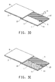
FIG. 3 shows examples of the method and the system. FIG. 3A is an example of the system in an open format with the target coating being applied. FIG. 3B is an example of the system with a target coating applied to a partial hiding. FIG. 3C is an example of the system with a target coating applied to a complete hiding. FIG. 3D and FIG. 3E are examples of the system having one or more target coatings applied.
FIG. 4 show further examples of the system. FIG. 4A is a schematic view of the system with the separation layer (8) being removed and the back support layer (3) being applied to the target coating layer (2). FIG. 4B is a schematic view of the system with target coating layer (2) applied, the removable front support layer (7) removed and the clearcoat layer facing up.
FIG. 5 shows a schematic presentation of one example of illumination and measurement of the target coating layer.
DETAILED DESCRIPTION
The following detailed description is merely exemplary in nature and is not intended to limit the invention or the application and uses of the invention. Furthermore, there is no intention to be bound by any theory presented in the preceding background of the invention or the following detailed description.
The features and advantages of the present invention will be more readily understood, by those of ordinary skill in the art, from reading the following detailed description. It is to be appreciated that certain features of the invention, which are, for clarity, described above and below in the context of separate embodiments, may also be provided in combination in a single embodiment. Conversely, various features of the invention that are, for brevity, described in the context of a single embodiment, may also be provided separately or in any sub-combination. In addition, references in the singular may also include the plural (for example, “a” and “an” may refer to one, or one or more) unless the context specifically states otherwise.
The use of numerical values in the various ranges specified in this application, unless expressly indicated otherwise, are stated as approximations as though the minimum and maximum values within the stated ranges were both proceeded by the word “about.” In this manner, slight variations above and below the stated ranges can be used to achieve substantially the same results as values within the ranges. Also, the disclosure of these ranges is intended as a continuous range including every value between the minimum and maximum values.
As used herein:
“Gloss” means surface gloss of a coating surface and is related to the amount of incident light that is reflected at the specular reflectance angle of the mean of that surface. Gloss can be measured with a specular glossmeter, such as those available from Byk-Gardener, Geretsried, Germany or other locations.
“DOI” (Distinctness of Image) is a quantitative measure of coating appearance that measures the light reflected at and around the specular reflectance angle. It can be determined according to the method described in ASTM D 5767. DOI can be measured with wave scan instruments, such as those available from Byk-Gardener, Geretsried, Germany or other locations. DOI measures not only the amount of incident light that is reflected at the specular reflectance angle, but also the distribution of the reflected light around the reflectance specular angle, typically +/−0.3° from the specular angle. A coating surface that gives fuzzy or distorted image generally produces a low DOI reading. A coating reflecting 100% of lights at the specular angle gives a DOI reading of 100.
The term “hiding” or “hiding power” refers to a coating composition's ability to cover a surface opaquely so that an underlying coating or substrate cannot be seen in visible light. For a pigmented coating composition, hiding typically increases with increasing thickness of the coating layer formed by the coating composition. Hiding can be determined with several known methods such as the method ASTM D 6762-02a. The minimum thickness of a coating layer for a complete hiding is referred to as a “hiding thickness”. A hiding device can have different contrast patterns including high contrast patterns, such as black-and-white patterns.
The term “pigment” or “pigments” used herein refers to a colorant or colorants that produce color or colors. A pigment can be from natural and synthetic sources and can be made of organic or inorganic constituents. A pigment can also include metallic particles or flakes with specific or mixed shapes and dimensions. A pigment is usually not soluble in a coating composition.
The term “effect pigment” or “effect pigments” refers to pigments that produce special effects in a coating. Examples of effect pigments can include, but not limited to, light scattering pigments, light interference pigments, and light reflecting pigments. Flakes, such as metallic flakes, for example aluminum flakes, are examples of such effect pigments. Effect pigments can also include pearlescent pigments.
Gonioapparent flakes refer to flakes which change color or appearance, or a combination thereof, with changing in illumination angle or viewing angle. Metallic flakes, such as aluminum flakes are examples of gonioapparent flakes.
The term “dye” means a colorant or colorants that produce color or colors. Dye is usually soluble in a coating composition.
“Characteristics” of a coating used herein can include color characteristics and appearance characteristics.
The term “appearance” or “appearance characteristics” used herein can include: (1) the aspect of visual experience by which a coating is viewed or recognized; and (2) perception in which the spectral and geometric aspects of a coating is integrated with its illuminating and viewing environment. In general, appearance can include texture, sparkle, or other visual effects of a coating, especially when viewed from varying viewing angles and/or with varying illumination angles. Examples of appearance characteristics can also include, metallic effect, pearlescent effect, gloss, distinctness of image, coarseness, glint and glitter as well as the enhancement of depth or color perception in the coatings imparted by the effect pigments, especially produced by metallic flakes, such as aluminum flakes. Appearance characteristics can be obtained by visual inspection or by using an appearance measurement device.
The term “layer” or “layers” used herein refers to a sheet or a film, in which dimensions of width and length are greater than the dimension of its thickness, sometimes a few orders of magnitude greater. A layer can have two surfaces opposite to each other. A layer can be stand alone or affixed to a substrate or other materials. Examples of layers can include a coating layer, an aluminum foil, a plastic film, a foil formed from polymeric materials, a sheet of paper, or a sheet of glass.
Color characteristics of a coating can include visual aspects of color of the coating, chroma, hue, lightness, darkness, spectral reflectance, L, a, b, L*, a*, b*, X, Y, Z values, L, C, h values, and a combination thereof. The color characteristics can be obtained by visual inspection, or by using a color measurement device such as a colorimeter, a spectrophotometer, or a goniospectrophotometer.
The term “coating” or “coating composition” can include any coating compositions known to those skilled in the art and can include a two-pack coating composition, also known as “2K coating composition”; a one-pack or 1K coating composition; a coating composition having a crosslinkable component and a crosslinking component; a radiation curable coating composition, such as a UV curable coating composition or an E-beam curable coating composition; a mono-cure coating composition; a dual-cure coating composition; a lacquer coating composition; a waterborne coating composition or aqueous coating composition; a solvent borne coating composition; or any other coating compositions known to or developed by those skilled in the art. The coating composition can be formulated as a primer, a basecoat, or a color coat composition and can comprise dyes, pigments or effect pigments. The coating composition can also be formulated as a clearcoat composition. Clearcoat composition can further comprise certain pigments having same or similar optical properties, such as same or similar refractive index as the cured clearcoat. One of such pigments can be transparent silica.
The term “vehicle”, “automotive”, “automobile” or “automotive vehicle” can include an automobile, such as car, bus, truck, semi truck, pickup truck, SUV (Sports Utility Vehicle); tractor; motorcycle; trailer; ATV (all terrain vehicle); heavy duty mover, such as, bulldozer, mobile crane and earth mover; airplanes; boats; ships; and other modes of transport.
An imaging device refers to a device that can capture images under a wide range of electromagnetic wavelengths including visible or invisible wavelengths. Examples of the imaging device can include, but not limited to, a still film optical camera, a digital camera, an X-Ray camera, an infrared camera, an analog video camera, and a digital video camera. A digital imager or digital imaging device refers to an imaging device captures images in digital signals. Examples of the digital imager can include, but not limited to, a digital still camera, a digital video camera, a digital scanner, and a charge coupled device (CCD) camera. An imaging device can capture images in black and white, gray scale, or various color levels.
This invention is directed to a method for obtaining characteristics of a target coating layer. The method can comprise the steps of:
    • a) providing a removable front support layer having a lower surface and an upper surface;
    • b) providing a clearcoat layer having a first surface and a second surface, wherein at least a portion of said lower surface of the front support layer is affixed to said second surface of the clearcoat layer and removable from said clearcoat layer;
    • c) applying a target coating composition over at least a portion of said first surface of the clearcoat layer to form a wet coating layer thereon;
    • d) at least partially curing or drying said wet coating layer to form said target coating layer; and
    • e) obtaining said characteristics of said target coating layer by measuring from the second surface of the clearcoat layer.
The removable front support layer can be produced from plastic, such as thermoplastic polymer or thermoset polymer. The removable front support layer can be a polyester (PE) film, a polyethylene terephthalate polyester (PET) film, a polyvinyl chloride (PVC) film, a polypropene (PP) film, a polystyrene (PS) film, a thermoplastic polyurethanes (TPU) film, or a combination thereof. The removable front support layer can also be produced from paper, other plastic or polymeric materials, metal, glass or any other suitable materials, or a combination thereof. A sheet of paper, a plastic film, a metal film such as an aluminum film or foil, or a combination thereof can be suitable. The removable front support layer can be flexible or non-flexible.
The removable front support layer (7) can have a lower surface (7 a) and an upper surface (7 b). The lower surface (7 a) can be affixed over at least a portion of the second surface (1 b) of the clearcoat layer (1). The removable front support layer (7) can be removed from the clearcoat layer and can comprise a release layer over the lower surface (7 a) for easy removal of the front support layer from the clearcoat layer. In one example, the removable front support layer can be removed after the clearcoat layer is formed from the clearcoat composition. In another example, the removable front support layer can be removed after at least partially curing or drying the target coating layer. The release layer can comprise one or more fluoropolymers. Examples of the fluoropolymers can include polytetrafluoroethylene or derivatives therefrom. Examples of commercially available fluoropolymers can include Teflon® available from DuPont, Wilmington, USA, under registered trademark.
The front support layer can be colorless or colored. The front support layer can be transparent or non-transparent. The front support layer can also have patterns or patches of patterns.
The removable front support layer can have a thickness in a range of from 1 mil to 40 mils (about 25 μm to 1016 μm) in one example, from 5 mil to 30 mils (about 125 μm to 760 μm) in another example, and from 5 mil to 20 mils (about 125 μm to 508 μm) in yet another example.
The clearcoat layer can have a range of gloss levels. The clearcoat layer can have a constant gloss level or a plurality of different gloss levels, or have patterns or strips of different gloss levels across the clearcoat layer. In one example, the clearcoat layer can have two portions (101) and (102) (FIG. 2C) each differing in gloss levels, thickness or a combination thereof. In another example, the clearcoat layer can have multiple portions (103-106) (FIG. 2D) having different gloss levels, different thicknesses, or a combination thereof. The clearcoat layer can also be colorless, tinted or colored.
The clearcoat layer can be produced by a process comprising the steps of:
    • applying at least one clearcoat composition over at least a portion of said lower surface of said removable front support layer to form a wet clearcoat layer thereon; and
    • curing said wet clearcoat layer to form said clearcoat layer.
The clearcoat layer can also be produced by a process comprising the step of:
    • applying two or more clearcoat compositions over one or more portions of said lower surface of said removable front support layer to form said clearcoat layer.
The clearcoat layer can have different properties at different portions such as different colors, gloss levels, or combination thereof. The clearcoat layer can have a constant thickness or a plurality of different thicknesses. In one example, the clearcoat layer can have a constant thickness. In another example, the clearcoat layer can have a wedged variable thickness. In yet another example, the clearcoat layer can have one thickness at one portion and a different thickness at another portion of the clearcoat layer.
The clearcoat layer can comprise one or more clearcoat sub-layers formed from a single or a plurality of clearcoat compositions. In one example, the clearcoat layer can be formed from a single clearcoat composition with one or more sub-layers. In another example, the clearcoat layer can comprise one or more sub-layers formed from one or more different clearcoat compositions. In yet another example, the clearcoat layer can be formed from a single clearcoat composition with different thicknesses at different portions. In yet another example, the clearcoat layer can have one portion formed from one clearcoat composition and a subsequent portion formed from a different clearcoat composition. In yet another example, the clearcoat layer can be formed from two or more clearcoat compositions applied over one or more portions of the lower surface of the removable front support layer.
Any clearcoat compositions known to or developed by those skilled in the art can be suitable for forming the clearcoat layer. Examples of the clearcoat compositions can include two-pack coating composition, one-pack coating composition, coating composition having a crosslinkable component and a crosslinking component, radiation curable coating, mono-cure coating, dual-cure coating, lacquer coating, waterborne coating, or solvent borne coating. Suitable clearcoat compositions can further comprise suitable pigments or other components, such as silica or other transparent pigments. The clearcoat composition can have one or more additives to produce the clearcoat layer having different properties, such as scratch resistance, different levels of gloss, ultraviolet (UV) resistance, or a combination thereof. One example of the additives can include silica or silica derivatives. Further examples of additives can include ultraviolet (UV) light stabilizers, ultraviolet light absorbers, screeners, quenchers, antioxidant, wetting agents, leveling and flow control agents, rheological control agents, flatteners, thickeners, or catalysts. The additives can be used in conventional amounts familiar to those skilled in the art.
The clearcoat composition can also be tinted or colored. In one example, the clearcoat composition can be tinted with one or more tints or other pigments. In another example, the clearcoat composition can be colored with one or more pigments, tints, dyes, or a combination thereof. The clearcoat composition can also have one or more components same or different from the target coating composition mentioned herein. In one example, the clearcoat composition and the target coating composition can have one or more same or different binder components. In another example, the clearcoat composition and the target coating composition can have one or more same or different flatteners.
The clearcoat composition can comprise a polytrimethylene ether diol having a Mn (number average molecular weight) in a range of from 500 to 10,000. Suitable polytrimethylene ether diol can be prepared by an acid-catalyzed polycondensation of 1,3-propanediol, such as described in U.S. Pat. Nos. 6,977,291 and 6,720,459. A bio-route via fermentation of a renewable resource can be used to obtain the 1,3-propanediol. One example of renewable resources is corn since it is readily available and has a high rate of conversion to 1,3-propanediol and can be genetically modified to improve yields to the 1,3-propanediol. Examples of typical bio-route can include those described in U.S. Pat. No. 5,686,276, U.S. Pat. No. 5,633,362 and U.S. Pat. No. 5,821,092. Addition of the polytrimethylene ether diol can enhance flexibility of the clearcoat layer, therefore preventing cracking, chipping or other damage to the clearcoat layer during operation.
Curing of the clearcoat layer can be done at a temperature, time and other conditions suitable for the chosen clearcoat composition. In one example, the clearcoat can be cured at a temperature in a range of from 15° C. to 60° C. For a radiation curable coating, the clearcoat can be exposed to an appropriate radiation source, such as a UV light or e-beam, for a certain period of time suitable for the chosen clearcoat composition.
The clearcoat composition can be applied using any of the coating application techniques known to or developed by those skilled in the art.
The clearcoat layer is transparent and can be colorless, colored or tinted. The clearcoat layer can have a thickness in a range of from 0.1 mil to 40 mils (about 2.5 μm to 1016 μm) in one example, from 0.5 mil to 30 mils (about 12.5 μm to 760 μm) in another example, from 0.5 mil to 20 mils (about 12.5 μm to 508 μm) in yet another example, from 0.5 mil to 10 mils (about 12.5 μm to 254 μm) in yet another example, and from 0.5 mil to 5 mils (about 12.5 μm to 127 μm) in yet another example.
The target coating composition can be any one of the aforementioned coating compositions, such as a two-pack coating composition, a one-pack coating composition, a coating composition having a crosslinkable component and a crosslinking component, a radiation curable coating, a mono-cure coating, a dual-cure coating, a lacquer coating, a waterborne coating, or a solvent borne coating. For a two-pack coating composition, two packages of the coating composition can be mixed immediately prior to applying the coating.
The target coating composition can comprise one or more pigments, one or more effect pigments, or a combination thereof. The effect pigments can comprise one or more metallic pigments, one or more pearlescent pigments, or a combination thereof. Examples of the effect pigment can include aluminum flakes or pearlescent pigments.
The target coating composition can be applied using spraying, brushing, rolling, draw down, or any other conventional coating application techniques known to those skilled in the art. A hiding mark (5), such as the ones available from THE LENETA COMPANY, INC., Mahwah, N.J., USA, can be used to monitor spraying thickness of the target coating layer. The hiding mark can be affixed to the clearcoat layer before applying the target coating layer. The hiding mark can also be placed between the clearcoat layer and the removable front support layer and visible through the clearcoat layer.
The target coating layer can be at least partially cured or partially dried. The target coating layer can also be completely cured or dried. The term “partially curing” or “partially drying” means curing or drying the wet coating layer for a time period that is shorter than the time period required for complete curing or drying of the coating layer. Typically, a short period of time such as in a range of from a few seconds to a few hours can be suitable for at least partially curing or drying a wet coating layer. The target coating layer can be at least partially cured or partially dried at a temperature in a range of from 15° C. to 60° C.
Time or temperature that is required for complete curing or drying the target coating layer can be dependent upon the target coating composition being used. In one example, a few minutes can be suitable for curing or drying one target coating layer. In another example, 10 to 60 minutes can be suitable for curing or drying another target coating layer. In yet another example, a few hours, such as 1 to 20 hours can be suitable for curing or drying yet another target coating layer. In further example, a few days, such as 1 to 7 days can be suitable for curing or drying further another coating layer. For a radiation curable coating, the wet coating layer can be exposed to an appropriate radiation source, such as a UV light or e-beam, for a certain period of time.
The target coating layer can be formed from one or more same or different target coating compositions and can be covering the same or different portions of the clearcoat layer (110-111) (FIG. 3 D-E). The target coating layer can be applied in uniform or different thicknesses. The target coating layer can also comprise one or more coating layers formed from the same or different coating compositions.
The method of this invention can further comprise the step of applying a back support layer (3) having an inner surface (3 a) and an outer surface (3 b) over the target coating layer with the inner surface (3 a) close to the target coating layer. The target coating layer can be positioned between the clearcoat layer and the back support layer.
The back support layer can be made from paper, plastic, polymeric materials, metal, glass or any other suitable materials. The back support layer can be flexible or non-flexible.
The back support layer can comprise a primer layer. Any coating composition suitable for use as a primer can be suitable for forming this primer layer. The primer layer can have one or more layers formed from the same or different coating compositions suitable for use as primers. A primer layer with good hiding property is preferred. In one example, the primer layer can be a grey primer layer. If the back support layer is transparent or semi-transparent, the primer layer can be at either of the two surfaces of the back support layer. If the back support layer is non-transparent, the primer layer can be preferably positioned on the surface of the back support layer facing toward the target coating layer. It can be preferred that the back support layer is non-transparent if the back support layer does not comprise the primer layer or the primer layer has incomplete hiding.
The back support layer can comprise an adhesive layer. Any adhesives or pressure-sensitive adhesives can be suitable. The adhesive layer can be optional. When present, the adhesive layer can be positioned over the inner surface (3 a) of the back support layer so that the back support layer can be bound to the target coating layer via said adhesive layer. In the absence of the adhesive layer, the back support layer can be stacked together with the clearcoat layer so that the target coating layer can be positioned in between. When the adhesive layer is present, the back support layer can further comprise a separation layer (8) to protect the adhesive layer prior to binding of the back support layer and the target coating layer.
The back support layer can comprise a magnetic layer. Any magnetic materials that can form a magnetic layer can be suitable. It is preferred that the magnetic layer is flexible. The commercial available magnetic labels comprising magnets or magnetic polymers can be suitable. In one example, the magnetic layer can form the base of the back support layer wherein the primer layer or the adhesive layer can be applied thereon. In another example, the back support layer can comprise a primer layer, an adhesive layer, a magnetic layer, or a combination thereof.
The back support layer can be applied to the target coating layer by removing the separation layer (8) therefore exposing the adhesive layer and subsequent binding of the back support layer and the target coating layer. In one example, the back support layer having an adhesive layer can be applied by peeling off the separation layer (8) in the direction (9 a) (FIG. 4A) and applying pressure from the outer surface (3 b) towards the target coating layer (2).
The removable front support layer (7) can be removed after the back support layer (3) is applied (FIG. 1D and FIG. 4B).
The characteristics of the target coating layer (2) can be measured from the second surface (1 b) and can be color characteristics, appearance characteristics, or a combination thereof. The characteristics can be obtained by using a color measuring device, an appearance measuring device, or a color-appearance dual measuring device. The color measuring device, the appearance measuring device, or the color-appearance dual measuring device can comprise an imaging device. Examples of the color measurement device can include, such as a colorimeter, a spectrophotometer, or a goniospectrophotometer. The characteristics can also be obtained by visual inspection or observation. The characteristics can be obtained under one or more illumination conditions, including, nut not limited to, illumination light intensities, illumination spectral power distributions, illumination light angles, and a combination thereof. One or more viewing/measurement angles, such as 15°/25°/45°/75°/110° and optionally −15°, can be suitable.
The color characteristics can comprise visual aspects of color of the coating, chroma, hue, lightness, darkness, spectral reflectance, L, a, b, L*, a*, b*, X, Y, Z values, or L, C, h values, or a combination thereof. Spectral reflectance, L, a, b, L*, a*, b*, X, Y, Z values, or L, C, h values, or a combination thereof can be preferred. The appearance characteristics can include, but not limited to, gloss, distinctness of image, coarseness, flake appearances such as texture, sparkle, glint and glitter as well as the enhancement of depth perception in the coatings imparted by the flakes, especially produced by metallic flakes, such as aluminum flakes.
The appearance characteristics can include texture, sparkle, metallic effect, pearlescent effect, gloss, distinctness of image, coarseness, glint and glitter, the enhancement of depth or color perception in the coatings imparted by the effect pigments, or a combination thereof. The appearance characteristics can further include other visual effects of a coating. The appearance characteristics can be obtained by visual inspection or by using an appearance measurement device.
The characteristics of the target coating layer can be obtained by measuring from the second surface of the clearcoat layer and through the clearcoat layer. When the removable front support layer is transparent, the characteristics can be obtained with or without the removable front support layer. It is preferred to remove the removable front support layer prior to obtaining the characteristics of the target coating. One example is shown in FIG. 5. Illumination light (11) can be provided as defused light or at an illumination angle appropriate for the measurement, such as 45°, and can produce reflections from the clearcoat layer's surface (12). Part of the illumination light (11) can travel through the clearcoat layer (1) becoming a refracted light (11 a) and can produce reflections from the target coating layer surface (12 a). Characteristics of the target coating layer (2) can be obtained by measuring from the second surface (1 b) of the clearcoat layer (1) at one or more viewing or measurement points (20). Depending on the surfaces, reflections can be unidirectional or multidirectional. For a high gloss clearcoat, reflections can be unidirectional or very close to unidirectional. For a low gloss or matt coating surface, reflections can be multidirectional. Multi-angle measurement devices that are commercially available can be used to measure the characteristics of the target coating.
In traditional method, in order to measure characteristics of a target coating layer that is protected with a clearcoat, the target coating layer needs to be applied first. Then a clearcoat is applied over the target coating layer. The target coating layer and the clearcoat layer can be cure sequentially or simultaneously. Traditional method requires extra time and effort for applying and curing the clearcoat layer.
The method of this disclosure provides an advantage of fast and accurate measurement of the characteristics of the target coating layer. The clearcoat layer can be premade. Only the formation of the target coating layer is needed, therefore reducing the measurement time and effort. In addition, since the clearcoat layer is formed from a clearcoat composition, the measurement can be more accurate than earlier attempts that use plastic films such as Mylar polyester film. One of such earlier attempts can include the one described in U.S. Pat. No. 5,371,599.
This invention is also directed to a system for obtaining characteristics of a target coating layer. The system can comprise:
i) a clearcoat layer (1) having a first surface (1 a) and a second surface (1 b);
ii) a removable front support layer (7) having a lower surface (7 a) and an upper surface (7 b), said a lower surface (7 a) of the removable front support layer (7) is affixed over at least a portion of said second surface of the clearcoat layer;
iii) a back support layer (3) having an inner surface (3 a) and an outer surface (3 b), at least a portion of said inner surface comprises an adhesive layer thereon; and
iv) a separation layer (8) affixed over at least a portion of said adhesive layer, said separation layer is removable from said adhesive layer.
The removable front support layer and said back support layer can be assembled at a joint edge (10) with said lower surface (7 a) facing said inner surface (3 a), said clearcoat layer and said separation layer can be positioned between said removable front support layer and said back support layer, and wherein said removable front layer and said back support layer can be pivotable around said joint edge to expose said first surface (1 a) of the clearcoat layer.
Aforementioned clearcoat layer, removable front support layer, back support layer, and separation layer can be suitable.
The system can comprise a color measurement device, an appearance measurement device, a color-appearance dual measuring device, or a combination thereof. The system can further comprise an aforementioned hiding mark.
This disclosure is further directed to a method for obtaining characteristics of a target coating layer using the system disclosed herein. The method can comprise the steps of:
A) providing a measurement system comprising;
    • i) a clearcoat layer (1) having a first surface (1 a) and a second surface (1 b);
    • ii) a removable front support layer (7) having a lower surface (7 a) and an upper surface (7 b), said a lower surface (7 a) of the removable front support layer (7) is affixed over at least a portion of said second surface of the clearcoat layer;
    • iii) a back support layer (3) having an inner surface (3 a) and an outer surface (3 b), at least a portion of said inner surface comprises an adhesive layer thereon; and
    • iv) a separation layer (8) affixed over at least a portion of said adhesive layer, said separation layer is removable from said adhesive layer;
B) applying a target coating composition over said first surface of the clearcoat layer to form a wet coating layer thereon;
C) at least partially curing or drying said wet coating layer to form said target coating layer; and
D) obtaining said characteristics of said target coating layer by measuring from the second surface of the clearcoat layer.
The method can further comprise the step of removing said removable front support layer prior to obtaining the characteristics of said target coating layer.
The target coating composition comprises one or more pigments, one or more effect pigments, or a combination thereof. The effect pigments can comprise one or more metallic pigments, one or more pearlescent pigments, or a combination thereof.
The wet coating layer can be cured at a temperature in a range of from 15° C. to 60° C. The characteristics can be color characteristics, appearance characteristics, or a combination thereof. The characteristics can be obtained by using a color measuring device, an appearance measuring device, a color-appearance dual measuring device, or a combination thereof.
While at least one exemplary embodiment has been presented in the foregoing detailed description of the invention, it should be appreciated that a vast number of variations exist. It should also be appreciated that the exemplary embodiment or exemplary embodiments are only examples, and are not intended to limit the scope, applicability, or configuration of the invention in any way. Rather, the foregoing detailed description will provide those skilled in the art with a convenient road map for implementing an exemplary embodiment of the invention, it being understood that various changes may be made in the function and arrangement of elements described in an exemplary embodiment without departing from the scope of the invention as set forth in the appended claims and their legal equivalents.

Claims (20)

What is claimed is:
1. A system comprising:
i) a clearcoat layer (1) having a first surface (1 a) and a second surface (1 b);
ii) a removable front support layer (7) having a lower surface (7 a) and an upper surface (7 b), said lower surface (7 a) of the removable front support layer (7) is affixed over at least a portion of said second surface of the clearcoat layer (1);
iii) a back support layer (3) having an inner surface (3 a) and an outer surface (3 b), at least a portion of said inner surface comprises an adhesive layer thereon; and
iv) a separation layer (8) affixed over at least a portion of said adhesive layer, said separation layer is removable from said adhesive layer.
2. The system of claim 1, wherein said removable front support layer and said back support layer are assembled at a joint edge (10) with said lower surface (7 a) facing said inner surface (3 a), said clearcoat layer and said separation layer are positioned between said removable front support layer and said back support layer, and wherein said removable front layer and said back support layer are pivotable around said joint edge to expose said first surface (1 a) of the clearcoat layer.
3. The system of claim 1, wherein said removable front support layer is produced from thermoplastic polymer, thermoset polymer, paper, metal, glass, or a combination thereof.
4. The system of claim 1, wherein said removable front support layer is a polyester (PE) film, a polyethylene terephthalate polyester (PET) film, a polyvinyl chloride (PVC) film, a polypropene (PP) film, a polystyrene (PS) film, or a thermoplastic polyurethanes (TPU) film, a metal film, or a combination thereof.
5. The system of claim 1, wherein said clearcoat layer is produced by a process comprising the steps of:
applying a clearcoat composition over said lower surface (7 a) of the front support layer to form a wet clearcoat layer; and
curing said wet clearcoat layer to form said clearcoat layer.
6. The system of claim 1, wherein said clearcoat layer is produced by a process comprising the step of:
applying two or more clearcoat compositions over one or more portions of said lower surface of said removable front support layer to form said clearcoat layer.
7. The system of claim 1, wherein said back support layer comprises a primer layer.
8. The system of claim 1, wherein said back support layer comprises a magnetic layer.
9. The system of claim 1 further comprising a color measurement device, an appearance measurement device, a color-appearance dual measuring device, or a combination thereof, wherein said color measurement device, said appearance measurement device, said color-appearance dual measuring device, or said combination thereof are configured to obtain a color characteristic or an appearance characteristic of said second surface.
10. The system of claim 1 further comprising a hiding mark.
11. The system of claim 1, wherein said clearcoat layer has a constant thickness, a plurality of different thicknesses, a constant gloss level, a plurality of different gloss levels, or a combination thereof.
12. The system of claim 1, wherein said clearcoat layer is colorless, colored, or tinted.
13. The system of claim 1, wherein said clearcoat layer is formed from a clearcoat composition comprising a polytrimethylene ether diol polymerized from bio-derived 1,3-propanediol.
14. A method for obtaining characteristics of a target coating layer, said method comprising the steps of:
A) providing a measurement system comprising;
i) a clearcoat layer (1) having a first surface (1 a) and a second surface (1 b);
ii) a removable front support layer (7) having a lower surface (7 a) and an upper surface (7 b), said lower surface (7 a) of the removable front support layer (7) is affixed over at least a portion of said second surface of the clearcoat layer;
iii) a back support layer (3) having an inner surface (3 a) and an outer surface (3 b), at least a portion of said inner surface comprises an adhesive layer thereon; and
iv) a separation layer (8) affixed over at least a portion of said adhesive layer, said separation layer is removable from said adhesive layer;
B) applying a target coating composition over said first surface of the clearcoat layer to form a wet coating layer thereon;
C) at least partially curing or drying said wet coating layer to form said target coating layer; and
D) obtaining said characteristics of said target coating layer by measuring from the second surface of the clearcoat layer.
15. The method of claim 14 further comprising the step of removing said removable front support layer prior to obtaining the characteristics of said target coating layer.
16. The method of claim 14, wherein said target coating composition comprises one or more pigments, one or more effect pigments, or a combination thereof.
17. The method of claim 16, wherein said effect pigments comprise one or more metallic pigments, one or more pearlescent pigments, or a combination thereof.
18. The method of claim 14, wherein said wet coating layer is cured at a temperature in a range of from 15° C. to 60° C.
19. The method of claim 14, wherein said characteristics are color characteristics, appearance characteristics, or a combination thereof.
20. The method of claim 14, wherein said characteristics are obtained by using a color measuring device, an appearance measuring device, a color-appearance dual measuring device, or a combination thereof.
US14/154,360 2009-12-18 2014-01-14 Systems and methods for coating measurement Active US8999429B2 (en)

Priority Applications (1)

Application Number Priority Date Filing Date Title
US14/154,360 US8999429B2 (en) 2009-12-18 2014-01-14 Systems and methods for coating measurement

Applications Claiming Priority (4)

Application Number Priority Date Filing Date Title
US28773709P 2009-12-18 2009-12-18
PCT/US2010/052869 WO2011075212A1 (en) 2009-12-18 2010-10-15 Method for coating measurement
US201213509917A 2012-05-15 2012-05-15
US14/154,360 US8999429B2 (en) 2009-12-18 2014-01-14 Systems and methods for coating measurement

Related Parent Applications (2)

Application Number Title Priority Date Filing Date
PCT/US2010/052869 Division WO2011075212A1 (en) 2009-12-18 2010-10-15 Method for coating measurement
US13/509,917 Division US8771785B2 (en) 2009-12-18 2010-10-15 Method for coating measurement

Publications (2)

Publication Number Publication Date
US20140127395A1 US20140127395A1 (en) 2014-05-08
US8999429B2 true US8999429B2 (en) 2015-04-07

Family

ID=44167646

Family Applications (2)

Application Number Title Priority Date Filing Date
US13/509,917 Active 2030-11-15 US8771785B2 (en) 2009-12-18 2010-10-15 Method for coating measurement
US14/154,360 Active US8999429B2 (en) 2009-12-18 2014-01-14 Systems and methods for coating measurement

Family Applications Before (1)

Application Number Title Priority Date Filing Date
US13/509,917 Active 2030-11-15 US8771785B2 (en) 2009-12-18 2010-10-15 Method for coating measurement

Country Status (5)

Country Link
US (2) US8771785B2 (en)
EP (1) EP2513627B1 (en)
CN (1) CN102667444A (en)
MX (1) MX2012006870A (en)
WO (1) WO2011075212A1 (en)

Cited By (1)

* Cited by examiner, † Cited by third party
Publication number Priority date Publication date Assignee Title
EP4325187A1 (en) 2022-07-28 2024-02-21 Axalta Coating Systems GmbH Method and system for matching color and/or appearance of a surface

Families Citing this family (23)

* Cited by examiner, † Cited by third party
Publication number Priority date Publication date Assignee Title
EP2734591A4 (en) * 2011-07-21 2015-08-26 Coatings Foreign Ip Co Llc Low gloss metallic color coating
US9211695B2 (en) * 2012-05-15 2015-12-15 Palo Alto Research Center Incorporated Low-cost measurement system for photopolymer film polymerization monitoring
US10178351B2 (en) 2012-09-19 2019-01-08 Ppg Industries Ohio, Inc. Multi-angular color, opacity, pigment characterization and texture analysis of a painted surface via visual and/or instrumental techniques
US8879066B2 (en) * 2012-10-26 2014-11-04 Ppg Industries Ohio, Inc. Texture analysis of a painted surface using specular angle data
US10586162B2 (en) * 2013-03-15 2020-03-10 Ppg Industries Ohio, Inc. Systems and methods for determining a coating formulation
US10147043B2 (en) 2013-03-15 2018-12-04 Ppg Industries Ohio, Inc. Systems and methods for texture assessment of a coating formulation
NZ631068A (en) 2013-11-08 2015-10-30 Ppg Ind Ohio Inc Texture analysis of a coated surface using electrostatics calculations
NZ631047A (en) 2013-11-08 2015-10-30 Ppg Ind Ohio Inc Texture analysis of a coated surface using kepler’s planetary motion laws
NZ631063A (en) * 2013-11-08 2015-10-30 Ppg Ind Ohio Inc Texture analysis of a coated surface using cross-normalization
DE102014100594A1 (en) * 2014-01-20 2015-07-23 Isra Surface Vision Gmbh Device for inspection of a material provided with a coated surface and corresponding method
US10450466B2 (en) 2015-10-16 2019-10-22 Polynt Composites USA, Inc. Multilayer coating with visual effect
US10613727B2 (en) 2016-02-19 2020-04-07 Ppg Industries Ohio, Inc. Color and texture match ratings for optimal match selection
US9818205B2 (en) * 2016-02-19 2017-11-14 Ppg Industries Ohio, Inc. Simplified texture comparison engine
CN105954238A (en) * 2016-05-03 2016-09-21 苏州昆岭薄膜工业有限公司 Glossiness test method for testing BOPP compounded film
US11119035B2 (en) 2018-04-26 2021-09-14 Ppg Industries Ohio, Inc. Systems and methods for rapid coating composition determinations
US10970879B2 (en) 2018-04-26 2021-04-06 Ppg Industries Ohio, Inc. Formulation systems and methods employing target coating data results
US11874220B2 (en) 2018-04-26 2024-01-16 Ppg Industries Ohio, Inc. Formulation systems and methods employing target coating data results
US10871888B2 (en) 2018-04-26 2020-12-22 Ppg Industries Ohio, Inc. Systems, methods, and interfaces for rapid coating generation
WO2020124451A1 (en) * 2018-12-19 2020-06-25 深圳先进技术研究院 Thin-film coating chroma analysis device and application thereof, and thin-film coating classification method
WO2020172133A1 (en) * 2019-02-19 2020-08-27 The Chemours Company Fc, Llc Assessment of the applied hiding of a coating
MX2022001141A (en) * 2019-07-29 2022-02-16 Basf Coatings Gmbh Device and method for monitoring the drying/curing process of coatings.
CN111812063B (en) * 2020-07-16 2022-11-04 中国计量大学 Evaluation method and measurement device for metallic paint surface flashing effect
CN116045791B (en) * 2023-04-03 2023-07-21 成都飞机工业(集团)有限责任公司 Metal paint coating thickness assessment method

Citations (26)

* Cited by examiner, † Cited by third party
Publication number Priority date Publication date Assignee Title
US4626474A (en) 1985-06-21 1986-12-02 Stauffer Chemical Company Polyimide film/metal foil lamination
US5151751A (en) 1989-07-19 1992-09-29 Nippon Paint Co., Ltd. Method for evaluating color tone of coating film and device for this evaluation
WO1992022619A1 (en) 1991-06-14 1992-12-23 Minnesota Mining And Manufacturing Company An adhesively appliable flexible film
US5371599A (en) 1993-05-05 1994-12-06 E. I. Du Pont De Nemours And Company Rapid color shading process
US5633362A (en) 1995-05-12 1997-05-27 E. I. Du Pont De Nemours And Company Production of 1,3-propanediol from glycerol by recombinant bacteria expressing recombinant diol dehydratase
US5686276A (en) 1995-05-12 1997-11-11 E. I. Du Pont De Nemours And Company Bioconversion of a fermentable carbon source to 1,3-propanediol by a single microorganism
US6042678A (en) 1992-11-05 2000-03-28 Avery Dennison Corporation Exterior automotive laminate with pressure-sensitive adhesive
US6083335A (en) 1997-08-18 2000-07-04 3M Innovative Properties Company Paint film assembly with masking film and method of making same
US20010023004A1 (en) * 1999-02-24 2001-09-20 Datacard, Inc. Protective coating and methods for making same
US6336988B1 (en) 1995-06-07 2002-01-08 Avery Dennison Corporation Extrusion coating process for making protective and decorative films
US6579397B1 (en) 1987-03-27 2003-06-17 Avery Dennison Corporation Dry paint transfer process for making deep draw high DOI automotive body panels
US6720459B2 (en) 1999-12-17 2004-04-13 E. I. Du Pont Nemours And Company Continuous process for the preparation of polytrimethylene ether glycol
WO2004030939A1 (en) 2002-10-02 2004-04-15 3M Innovative Properties Company Color-matching article
CN1500564A (en) 2002-11-12 2004-06-02 关西涂料株式会社 forming method of pattern coating film and coating ornament
US20040123942A1 (en) 1987-03-27 2004-07-01 Spain Patrick L. Dry paint transfer process for making deep-draw high doi automotive body panels
US20040209057A1 (en) 1995-06-07 2004-10-21 Enlow Howard H. Extruded polymeric high transparency films
US20040258923A1 (en) 2003-03-21 2004-12-23 Sormani Patricia Mary Ellen Coating composition containing polytrimethylene ether diol useful as a clear coat composition and as a primer composition
JP2005071525A (en) 2003-08-27 2005-03-17 Fujitsu Ltd Vertical magnetic recording medium and magnetic storage device
US6905727B2 (en) 2000-12-19 2005-06-14 Akzo Nobel N.V. Method for selecting a formulation for one or more layers of a multi-layer coating
US6977291B2 (en) 1999-12-17 2005-12-20 E.I. Du Pont De Nemours And Company Production of polytrimethylene ether glycol and copolymers thereof
US20060151347A1 (en) 2005-01-10 2006-07-13 Grossman Victor A Packaging and dispensers for adhesive backed elements
US20070098943A1 (en) 2003-02-14 2007-05-03 Avery Dennison Corporation Multi-layer dry paint decorative laminate having discoloration prevention barrier
US20070237891A1 (en) 2006-04-05 2007-10-11 Inoac Corporation Pattern Forming Apparatus and Pattern Forming Method
US20080138627A1 (en) 2006-12-08 2008-06-12 Ppg Industries Ohio, Inc. Color-plus-clear composite coatings
US20080314500A1 (en) 2005-11-15 2008-12-25 Akzo Nobel Coatings International B.V. Process for Preparation of a Multilayer Coating Sheet
US20090213120A1 (en) 2005-04-25 2009-08-27 X-Rite, Inc. Method And System For Enhanced Formulation And Visualization Rendering

Patent Citations (29)

* Cited by examiner, † Cited by third party
Publication number Priority date Publication date Assignee Title
US4626474A (en) 1985-06-21 1986-12-02 Stauffer Chemical Company Polyimide film/metal foil lamination
US6579397B1 (en) 1987-03-27 2003-06-17 Avery Dennison Corporation Dry paint transfer process for making deep draw high DOI automotive body panels
US20040123941A1 (en) 1987-03-27 2004-07-01 Spain Patrick L. Dry paint transfer-lamination process for making high doi automotive body panels
US20040123942A1 (en) 1987-03-27 2004-07-01 Spain Patrick L. Dry paint transfer process for making deep-draw high doi automotive body panels
US5151751A (en) 1989-07-19 1992-09-29 Nippon Paint Co., Ltd. Method for evaluating color tone of coating film and device for this evaluation
WO1992022619A1 (en) 1991-06-14 1992-12-23 Minnesota Mining And Manufacturing Company An adhesively appliable flexible film
US6042678A (en) 1992-11-05 2000-03-28 Avery Dennison Corporation Exterior automotive laminate with pressure-sensitive adhesive
US5371599A (en) 1993-05-05 1994-12-06 E. I. Du Pont De Nemours And Company Rapid color shading process
US5821092A (en) 1995-05-12 1998-10-13 E. I. Du Pont De Nemours And Company Production of 1,3-propanediol from glycerol by recombinant bacteria expressing recombinant diol dehydratase
US5686276A (en) 1995-05-12 1997-11-11 E. I. Du Pont De Nemours And Company Bioconversion of a fermentable carbon source to 1,3-propanediol by a single microorganism
US5633362A (en) 1995-05-12 1997-05-27 E. I. Du Pont De Nemours And Company Production of 1,3-propanediol from glycerol by recombinant bacteria expressing recombinant diol dehydratase
US6336988B1 (en) 1995-06-07 2002-01-08 Avery Dennison Corporation Extrusion coating process for making protective and decorative films
US20040209057A1 (en) 1995-06-07 2004-10-21 Enlow Howard H. Extruded polymeric high transparency films
US6083335A (en) 1997-08-18 2000-07-04 3M Innovative Properties Company Paint film assembly with masking film and method of making same
US20010023004A1 (en) * 1999-02-24 2001-09-20 Datacard, Inc. Protective coating and methods for making same
US6977291B2 (en) 1999-12-17 2005-12-20 E.I. Du Pont De Nemours And Company Production of polytrimethylene ether glycol and copolymers thereof
US6720459B2 (en) 1999-12-17 2004-04-13 E. I. Du Pont Nemours And Company Continuous process for the preparation of polytrimethylene ether glycol
US6905727B2 (en) 2000-12-19 2005-06-14 Akzo Nobel N.V. Method for selecting a formulation for one or more layers of a multi-layer coating
WO2004030939A1 (en) 2002-10-02 2004-04-15 3M Innovative Properties Company Color-matching article
US6995843B2 (en) 2002-10-02 2006-02-07 3M Innovative Properties Company Method of simulating a clear-coat and color-matching articles
CN1500564A (en) 2002-11-12 2004-06-02 关西涂料株式会社 forming method of pattern coating film and coating ornament
US20070098943A1 (en) 2003-02-14 2007-05-03 Avery Dennison Corporation Multi-layer dry paint decorative laminate having discoloration prevention barrier
US20040258923A1 (en) 2003-03-21 2004-12-23 Sormani Patricia Mary Ellen Coating composition containing polytrimethylene ether diol useful as a clear coat composition and as a primer composition
JP2005071525A (en) 2003-08-27 2005-03-17 Fujitsu Ltd Vertical magnetic recording medium and magnetic storage device
US20060151347A1 (en) 2005-01-10 2006-07-13 Grossman Victor A Packaging and dispensers for adhesive backed elements
US20090213120A1 (en) 2005-04-25 2009-08-27 X-Rite, Inc. Method And System For Enhanced Formulation And Visualization Rendering
US20080314500A1 (en) 2005-11-15 2008-12-25 Akzo Nobel Coatings International B.V. Process for Preparation of a Multilayer Coating Sheet
US20070237891A1 (en) 2006-04-05 2007-10-11 Inoac Corporation Pattern Forming Apparatus and Pattern Forming Method
US20080138627A1 (en) 2006-12-08 2008-06-12 Ppg Industries Ohio, Inc. Color-plus-clear composite coatings

Non-Patent Citations (10)

* Cited by examiner, † Cited by third party
Title
ISA USPTO, International Preliminary Report on Patentability for International Application No. PCT/US10/52869, mailed Jun. 28, 2012.
ISA USPTO, International Search Report and Written Opinion for International Application No. PCT/US10/52869, mailed Dec. 20, 2010.
Leneta Company. "Special Substrates for coating Tests/Spray Monitors/Self-Adhering Hiding Power Labels" http://opacity.leneta.com/item/spray-monitors/form-m33-spray-monitor/m33.
Michigan Lake & Stream Associations. "The Secchi Disk-What is it?" Dec. 21, 2007. http://web.archive.org/we2007122121202139/http://www.miswa.org/secchi.htm Para 1-3; figure.
Michigan Lake & Stream Associations. "The Secchi Disk—What is it?" Dec. 21, 2007. http://web.archive.org/we2007122121202139/http://www.miswa.org/secchi.htm Para 1-3; figure.
Response to non-final Office Action for U.S. Appl. No. 13/509,917, dated Nov. 13, 2013.
SIPO, Chinese Office Action issued in Application No. 201080057527.8, dated Dec. 27, 2013.
SIPO, Chinese Second Office Action issued in Application No. 201080057527.8, dated Jun. 18, 2014.
USPTO, Non-final Office Action for U.S. Appl. No. 13/509,917, mailed Aug. 15, 2013.
USPTO, Notice of Allowance for U.S. Appl. No. 13/509,917, mailed Dec. 13, 2013.

Cited By (1)

* Cited by examiner, † Cited by third party
Publication number Priority date Publication date Assignee Title
EP4325187A1 (en) 2022-07-28 2024-02-21 Axalta Coating Systems GmbH Method and system for matching color and/or appearance of a surface

Also Published As

Publication number Publication date
CN102667444A (en) 2012-09-12
EP2513627A1 (en) 2012-10-24
US20140127395A1 (en) 2014-05-08
US8771785B2 (en) 2014-07-08
US20120225190A1 (en) 2012-09-06
EP2513627B1 (en) 2021-06-30
EP2513627A4 (en) 2015-03-04
WO2011075212A1 (en) 2011-06-23
MX2012006870A (en) 2012-06-27

Similar Documents

Publication Publication Date Title
US8999429B2 (en) Systems and methods for coating measurement
CN108699362B (en) Infrared fluorescent paint
CN103827231B (en) Coating system
RU2020124430A (en) COATINGS FOR INCREASING DETECTION DISTANCE TO AN OBJECT DETECTED USING NEAR IR ELECTROMAGNETIC RADIATION
RU2599305C1 (en) Laminated coating film and coated article
EP2721542B1 (en) Method for matching sparkle appearance of coatings
EP3320984B1 (en) Multilayer coating film and coated article
RU2020117438A (en) SUN-REFLECTIVE COATING COMPOSITION
US20140239234A1 (en) System for matching color and coarseness appearance of coatings
WO2013049792A1 (en) Method for matching color and appearance of coatings containing effect pigments
RU2668922C1 (en) Multi-layer film coating and covered object
US20180194111A1 (en) Multilayer coating film and coated article
CN102933317A (en) Laminated coating film structure
CN109789439A (en) Multi-layer coating film and painting object
JP2005169385A (en) Coating method
EP3560706A1 (en) Multilayer coating film and coated object
US20050208292A1 (en) Coating method
US20130288027A1 (en) Multi-layer composite
EP3435047B1 (en) System for matching coarseness appearance of coatings
JP6688784B2 (en) Method for producing elastomer skin having textured surface
JPH0559151B2 (en)
JP5611629B2 (en) Coating method
Amookht et al. The effect of clear coat and basecoat interdiffusion on the appearance of automotive coating system
CN112105696A (en) Multi-layer color and/or effect providing coating and method for forming base paint layer
JP4387165B2 (en) Method for evaluating orientation of pigment in coating film

Legal Events

Date Code Title Description
AS Assignment

Owner name: AXALTA COATING SYSTEMS IP CO. LLC, DELAWARE

Free format text: ASSIGNMENT OF ASSIGNORS INTEREST;ASSIGNORS:STEENHOEK, LARRY EUGENE;RODRIGUES, ALLAN BLASE JOSEPH;BROSMER, GERARD T.;AND OTHERS;SIGNING DATES FROM 20140103 TO 20140108;REEL/FRAME:031960/0295

FEPP Fee payment procedure

Free format text: PAYOR NUMBER ASSIGNED (ORIGINAL EVENT CODE: ASPN); ENTITY STATUS OF PATENT OWNER: LARGE ENTITY

STCF Information on status: patent grant

Free format text: PATENTED CASE

AS Assignment

Owner name: BARCLAYS BANK PLC, AS COLLATERAL AGENT, NEW YORK

Free format text: INTELLECTUAL PROPERTY SECURITY AGREEMENT SUPPLEMENT;ASSIGNOR:AXALTA COATINGS SYSTEMS IP CO. LLC;REEL/FRAME:043532/0063

Effective date: 20170601

MAFP Maintenance fee payment

Free format text: PAYMENT OF MAINTENANCE FEE, 4TH YEAR, LARGE ENTITY (ORIGINAL EVENT CODE: M1551); ENTITY STATUS OF PATENT OWNER: LARGE ENTITY

Year of fee payment: 4

MAFP Maintenance fee payment

Free format text: PAYMENT OF MAINTENANCE FEE, 8TH YEAR, LARGE ENTITY (ORIGINAL EVENT CODE: M1552); ENTITY STATUS OF PATENT OWNER: LARGE ENTITY

Year of fee payment: 8