US8997438B1 - Case packing system having robotic pick and place mechanism and dual dump bins - Google Patents
Case packing system having robotic pick and place mechanism and dual dump bins Download PDFInfo
- Publication number
- US8997438B1 US8997438B1 US13/622,224 US201213622224A US8997438B1 US 8997438 B1 US8997438 B1 US 8997438B1 US 201213622224 A US201213622224 A US 201213622224A US 8997438 B1 US8997438 B1 US 8997438B1
- Authority
- US
- United States
- Prior art keywords
- articles
- bins
- bin
- containers
- conveyor
- Prior art date
- Legal status (The legal status is an assumption and is not a legal conclusion. Google has not performed a legal analysis and makes no representation as to the accuracy of the status listed.)
- Active, expires
Links
Images


Classifications
-
- B—PERFORMING OPERATIONS; TRANSPORTING
- B65—CONVEYING; PACKING; STORING; HANDLING THIN OR FILAMENTARY MATERIAL
- B65G—TRANSPORT OR STORAGE DEVICES, e.g. CONVEYORS FOR LOADING OR TIPPING, SHOP CONVEYOR SYSTEMS OR PNEUMATIC TUBE CONVEYORS
- B65G47/00—Article or material-handling devices associated with conveyors; Methods employing such devices
- B65G47/22—Devices influencing the relative position or the attitude of articles during transit by conveyors
- B65G47/26—Devices influencing the relative position or the attitude of articles during transit by conveyors arranging the articles, e.g. varying spacing between individual articles
- B65G47/30—Devices influencing the relative position or the attitude of articles during transit by conveyors arranging the articles, e.g. varying spacing between individual articles during transit by a series of conveyors
-
- B—PERFORMING OPERATIONS; TRANSPORTING
- B65—CONVEYING; PACKING; STORING; HANDLING THIN OR FILAMENTARY MATERIAL
- B65B—MACHINES, APPARATUS OR DEVICES FOR, OR METHODS OF, PACKAGING ARTICLES OR MATERIALS; UNPACKING
- B65B5/00—Packaging individual articles in containers or receptacles, e.g. bags, sacks, boxes, cartons, cans, jars
- B65B5/08—Packaging groups of articles, the articles being individually gripped or guided for transfer to the containers or receptacles
-
- B—PERFORMING OPERATIONS; TRANSPORTING
- B25—HAND TOOLS; PORTABLE POWER-DRIVEN TOOLS; MANIPULATORS
- B25J—MANIPULATORS; CHAMBERS PROVIDED WITH MANIPULATION DEVICES
- B25J9/00—Programme-controlled manipulators
- B25J9/003—Programme-controlled manipulators having parallel kinematics
- B25J9/0045—Programme-controlled manipulators having parallel kinematics with kinematics chains having a rotary joint at the base
- B25J9/0051—Programme-controlled manipulators having parallel kinematics with kinematics chains having a rotary joint at the base with kinematics chains of the type rotary-universal-universal or rotary-spherical-spherical, e.g. Delta type manipulators
-
- B—PERFORMING OPERATIONS; TRANSPORTING
- B25—HAND TOOLS; PORTABLE POWER-DRIVEN TOOLS; MANIPULATORS
- B25J—MANIPULATORS; CHAMBERS PROVIDED WITH MANIPULATION DEVICES
- B25J9/00—Programme-controlled manipulators
- B25J9/0093—Programme-controlled manipulators co-operating with conveyor means
-
- B—PERFORMING OPERATIONS; TRANSPORTING
- B25—HAND TOOLS; PORTABLE POWER-DRIVEN TOOLS; MANIPULATORS
- B25J—MANIPULATORS; CHAMBERS PROVIDED WITH MANIPULATION DEVICES
- B25J9/00—Programme-controlled manipulators
- B25J9/10—Programme-controlled manipulators characterised by positioning means for manipulator elements
- B25J9/106—Programme-controlled manipulators characterised by positioning means for manipulator elements with articulated links
- B25J9/1065—Programme-controlled manipulators characterised by positioning means for manipulator elements with articulated links with parallelograms
- B25J9/107—Programme-controlled manipulators characterised by positioning means for manipulator elements with articulated links with parallelograms of the froglegs type
-
- B—PERFORMING OPERATIONS; TRANSPORTING
- B65—CONVEYING; PACKING; STORING; HANDLING THIN OR FILAMENTARY MATERIAL
- B65B—MACHINES, APPARATUS OR DEVICES FOR, OR METHODS OF, PACKAGING ARTICLES OR MATERIALS; UNPACKING
- B65B35/00—Supplying, feeding, arranging or orientating articles to be packaged
- B65B35/30—Arranging and feeding articles in groups
- B65B35/50—Stacking one article, or group of articles, upon another before packaging
-
- B—PERFORMING OPERATIONS; TRANSPORTING
- B65—CONVEYING; PACKING; STORING; HANDLING THIN OR FILAMENTARY MATERIAL
- B65B—MACHINES, APPARATUS OR DEVICES FOR, OR METHODS OF, PACKAGING ARTICLES OR MATERIALS; UNPACKING
- B65B35/00—Supplying, feeding, arranging or orientating articles to be packaged
- B65B35/56—Orientating, i.e. changing the attitude of, articles, e.g. of non-uniform cross-section
-
- B—PERFORMING OPERATIONS; TRANSPORTING
- B65—CONVEYING; PACKING; STORING; HANDLING THIN OR FILAMENTARY MATERIAL
- B65G—TRANSPORT OR STORAGE DEVICES, e.g. CONVEYORS FOR LOADING OR TIPPING, SHOP CONVEYOR SYSTEMS OR PNEUMATIC TUBE CONVEYORS
- B65G47/00—Article or material-handling devices associated with conveyors; Methods employing such devices
- B65G47/74—Feeding, transfer, or discharging devices of particular kinds or types
- B65G47/90—Devices for picking-up and depositing articles or materials
- B65G47/91—Devices for picking-up and depositing articles or materials incorporating pneumatic, e.g. suction, grippers
- B65G47/914—Devices for picking-up and depositing articles or materials incorporating pneumatic, e.g. suction, grippers provided with drive systems incorporating rotary and rectilinear movements
-
- Y—GENERAL TAGGING OF NEW TECHNOLOGICAL DEVELOPMENTS; GENERAL TAGGING OF CROSS-SECTIONAL TECHNOLOGIES SPANNING OVER SEVERAL SECTIONS OF THE IPC; TECHNICAL SUBJECTS COVERED BY FORMER USPC CROSS-REFERENCE ART COLLECTIONS [XRACs] AND DIGESTS
- Y10—TECHNICAL SUBJECTS COVERED BY FORMER USPC
- Y10S—TECHNICAL SUBJECTS COVERED BY FORMER USPC CROSS-REFERENCE ART COLLECTIONS [XRACs] AND DIGESTS
- Y10S901/00—Robots
- Y10S901/02—Arm motion controller
- Y10S901/06—Communication with another machine
- Y10S901/07—Conveyor
-
- Y—GENERAL TAGGING OF NEW TECHNOLOGICAL DEVELOPMENTS; GENERAL TAGGING OF CROSS-SECTIONAL TECHNOLOGIES SPANNING OVER SEVERAL SECTIONS OF THE IPC; TECHNICAL SUBJECTS COVERED BY FORMER USPC CROSS-REFERENCE ART COLLECTIONS [XRACs] AND DIGESTS
- Y10—TECHNICAL SUBJECTS COVERED BY FORMER USPC
- Y10S—TECHNICAL SUBJECTS COVERED BY FORMER USPC CROSS-REFERENCE ART COLLECTIONS [XRACs] AND DIGESTS
- Y10S901/00—Robots
- Y10S901/14—Arm movement, spatial
- Y10S901/17—Cylindrical
Definitions
- the present disclosure relates to a case packing system and, more particularly, to a robotic case packing system for loading articles from a moving conveyor into containers, such as corrugated cardboard boxes.
- multi-axis robots have been developed for picking an article off of a common conveyor. Many such multi-axis robots, however, have proven to be fairly slow and heavy. Hence, while such robots may provide greater flexibility in motion, they have also provided a need for an even greater number of robots to meet the speed requirements in the marketplace today. Additionally, it has been found that with some three-axis robots, the range of movement may be limited in certain directions. For example, certain three-axis robots are very limited in their vertical component, which can make movement of an article from a conveyor into a deep container difficult to perform.
- a multi-axis robot as disclosed in Applicant's U.S. Pat. No. 7,644,558, which is fully incorporated herein by reference, can be used for picking an article off of a common conveyor and placing the article in a container.
- the multi-axis robot can provide the desired speed of operation with the desired range of movement and can accurately pick articles from the conveying system and place them into containers.
- a robotic case packing system loads articles from a moving conveyor system into containers.
- a robotic pick and place mechanism is disposed above the articles conveyed on an article conveyor and is disposed in between first and second rotatable (i.e., pivoting or tiltable) bins situated next to the article conveyor.
- a controller operates the system and moves the pick and place mechanism in three axes in two sets of picking movements.
- first picking movements the mechanism picks and places the articles from the conveyor into the first bin while the first bin is in its set or upright position.
- the controller rotates (i.e., pivots or tilts) the first bin from the set position, to a pivoted position, and then back to the set position.
- the bin allows the articles stacked in the first bin to slip into a container held below the first bin on a case conveyor. In this way, the stacked articles stand up in the open container, which can be later closed and sealed.
- the mechanism picks and places the articles from the conveyor into the second bin in second picking movements.
- the controller rotates (i.e., pivots or tilts) the second bin from the set position, to a pivoted position, and then back to the set position to fill another container on the case conveyor with the stacked articles.
- the controller pivots the first bin during the second picking movements used to fill the second bin.
- the controller pivots the second bin during the first picking movements used to fill the first bin.
- the first and second bins can pivot about an axis parallel to or perpendicular to the conveyance direction of the conveyed articles, and each of the bins can have a flap or lid actuated to squeeze or compress the product to eliminate any slippage of the product while pivoting the bins to load the container.
- the flap or lid can be relaxed to allow the product to be loaded into the container. In this way, the articles can slip out an open side of the bin.
- the flap or lid can also squeeze or compress the articles in the bin, which can help the articles to better fit standing up in the container.
- the controller can use sensors for sensing passage of the articles on the article conveyor and can control the speed of the article conveyor. Additionally, the controller can control the position of the containers on the case conveyor and can use actuatable stops and other mechanisms to properly position the containers below the bins.
- the robotic mechanism can be a three-axis robot, such as a delta robot, having at least three actuators moving a handler in three perpendicular directions relative to the conveyance direction of the conveyed articles.
- the robotic mechanism can be a two-axis robot that can be pivoted about an axis so the mechanism can move a handler in three axes.
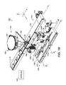
- FIG. 1A is a perspective view of one embodiment of a robotic case packing system of the present disclosure having one type of robotic mechanism for picking and placing articles.
- FIG. 1B is a perspective view of another embodiment of a robotic case packing system of the present disclosure having another type of robotic mechanism for picking and placing articles.
- FIG. 2 is a flowchart showing operation of the disclosed system.
- FIGS. 3A-3B are schematic side views of the disclosed system during stages of operation.
- FIG. 3C is a schematic end view of the disclosed system during stages of operation.
- FIG. 4A is an isometric view of one particular embodiment of a pick and place mechanism for the robotic case packing system of the present disclosure.
- FIG. 4B is an exploded isometric view of the pick and place mechanism of FIG. 4B .
- a robotic case packing system 100 includes an article conveyor 110 , a case conveyor 130 , a control system 102 (shown schematically), and a pick and place mechanism 120 .
- the robotic case packing system 100 uses the pick and place mechanism 120 to alternatingly pick articles 10 from the article conveyor 110 with a handler 128 and stack the picked article(s) 10 into one of two dump bins 140 a - b .
- the system 100 rotates (i.e., pivots or tilts) the dump bins 140 a - b to place the articles 10 into containers 20 (e.g., boxes) moved in position on the case conveyor 130 below.
- the articles 10 can be packages, bags, boxes, or any other type of item or product that can be loaded onto the article conveyor 110 .
- the pick and place mechanism 120 uses a multi-axis robotic device 150 having a two-axis robot 160 and a pivot 170 to move the handler 128 in three axes (X, Y, Z) similar to the multi-axis robot disclosed in Applicant's incorporated U.S. Pat. No. 7,644,558. Particular details of this multi-axis robotic device 150 are provided later.
- the pick and place mechanism 120 uses a three-axis robotic device 180 having a head 182 and a number of arms 184 to move the handler 128 in three axes (X, Y, Z).
- a suitable type of three-axis robotic device is the ABB Flexpicker system or any comparable delta robot, such as described in U.S. Pat. No. 4,976,582.
- any suitable type of robotic mechanism can be used and can be actuated by pneumatics, electricity, hydraulics, or the like.
- the handler 128 on the pick and place mechanism 120 can use a suction cup, a mechanical gripper, or other device to pick up and release the articles 10 .
- the handler 128 can be a vacuum pick assembly for selectively vacuuming and holding an article or articles 10 from the conveyor 110 and subsequently releasing the articles 10 when desired. It will be appreciated by those of skill in the art that other devices for handling the articles 10 may be used.
- the pick and place mechanism 120 is disposed above the article conveyor 130 with dump bins 140 a - b positioned roughly on either side of the mechanism's vertical axis Z.
- the dump bins 140 a - b are disposed next to the article conveyor 110 and positioned above the case conveyor 130 .
- the system 100 operates in an alternating fashion with the two dump bins 140 a - b as described below.
- the controller 102 selectively actuates the pick and place mechanism 120 to move to the article conveyor 110 and pick up an article or articles 10 , following which the pick and place mechanism 120 moves to one of the dump bins 140 a - b . This is repeated as many times as need to fill the dump bin 140 a - b , at which point the controller 102 pivots the dump bin 140 a - b to deposit the articles 10 into a container 20 on the case conveyor 130 . (Although not separately labeled, the dump bins 140 a - b have necessary actuators and other components to pivot the bins 140 a - b .)
- the controller 102 preferably fills one of the dump bins (e.g., 140 a ) the pick and place mechanism 120 while the other full bin (e.g., 140 b ) is being pivoted and repeats this operation the other way around, filing the recently emptied bin (e.g., 140 b ) with pick and place mechanism 120 while dumping the just filled bin (e.g., 140 a ).
- the controller 102 includes one or more processing unit and memory and uses software to operate the various functions of the system 100 .
- the controller 102 can use a combination of any number of commercially available software packages and sensing mechanisms available in the marketplace for use with a two-axis-robot and a servo motor.
- available automation software and controls can be used in conjunction with the robotics to actuate and control the motion of the pick and place mechanism 120 in response to input from stimuli, such as from a photo cell or other sensor 116 .
- the article conveyor 110 delivers articles 10 in a spaced manner (which spacing may be regular or random). Preferably, the delivery is at a known, constant speed, but this is not strictly necessary.
- the article conveyor 110 can use a geared belt similar to a timing belt with an encoder.
- sensors e.g., 116 : FIG. 1B
- the sensor 116 can use any suitable imaging systems and can even determine the placement of articles 10 across the width of the conveyor 10 so the articles 10 do not need to be individually conveyed in a line.
- a set of combining conveyors 115 separately operated by motors 117 combine several articles 10 together on the article conveyor 110 so the wider handler 128 can grip the set of articles 10 together for placing in the bins 140 a - b .
- the articles 10 on the conveyor 110 are individually spaced, picked, and placed. Other options for conveying the articles 10 can be used as will be appreciated.
- the pick and pack mechanism 120 picks up articles 10 from the article conveyor 110 and stacks the articles 10 one on top of another in one of the dump bins 140 a - b at a time.
- a given dump bin 140 a - b is pivoted 90-degrees so that the stacked articles 10 slip out the open side of the dump bin 140 a - b and into a container 20 positioned below on the case conveyor 130 .
- the articles 10 are placed flat in the bins 140 a - b , being stacked by the pick and place mechanism 120 from the article conveyor 10 .
- a mechanized flap or lid 142 closes over the open end of the bin 140 a - b , and the bin 140 a - b is tilted 90-degrees to place an open side of the bin 140 a - b over the open top of the container 20 .
- the stacked articles 10 then slide out of the bin 140 a - b and land in the container 20 . Because the articles 10 may be flat and can be stacked flat on top of one another in the dump bins 140 a - b , the articles 10 fill the container 20 standing up inside the containers 20 .
- the flap 142 can also squeeze or compress the articles 10 in the bin 140 a - b , which can help them to better fit standing up in the container 20 .
- the system 100 can fill containers 20 with stacked articles 10 standing up inside as noted above. This can be the preferred way to pack certain types of articles 10 in the containers 20 . Other articles and products may preferably be laid and stacked flat inside the containers 20 .
- the system 100 of FIGS. 1A-1B can convert readily to pick and place articles 10 flat in the containers 20 as opposed to standing in the containers 20 as depicted here.
- the bins 140 a - b and the associated mechanisms e.g., motors, actuators, etc.
- the pick and place mechanism 120 using its programming can then pick articles 10 from the conveyor 110 and place the articles 10 flat inside the containers 20 on the case conveyor 130 . Adjusting the height of the case conveyor 130 can further facilitate this conversion.
- a support frame (not shown) supports the pick and place mechanism 120 relative to the conveyors 110 , 130 so the mechanism 120 can move the handler 128 along a desired path of operation to selectively pick the articles 10 from the article conveyor 110 and place the articles 10 in the bins 140 a - b over the case conveyor 130 .
- the support frame (not shown) can have any of a variety of shapes and configurations suitable for providing requisite stability and support for the pick and place mechanism 120 . That is, the support frame may be a stand-alone frame that is operatively associated with the conveyors 110 , 130 to properly align the pick and place mechanism 120 with the conveyors 110 , 130 . Alternatively, the support frame may be part of a framework attached to a building in which the case packing system 100 is housed and utilized.
- the system 100 can use any of a number of readily available and suitable conveyor systems that deliver articles 10 and containers 20 at a desired rate for handling.
- the article conveyor 110 positions below and slightly to one side of the pick and place mechanism 120 and can have a conveyor belt 112 moved by a motor 114 .
- the case conveyor 130 positions below and slightly to one side of the pick and place mechanism 120 and can have a conveyor belt 132 moved by a motor 134 .
- either one or the both of the conveyors 110 and 130 can have systems using actuatable rollers or other suitable type of conveyance mechanism.
- the case conveyor 130 positions parallel to the article conveyor 110 .
- the case conveyor 130 is further positioned to be a pre-selected distance from the article conveyor 110 and to be horizontally below the article conveyor 110 to accommodate movement by the pick and place mechanism 120 that is both over the article conveyor 110 and downward to the case conveyor 130 .
- the case conveyor 130 has an inside rail 136 that properly places the containers 20 under the bins 140 a - b and has a biased rail 138 the pushes the containers 20 against the inside rail 136 .
- the case conveyor 130 moves corrugated cardboard cases or similar containers 20 in a conveyance direction X 2 parallel to the conveyance direction X 1 of the article conveyor 110 . (Although parallel and shown traveling in the same orientation, the directions X 2 , X 2 may travel opposite to one another.)
- the case conveyor 130 moves the containers 20 to pre-selected spots to receive the articles 10 from the dump bins 140 a - b .
- Actuated stops 135 on the case conveyor 130 stops the containers 20 at the locations below the dump bins 140 a - b .
- the case conveyor 130 may also include a case erector (not shown) for constructing corrugated cardboard cases or similar containers and moving them to the desired position for receipt of articles.
- the dump bins 140 - b can rotate (i.e., pivot or tilt) in any suitable direction.
- the bins 140 a - b can pivot in the direction of the article conveyor 110 as shown in FIG. 1B .
- the bins 140 a - b as shown in FIG. 1A can pivot toward or away from the article conveyor 110 to dump the articles 10 .
- the bins 140 a - b in FIG. 1A pivot about an axis R parallel to the conveyed directions X 1 , X 2 of the conveyors 110 and 130 .
- the bins 140 a - b are positioned next to one another and turn about the rotational axes R toward the article conveyor 110 from an upright position (e.g., 140 a ) to a pivoted position (e.g., 140 b ).
- actuatable stops 135 along the inside rail 136 stop the movement of both containers 20 at the same time along the conveyed direction X 2 on the conveyor 130 so they are properly positioned beneath the bin's 140 a - b in their pivoted positions.
- the bins 140 a - b in FIG. 1B pivot about axes R a , R b perpendicular to the parallel conveyed directions X 1 , X 2 of the conveyors 110 and 130 .
- the bins 140 a -b are distanced from one another and turn with the conveyed directions X 1 , X 2 from an upright position (e.g., 140 a ) to a pivoted position (e.g., 140 b ) about the rotational axes R a , R b .
- FIG. 2 discusses a packing process 200 shown in FIG. 2 .
- the controller 102 operates the article conveyor 110 moving the articles 10 next to the pick and place mechanism 150 (Block 202 ).
- the pick and place mechanism 120 uses the multi-axis robotic device 150 having the two-axis robot 160 and pivot 170 of FIG. 1A , but the process 200 would apply equally as well to the embodiment having the three-axis robotic device 180 of FIG.
- the controller 102 controls the speed of the conveyor 110 and the mechanism 120 based on sensing the movement of the articles 10 with the sensor 116 , such as a photo cell or other imaging system (Block 204 ).
- the controller 102 also controls the position of the containers 20 on the case conveyor 130 , positioning the containers 20 below the dump bins 140 a - b . Delivery of the containers 20 can be controlled by operating the conveyor 130 and one or more stops 135 a - b . A sensor 117 can also be used as part of this process to position the containers 20 . (For convenience, the containers 20 are depicted as separated, but could equally be held together depending on the bins' rotation.)
- the controller 102 moves the articles 10 on the conveyor 110 and senses the articles 10
- the controller 102 operates the pick and place mechanism 120 by first picking and placing the articles 10 from the article conveyor 110 into the first dump bin 140 a (Block 210 ).
- FIG. 3A shows generic movement of the pick and place mechanism 120 during this first pick and place operation
- FIG. 3C shows the generic movement of the mechanism 120 to and from the conveyor 110 .
- the movements are represented by the end positions, one end position at the conveyor 110 to pick an article 10 and one end position at the first bin 140 a to place the article 10 .
- the picking and placing continues until the first bin 140 a is full (Decision 212 ).
- the controller 102 actuates a holder 142 over the open top of the bin 140 a and pivots the bin 140 a so the stacked articles 10 fill the container 20 a below on the case conveyor 130 (Block 214 ).
- rotation of the bins 140 a - b is depicted about axes R a , R b perpendicular to the conveyors 110 , 130 , but could equally be about the other axis of rotation parallel to the conveyors 110 , 130 .
- the controller 102 operates the pick and place mechanism 120 by then picking and placing the articles 10 from the article conveyor 110 into the second dump bin 140 b in a second pick and place operation (Block 220 ).
- FIG. 3B shows movement of the pick and place mechanism 120 in the end positions at the conveyor 110 and at the second bin 140 b .
- the picking and placing continues until the second bin 140 b is full (Decision 222 ).
- the controller 102 dumps the second bin 140 a so that the stacked articles 10 fill the container 20 b below on the case conveyor 130 (Block 224 ).
- the controller 102 operates the case conveyor 130 to move the containers 20 a - b (Block 226 ) to be closed and sealed, for example. At this point, the controller 102 now positions empty containers 20 a - b on the case conveyor 130 below the dump bins 140 a - b and the process 200 continues as before.
- the pick and place mechanism 120 can fill one dump bin 140 a - b at one time and can subsequently switch to fill the other dump bin 140 b .
- the pick and place mechanism 120 can alternatingly pick and place articles in both of the bins 140 a - b at the same time.
- the sequential operation of filling one bin 140 a and then the other 140 b is preferred because the full dump bin 140 a - b can be pivoted to empty articles 10 into one of the containers 20 while the other bin 140 a - b is being filled by the pick and place mechanism 120 . In this way, the pick and place mechanism 120 does not have down time when it has to wait for dumping of the bins 140 a - b in unison.
- the system 100 can use a combination of alternating and sequential filling of the bins 140 a - b .
- filling of the bins 140 a - b can first be alternated. Then, when the first of the bins 140 a - b is filled, sequential filling of the other, unfilled bin 140 a - b can be performed while the full bin 140 a - b is pivoted.
- the programming of the system 100 can be based on the number of articles 10 needed to fill the bins 140 a - b , how fast the bins 140 a - b can dump stacked articles 10 , and whether the robotics of the pick and place mechanism 120 benefits from repeating sequentially movements or making alternating movements.
- FIGS. 4A-4B shows a multi-axis robotic device 150 similar to that disclosed in incorporated U.S. Pat. No. 7,644,558 for use in the pick and place mechanism 120 in the disclosed system.
- the multi-axis robotic device 150 includes a two-axis robot 160 and a pivot 170 .
- the two-axis robot 160 has a body 162 , linkage arms 166 , and a handler 128 .
- the two-axis robot 160 can move the handler 128 in a first direction D 1 parallel to a conveyance direction (X 1 ) of the conveyed articles and in a second direction D 2 toward and away from the body 162 .
- the range of motion provided by the two-axis robot 160 in the second direction D 2 may be particularly useful in placing articles ( 10 ) in a bin 140 a - b , which can be relatively deep in some implementations.
- the pivot 170 supports the body 162 and rotates the two axis robot 160 about an axis of rotation R parallel to the first direction D 1 .
- the robot's second direction D 2 of movement rotates about the axis of rotation R.
- the handler 128 can be moved in a third direction D 3 perpendicular to the first and second directions D 1 and D 2 .
- the multi-axis robotic device 150 includes a servo motor 152 connected to a gear box 154 , which in turn connects to a gear box shaft 156 .
- the servo motor 152 and gear box 154 connect to a fixed frame (not shown) using flanges 158 or similar supporting structure for securing the gear box 154 and motor 152 to the fixed frame.
- the body 162 of the robot 160 includes a pivot weldment 162 supported on a pivot drive shaft 171 for rotational movement in relation to the pivot weldment 162 .
- the pivot weldment 162 and pivot drive shaft 171 are mounted to the fixed frame (not shown) by means of bearings 164 , which are disposed at each end of the pivot drive shaft 171 and operatively connected to the pivot weldment 162 and the pivot drive shaft 171 such that the housings for the bearings 164 are secured in a stationary manner to the frame, while the pivot drive shaft 171 and the pivot weldment 162 are permitted to pivot or rotate about the axis of rotation R defined by the pivot drive shaft 171 .
- the linkage 166 and other components of the two-axis robot 160 are mounted on the pivot drive shaft 171 along the axis of rotation R such that movement of the two-axis robot 160 along its two directions D 1 and D 2 of movement occurs within planes substantially parallel to the axis of rotation R of the pivot drive shaft 171 .
- the handler 128 is attached to the linkages 166 of the two-axis robot 160 for attaching to and gripping an article ( 10 ) from the article conveyor ( 110 ).
- the handler 128 can be a vacuum pick head suitable for securing the anticipated article for which the case packing system 100 is designed.
- the multi-axis robotic device 150 further includes a drive linkage 172 ( FIG. 4B ) operatively connected between the servo motor 152 and the pivot drive shaft 171 to selectively rotate the pivot drive shaft 171 when desired.
- the drive linkage 172 can use any of a number of suitable drive mechanisms adapted for use between drive shafts such as the gear box drive shaft 156 and the pivot drive shaft 171 to translate the rotation of the gear box drive shaft 156 into desired rotation of the pivot drive shaft 171 .
- the drive linkage 172 has a first pulley 173 connected to the gear box drive shaft 156 by a suitable bushing 174 .
- the drive linkage 172 also includes a second pulley 176 suitably connected to the pivot drive shaft 171 by an appropriate hub 178 and locking assembly 179 as shown in FIG. 4B in exploded detail.
- the diameters of the pulleys 173 and 176 are each selected to provide the corresponding translation of rotation of the gear box pulley 173 and to rotation of the pivot drive shaft pulley 176 .
- a drive belt 175 is disposed over the pulleys 173 and 176 to provide the requisite translation of rotation between the pulleys 173 and 176 .
- articles ( 10 ) are advanced along the article conveyor ( 110 ) where they are sensed by a photo cell or other optical sensor ( 116 : FIG. 1B ) operatively associated with the controller ( 102 ).
- the controller ( 102 ) then actuates the servo motor 152 to pivot the two-axis robot 160 about the pivot drive shaft 171 around the axis of rotation R so that the handler 128 is aligned over the article conveyor ( 110 ).
- the controller ( 102 ) also actuates the two-axis robot 160 to cause downward movement of the handler 128 to engage an article ( 10 ).
- the two-axis robot 160 is then pivoted outwardly around the axis of rotation R defined by the pivot drive shaft 171 . At the same time, the two-axis robot 160 is shifted to either the front or back positions relative to the front or back dump bins 140 a - b.
- the handler 128 holding an article ( 10 ) swings over one of the dump bins (i.e., the front bin 140 a ).
- Containers 20 on the case conveyor 110 are advanced toward the front of the dump bins.
- the two-axis robot 160 is actuated to lower the article 10 both downwardly into the bin 140 a - b to selectively deposit the article 10 in the bin 140 a - b .
- the two-axis-robot 160 is then lifted and rotated and shifted back to engage another article 10 on the article conveyor 110 .
- the speed of a two-axis-robot 160 provides planer movement of the article handler 128 to engage, pick, and place an article 10 .
- the third degree of motion is provided by oscillating or pivoting the two-axis robot 160 back-and-forth a selected distance about the axis of rotation R.
- one pick and place mechanism 120 is shown.
- two or more pick and place mechanisms 120 may be positioned and aligned along the article conveyor 110 to increase the quantity of articles 10 that may be handled off the conveyor 110 .
- the first mechanism may, for example, pick up the first, third, fifth, etc. article 10 on the article conveyor 110 ; and the second pick and place mechanism may pick up the second, fourth, sixth, etc. article 10 on the article convey 110 .
- the number of articles 10 that each mechanism picks up before passing on an article 10 will depend on the article rate, and has substantial flexibility.
- each mechanism 120 in the line pick up as many articles 10 in a row as it is able to pick before passing on an article 10 .
- the use of two or more pick and place mechanisms 120 aligned along the article conveyor 110 thereby enables the handling of a multiple number of articles 10 in the same amount of time. Additionally, the number of articles 10 that may be loaded into each container 20 is not affected by the number of pick and place mechanisms 120 as sometimes the case with prior devices. It will be appreciated by those of skill in the art in light of the present disclosure that yet additional pick and place mechanisms 120 may be aligned along the conveyor in accordance with the present invention in order to increase the speed of handling. Through the use of additional mechanisms 120 , the only limitation on the number of articles that may be handled is the speed of the conveyor 110 .
Abstract
Description
Claims (22)
Priority Applications (1)
| Application Number | Priority Date | Filing Date | Title |
|---|---|---|---|
| US13/622,224 US8997438B1 (en) | 2012-09-18 | 2012-09-18 | Case packing system having robotic pick and place mechanism and dual dump bins |
Applications Claiming Priority (1)
| Application Number | Priority Date | Filing Date | Title |
|---|---|---|---|
| US13/622,224 US8997438B1 (en) | 2012-09-18 | 2012-09-18 | Case packing system having robotic pick and place mechanism and dual dump bins |
Publications (1)
| Publication Number | Publication Date |
|---|---|
| US8997438B1 true US8997438B1 (en) | 2015-04-07 |
Family
ID=52744948
Family Applications (1)
| Application Number | Title | Priority Date | Filing Date |
|---|---|---|---|
| US13/622,224 Active 2033-12-13 US8997438B1 (en) | 2012-09-18 | 2012-09-18 | Case packing system having robotic pick and place mechanism and dual dump bins |
Country Status (1)
| Country | Link |
|---|---|
| US (1) | US8997438B1 (en) |
Cited By (49)
| Publication number | Priority date | Publication date | Assignee | Title |
|---|---|---|---|---|
| US20150059286A1 (en) * | 2013-09-05 | 2015-03-05 | Khs Gmbh | Retail-ready packaging of pouched product |
| US20160039550A1 (en) * | 2014-08-05 | 2016-02-11 | Premier Tech Technologies Ltee | Apparatus and method for grouping and positioning items |
| US9334081B2 (en) * | 2012-02-22 | 2016-05-10 | Stephen Derby | Folding side-wall container and automated system of use |
| US20160368136A1 (en) * | 2014-03-18 | 2016-12-22 | Abb Schweiz Ag | Compact Parallel Kinematics Robot |
| JP2017065749A (en) * | 2015-09-30 | 2017-04-06 | 紀伊産業株式会社 | Sorting device |
| WO2017140920A1 (en) * | 2016-02-17 | 2017-08-24 | LYTZHOFT, Lone | Parallel robot and facility for palletising bags |
| CN107127271A (en) * | 2016-02-29 | 2017-09-05 | 广东唐城美特智能工具有限公司 | The automatic production alignment apparatus of N nails |
| ITUA20162702A1 (en) * | 2016-04-19 | 2017-10-19 | Tiber Pack S R L | PROCESS OF FORMING AND FILLING CARDBOARD BOXES, PARTICULARLY LOADED FROM THE TOP. |
| KR101804417B1 (en) | 2016-05-16 | 2017-12-04 | (주)흥아기연 | Line-up device for packaging blister |
| JP2018002364A (en) * | 2016-06-29 | 2018-01-11 | キユーピー株式会社 | Container processing device |
| US20180016041A1 (en) * | 2016-07-12 | 2018-01-18 | Ishida Co., Ltd. | Boxing apparatus |
| US20180029729A1 (en) * | 2016-07-26 | 2018-02-01 | Yuhannci Co., Ltd. | Auto-packing apparatus for pouch |
| US20180265234A1 (en) * | 2015-10-08 | 2018-09-20 | Gima S.P.A. | Station for inserting products into box-like bodies of different types |
| US20180265311A1 (en) * | 2017-03-17 | 2018-09-20 | Berkshire Grey Inc. | Systems and methods for processing objects including a linear gantry system |
| US10086510B1 (en) * | 2017-07-07 | 2018-10-02 | Fallas Automation, Inc. | Dual robotic case packing system for standup product |
| US20190071196A1 (en) * | 2016-03-01 | 2019-03-07 | Ishida Co., Ltd. | Boxing device |
| US20190084701A1 (en) * | 2015-10-08 | 2019-03-21 | Gima S.P.A. | Machine for forming and filling box-like bodies of different types |
| WO2019077928A1 (en) * | 2017-10-20 | 2019-04-25 | 株式会社京都製作所 | Article transferring device |
| US20190164374A1 (en) * | 2017-11-27 | 2019-05-30 | Glory Ltd. | Sheet handling machine and sheet handling method |
| US10438034B2 (en) | 2017-04-18 | 2019-10-08 | Berkshire Grey, Inc. | Systems and methods for processing objects including space efficient distribution stations and automated output processing |
| US20190369600A1 (en) * | 2016-10-12 | 2019-12-05 | Abb Schweiz Ag | Method And A System For Controlling A Velocity Of A Conveyance Path |
| US10538394B2 (en) | 2016-11-28 | 2020-01-21 | Berkshire Grey, Inc. | Systems and methods for providing singulation of objects for processing |
| US20200031575A1 (en) * | 2015-06-11 | 2020-01-30 | Autostore Technology AS | Storage system with robot device |
| US20200039676A1 (en) * | 2018-08-02 | 2020-02-06 | The Recon Group LLP | System and methods for automatic labeling of articles of arbitrary shape, size and orientation |
| US10576621B2 (en) | 2017-03-23 | 2020-03-03 | Berkshire Grey, Inc. | Systems and methods for processing objects, including automated mobile matrix bins |
| WO2020055903A1 (en) * | 2018-09-10 | 2020-03-19 | Fanuc America Corporation | Robot calibration for ar and digital twin |
| US10611021B2 (en) | 2017-03-23 | 2020-04-07 | Berkshire Grey, Inc. | Systems and methods for processing objects, including automated mobile matrix carriers |
| US20200122869A1 (en) * | 2017-11-06 | 2020-04-23 | JLS Automation | Method and System For Packaging A Container |
| JPWO2019035325A1 (en) * | 2017-08-16 | 2020-07-30 | 株式会社イシダ | Boxing equipment |
| US10792706B2 (en) | 2017-04-24 | 2020-10-06 | Berkshire Grey, Inc. | Systems and methods for providing singulation of objects for processing using object movement redistribution |
| US10793375B2 (en) | 2016-11-08 | 2020-10-06 | Berkshire Grey, Inc. | Systems and methods for processing objects |
| US10875057B2 (en) | 2016-12-06 | 2020-12-29 | Berkshire Grey, Inc. | Systems and methods for providing for the processing of objects in vehicles |
| US10913612B2 (en) | 2017-10-27 | 2021-02-09 | Berkshire Grey, Inc. | Discontinuous grid system for use in systems and methods for processing objects including mobile matrix carrier systems |
| US11055504B2 (en) | 2017-04-18 | 2021-07-06 | Berkshire Grey, Inc. | Systems and methods for separating objects using a vacuum roller with one or more object processing systems |
| US11080496B2 (en) | 2017-04-18 | 2021-08-03 | Berkshire Grey, Inc. | Systems and methods for separating objects using vacuum diverts with one or more object processing systems |
| CN113613999A (en) * | 2019-01-10 | 2021-11-05 | Abb瑞士股份公司 | Packaging unit and method |
| US11200390B2 (en) | 2017-04-18 | 2021-12-14 | Berkshire Grey, Inc. | Systems and methods for separating objects using drop conveyors with one or more object processing systems |
| US11205059B2 (en) | 2017-04-18 | 2021-12-21 | Berkshire Grey, Inc. | Systems and methods for separating objects using conveyor transfer with one or more object processing systems |
| US11242211B2 (en) * | 2018-10-19 | 2022-02-08 | Volm Companies, Inc. | Bin packing system and method |
| US11247798B2 (en) * | 2018-06-11 | 2022-02-15 | Ishida Co., Ltd. | Box packing apparatus |
| WO2021260154A3 (en) * | 2020-06-24 | 2022-02-17 | Blueprint Holding B.V. | Packing machine for horizontal and vertical packing of articles into a packing box |
| US11267662B2 (en) | 2019-02-27 | 2022-03-08 | Berkshire Grey, Inc. | Systems and methods for controlling the disgorging of objects in containers by vibratory motion |
| WO2022051712A1 (en) * | 2020-09-04 | 2022-03-10 | Ambidextrous Laboratories, Inc. | System and method for robotic horizontal sortation |
| US11301654B2 (en) | 2017-04-18 | 2022-04-12 | Berkshire Grey Operating Company, Inc. | Systems and methods for limiting induction of objects to one or more object processing systems |
| US11373134B2 (en) | 2018-10-23 | 2022-06-28 | Berkshire Grey Operating Company, Inc. | Systems and methods for dynamic processing of objects with data verification |
| US11390459B2 (en) | 2017-03-20 | 2022-07-19 | Berkshire Grey Operating Company, Inc. | Systems and methods for processing objects including mobile matrix carrier systems |
| US11416695B2 (en) | 2017-04-18 | 2022-08-16 | Berkshire Grey Operating Company, Inc. | Systems and methods for distributing induction of objects to a plurality of object processing systems |
| IT202100032072A1 (en) * | 2021-12-21 | 2023-06-21 | Sitec S R L | MACHINE FOR PACKAGING BAGS |
| US11844314B1 (en) * | 2022-08-12 | 2023-12-19 | Firefly Automatix, Inc. | Sod roll stacking technique |
Citations (101)
| Publication number | Priority date | Publication date | Assignee | Title |
|---|---|---|---|---|
| US1388668A (en) | 1920-01-21 | 1921-08-23 | Diamond Match Co | Shuck-feeding mechanism for box-filling machines |
| US1766573A (en) | 1926-06-22 | 1930-06-24 | Hartford Empire Co | Apparatus for handling glassware |
| US2235725A (en) | 1936-12-03 | 1941-03-18 | American Can Co | Can weighing machine |
| US2443952A (en) | 1944-02-26 | 1948-06-22 | Rose Brothers Ltd | Apparatus for wrapping of blockshaped articles |
| US2597069A (en) | 1949-02-18 | 1952-05-20 | American Viscose Corp | Automatic weighing mechanism |
| US2788113A (en) | 1954-04-22 | 1957-04-09 | Ver Tabaksindustrieen Mignot | Conveying belt for cigars |
| US2849116A (en) | 1957-04-18 | 1958-08-26 | Pilotlab | Automatic weight sorting apparatus |
| US2905310A (en) | 1957-09-24 | 1959-09-22 | United States Steel Corp | Weighing conveyor |
| US2941676A (en) | 1954-02-17 | 1960-06-21 | Riegel Paper Corp | Apparatus for handling flexible walled bags |
| US2948417A (en) | 1955-05-26 | 1960-08-09 | Arnt U Haanes | Workpiece handling device |
| US2956384A (en) | 1957-07-12 | 1960-10-18 | Robert L Underwood | Freeze package caser |
| US3022620A (en) | 1959-11-17 | 1962-02-27 | Thes De L Elephant Soc D | Automatic machine for packing articles such as bags in thermoweldable pouches |
| US3224549A (en) | 1962-11-21 | 1965-12-21 | Cesco Container Mfg Corp | Method of and apparatus for transferring caseloads of articles |
| US3319767A (en) | 1965-03-04 | 1967-05-16 | Charles E Breternitz | Impact compensating means for belt conveyors |
| GB1103496A (en) | 1965-10-01 | 1968-02-14 | Forgrove Mach | Improved bag closing mechanism |
| US3389906A (en) | 1966-08-01 | 1968-06-25 | United Shoe Machinery Corp | Machines for stacking flexible sheets |
| US3445980A (en) | 1965-09-21 | 1969-05-27 | Jacob Salomon | Method and apparatus for packaging bags |
| US3481465A (en) | 1966-11-10 | 1969-12-02 | Ashland Oil Inc | Bag reject system |
| US3488917A (en) | 1967-10-10 | 1970-01-13 | Otto Czerweny Von Arland | Stacking arrangement for book match making machine |
| US3512336A (en) | 1967-08-28 | 1970-05-19 | John E Rosecrans | Apparatus for placing flexible packages in shipping containers |
| US3575276A (en) | 1967-05-26 | 1971-04-20 | Tobacco Res & Dev | Direction changing in conveyance systems |
| US3590972A (en) | 1968-04-08 | 1971-07-06 | Jacob H Mosterd | Device for stacking egg-trays |
| US3614853A (en) | 1968-11-28 | 1971-10-26 | Gd Soc In Accomandita Semplice | Device for feeding articles to paper wrapping machines |
| US3665148A (en) | 1971-04-07 | 1972-05-23 | Gen Motors Corp | Six-axis manipulator |
| US3673756A (en) | 1970-12-02 | 1972-07-04 | Emhart Corp | Apparatus for simultaneously loading groups of articles into packing cases |
| US3673759A (en) | 1970-04-22 | 1972-07-04 | Bemis Co Inc | Bag hanger apparatus |
| US3680395A (en) | 1970-03-13 | 1972-08-01 | Kenneth R Douglas | Walking leg linkage and propulsion mechanism |
| US3685631A (en) | 1969-08-25 | 1972-08-22 | Molins Machine Co Ltd | Packing or wrapping machines of the mould wheel type |
| US3729085A (en) | 1970-10-19 | 1973-04-24 | Fmc Corp | Casing machine |
| US3736997A (en) | 1972-06-21 | 1973-06-05 | Fmc Corp | Walking beam conveyor with weighing apparatus |
| US3778965A (en) | 1971-12-17 | 1973-12-18 | Standard Packaging Corp | Loading system for packing machine |
| US3783587A (en) | 1970-10-17 | 1974-01-08 | Holstein & Kappert Maschf | Transfer of discrete articles between two paths |
| US3783584A (en) | 1972-08-14 | 1974-01-08 | Tetra Pak Int | Device for the placing of packages into a collecting carton |
| GB1363548A (en) | 1971-09-23 | 1974-08-14 | Wotan Werke Gmbh | Malipulating device for casting machines in particular pressure die-csting machines |
| US3914919A (en) | 1974-06-13 | 1975-10-28 | Imasco Ltd | Display container loader |
| GB1412679A (en) | 1972-09-15 | 1975-11-05 | Cavanna M | Arrangement for feeding articles to a packing machine |
| US3955665A (en) | 1974-12-26 | 1976-05-11 | Hi-Speed Checkweigher Co., Inc. | Automatic weighing and labeling machine |
| US3974888A (en) | 1973-09-01 | 1976-08-17 | Kabushiki Kaisha Ishida Koki Seisakusyo | Method of weighing and apparatus therefor |
| US4113124A (en) | 1975-03-03 | 1978-09-12 | Caterpillar Tractor Co. | Movable arch structure for skidder vehicle |
| US4135346A (en) | 1976-10-06 | 1979-01-23 | Sig Schweizerische Industrie-Gesellschaft | Apparatus for controlling the speed of a packaging machine |
| US4135616A (en) | 1977-05-06 | 1979-01-23 | Guntert & Pellaton, Inc. | Method and apparatus for stacking pasta strips |
| US4137977A (en) | 1978-02-06 | 1979-02-06 | Champion International Corporation | Hydraulic weighing system |
| JPS5544489B2 (en) | 1977-09-07 | 1980-11-12 | ||
| US4344493A (en) | 1981-03-06 | 1982-08-17 | Campbell Soup Company | High-speed weighing and conveying apparatus |
| US4356906A (en) | 1980-09-22 | 1982-11-02 | Fallas David M | Collating unit for bagged products and the like |
| US4398383A (en) | 1980-03-12 | 1983-08-16 | Allen Fruit Co., Inc. | Apparatus for packaging product filled sealed bags into cases |
| US4407107A (en) | 1980-09-11 | 1983-10-04 | Hergeth, Incorporated | Horizontal baling apparatus and method |
| US4486843A (en) | 1982-03-03 | 1984-12-04 | Nordson Corporation | Transitional command position modification for a controller |
| US4514963A (en) | 1982-01-05 | 1985-05-07 | Alisyncro S.P.A. | System for regulating the feed of articles to a wrapping machine |
| US4566836A (en) * | 1982-03-31 | 1986-01-28 | Fabriques De Tabac Reunies, S.A. | Apparatus for handling packed goods |
| US4660352A (en) | 1985-12-23 | 1987-04-28 | Package Machinery Company | Apparatus and method for packaging compressible pouches |
| US4764077A (en) | 1986-04-18 | 1988-08-16 | Thermwood Corporation | Assembly for performing work functions on a workpiece |
| US4768328A (en) | 1987-01-13 | 1988-09-06 | Machine Builders And Design | Automatic tray packer |
| US4781011A (en) | 1986-08-13 | 1988-11-01 | Bouwe Prakken | Apparatus for packing filled bags in boxes |
| US4846336A (en) | 1986-12-10 | 1989-07-11 | Thurne Engineering Co. Ltd. | Conveyor system |
| US4864801A (en) | 1988-03-30 | 1989-09-12 | Fallas David M | Automatic case packing apparatus |
| US4867299A (en) | 1987-07-16 | 1989-09-19 | Meinan Machinery Works, Inc. | Apparatus for distributing veneer sheets |
| GB2218679A (en) | 1988-05-18 | 1989-11-22 | Cavanna Spa | Apparatus for forming groups of articles, particularly for automatic packaging lines |
| US4887341A (en) | 1986-09-01 | 1989-12-19 | Mazda Motor Corporation | Method and apparatus for fitting component sections |
| US4901808A (en) | 1988-11-30 | 1990-02-20 | Wu Sheng J | Device for automatically weighing objects in conveyance |
| GB2227217A (en) | 1989-01-13 | 1990-07-25 | Tenchi Kikai Kk | Method and apparatus for grouping objects |
| US4951445A (en) * | 1985-12-24 | 1990-08-28 | Thibault Jacques G A | Handling device and its application to a conditioning installation |
| JPH02218578A (en) | 1989-02-17 | 1990-08-31 | Tokiko Eng Kk | Transfer device for work |
| EP0385245A2 (en) | 1989-03-02 | 1990-09-05 | Hitech Systems S.R.L. | Article grouping and synchronizing apparatus for wrapping or boxing maschines |
| US4976582A (en) | 1985-12-16 | 1990-12-11 | Sogeva S.A. | Device for the movement and positioning of an element in space |
| US5088569A (en) | 1990-01-12 | 1992-02-18 | Tecno Europa Elettromeccanica S.R.L. | Check-weighing machine for weighing moving objects |
| US5105600A (en) * | 1990-12-11 | 1992-04-21 | Eastman Kodak Company | Flexible apparatus and method for erecting and loading cases |
| US5123231A (en) | 1990-10-31 | 1992-06-23 | Fallas David M | Product grouping and packing apparatus and method |
| US5172800A (en) | 1990-05-25 | 1992-12-22 | Brown Peter A | Conveying apparatus |
| US5186306A (en) | 1989-11-23 | 1993-02-16 | Tetra Alfa Holdings S.A. | Method and an apparatus for marshalling objects |
| US5197584A (en) | 1991-06-14 | 1993-03-30 | Cbw Automation, Inc. | Method and apparatus for orienting predominately flat articles |
| US5239807A (en) | 1992-10-09 | 1993-08-31 | Soleri Design/Automation, Inc. | Flex-pack case packer |
| US5244100A (en) | 1991-04-18 | 1993-09-14 | Regier Robert D | Apparatus and method for sorting objects |
| US5251422A (en) | 1992-03-26 | 1993-10-12 | Prototype Equipment Corporation | Potato chip package vertical packaging machine |
| US5286160A (en) | 1992-03-11 | 1994-02-15 | Fanuc Robotics North America, Inc. | Method and system for constraining and for opening, holding and closing a hinged magnetic member of a body |
| US5306877A (en) | 1991-10-30 | 1994-04-26 | Tas Adrianus W | Apparatus for sorting spherical products according to weight |
| US5308930A (en) | 1992-06-26 | 1994-05-03 | Ishida Scales Mfg. Co., Ltd. | Weighing machine with weight detecting conveyor |
| US5326218A (en) | 1993-03-08 | 1994-07-05 | Fallas David M | Robotic arm for handling product |
| US5369222A (en) | 1993-05-21 | 1994-11-29 | Strelioff; William P. | Mobile weighing system |
| US5383561A (en) | 1992-12-29 | 1995-01-24 | Ishida Co., Ltd. | Weight checker-sorter |
| US5415267A (en) | 1991-09-30 | 1995-05-16 | Kao Corporation | Method and apparatus for orienting articles |
| US5487257A (en) | 1992-12-19 | 1996-01-30 | Krones Ag | Packing and unpacking machine |
| US5692593A (en) | 1994-12-20 | 1997-12-02 | Honda Giken Kogyo Kabushiki Kaisha | Method of and apparatus for automatically conveying workpieces |
| US5720156A (en) * | 1995-08-25 | 1998-02-24 | Roberts Systems, Inc. | Case packing apparatus and method |
| US5727365A (en) * | 1996-01-16 | 1998-03-17 | Riverwood International Corporation | Apparatus for packaging article groups |
| US5802803A (en) | 1996-05-08 | 1998-09-08 | Ishida Co., Ltd. | Case packer |
| US5966900A (en) | 1996-11-15 | 1999-10-19 | Burford Corp. | Vertical bagger |
| US5996308A (en) | 1997-05-30 | 1999-12-07 | Shibuya Kogyo Co., Ltd. | Article processing apparatus |
| US6003286A (en) | 1998-03-13 | 1999-12-21 | Prototype Equipment Corporation | Universal packaging system with vacuum lifter |
| US6061996A (en) | 1996-03-14 | 2000-05-16 | Robert Bosch Gmbh | Device for introducing filled flat bags into cartons |
| US6252181B1 (en) | 1999-08-04 | 2001-06-26 | Richard J. Fallas | Method and apparatus for weighing a product |
| US20030014944A1 (en) | 2001-07-18 | 2003-01-23 | Robert Bennett | Packaging system |
| US6540063B1 (en) | 2000-06-14 | 2003-04-01 | David M. Fallas | Conveyor assembly for providing selectively spaced products |
| US6655901B2 (en) | 2000-11-14 | 2003-12-02 | Daihen Corporation | Three-dimensionally movable transfer robot |
| US6701694B2 (en) | 2000-05-31 | 2004-03-09 | Sig Pack Systems Ag | Method and apparatus for forming item groups |
| US6860088B2 (en) | 2001-09-07 | 2005-03-01 | Prototype Equipment Corporation | Horizontal robotic packing system |
| US6874615B2 (en) | 2003-06-06 | 2005-04-05 | David M Fallas | Conveyor chute |
| US7644558B1 (en) | 2006-10-26 | 2010-01-12 | Fallas David M | Robotic case packing system |
| US7900578B2 (en) * | 2006-04-17 | 2011-03-08 | Kawasaki Jukogyo Kabushiki Kaisha | Carrying system and processing equipment |
| US8387349B2 (en) * | 2010-05-21 | 2013-03-05 | Cama1, S.P.A. | Machine for cartoning products |
| US8894343B2 (en) * | 2012-04-03 | 2014-11-25 | Kabushiki Kaisha Yaskawa Denki | Carrier device and robot system |
-
2012
- 2012-09-18 US US13/622,224 patent/US8997438B1/en active Active
Patent Citations (109)
| Publication number | Priority date | Publication date | Assignee | Title |
|---|---|---|---|---|
| US1388668A (en) | 1920-01-21 | 1921-08-23 | Diamond Match Co | Shuck-feeding mechanism for box-filling machines |
| US1766573A (en) | 1926-06-22 | 1930-06-24 | Hartford Empire Co | Apparatus for handling glassware |
| US2235725A (en) | 1936-12-03 | 1941-03-18 | American Can Co | Can weighing machine |
| US2443952A (en) | 1944-02-26 | 1948-06-22 | Rose Brothers Ltd | Apparatus for wrapping of blockshaped articles |
| US2597069A (en) | 1949-02-18 | 1952-05-20 | American Viscose Corp | Automatic weighing mechanism |
| US2941676A (en) | 1954-02-17 | 1960-06-21 | Riegel Paper Corp | Apparatus for handling flexible walled bags |
| US2788113A (en) | 1954-04-22 | 1957-04-09 | Ver Tabaksindustrieen Mignot | Conveying belt for cigars |
| US2948417A (en) | 1955-05-26 | 1960-08-09 | Arnt U Haanes | Workpiece handling device |
| US2849116A (en) | 1957-04-18 | 1958-08-26 | Pilotlab | Automatic weight sorting apparatus |
| US2956384A (en) | 1957-07-12 | 1960-10-18 | Robert L Underwood | Freeze package caser |
| US2905310A (en) | 1957-09-24 | 1959-09-22 | United States Steel Corp | Weighing conveyor |
| US3022620A (en) | 1959-11-17 | 1962-02-27 | Thes De L Elephant Soc D | Automatic machine for packing articles such as bags in thermoweldable pouches |
| US3224549A (en) | 1962-11-21 | 1965-12-21 | Cesco Container Mfg Corp | Method of and apparatus for transferring caseloads of articles |
| US3319767A (en) | 1965-03-04 | 1967-05-16 | Charles E Breternitz | Impact compensating means for belt conveyors |
| US3445980A (en) | 1965-09-21 | 1969-05-27 | Jacob Salomon | Method and apparatus for packaging bags |
| GB1103496A (en) | 1965-10-01 | 1968-02-14 | Forgrove Mach | Improved bag closing mechanism |
| US3389906A (en) | 1966-08-01 | 1968-06-25 | United Shoe Machinery Corp | Machines for stacking flexible sheets |
| US3481465A (en) | 1966-11-10 | 1969-12-02 | Ashland Oil Inc | Bag reject system |
| US3575276A (en) | 1967-05-26 | 1971-04-20 | Tobacco Res & Dev | Direction changing in conveyance systems |
| US3512336A (en) | 1967-08-28 | 1970-05-19 | John E Rosecrans | Apparatus for placing flexible packages in shipping containers |
| US3488917A (en) | 1967-10-10 | 1970-01-13 | Otto Czerweny Von Arland | Stacking arrangement for book match making machine |
| US3590972A (en) | 1968-04-08 | 1971-07-06 | Jacob H Mosterd | Device for stacking egg-trays |
| US3614853A (en) | 1968-11-28 | 1971-10-26 | Gd Soc In Accomandita Semplice | Device for feeding articles to paper wrapping machines |
| US3685631A (en) | 1969-08-25 | 1972-08-22 | Molins Machine Co Ltd | Packing or wrapping machines of the mould wheel type |
| US3680395A (en) | 1970-03-13 | 1972-08-01 | Kenneth R Douglas | Walking leg linkage and propulsion mechanism |
| US3673759A (en) | 1970-04-22 | 1972-07-04 | Bemis Co Inc | Bag hanger apparatus |
| US3783587A (en) | 1970-10-17 | 1974-01-08 | Holstein & Kappert Maschf | Transfer of discrete articles between two paths |
| US3729085A (en) | 1970-10-19 | 1973-04-24 | Fmc Corp | Casing machine |
| US3673756A (en) | 1970-12-02 | 1972-07-04 | Emhart Corp | Apparatus for simultaneously loading groups of articles into packing cases |
| US3665148A (en) | 1971-04-07 | 1972-05-23 | Gen Motors Corp | Six-axis manipulator |
| GB1363548A (en) | 1971-09-23 | 1974-08-14 | Wotan Werke Gmbh | Malipulating device for casting machines in particular pressure die-csting machines |
| US3778965A (en) | 1971-12-17 | 1973-12-18 | Standard Packaging Corp | Loading system for packing machine |
| US3736997A (en) | 1972-06-21 | 1973-06-05 | Fmc Corp | Walking beam conveyor with weighing apparatus |
| US3783584A (en) | 1972-08-14 | 1974-01-08 | Tetra Pak Int | Device for the placing of packages into a collecting carton |
| GB1412679A (en) | 1972-09-15 | 1975-11-05 | Cavanna M | Arrangement for feeding articles to a packing machine |
| US3974888A (en) | 1973-09-01 | 1976-08-17 | Kabushiki Kaisha Ishida Koki Seisakusyo | Method of weighing and apparatus therefor |
| US3914919A (en) | 1974-06-13 | 1975-10-28 | Imasco Ltd | Display container loader |
| US3955665A (en) | 1974-12-26 | 1976-05-11 | Hi-Speed Checkweigher Co., Inc. | Automatic weighing and labeling machine |
| US4113124A (en) | 1975-03-03 | 1978-09-12 | Caterpillar Tractor Co. | Movable arch structure for skidder vehicle |
| US4135346A (en) | 1976-10-06 | 1979-01-23 | Sig Schweizerische Industrie-Gesellschaft | Apparatus for controlling the speed of a packaging machine |
| US4135616A (en) | 1977-05-06 | 1979-01-23 | Guntert & Pellaton, Inc. | Method and apparatus for stacking pasta strips |
| JPS5544489B2 (en) | 1977-09-07 | 1980-11-12 | ||
| US4137977A (en) | 1978-02-06 | 1979-02-06 | Champion International Corporation | Hydraulic weighing system |
| US4398383A (en) | 1980-03-12 | 1983-08-16 | Allen Fruit Co., Inc. | Apparatus for packaging product filled sealed bags into cases |
| US4407107A (en) | 1980-09-11 | 1983-10-04 | Hergeth, Incorporated | Horizontal baling apparatus and method |
| US4356906A (en) | 1980-09-22 | 1982-11-02 | Fallas David M | Collating unit for bagged products and the like |
| US4344493A (en) | 1981-03-06 | 1982-08-17 | Campbell Soup Company | High-speed weighing and conveying apparatus |
| US4514963A (en) | 1982-01-05 | 1985-05-07 | Alisyncro S.P.A. | System for regulating the feed of articles to a wrapping machine |
| US4486843A (en) | 1982-03-03 | 1984-12-04 | Nordson Corporation | Transitional command position modification for a controller |
| US4566836A (en) * | 1982-03-31 | 1986-01-28 | Fabriques De Tabac Reunies, S.A. | Apparatus for handling packed goods |
| US4976582A (en) | 1985-12-16 | 1990-12-11 | Sogeva S.A. | Device for the movement and positioning of an element in space |
| US4660352A (en) | 1985-12-23 | 1987-04-28 | Package Machinery Company | Apparatus and method for packaging compressible pouches |
| US4951445A (en) * | 1985-12-24 | 1990-08-28 | Thibault Jacques G A | Handling device and its application to a conditioning installation |
| US4764077A (en) | 1986-04-18 | 1988-08-16 | Thermwood Corporation | Assembly for performing work functions on a workpiece |
| US4781011A (en) | 1986-08-13 | 1988-11-01 | Bouwe Prakken | Apparatus for packing filled bags in boxes |
| US4887341A (en) | 1986-09-01 | 1989-12-19 | Mazda Motor Corporation | Method and apparatus for fitting component sections |
| US4846336A (en) | 1986-12-10 | 1989-07-11 | Thurne Engineering Co. Ltd. | Conveyor system |
| US4768328A (en) | 1987-01-13 | 1988-09-06 | Machine Builders And Design | Automatic tray packer |
| US4867299A (en) | 1987-07-16 | 1989-09-19 | Meinan Machinery Works, Inc. | Apparatus for distributing veneer sheets |
| US4864801A (en) | 1988-03-30 | 1989-09-12 | Fallas David M | Automatic case packing apparatus |
| GB2218679A (en) | 1988-05-18 | 1989-11-22 | Cavanna Spa | Apparatus for forming groups of articles, particularly for automatic packaging lines |
| US4991708A (en) | 1988-05-18 | 1991-02-12 | Cavanna S.P.A. | Apparatus for forming groups of articles, particularly for automatic packaging lines |
| US4901808A (en) | 1988-11-30 | 1990-02-20 | Wu Sheng J | Device for automatically weighing objects in conveyance |
| GB2227217A (en) | 1989-01-13 | 1990-07-25 | Tenchi Kikai Kk | Method and apparatus for grouping objects |
| JPH02218578A (en) | 1989-02-17 | 1990-08-31 | Tokiko Eng Kk | Transfer device for work |
| EP0385245A2 (en) | 1989-03-02 | 1990-09-05 | Hitech Systems S.R.L. | Article grouping and synchronizing apparatus for wrapping or boxing maschines |
| US5186306A (en) | 1989-11-23 | 1993-02-16 | Tetra Alfa Holdings S.A. | Method and an apparatus for marshalling objects |
| US5088569A (en) | 1990-01-12 | 1992-02-18 | Tecno Europa Elettromeccanica S.R.L. | Check-weighing machine for weighing moving objects |
| US5172800A (en) | 1990-05-25 | 1992-12-22 | Brown Peter A | Conveying apparatus |
| US5123231A (en) | 1990-10-31 | 1992-06-23 | Fallas David M | Product grouping and packing apparatus and method |
| GB2253826A (en) | 1990-10-31 | 1992-09-23 | Fallas David M | Product grouping and packing apparatus |
| CA2054074C (en) | 1990-10-31 | 1996-01-30 | David M. Fallas | Product grouping and packing apparatus and method |
| US5105600A (en) * | 1990-12-11 | 1992-04-21 | Eastman Kodak Company | Flexible apparatus and method for erecting and loading cases |
| US5244100A (en) | 1991-04-18 | 1993-09-14 | Regier Robert D | Apparatus and method for sorting objects |
| US5197584A (en) | 1991-06-14 | 1993-03-30 | Cbw Automation, Inc. | Method and apparatus for orienting predominately flat articles |
| US5415267A (en) | 1991-09-30 | 1995-05-16 | Kao Corporation | Method and apparatus for orienting articles |
| US5306877A (en) | 1991-10-30 | 1994-04-26 | Tas Adrianus W | Apparatus for sorting spherical products according to weight |
| US5286160A (en) | 1992-03-11 | 1994-02-15 | Fanuc Robotics North America, Inc. | Method and system for constraining and for opening, holding and closing a hinged magnetic member of a body |
| US5284003A (en) | 1992-03-26 | 1994-02-08 | Prototype Equipment Corporation | Machine for conditioning product in a sealed bag |
| US5279099A (en) | 1992-03-26 | 1994-01-18 | Prototype Equipment Corporation | Machine for testing pneumatically sealed bag |
| US5251422A (en) | 1992-03-26 | 1993-10-12 | Prototype Equipment Corporation | Potato chip package vertical packaging machine |
| US5308930A (en) | 1992-06-26 | 1994-05-03 | Ishida Scales Mfg. Co., Ltd. | Weighing machine with weight detecting conveyor |
| US5239807A (en) | 1992-10-09 | 1993-08-31 | Soleri Design/Automation, Inc. | Flex-pack case packer |
| US5487257A (en) | 1992-12-19 | 1996-01-30 | Krones Ag | Packing and unpacking machine |
| US5383561A (en) | 1992-12-29 | 1995-01-24 | Ishida Co., Ltd. | Weight checker-sorter |
| GB2275980A (en) | 1993-03-08 | 1994-09-14 | Fallas David M | Robotic arm for handling product |
| US5326218A (en) | 1993-03-08 | 1994-07-05 | Fallas David M | Robotic arm for handling product |
| CA2117020C (en) | 1993-03-08 | 2004-09-07 | David M. Fallas | Improved robotic arm for handling product |
| US5369222A (en) | 1993-05-21 | 1994-11-29 | Strelioff; William P. | Mobile weighing system |
| US5692593A (en) | 1994-12-20 | 1997-12-02 | Honda Giken Kogyo Kabushiki Kaisha | Method of and apparatus for automatically conveying workpieces |
| US5720156A (en) * | 1995-08-25 | 1998-02-24 | Roberts Systems, Inc. | Case packing apparatus and method |
| US5727365A (en) * | 1996-01-16 | 1998-03-17 | Riverwood International Corporation | Apparatus for packaging article groups |
| US6061996A (en) | 1996-03-14 | 2000-05-16 | Robert Bosch Gmbh | Device for introducing filled flat bags into cartons |
| US5802803A (en) | 1996-05-08 | 1998-09-08 | Ishida Co., Ltd. | Case packer |
| US5966900A (en) | 1996-11-15 | 1999-10-19 | Burford Corp. | Vertical bagger |
| US5996308A (en) | 1997-05-30 | 1999-12-07 | Shibuya Kogyo Co., Ltd. | Article processing apparatus |
| US6003284A (en) | 1998-03-13 | 1999-12-21 | Prototype Equipment Corporation | Universal packaging system |
| US6003286A (en) | 1998-03-13 | 1999-12-21 | Prototype Equipment Corporation | Universal packaging system with vacuum lifter |
| US6252181B1 (en) | 1999-08-04 | 2001-06-26 | Richard J. Fallas | Method and apparatus for weighing a product |
| US6701694B2 (en) | 2000-05-31 | 2004-03-09 | Sig Pack Systems Ag | Method and apparatus for forming item groups |
| US6540063B1 (en) | 2000-06-14 | 2003-04-01 | David M. Fallas | Conveyor assembly for providing selectively spaced products |
| US6655901B2 (en) | 2000-11-14 | 2003-12-02 | Daihen Corporation | Three-dimensionally movable transfer robot |
| US20030014944A1 (en) | 2001-07-18 | 2003-01-23 | Robert Bennett | Packaging system |
| US6860088B2 (en) | 2001-09-07 | 2005-03-01 | Prototype Equipment Corporation | Horizontal robotic packing system |
| US6874615B2 (en) | 2003-06-06 | 2005-04-05 | David M Fallas | Conveyor chute |
| US7900578B2 (en) * | 2006-04-17 | 2011-03-08 | Kawasaki Jukogyo Kabushiki Kaisha | Carrying system and processing equipment |
| US7644558B1 (en) | 2006-10-26 | 2010-01-12 | Fallas David M | Robotic case packing system |
| US8387349B2 (en) * | 2010-05-21 | 2013-03-05 | Cama1, S.P.A. | Machine for cartoning products |
| US8894343B2 (en) * | 2012-04-03 | 2014-11-25 | Kabushiki Kaisha Yaskawa Denki | Carrier device and robot system |
Non-Patent Citations (8)
| Title |
|---|
| "Two-Axis Robot Suits Vertical Cartoning and Case Packaging," dated Sep. 20, 2002, obtained from http://news.thomasnet.com/fullstory/14316, generated May 8, 2009. |
| Brochure from Sabel Engineering Corporation on a case packer, copyright 1982. |
| Brochure: Fallas "SLA Auto" Case Packer, copyright 1988. |
| FANUC Robotics America Inc.; Brochure for "Food-Grade Robots" (c)2006. |
| McGraw-Hill Encyclopedia of Science & Technology, 7th Edition, 1992, vol. 10 pp. 98-99; vol. 15 pp. 516-522; vol. 9 pp. 537; vol. 10 pp. 572-576. |
| Oystar, "Jones Flexi-Pro," Product Brochure, undated, obtained from http://www.oystar-group.com/. |
| Oystar, "Oystar A + F: Packaging Machines," Product Brochure, date Sep. 2012, obtained from http://www.oystar-group.com/. |
| Oystar, "Oystar A + F: Twinline Twin Axis Robot," Product Brochure, undated, obtained from http://www.huettlin.com. |
Cited By (106)
| Publication number | Priority date | Publication date | Assignee | Title |
|---|---|---|---|---|
| US9334081B2 (en) * | 2012-02-22 | 2016-05-10 | Stephen Derby | Folding side-wall container and automated system of use |
| US10745155B2 (en) * | 2013-09-05 | 2020-08-18 | Khs Gmbh | Retail-ready packaging of pouched product |
| US20150059286A1 (en) * | 2013-09-05 | 2015-03-05 | Khs Gmbh | Retail-ready packaging of pouched product |
| US20160368136A1 (en) * | 2014-03-18 | 2016-12-22 | Abb Schweiz Ag | Compact Parallel Kinematics Robot |
| US9868205B2 (en) * | 2014-03-18 | 2018-01-16 | Abb Schweiz Ag | Compact parallel kinematics robot |
| US10017285B2 (en) * | 2014-08-05 | 2018-07-10 | Premier Tech Technologies Ltee | Apparatus and method for grouping and positioning items |
| US20160039550A1 (en) * | 2014-08-05 | 2016-02-11 | Premier Tech Technologies Ltee | Apparatus and method for grouping and positioning items |
| US10947042B2 (en) * | 2015-06-11 | 2021-03-16 | Autostore Technology AS | Storage system with robot device |
| US20210101744A1 (en) * | 2015-06-11 | 2021-04-08 | Autostore Technology AS | Storage system |
| US11702284B2 (en) * | 2015-06-11 | 2023-07-18 | Autostore Technology AS | Storage system |
| US20230303324A1 (en) * | 2015-06-11 | 2023-09-28 | Autostore Technology AS | Storage system |
| US20200031575A1 (en) * | 2015-06-11 | 2020-01-30 | Autostore Technology AS | Storage system with robot device |
| JP2017065749A (en) * | 2015-09-30 | 2017-04-06 | 紀伊産業株式会社 | Sorting device |
| US10710754B2 (en) * | 2015-10-08 | 2020-07-14 | I.M.A. Industria Macchine Automatiche S.P.A. | Machine for forming and filling box-like bodies of different types |
| US20180265234A1 (en) * | 2015-10-08 | 2018-09-20 | Gima S.P.A. | Station for inserting products into box-like bodies of different types |
| US20190084701A1 (en) * | 2015-10-08 | 2019-03-21 | Gima S.P.A. | Machine for forming and filling box-like bodies of different types |
| WO2017140920A1 (en) * | 2016-02-17 | 2017-08-24 | LYTZHOFT, Lone | Parallel robot and facility for palletising bags |
| CN107127271A (en) * | 2016-02-29 | 2017-09-05 | 广东唐城美特智能工具有限公司 | The automatic production alignment apparatus of N nails |
| US20190071196A1 (en) * | 2016-03-01 | 2019-03-07 | Ishida Co., Ltd. | Boxing device |
| ITUA20162702A1 (en) * | 2016-04-19 | 2017-10-19 | Tiber Pack S R L | PROCESS OF FORMING AND FILLING CARDBOARD BOXES, PARTICULARLY LOADED FROM THE TOP. |
| EP3235742A3 (en) * | 2016-04-19 | 2017-11-29 | Tiber Pack, S.r.l. | Method and machine for forming and filling cardboard boxes, |
| KR101804417B1 (en) | 2016-05-16 | 2017-12-04 | (주)흥아기연 | Line-up device for packaging blister |
| JP2018002364A (en) * | 2016-06-29 | 2018-01-11 | キユーピー株式会社 | Container processing device |
| US20180016041A1 (en) * | 2016-07-12 | 2018-01-18 | Ishida Co., Ltd. | Boxing apparatus |
| US10787281B2 (en) * | 2016-07-12 | 2020-09-29 | Ishida Co., Ltd. | Boxing apparatus |
| US10625883B2 (en) * | 2016-07-26 | 2020-04-21 | Yuhannci Co., Ltd. | Auto-packing apparatus for pouch |
| US20180029729A1 (en) * | 2016-07-26 | 2018-02-01 | Yuhannci Co., Ltd. | Auto-packing apparatus for pouch |
| US20190369600A1 (en) * | 2016-10-12 | 2019-12-05 | Abb Schweiz Ag | Method And A System For Controlling A Velocity Of A Conveyance Path |
| US10775772B2 (en) * | 2016-10-12 | 2020-09-15 | Abb Schweiz Ag | Method and a system for controlling a velocity of a conveyance path |
| US11780684B2 (en) | 2016-11-08 | 2023-10-10 | Berkshire Grey Operating Company, Inc. | Systems and methods for processing objects |
| US10793375B2 (en) | 2016-11-08 | 2020-10-06 | Berkshire Grey, Inc. | Systems and methods for processing objects |
| US11492210B2 (en) | 2016-11-28 | 2022-11-08 | Berkshire Grey Operating Company, Inc. | Systems and methods for providing singulation of objects for processing |
| US11820605B2 (en) | 2016-11-28 | 2023-11-21 | Berkshire Grey Operating Company, Inc. | Systems and methods for providing singulation of objects for processing |
| US10913614B2 (en) | 2016-11-28 | 2021-02-09 | Berkshire Grey, Inc. | Systems and methods for providing singulation of objects for processing |
| US10913615B2 (en) | 2016-11-28 | 2021-02-09 | Berkshire Grey, Inc. | Systems and methods for providing singulation of objects for processing |
| US10538394B2 (en) | 2016-11-28 | 2020-01-21 | Berkshire Grey, Inc. | Systems and methods for providing singulation of objects for processing |
| US11400493B2 (en) | 2016-12-06 | 2022-08-02 | Berkshire Grey Operating Company, Inc. | Systems and methods for providing for the processing of objects in vehicles |
| US11471917B2 (en) | 2016-12-06 | 2022-10-18 | Berkshire Grey Operating Company, Inc. | Systems and methods for providing for the processing of objects in vehicles |
| US11945003B2 (en) | 2016-12-06 | 2024-04-02 | Berkshire Grey Operating Company, Inc. | Systems and methods for providing for the processing of objects in vehicles |
| US10875057B2 (en) | 2016-12-06 | 2020-12-29 | Berkshire Grey, Inc. | Systems and methods for providing for the processing of objects in vehicles |
| US20220250838A1 (en) * | 2017-03-17 | 2022-08-11 | Berkshire Grey Operating Company, Inc. | Systems and methods for processing objects including a linear gantry system |
| US11358794B2 (en) * | 2017-03-17 | 2022-06-14 | Berkshire Grey Operating Company, Inc. | Systems and methods for processing objects including a linear gantry system |
| US10596696B2 (en) * | 2017-03-17 | 2020-03-24 | Berkshire Grey, Inc. | Systems and methods for processing objects including a linear gantry system |
| US20180265311A1 (en) * | 2017-03-17 | 2018-09-20 | Berkshire Grey Inc. | Systems and methods for processing objects including a linear gantry system |
| US11814245B2 (en) | 2017-03-20 | 2023-11-14 | Berkshire Grey Operating Company, Inc. | Systems and methods for processing objects including mobile matrix carrier systems |
| US11390459B2 (en) | 2017-03-20 | 2022-07-19 | Berkshire Grey Operating Company, Inc. | Systems and methods for processing objects including mobile matrix carrier systems |
| US11493910B2 (en) | 2017-03-23 | 2022-11-08 | Berkshire Grey Operating Company, Inc. | Systems and methods for processing objects, including automated mobile matrix carriers |
| US10576621B2 (en) | 2017-03-23 | 2020-03-03 | Berkshire Grey, Inc. | Systems and methods for processing objects, including automated mobile matrix bins |
| US11402831B2 (en) | 2017-03-23 | 2022-08-02 | Berkshire Grey Operating Company, Inc. | Systems and methods for processing objects, including automated mobile matrix bins |
| US10611021B2 (en) | 2017-03-23 | 2020-04-07 | Berkshire Grey, Inc. | Systems and methods for processing objects, including automated mobile matrix carriers |
| US11481566B2 (en) | 2017-04-18 | 2022-10-25 | Berkshire Grey Operating Company, Inc. | Systems and methods for separating objects using a vacuum roller with one or more object processing systems |
| US11205059B2 (en) | 2017-04-18 | 2021-12-21 | Berkshire Grey, Inc. | Systems and methods for separating objects using conveyor transfer with one or more object processing systems |
| US11055504B2 (en) | 2017-04-18 | 2021-07-06 | Berkshire Grey, Inc. | Systems and methods for separating objects using a vacuum roller with one or more object processing systems |
| US11681884B2 (en) | 2017-04-18 | 2023-06-20 | Berkshire Grey Operating Company, Inc. | Systems and methods for separating objects using conveyor transfer with one or more object processing systems |
| US11126807B2 (en) | 2017-04-18 | 2021-09-21 | Berkshire Grey, Inc. | Systems and methods for processing objects including space efficient distribution stations and automated output processing |
| US11537807B2 (en) | 2017-04-18 | 2022-12-27 | Berkshire Grey Operating Company, Inc. | Systems and methods for separating objects using vacuum diverts with one or more object processing systems |
| US11734526B2 (en) | 2017-04-18 | 2023-08-22 | Berkshire Grey Operating Company, Inc. | Systems and methods for distributing induction of objects to a plurality of object processing systems |
| US11842248B2 (en) | 2017-04-18 | 2023-12-12 | Berkshire Grey Operating Company, Inc. | Systems and methods for processing objects including space efficient distribution stations and automated output processing |
| US11200390B2 (en) | 2017-04-18 | 2021-12-14 | Berkshire Grey, Inc. | Systems and methods for separating objects using drop conveyors with one or more object processing systems |
| US11080496B2 (en) | 2017-04-18 | 2021-08-03 | Berkshire Grey, Inc. | Systems and methods for separating objects using vacuum diverts with one or more object processing systems |
| US11416695B2 (en) | 2017-04-18 | 2022-08-16 | Berkshire Grey Operating Company, Inc. | Systems and methods for distributing induction of objects to a plurality of object processing systems |
| US11748584B2 (en) | 2017-04-18 | 2023-09-05 | Berkshire Grey Operating Company, Inc. | Systems and methods for separating objects using drop conveyors with one or more object processing systems |
| US10796116B2 (en) | 2017-04-18 | 2020-10-06 | Berkshire Grey, Inc. | Systems and methods for processing objects including space efficient distribution stations and automated output processing |
| US10438034B2 (en) | 2017-04-18 | 2019-10-08 | Berkshire Grey, Inc. | Systems and methods for processing objects including space efficient distribution stations and automated output processing |
| US11868840B2 (en) | 2017-04-18 | 2024-01-09 | Berkshire Grey Operating Company, Inc. | Systems and methods for separating objects using a vacuum roller with one or more object processing systems |
| US11847513B2 (en) | 2017-04-18 | 2023-12-19 | Berkshire Grey Operating Company, Inc. | Systems and methods for separating objects using vacuum diverts with one or more object processing systems |
| US11301654B2 (en) | 2017-04-18 | 2022-04-12 | Berkshire Grey Operating Company, Inc. | Systems and methods for limiting induction of objects to one or more object processing systems |
| US11826787B2 (en) | 2017-04-24 | 2023-11-28 | Berkshire Grey Operating Company, Inc. | Systems and methods for providing singulation of objects for processing using object movement redistribution |
| US10792706B2 (en) | 2017-04-24 | 2020-10-06 | Berkshire Grey, Inc. | Systems and methods for providing singulation of objects for processing using object movement redistribution |
| US10086510B1 (en) * | 2017-07-07 | 2018-10-02 | Fallas Automation, Inc. | Dual robotic case packing system for standup product |
| US11524808B2 (en) * | 2017-08-16 | 2022-12-13 | Ishida Co., Ltd. | Box packing apparatus |
| JPWO2019035325A1 (en) * | 2017-08-16 | 2020-07-30 | 株式会社イシダ | Boxing equipment |
| WO2019077928A1 (en) * | 2017-10-20 | 2019-04-25 | 株式会社京都製作所 | Article transferring device |
| US10913612B2 (en) | 2017-10-27 | 2021-02-09 | Berkshire Grey, Inc. | Discontinuous grid system for use in systems and methods for processing objects including mobile matrix carrier systems |
| US11866255B2 (en) | 2017-10-27 | 2024-01-09 | Berkshire Grey Operating Company, Inc. | Discontinuous grid system for use in systems and methods for processing objects including mobile matrix carrier systems |
| US10988323B2 (en) | 2017-10-27 | 2021-04-27 | Berkshire Grey, Inc. | Maintenance systems for use in systems and methods for processing objects including mobile matrix carrier systems |
| US11148890B2 (en) | 2017-10-27 | 2021-10-19 | Berkshire Grey, Inc. | Mobile carriers for use in systems and methods for processing objects including mobile matrix carrier systems |
| US11814246B2 (en) | 2017-10-27 | 2023-11-14 | Berkshire Grey Operating Company, Inc. | Bin infeed and removal systems and methods for processing objects including mobile matrix carrier systems |
| US11161689B2 (en) | 2017-10-27 | 2021-11-02 | Berkshire Grey, Inc. | Movement systems and method for processing objects including mobile matrix carrier systems |
| US11084660B2 (en) | 2017-10-27 | 2021-08-10 | Berkshire Grey, Inc. | Bin infeed and removal systems and methods for processing objects including mobile matrix carrier systems |
| US11673742B2 (en) | 2017-10-27 | 2023-06-13 | Berkshire Grey Operating Company, Inc. | Systems and methods for processing objects including mobile matrix carrier systems |
| US11117760B2 (en) | 2017-10-27 | 2021-09-14 | Berkshire Grey, Inc. | Systems and methods for processing objects including mobile matrix carrier systems |
| US11661275B2 (en) | 2017-10-27 | 2023-05-30 | Berkshire Grey Operating Company, Inc. | Maintenance systems for use in systems and methods for processing objects including mobile matrix carrier systems |
| US11597615B2 (en) | 2017-10-27 | 2023-03-07 | Berkshire Grey Operating Company, Inc. | Discontinuous grid system for use in systems and methods for processing objects including mobile matrix carrier systems |
| US11577920B2 (en) | 2017-10-27 | 2023-02-14 | Berkshire Grey Operating Company, Inc. | Systems and methods for processing objects including mobile matrix carrier systems |
| US20200122869A1 (en) * | 2017-11-06 | 2020-04-23 | JLS Automation | Method and System For Packaging A Container |
| US11011008B2 (en) * | 2017-11-27 | 2021-05-18 | Glory Ltd. | Sheet handling machine and sheet handling method |
| US20190164374A1 (en) * | 2017-11-27 | 2019-05-30 | Glory Ltd. | Sheet handling machine and sheet handling method |
| US11247798B2 (en) * | 2018-06-11 | 2022-02-15 | Ishida Co., Ltd. | Box packing apparatus |
| US20200039676A1 (en) * | 2018-08-02 | 2020-02-06 | The Recon Group LLP | System and methods for automatic labeling of articles of arbitrary shape, size and orientation |
| WO2020055903A1 (en) * | 2018-09-10 | 2020-03-19 | Fanuc America Corporation | Robot calibration for ar and digital twin |
| CN112672860B (en) * | 2018-09-10 | 2024-04-09 | 发纳科美国公司 | Robot calibration for AR and digital twinning |
| US11396100B2 (en) | 2018-09-10 | 2022-07-26 | Fanuc America Corporation | Robot calibration for AR and digital twin |
| CN112672860A (en) * | 2018-09-10 | 2021-04-16 | 发纳科美国公司 | Robot calibration for AR and digital twinning |
| US11242211B2 (en) * | 2018-10-19 | 2022-02-08 | Volm Companies, Inc. | Bin packing system and method |
| US11373134B2 (en) | 2018-10-23 | 2022-06-28 | Berkshire Grey Operating Company, Inc. | Systems and methods for dynamic processing of objects with data verification |
| CN113613999B (en) * | 2019-01-10 | 2023-08-04 | Abb瑞士股份公司 | Packaging unit and method |
| US20220111985A1 (en) * | 2019-01-10 | 2022-04-14 | Abb Schweiz Ag | Packing cells and methods |
| CN113613999A (en) * | 2019-01-10 | 2021-11-05 | Abb瑞士股份公司 | Packaging unit and method |
| US11267662B2 (en) | 2019-02-27 | 2022-03-08 | Berkshire Grey, Inc. | Systems and methods for controlling the disgorging of objects in containers by vibratory motion |
| NL2025906B1 (en) * | 2020-06-24 | 2022-02-21 | Blueprint Holding Bv | Packing Machine for Horizontal and Vertical Packing of Articles into a Packing Box |
| WO2021260154A3 (en) * | 2020-06-24 | 2022-02-17 | Blueprint Holding B.V. | Packing machine for horizontal and vertical packing of articles into a packing box |
| WO2022051712A1 (en) * | 2020-09-04 | 2022-03-10 | Ambidextrous Laboratories, Inc. | System and method for robotic horizontal sortation |
| EP4201822A1 (en) | 2021-12-21 | 2023-06-28 | Sitec S.R.L. | Machine for packaging groups of pouch wrappings |
| IT202100032072A1 (en) * | 2021-12-21 | 2023-06-21 | Sitec S R L | MACHINE FOR PACKAGING BAGS |
| US11844314B1 (en) * | 2022-08-12 | 2023-12-19 | Firefly Automatix, Inc. | Sod roll stacking technique |
Similar Documents
| Publication | Publication Date | Title |
|---|---|---|
| US8997438B1 (en) | Case packing system having robotic pick and place mechanism and dual dump bins | |
| US10086510B1 (en) | Dual robotic case packing system for standup product | |
| US7644558B1 (en) | Robotic case packing system | |
| EP2853357B1 (en) | Machine and method for cartoning articles | |
| CN104136348B (en) | Stacker | |
| US20080267759A1 (en) | Order picking system | |
| US11242211B2 (en) | Bin packing system and method | |
| US20120006651A1 (en) | Robotic row collector | |
| CA2963064C (en) | Apparatus and method for pattern creation | |
| JPH08505595A (en) | Palletizer | |
| EP2184233A2 (en) | Apparatus for packaging articles and method for same | |
| US10759059B2 (en) | Automated bin packing tool method | |
| KR20180131442A (en) | Article transport apparatus and article transport facility | |
| US11713147B2 (en) | Article picking and treating apparatus | |
| WO2014090275A1 (en) | Apparatus, system and method for conveying goods | |
| JP6379012B2 (en) | Goods transfer device | |
| JP2020075791A (en) | Box body stacking system | |
| US20230264841A1 (en) | A System and Method for Handling Packaging Units, and Manipulator Unit | |
| JP7184363B2 (en) | Goods accumulation and transfer equipment | |
| CN104024113B (en) | A packaging assembly | |
| US20220134578A1 (en) | Tote handling system with integrated hand and method of using same | |
| US11787640B2 (en) | Floor-bound continuous conveyor | |
| CN110603212B (en) | Stacking machine workstation | |
| CN216469001U (en) | Automatic packaging production line for powdery products | |
| JPH04213521A (en) | Carrying device for articles with the same shape and the same size |
Legal Events
| Date | Code | Title | Description |
|---|---|---|---|
| STCF | Information on status: patent grant |
Free format text: PATENTED CASE |
|
| MAFP | Maintenance fee payment |
Free format text: PAYMENT OF MAINTENANCE FEE, 4TH YR, SMALL ENTITY (ORIGINAL EVENT CODE: M2551); ENTITY STATUS OF PATENT OWNER: SMALL ENTITY Year of fee payment: 4 |
|
| FEPP | Fee payment procedure |
Free format text: 7.5 YR SURCHARGE - LATE PMT W/IN 6 MO, SMALL ENTITY (ORIGINAL EVENT CODE: M2555); ENTITY STATUS OF PATENT OWNER: SMALL ENTITY |
|
| MAFP | Maintenance fee payment |
Free format text: PAYMENT OF MAINTENANCE FEE, 8TH YR, SMALL ENTITY (ORIGINAL EVENT CODE: M2552); ENTITY STATUS OF PATENT OWNER: SMALL ENTITY Year of fee payment: 8 |