US8992703B2 - Laser-produced porous surface - Google Patents
Laser-produced porous surface Download PDFInfo
- Publication number
- US8992703B2 US8992703B2 US13/605,354 US201213605354A US8992703B2 US 8992703 B2 US8992703 B2 US 8992703B2 US 201213605354 A US201213605354 A US 201213605354A US 8992703 B2 US8992703 B2 US 8992703B2
- Authority
- US
- United States
- Prior art keywords
- layer
- metal powder
- unit cells
- scanning
- powder
- Prior art date
- Legal status (The legal status is an assumption and is not a legal conclusion. Google has not performed a legal analysis and makes no representation as to the accuracy of the status listed.)
- Expired - Lifetime
Links
Images


Classifications
-
- C—CHEMISTRY; METALLURGY
- C23—COATING METALLIC MATERIAL; COATING MATERIAL WITH METALLIC MATERIAL; CHEMICAL SURFACE TREATMENT; DIFFUSION TREATMENT OF METALLIC MATERIAL; COATING BY VACUUM EVAPORATION, BY SPUTTERING, BY ION IMPLANTATION OR BY CHEMICAL VAPOUR DEPOSITION, IN GENERAL; INHIBITING CORROSION OF METALLIC MATERIAL OR INCRUSTATION IN GENERAL
- C23C—COATING METALLIC MATERIAL; COATING MATERIAL WITH METALLIC MATERIAL; SURFACE TREATMENT OF METALLIC MATERIAL BY DIFFUSION INTO THE SURFACE, BY CHEMICAL CONVERSION OR SUBSTITUTION; COATING BY VACUUM EVAPORATION, BY SPUTTERING, BY ION IMPLANTATION OR BY CHEMICAL VAPOUR DEPOSITION, IN GENERAL
- C23C26/00—Coating not provided for in groups C23C2/00 - C23C24/00
- C23C26/02—Coating not provided for in groups C23C2/00 - C23C24/00 applying molten material to the substrate
-
- B—PERFORMING OPERATIONS; TRANSPORTING
- B33—ADDITIVE MANUFACTURING TECHNOLOGY
- B33Y—ADDITIVE MANUFACTURING, i.e. MANUFACTURING OF THREE-DIMENSIONAL [3-D] OBJECTS BY ADDITIVE DEPOSITION, ADDITIVE AGGLOMERATION OR ADDITIVE LAYERING, e.g. BY 3-D PRINTING, STEREOLITHOGRAPHY OR SELECTIVE LASER SINTERING
- B33Y10/00—Processes of additive manufacturing
-
- A—HUMAN NECESSITIES
- A61—MEDICAL OR VETERINARY SCIENCE; HYGIENE
- A61F—FILTERS IMPLANTABLE INTO BLOOD VESSELS; PROSTHESES; DEVICES PROVIDING PATENCY TO, OR PREVENTING COLLAPSING OF, TUBULAR STRUCTURES OF THE BODY, e.g. STENTS; ORTHOPAEDIC, NURSING OR CONTRACEPTIVE DEVICES; FOMENTATION; TREATMENT OR PROTECTION OF EYES OR EARS; BANDAGES, DRESSINGS OR ABSORBENT PADS; FIRST-AID KITS
- A61F2/00—Filters implantable into blood vessels; Prostheses, i.e. artificial substitutes or replacements for parts of the body; Appliances for connecting them with the body; Devices providing patency to, or preventing collapsing of, tubular structures of the body, e.g. stents
- A61F2/02—Prostheses implantable into the body
- A61F2/30—Joints
- A61F2/30767—Special external or bone-contacting surface, e.g. coating for improving bone ingrowth
- A61F2/30771—Special external or bone-contacting surface, e.g. coating for improving bone ingrowth applied in original prostheses, e.g. holes or grooves
-
- A—HUMAN NECESSITIES
- A61—MEDICAL OR VETERINARY SCIENCE; HYGIENE
- A61F—FILTERS IMPLANTABLE INTO BLOOD VESSELS; PROSTHESES; DEVICES PROVIDING PATENCY TO, OR PREVENTING COLLAPSING OF, TUBULAR STRUCTURES OF THE BODY, e.g. STENTS; ORTHOPAEDIC, NURSING OR CONTRACEPTIVE DEVICES; FOMENTATION; TREATMENT OR PROTECTION OF EYES OR EARS; BANDAGES, DRESSINGS OR ABSORBENT PADS; FIRST-AID KITS
- A61F2/00—Filters implantable into blood vessels; Prostheses, i.e. artificial substitutes or replacements for parts of the body; Appliances for connecting them with the body; Devices providing patency to, or preventing collapsing of, tubular structures of the body, e.g. stents
- A61F2/02—Prostheses implantable into the body
- A61F2/30—Joints
- A61F2/30767—Special external or bone-contacting surface, e.g. coating for improving bone ingrowth
- A61F2/30907—Nets or sleeves applied to surface of prostheses or in cement
-
- A—HUMAN NECESSITIES
- A61—MEDICAL OR VETERINARY SCIENCE; HYGIENE
- A61F—FILTERS IMPLANTABLE INTO BLOOD VESSELS; PROSTHESES; DEVICES PROVIDING PATENCY TO, OR PREVENTING COLLAPSING OF, TUBULAR STRUCTURES OF THE BODY, e.g. STENTS; ORTHOPAEDIC, NURSING OR CONTRACEPTIVE DEVICES; FOMENTATION; TREATMENT OR PROTECTION OF EYES OR EARS; BANDAGES, DRESSINGS OR ABSORBENT PADS; FIRST-AID KITS
- A61F2/00—Filters implantable into blood vessels; Prostheses, i.e. artificial substitutes or replacements for parts of the body; Appliances for connecting them with the body; Devices providing patency to, or preventing collapsing of, tubular structures of the body, e.g. stents
- A61F2/02—Prostheses implantable into the body
- A61F2/30—Joints
- A61F2/3094—Designing or manufacturing processes
- A61F2/30965—Reinforcing the prosthesis by embedding particles or fibres during moulding or dipping
-
- B—PERFORMING OPERATIONS; TRANSPORTING
- B22—CASTING; POWDER METALLURGY
- B22F—WORKING METALLIC POWDER; MANUFACTURE OF ARTICLES FROM METALLIC POWDER; MAKING METALLIC POWDER; APPARATUS OR DEVICES SPECIALLY ADAPTED FOR METALLIC POWDER
- B22F10/00—Additive manufacturing of workpieces or articles from metallic powder
- B22F10/20—Direct sintering or melting
- B22F10/28—Powder bed fusion, e.g. selective laser melting [SLM] or electron beam melting [EBM]
-
- B—PERFORMING OPERATIONS; TRANSPORTING
- B22—CASTING; POWDER METALLURGY
- B22F—WORKING METALLIC POWDER; MANUFACTURE OF ARTICLES FROM METALLIC POWDER; MAKING METALLIC POWDER; APPARATUS OR DEVICES SPECIALLY ADAPTED FOR METALLIC POWDER
- B22F10/00—Additive manufacturing of workpieces or articles from metallic powder
- B22F10/30—Process control
- B22F10/38—Process control to achieve specific product aspects, e.g. surface smoothness, density, porosity or hollow structures
-
- B—PERFORMING OPERATIONS; TRANSPORTING
- B22—CASTING; POWDER METALLURGY
- B22F—WORKING METALLIC POWDER; MANUFACTURE OF ARTICLES FROM METALLIC POWDER; MAKING METALLIC POWDER; APPARATUS OR DEVICES SPECIALLY ADAPTED FOR METALLIC POWDER
- B22F10/00—Additive manufacturing of workpieces or articles from metallic powder
- B22F10/80—Data acquisition or data processing
-
- B22F3/1055—
-
- B—PERFORMING OPERATIONS; TRANSPORTING
- B22—CASTING; POWDER METALLURGY
- B22F—WORKING METALLIC POWDER; MANUFACTURE OF ARTICLES FROM METALLIC POWDER; MAKING METALLIC POWDER; APPARATUS OR DEVICES SPECIALLY ADAPTED FOR METALLIC POWDER
- B22F3/00—Manufacture of workpieces or articles from metallic powder characterised by the manner of compacting or sintering; Apparatus specially adapted therefor ; Presses and furnaces
- B22F3/10—Sintering only
- B22F3/11—Making porous workpieces or articles
- B22F3/1103—Making porous workpieces or articles with particular physical characteristics
- B22F3/1115—Making porous workpieces or articles with particular physical characteristics comprising complex forms, e.g. honeycombs
-
- B—PERFORMING OPERATIONS; TRANSPORTING
- B22—CASTING; POWDER METALLURGY
- B22F—WORKING METALLIC POWDER; MANUFACTURE OF ARTICLES FROM METALLIC POWDER; MAKING METALLIC POWDER; APPARATUS OR DEVICES SPECIALLY ADAPTED FOR METALLIC POWDER
- B22F7/00—Manufacture of composite layers, workpieces, or articles, comprising metallic powder, by sintering the powder, with or without compacting wherein at least one part is obtained by sintering or compression
- B22F7/002—Manufacture of composite layers, workpieces, or articles, comprising metallic powder, by sintering the powder, with or without compacting wherein at least one part is obtained by sintering or compression of porous nature
- B22F7/004—Manufacture of composite layers, workpieces, or articles, comprising metallic powder, by sintering the powder, with or without compacting wherein at least one part is obtained by sintering or compression of porous nature comprising at least one non-porous part
-
- B23K26/381—
-
- B—PERFORMING OPERATIONS; TRANSPORTING
- B23—MACHINE TOOLS; METAL-WORKING NOT OTHERWISE PROVIDED FOR
- B23K—SOLDERING OR UNSOLDERING; WELDING; CLADDING OR PLATING BY SOLDERING OR WELDING; CUTTING BY APPLYING HEAT LOCALLY, e.g. FLAME CUTTING; WORKING BY LASER BEAM
- B23K26/00—Working by laser beam, e.g. welding, cutting or boring
- B23K26/36—Removing material
- B23K26/38—Removing material by boring or cutting
- B23K26/382—Removing material by boring or cutting by boring
-
- B—PERFORMING OPERATIONS; TRANSPORTING
- B23—MACHINE TOOLS; METAL-WORKING NOT OTHERWISE PROVIDED FOR
- B23K—SOLDERING OR UNSOLDERING; WELDING; CLADDING OR PLATING BY SOLDERING OR WELDING; CUTTING BY APPLYING HEAT LOCALLY, e.g. FLAME CUTTING; WORKING BY LASER BEAM
- B23K26/00—Working by laser beam, e.g. welding, cutting or boring
- B23K26/36—Removing material
- B23K26/40—Removing material taking account of the properties of the material involved
-
- B23K26/4005—
-
- B23K26/401—
-
- B23K26/4015—
-
- B23K26/4095—
-
- B—PERFORMING OPERATIONS; TRANSPORTING
- B29—WORKING OF PLASTICS; WORKING OF SUBSTANCES IN A PLASTIC STATE IN GENERAL
- B29C—SHAPING OR JOINING OF PLASTICS; SHAPING OF MATERIAL IN A PLASTIC STATE, NOT OTHERWISE PROVIDED FOR; AFTER-TREATMENT OF THE SHAPED PRODUCTS, e.g. REPAIRING
- B29C64/00—Additive manufacturing, i.e. manufacturing of three-dimensional [3D] objects by additive deposition, additive agglomeration or additive layering, e.g. by 3D printing, stereolithography or selective laser sintering
- B29C64/10—Processes of additive manufacturing
- B29C64/141—Processes of additive manufacturing using only solid materials
- B29C64/153—Processes of additive manufacturing using only solid materials using layers of powder being selectively joined, e.g. by selective laser sintering or melting
-
- B—PERFORMING OPERATIONS; TRANSPORTING
- B33—ADDITIVE MANUFACTURING TECHNOLOGY
- B33Y—ADDITIVE MANUFACTURING, i.e. MANUFACTURING OF THREE-DIMENSIONAL [3-D] OBJECTS BY ADDITIVE DEPOSITION, ADDITIVE AGGLOMERATION OR ADDITIVE LAYERING, e.g. BY 3-D PRINTING, STEREOLITHOGRAPHY OR SELECTIVE LASER SINTERING
- B33Y70/00—Materials specially adapted for additive manufacturing
-
- B—PERFORMING OPERATIONS; TRANSPORTING
- B33—ADDITIVE MANUFACTURING TECHNOLOGY
- B33Y—ADDITIVE MANUFACTURING, i.e. MANUFACTURING OF THREE-DIMENSIONAL [3-D] OBJECTS BY ADDITIVE DEPOSITION, ADDITIVE AGGLOMERATION OR ADDITIVE LAYERING, e.g. BY 3-D PRINTING, STEREOLITHOGRAPHY OR SELECTIVE LASER SINTERING
- B33Y80/00—Products made by additive manufacturing
-
- C—CHEMISTRY; METALLURGY
- C23—COATING METALLIC MATERIAL; COATING MATERIAL WITH METALLIC MATERIAL; CHEMICAL SURFACE TREATMENT; DIFFUSION TREATMENT OF METALLIC MATERIAL; COATING BY VACUUM EVAPORATION, BY SPUTTERING, BY ION IMPLANTATION OR BY CHEMICAL VAPOUR DEPOSITION, IN GENERAL; INHIBITING CORROSION OF METALLIC MATERIAL OR INCRUSTATION IN GENERAL
- C23C—COATING METALLIC MATERIAL; COATING MATERIAL WITH METALLIC MATERIAL; SURFACE TREATMENT OF METALLIC MATERIAL BY DIFFUSION INTO THE SURFACE, BY CHEMICAL CONVERSION OR SUBSTITUTION; COATING BY VACUUM EVAPORATION, BY SPUTTERING, BY ION IMPLANTATION OR BY CHEMICAL VAPOUR DEPOSITION, IN GENERAL
- C23C24/00—Coating starting from inorganic powder
- C23C24/02—Coating starting from inorganic powder by application of pressure only
- C23C24/04—Impact or kinetic deposition of particles
-
- C—CHEMISTRY; METALLURGY
- C23—COATING METALLIC MATERIAL; COATING MATERIAL WITH METALLIC MATERIAL; CHEMICAL SURFACE TREATMENT; DIFFUSION TREATMENT OF METALLIC MATERIAL; COATING BY VACUUM EVAPORATION, BY SPUTTERING, BY ION IMPLANTATION OR BY CHEMICAL VAPOUR DEPOSITION, IN GENERAL; INHIBITING CORROSION OF METALLIC MATERIAL OR INCRUSTATION IN GENERAL
- C23C—COATING METALLIC MATERIAL; COATING MATERIAL WITH METALLIC MATERIAL; SURFACE TREATMENT OF METALLIC MATERIAL BY DIFFUSION INTO THE SURFACE, BY CHEMICAL CONVERSION OR SUBSTITUTION; COATING BY VACUUM EVAPORATION, BY SPUTTERING, BY ION IMPLANTATION OR BY CHEMICAL VAPOUR DEPOSITION, IN GENERAL
- C23C24/00—Coating starting from inorganic powder
- C23C24/08—Coating starting from inorganic powder by application of heat or pressure and heat
- C23C24/10—Coating starting from inorganic powder by application of heat or pressure and heat with intermediate formation of a liquid phase in the layer
-
- C—CHEMISTRY; METALLURGY
- C23—COATING METALLIC MATERIAL; COATING MATERIAL WITH METALLIC MATERIAL; CHEMICAL SURFACE TREATMENT; DIFFUSION TREATMENT OF METALLIC MATERIAL; COATING BY VACUUM EVAPORATION, BY SPUTTERING, BY ION IMPLANTATION OR BY CHEMICAL VAPOUR DEPOSITION, IN GENERAL; INHIBITING CORROSION OF METALLIC MATERIAL OR INCRUSTATION IN GENERAL
- C23C—COATING METALLIC MATERIAL; COATING MATERIAL WITH METALLIC MATERIAL; SURFACE TREATMENT OF METALLIC MATERIAL BY DIFFUSION INTO THE SURFACE, BY CHEMICAL CONVERSION OR SUBSTITUTION; COATING BY VACUUM EVAPORATION, BY SPUTTERING, BY ION IMPLANTATION OR BY CHEMICAL VAPOUR DEPOSITION, IN GENERAL
- C23C4/00—Coating by spraying the coating material in the molten state, e.g. by flame, plasma or electric discharge
- C23C4/02—Pretreatment of the material to be coated, e.g. for coating on selected surface areas
-
- C—CHEMISTRY; METALLURGY
- C23—COATING METALLIC MATERIAL; COATING MATERIAL WITH METALLIC MATERIAL; CHEMICAL SURFACE TREATMENT; DIFFUSION TREATMENT OF METALLIC MATERIAL; COATING BY VACUUM EVAPORATION, BY SPUTTERING, BY ION IMPLANTATION OR BY CHEMICAL VAPOUR DEPOSITION, IN GENERAL; INHIBITING CORROSION OF METALLIC MATERIAL OR INCRUSTATION IN GENERAL
- C23C—COATING METALLIC MATERIAL; COATING MATERIAL WITH METALLIC MATERIAL; SURFACE TREATMENT OF METALLIC MATERIAL BY DIFFUSION INTO THE SURFACE, BY CHEMICAL CONVERSION OR SUBSTITUTION; COATING BY VACUUM EVAPORATION, BY SPUTTERING, BY ION IMPLANTATION OR BY CHEMICAL VAPOUR DEPOSITION, IN GENERAL
- C23C4/00—Coating by spraying the coating material in the molten state, e.g. by flame, plasma or electric discharge
- C23C4/12—Coating by spraying the coating material in the molten state, e.g. by flame, plasma or electric discharge characterised by the method of spraying
-
- C—CHEMISTRY; METALLURGY
- C23—COATING METALLIC MATERIAL; COATING MATERIAL WITH METALLIC MATERIAL; CHEMICAL SURFACE TREATMENT; DIFFUSION TREATMENT OF METALLIC MATERIAL; COATING BY VACUUM EVAPORATION, BY SPUTTERING, BY ION IMPLANTATION OR BY CHEMICAL VAPOUR DEPOSITION, IN GENERAL; INHIBITING CORROSION OF METALLIC MATERIAL OR INCRUSTATION IN GENERAL
- C23C—COATING METALLIC MATERIAL; COATING MATERIAL WITH METALLIC MATERIAL; SURFACE TREATMENT OF METALLIC MATERIAL BY DIFFUSION INTO THE SURFACE, BY CHEMICAL CONVERSION OR SUBSTITUTION; COATING BY VACUUM EVAPORATION, BY SPUTTERING, BY ION IMPLANTATION OR BY CHEMICAL VAPOUR DEPOSITION, IN GENERAL
- C23C4/00—Coating by spraying the coating material in the molten state, e.g. by flame, plasma or electric discharge
- C23C4/18—After-treatment
-
- A—HUMAN NECESSITIES
- A61—MEDICAL OR VETERINARY SCIENCE; HYGIENE
- A61F—FILTERS IMPLANTABLE INTO BLOOD VESSELS; PROSTHESES; DEVICES PROVIDING PATENCY TO, OR PREVENTING COLLAPSING OF, TUBULAR STRUCTURES OF THE BODY, e.g. STENTS; ORTHOPAEDIC, NURSING OR CONTRACEPTIVE DEVICES; FOMENTATION; TREATMENT OR PROTECTION OF EYES OR EARS; BANDAGES, DRESSINGS OR ABSORBENT PADS; FIRST-AID KITS
- A61F2/00—Filters implantable into blood vessels; Prostheses, i.e. artificial substitutes or replacements for parts of the body; Appliances for connecting them with the body; Devices providing patency to, or preventing collapsing of, tubular structures of the body, e.g. stents
- A61F2/02—Prostheses implantable into the body
- A61F2/30—Joints
- A61F2/30767—Special external or bone-contacting surface, e.g. coating for improving bone ingrowth
-
- A—HUMAN NECESSITIES
- A61—MEDICAL OR VETERINARY SCIENCE; HYGIENE
- A61F—FILTERS IMPLANTABLE INTO BLOOD VESSELS; PROSTHESES; DEVICES PROVIDING PATENCY TO, OR PREVENTING COLLAPSING OF, TUBULAR STRUCTURES OF THE BODY, e.g. STENTS; ORTHOPAEDIC, NURSING OR CONTRACEPTIVE DEVICES; FOMENTATION; TREATMENT OR PROTECTION OF EYES OR EARS; BANDAGES, DRESSINGS OR ABSORBENT PADS; FIRST-AID KITS
- A61F2/00—Filters implantable into blood vessels; Prostheses, i.e. artificial substitutes or replacements for parts of the body; Appliances for connecting them with the body; Devices providing patency to, or preventing collapsing of, tubular structures of the body, e.g. stents
- A61F2/02—Prostheses implantable into the body
- A61F2/30—Joints
- A61F2/3094—Designing or manufacturing processes
-
- A—HUMAN NECESSITIES
- A61—MEDICAL OR VETERINARY SCIENCE; HYGIENE
- A61F—FILTERS IMPLANTABLE INTO BLOOD VESSELS; PROSTHESES; DEVICES PROVIDING PATENCY TO, OR PREVENTING COLLAPSING OF, TUBULAR STRUCTURES OF THE BODY, e.g. STENTS; ORTHOPAEDIC, NURSING OR CONTRACEPTIVE DEVICES; FOMENTATION; TREATMENT OR PROTECTION OF EYES OR EARS; BANDAGES, DRESSINGS OR ABSORBENT PADS; FIRST-AID KITS
- A61F2/00—Filters implantable into blood vessels; Prostheses, i.e. artificial substitutes or replacements for parts of the body; Appliances for connecting them with the body; Devices providing patency to, or preventing collapsing of, tubular structures of the body, e.g. stents
- A61F2/02—Prostheses implantable into the body
- A61F2/30—Joints
- A61F2/32—Joints for the hip
- A61F2/34—Acetabular cups
-
- A—HUMAN NECESSITIES
- A61—MEDICAL OR VETERINARY SCIENCE; HYGIENE
- A61F—FILTERS IMPLANTABLE INTO BLOOD VESSELS; PROSTHESES; DEVICES PROVIDING PATENCY TO, OR PREVENTING COLLAPSING OF, TUBULAR STRUCTURES OF THE BODY, e.g. STENTS; ORTHOPAEDIC, NURSING OR CONTRACEPTIVE DEVICES; FOMENTATION; TREATMENT OR PROTECTION OF EYES OR EARS; BANDAGES, DRESSINGS OR ABSORBENT PADS; FIRST-AID KITS
- A61F2/00—Filters implantable into blood vessels; Prostheses, i.e. artificial substitutes or replacements for parts of the body; Appliances for connecting them with the body; Devices providing patency to, or preventing collapsing of, tubular structures of the body, e.g. stents
- A61F2/02—Prostheses implantable into the body
- A61F2/30—Joints
- A61F2/32—Joints for the hip
- A61F2/36—Femoral heads ; Femoral endoprostheses
- A61F2/3662—Femoral shafts
-
- A—HUMAN NECESSITIES
- A61—MEDICAL OR VETERINARY SCIENCE; HYGIENE
- A61F—FILTERS IMPLANTABLE INTO BLOOD VESSELS; PROSTHESES; DEVICES PROVIDING PATENCY TO, OR PREVENTING COLLAPSING OF, TUBULAR STRUCTURES OF THE BODY, e.g. STENTS; ORTHOPAEDIC, NURSING OR CONTRACEPTIVE DEVICES; FOMENTATION; TREATMENT OR PROTECTION OF EYES OR EARS; BANDAGES, DRESSINGS OR ABSORBENT PADS; FIRST-AID KITS
- A61F2/00—Filters implantable into blood vessels; Prostheses, i.e. artificial substitutes or replacements for parts of the body; Appliances for connecting them with the body; Devices providing patency to, or preventing collapsing of, tubular structures of the body, e.g. stents
- A61F2/02—Prostheses implantable into the body
- A61F2/30—Joints
- A61F2/38—Joints for elbows or knees
- A61F2/3859—Femoral components
-
- A—HUMAN NECESSITIES
- A61—MEDICAL OR VETERINARY SCIENCE; HYGIENE
- A61F—FILTERS IMPLANTABLE INTO BLOOD VESSELS; PROSTHESES; DEVICES PROVIDING PATENCY TO, OR PREVENTING COLLAPSING OF, TUBULAR STRUCTURES OF THE BODY, e.g. STENTS; ORTHOPAEDIC, NURSING OR CONTRACEPTIVE DEVICES; FOMENTATION; TREATMENT OR PROTECTION OF EYES OR EARS; BANDAGES, DRESSINGS OR ABSORBENT PADS; FIRST-AID KITS
- A61F2/00—Filters implantable into blood vessels; Prostheses, i.e. artificial substitutes or replacements for parts of the body; Appliances for connecting them with the body; Devices providing patency to, or preventing collapsing of, tubular structures of the body, e.g. stents
- A61F2/02—Prostheses implantable into the body
- A61F2/30—Joints
- A61F2/38—Joints for elbows or knees
- A61F2/389—Tibial components
-
- A—HUMAN NECESSITIES
- A61—MEDICAL OR VETERINARY SCIENCE; HYGIENE
- A61F—FILTERS IMPLANTABLE INTO BLOOD VESSELS; PROSTHESES; DEVICES PROVIDING PATENCY TO, OR PREVENTING COLLAPSING OF, TUBULAR STRUCTURES OF THE BODY, e.g. STENTS; ORTHOPAEDIC, NURSING OR CONTRACEPTIVE DEVICES; FOMENTATION; TREATMENT OR PROTECTION OF EYES OR EARS; BANDAGES, DRESSINGS OR ABSORBENT PADS; FIRST-AID KITS
- A61F2/00—Filters implantable into blood vessels; Prostheses, i.e. artificial substitutes or replacements for parts of the body; Appliances for connecting them with the body; Devices providing patency to, or preventing collapsing of, tubular structures of the body, e.g. stents
- A61F2/02—Prostheses implantable into the body
- A61F2/30—Joints
- A61F2002/30001—Additional features of subject-matter classified in A61F2/28, A61F2/30 and subgroups thereof
- A61F2002/30003—Material related properties of the prosthesis or of a coating on the prosthesis
- A61F2002/30004—Material related properties of the prosthesis or of a coating on the prosthesis the prosthesis being made from materials having different values of a given property at different locations within the same prosthesis
- A61F2002/30006—Material related properties of the prosthesis or of a coating on the prosthesis the prosthesis being made from materials having different values of a given property at different locations within the same prosthesis differing in density or specific weight
-
- A—HUMAN NECESSITIES
- A61—MEDICAL OR VETERINARY SCIENCE; HYGIENE
- A61F—FILTERS IMPLANTABLE INTO BLOOD VESSELS; PROSTHESES; DEVICES PROVIDING PATENCY TO, OR PREVENTING COLLAPSING OF, TUBULAR STRUCTURES OF THE BODY, e.g. STENTS; ORTHOPAEDIC, NURSING OR CONTRACEPTIVE DEVICES; FOMENTATION; TREATMENT OR PROTECTION OF EYES OR EARS; BANDAGES, DRESSINGS OR ABSORBENT PADS; FIRST-AID KITS
- A61F2/00—Filters implantable into blood vessels; Prostheses, i.e. artificial substitutes or replacements for parts of the body; Appliances for connecting them with the body; Devices providing patency to, or preventing collapsing of, tubular structures of the body, e.g. stents
- A61F2/02—Prostheses implantable into the body
- A61F2/30—Joints
- A61F2002/30001—Additional features of subject-matter classified in A61F2/28, A61F2/30 and subgroups thereof
- A61F2002/30003—Material related properties of the prosthesis or of a coating on the prosthesis
- A61F2002/30004—Material related properties of the prosthesis or of a coating on the prosthesis the prosthesis being made from materials having different values of a given property at different locations within the same prosthesis
- A61F2002/30011—Material related properties of the prosthesis or of a coating on the prosthesis the prosthesis being made from materials having different values of a given property at different locations within the same prosthesis differing in porosity
-
- A—HUMAN NECESSITIES
- A61—MEDICAL OR VETERINARY SCIENCE; HYGIENE
- A61F—FILTERS IMPLANTABLE INTO BLOOD VESSELS; PROSTHESES; DEVICES PROVIDING PATENCY TO, OR PREVENTING COLLAPSING OF, TUBULAR STRUCTURES OF THE BODY, e.g. STENTS; ORTHOPAEDIC, NURSING OR CONTRACEPTIVE DEVICES; FOMENTATION; TREATMENT OR PROTECTION OF EYES OR EARS; BANDAGES, DRESSINGS OR ABSORBENT PADS; FIRST-AID KITS
- A61F2/00—Filters implantable into blood vessels; Prostheses, i.e. artificial substitutes or replacements for parts of the body; Appliances for connecting them with the body; Devices providing patency to, or preventing collapsing of, tubular structures of the body, e.g. stents
- A61F2/02—Prostheses implantable into the body
- A61F2/30—Joints
- A61F2002/30001—Additional features of subject-matter classified in A61F2/28, A61F2/30 and subgroups thereof
- A61F2002/30108—Shapes
- A61F2002/3011—Cross-sections or two-dimensional shapes
- A61F2002/30138—Convex polygonal shapes
- A61F2002/30153—Convex polygonal shapes rectangular
-
- A—HUMAN NECESSITIES
- A61—MEDICAL OR VETERINARY SCIENCE; HYGIENE
- A61F—FILTERS IMPLANTABLE INTO BLOOD VESSELS; PROSTHESES; DEVICES PROVIDING PATENCY TO, OR PREVENTING COLLAPSING OF, TUBULAR STRUCTURES OF THE BODY, e.g. STENTS; ORTHOPAEDIC, NURSING OR CONTRACEPTIVE DEVICES; FOMENTATION; TREATMENT OR PROTECTION OF EYES OR EARS; BANDAGES, DRESSINGS OR ABSORBENT PADS; FIRST-AID KITS
- A61F2/00—Filters implantable into blood vessels; Prostheses, i.e. artificial substitutes or replacements for parts of the body; Appliances for connecting them with the body; Devices providing patency to, or preventing collapsing of, tubular structures of the body, e.g. stents
- A61F2/02—Prostheses implantable into the body
- A61F2/30—Joints
- A61F2002/30001—Additional features of subject-matter classified in A61F2/28, A61F2/30 and subgroups thereof
- A61F2002/30108—Shapes
- A61F2002/30199—Three-dimensional shapes
- A61F2002/30261—Three-dimensional shapes parallelepipedal
-
- A—HUMAN NECESSITIES
- A61—MEDICAL OR VETERINARY SCIENCE; HYGIENE
- A61F—FILTERS IMPLANTABLE INTO BLOOD VESSELS; PROSTHESES; DEVICES PROVIDING PATENCY TO, OR PREVENTING COLLAPSING OF, TUBULAR STRUCTURES OF THE BODY, e.g. STENTS; ORTHOPAEDIC, NURSING OR CONTRACEPTIVE DEVICES; FOMENTATION; TREATMENT OR PROTECTION OF EYES OR EARS; BANDAGES, DRESSINGS OR ABSORBENT PADS; FIRST-AID KITS
- A61F2/00—Filters implantable into blood vessels; Prostheses, i.e. artificial substitutes or replacements for parts of the body; Appliances for connecting them with the body; Devices providing patency to, or preventing collapsing of, tubular structures of the body, e.g. stents
- A61F2/02—Prostheses implantable into the body
- A61F2/30—Joints
- A61F2/30767—Special external or bone-contacting surface, e.g. coating for improving bone ingrowth
- A61F2/30907—Nets or sleeves applied to surface of prostheses or in cement
- A61F2002/30909—Nets
- A61F2002/30915—Nets made of a stack of bonded perforated sheets, grids or wire meshes
-
- A—HUMAN NECESSITIES
- A61—MEDICAL OR VETERINARY SCIENCE; HYGIENE
- A61F—FILTERS IMPLANTABLE INTO BLOOD VESSELS; PROSTHESES; DEVICES PROVIDING PATENCY TO, OR PREVENTING COLLAPSING OF, TUBULAR STRUCTURES OF THE BODY, e.g. STENTS; ORTHOPAEDIC, NURSING OR CONTRACEPTIVE DEVICES; FOMENTATION; TREATMENT OR PROTECTION OF EYES OR EARS; BANDAGES, DRESSINGS OR ABSORBENT PADS; FIRST-AID KITS
- A61F2/00—Filters implantable into blood vessels; Prostheses, i.e. artificial substitutes or replacements for parts of the body; Appliances for connecting them with the body; Devices providing patency to, or preventing collapsing of, tubular structures of the body, e.g. stents
- A61F2/02—Prostheses implantable into the body
- A61F2/30—Joints
- A61F2/30767—Special external or bone-contacting surface, e.g. coating for improving bone ingrowth
- A61F2002/3092—Special external or bone-contacting surface, e.g. coating for improving bone ingrowth having an open-celled or open-pored structure
-
- A—HUMAN NECESSITIES
- A61—MEDICAL OR VETERINARY SCIENCE; HYGIENE
- A61F—FILTERS IMPLANTABLE INTO BLOOD VESSELS; PROSTHESES; DEVICES PROVIDING PATENCY TO, OR PREVENTING COLLAPSING OF, TUBULAR STRUCTURES OF THE BODY, e.g. STENTS; ORTHOPAEDIC, NURSING OR CONTRACEPTIVE DEVICES; FOMENTATION; TREATMENT OR PROTECTION OF EYES OR EARS; BANDAGES, DRESSINGS OR ABSORBENT PADS; FIRST-AID KITS
- A61F2/00—Filters implantable into blood vessels; Prostheses, i.e. artificial substitutes or replacements for parts of the body; Appliances for connecting them with the body; Devices providing patency to, or preventing collapsing of, tubular structures of the body, e.g. stents
- A61F2/02—Prostheses implantable into the body
- A61F2/30—Joints
- A61F2/30767—Special external or bone-contacting surface, e.g. coating for improving bone ingrowth
- A61F2002/30929—Special external or bone-contacting surface, e.g. coating for improving bone ingrowth having at least two superposed coatings
-
- A—HUMAN NECESSITIES
- A61—MEDICAL OR VETERINARY SCIENCE; HYGIENE
- A61F—FILTERS IMPLANTABLE INTO BLOOD VESSELS; PROSTHESES; DEVICES PROVIDING PATENCY TO, OR PREVENTING COLLAPSING OF, TUBULAR STRUCTURES OF THE BODY, e.g. STENTS; ORTHOPAEDIC, NURSING OR CONTRACEPTIVE DEVICES; FOMENTATION; TREATMENT OR PROTECTION OF EYES OR EARS; BANDAGES, DRESSINGS OR ABSORBENT PADS; FIRST-AID KITS
- A61F2/00—Filters implantable into blood vessels; Prostheses, i.e. artificial substitutes or replacements for parts of the body; Appliances for connecting them with the body; Devices providing patency to, or preventing collapsing of, tubular structures of the body, e.g. stents
- A61F2/02—Prostheses implantable into the body
- A61F2/30—Joints
- A61F2/30767—Special external or bone-contacting surface, e.g. coating for improving bone ingrowth
- A61F2002/3093—Special external or bone-contacting surface, e.g. coating for improving bone ingrowth for promoting ingrowth of bone tissue
-
- A—HUMAN NECESSITIES
- A61—MEDICAL OR VETERINARY SCIENCE; HYGIENE
- A61F—FILTERS IMPLANTABLE INTO BLOOD VESSELS; PROSTHESES; DEVICES PROVIDING PATENCY TO, OR PREVENTING COLLAPSING OF, TUBULAR STRUCTURES OF THE BODY, e.g. STENTS; ORTHOPAEDIC, NURSING OR CONTRACEPTIVE DEVICES; FOMENTATION; TREATMENT OR PROTECTION OF EYES OR EARS; BANDAGES, DRESSINGS OR ABSORBENT PADS; FIRST-AID KITS
- A61F2/00—Filters implantable into blood vessels; Prostheses, i.e. artificial substitutes or replacements for parts of the body; Appliances for connecting them with the body; Devices providing patency to, or preventing collapsing of, tubular structures of the body, e.g. stents
- A61F2/02—Prostheses implantable into the body
- A61F2/30—Joints
- A61F2/3094—Designing or manufacturing processes
- A61F2002/30968—Sintering
-
- A—HUMAN NECESSITIES
- A61—MEDICAL OR VETERINARY SCIENCE; HYGIENE
- A61F—FILTERS IMPLANTABLE INTO BLOOD VESSELS; PROSTHESES; DEVICES PROVIDING PATENCY TO, OR PREVENTING COLLAPSING OF, TUBULAR STRUCTURES OF THE BODY, e.g. STENTS; ORTHOPAEDIC, NURSING OR CONTRACEPTIVE DEVICES; FOMENTATION; TREATMENT OR PROTECTION OF EYES OR EARS; BANDAGES, DRESSINGS OR ABSORBENT PADS; FIRST-AID KITS
- A61F2/00—Filters implantable into blood vessels; Prostheses, i.e. artificial substitutes or replacements for parts of the body; Appliances for connecting them with the body; Devices providing patency to, or preventing collapsing of, tubular structures of the body, e.g. stents
- A61F2/02—Prostheses implantable into the body
- A61F2/30—Joints
- A61F2/3094—Designing or manufacturing processes
- A61F2002/3097—Designing or manufacturing processes using laser
-
- A—HUMAN NECESSITIES
- A61—MEDICAL OR VETERINARY SCIENCE; HYGIENE
- A61F—FILTERS IMPLANTABLE INTO BLOOD VESSELS; PROSTHESES; DEVICES PROVIDING PATENCY TO, OR PREVENTING COLLAPSING OF, TUBULAR STRUCTURES OF THE BODY, e.g. STENTS; ORTHOPAEDIC, NURSING OR CONTRACEPTIVE DEVICES; FOMENTATION; TREATMENT OR PROTECTION OF EYES OR EARS; BANDAGES, DRESSINGS OR ABSORBENT PADS; FIRST-AID KITS
- A61F2/00—Filters implantable into blood vessels; Prostheses, i.e. artificial substitutes or replacements for parts of the body; Appliances for connecting them with the body; Devices providing patency to, or preventing collapsing of, tubular structures of the body, e.g. stents
- A61F2/02—Prostheses implantable into the body
- A61F2/30—Joints
- A61F2/3094—Designing or manufacturing processes
- A61F2002/30971—Laminates, i.e. layered products
-
- A—HUMAN NECESSITIES
- A61—MEDICAL OR VETERINARY SCIENCE; HYGIENE
- A61F—FILTERS IMPLANTABLE INTO BLOOD VESSELS; PROSTHESES; DEVICES PROVIDING PATENCY TO, OR PREVENTING COLLAPSING OF, TUBULAR STRUCTURES OF THE BODY, e.g. STENTS; ORTHOPAEDIC, NURSING OR CONTRACEPTIVE DEVICES; FOMENTATION; TREATMENT OR PROTECTION OF EYES OR EARS; BANDAGES, DRESSINGS OR ABSORBENT PADS; FIRST-AID KITS
- A61F2230/00—Geometry of prostheses classified in groups A61F2/00 - A61F2/26 or A61F2/82 or A61F9/00 or A61F11/00 or subgroups thereof
- A61F2230/0002—Two-dimensional shapes, e.g. cross-sections
- A61F2230/0017—Angular shapes
- A61F2230/0019—Angular shapes rectangular
-
- A—HUMAN NECESSITIES
- A61—MEDICAL OR VETERINARY SCIENCE; HYGIENE
- A61F—FILTERS IMPLANTABLE INTO BLOOD VESSELS; PROSTHESES; DEVICES PROVIDING PATENCY TO, OR PREVENTING COLLAPSING OF, TUBULAR STRUCTURES OF THE BODY, e.g. STENTS; ORTHOPAEDIC, NURSING OR CONTRACEPTIVE DEVICES; FOMENTATION; TREATMENT OR PROTECTION OF EYES OR EARS; BANDAGES, DRESSINGS OR ABSORBENT PADS; FIRST-AID KITS
- A61F2230/00—Geometry of prostheses classified in groups A61F2/00 - A61F2/26 or A61F2/82 or A61F9/00 or A61F11/00 or subgroups thereof
- A61F2230/0063—Three-dimensional shapes
- A61F2230/0082—Three-dimensional shapes parallelepipedal
-
- A—HUMAN NECESSITIES
- A61—MEDICAL OR VETERINARY SCIENCE; HYGIENE
- A61F—FILTERS IMPLANTABLE INTO BLOOD VESSELS; PROSTHESES; DEVICES PROVIDING PATENCY TO, OR PREVENTING COLLAPSING OF, TUBULAR STRUCTURES OF THE BODY, e.g. STENTS; ORTHOPAEDIC, NURSING OR CONTRACEPTIVE DEVICES; FOMENTATION; TREATMENT OR PROTECTION OF EYES OR EARS; BANDAGES, DRESSINGS OR ABSORBENT PADS; FIRST-AID KITS
- A61F2250/00—Special features of prostheses classified in groups A61F2/00 - A61F2/26 or A61F2/82 or A61F9/00 or A61F11/00 or subgroups thereof
- A61F2250/0014—Special features of prostheses classified in groups A61F2/00 - A61F2/26 or A61F2/82 or A61F9/00 or A61F11/00 or subgroups thereof having different values of a given property or geometrical feature, e.g. mechanical property or material property, at different locations within the same prosthesis
- A61F2250/0015—Special features of prostheses classified in groups A61F2/00 - A61F2/26 or A61F2/82 or A61F9/00 or A61F11/00 or subgroups thereof having different values of a given property or geometrical feature, e.g. mechanical property or material property, at different locations within the same prosthesis differing in density or specific weight
-
- A—HUMAN NECESSITIES
- A61—MEDICAL OR VETERINARY SCIENCE; HYGIENE
- A61F—FILTERS IMPLANTABLE INTO BLOOD VESSELS; PROSTHESES; DEVICES PROVIDING PATENCY TO, OR PREVENTING COLLAPSING OF, TUBULAR STRUCTURES OF THE BODY, e.g. STENTS; ORTHOPAEDIC, NURSING OR CONTRACEPTIVE DEVICES; FOMENTATION; TREATMENT OR PROTECTION OF EYES OR EARS; BANDAGES, DRESSINGS OR ABSORBENT PADS; FIRST-AID KITS
- A61F2250/00—Special features of prostheses classified in groups A61F2/00 - A61F2/26 or A61F2/82 or A61F9/00 or A61F11/00 or subgroups thereof
- A61F2250/0014—Special features of prostheses classified in groups A61F2/00 - A61F2/26 or A61F2/82 or A61F9/00 or A61F11/00 or subgroups thereof having different values of a given property or geometrical feature, e.g. mechanical property or material property, at different locations within the same prosthesis
- A61F2250/0023—Special features of prostheses classified in groups A61F2/00 - A61F2/26 or A61F2/82 or A61F9/00 or A61F11/00 or subgroups thereof having different values of a given property or geometrical feature, e.g. mechanical property or material property, at different locations within the same prosthesis differing in porosity
-
- A—HUMAN NECESSITIES
- A61—MEDICAL OR VETERINARY SCIENCE; HYGIENE
- A61F—FILTERS IMPLANTABLE INTO BLOOD VESSELS; PROSTHESES; DEVICES PROVIDING PATENCY TO, OR PREVENTING COLLAPSING OF, TUBULAR STRUCTURES OF THE BODY, e.g. STENTS; ORTHOPAEDIC, NURSING OR CONTRACEPTIVE DEVICES; FOMENTATION; TREATMENT OR PROTECTION OF EYES OR EARS; BANDAGES, DRESSINGS OR ABSORBENT PADS; FIRST-AID KITS
- A61F2310/00—Prostheses classified in A61F2/28 or A61F2/30 - A61F2/44 being constructed from or coated with a particular material
- A61F2310/00005—The prosthesis being constructed from a particular material
- A61F2310/00011—Metals or alloys
- A61F2310/00017—Iron- or Fe-based alloys, e.g. stainless steel
-
- A—HUMAN NECESSITIES
- A61—MEDICAL OR VETERINARY SCIENCE; HYGIENE
- A61F—FILTERS IMPLANTABLE INTO BLOOD VESSELS; PROSTHESES; DEVICES PROVIDING PATENCY TO, OR PREVENTING COLLAPSING OF, TUBULAR STRUCTURES OF THE BODY, e.g. STENTS; ORTHOPAEDIC, NURSING OR CONTRACEPTIVE DEVICES; FOMENTATION; TREATMENT OR PROTECTION OF EYES OR EARS; BANDAGES, DRESSINGS OR ABSORBENT PADS; FIRST-AID KITS
- A61F2310/00—Prostheses classified in A61F2/28 or A61F2/30 - A61F2/44 being constructed from or coated with a particular material
- A61F2310/00005—The prosthesis being constructed from a particular material
- A61F2310/00011—Metals or alloys
- A61F2310/00023—Titanium or titanium-based alloys, e.g. Ti-Ni alloys
-
- A—HUMAN NECESSITIES
- A61—MEDICAL OR VETERINARY SCIENCE; HYGIENE
- A61F—FILTERS IMPLANTABLE INTO BLOOD VESSELS; PROSTHESES; DEVICES PROVIDING PATENCY TO, OR PREVENTING COLLAPSING OF, TUBULAR STRUCTURES OF THE BODY, e.g. STENTS; ORTHOPAEDIC, NURSING OR CONTRACEPTIVE DEVICES; FOMENTATION; TREATMENT OR PROTECTION OF EYES OR EARS; BANDAGES, DRESSINGS OR ABSORBENT PADS; FIRST-AID KITS
- A61F2310/00—Prostheses classified in A61F2/28 or A61F2/30 - A61F2/44 being constructed from or coated with a particular material
- A61F2310/00005—The prosthesis being constructed from a particular material
- A61F2310/00011—Metals or alloys
- A61F2310/00029—Cobalt-based alloys, e.g. Co-Cr alloys or Vitallium
-
- A—HUMAN NECESSITIES
- A61—MEDICAL OR VETERINARY SCIENCE; HYGIENE
- A61F—FILTERS IMPLANTABLE INTO BLOOD VESSELS; PROSTHESES; DEVICES PROVIDING PATENCY TO, OR PREVENTING COLLAPSING OF, TUBULAR STRUCTURES OF THE BODY, e.g. STENTS; ORTHOPAEDIC, NURSING OR CONTRACEPTIVE DEVICES; FOMENTATION; TREATMENT OR PROTECTION OF EYES OR EARS; BANDAGES, DRESSINGS OR ABSORBENT PADS; FIRST-AID KITS
- A61F2310/00—Prostheses classified in A61F2/28 or A61F2/30 - A61F2/44 being constructed from or coated with a particular material
- A61F2310/00005—The prosthesis being constructed from a particular material
- A61F2310/00011—Metals or alloys
- A61F2310/00035—Other metals or alloys
- A61F2310/00095—Niobium or Nb-based alloys
-
- A—HUMAN NECESSITIES
- A61—MEDICAL OR VETERINARY SCIENCE; HYGIENE
- A61F—FILTERS IMPLANTABLE INTO BLOOD VESSELS; PROSTHESES; DEVICES PROVIDING PATENCY TO, OR PREVENTING COLLAPSING OF, TUBULAR STRUCTURES OF THE BODY, e.g. STENTS; ORTHOPAEDIC, NURSING OR CONTRACEPTIVE DEVICES; FOMENTATION; TREATMENT OR PROTECTION OF EYES OR EARS; BANDAGES, DRESSINGS OR ABSORBENT PADS; FIRST-AID KITS
- A61F2310/00—Prostheses classified in A61F2/28 or A61F2/30 - A61F2/44 being constructed from or coated with a particular material
- A61F2310/00005—The prosthesis being constructed from a particular material
- A61F2310/00011—Metals or alloys
- A61F2310/00035—Other metals or alloys
- A61F2310/00131—Tantalum or Ta-based alloys
-
- A—HUMAN NECESSITIES
- A61—MEDICAL OR VETERINARY SCIENCE; HYGIENE
- A61F—FILTERS IMPLANTABLE INTO BLOOD VESSELS; PROSTHESES; DEVICES PROVIDING PATENCY TO, OR PREVENTING COLLAPSING OF, TUBULAR STRUCTURES OF THE BODY, e.g. STENTS; ORTHOPAEDIC, NURSING OR CONTRACEPTIVE DEVICES; FOMENTATION; TREATMENT OR PROTECTION OF EYES OR EARS; BANDAGES, DRESSINGS OR ABSORBENT PADS; FIRST-AID KITS
- A61F2310/00—Prostheses classified in A61F2/28 or A61F2/30 - A61F2/44 being constructed from or coated with a particular material
- A61F2310/00389—The prosthesis being coated or covered with a particular material
- A61F2310/00395—Coating or prosthesis-covering structure made of metals or of alloys
- A61F2310/00401—Coating made of iron, of stainless steel or of other Fe-based alloys
-
- A—HUMAN NECESSITIES
- A61—MEDICAL OR VETERINARY SCIENCE; HYGIENE
- A61F—FILTERS IMPLANTABLE INTO BLOOD VESSELS; PROSTHESES; DEVICES PROVIDING PATENCY TO, OR PREVENTING COLLAPSING OF, TUBULAR STRUCTURES OF THE BODY, e.g. STENTS; ORTHOPAEDIC, NURSING OR CONTRACEPTIVE DEVICES; FOMENTATION; TREATMENT OR PROTECTION OF EYES OR EARS; BANDAGES, DRESSINGS OR ABSORBENT PADS; FIRST-AID KITS
- A61F2310/00—Prostheses classified in A61F2/28 or A61F2/30 - A61F2/44 being constructed from or coated with a particular material
- A61F2310/00389—The prosthesis being coated or covered with a particular material
- A61F2310/00395—Coating or prosthesis-covering structure made of metals or of alloys
- A61F2310/00407—Coating made of titanium or of Ti-based alloys
-
- A—HUMAN NECESSITIES
- A61—MEDICAL OR VETERINARY SCIENCE; HYGIENE
- A61F—FILTERS IMPLANTABLE INTO BLOOD VESSELS; PROSTHESES; DEVICES PROVIDING PATENCY TO, OR PREVENTING COLLAPSING OF, TUBULAR STRUCTURES OF THE BODY, e.g. STENTS; ORTHOPAEDIC, NURSING OR CONTRACEPTIVE DEVICES; FOMENTATION; TREATMENT OR PROTECTION OF EYES OR EARS; BANDAGES, DRESSINGS OR ABSORBENT PADS; FIRST-AID KITS
- A61F2310/00—Prostheses classified in A61F2/28 or A61F2/30 - A61F2/44 being constructed from or coated with a particular material
- A61F2310/00389—The prosthesis being coated or covered with a particular material
- A61F2310/00395—Coating or prosthesis-covering structure made of metals or of alloys
- A61F2310/00413—Coating made of cobalt or of Co-based alloys
-
- A—HUMAN NECESSITIES
- A61—MEDICAL OR VETERINARY SCIENCE; HYGIENE
- A61F—FILTERS IMPLANTABLE INTO BLOOD VESSELS; PROSTHESES; DEVICES PROVIDING PATENCY TO, OR PREVENTING COLLAPSING OF, TUBULAR STRUCTURES OF THE BODY, e.g. STENTS; ORTHOPAEDIC, NURSING OR CONTRACEPTIVE DEVICES; FOMENTATION; TREATMENT OR PROTECTION OF EYES OR EARS; BANDAGES, DRESSINGS OR ABSORBENT PADS; FIRST-AID KITS
- A61F2310/00—Prostheses classified in A61F2/28 or A61F2/30 - A61F2/44 being constructed from or coated with a particular material
- A61F2310/00389—The prosthesis being coated or covered with a particular material
- A61F2310/00395—Coating or prosthesis-covering structure made of metals or of alloys
- A61F2310/00419—Other metals
- A61F2310/00491—Coating made of niobium or Nb-based alloys
-
- A—HUMAN NECESSITIES
- A61—MEDICAL OR VETERINARY SCIENCE; HYGIENE
- A61F—FILTERS IMPLANTABLE INTO BLOOD VESSELS; PROSTHESES; DEVICES PROVIDING PATENCY TO, OR PREVENTING COLLAPSING OF, TUBULAR STRUCTURES OF THE BODY, e.g. STENTS; ORTHOPAEDIC, NURSING OR CONTRACEPTIVE DEVICES; FOMENTATION; TREATMENT OR PROTECTION OF EYES OR EARS; BANDAGES, DRESSINGS OR ABSORBENT PADS; FIRST-AID KITS
- A61F2310/00—Prostheses classified in A61F2/28 or A61F2/30 - A61F2/44 being constructed from or coated with a particular material
- A61F2310/00389—The prosthesis being coated or covered with a particular material
- A61F2310/00395—Coating or prosthesis-covering structure made of metals or of alloys
- A61F2310/00419—Other metals
- A61F2310/00544—Coating made of tantalum or Ta-based alloys
-
- B—PERFORMING OPERATIONS; TRANSPORTING
- B22—CASTING; POWDER METALLURGY
- B22F—WORKING METALLIC POWDER; MANUFACTURE OF ARTICLES FROM METALLIC POWDER; MAKING METALLIC POWDER; APPARATUS OR DEVICES SPECIALLY ADAPTED FOR METALLIC POWDER
- B22F10/00—Additive manufacturing of workpieces or articles from metallic powder
- B22F10/30—Process control
- B22F10/36—Process control of energy beam parameters
- B22F10/366—Scanning parameters, e.g. hatch distance or scanning strategy
-
- B—PERFORMING OPERATIONS; TRANSPORTING
- B22—CASTING; POWDER METALLURGY
- B22F—WORKING METALLIC POWDER; MANUFACTURE OF ARTICLES FROM METALLIC POWDER; MAKING METALLIC POWDER; APPARATUS OR DEVICES SPECIALLY ADAPTED FOR METALLIC POWDER
- B22F10/00—Additive manufacturing of workpieces or articles from metallic powder
- B22F10/30—Process control
- B22F10/37—Process control of powder bed aspects, e.g. density
-
- B—PERFORMING OPERATIONS; TRANSPORTING
- B22—CASTING; POWDER METALLURGY
- B22F—WORKING METALLIC POWDER; MANUFACTURE OF ARTICLES FROM METALLIC POWDER; MAKING METALLIC POWDER; APPARATUS OR DEVICES SPECIALLY ADAPTED FOR METALLIC POWDER
- B22F2301/00—Metallic composition of the powder or its coating
- B22F2301/15—Nickel or cobalt
-
- B—PERFORMING OPERATIONS; TRANSPORTING
- B22—CASTING; POWDER METALLURGY
- B22F—WORKING METALLIC POWDER; MANUFACTURE OF ARTICLES FROM METALLIC POWDER; MAKING METALLIC POWDER; APPARATUS OR DEVICES SPECIALLY ADAPTED FOR METALLIC POWDER
- B22F2301/00—Metallic composition of the powder or its coating
- B22F2301/20—Refractory metals
- B22F2301/205—Titanium, zirconium or hafnium
-
- B—PERFORMING OPERATIONS; TRANSPORTING
- B22—CASTING; POWDER METALLURGY
- B22F—WORKING METALLIC POWDER; MANUFACTURE OF ARTICLES FROM METALLIC POWDER; MAKING METALLIC POWDER; APPARATUS OR DEVICES SPECIALLY ADAPTED FOR METALLIC POWDER
- B22F2301/00—Metallic composition of the powder or its coating
- B22F2301/35—Iron
-
- B—PERFORMING OPERATIONS; TRANSPORTING
- B22—CASTING; POWDER METALLURGY
- B22F—WORKING METALLIC POWDER; MANUFACTURE OF ARTICLES FROM METALLIC POWDER; MAKING METALLIC POWDER; APPARATUS OR DEVICES SPECIALLY ADAPTED FOR METALLIC POWDER
- B22F2999/00—Aspects linked to processes or compositions used in powder metallurgy
-
- B—PERFORMING OPERATIONS; TRANSPORTING
- B23—MACHINE TOOLS; METAL-WORKING NOT OTHERWISE PROVIDED FOR
- B23K—SOLDERING OR UNSOLDERING; WELDING; CLADDING OR PLATING BY SOLDERING OR WELDING; CUTTING BY APPLYING HEAT LOCALLY, e.g. FLAME CUTTING; WORKING BY LASER BEAM
- B23K2101/00—Articles made by soldering, welding or cutting
- B23K2101/34—Coated articles, e.g. plated or painted; Surface treated articles
- B23K2101/35—Surface treated articles
-
- B—PERFORMING OPERATIONS; TRANSPORTING
- B23—MACHINE TOOLS; METAL-WORKING NOT OTHERWISE PROVIDED FOR
- B23K—SOLDERING OR UNSOLDERING; WELDING; CLADDING OR PLATING BY SOLDERING OR WELDING; CUTTING BY APPLYING HEAT LOCALLY, e.g. FLAME CUTTING; WORKING BY LASER BEAM
- B23K2103/00—Materials to be soldered, welded or cut
- B23K2103/02—Iron or ferrous alloys
- B23K2103/04—Steel or steel alloys
- B23K2103/05—Stainless steel
-
- B—PERFORMING OPERATIONS; TRANSPORTING
- B23—MACHINE TOOLS; METAL-WORKING NOT OTHERWISE PROVIDED FOR
- B23K—SOLDERING OR UNSOLDERING; WELDING; CLADDING OR PLATING BY SOLDERING OR WELDING; CUTTING BY APPLYING HEAT LOCALLY, e.g. FLAME CUTTING; WORKING BY LASER BEAM
- B23K2103/00—Materials to be soldered, welded or cut
- B23K2103/08—Non-ferrous metals or alloys
- B23K2103/14—Titanium or alloys thereof
-
- B—PERFORMING OPERATIONS; TRANSPORTING
- B23—MACHINE TOOLS; METAL-WORKING NOT OTHERWISE PROVIDED FOR
- B23K—SOLDERING OR UNSOLDERING; WELDING; CLADDING OR PLATING BY SOLDERING OR WELDING; CUTTING BY APPLYING HEAT LOCALLY, e.g. FLAME CUTTING; WORKING BY LASER BEAM
- B23K2103/00—Materials to be soldered, welded or cut
- B23K2103/18—Dissimilar materials
- B23K2103/26—Alloys of Nickel and Cobalt and Chromium
-
- B—PERFORMING OPERATIONS; TRANSPORTING
- B23—MACHINE TOOLS; METAL-WORKING NOT OTHERWISE PROVIDED FOR
- B23K—SOLDERING OR UNSOLDERING; WELDING; CLADDING OR PLATING BY SOLDERING OR WELDING; CUTTING BY APPLYING HEAT LOCALLY, e.g. FLAME CUTTING; WORKING BY LASER BEAM
- B23K2103/00—Materials to be soldered, welded or cut
- B23K2103/50—Inorganic material, e.g. metals, not provided for in B23K2103/02 – B23K2103/26
-
- B23K2203/04—
-
- B23K2203/14—
-
- Y—GENERAL TAGGING OF NEW TECHNOLOGICAL DEVELOPMENTS; GENERAL TAGGING OF CROSS-SECTIONAL TECHNOLOGIES SPANNING OVER SEVERAL SECTIONS OF THE IPC; TECHNICAL SUBJECTS COVERED BY FORMER USPC CROSS-REFERENCE ART COLLECTIONS [XRACs] AND DIGESTS
- Y02—TECHNOLOGIES OR APPLICATIONS FOR MITIGATION OR ADAPTATION AGAINST CLIMATE CHANGE
- Y02P—CLIMATE CHANGE MITIGATION TECHNOLOGIES IN THE PRODUCTION OR PROCESSING OF GOODS
- Y02P10/00—Technologies related to metal processing
- Y02P10/25—Process efficiency
Definitions
- the present invention relates to a porous surface and a method for forming the same, which uses a directed energy beam to selectively remelt a powder to produce a part.
- the energy beam may include a laser beam, and an electron beam or the like.
- this invention relates to a computer-aided laser apparatus, which sequentially remelts a plurality of powder layers to form unit cells to build the designed part in a layer-by-layer fashion.
- the present application is particularly directed toward a method of forming a porous and partially porous metallic structure.
- Quasi-porous structures have also been developed in the form of regular and irregular lattice arrangements in which individual elements (column and connecting cross-members) are constructed singularly from a pre-defined computer-aided design model of the external geometry and lattice structure.
- the selective laser remelting and sintering technologies have enabled the direct manufacture of solid or dense three-dimensional articles of high resolution and dimensional accuracy from a variety of materials including wax, metal powders with binders, polycarbonate, nylon, other plastics and composite materials, such as polymer-coated metals and ceramics.
- the metal articles formed in these ways have been quite dense, for example, having densities of up to 70% to 80% of fully dense (prior to any infiltration).
- Prior applications of this technology have strived to increase the density of the metal structures formed by the remelting or sintering processes.
- the field of rapid prototyping of parts has focused on providing high strength, high density, parts for use and design in production of many useful articles, including metal parts.
- the present invention is equally adapted for building porous structure having a high density or a low density. It is an object of this invention to use a laser and powder metal to form pores in structures in which pores are irregular in size and have a controlled total porosity. It is a further object to produce porous tissue in growth surfaces with interconnected porosity with uniform pores and porosity.
- the present invention relates to a method for producing a three-dimensional porous structure particularly for use with tissue ingrowth.
- a layer of metallic powder is deposited onto a substrate or a build platform.
- Preferred metals for the powder include titanium, titanium alloys, stainless steel, cobalt chrome alloys, tantalum or niobium.
- a laser beam with predetermined settings scans the powder layer causing the powder to preferentially remelt and consequently solidify with a decreased density, resulting from an increase in porosity as compared to a solid metal.
- the range of the laser's power may be between 5 W and 1000 W.
- successive offset layering and remelting are continued until the porous part has been successfully completed.
- the benefit of the part formed is that that decreased density increases porosity thus enabling the part to be used for, among other things, tissue ingrowth.
- the first layer of metallic powder is deposited onto a solid base or core and fused thereto.
- Preferred metals used for the core include titanium, titanium alloys, stainless steel, cobalt chrome alloys, tantalum and niobium.
- Successive powder layers of the same or different materials are once again added in a layer-by-layer fashion until the part is completed.
- This embodiment has the desired effect of providing a structure in which the porosity may be increased as the structure is built, resulting in a graded profile in which the mechanical properties will also be reduced outwards from the core. This will allow the formed part to be used for, among other things, medical implants and prosthesis, but yet still include a surface for tissue ingrowth.
- the method of producing a three-dimensional porous tissue ingrowth structure may include depositing a first layer of a powder made from a metal selected from the group consisting of titanium, titanium alloys, stainless steel, cobalt chrome alloys, tantalum and niobium, onto a substrate. Followinged by scanning a laser beam at least once over the first layer of powder.
- the laser beam having a power (P) in Joule per seconds with a scanning speed (v) in millimeters per second with a range between 80 and 400 mms. and a beam overlap (b) in millimeters of between 50% and ⁇ 1200%.
- P power
- v scanning speed
- b beam overlap
- At least one additional layer of powder is deposited and then the laser scanning steps for each successive layer are repeated until a desired web height is reached.
- at least one laser scan is carried out angled relative to another laser scan in order to develop an interconnecting or non-interconnecting porosity.
- the thickness of the first layer and said successive layers of powder is between 5 ⁇ m-2000 ⁇ m.
- the laser can be applied either continuously or in a pulse manner, with the frequency of the pulse being in the range of approximately 1 KHz to 50 KHz.
- the method is carried out under an inert atmosphere, more preferably specifically an Argon inert atmosphere.
- a third metal may be used to act as an intermediate.
- the third metal would act as a bond coat between the core and first layer of powder.
- the core may be integral with the resultant porous ingrowth structure and impart additional physical properties to the overall construct.
- the core may also be detachable from the resultant porous surface buildup.
- the present invention provides a method for building various structures and surfaces but specifically medical implants.
- the structures are built in a layer-by-layer fashion with individual layers including portions of predetermined unit cells.
- a layer of metal powder is deposited on a substrate.
- the substrate may be a work platform or a base, with the base or core being provided to possibly be an integral part of the finished product.
- a scanning process may be preformed to selectively melt the powder to form portions of a plurality of predetermined unit cells.
- the scanning process includes scanning a laser beam onto the metal powder.
- the structure includes a plurality of predetermined unit cells.
- the unit cells provide the structure with interconnecting pores as well as porosity. The size of the pores and porosity as well as other factors may all be predetermined.
- the size of the pores of the porosity of the built structure are specifically chosen to provide the structure with characteristics similar to medical implants.
- a method of producing a three-dimensional porous tissue in-growth structure preferably includes depositing a first layer of a powder made from a metal selected from the group consisting of titanium, titanium alloys, stainless steel, cobalt chrome alloys, tantalum and niobium onto a substrate.
- the layer of powder is than scanned using a laser beam.
- the laser beam has a power, and scans the powder layer for a period of time with a point distance.
- the power of the laser beam is preferably within the range of 5 to 1000 watts although the present invention may be adapted for different power ranges. Additionally, in a preferred embodiment, the exposure time is in a range between 100 ⁇ sec to 1000 ⁇ sec.
- the laser beam scans the powder layer to form a portion of a plurality of predetermined unit cells.
- the predetermined unit cells include struts having cross-sectional dimensions.
- the cross-section of the struts may be any regular of irregular shape. A few such examples include circular, rectangular, cubic cross-sections or the like.
- the laser power is 90.5 W
- the exposure time is 1000 ⁇ sec
- the point distance is 90 ⁇ m.
- the method also preferably includes depositing at least one additional layer of the powder onto the first layer and repeating the step of scanning the additional layers with a laser beam for at least one of the deposited layers in order to continuing forming the predetermined unit cells.
- the predetermined unit cells make take the shape of most regular or irregular structure.
- the unit cells may be in the shape of a tetrahedron, dodecahedron or octahedron as well as other symmetrical structures. As mentioned, the unit cells may not have such uniformity and have an irregular shape.
- the unit cells may also be truncated, which includes eliminating some of the struts, which form a unit cell. Truncated unit cells located at the exterior surface of a built product provide a barbed effect to the product.
- the layers of metal powder have a thickness between 5 ⁇ m to 2000 ⁇ m.
- the present invention may also include predetermining a porosity range for at least one deposited powder layer and scanning the layer in a manner to provide the deposited layer with porosity within the predetermined porosity range.
- the substrate may include a base, core, work platform or the like.
- the metal selected to form the base or core may be selected from the group consisting of titanium, titanium alloys, stainless steel, cobalt chrome alloys, tantalum and niobium. Portions of the powder layers may be fused and or sintered to the base or core.
- the base or core may either be separated from the finished built product or may be an integral part of the finished product. If the base or core is an integral part of the finished product it may impart additional physical properties to the overall construct.
- the base or core may be constructed using the present invention.
- a solid or semi-pervious layer may be placed between the substrate and the first deposited powder layer.
- a plurality of satellites may be formed on portions of the predetermined unit cells.
- the satellites may remain attached to the predetermined unit cells so as to affect the porosity of the structure.
- the satellites may be removed.
- One way to remove the satellites is by an acid etching process. The acid etching process may be conducted not only to remove some of all of the satellites but also to alter the cross-sectional dimensions of various struts forming the predetermined unit cells.
- a plurality of struts may intersect at an intersection point. Either prior to completion of after completion of the finished structure, various intersection points may be sintered. In one reason for sintering the intersection points is to eliminate any unmelted metal powder spots.
- the laser beam may be adjusted to modify the length and/or cross-section of various struts. Additionally, at least some of the unit cells may be deformed so as to drape over the substrate. Laser beam compensation may also be employed. Some of the struts of the unit cells may overlap struts of other unit cells. This aspect also enables the adjusting of the porosity throughout the completed structure.
- At least some of the predetermined unit cells may be coated with unmelted metal particles.
- the metal powder layers are deposited and scanned in order to form a medical implant.
- the medical implant preferably having porosity within a predetermined range.
- the medical implant may include an acetabular cup, acetabular shell, a knee implant, femoral or hip implant or the like.
- the constructed medical implant may have a porosity, which promotes bone in-growth and/or provides the medical implant with soft tissue characteristics.
- the medical implants may be provided with an attaching mechanism for anchoring or at least more firmly attaching the medical implant to another element.
- an attaching mechanism for anchoring or at least more firmly attaching the medical implant to another element.
- One such example is an acetabular shell being provided with a rim to snap-fit to an acetabular cup.
- the structure may be subjected to a hot isostatic pressing.
- the method of producing a three-dimensional construct includes loading a file of a component into an engineering design package.
- the component is scaled down in the file from its original size.
- a Boolean operation is next performed to subtract the scaled down component from the original component. This creates a jacket.
- the jacket can than be processed using a bespoke application that populates the jacket with a repeating open cellular structure.
- the open cellular structure is than sliced using the bespoke application to a predetermine thickness.
- the main body of the file component jacket is loaded into a user interface program and the jacket is sliced into layers having a predetermined thickness. Hatching is than applied to the file component jacket as required to build a construct and the jacket is merged with the open cellular lattice structure.
- FIG. 1 is a diagrammatic illustration of the apparatus used to make test samples according to the processes of the present invention
- FIG. 2 is a photographic image showing an array of samples produced by the processes as performed by the apparatus of FIG. 1 ;
- FIG. 3 is a table showing a series of parameters used for the samples of FIG. 2 ;
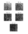
- FIGS. 4 to 10 are scanning electron microscope images of the surface structure of various samples made by the method according to the invention.
- FIG. 11 is a scanning electron microscope micrograph taken from a porous Ti sintered structure
- FIG. 12 is an optical image of a section through a sample showing the microstructure
- FIG. 13 is an image detailing surface structures
- FIGS. 14 and 15 are non-contact surface profilimetry images detailing plan views of the samples.
- FIGS. 16 to 25 are scanning electron microscope micrographs produced prior to multi-layer builds shown in FIGS. 7 and 8 .
- FIG. 26 indicates the metallography and spectra of a typical bond coat structure.
- FIG. 27 shows the effect of line spacing on pore size.
- FIG. 28 a - f are examples of typical waffle structures.
- FIG. 29 is a trabecular bone-type structure constructed from a micro CT scan.
- FIG. 30 shows typical freestanding structures.
- FIG. 31 shows a freestanding structure built using the preferred scanning strategy.
- FIG. 32A illustrates one embodiment of a unit cell of the present invention
- FIG. 32B illustrates an alternate embodiment of a unit cell of the present invention.
- FIG. 32C illustrates a lattice structure formed using a plurality of unit cells illustrated in FIG. 32B ;
- FIG. 33 illustrates lattice structures with and without laser beam compensation formed using the unit cells illustrated in FIG. 32B ;
- FIG. 34A illustrates an alternate embodiment of a unit cell of the present invention
- FIG. 34B illustrates a lattice structure formed using a plurality of unit cells illustrated in FIG. 34A ;
- FIG. 35 illustrates lattice structures formed with and without laser beam compensation
- FIG. 36A illustrates an alternate embodiment of a unit cell of the present invention
- FIG. 36B illustrates a lattice structure formed using a plurality of the unit cells illustrated in FIG. 36A ;
- FIGS. 37A and 37B illustrate actual lattice structures formed using a plurality of unit cells represented in FIG. 36A ;
- FIG. 38A illustrates an additional embodiment of a unit cell of the present invention
- FIG. 38B illustrates a lattice structure created using a plurality of unit cells illustrated in FIG. 38A ;
- FIG. 39A illustrates lattice structures created using unit cells illustrated in FIG. 38A with varying exposure time
- FIG. 39B illustrates lattice structures created using unit cells illustrated in FIG. 32A with varying exposure time
- FIG. 39C illustrates a side view of an embodiment of FIG. 39A ;
- FIG. 39D illustrates a side view of a lattice structure illustrated in FIG. 39B ;
- FIG. 40 is a representation of a lattice structure created using a plurality of the unit cells illustrated in FIG. 38A with random perturbation;
- FIG. 41 illustrates graduation of a solid to a lattice build
- FIG. 42 illustrates a graduation from one lattice density to another
- FIG. 43A illustrates a femoral hip component
- FIG. 43B illustrates an exploded view of FIG. 43A ;
- FIG. 44 illustrates the component of FIG. 43A with a reduced sized femoral attachment
- FIG. 45 illustrates a “jacket” created by the subtraction of the embodiment of FIG. 44 from the embodiment of FIG. 43A ;
- FIG. 46A illustrates one embodiment of a single unit cell for use in an open cellular lattice structure
- FIG. 46B illustrates an open cellular lattice structure
- FIG. 47 illustrates the embodiment illustrated in FIG. 46B merged with the embodiment illustrated in FIG. 44 ;
- FIGS. 48A and 48B illustrate one embodiment of a finished product
- FIGS. 49A-C illustrate an alternate embodiment of a finished product
- FIGS. 50A and 50B illustrate an alternate embodiment of a finished product
- FIGS. 51A-C illustrate an alternate embodiment of a finished product
- FIGS. 52A and 52B illustrate an alternate embodiment of a finished product
- FIG. 53 illustrates an alternate embodiment of a finished product
- FIG. 54 illustrates an alternate embodiment of a finished product
- FIGS. 55A and 55B illustrate an apparatus used in conjunction with the present invention
- FIG. 56 illustrates a zoomed-in view of the embodiment illustrated FIG. 55B ;
- FIG. 57 illustrates a zoomed-in view of the apparatus illustrated in FIG. 55B , further along in the process;
- FIG. 58 illustrates a zoomed-in view of the apparatus illustrated in FIG. 55B , further along in the process;
- FIGS. 59A and 59B illustrate porous surface coatings being applied to a substrate
- FIGS. 60A and 60B illustrate one embodiment of a representation of a finished product
- FIGS. 61A and 61B illustrate one embodiment of a finished product created using the present invention
- FIGS. 62A to 62D illustrate one embodiment of a finished product created using the present invention
- FIG. 63 illustrates a titanium lattice structure with hierarchical surface coating of sintered titanium satellites
- FIGS. 64-71 illustrate the change occurring to the embodiment illustrated in FIG. 63 , while the lattice is exposed to a laser at increasing time periods.
- the present invention relates to a method of forming porous and partially porous metallic structures which are particularly but not exclusively applicable for use in hard or soft tissue interlock structures for medical implants and prosthesis.
- the method makes use of laser technology by employing a variety of scanning strategies.
- Typical metal and metal alloys employed include stainless steel, cobalt chromium alloys, titanium and its alloys, tantalum and niobium, all of which have been used in medical device applications.
- the present invention can be used for such medical device applications where bone and soft tissue interlock with a component is required, or where a controlled structure is required to more closely match the mechanical properties of the device with surrounding tissue. Additionally, the present invention may be employed to enhance the biocompatibility of a porous structure with animal tissue. With these advantages in mind, a structure may be created using specific dimensions required to accommodate a particular patient.
- One particular intention of the present invention is to produce a three-dimensional structure using a laser remelting process, for example, for building structures with or without a solid base or core.
- the three-dimensional structure could be used to provide a porous outer layer to form a bone in-growth structure.
- the porous structure when applied to a core, could be used to form a prosthesis with a defined stiffness to both fulfill the requirement of a modulus match with surrounding tissue and provide interconnected porosity for tissue interlock.
- a further use could be to form an all-porous structure with grade pore size to interact with more than one type of tissue.
- the process can be used to build on a solid base or core with an outer porous surface, the porosity of which is constant or which varies.
- the base or core materials to which the process is applied may be either titanium and its alloys, stainless steel, cobalt chrome alloys, tantalum or niobium as well as any other suitable material.
- the preferred surface coatings are titanium, cobalt chrome and tantalum but both stainless steel and niobium can also be used as well as any other suitable material.
- Fully porous structures may be built from any of the materials tested, with the preferred material being titanium.
- One intention of the present invention is to produce a method which can be exploited on a commercial basis for the production of, for example, bone interlock surfaces on a device although it has many other uses.
- a method of forming a three-dimensional structure includes building the shape by laser melting powdered titanium and titanium alloys, stainless steel, cobalt chrome alloys, tantalum or niobium using a continuous or pulsed laser beam.
- Individual layers of metal are scanned using a laser.
- the laser may be a continuous wave or pulsed laser beam.
- Each layer or portion of a layer is scanned to create a portion of a plurality of predetermined unit cells, as will be described below.
- Successive layers are deposited onto previous layers and also may be scanned.
- the scanning and depositing of successive layers continues the building process of the predetermined unit cells. As disclosed herein, by continuing the building process refers not only to a continuation of a unit cell from a previous layer but also a beginning of a new unit cell as well as the completion of a unit cell.
- the method can be performed so that the structure is porous and if desired, the pores can be interconnecting to provide an interconnected porosity.
- the method can include using a base or core of cobalt chrome alloy, titanium or alloy, stainless steel, niobium and tantalum, on which to build a porous layer of any one of the aforementioned metals and alloys by laser melting using a continuous or pulsed laser beam.
- a base or core of cobalt chrome alloy, titanium or alloy, stainless steel, niobium and tantalum on which to build a porous layer of any one of the aforementioned metals and alloys by laser melting using a continuous or pulsed laser beam.
- a mixture of desired mixed materials may be employed.
- the method can be applied to an existing article made from cobalt chrome, titanium or titanium alloys, stainless steel, tantalum or niobium, such as an orthopedic implant, to produce a porous outer layer from any of the aforementioned metals or alloys to provide a bone in-growth structure.
- a cleaning operation to ensure a contaminant-free surface may be employed prior to the deposition of any powder onto a substrate.
- this process may include a solvent wash followed by a cleaning scan of the laser beam without the presence of particles.
- a coating process may be employed.
- the coating process includes applying a third metal directly to the substrate, which has a higher bond strength to the substrate then does the first layer of powder. This process is particularly useful when the substrate and first powder layer are of different materials.
- the process of coating the substrate may be accomplished using known processes including laser deposition, plasma coating, cold gas dynamic spraying or similar techniques.
- One example of the coating process includes using either niobium or tantalum as an interface between a cobalt chrome alloy substrate and a first layer of titanium powder.
- the present invention can include a laser melting process, which precludes the requirement for subsequent heat treatment of the structure, thereby preserving the initial mechanical properties of the core or base metal.
- the equipment used for the manufacture of such a device could be one of many currently available including the MCP Realiszer, the EOS M270, Trumpf Trumaform 250, the Arcam EBM S12 and the like.
- the laser may also be a custom produced laboratory device.
- the method may be applied to produce an all-porous structure using any of the aforementioned metal or metal alloys.
- Such structures can be used as finished or final products, further processed to form a useful device for bone or soft tissue in-growth, or used to serve some other function such as that of a lattice to carry cells, for example.
- the pore density, pore size and pore size distribution can be controlled from one location on the structure to another. It is important to note that successive powder layers can differ in porosity by varying factors used for laser scanning powder layers. As for example, a first layer of powder is placed and subsequently scanned. Next a second layer of powder is placed and scanned. In order to control porosity the second scan may be angled relative to the first scan. Additionally, the angling of the scanning as compared to previous and post scans may be maneuvered and changed many times during the process of building a porous structure. If a structure was built without alternating the angling of any subsequent scans you would produce a structure having a plurality of walls rather than one with an interconnecting or non-interconnecting porosity.
- the laser melting process includes scanning the laser beam onto the powder in parallel scan lines with a beam overlap i.e., scan spacing, followed by similar additional scans or subsequent scans at 90°.
- the type of scan chosen may depend on the initial layer thickness as well as the web height required.
- Web height refers to the height of a single stage of the porous structure. The web height may be increased by deposited additional layers of powder of a structure and scanning the laser at the same angle of the previous scan.
- the additional scan lines may be at any angle to the first scan, to form a structure with the formation of a defined porosity, which may be regular or random.
- the scan device may be programmed to proceed in a random generated manner to produce an irregular porous construct but with a defined level of porosity.
- the scan can be pre-programmed using digitized images of various structures, such as a trabecular bone, to produce a similar structure. Contrastingly, the scan may be pre-programmed using the inverse of digitized images, such as the inverse of a digitized trabecular bone to produce trabecular shaped voids.
- Many other scanning strategies are possible, such as a waffle scan, all of which can have interconnecting porosity if required.
- the beam overlap or layer overlap may be achieved by rotation of the laser beam, the part being produced, or a combination of both.
- a first method according to the present invention is intended to produce a porous structure for bone in-growth on the outer surface layer of a prosthesis.
- the nature of the material formed as a result of laser melting of powdered beads is principally dependent on the thermal profile involved (heating rate, soaking time, cooling rate); the condition of the raw material (size and size distribution of powder particles); atmospheric conditions (reducing, inert or oxidizing chamber gas) In some instances, the nature of the material formed may be further a result of accurate control of the deposited layer thickness.
- optimum porosity is between approximately 20% and 40%, and aim to mid value with a mean volume percent of voids of about 70%.
- the preferred pore structure is interconnected, with a minimum pore size between about 80 ⁇ m and 100 ⁇ m and a maximum pore size between 80 ⁇ m and 800 ⁇ m.
- the structured thickness for in-growth is 1.4-1.6 mm, but can be larger or smaller depending on the application. As for example, it may be necessary to produce even smaller pore sizes for other types of tissue interaction or specific cellular interaction.
- the first phase of development of the present invention involved an investigation, designed to characterize the material transformation process and to identify the optimum parameters for processing using three substrate materials CoCr and Ti stainless steel alloys, with five powder types Ti, CoCr, Ta and Nb, stainless steel.
- FIG. 1 there is shown the apparatus used to carry out the method which comprises an Nd; YAG industrial laser 1 manufactured by Rofin Sinar Lasers, in Hamburg, Germany, integrated to an RSG1014 analogue galvo-scanning head 2 providing a maximum scan speed of 500 mm/s.
- the laser beam 3 is directed into an atmospherically controlled chamber 4 , which consists of two computer-controlled platforms for powder delivery and part building.
- the powder is delivered from a variable capacity chamber 5 into the chamber 4 and is transported by a roller 6 to a build platform 7 above a variable capacity build chamber 8 .
- the build and delivery system parameters are optimized for an even 100 ⁇ m coating of powder to be deposited for every build layer.
- the metals chosen as surface materials are all difficult to process due to their affinity for oxygen. Cr and Ti are easily oxidized when processed by laser in oxygen-containing atmosphere, their oxide products have high melting points and poor flowability. For this reason, and to prevent the formation of other undesirable phases, the methods were carried out under an Argon inert atmosphere in chamber 8 . Pressure remained at or below atmospheric pressure during the entire application.
- the build chamber 8 illustrated in FIG. 1 and method of layering described above is suitable for test specimens and constructs such as three-dimensional freestanding structures.
- an existing device such as acetabular metal shells, hip and knee femoral components, knee tibial components and other such devices, considerable changes to the powder laying technique would need to be applied.
- Co212-e Cobalt Chrome alloy was used.
- the CoCr was configured into square structures, called coupons. Arrays of CoCr coupons were built onto a stainless steel substrate.
- the Co212-e Cobalt Chrome alloy had a particle size distribution of 90 ⁇ 22 um, i.e., 90% of the particles are less than 22 ⁇ m, the composition of which is shown in the table below.
- An array of nine sample coupons were produced as shown in FIG. 2 , with the process of Table 2, using a maximum laser power of 78 watts (W) and laser scanning speed for each coupon varying between 100-260 mms ⁇ 1 .
- W maximum laser power
- a higher laser power may be employed; however, a higher laser power would also necessitate increasing the speed of the laser scan speed in order to produce the desired melting of the powder layer.
- a simple linear x-direction scan was used on each of the coupons. This allowed the processing parameter, beam overlap, to be used to control the space between successive scan lines. That is, with a 100 ⁇ m laser spot size, an overlap of ⁇ 200% produces a 100 ⁇ m gap between scans.
- the acceptable range for the beam overlap is given at +50% to ⁇ 1200% it should be duly noted that the negative number only refers to the fact the there is a gap as opposed to a beam overlap between successive scans. For instance a beam overlap of zero refers to the fact that successive scans on the same layer of powder border each other. If the beam overlap was 5% then 5% of the first scan is overlapped by the second scan. When computing the Andrew number the absolute value of the beam overlap is used. The complete set of process parameters used is shown in Table 2 below.
- CoCr was the first of four powders to be examined and, therefore, a wide range of process parameters was used. In each case, laser power and the pulse repetition rate were kept constant, i.e., continuous laser pulse, to allow the two remaining parameters to be compared. Layer thickness was maintained at 100 ⁇ m throughout all the experiments described here. Layer thickness can, however, vary between 5 ⁇ m to 2000 ⁇ m.
- the particle size description was 80% ⁇ 75 ⁇ m at a purity of 99.85%. Due to its higher melting temperature compared to that of CoCr (Nb being at about 2468° C., and CoCr being at about 1383° C.), the laser parameters used included a reduced scanning speed range and increased beam overlap providing increased specific energy density at the powder bed. In addition, the pulse repetition rate was varied from 20 kHz to 50 kHz.
- Tantalum used in this study had a particular size distribution of 80% ⁇ 75 ⁇ m with a purity of 99.85%.
- Ta has a melting point of about 2996° C. and was processed using the same laser parameters as Nb. Now confident of the atmospheric inertness, the Ta powder was melted directly onto the CoCr and Ti substrates.
- Bio-medical alloys of Titanium were not readily available in powder form and so pure Ti was chosen.
- the particle size distribution for the Ti powder was 80% ⁇ 45 ⁇ m with a purity of 99.58%.
- the same parameters used for Nb and Ta were also used for the Ti powder.
- Ti has a lower melting point than Ta or Nb, Ti being at about 1660° C., but has a higher thermal conductivity than Ta or Nb. This implies that although the powder should require less energy before melting, the improved heat transfer means a larger portion of the energy is conducted away from the melt pool.
- FIG. 5 is an image of two coupons produced from a CoCr array on Ti alloy substrates. This array was chosen because it best satisfied the requirements of this exercise. The parameters were: laser power of 82 W continuous wave (cw); 25% beam overlap; scanning speed varied from 100 mms ⁇ 1 to 260 mms ⁇ 1 in 20 mm ⁇ 1 increments; the images of the coupons shown here, taken from this array, were produced with scanning speeds of 180 mms ⁇ 1 to 200 mms ⁇ 1 .
- the surface is comprised of fused pathways that develop a network of interconnected pores. This structure continues throughout the layer until the interface is reached.
- the interface is characterized by a patchwork of fusion bonds. These bond sites are responsible for securing the interconnected surface structure to the baseplate.
- the macroscopic structure is covered with unmelted powder particles that appear to be loosely attached.
- FIGS. 6 and 7 are the scanning electron microscope images produced from the Nb and Ta coupons on Ti alloy substrates.
- FIGS. 6( a ) to 6 ( e ) are scanning election microscope images of the surface structure of Nb on Ti alloy substrates, produced with a laser power of 82 W cw, ⁇ 40% beam overlap.
- the scanning speeds used were: 160 mms ⁇ 1 for FIG. 6( a ), 190 mms ⁇ 1 for FIG. 6( b ), 200 mms ⁇ 1 for FIG. 6( c ), 210 mms ⁇ 1 for FIG. 6( d ) and 240 mms ⁇ 1 for FIG. 6( e ), respectively.
- FIGS. 7( a ) to 7 ( c ) are scanning election microscope images of the surface structure of Ta on Ti alloy substrates produced using the same parameters used in the Nb or Ti alloy substrates except: FIG. 7( a ) was produced with a scanning speed of 160 mms ⁇ 1 ; FIG. 7( b )'s speed was 200 mms ⁇ 1 and FIG. 7( c )'s speed was 240 mms ⁇ 1 , respectively.
- An increased beam overlap was used here as Nb and Ta have high melting points, which require a greater energy density.
- the surfaces once again exhibit significant levels of unmelted powder particles and loosely attached resolidified beads that vary in size from a few microns to several hundred microns. All samples were loosely brushed after completion and cleaned in an ultrasonic aqueous bath. It is possible that further cleaning measures may reduce the fraction of loose particles.
- FIGS. 8( a ) to 8 ( e ) are scanning electron microscope images taken from the Ti coupons on the CoCr alloy substrates.
- the laser processing parameters used were the same as those for the Nb and Ta powders, with once again only the speed varying.
- the scanning speed was varied from 160 mms ⁇ 1 ( FIG. 8( a ), 170 mms ⁇ 1 ( FIG. 8( b )), 200 mms ⁇ 1 ( FIG. 8( c )); 230 mms ⁇ 1 ( FIG. 8( d ) to 240 mms ⁇ 1 ( FIG. 8( e )).
- the Ti coupon on CoCr samples, FIGS.
- 8( a ) to 8 ( c )) indicate very high density levels compared to the other examples.
- the line-scans can be clearly seen, with good fusion between individual tracks, almost creating a complete surface layer. The surface begins to break up as the scanning speed is increased.
- FIGS. 9( a ) to 9 ( e ) are scanning electron microscope images of surface structures of Ti on Ti alloy substrates produced with the same parameters used in FIGS. 8( a ) to 8 ( e ), respectively. It is unclear why Ti should wet so well on CoCr substrates. In comparison, Ti on Ti exhibits similar characteristic patterns as with Nb, Ta, and CoCr, specifically, an intricate network of interconnected pores.
- the scanning speed, 160 mms ⁇ 1 and the laser power 72 W cw were kept constant while the beam overlaps; ⁇ 400% in FIGS. 10( a ) and 10 ( b ); ⁇ 500% in FIGS. 10( c ) and 10 ( d ) and ⁇ 600% in FIGS. 10( e ) and 10 ( f ), were varied accordingly.
- Scanning electron microscope micrographs, taken from a porous Ti sintered structure provided by Stryker-Howmedica are shown for reference in FIG. 11 .
- the Ti on Ti substrate was sectioned, hot mounted and polished using a process of 1200 and 2500 grade SiC, 6 ⁇ m diamond paste and 70/30 mixture of OPS and 30% H 2 O 2 .
- the polished sample was then etched with 100 ml H 2 O, 5 ml NH.FHF and 2 cm 3 HCl for 30 seconds to bring out the microstructure. Optical images of this sample in section are shown in FIG. 12 .
- FIG. 13 is an image taken from a non-contact surface profilimentry to show the surface structures obtained when using Ti, CoCr, Ta and Nb on Ti substrates. Values for Ra, Rq and Rb roughness are also shown.
- the key laser parameters varied for forming the three-dimensional metallic porous structures are: (a) Laser scanning speed (v.) in (mms ⁇ 1 ), which controls the rate at which the laser traverses the powder bed; (b) Laser power, P(W), which in conjunction with the laser spot size controls the intensity of the laser beam. The spot size was kept constant throughout the experiment; (c) Frequency, (Hz) or pulse repetition rate. This variable controls the number of laser pulses per second. A lower frequency delivers a higher peak power and vice versa.
- the line width can be related to the laser scanning speed and the laser power to provide a measure of specific density, known as the “Andrew Number”, where:
- a ⁇ ⁇ n P b ⁇ v ⁇ ( J / mm ⁇ - 2 )
- P denotes the power of the laser
- v is the laser scanning speed
- b denotes beam width of the laser.
- the Andrew number is the basis for the calculation of the present invention.
- the Andrew number may also be calculated by substituting the line separation (d) for beam width (b).
- the two methods of calculating the Andrew number will result in different values being obtained.
- line separation (d) as a factor only on track of fused powder is considered, whereas when using the beam width (b) as a factor, two tracks of fused powder are considered as well as the relative influence of one track to the next. For this reason we have chosen to concern our with the Andrew number using scan spacing as a calculating factor. It can thus be appreciated, that the closer these tracks are together the greater the influence they have on one another.
- the laser power may be varied between 5 W and 1000 W. Utilizing lower power may be necessary for small and intricate parts but would be economically inefficient for such coatings and structures described herein. It should be noted that the upper limit of laser power is restricted because of the availability of current laser technology. However, if a laser was produced having a power in excess of 1000 W, the scanning speed of the laser could be increased in order that an acceptable Andrew number is achieved. A spot size having a range between 5 um(fix) to 500 um(fix) is also possible. For the spot size to increase while still maintaining an acceptable Andrew number, either the laser power must be increased or the scanning speed decreased.
- the above formula gives an indication of how the physical parameters can vary the quantity of energy absorbed by the powder bed. That is, if the melted powder has limited cohesion, e.g. insufficient melting, the parameters can be varied to concentrate the energy supply to the powder.
- High Andrew numbers result in reduced pore coverage and an increase in pore size due to the effects of increased melt volume and flow.
- Low Andrew numbers result in low melt volume, high pore density and small pores.
- Current satisfactory Andrew numbers are approximately 0.3 J/mm ⁇ 2 to 8 J/mm ⁇ 2 and are applicable to many alternative laser sources. It is possible to use a higher powered laser with increased scanning speed and obtain an Andrew number within the working range stated above.
- FIGS. 4( a ) to 4 ( c ) are scanning election microscope images of the surface structure of CoCr on stainless steel produced with a laser power of 82 W cw.
- FIG. 4( a ) was produced with a laser scanning speed of 105 mms ⁇ 1
- FIG. 4( b ) was produced with a laser scanning speed of 135 mms ⁇ 1 .
- FIG. 4( a ) was produced with a laser scanning speed of 105 mms ⁇ 1
- FIG. 4( b ) was produced with a laser scanning speed of 135 mms ⁇ 1 .
- FIG. 4( c ) is an image of the same structure in FIG. 4( b ), in section. There is a significant self-ordering within the overall structure. Larger columnar structures are selectively built leaving large regions of unmelted powder. It is worth noting that these pillars are around 300 ⁇ m wide, over 1.6 mm tall and fuse well with the substrate, as seen in FIG. 4( c ). Further analysis shows that the use of a hatched scanning format allows porosity to be more sufficiently controlled to allow the pore size to be directly controlled by the beam overlap.
- Increased fusion may, if required, be obtained by heating the substrate, powder or both prior to scanning.
- Such heating sources are commonly included in standard selective laser sintering/melting machines to permit this operation.
- FIG. 26 shows the metallography of the structures with energy dispersive spectroscopy (EDS) revealing the relative metal positions within the build.
- EDS energy dispersive spectroscopy
- a typical waffle build of titanium on a titanium substrate was constructed as a way of regulating the porous structure. Scanning sequences of 0° 0° 0°, 90° 90° 90°, 45° 45° 45°, 135°, 135°, 135°, of layer thickness 0.1 mm were developed to form a waffle. Three layers of each were necessary to obtain sufficient web thickness in the “z” direction to give a structure of adequate strength. Typical parameters employed were: Laser power was 82 watts, operating frequency between 0 (cw) and 40 KHz, scan speed of between 160 and 240 mm/sec with a beam overlap of ⁇ 700%. FIG. 27 gives an indication of the effect of line spacing and pore size. FIG.
- FIG. 28 ( a ) shows typical examples of the waffle structure.
- the magnification level changes from 10, 20, 30, 70 and 150 times normal viewing as one moves respectively from FIG. (b) to (f).
- FIG. 28 ( a ) more specifically shows Ti powder on a Ti substrate with a controlled porosity by varying line spacing, i.e., beam overlap.
- Trabecular structures of titanium on a titanium substrate were constructed as a way of randomising the porous structures.
- An STL (sterolithography) file representing trabecular structure was produced from a micro CT scan of trabecular bone. This file was sliced and the slice data sent digitally to the scanning control. This allowed the layer-by-layer building of a metallic facsimile to be realised.
- FIG. 29 shows a cross-sectional view of such a construct.
- a method for making lattice-type constructs was referred to in the relevant art.
- a typical example of this type of structure is shown in FIG. 30 .
- the scanning strategy employed to form such a construct was mentioned and such a strategy could be produced within the range of Andrew numbers outlined.
- Table 4 shows an indication of scanning strategies and their relationships to the Andrew number.
- the second and preferred approach uses a continuous scanning strategy whereby the pores are developed by the planar deposition of laser melted powder tracks superimposed over each other. This superimposition combined with the melt flow produces random and pseudorandom porous structures.
- the properties of the final structure, randomness, interconnectivity, mechanical strength and thermal response are controlled by the process parameters employed.
- One set of scanning parameters used was: Scanning sequences of 0° 0° 0°, 90° 90° 90°, 45° 45° 45°, 135°, 135°, 135°, 135°, of layer thickness 0.1 mm were developed to form a waffle. Three layers of each were necessary to obtain sufficient web thickness in the “z” direction. The array of sequences was repeated many times to give a construct of the desired height.
- Laser power was 82 watts, operating frequency between 0 (cw) and 40 KHz, scan speed of between 160 and 240 mm/sec with a beam overlap of ⁇ 700%.
- FIG. 31 shows such a construct.
- Laser cleaning or acid etching technique may be effective. Additionally, a rigorous cleaning protocol to remove all loose powder may entail blowing the porous structure with clean dry compressed gas, followed by a period of ultrasonic agitation in a treatment fluid. Once dried, a laser scan may be used to seal any remaining loose particles.
- a typical example of the use of a bond coat is provided by the combination of titanium on to a cobalt chromium substrate. Tantalum also was an effective bond coat in this example. Note that the bond coat may be applied by laser technology, but other methods are also possible such as gas plasma deposition.
- FIGS. 13( a ) to 13 ( d ) show the surface profile.
- the Surface Data shown in FIGS. 14( a ) and 14 ( b ) and 15 ( a ) and 15 ( b ) show a coded profile of the plan views of the samples.
- FIGS. 16 to 25 are scanning electron microscope (SEM) micrographs of a series of single layer Ti on CoCr and Ti on Ti images that were produced prior to the multi-layer builds shown in FIGS. 8 and 9 respectively and as follows.
- the method according to the present invention can produce surface structures on all powder/baseplate combinations with careful selection of process parameters.
- the process is carried out on flat baseplates that provide for easy powder delivery in successive layers of around 100 ⁇ m thickness. Control of powder layer thickness is very important if consistent surface properties are required.
- the application of this technology can also be applied to curved surfaces such as those found in modern prosthetic devices; with refinements being made to the powder layer technique.
- the structures have all received ultrasonic and aqueous cleaning.
- the resultant porous surfaces produced by the Direct Laser Remelting process exhibit small particulates that are scattered throughout the structure. It is unclear at this stage whether these particulates are bonded to the surface or loosely attached but there are means to remove the particulates if required.
- the Direct Laser Remelting process has the ability to produce porous structures that are suitable for bone in-growth applications.
- the powdered surfaces have undergone considerable thermal cycling culminating in rapid cooling rates that have produced very fine dendritic structures (e.g. FIGS. 13( a ) to 13 ( d )).
- the Direct Laser Remelting process can produce effective bone in-growth surfaces and the manufacturing costs are reasonable.
- the object has been to provide a porous structure on a base but the present invention can also be used to provide a non-porous structure on such a base to form a three-dimensional structure.
- the same techniques can be utilized for the materials concerned but the laser processing parameters can be appropriately selected so that a substantially solid non-porous structure is achieved.
- a technique can be used to deposit the powder onto a suitable carrier, for example a mold, and to carry out the process without the use of a base so that a three-dimensional structure is achieved which can be either porous, as described above, or non-porous if required.
- the porosity of successive layers of powder can be varied by either creating a specific type of unit cell or manipulating various dimensions of a given unit cell.
- optimum porosity is between approximately 20% and 40%, and aim to mid value with a mean volume percent of voids of about 70%.
- the preferred pore structure is interconnected, with a minimum pore size between about 80 ⁇ m and 100 ⁇ m and a maximum pore size between 80 ⁇ m and 800 ⁇ m.
- the structured thickness for in-growth is 1.4-1.6 mm, but can be larger or smaller depending on the application.
- porous structures are built in the form of a plurality of unit cells.
- Many designs of unit cells are possible to give the shape, type, degree, and size of porosity required.
- Such unit cell designs can be dodecahedral, octahedral, diamond, as well as many other various shapes.
- the unit cells of the present invention may be configured to have irregular shapes where various sides and dimensions have little if any repeating sequences.
- the unit cells can be configured to constructs that closely mimic the structure of trabecular bone for instance.
- Unit cells can be space filling, all the space within a three-dimensional object is filled with cells, or interconnected where there may be some space left between cells but the cells are connected together by their edges.
- the cells can be distributed within the construct a number of ways. Firstly, they may be made into a block within a computer automated design system where the dimensions correspond to the extent of the solid geometry. This block can then be intersected with the geometry representing the component to produce a porous cellular representation of the geometry. Secondly, the cells may be deformed so as to drape over an object thus allowing the cells to follow the surface of the geometry. Thirdly, the cells can be populated through the geometry following the contours of any selected surface.
- the unit cell can be open or complete at the surface of the construct to produce a desired effect.
- open cells with truncated lattice struts produce a surface with a porosity and impart the surface with some degree of barb.
- Modifying the lattice strut dimensions can control the mechanical strength of the unit cell. This modification can be in a number of key areas.
- the lattice strut can be adjusted by careful selection of build parameters or specifically by changing the design of the cross-section of each strut.
- the density of the lattice can similarly be adjusted by modification of the density of the unit cells as can the extent and shape of porosity or a combination thereof.
- the overall design of the unit cell will also have a significant effect of the structural performance of the lattice. For instance, dodecahedral unit cells have a different mechanical performance when compared to a tetrahedral (diamond) structure.
- each point 10, 12, 14, and 16 is the same distance from the neighboring point.
- This structure is analogous to the arrangements of the carbon atoms in diamond.
- Each carbon atom in the diamond is surrounded by four nearest neighbors. They are connected together by bonds that separate them by a distance of 1.5445 angstroms. The angles between these bonds are 109.5 degrees. As a result, the central atom and its neighbors form a tetrahedron. This geometry as in the case discussed herein may then be scaled to appropriate value for the pore construct required.
- the two key parameters used to define the relations regarding height, surface area, space height, volume of tetrahedron, and the dihedral angle of a tetrahedron are the strand length of the tetrahedron and, i.e., the diameter or height and width, cross section area of the strand i.e., strut. These two parameters control the pore size and porosity of the structure.
- the parameter editor and relation editor within a typical CAD system can be used to control these parameters. Hence, by changing the parameters one can change the fundamental properties of the porous structure.
- the diamond structure may have a circular cross-section strands or square cross-section strands. Although only two strand cross-sections are illustrated, strands having various cross-sections are possible. Further, this is true with most of the designs for the unit cell.
- FIG. 33 illustrates a view of a diamond lattice structure with and without laser beam compensation.
- Laser beam compensation essentially allows the diameter of the beam to be taken into account. Without it the constructed geometry is one beam diameter too wide as the beam traces out the contour of the particular section being grown. When laser beam compensation is utilized, the contour is offset half a beam diameter all around the constructed geometry which is represented in the CAD file.
- the parameters employed to create the lattices of FIG. 33 include a laser power of 90.5 watts with an exposure time of 1,000 ⁇ sec from a point distance of 90 ⁇ m. Table 1 illustrates various other examples of parameters that may be used to create various unit cells.
- the porous structure can also be created using a unit cell in the shape of a dodecahedron.
- the regular dodecahedron is a platonic solid composed of 20 polyhydron vertices, 30 polyhydron edges, and 12 pentagonal faces.
- This polyhydron is one of an order of five regular polyhedra, that is, they each represent the regular division of 3-dimensional space, equilaterally and equiangularly.
- This basic unit cell for a decahedron mesh can be built up in a CAD package using the following calculations and procedure.
- the dodecahedron has twelve regular pentagonal faces, twenty vertices, and thirty edges. These faces meet at each vertex.
- the calculations for a side length of a dodecahedron are given by simple trigonometry calculations and are known by those in the art.
- a sweep feature is first used to model the dodecahedron structure by driving a profile along a trajectory curve.
- the trajectory curves are constructed from datum points corresponding to the vertices of the dodecahedron connected by datum curves.
- the type of profile remains constant along the sweep producing the model shown in FIG. 34A .
- the size and shape of the profile can be designed to suit the particular application and the required strut diameter.
- the cell can be instanced to produce a regular lattice as shown in FIG. 34B .
- meshes are produced by simple offsetting of the unit cell and allowing some of the struts to overlap. This method of overlapping may be used with the alternate shapes of the unit cell.
- FIG. 35 shows a view of a dodecahedron (with and without laser beam compensation, from left to right) structure using selective laser melting process parameters.
- the lattices of FIG. 35 were created using the following parameters; a laser power of 90.5 watts, exposure of the powder for 1,000 ⁇ sec and a point distance of 90 ⁇ m.
- the unit cell of the present invention may also be constructed in the shape of a truncated octahedron.
- a truncated octahedron has eight regular hexagonal faces, six regular square faces, twenty-four vertices, and thirty-six edges. A square and two hexagons meet at each vertex.
- the octahedron When the octahedron is truncated, it creates a square face replacing the vertex, and changes the triangular face to a hexagonal face.
- This solid contains six square faces and eight hexagonal faces. The square faces replace the vertices and thus this leads to the formation of the hexagonal faces.
- various dimensions such as the octahedron height, octahedron volume, octahedron surface area, octahedron dihydral angle, and truncated octahedron volume, truncated octahedron height, truncated octahedron area, truncated octahedron volume, truncated octahedron dihydral angle can be determined by simple trigonometry and are known by those skilled in the art.
- a CAD model of the truncated octahedron is constructed using the sweep feature and calculations and dimensions are incorporated using basic trigonometry.
- Two tessellate the unit cell the unit cell is first reoriented to enable easy tessellation and to reduce the number of horizontal struts in the model.
- the model can be modified to remove all of the horizontal struts as shown in FIG. 38A .
- the modified structure is reproduced in order to save file size in the Steriolithography (“STL”) format of the program.
- STL Steriolithography
- the parameter chosen includes a laser power of 90.5 watts, an exposure of 1000 ⁇ sec with a point distance of 90 ⁇ m.
- FIG. 38B illustrates a lattice structure formed using a plurality of individual truncated octahedron. As discussed earlier, the removal of various struts can create a barb effect on the exterior surface of the lattice structure.
- FIGS. 39A-D it is possible to reduce the size of the unit cell geometry. Also as shown, it is possible to manufacture open cell structures with unit cell sizes below 1 millimeter.
- FIG. 39A illustrates truncated octahedron structures manufactured using the laser melting process. All the structures were created using a laser power of 90.5 W, and a point distance of 90 ⁇ m; however, from left to right, the exposure time was varied from 500 ⁇ sec and 100 ⁇ sec.
- FIG. 39B illustrates similar structures and parameters as used with FIG. 39A , however, the unit cell used to create the lattice is diamond.
- FIGS. 39C and 39D illustrate a side view of the truncated octahedron structure of FIG. 39A and the diamond structure of FIG. 39B , respectively. Table 2 includes various manufacturing parameters used to construct various unit cell structure.
- Random representative geometries may be made from the current regular unit cells by applying a random X, Y, Z perturbation to the vertices of the unit cells.
- a random X, Y, Z perturbation to the vertices of the unit cells.
- FIG. 40 One such example can be seen in FIG. 40 .
- various freestanding constructs can be generated. In a typical manufacturing procedure for the production of a construct, in this case a femoral hip component, the laser melting of appropriate metallic powders is employed. Table 3 listed below, includes various examples of equipment and material used in the construct, as well as typical software utilized.
- an STL file of hip component 50 is loaded into an engineering design package such as Magics, as shown in FIG. 43A .
- the femoral attachment 51 may then be segmented from the body 52 of the construct.
- the femoral attachment 51 may then be scaled down to 80% of its original size and reattached to the body 52 of the implant 50 as shown in FIG. 44 .
- the selection of the amount of scaling or indeed the design of the core allows for the production of the required structural properties of the stem.
- the core may either be scaled down even more or less to meet the required needs of the implant.
- a Boolean operation may next be performed in Magics to subtract the reduced femoral attachment from the original. This creates a “jacket” 56 i.e., mold to be used as the interconnecting porous construct as shown in FIG. 45 .
- Jacket 56 is processed via a bespoke application that populates STL shapes with repeating open cellular lattice structures (OCLS).
- the OCLS used in this instance is a repeating unit cell of size 1.25 millimeters and strand diameter 200 ⁇ m.
- FIG. 46A illustrates a representation of a single unit cell of the OCLS which will be used to populate jacket 56 .
- the OCLS “jacket” 56 as shown in FIG. 46B will act as the porous surface coating of the femoral attachment 50 .
- the OCLS is sliced using a bespoke program written in the Python programming language with a layer thickness of 50 ⁇ m.
- the main body of the construct is then loaded into Fusco, a user interface for the MCP realizer.
- the file is then prepared for manufacture by slicing the file with a 50 ⁇ m layer thickness and applying the hatching necessary for building solid constructs.
- the component and OCLS femoral coating are then merged as shown in FIG. 47 .
- the component may then be built on the SLM system as shown in FIG. 48A with typical process parameters being shown in table 4 below.
- FIG. 48A the present invention may also be used to construct additional elements.
- other elements include an acetabular cup component illustrated in FIGS. 49A-49C , augments from knee and hip surgery, FIGS. 50A and 50B , spinal components FIGS. 51A-51C , maxillofacial reconstruction FIGS. 52A and 52B , part of a special nature, FIG. 53 , and other additional irregular shapes such as that shown in FIG. 54 .
- FIGS. 49A-49C augments from knee and hip surgery
- FIGS. 50A and 50B spinal components
- FIGS. 51A-51C maxillofacial reconstruction
- FIG. 53 part of a special nature
- FIG. 54 the list of illustrative components above is only an example of various constructs which may be composed using the method as disclosed herein and should be thought of as being inclusive as opposed to exclusive.
- an existing product may be coated with various metal layers and then scanned with a laser in order to produce a finished product.
- the present invention i.e., SLM requires the design of a special powder lay system.
- FIGS. 55A-59B One such example was conducted and is shown in FIGS. 55A-59B .
- a convex surface was created by using build apparatus 60 as shown in FIGS. 55A-58 .
- Build apparatus 60 includes a rotating piston 62 and a cylinder onto which the convex surface 64 to be coated was mounted. As the component rotates on the cylinder, it was made to drop in the Z-direction using platform 66 within the SLM machine.
- Powder 71 was deposited onto the side of the component using a powder hopper 68 and a wiper device 70 that runs up against the surface of the component.
- a laser (not shown in the figures) in conjunction with a computer and various programming packages, including those already discussed, were used to apply a laser beam to the powder in a predetermined manner.
- the powder was deposited by hopper 68 and wiped to the correct height by wiper device 70 .
- a full layer of metal powder was deposited by rotation of the cylinder through a full 360 degrees.
- the synthesis of the laser melting process and the layer production process requires that only a fraction of the circumference is layered and melted at any one time.
- FIGS. 55A-58 illustrate the sequence of operations with a final coated sample being shown in FIGS. 59A and 59B .
- the lattice structure was built 3 mm thick and disposed against a 70 mm diameter steel hemisphere.
- FIGS. 60A-B are CAD illustrations of the final assembly of a product component.
- the process can be parallelized by addition of many pistons and cylinder pairs around a central laser beam.
- Optimal laser alignment to the surface can be achieved by a number of methods, including inclining the piston and cylinder pairs so the powder surface and the part surface are correctly aligned normal to the laser beam. Typical operating parameters are shown in Table 5 below.
- the laser produced porous structure system may be used to manufacture a porous shell which then can be inserted over a substrate and sintered in order to fix permanently to the same.
- Some examples include the preparation of an acetabular cup component, a tibia knee insert component, and a femoral insert as well as many additional products.
- the outer profile of an acetabular component which serves as an inner profile of a “cap” to insure that an accurate fit is achieved when the cap is set on the substrate (acetabular shell).
- the cup is built to a thickness of 1.5 millimeters for example using a diamond configured construct to develop the interconnecting porosity.
- the metal powder used in one example is stainless steel.
- Table 6 The processing parameters are shown in Table 6 listed below:
- FIG. 62A illustrates a finished product manufactured by SLM.
- a rim 70 on the inner surface of the cap that interfaces with the groove 72 on the outer surface of the acetabular cup component 68 may be included.
- This mechanism acts a simple lock and gives both security and extra rigidity during the sintering process. Additional modifications may be utilized to improve closeness of the fit and stability. For instance, the introduction of “snap-fits” which are apparent in everyday plastic components may be employed to provide a more reliable attachment mechanism between the two elements.
- Typical pads or center pads for both the femoral and tibial knee components can be produced by the SLM process and dropped or snapped fit into place to the components and then sintered to attach firmly to the underlying substrate. As previously stated, this technique can apply to other components where a porous outer surface is required to interface with either soft or hard tissue.
- a further improvement in the mechanical and microstructural properties of the porous construct may be achieved by either conventional sintering under vacuum or inert atmosphere and/or hot isostatic pressing using temperature regimes known in the state of the art. As the constructs possess high density properties throughout their strands minimal degradation in the structure of the construct is apparent.
- the appearance of the porous construct can be changed by the alteration of the processing conditions or by the introduction of an acid etch process.
- the laser power or laser residence time may be reduced or a combination of both which creates struts of the porous construct having a coating with layers of unmelted metal particles firmly adhered to the strut surfaces.
- This has the effect of producing additional porous features that offer a new dimension to the overall porous structure of the construct.
- Such features are able to interact with cells in a different manner than the microstructure imparted by the lattice construct and provide extra benefits.
- a typical example of such construct with this satellite appearance as depicted in FIG. 63 together with the processing parameters is employed.
- the structure illustrated in FIG. 63 was created using a laser power of 44.2 W and exposure time of 400 ⁇ sec.
- the metal layer thickness was 50 ⁇ m.
- the acid may consist of a mixture of 10 milliliters of hydrogenfloride (HF), 5 milliliters of nitric acid (HNO 3 ) and 85 milliliters of H 2 0. the HF and HNO 3 were respectively 48% and 69% concentrated.
- FIGS. 64 and 71 show the effects of such an acid's etch with respect to time with the relevant conditions being noted. It can be seen clearly that the solids are moved to give a pure melted lattice construct. It is also clearly evident that the overall openness within the lattice is increased by the removal of the satellites.
- this method can, therefore, be used to produce an article from the metals referred to which can be created to a desired shape and which may or may not require subsequent machining. Yet again, such an article can be produced so that it has a graded porosity of, e.g., non-porous through various degrees of porosity to the outer surface layer.
- Such articles could be surgical prostheses, parts or any other article to which this method of production would be advantageous.
Abstract
Description
| TABLE 1 |
| Composition of Co212−e CoCr alloy |
| Element | Cr | Mo | Si | Fe | Mn | Ni | N | C | Co |
| Wt % | 27.1 | 5.9 | 0.84 | 0.55 | 0.21 | 0.20 | 0.16 | 0.050 | Balance |
| TABLE 2 |
| Process parameters |
| Power | Layer | Beam | Scanning | Overlap | ||
| Watts | Thickness | Diameter | Speed | Atmos- | No. of | (% of line |
| (W) | ( μm) | ( μm) | (mms−1) | phere | Layers | width) |
| 78 | 100 | 100 | 100-260 | No | 16 | 25, 50, −500 |
Where P denotes the power of the laser, v is the laser scanning speed and b denotes beam width of the laser. The Andrew number is the basis for the calculation of the present invention. The Andrew number may also be calculated by substituting the line separation (d) for beam width (b). The two methods of calculating the Andrew number will result in different values being obtained. When using line separation (d) as a factor only on track of fused powder is considered, whereas when using the beam width (b) as a factor, two tracks of fused powder are considered as well as the relative influence of one track to the next. For this reason we have chosen to concern ourselves with the Andrew number using scan spacing as a calculating factor. It can thus be appreciated, that the closer these tracks are together the greater the influence they have on one another.
-
- (i) Initial cleaning scan with a scan speed between 60 to 300 mm/sec, laser power 82 watts, frequency of 30 KHz, and a 50% beam overlap.
- (ii) Niobium or tantalum deposition with three layers of 50 μm using a laser power of 82 watts,
frequency 30 to 40 KHz, with a laser speed of between 160 to 300 mm/sec. The beam overlap was low at 50% to give good coverage. - (iii) A build of porous titanium was constructed using a laser power of 82 watts, frequency between 0 (cw) and 40 KHz, scanning speed of between 160 and 240 mm/sec, and beam overlap of −700%.
The strengths of the constructs are indicated in Table 3 with a comparison of the values obtained without the base coat.
| TABLE 3 | |||
| MAXIMUM | TENSILE | ||
| LOAD | STRENGTH | ||
| SPECIMEN | (kN) | (MPa) | FAILURE MODE |
| Ti on CoCr | 2.5 | 5 | Interface |
| Ti on CoCr | 3.1 | 6.2 | Interface |
| 1 (Nb on | 13.0 | 26.18 | 65% adhesive, 35% bond |
| Co—Cr) | interface | ||
| 4 (Ti on | 7 .76 | 15.62 | Mostly bond coat |
| on Co—Cr) | interface | ||
| 5 (Ti on Nb | 9.24 | 18.53 | 20% adhesive, 40% bond |
| on Co—Cr) | coat, 40% porous Ti | ||
| 6 (Ti on Ta | 11.58 | 23.33 | Mostly adhesive with |
| on Co—Cr) | discrete webbing | ||
| weakness | |||
| 8 (Ta on | 13.93 | 27.92 | 60% adhesive, 40% bond |
| Co—Cr) | interface | ||
| 9 (Ti on Ta | 6.76 | 13.62 | 100% bond interface |
| on Co—Cr) | |||
| TABLE 4 | |||||
| RELATIVE | |||||
| BUILD | |||||
| SCAN | PARAMETER | LAYER | PLATFORM | ||
| LAYER | STRATEGY | SET | THICKNESS | POSITION | ADDITIONAL |
| Ti on Ta on CoCr Experimental Procedure. |
| Initial |
| Zero |
| 0 | |||||
| Distance | |||||
| Between | |||||
| Roller & | |||||
| | |||||
| Platform | |||||
| 0 | 1st |
50 μm | −50 μm | ||
| thickness | |||||
| set using | |||||
| feeler | |||||
| gauges but | |||||
| powder not | |||||
| laid in | |||||
| preparation | |||||
| for | |||||
| cleaning | |||||
| scan with | |||||
| no powder. | |||||
| 1 | 50% Beam | P = 82 W | Initial | ||
| Overlap | Qs = 30 kHz | Cleaning | |||
| v = 60 mm/s | Scan (no | ||||
| An = | powder) | ||||
| 27.333 J/mm2 | |||||
| Circular | P = 82 W | Powder | |||
| profile. | Qs = 40 kHz | laid as | |||
| 5 | V = | usual | |||
| concentric | 160 mm/s | ||||
| circles, | An = | ||||
| 0.1 mm | 5.125 J/mm2 | ||||
| offset to | |||||
| negate | |||||
| effects of | |||||
| ‘First | |||||
| Pulse’ | |||||
| 50% Beam | P = 82 W | Scanned on | |||
| Overlap | Qs = 30 kHz | same | |||
| v = | |
||||
| 300 mm/s | layer as | ||||
| An = | previous | ||||
| 5.467 J/mm2 | profile | ||||
| scan. | |||||
| 2 | Circular | P = 82 |
50 μm | −100 μm | Powder |
| profile. | Qs = 40 kHz | laid as | |||
| 5 | V = | usual | |||
| concentric | 160 mm/s | ||||
| circles, | An = | ||||
| 0.1 mm | 5.125 J/mm2 | ||||
| offset to | |||||
| negate | |||||
| effects of | |||||
| ‘First | |||||
| Pulse’ | |||||
| 50% Beam | P = 82 W | Scanned on | |||
| Overlap | Qs = 30 kHz | same | |||
| v = | |
||||
| 300 mm/s | layer as | ||||
| An = | previous | ||||
| 5.467 J/mm2 | profile | ||||
| scan. | |||||
| 3 | Circular | P = 82 |
50 μm | −150 μm | Powder |
| profile. | Qs = 40 kHz | laid as | |||
| 5 | V = | usual | |||
| concentric | 160 mm/s | ||||
| circles, | An = | ||||
| 0.1 mm | 5.125 J/mm2 | ||||
| offset to | |||||
| negate | |||||
| effects of | |||||
| ‘First | |||||
| Pulse’ | |||||
| 50% Beam | P = 82 W | Scanned on | |||
| Overlap | Qs = 30 kHz | same | |||
| v = | |
||||
| 300 mm/s | layer as | ||||
| An = | previous | ||||
| 5.467 J/mm2 | profile | ||||
| scan. |
| |
| 0 | 1st layer | −150 μm | |||
| thickness | |||||
| set using | |||||
| feeler | |||||
| gauges but | |||||
| powder not | |||||
| laid in | |||||
| preparation | |||||
| for cleaning | |||||
| scan with no | |||||
| powder. | |||||
| 1 | 50% Beam | P = 82 |
50 μm | −200 μm | Cleaning |
| Overlap | Qs = | Scan (No | |||
| 30 kHz | powder. | ||||
| v = | |||||
| 60 mm/s | |||||
| An = | |||||
| 27.3 J/mm2 | |||||
| Circular | P = 82 W | Powder | |||
| profile. | Qs = | spread but | |||
| 5 concentric | 40 kHz | build | |||
| circles, | V = | platform | |||
| 0.1 mm offset | 160 mm/s | not | |||
| to negate | An = | lowered. | |||
| effects of | 5.125 J/mm2 | ||||
| ‘First | |||||
| Pulse’ | |||||
| 50% Beam | P = 82 W | Scanned on | |||
| Overlap | Qs = | same | |||
| 30 kHz | powder | ||||
| v = | layer as | ||||
| 300 mm/s | previous | ||||
| An = | profile | ||||
| 5.467/mm2 | scan. | ||||
| 2 | Circular | P = 82 |
100 μm | −300 μm | Powder |
| profile. | Qs = | laid as | |||
| 5 concentric | 40 kHz | usual | |||
| circles, | V = | ||||
| 0.1 mm offset | 160 mm/s | ||||
| to negate | An = | ||||
| effects of | 5.125 J/mm2 | ||||
| ‘First | |||||
| Pulse’ | |||||
| 25% Beam | P = 82 W | Scanned on | |||
| Overlap | Qs = | same | |||
| 30 kHz | powder | ||||
| v = | layer as | ||||
| 300 mm/s | previous | ||||
| An = | profile | ||||
| 3.644 J/mm2 | scan. | ||||
| 3 | Circular | P = 82 |
100 μm | −400 μm | Powder |
| profile. | Qs = | laid as | |||
| 5 concentric | 40 kHz | usual | |||
| circles, | V = | ||||
| 0.1 mm offset | 160 mm/s | ||||
| to negate | An = | ||||
| effects of | 5.125 J/mm2 | ||||
| ‘First | |||||
| Pulse’ | |||||
| 0% Beam | P = 82 W | Scanned on | |||
| Overlap | Qs = | same | |||
| 30 kHz | powder | ||||
| v = | layer as | ||||
| 300 mm/s | previous | ||||
| An = | profile | ||||
| 2.733 J/mm2 | scan. | ||||
| 4 | Waffle 0 and | P = 82 W | 75 μm | −475 μm | Powder |
| 90° | Qs = 0 Hz | laid as | |||
| 700pm | (cw) | usual | |||
| linespacing | v = | ||||
| (−600% Beam | 240 mm/s | ||||
| overlap) | An = | ||||
| 0.488 J/mm2 | |||||
| 5 | Waffle 0 and | P = 82 W | 75 μm | −550 μm | Powder |
| 90° | Qs = 0 Hz | laid as | |||
| 700 μm | (cw) | usual | |||
| linespacing | v = | ||||
| (−600% Beam | 240 mm/s | ||||
| overlap) | An = | ||||
| 0.488 J/mm2 | |||||
| 6 | Waffle 0 and | P = 82 W | 75 μm | −625 μm | Powder |
| 90° | Qs = 0 Hz | laid as | |||
| 700 μm | (cw) | usual | |||
| linespacing | v = | ||||
| (−600% Beam | 240 mm/s | ||||
| overlap) | An = | ||||
| 0.488 J/mm2 | |||||
| 7 | Waffle 45 | P = 82 W | 75 μm | −700 μm | Powder |
| and 135° | Qs = 0 Hz | laid as | |||
| 700 μm | (cw) | usual | |||
| linespacing | v = | ||||
| (−600% Beam | 240 mm/s | ||||
| overlap) | An = | ||||
| 0.488 J/mm2 | |||||
| 8 | Waffle 45 | P = 82 W | 75 μm | −775 μm | Powder |
| and 135° | Qs = 0 Hz | laid as | |||
| 700 μm | (cw) | usual | |||
| linespacing | v = | ||||
| (−600% Beam | 240 mm/s | ||||
| overlap) | An = | ||||
| 0.488 J/mm2 | |||||
| 9 | Waffle 45 | P = 82 W | 75 μm | −850 μm | Powder |
| and 135° | Qs = 0 Hz | laid as | |||
| 700 μm | (cw) | usual | |||
| linespacing | v = | ||||
| (−600% Beam | 240 mm/s | ||||
| overlap) | An = | ||||
| 0.488 J/mm2 |
| Ti on Ti Experimental Procedure. |
| Initial |
| Zero |
| 0 | |||||
| Distance | |||||
| Between | |||||
| Roller & | |||||
| | |||||
| Platform | |||||
| 0 | 1st |
50 μm | −50 μm | ||
| thickness | |||||
| set using | |||||
| feeler | |||||
| gauges but | |||||
| powder not | |||||
| laid in | |||||
| preparation | |||||
| for | |||||
| cleaning | |||||
| scan with | |||||
| no powder. | |||||
| 50% Beam | P = 82 W | Initial | |||
| Overlap | Qs = 30 kHz | Cleaning | |||
| v = 60 mm/s | Scan (no | ||||
| An = | powder) | ||||
| 27.333 J/ |
|||||
| 1 | Circular | P = 82 W | Powder | ||
| profile. | Qs = 40 kHz | laid as | |||
| 5 | V = | usual | |||
| concentric | 160 mm/s | ||||
| circles, | An = | ||||
| 0.1 mm | 5.125 J/mm2 | ||||
| offset to | |||||
| negate | |||||
| effects of | |||||
| ‘First | |||||
| Pulse’ | |||||
| 50% Beam | P = 82 W | Scanned on | |||
| Overlap | Qs = 30 kHz | same | |||
| v = | |
||||
| 300 mm/s | layer as | ||||
| An = | previous | ||||
| 5.467 J/mm2 | profile | ||||
| scan. | |||||
| 2 | Circular | P = 82 |
50 μm | −100 μm | Powder |
| profile. | Qs = 40 kHz | laid as | |||
| 5 | V = | usual | |||
| concentric | 160 mm/s | ||||
| circles, | An = | ||||
| 0.1 mm | 5.125 J/mm2 | ||||
| offset to | |||||
| negate | |||||
| effects of | |||||
| ‘First | |||||
| Pulse’ | |||||
| 50% Beam | P = 82 W | Scanned on | |||
| Overlap | Qs = 30 kHz | same | |||
| v = | |
||||
| 300 mm/s | layer as | ||||
| An = | previous | ||||
| 5.467 J/mm2 | profile | ||||
| scan. | |||||
| 3 | Circular | P = 82 |
50 μm | −150 μm | Powder |
| profile. | Qs = 40 kHz | laid as | |||
| 5 | V = | usual | |||
| concentric | 160 mm/s | ||||
| circles, | An = | ||||
| 0.1 mm | 5.125 J/mm2 | ||||
| offset to | |||||
| negate | |||||
| effects of | |||||
| ‘First | |||||
| Pulse’ | |||||
| 50% Beam | P = 82 W | Scanned on | |||
| Overlap | Qs = 30 kHz | same | |||
| v = | |
||||
| 300 mm/s | layer as | ||||
| An = | previous | ||||
| 5.467 J/mm2 | profile | ||||
| scan. |
| |
| 1 | Circular | P = 82 |
100 μm | −250 μm | Powder |
| profile. | Qs = 40 kHz | laid as | |||
| 5 concentric | V = | usual | |||
| circles, | 160 mm/s | ||||
| 0.1 mm offset | An = | ||||
| to negate | 5.125 J/mm2 | ||||
| effects of | |||||
| ‘First | |||||
| Pulse’ | |||||
| 50% Beam | P = 82 W | Scanned on | |||
| Overlap | Qs = 30 kHz | same | |||
| v = | |
||||
| 300 mm/s | layer as | ||||
| An = | previous | ||||
| 5.467 J/mm2 | profile | ||||
| scan | |||||
| 2 | Circular | P = 82 |
100 μm | −350 μm | Powder |
| profile. | Qs = 40 kHz | laid as | |||
| 5 concentric | V = | usual | |||
| circles, | 160 mm/s | ||||
| 0.1 mm offset | An = | ||||
| to negate | 5.125 J/mm2 | ||||
| effects of | |||||
| ‘First | |||||
| Pulse’ | |||||
| 25% Beam | P = 82 W | Scanned on | |||
| Overlap | Qs = 30 kHz | same | |||
| v = | |
||||
| 300 mm/s | layer as | ||||
| An = | previous | ||||
| 3.644 J/mm2 | profile | ||||
| scan. | |||||
| 3 | Circular | P = 82 |
100 μm | −450 μm | Powder |
| profile. | Qs = 40 kHz | laid as | |||
| 5 concentric | V = | usual | |||
| circles, | 160 mm/s | ||||
| 0.1 mm offset | An = | ||||
| to negate | 5.125 J/mm2 | ||||
| effects of | |||||
| ‘First | |||||
| Pulse’ | |||||
| 0% Beam | P = 82 W | Scanned on | |||
| Overlap | Qs = 30 kHz | same | |||
| v = | powder | ||||
| 300 mm/s | layer as | ||||
| An = | previous | ||||
| 2.733 J/mm2 | profile | ||||
| scan. | |||||
| 4 | Waffle 0 and | P = 82 W | 75 μm | −525 μm | Powder |
| 90° | Qs = 0 Hz | laid as | |||
| 700 μm | (cw) | usual | |||
| linespacing | v = | ||||
| (−600% Beam | 240 mm/s | ||||
| overlap) | An = | ||||
| 0.488 J/mm2 | |||||
| 5 | Waffle 0 and | P = 82 W | 75 μm | −600 μm | Powder |
| 90° | Qs = 0 Hz | laid as | |||
| 700 μm | (cw) | usual | |||
| linespacing | v = | ||||
| (−600% Beam | 240 mm/s | ||||
| overlap) | An = | ||||
| 0.488 J/mm2 | |||||
| 6 | Waffle 0 and | P = 82 W | 75 μm | −675 μm | Powder |
| 90° | Qs = 0 Hz | laid as | |||
| 700 μm | (cw) | usual | |||
| linespacing | v = | ||||
| (600% Beam | 240 mm/s | ||||
| overlap) | An = | ||||
| 0.488 J/mm2 | |||||
| 7 | Waffle 45 | P = 82 W | 75 μm | −750 μm | Powder |
| and 135° | Qs = 0 Hz | laid as | |||
| 700 μm | (cw) | usual | |||
| linespacing | v = | ||||
| (−600% Beam | 240 mm/s | ||||
| overlap) | An = | ||||
| 0.488 J/mm2 | |||||
| 8 | Waffle 45 | P = 82 W | 75 μm | −825 μm | Powder |
| and 135° | Qs = 0 Hz | laid as | |||
| 700 μm | (cw) | usual | |||
| linespacing | v = | ||||
| (−600% Beam | 240 mm/s | ||||
| overlap) | An = | ||||
| 0.488 J/mm2 | |||||
| 9 | Waffle 45 | P = 82 W | 75 μm | −900 μm | Powder |
| and 135° | Qs = 0 Hz | laid as | |||
| 700 μm | (cw) | usual | |||
| linespacing | v = | ||||
| (−600% Beam | 240 mm/s | ||||
| overlap) | An = | ||||
| 0.488 J/mm2 | |||||
| TABLE 1 | |||||
| edge | laser | point | |||
| length | diameter | power | exposure | distance | |
| Part build on SLM | μm | μm | Watts | μsec | μm |
| Diamond Structure | 2000 | 200 | 90.5 | 1000 | 90 |
| Diamond Structure | 2000 | 200 | 90.5 | 1000 | 90 |
| with compensation | |||||
| Dodecahedron | 1500 | 200 | 68.3 | 1000 | 90 |
| Structure | |||||
| Dodecahedron | 1500 | 200 | 68.3 | 1000 | 90 |
| Structure with | |||||
| compensation | |||||
| Modified | 1500 | 200 | 90.5 | 1000 | 90 |
| Truncated | |||||
| Octahedron | |||||
| TABLE 2 | ||||||
| Strand | Length | Width | Laser | Point | ||
| Part build | length | of strand | of strand | Power | Exposure | distance |
| on SLM | μm | c/s μm | c/s μm | Watts | μsec | μm |
| Truncated | 3000 | 50 | 50 | 90.5 | 500 | 90 |
| Octahedron | ||||||
| Truncated | 3000 | 50 | 50 | 90.5 | 300 | 90 |
| Octahedron | ||||||
| Truncated | 3000 | 50 | 50 | 90.5 | 100 | 90 |
| Octahedron | ||||||
| Truncated | 1000 | 50 | 50 | 90.5 | 500 | 90 |
| Octahedron | ||||||
| Truncated | 1000 | 50 | 50 | 90.5 | 300 | 90 |
| Octahedron | ||||||
| Truncated | 1000 | 50 | 50 | 90.5 | 100 | 90 |
| | ||||||
| Diamond | ||||||
| 700 | 50 | 50 | 90.5 | 500 | 90 | |
| | ||||||
| Diamond | ||||||
| 700 | 50 | 50 | 90.5 | 300 | 90 | |
| | ||||||
| Diamond | ||||||
| 700 | 50 | 50 | 90.5 | 100 | 90 | |
| Structure | ||||||
| TABLE 3 | |||
| Equipment/Software | Description | ||
| Magics V8.05 | CAD software package used for | ||
| (Materialise) | manipulating STL files and | ||
| preparing builds for Rapid | |||
| Manufacture (RM) | |||
| Python | Programming language | ||
| MCP Realizer | SLM machine using 100 w fibre | ||
| laser | |||
| 316 L gas atomized metal | Metal powder with an mean | ||
| powder Osprey Metal | particle size of | ||
| Powders Ltd | approximately 40 μm | ||
| TABLE 4 | |||||||
| Slice | |||||||
| height | Power | Exposure | Pdist | Hdist | |||
| Feature | (μm) | (watts) | (μs) | (μm) | (mm) | ||
| Solid | 100 | 90.5 | 800 | 80 | 0.125 | ||
| layer | |||||||
| Porous | 100 | 90.5 | 3500 | N/a | N/a | ||
| layer | (spot) | ||||||
| TABLE 5 | ||||
| Slice | Power | Exposure | Pdist | Hdist |
| height (μm) | (watts) | (μs) | (μm) | (mm) |
| 100 | 90.5 | 700 | 80 | 0.125 |
| TABLE 6 | ||||
| Slice | Power | Exposure | Pdist | Hdist |
| height (μm) | (watts) | (μs) | (μm) | (mm) |
| 100 | 90.5 | 2000 | N/a | N/a |
However, the process parameters are dependent on the metal used and if a different metal, say for example, titanium was used, the parameters would be different.
Claims (35)
Priority Applications (5)
| Application Number | Priority Date | Filing Date | Title |
|---|---|---|---|
| US13/605,354 US8992703B2 (en) | 2002-11-08 | 2012-09-06 | Laser-produced porous surface |
| US14/671,545 US10525688B2 (en) | 2002-11-08 | 2015-03-27 | Laser-produced porous surface |
| US16/690,307 US11155073B2 (en) | 2002-11-08 | 2019-11-21 | Laser-produced porous surface |
| US17/176,842 US11186077B2 (en) | 2002-11-08 | 2021-02-16 | Laser-produced porous surface |
| US17/401,977 US11510783B2 (en) | 2002-11-08 | 2021-08-13 | Laser-produced porous surface |
Applications Claiming Priority (8)
| Application Number | Priority Date | Filing Date | Title |
|---|---|---|---|
| US42492302P | 2002-11-08 | 2002-11-08 | |
| US42565702P | 2002-11-12 | 2002-11-12 | |
| US10/704,270 US7537664B2 (en) | 2002-11-08 | 2003-11-07 | Laser-produced porous surface |
| US11/027,421 US20060147332A1 (en) | 2004-12-30 | 2004-12-30 | Laser-produced porous structure |
| US12/386,679 US8268099B2 (en) | 2002-11-08 | 2009-04-22 | Laser-produced porous surface |
| US12/843,376 US8268100B2 (en) | 2002-11-08 | 2010-07-26 | Laser-produced porous surface |
| US12/846,327 US9456901B2 (en) | 2004-12-30 | 2010-07-29 | Laser-produced porous structure |
| US13/605,354 US8992703B2 (en) | 2002-11-08 | 2012-09-06 | Laser-produced porous surface |
Related Parent Applications (3)
| Application Number | Title | Priority Date | Filing Date |
|---|---|---|---|
| US12/843,376 Continuation-In-Part US8268100B2 (en) | 2002-11-08 | 2010-07-26 | Laser-produced porous surface |
| US12/843,376 Continuation US8268100B2 (en) | 2002-11-08 | 2010-07-26 | Laser-produced porous surface |
| US12/846,327 Continuation US9456901B2 (en) | 2002-11-08 | 2010-07-29 | Laser-produced porous structure |
Related Child Applications (2)
| Application Number | Title | Priority Date | Filing Date |
|---|---|---|---|
| US12/386,679 Continuation US8268099B2 (en) | 2002-11-08 | 2009-04-22 | Laser-produced porous surface |
| US14/671,545 Continuation US10525688B2 (en) | 2002-11-08 | 2015-03-27 | Laser-produced porous surface |
Publications (2)
| Publication Number | Publication Date |
|---|---|
| US20130056912A1 US20130056912A1 (en) | 2013-03-07 |
| US8992703B2 true US8992703B2 (en) | 2015-03-31 |
Family
ID=32110369
Family Applications (8)
| Application Number | Title | Priority Date | Filing Date |
|---|---|---|---|
| US10/704,270 Active 2024-12-03 US7537664B2 (en) | 2002-11-08 | 2003-11-07 | Laser-produced porous surface |
| US12/386,679 Expired - Lifetime US8268099B2 (en) | 2002-11-08 | 2009-04-22 | Laser-produced porous surface |
| US12/843,376 Expired - Lifetime US8268100B2 (en) | 2002-11-08 | 2010-07-26 | Laser-produced porous surface |
| US13/605,354 Expired - Lifetime US8992703B2 (en) | 2002-11-08 | 2012-09-06 | Laser-produced porous surface |
| US14/671,545 Active 2026-02-03 US10525688B2 (en) | 2002-11-08 | 2015-03-27 | Laser-produced porous surface |
| US16/690,307 Expired - Lifetime US11155073B2 (en) | 2002-11-08 | 2019-11-21 | Laser-produced porous surface |
| US17/176,842 Expired - Lifetime US11186077B2 (en) | 2002-11-08 | 2021-02-16 | Laser-produced porous surface |
| US17/401,977 Expired - Lifetime US11510783B2 (en) | 2002-11-08 | 2021-08-13 | Laser-produced porous surface |
Family Applications Before (3)
| Application Number | Title | Priority Date | Filing Date |
|---|---|---|---|
| US10/704,270 Active 2024-12-03 US7537664B2 (en) | 2002-11-08 | 2003-11-07 | Laser-produced porous surface |
| US12/386,679 Expired - Lifetime US8268099B2 (en) | 2002-11-08 | 2009-04-22 | Laser-produced porous surface |
| US12/843,376 Expired - Lifetime US8268100B2 (en) | 2002-11-08 | 2010-07-26 | Laser-produced porous surface |
Family Applications After (4)
| Application Number | Title | Priority Date | Filing Date |
|---|---|---|---|
| US14/671,545 Active 2026-02-03 US10525688B2 (en) | 2002-11-08 | 2015-03-27 | Laser-produced porous surface |
| US16/690,307 Expired - Lifetime US11155073B2 (en) | 2002-11-08 | 2019-11-21 | Laser-produced porous surface |
| US17/176,842 Expired - Lifetime US11186077B2 (en) | 2002-11-08 | 2021-02-16 | Laser-produced porous surface |
| US17/401,977 Expired - Lifetime US11510783B2 (en) | 2002-11-08 | 2021-08-13 | Laser-produced porous surface |
Country Status (6)
| Country | Link |
|---|---|
| US (8) | US7537664B2 (en) |
| EP (1) | EP1418013B1 (en) |
| AT (1) | ATE287307T1 (en) |
| AU (1) | AU2003261497B2 (en) |
| CA (1) | CA2448592C (en) |
| DE (1) | DE60300277T2 (en) |
Cited By (36)
| Publication number | Priority date | Publication date | Assignee | Title |
|---|---|---|---|---|
| US20170224491A1 (en) * | 2014-08-13 | 2017-08-10 | Fujian Institute Of Research On The Structure Of Matter, Chinese Academy Of Sciences | Medical Implant Porous Scaffold Structure Having Low Modulus |
| EP3228282A1 (en) | 2016-04-07 | 2017-10-11 | Howmedica Osteonics Corp. | Expandable interbody implant |
| EP3245982A1 (en) | 2016-05-20 | 2017-11-22 | Howmedica Osteonics Corp. | Expandable interbody implant with lordosis correction |
| EP3251621A1 (en) | 2016-06-03 | 2017-12-06 | Stryker European Holdings I, LLC | Intramedullary implant and method of use |
| EP3266418A2 (en) | 2016-07-08 | 2018-01-10 | Mako Surgical Corporation | Scaffold for alloprosthetic composite implant |
| US10070962B1 (en) | 2015-02-13 | 2018-09-11 | Nextstep Arthropedix, LLC | Medical implants having desired surface features and methods of manufacturing |
| EP3415298A1 (en) | 2017-06-15 | 2018-12-19 | Howmedica Osteonics Corporation | Porous structures produced by additive layer manufacturing |
| EP3479798A2 (en) | 2017-11-03 | 2019-05-08 | Howmedica Osteonics Corp. | Flexible construct for femoral reconstruction |
| US10383671B2 (en) | 2008-09-09 | 2019-08-20 | Stryker European Holdings I, Llc | Resorptive intramedullary implant between two bones or two bone fragments |
| US10399147B2 (en) | 2012-02-20 | 2019-09-03 | Smith & Nephew, Inc. | Porous structures and methods of making same |
| US10434718B2 (en) | 2012-01-24 | 2019-10-08 | Smith & Nephew, Inc. | Porous structure and methods of making same |
| US10456143B2 (en) | 2017-03-02 | 2019-10-29 | Titanium Fusion Technologies, Llc | Composite joint arthroplasty systems and methods |
| US10517739B2 (en) | 2018-05-08 | 2019-12-31 | Globus Medical, Inc. | Intervertebral spinal implant |
| US10596660B2 (en) | 2015-12-15 | 2020-03-24 | Howmedica Osteonics Corp. | Porous structures produced by additive layer manufacturing |
| US10682238B2 (en) | 2018-05-08 | 2020-06-16 | Globus Medical, Inc. | Intervertebral spinal implant |
| US10744003B2 (en) | 2018-05-08 | 2020-08-18 | Globus Medical, Inc. | Intervertebral spinal implant |
| US20200306048A1 (en) * | 2005-12-06 | 2020-10-01 | Howmedica Osteonics Corp. | Laser-Produced Porous Surface |
| US10799363B2 (en) | 2011-12-23 | 2020-10-13 | The Royal Institution For The Advancement Of Learning/Mcgill University | Bone replacement implants with mechanically biocompatible cellular material |
| US10842634B2 (en) | 2014-05-02 | 2020-11-24 | The Royal Institution For The Advancement Of Learning/Mcgill University | Structural porous biomaterial and implant formed of same |
| US10940024B2 (en) | 2017-07-26 | 2021-03-09 | Optimotion Implants LLC | Universal femoral trial system and methods |
| US11039931B2 (en) | 2019-02-01 | 2021-06-22 | Globus Medical, Inc. | Intervertebral spinal implant |
| EP3865096A1 (en) | 2020-02-05 | 2021-08-18 | K2M, Inc. | Flexible interbody implant |
| US11167375B2 (en) | 2018-08-10 | 2021-11-09 | The Research Foundation For The State University Of New York | Additive manufacturing processes and additively manufactured products |
| US11278412B2 (en) | 2018-03-30 | 2022-03-22 | Depuy Ireland Unlimited Company | Hybrid fixation features for three-dimensional porous structures for bone ingrowth and methods for producing |
| US11351034B2 (en) | 2019-09-30 | 2022-06-07 | DePuy Synthes Products, Inc. | Patient specific femoral prosthesis |
| US11364057B2 (en) | 2009-03-27 | 2022-06-21 | Spinal Elements, Inc. | Flanged interbody fusion device |
| US11364123B2 (en) | 2018-03-26 | 2022-06-21 | Depuy Ireland Unlimited Company | Three-dimensional porous structures for bone ingrowth and methods for producing |
| US11382769B2 (en) | 2018-09-20 | 2022-07-12 | Spinal Elements, Inc. | Spinal implant device |
| US11406502B2 (en) | 2017-03-02 | 2022-08-09 | Optimotion Implants LLC | Orthopedic implants and methods |
| US11478285B2 (en) | 2005-04-14 | 2022-10-25 | Stryker European Operations Holdings Llc | Device for osteosyntheses or arthrodesis of two-bone parts, in particular of the hand and/or foot |
| US11517438B2 (en) | 2019-09-25 | 2022-12-06 | Depuy Ireland Unlimited Company | Three-dimensional porous structures for bone ingrowth and methods for producing |
| US11576787B2 (en) | 2019-09-30 | 2023-02-14 | DePuy Synthes Products, Inc. | Patient specific femoral prosthesis |
| US11589996B2 (en) | 2020-03-25 | 2023-02-28 | Encore Medical, Lp | Joint implants having porous structures formed utilizing additive manufacturing and related systems and methods |
| US11717265B2 (en) | 2018-11-30 | 2023-08-08 | General Electric Company | Methods and systems for an acoustic attenuating material |
| US11890200B2 (en) | 2018-03-30 | 2024-02-06 | Depuy Ireland Unlimited Company | Surface textures for three-dimensional porous structures for bone ingrowth and methods for producing |
| US11911284B2 (en) | 2020-11-19 | 2024-02-27 | Spinal Elements, Inc. | Curved expandable interbody devices and deployment tools |
Families Citing this family (315)
| Publication number | Priority date | Publication date | Assignee | Title |
|---|---|---|---|---|
| FR2836282B1 (en) * | 2002-02-19 | 2004-04-02 | Commissariat Energie Atomique | ALVEOLAR STRUCTURE AND METHOD OF MANUFACTURING SUCH A STRUCTURE |
| US20060147332A1 (en) * | 2004-12-30 | 2006-07-06 | Howmedica Osteonics Corp. | Laser-produced porous structure |
| CA2448592C (en) | 2002-11-08 | 2011-01-11 | Howmedica Osteonics Corp. | Laser-produced porous surface |
| US7001672B2 (en) * | 2003-12-03 | 2006-02-21 | Medicine Lodge, Inc. | Laser based metal deposition of implant structures |
| US7666522B2 (en) * | 2003-12-03 | 2010-02-23 | IMDS, Inc. | Laser based metal deposition (LBMD) of implant structures |
| US20070106374A1 (en) * | 2004-01-22 | 2007-05-10 | Isoflux, Inc. | Radiopaque coating for biomedical devices |
| US20180228621A1 (en) | 2004-08-09 | 2018-08-16 | Mark A. Reiley | Apparatus, systems, and methods for the fixation or fusion of bone |
| GB0422666D0 (en) * | 2004-10-12 | 2004-11-10 | Benoist Girard Sas | Prosthetic acetabular cups |
| US20060133947A1 (en) * | 2004-12-21 | 2006-06-22 | United Technologies Corporation | Laser enhancements of cold sprayed deposits |
| DE102005024913A1 (en) | 2005-05-31 | 2006-12-14 | Axetis Ag | Stent for insertion into vessel, comprises specifically applied coating for avoidance of new blockage |
| GB0511460D0 (en) | 2005-06-06 | 2005-07-13 | Univ Liverpool | Process |
| ITMI20051717A1 (en) * | 2005-09-16 | 2007-03-17 | Leader Italia S R L | DENTAL ENDOSSEO PLANT STRUCTURE WITH DEFAULT GEOMETRY SURFACE |
| DE102005045699A1 (en) * | 2005-09-20 | 2007-03-29 | Michael Haas | Die casting method employs mold with areas of different thermal conductivity, setting up different rates of heat dissipation from casting |
| US20070085241A1 (en) * | 2005-10-14 | 2007-04-19 | Northrop Grumman Corporation | High density performance process |
| DE102005049886A1 (en) * | 2005-10-17 | 2007-04-19 | Sirona Dental Systems Gmbh | Tooth replacement part manufacturing method involves energy beam sintering powder material at the edge area to a greater density than in inner region by varying process parameters during sintering |
| DE102005050665A1 (en) * | 2005-10-20 | 2007-04-26 | Bego Medical Gmbh | Layer-wise production process with grain size influencing |
| US7648524B2 (en) * | 2005-12-23 | 2010-01-19 | Howmedica Osteonics Corp. | Porous tendon anchor |
| US20070179607A1 (en) * | 2006-01-31 | 2007-08-02 | Zimmer Technology, Inc. | Cartilage resurfacing implant |
| GB0601982D0 (en) * | 2006-02-01 | 2006-03-15 | Rolls Royce Plc | Method and apparatus for examination of objects and structures |
| US9327056B2 (en) * | 2006-02-14 | 2016-05-03 | Washington State University | Bone replacement materials |
| US8591516B2 (en) | 2006-02-27 | 2013-11-26 | Biomet Manufacturing, Llc | Patient-specific orthopedic instruments |
| US8608748B2 (en) | 2006-02-27 | 2013-12-17 | Biomet Manufacturing, Llc | Patient specific guides |
| US9289253B2 (en) | 2006-02-27 | 2016-03-22 | Biomet Manufacturing, Llc | Patient-specific shoulder guide |
| US8092465B2 (en) | 2006-06-09 | 2012-01-10 | Biomet Manufacturing Corp. | Patient specific knee alignment guide and associated method |
| US8603180B2 (en) | 2006-02-27 | 2013-12-10 | Biomet Manufacturing, Llc | Patient-specific acetabular alignment guides |
| US9173661B2 (en) | 2006-02-27 | 2015-11-03 | Biomet Manufacturing, Llc | Patient specific alignment guide with cutting surface and laser indicator |
| US9339278B2 (en) | 2006-02-27 | 2016-05-17 | Biomet Manufacturing, Llc | Patient-specific acetabular guides and associated instruments |
| US9918740B2 (en) | 2006-02-27 | 2018-03-20 | Biomet Manufacturing, Llc | Backup surgical instrument system and method |
| US9113971B2 (en) | 2006-02-27 | 2015-08-25 | Biomet Manufacturing, Llc | Femoral acetabular impingement guide |
| US8535387B2 (en) | 2006-02-27 | 2013-09-17 | Biomet Manufacturing, Llc | Patient-specific tools and implants |
| US9907659B2 (en) | 2007-04-17 | 2018-03-06 | Biomet Manufacturing, Llc | Method and apparatus for manufacturing an implant |
| US20150335438A1 (en) | 2006-02-27 | 2015-11-26 | Biomet Manufacturing, Llc. | Patient-specific augments |
| US7967868B2 (en) | 2007-04-17 | 2011-06-28 | Biomet Manufacturing Corp. | Patient-modified implant and associated method |
| US8568487B2 (en) | 2006-02-27 | 2013-10-29 | Biomet Manufacturing, Llc | Patient-specific hip joint devices |
| US10278711B2 (en) | 2006-02-27 | 2019-05-07 | Biomet Manufacturing, Llc | Patient-specific femoral guide |
| US8608749B2 (en) | 2006-02-27 | 2013-12-17 | Biomet Manufacturing, Llc | Patient-specific acetabular guides and associated instruments |
| US8407067B2 (en) | 2007-04-17 | 2013-03-26 | Biomet Manufacturing Corp. | Method and apparatus for manufacturing an implant |
| US9345548B2 (en) | 2006-02-27 | 2016-05-24 | Biomet Manufacturing, Llc | Patient-specific pre-operative planning |
| US8377066B2 (en) | 2006-02-27 | 2013-02-19 | Biomet Manufacturing Corp. | Patient-specific elbow guides and associated methods |
| US7951412B2 (en) * | 2006-06-07 | 2011-05-31 | Medicinelodge Inc. | Laser based metal deposition (LBMD) of antimicrobials to implant surfaces |
| US9795399B2 (en) | 2006-06-09 | 2017-10-24 | Biomet Manufacturing, Llc | Patient-specific knee alignment guide and associated method |
| US8147861B2 (en) * | 2006-08-15 | 2012-04-03 | Howmedica Osteonics Corp. | Antimicrobial implant |
| GB2442441B (en) * | 2006-10-03 | 2011-11-09 | Biomet Uk Ltd | Surgical instrument |
| US7866377B2 (en) * | 2006-12-20 | 2011-01-11 | The Boeing Company | Method of using minimal surfaces and minimal skeletons to make heat exchanger components |
| US7866372B2 (en) * | 2006-12-20 | 2011-01-11 | The Boeing Company | Method of making a heat exchanger core component |
| US7810552B2 (en) * | 2006-12-20 | 2010-10-12 | The Boeing Company | Method of making a heat exchanger |
| ITUD20070092A1 (en) * | 2007-05-29 | 2008-11-30 | Lima Lto S P A | PROSTHETIC ELEMENT AND RELATIVE PROCEDURE FOR IMPLEMENTATION |
| EP2022447A1 (en) * | 2007-07-09 | 2009-02-11 | Astra Tech AB | Nanosurface |
| US10758283B2 (en) | 2016-08-11 | 2020-09-01 | Mighty Oak Medical, Inc. | Fixation devices having fenestrations and methods for using the same |
| WO2009014718A1 (en) | 2007-07-24 | 2009-01-29 | Porex Corporation | Porous laser sintered articles |
| US8992816B2 (en) | 2008-01-03 | 2015-03-31 | Arcam Ab | Method and apparatus for producing three-dimensional objects |
| GB0809721D0 (en) * | 2008-05-28 | 2008-07-02 | Univ Bath | Improvements in or relating to joints and/or implants |
| US20100042213A1 (en) | 2008-08-13 | 2010-02-18 | Nebosky Paul S | Drug delivery implants |
| US9616205B2 (en) | 2008-08-13 | 2017-04-11 | Smed-Ta/Td, Llc | Drug delivery implants |
| US10842645B2 (en) | 2008-08-13 | 2020-11-24 | Smed-Ta/Td, Llc | Orthopaedic implant with porous structural member |
| US9700431B2 (en) | 2008-08-13 | 2017-07-11 | Smed-Ta/Td, Llc | Orthopaedic implant with porous structural member |
| WO2010019788A1 (en) | 2008-08-13 | 2010-02-18 | Smed-Ta/Td. Llc | Drug delivery implants |
| WO2010019799A1 (en) * | 2008-08-13 | 2010-02-18 | Smed-Ta/Td, Llc | Orthopaedic implant with porous structural member |
| WO2010025386A1 (en) | 2008-08-29 | 2010-03-04 | Smed-Ta/Td, Llc | Orthopaedic implant |
| DE102009014184A1 (en) * | 2008-11-07 | 2010-05-20 | Advanced Medical Technologies Ag | Implant for fusion of spinal segments |
| US8287572B2 (en) | 2009-02-11 | 2012-10-16 | Howmedica Osteonics Corp. | Intervertebral implant with integrated fixation |
| EP2985003B1 (en) | 2009-02-24 | 2020-09-30 | Mako Surgical Corp. | Robotic system for bone removal for implantation of prosthetic device |
| US20120132627A1 (en) | 2009-04-28 | 2012-05-31 | Bae Systems Plc | Additive layer fabrication method |
| EP2424707B2 (en) | 2009-04-28 | 2021-09-29 | BAE Systems PLC | Additive layer fabrication method |
| US20180253774A1 (en) * | 2009-05-19 | 2018-09-06 | Cobra Golf Incorporated | Method and system for making golf club components |
| PL2253291T3 (en) | 2009-05-19 | 2016-09-30 | A bone implant with a surface anchoring structure | |
| GB0910447D0 (en) | 2009-06-17 | 2009-07-29 | Ulive Entpr Ltd | Dental implant |
| EP2454039B1 (en) | 2009-07-15 | 2014-09-03 | Arcam Ab | Method for producing three-dimensional objects |
| DE102009028503B4 (en) | 2009-08-13 | 2013-11-14 | Biomet Manufacturing Corp. | Resection template for the resection of bones, method for producing such a resection template and operation set for performing knee joint surgery |
| CN102573704B (en) | 2009-08-19 | 2016-03-16 | 史密夫和内修有限公司 | Porous implant structures |
| DE102009043597A1 (en) * | 2009-09-25 | 2011-04-07 | Siemens Aktiengesellschaft | Method for producing a marked object |
| CN102725006B (en) * | 2009-10-07 | 2014-10-22 | 百傲图科技有限公司 | Porosity tissue scaffold |
| FR2951971B1 (en) * | 2009-11-03 | 2011-12-09 | Michelin Soc Tech | SUPPORT PLATE FOR LASER SINTERING DEVICE AND IMPROVED SINKING METHOD |
| AU2010319306B2 (en) * | 2009-11-12 | 2015-08-27 | Smith & Nephew, Inc. | Controlled randomized porous structures and methods for making same |
| US8834964B2 (en) * | 2009-12-11 | 2014-09-16 | Ngimat, Co. | Process for forming high surface area embedded coating with high abrasion resistance |
| JP4802277B2 (en) * | 2009-12-28 | 2011-10-26 | ナカシマメディカル株式会社 | Shock absorbing structure and manufacturing method thereof |
| FR2955025B1 (en) * | 2010-01-11 | 2012-11-30 | Kasios | POROUS TITANIUM PIECE AND METHOD OF MANUFACTURING THE SAME |
| DE102010008960A1 (en) * | 2010-02-23 | 2011-08-25 | EOS GmbH Electro Optical Systems, 82152 | Method and device for producing a three-dimensional object that is particularly suitable for use in microtechnology |
| IT1398443B1 (en) * | 2010-02-26 | 2013-02-22 | Lima Lto S P A Ora Limacorporate Spa | INTEGRATED PROSTHETIC ELEMENT |
| US8632547B2 (en) | 2010-02-26 | 2014-01-21 | Biomet Sports Medicine, Llc | Patient-specific osteotomy devices and methods |
| US8468673B2 (en) | 2010-09-10 | 2013-06-25 | Bio2 Technologies, Inc. | Method of fabricating a porous orthopedic implant |
| US9271744B2 (en) | 2010-09-29 | 2016-03-01 | Biomet Manufacturing, Llc | Patient-specific guide for partial acetabular socket replacement |
| US8535386B2 (en) | 2010-10-21 | 2013-09-17 | Howmedica Osteonics Corp. | Stem with pressfit porous element |
| US10427235B2 (en) * | 2010-11-18 | 2019-10-01 | Zimmer, Inc. | Resistance welding a porous metal layer to a metal substrate |
| CN103221000A (en) | 2010-11-18 | 2013-07-24 | 捷迈有限公司 | Resistance welding a porous metal layer to a metal substrate |
| US9968376B2 (en) | 2010-11-29 | 2018-05-15 | Biomet Manufacturing, Llc | Patient-specific orthopedic instruments |
| DE102010063725B4 (en) * | 2010-12-21 | 2015-10-08 | Siemens Aktiengesellschaft | Component with a filled cavity, use of this component and method for its preparation |
| BR112013009155B1 (en) | 2011-01-28 | 2018-02-06 | Arcam Ab | METHOD FOR PRODUCTION OF A THREE-DIMENSIONAL BODY. |
| US9241745B2 (en) | 2011-03-07 | 2016-01-26 | Biomet Manufacturing, Llc | Patient-specific femoral version guide |
| US8715289B2 (en) | 2011-04-15 | 2014-05-06 | Biomet Manufacturing, Llc | Patient-specific numerically controlled instrument |
| US8668700B2 (en) | 2011-04-29 | 2014-03-11 | Biomet Manufacturing, Llc | Patient-specific convertible guides |
| US8956364B2 (en) | 2011-04-29 | 2015-02-17 | Biomet Manufacturing, Llc | Patient-specific partial knee guides and other instruments |
| US8532807B2 (en) | 2011-06-06 | 2013-09-10 | Biomet Manufacturing, Llc | Pre-operative planning and manufacturing method for orthopedic procedure |
| US9084618B2 (en) | 2011-06-13 | 2015-07-21 | Biomet Manufacturing, Llc | Drill guides for confirming alignment of patient-specific alignment guides |
| JP5964955B2 (en) | 2011-06-23 | 2016-08-03 | ストライカー・コーポレイション | Prosthetic graft and method of implantation |
| US20130001121A1 (en) | 2011-07-01 | 2013-01-03 | Biomet Manufacturing Corp. | Backup kit for a patient-specific arthroplasty kit assembly |
| US8764760B2 (en) | 2011-07-01 | 2014-07-01 | Biomet Manufacturing, Llc | Patient-specific bone-cutting guidance instruments and methods |
| US8597365B2 (en) | 2011-08-04 | 2013-12-03 | Biomet Manufacturing, Llc | Patient-specific pelvic implants for acetabular reconstruction |
| US9295497B2 (en) | 2011-08-31 | 2016-03-29 | Biomet Manufacturing, Llc | Patient-specific sacroiliac and pedicle guides |
| US9066734B2 (en) | 2011-08-31 | 2015-06-30 | Biomet Manufacturing, Llc | Patient-specific sacroiliac guides and associated methods |
| US9386993B2 (en) | 2011-09-29 | 2016-07-12 | Biomet Manufacturing, Llc | Patient-specific femoroacetabular impingement instruments and methods |
| EP2770918B1 (en) | 2011-10-27 | 2017-07-19 | Biomet Manufacturing, LLC | Patient-specific glenoid guides |
| KR20130046336A (en) | 2011-10-27 | 2013-05-07 | 삼성전자주식회사 | Multi-view device of display apparatus and contol method thereof, and display system |
| US9451973B2 (en) | 2011-10-27 | 2016-09-27 | Biomet Manufacturing, Llc | Patient specific glenoid guide |
| US9554910B2 (en) | 2011-10-27 | 2017-01-31 | Biomet Manufacturing, Llc | Patient-specific glenoid guide and implants |
| US9301812B2 (en) | 2011-10-27 | 2016-04-05 | Biomet Manufacturing, Llc | Methods for patient-specific shoulder arthroplasty |
| EP2787901B1 (en) | 2011-12-09 | 2017-06-07 | Howmedica Osteonics Corp. | Surgical reaming instrument for shaping a bone cavity |
| KR102199319B1 (en) | 2011-12-28 | 2021-01-06 | 아르켐 에이비 | Method and apparatus for increasing the resolution in additively manufactured three-dimensional articles |
| US10144063B2 (en) | 2011-12-28 | 2018-12-04 | Arcam Ab | Method and apparatus for detecting defects in freeform fabrication |
| CN104066536B (en) | 2011-12-28 | 2016-12-14 | 阿卡姆股份公司 | For the method manufacturing porous three-dimensional article |
| US9149282B2 (en) | 2011-12-30 | 2015-10-06 | Howmedica Osteonics Corp. | Systems and methods for preparing bone voids to receive a prosthesis |
| US11304811B2 (en) | 2012-01-17 | 2022-04-19 | KYOCERA Medical Technologies, Inc. | Surgical implant devices incorporating porous surfaces and associated method of manufacture |
| US9237950B2 (en) | 2012-02-02 | 2016-01-19 | Biomet Manufacturing, Llc | Implant with patient-specific porous structure |
| US9364896B2 (en) | 2012-02-07 | 2016-06-14 | Medical Modeling Inc. | Fabrication of hybrid solid-porous medical implantable devices with electron beam melting technology |
| KR20140147834A (en) | 2012-03-09 | 2014-12-30 | 에스아이-본 인코포레이티드 | Integrated implant |
| US10363140B2 (en) | 2012-03-09 | 2019-07-30 | Si-Bone Inc. | Systems, device, and methods for joint fusion |
| US9180010B2 (en) | 2012-04-06 | 2015-11-10 | Howmedica Osteonics Corp. | Surface modified unit cell lattice structures for optimized secure freeform fabrication |
| US9135374B2 (en) | 2012-04-06 | 2015-09-15 | Howmedica Osteonics Corp. | Surface modified unit cell lattice structures for optimized secure freeform fabrication |
| WO2013166496A1 (en) | 2012-05-04 | 2013-11-07 | Si-Bone Inc. | Fenestrated implant |
| US9126167B2 (en) | 2012-05-11 | 2015-09-08 | Arcam Ab | Powder distribution in additive manufacturing |
| US10154913B2 (en) | 2012-06-21 | 2018-12-18 | Renovis Surgical Technologies, Inc. | Surgical implant devices incorporating porous surfaces and a locking plate |
| US8900303B2 (en) | 2012-07-09 | 2014-12-02 | Howmedica Osteonics Corp. | Porous bone reinforcements |
| US8843229B2 (en) | 2012-07-20 | 2014-09-23 | Biomet Manufacturing, Llc | Metallic structures having porous regions from imaged bone at pre-defined anatomic locations |
| US9415137B2 (en) | 2012-08-22 | 2016-08-16 | Biomet Manufacturing, Llc. | Directional porous coating |
| US20140067080A1 (en) | 2012-09-05 | 2014-03-06 | Christopher G. Sidebotham | Hip stem prosthesis with a porous collar to allow for bone ingrowth |
| US20140076749A1 (en) * | 2012-09-14 | 2014-03-20 | Raytheon Company | Variable density desiccator housing and method of manufacturing |
| EP2916980B1 (en) | 2012-11-06 | 2016-06-01 | Arcam Ab | Powder pre-processing for additive manufacturing |
| WO2014089711A1 (en) * | 2012-12-11 | 2014-06-19 | Dr.H.C. Robert Mathys Stiftung | Bone substitute and method for producing same |
| US9204977B2 (en) | 2012-12-11 | 2015-12-08 | Biomet Manufacturing, Llc | Patient-specific acetabular guide for anterior approach |
| US9060788B2 (en) | 2012-12-11 | 2015-06-23 | Biomet Manufacturing, Llc | Patient-specific acetabular guide for anterior approach |
| DE112013006029T5 (en) | 2012-12-17 | 2015-09-17 | Arcam Ab | Method and device for additive manufacturing |
| WO2014095200A1 (en) | 2012-12-17 | 2014-06-26 | Arcam Ab | Additive manufacturing method and apparatus |
| US9763791B2 (en) | 2013-02-06 | 2017-09-19 | Howmedica Osteonics Corp. | Femoral prosthesis head |
| CA2903188A1 (en) * | 2013-03-05 | 2014-09-12 | Pcc Structurals Inc. | Bonding of titanium coating to cast cocr |
| US9949837B2 (en) | 2013-03-07 | 2018-04-24 | Howmedica Osteonics Corp. | Partially porous bone implant keel |
| WO2014137876A2 (en) | 2013-03-08 | 2014-09-12 | Stryker Corporation | Bone pads |
| US9839438B2 (en) | 2013-03-11 | 2017-12-12 | Biomet Manufacturing, Llc | Patient-specific glenoid guide with a reusable guide holder |
| US9579107B2 (en) | 2013-03-12 | 2017-02-28 | Biomet Manufacturing, Llc | Multi-point fit for patient specific guide |
| US9498233B2 (en) | 2013-03-13 | 2016-11-22 | Biomet Manufacturing, Llc. | Universal acetabular guide and associated hardware |
| US9826981B2 (en) | 2013-03-13 | 2017-11-28 | Biomet Manufacturing, Llc | Tangential fit of patient-specific guides |
| US9526513B2 (en) | 2013-03-13 | 2016-12-27 | Howmedica Osteonics Corp. | Void filling joint prosthesis and associated instruments |
| US9517145B2 (en) | 2013-03-15 | 2016-12-13 | Biomet Manufacturing, Llc | Guide alignment system and method |
| US9408699B2 (en) | 2013-03-15 | 2016-08-09 | Smed-Ta/Td, Llc | Removable augment for medical implant |
| US9724203B2 (en) | 2013-03-15 | 2017-08-08 | Smed-Ta/Td, Llc | Porous tissue ingrowth structure |
| US9681966B2 (en) | 2013-03-15 | 2017-06-20 | Smed-Ta/Td, Llc | Method of manufacturing a tubular medical implant |
| JP2016513551A (en) | 2013-03-15 | 2016-05-16 | マコ サージカル コーポレーション | Unicondylar tibial knee implant |
| US9550207B2 (en) | 2013-04-18 | 2017-01-24 | Arcam Ab | Method and apparatus for additive manufacturing |
| US9676031B2 (en) | 2013-04-23 | 2017-06-13 | Arcam Ab | Method and apparatus for forming a three-dimensional article |
| US9415443B2 (en) | 2013-05-23 | 2016-08-16 | Arcam Ab | Method and apparatus for additive manufacturing |
| US9468973B2 (en) | 2013-06-28 | 2016-10-18 | Arcam Ab | Method and apparatus for additive manufacturing |
| AU2014293089B2 (en) | 2013-07-24 | 2019-02-14 | KYOCERA Medical Technologies, Inc. | Surgical implant devices incorporating porous surfaces |
| EP3024419B1 (en) * | 2013-07-24 | 2022-05-11 | Kyocera Medical Technologies, Inc. | Surgical implant devices incorporating porous surfaces |
| US10016811B2 (en) * | 2013-08-09 | 2018-07-10 | David J. Neal | Orthopedic implants and methods of manufacturing orthopedic implants |
| EP3117935A1 (en) | 2013-08-20 | 2017-01-18 | The Trustees of Princeton University | Density enhancement methods and compositions |
| US9505057B2 (en) | 2013-09-06 | 2016-11-29 | Arcam Ab | Powder distribution in additive manufacturing of three-dimensional articles |
| US9676032B2 (en) | 2013-09-20 | 2017-06-13 | Arcam Ab | Method for additive manufacturing |
| EP4108211A1 (en) * | 2013-10-02 | 2022-12-28 | Kyocera Medical Technologies, Inc. | Surgical implant devices incorporating porous surfaces and a locking plate |
| US20150112349A1 (en) | 2013-10-21 | 2015-04-23 | Biomet Manufacturing, Llc | Ligament Guide Registration |
| US10434572B2 (en) | 2013-12-19 | 2019-10-08 | Arcam Ab | Method for additive manufacturing |
| US9802253B2 (en) | 2013-12-16 | 2017-10-31 | Arcam Ab | Additive manufacturing of three-dimensional articles |
| US10130993B2 (en) | 2013-12-18 | 2018-11-20 | Arcam Ab | Additive manufacturing of three-dimensional articles |
| US9789563B2 (en) | 2013-12-20 | 2017-10-17 | Arcam Ab | Method for additive manufacturing |
| EP2886225B1 (en) * | 2013-12-23 | 2017-06-07 | Ansaldo Energia IP UK Limited | Gamma prime precipitation strengthened nickel-base superalloy for use in powder based additive manufacturing process |
| US11033961B2 (en) * | 2014-01-09 | 2021-06-15 | Raytheon Technologies Corporation | Material and processes for additively manufacturing one or more parts |
| US9789541B2 (en) | 2014-03-07 | 2017-10-17 | Arcam Ab | Method for additive manufacturing of three-dimensional articles |
| US20150283613A1 (en) | 2014-04-02 | 2015-10-08 | Arcam Ab | Method for fusing a workpiece |
| US10282488B2 (en) | 2014-04-25 | 2019-05-07 | Biomet Manufacturing, Llc | HTO guide with optional guided ACL/PCL tunnels |
| US20150321289A1 (en) * | 2014-05-12 | 2015-11-12 | Siemens Energy, Inc. | Laser deposition of metal foam |
| US9408616B2 (en) | 2014-05-12 | 2016-08-09 | Biomet Manufacturing, Llc | Humeral cut guide |
| US10111753B2 (en) | 2014-05-23 | 2018-10-30 | Titan Spine, Inc. | Additive and subtractive manufacturing process for producing implants with homogeneous body substantially free of pores and inclusions |
| US9839436B2 (en) | 2014-06-03 | 2017-12-12 | Biomet Manufacturing, Llc | Patient-specific glenoid depth control |
| US9561040B2 (en) | 2014-06-03 | 2017-02-07 | Biomet Manufacturing, Llc | Patient-specific glenoid depth control |
| GB2541833B (en) * | 2014-06-05 | 2021-03-17 | Ossis Ltd | Improvements to implant surfaces |
| US10687956B2 (en) | 2014-06-17 | 2020-06-23 | Titan Spine, Inc. | Corpectomy implants with roughened bioactive lateral surfaces |
| BE1022586B1 (en) * | 2014-06-18 | 2016-06-10 | Cenat Bvba | DEVICE AND METHOD FOR ADDITIVE PRODUCTION |
| US10327916B2 (en) | 2014-07-03 | 2019-06-25 | Howmedica Osteonics Corp. | Impact absorbing pad |
| RU2571245C1 (en) * | 2014-07-22 | 2015-12-20 | Федеральное государственное бюджетное образовательное учреждение высшего профессионального образования "Сибирский государственный индустриальный университет" | Surface hardening of 20x13 steel |
| US10561456B2 (en) | 2014-07-24 | 2020-02-18 | KYOCERA Medical Technologies, Inc. | Bone screw incorporating a porous surface formed by an additive manufacturing process |
| US9310188B2 (en) | 2014-08-20 | 2016-04-12 | Arcam Ab | Energy beam deflection speed verification |
| US10166033B2 (en) | 2014-09-18 | 2019-01-01 | Si-Bone Inc. | Implants for bone fixation or fusion |
| US9826994B2 (en) | 2014-09-29 | 2017-11-28 | Biomet Manufacturing, Llc | Adjustable glenoid pin insertion guide |
| US9833245B2 (en) | 2014-09-29 | 2017-12-05 | Biomet Sports Medicine, Llc | Tibial tubercule osteotomy |
| CN105525992B (en) | 2014-10-21 | 2020-04-14 | 联合工艺公司 | Additive manufactured ducted heat exchanger system with additive manufactured cowling |
| JP6174655B2 (en) | 2014-10-21 | 2017-08-02 | ユナイテッド テクノロジーズ コーポレイションUnited Technologies Corporation | Ducted heat exchanger system for gas turbine engine and method for manufacturing heat exchanger for gas turbine engine |
| US20160143663A1 (en) | 2014-11-24 | 2016-05-26 | Stryker European Holdings I, Llc | Strut plate and cabling system |
| US10786865B2 (en) | 2014-12-15 | 2020-09-29 | Arcam Ab | Method for additive manufacturing |
| US10149763B2 (en) | 2015-01-12 | 2018-12-11 | Howmedica Osteonics Corp. | Multipurpose void filling prosthesis |
| AU2016200179B2 (en) | 2015-01-14 | 2020-09-17 | Stryker European Operations Holdings Llc | Spinal implant with porous and solid surfaces |
| US10603182B2 (en) | 2015-01-14 | 2020-03-31 | Stryker European Holdings I, Llc | Spinal implant with fluid delivery capabilities |
| US9721755B2 (en) | 2015-01-21 | 2017-08-01 | Arcam Ab | Method and device for characterizing an electron beam |
| US9820868B2 (en) | 2015-03-30 | 2017-11-21 | Biomet Manufacturing, Llc | Method and apparatus for a pin apparatus |
| US11014161B2 (en) | 2015-04-21 | 2021-05-25 | Arcam Ab | Method for additive manufacturing |
| WO2016176496A1 (en) | 2015-04-29 | 2016-11-03 | Institute for Musculoskeletal Science and Education, Ltd. | Coiled implants and systems and methods of use thereof |
| US10449051B2 (en) | 2015-04-29 | 2019-10-22 | Institute for Musculoskeletal Science and Education, Ltd. | Implant with curved bone contacting elements |
| CA2930123A1 (en) | 2015-05-18 | 2016-11-18 | Stryker European Holdings I, Llc | Partially resorbable implants and methods |
| US10045854B2 (en) | 2015-05-22 | 2018-08-14 | Ebm Fusion Solutions, Llc | Joint or segmental bone implant for deformity correction |
| GB201509284D0 (en) * | 2015-05-29 | 2015-07-15 | M & I Materials Ltd | Selective laser melting |
| US10568647B2 (en) | 2015-06-25 | 2020-02-25 | Biomet Manufacturing, Llc | Patient-specific humeral guide designs |
| US10226262B2 (en) | 2015-06-25 | 2019-03-12 | Biomet Manufacturing, Llc | Patient-specific humeral guide designs |
| US10807187B2 (en) | 2015-09-24 | 2020-10-20 | Arcam Ab | X-ray calibration standard object |
| US10583483B2 (en) | 2015-10-15 | 2020-03-10 | Arcam Ab | Method and apparatus for producing a three-dimensional article |
| US10525531B2 (en) | 2015-11-17 | 2020-01-07 | Arcam Ab | Additive manufacturing of three-dimensional articles |
| US10610930B2 (en) | 2015-11-18 | 2020-04-07 | Arcam Ab | Additive manufacturing of three-dimensional articles |
| EP3377255A1 (en) * | 2015-11-20 | 2018-09-26 | Titan Spine, Inc. | Processes for additively manufacturing orthopedic implants |
| TWI726940B (en) | 2015-11-20 | 2021-05-11 | 美商泰坦脊柱股份有限公司 | Processes for additively manufacturing orthopedic implants |
| KR20180095853A (en) | 2015-12-16 | 2018-08-28 | 너바시브 인코퍼레이티드 | Porous Spine Fusion Implant |
| CA3006970A1 (en) * | 2015-12-30 | 2017-07-06 | Mott Corporation | Porous devices made by laser additive manufacturing |
| US10831180B2 (en) * | 2016-02-25 | 2020-11-10 | General Electric Company | Multivariate statistical process control of laser powder bed additive manufacturing |
| US11247274B2 (en) | 2016-03-11 | 2022-02-15 | Arcam Ab | Method and apparatus for forming a three-dimensional article |
| US11325191B2 (en) | 2016-05-24 | 2022-05-10 | Arcam Ab | Method for additive manufacturing |
| US10549348B2 (en) | 2016-05-24 | 2020-02-04 | Arcam Ab | Method for additive manufacturing |
| US10525547B2 (en) | 2016-06-01 | 2020-01-07 | Arcam Ab | Additive manufacturing of three-dimensional articles |
| US10765975B2 (en) * | 2016-07-01 | 2020-09-08 | Caterpillar Inc. | Filter element and method of manufacturing a filter element |
| US10456262B2 (en) | 2016-08-02 | 2019-10-29 | Howmedica Osteonics Corp. | Patient-specific implant flanges with bone side porous ridges |
| EP3493768A1 (en) | 2016-08-03 | 2019-06-12 | Titan Spine, Inc. | Implant surfaces that enhance osteoinduction |
| US10743890B2 (en) | 2016-08-11 | 2020-08-18 | Mighty Oak Medical, Inc. | Drill apparatus and surgical fixation devices and methods for using the same |
| US10639160B2 (en) | 2016-08-24 | 2020-05-05 | Howmedica Osteonics Corp. | Peek femoral component with segmented TI foam in-growth |
| US11033394B2 (en) | 2016-10-25 | 2021-06-15 | Institute for Musculoskeletal Science and Education, Ltd. | Implant with multi-layer bone interfacing lattice |
| US10792757B2 (en) | 2016-10-25 | 2020-10-06 | Arcam Ab | Method and apparatus for additive manufacturing |
| US10478312B2 (en) | 2016-10-25 | 2019-11-19 | Institute for Musculoskeletal Science and Education, Ltd. | Implant with protected fusion zones |
| CN106344221A (en) * | 2016-10-26 | 2017-01-25 | 四川大学 | Bonelike porous biomechanical bionic designed spinal fusion device and preparation method and use thereof |
| US10987752B2 (en) | 2016-12-21 | 2021-04-27 | Arcam Ab | Additive manufacturing of three-dimensional articles |
| CN106735174B (en) * | 2016-12-29 | 2019-05-28 | 东莞深圳清华大学研究院创新中心 | A kind of 3D printing metal-base composites and preparation method thereof |
| US10675074B2 (en) | 2017-01-27 | 2020-06-09 | Zimmer, Inc. | Porous fixation devices and methods |
| WO2018143841A2 (en) * | 2017-02-01 | 2018-08-09 | ПОПОВ, Дмитрий Александрович | Bone tissue augmentation for cancellous bone and articular surface replacement |
| US10722310B2 (en) | 2017-03-13 | 2020-07-28 | Zimmer Biomet CMF and Thoracic, LLC | Virtual surgery planning system and method |
| US10512549B2 (en) | 2017-03-13 | 2019-12-24 | Institute for Musculoskeletal Science and Education, Ltd. | Implant with structural members arranged around a ring |
| US10357377B2 (en) | 2017-03-13 | 2019-07-23 | Institute for Musculoskeletal Science and Education, Ltd. | Implant with bone contacting elements having helical and undulating planar geometries |
| US11059123B2 (en) | 2017-04-28 | 2021-07-13 | Arcam Ab | Additive manufacturing of three-dimensional articles |
| US11298747B2 (en) | 2017-05-18 | 2022-04-12 | Howmedica Osteonics Corp. | High fatigue strength porous structure |
| US10959855B2 (en) | 2017-05-25 | 2021-03-30 | Stryker European Holdings I, Llc | Fusion cage with integrated fixation and insertion features |
| US10940666B2 (en) | 2017-05-26 | 2021-03-09 | Howmedica Osteonics Corp. | Packaging structures and additive manufacturing thereof |
| US11292062B2 (en) | 2017-05-30 | 2022-04-05 | Arcam Ab | Method and device for producing three-dimensional objects |
| US10646345B2 (en) | 2017-06-02 | 2020-05-12 | Howmedica Osteonics Corp. | Implant with hole having porous structure for soft tissue fixation |
| EP3412252B1 (en) | 2017-06-09 | 2020-02-12 | Howmedica Osteonics Corp. | Polymer interlock support structure |
| US11006981B2 (en) | 2017-07-07 | 2021-05-18 | K2M, Inc. | Surgical implant and methods of additive manufacturing |
| CN107498045B (en) * | 2017-08-07 | 2019-05-14 | 华南理工大学 | A kind of increasing material manufacturing method of the high-strength brass alloys of leadless environment-friendly |
| CN111051046B (en) * | 2017-08-31 | 2022-02-15 | 惠普发展公司,有限责任合伙企业 | Printer with a movable platen |
| EP3456294A1 (en) | 2017-09-15 | 2019-03-20 | Stryker European Holdings I, LLC | Intervertebral body fusion device expanded with hardening material |
| US10835388B2 (en) | 2017-09-20 | 2020-11-17 | Stryker European Operations Holdings Llc | Spinal implants |
| US10828077B2 (en) | 2017-09-22 | 2020-11-10 | Howmedica Osteonics Corp. | Distal radius wedge screw |
| US11116519B2 (en) | 2017-09-26 | 2021-09-14 | Si-Bone Inc. | Systems and methods for decorticating the sacroiliac joint |
| US11185926B2 (en) | 2017-09-29 | 2021-11-30 | Arcam Ab | Method and apparatus for additive manufacturing |
| US11737880B2 (en) | 2017-10-03 | 2023-08-29 | Howmedica Osteonics Corp. | Integrated spring for soft tissue attachment |
| US10529070B2 (en) | 2017-11-10 | 2020-01-07 | Arcam Ab | Method and apparatus for detecting electron beam source filament wear |
| US10940015B2 (en) | 2017-11-21 | 2021-03-09 | Institute for Musculoskeletal Science and Education, Ltd. | Implant with improved flow characteristics |
| US10744001B2 (en) | 2017-11-21 | 2020-08-18 | Institute for Musculoskeletal Science and Education, Ltd. | Implant with improved bone contact |
| US10821721B2 (en) | 2017-11-27 | 2020-11-03 | Arcam Ab | Method for analysing a build layer |
| US11072117B2 (en) | 2017-11-27 | 2021-07-27 | Arcam Ab | Platform device |
| US11000296B2 (en) | 2017-12-20 | 2021-05-11 | Encore Medical, L.P. | Joint instrumentation and associated methods of use |
| US11517975B2 (en) | 2017-12-22 | 2022-12-06 | Arcam Ab | Enhanced electron beam generation |
| WO2019140240A1 (en) | 2018-01-11 | 2019-07-18 | K2M, Inc. | Implants and instruments with flexible features |
| US11284927B2 (en) | 2018-02-02 | 2022-03-29 | Stryker European Holdings I, Llc | Orthopedic screw and porous structures thereof |
| US11267051B2 (en) | 2018-02-27 | 2022-03-08 | Arcam Ab | Build tank for an additive manufacturing apparatus |
| US10800101B2 (en) | 2018-02-27 | 2020-10-13 | Arcam Ab | Compact build tank for an additive manufacturing apparatus |
| US10932911B2 (en) | 2018-03-01 | 2021-03-02 | Biomedtrix, Llc | Implant for osteotomy and canine osteotomy method |
| US11400519B2 (en) | 2018-03-29 | 2022-08-02 | Arcam Ab | Method and device for distributing powder material |
| US11744695B2 (en) | 2018-04-06 | 2023-09-05 | Howmedica Osteonics Corp. | Soft tissue attachment device |
| FR3080306B1 (en) * | 2018-04-19 | 2021-02-19 | Michelin & Cie | ADDITIVE MANUFACTURING PROCESS OF A METAL PART IN THREE DIMENSIONS |
| US11065124B2 (en) | 2018-05-25 | 2021-07-20 | Howmedica Osteonics Corp. | Variable thickness femoral augments |
| KR102115229B1 (en) * | 2018-06-20 | 2020-05-27 | 한국생산기술연구원 | One-step manufacturing method of laminated molding porous component which has curved surface |
| KR102115225B1 (en) * | 2018-06-20 | 2020-05-27 | 한국생산기술연구원 | One-step manufacturing method of laminated molding porous component |
| AU2019213392A1 (en) | 2018-08-09 | 2020-02-27 | Stryker European Operations Holdings, LLC | Interbody implants and optimization features thereof |
| US10780498B2 (en) * | 2018-08-22 | 2020-09-22 | General Electric Company | Porous tools and methods of making the same |
| US20220008104A1 (en) | 2018-10-01 | 2022-01-13 | K2M, Inc. | Graft Scaffold |
| IT201800009553A1 (en) | 2018-10-17 | 2020-04-17 | Andrea Brovelli | METHOD FOR MAKING SCREWS FOR INTRA-BONE FIXATIONS AND SCREWS OBTAINED BY THIS METHOD |
| US11534961B2 (en) | 2018-11-09 | 2022-12-27 | General Electric Company | Melt pool monitoring system and method for detecting errors in a multi-laser additive manufacturing process |
| US11534257B2 (en) | 2018-11-20 | 2022-12-27 | Howmedica Osteonics Corp. | Lattice impaction pad |
| AU2019280090A1 (en) | 2018-12-14 | 2020-07-02 | Howmedica Osteonics Corp. | Augmented, just-in-time, patient-specific implant manufacture |
| CN111388156B (en) * | 2018-12-29 | 2021-09-10 | 上海微创医疗器械(集团)有限公司 | Biological coatings and implants |
| US20200215610A1 (en) | 2019-01-07 | 2020-07-09 | Howmedica Osteonics Corp. | Support Frame |
| US11298244B2 (en) | 2019-01-31 | 2022-04-12 | K2M, Inc. | Interbody implants and instrumentation |
| AU2020223180A1 (en) | 2019-02-14 | 2021-07-22 | Si-Bone Inc. | Implants for spinal fixation and or fusion |
| US11369419B2 (en) | 2019-02-14 | 2022-06-28 | Si-Bone Inc. | Implants for spinal fixation and or fusion |
| CN109811289B (en) * | 2019-02-27 | 2020-11-06 | 中国科学院宁波工业技术研究院慈溪生物医学工程研究所 | Surface modified titanium alloy and preparation method and application thereof |
| US20200281736A1 (en) | 2019-03-04 | 2020-09-10 | K2M, Inc. | Intervertebral Implant Assembly and Instruments Therefor |
| WO2020254145A1 (en) * | 2019-06-19 | 2020-12-24 | The Swatch Group Research And Development Ltd | Method for laser beam additive manufacturing of a machine part with technical and/or decorative function and machine part with technical and/or decorative function |
| US20210030545A1 (en) | 2019-08-01 | 2021-02-04 | Howmedica Osteonics Corp. | Multi-Stage Additive Manufacturing Process With Inserts |
| CN110421172A (en) * | 2019-08-27 | 2019-11-08 | 西安九洲生物材料有限公司 | A method of medical porous tantalum part is prepared based on selective laser melting process |
| US11534307B2 (en) | 2019-09-16 | 2022-12-27 | K2M, Inc. | 3D printed cervical standalone implant |
| US11130131B2 (en) * | 2019-09-26 | 2021-09-28 | Lawrence Livermore National Security, Llc | Lattice microfluidics |
| WO2021084484A2 (en) | 2019-10-29 | 2021-05-06 | Stryker European Operations Limited | Surgical navigation tracker, system, and method |
| US11278416B2 (en) | 2019-11-14 | 2022-03-22 | Howmedica Osteonics Corp. | Concentric keel TKA |
| WO2021097248A1 (en) * | 2019-11-14 | 2021-05-20 | University Of Washington | Closed-loop feedback for additive manufacturing simulation |
| WO2021108590A1 (en) | 2019-11-27 | 2021-06-03 | Si-Bone, Inc. | Bone stabilizing implants and methods of placement across si joints |
| US11806955B2 (en) * | 2020-02-26 | 2023-11-07 | Depuy Ireland Unlimited Company | Method for testing additively manufactured orthopaedic prosthetic components |
| AU2021202801A1 (en) | 2020-05-07 | 2021-11-25 | Howmedica Osteonics Corp. | Stemless metaphyseal humeral implant |
| AU2021202888A1 (en) | 2020-05-26 | 2021-12-16 | Howmedica Osteonics Corp. | Medial trochanteric plate fixation |
| AU2021203588A1 (en) | 2020-06-03 | 2021-12-23 | Howmedica Osteonics Corp. | Intercalary endoprosthesis |
| US11745267B2 (en) * | 2020-06-24 | 2023-09-05 | National Cheng Kung University | Additive manufacturing method |
| WO2022056384A1 (en) | 2020-09-11 | 2022-03-17 | Happe Spine Llc | Method for forming an implantable medical device with varied composition and porosity |
| EP4221639A2 (en) | 2020-10-02 | 2023-08-09 | K2M, Inc. | Spinal interbody implants |
| US20230380983A1 (en) | 2020-10-14 | 2023-11-30 | K2M, Inc. | Spinal Interbody Implants |
| JP2022072723A (en) * | 2020-10-30 | 2022-05-17 | セイコーエプソン株式会社 | Three-dimensional molding apparatus |
| BE1028795B1 (en) * | 2020-11-12 | 2022-06-13 | Umc Utrecht Holding Bv | ACETABULAR IMPLANT AND PROCEDURE FOR DEFORMING THIS IMPLANT |
| EP4000555A1 (en) * | 2020-11-13 | 2022-05-25 | Common Sense Engineering and Consult | An anatomical dental implant arranged to be implanted in a naturally occurring cavity of the jawbone |
| JP2023553120A (en) | 2020-12-09 | 2023-12-20 | エスアイ-ボーン・インコーポレイテッド | Sacroiliac joint stabilization implants and implant methods |
| EP4019164A1 (en) * | 2020-12-22 | 2022-06-29 | Siemens Energy Global GmbH & Co. KG | Radiation strategy in additive production with pulsed irradiation |
| FR3118429B1 (en) * | 2020-12-30 | 2023-11-24 | Commissariat Energie Atomique | Manufacturing process for a functional metal part delimiting a porous filtration media, using an additive manufacturing method, and functional part obtained |
| CN112974804A (en) * | 2021-02-09 | 2021-06-18 | 广东省科学院新材料研究所 | Structure-controllable porous material additive manufacturing method |
| CN112958906B (en) * | 2021-03-25 | 2022-02-18 | 南京航空航天大学 | Laser processing device and method suitable for AlN plate |
| CN113290242A (en) * | 2021-04-26 | 2021-08-24 | 华中科技大学 | Micro-nano porous functional device, additive manufacturing method and application thereof |
| CN113289057B (en) * | 2021-05-19 | 2022-10-14 | 北京爱康宜诚医疗器材有限公司 | Tantalum-coated orthopedic implant material, preparation method thereof and orthopedic implant |
| US20220387163A1 (en) | 2021-06-08 | 2022-12-08 | Howmedica Osteonics Corp. | Additive Manufacturing of Porous Coatings Separate From Substrate |
| US20220410272A1 (en) | 2021-06-29 | 2022-12-29 | Howmedica Osteonics Corp. | Supports For Cantilevered Elements During Additive Manufacturing And Methods Of Forming Such Supports |
| US20230028894A1 (en) * | 2021-07-16 | 2023-01-26 | Wisconsin Alumni Research Foundation | Additive manufacturing with sealed pores |
| AU2022256159A1 (en) | 2021-10-25 | 2023-05-11 | Howmedica Osteonics Corp. | Porous structure placement configured for manufacturing |
| CN113953527B (en) * | 2021-10-29 | 2023-04-14 | 江苏科技大学 | Self-adaptive layering method for laser deposition/ultrasonic treatment synchronous additive manufacturing |
| CN114226755B (en) * | 2021-12-21 | 2023-04-07 | 清华大学 | Metal-ceramic composite lattice manufacturing method and metal-ceramic composite lattice structure |
| EP4245242A1 (en) | 2022-03-18 | 2023-09-20 | Stryker Australia PTY LTD | Bone resection scoring and planning |
| CN114632948B (en) * | 2022-03-21 | 2022-11-15 | 中国海洋大学 | Plasma and laser composite additive manufacturing method |
| CN114888304B (en) * | 2022-05-11 | 2023-06-20 | 华东理工大学 | Manufacturing method of composite porous structure liquid absorption core |
| AU2023202887A1 (en) | 2022-05-12 | 2023-11-30 | Howmedica Osteonics Corp. | Fatigue resistant porous structure |
| CN115533122A (en) * | 2022-12-01 | 2022-12-30 | 四川工程职业技术学院 | Iron-based alloy body and forming method and application thereof |
| CN117428210B (en) * | 2023-12-20 | 2024-03-08 | 中国商用飞机有限责任公司 | Multi-laser selective fusion lapping method |
Citations (260)
| Publication number | Priority date | Publication date | Assignee | Title |
|---|---|---|---|---|
| US222687A (en) * | 1879-12-16 | Improvement in combined pencil and line-measurer | ||
| US2373769A (en) | 1942-08-17 | 1945-04-17 | Claude W Macy | Tire repairing device |
| US3520099A (en) | 1968-09-16 | 1970-07-14 | Mastic Corp | Interlocking building siding unit |
| US3556918A (en) | 1968-12-03 | 1971-01-19 | Jerome H Lemelson | Composite reinforced plastic foam sheet |
| US3605123A (en) | 1969-04-29 | 1971-09-20 | Melpar Inc | Bone implant |
| US3806961A (en) | 1972-02-16 | 1974-04-30 | Sulzer Ag | Phosthetic patella implant |
| US3816855A (en) | 1971-06-01 | 1974-06-18 | Nat Res Dev | Knee joint prosthesis |
| US3826054A (en) | 1972-05-15 | 1974-07-30 | B Culpepper | Building insulation and sheathing |
| US4047349A (en) | 1976-05-14 | 1977-09-13 | Johns-Manville Corporation | Sheet material attaching device and wall arrangement using this device |
| US4085466A (en) | 1974-11-18 | 1978-04-25 | National Research Development Corporation | Prosthetic joint device |
| US4117302A (en) | 1974-03-04 | 1978-09-26 | Caterpillar Tractor Co. | Method for fusibly bonding a coating material to a metal article |
| US4154040A (en) | 1978-02-24 | 1979-05-15 | Pace Thomas G | Building siding and beveled backer panel assembly and method |
| US4164794A (en) | 1977-04-14 | 1979-08-21 | Union Carbide Corporation | Prosthetic devices having coatings of selected porous bioengineering thermoplastics |
| US4202055A (en) | 1976-05-12 | 1980-05-13 | Battelle-Institut E.V. | Anchorage for highly stressed endoprostheses |
| US4218494A (en) | 1978-07-04 | 1980-08-19 | Centro Richerche Fiat S.P.A. | Process for coating a metallic surface with a wear-resistant material |
| US4247508A (en) | 1979-12-03 | 1981-01-27 | Hico Western Products Co. | Molding process |
| US4305340A (en) | 1978-02-24 | 1981-12-15 | Yuwa Sangyo Kabushiki Kaisha | Method of forming a box-shaped structure from a foldable metal sheet |
| US4344193A (en) | 1980-11-28 | 1982-08-17 | Kenny Charles H | Meniscus prosthesis |
| US4385404A (en) | 1980-02-21 | 1983-05-31 | J. & P. Coats, Limited | Device and method for use in the treatment of damaged articular surfaces of human joints |
| US4444818A (en) | 1982-01-30 | 1984-04-24 | Nitto Electric Industrial Co., Ltd. | Reinforcing adhesive sheets |
| US4502161A (en) | 1981-09-21 | 1985-03-05 | Wall W H | Prosthetic meniscus for the repair of joints |
| US4513045A (en) | 1984-04-02 | 1985-04-23 | Gaf Corporation | Sheet type felt |
| US4543158A (en) | 1984-04-02 | 1985-09-24 | Gaf Corporation | Sheet type felt |
| EP0178650A2 (en) | 1984-10-17 | 1986-04-23 | Paul Ducheyne | Porous flexible metal fiber material for surgical implantation |
| US4636219A (en) | 1985-12-05 | 1987-01-13 | Techmedica, Inc. | Prosthesis device fabrication |
| US4644942A (en) | 1981-07-27 | 1987-02-24 | Battelle Development Corporation | Production of porous coating on a prosthesis |
| US4673408A (en) | 1983-08-24 | 1987-06-16 | Arthroplasty Research & Development (Pty) Ltd. | Knee prosthesis |
| US4714473A (en) | 1985-07-25 | 1987-12-22 | Harrington Arthritis Research Center | Knee prosthesis |
| US4714474A (en) | 1986-05-12 | 1987-12-22 | Dow Corning Wright Corporation | Tibial knee joint prosthesis with removable articulating surface insert |
| US4719908A (en) | 1986-08-15 | 1988-01-19 | Osteonics Corp. | Method and apparatus for implanting a prosthetic device |
| US4766029A (en) | 1987-01-23 | 1988-08-23 | Kimberly-Clark Corporation | Semi-permeable nonwoven laminate |
| EP0295038A2 (en) | 1987-06-08 | 1988-12-14 | Minnesota Mining And Manufacturing Company | Nonwoven thermal insulating batts |
| US4863538A (en) | 1986-10-17 | 1989-09-05 | Board Of Regents, The University Of Texas System | Method and apparatus for producing parts by selective sintering |
| US4944817A (en) | 1986-10-17 | 1990-07-31 | Board Of Regents, The University Of Texas System | Multiple material systems for selective beam sintering |
| US4961154A (en) | 1986-06-03 | 1990-10-02 | Scitex Corporation Ltd. | Three dimensional modelling apparatus |
| US4969907A (en) | 1985-01-08 | 1990-11-13 | Sulzer Brothers Limited | Metal bone implant |
| US4969302A (en) | 1985-01-15 | 1990-11-13 | Abitibi-Price Corporation | Siding panels |
| US4990163A (en) | 1989-02-06 | 1991-02-05 | Trustees Of The University Of Pennsylvania | Method of depositing calcium phosphate cermamics for bone tissue calcification enhancement |
| US5004476A (en) | 1989-10-31 | 1991-04-02 | Tulane University | Porous coated total hip replacement system |
| US5017753A (en) | 1986-10-17 | 1991-05-21 | Board Of Regents, The University Of Texas System | Method and apparatus for producing parts by selective sintering |
| US5024670A (en) | 1989-10-02 | 1991-06-18 | Depuy, Division Of Boehringer Mannheim Corporation | Polymeric bearing component |
| US5031120A (en) | 1987-12-23 | 1991-07-09 | Itzchak Pomerantz | Three dimensional modelling apparatus |
| US5034186A (en) | 1985-11-20 | 1991-07-23 | Permelec Electrode Ltd. | Process for providing titanium composite having a porous surface |
| US5053090A (en) | 1989-09-05 | 1991-10-01 | Board Of Regents, The University Of Texas System | Selective laser sintering with assisted powder handling |
| US5067964A (en) | 1989-12-13 | 1991-11-26 | Stryker Corporation | Articular surface repair |
| US5076869A (en) | 1986-10-17 | 1991-12-31 | Board Of Regents, The University Of Texas System | Multiple material systems for selective beam sintering |
| US5080674A (en) | 1988-09-08 | 1992-01-14 | Zimmer, Inc. | Attachment mechanism for securing an additional portion to an implant |
| US5090174A (en) | 1990-09-26 | 1992-02-25 | Fragale Anthony J | Siding system including siding trim pieces and method of siding a structure using same |
| US5108432A (en) | 1990-06-24 | 1992-04-28 | Pfizer Hospital Products Group, Inc. | Porous fixation surface |
| US5108441A (en) | 1990-07-17 | 1992-04-28 | Mcdowell Charles L | Method of regenerating joint articular cartilage |
| US5147402A (en) | 1990-12-05 | 1992-09-15 | Sulzer Brothers Limited | Implant for ingrowth of osseous tissue |
| US5155324A (en) | 1986-10-17 | 1992-10-13 | Deckard Carl R | Method for selective laser sintering with layerwise cross-scanning |
| US5158574A (en) | 1987-07-20 | 1992-10-27 | Regen Corporation | Prosthetic meniscus |
| US5171282A (en) | 1990-01-12 | 1992-12-15 | Societe Civile D'innovations Technologique | Femoral member for knee prosthesis |
| US5176710A (en) | 1991-01-23 | 1993-01-05 | Orthopaedic Research Institute | Prosthesis with low stiffness factor |
| EP0528800A1 (en) | 1990-04-24 | 1993-03-03 | Science Inc | Closed drug delivery system. |
| US5192328A (en) | 1989-09-29 | 1993-03-09 | Winters Thomas F | Knee joint replacement apparatus |
| US5219362A (en) | 1991-02-07 | 1993-06-15 | Finsbury (Instruments) Limited | Knee prosthesis |
| US5282870A (en) | 1992-01-14 | 1994-02-01 | Sulzer Medizinaltechnik Ag | Artificial knee joint |
| US5282861A (en) | 1992-03-11 | 1994-02-01 | Ultramet | Open cell tantalum structures for cancellous bone implants and cell and tissue receptors |
| US5287435A (en) | 1987-06-02 | 1994-02-15 | Cubital Ltd. | Three dimensional modeling |
| US5314478A (en) | 1991-03-29 | 1994-05-24 | Kyocera Corporation | Artificial bone connection prosthesis |
| US5323954A (en) | 1990-12-21 | 1994-06-28 | Zimmer, Inc. | Method of bonding titanium to a cobalt-based alloy substrate in an orthophedic implant device |
| US5336518A (en) | 1992-12-11 | 1994-08-09 | Cordis Corporation | Treatment of metallic surfaces using radiofrequency plasma deposition and chemical attachment of bioactive agents |
| US5352405A (en) | 1992-12-18 | 1994-10-04 | Dtm Corporation | Thermal control of selective laser sintering via control of the laser scan |
| US5356433A (en) | 1991-08-13 | 1994-10-18 | Cordis Corporation | Biocompatible metal surfaces |
| US5358529A (en) | 1993-03-05 | 1994-10-25 | Smith & Nephew Richards Inc. | Plastic knee femoral implants |
| US5368602A (en) | 1993-02-11 | 1994-11-29 | De La Torre; Roger A. | Surgical mesh with semi-rigid border members |
| US5386500A (en) | 1987-06-02 | 1995-01-31 | Cubital Ltd. | Three dimensional modeling apparatus |
| US5398193A (en) | 1993-08-20 | 1995-03-14 | Deangelis; Alfredo O. | Method of three-dimensional rapid prototyping through controlled layerwise deposition/extraction and apparatus therefor |
| US5425210A (en) | 1992-08-07 | 1995-06-20 | Zafir; George | Insulated panel |
| US5443518A (en) | 1993-07-20 | 1995-08-22 | Zimmer, Inc. | Knee position indicator |
| US5443510A (en) | 1993-04-06 | 1995-08-22 | Zimmer, Inc. | Porous coated implant and method of making same |
| US5461839A (en) | 1993-12-22 | 1995-10-31 | Certainteed Corporation | Reinforced exterior siding |
| US5486599A (en) | 1989-03-29 | 1996-01-23 | The Board Of Trustees Of The Leland Stanford Junior University | Construction and use of synthetic constructs encoding syndecan |
| US5490962A (en) | 1993-10-18 | 1996-02-13 | Massachusetts Institute Of Technology | Preparation of medical devices by solid free-form fabrication methods |
| US5496372A (en) | 1992-04-17 | 1996-03-05 | Kyocera Corporation | Hard tissue prosthesis including porous thin metal sheets |
| WO1996006881A2 (en) | 1994-08-30 | 1996-03-07 | Dtm Corporation | Sinterable semi-crystalline powder and article formed therewith |
| DE19502733A1 (en) | 1994-09-20 | 1996-03-21 | Gefinex Jackon Gmbh | Tiling panel for interiors |
| US5504300A (en) | 1994-04-18 | 1996-04-02 | Zimmer, Inc. | Orthopaedic implant and method of making same |
| US5507815A (en) | 1991-06-17 | 1996-04-16 | Cycam, Inc. | Random surface protrusions on an implantable device |
| US5514183A (en) | 1994-12-20 | 1996-05-07 | Epstein; Norman | Reduced friction prosthetic knee joint utilizing replaceable roller bearings |
| US5518680A (en) * | 1993-10-18 | 1996-05-21 | Massachusetts Institute Of Technology | Tissue regeneration matrices by solid free form fabrication techniques |
| US5549700A (en) | 1993-09-07 | 1996-08-27 | Ortho Development Corporation | Segmented prosthetic articulation |
| US5571196A (en) | 1994-10-24 | 1996-11-05 | Stein; Daniel | Patello-femoral joint replacement device and method |
| US5571185A (en) | 1991-10-12 | 1996-11-05 | Eska Implants Gmbh | Process for the production of a bone implant and a bone implant produced thereby |
| US5580353A (en) | 1994-04-19 | 1996-12-03 | Mendes; David | Prosthetic patella implant of the knee joint |
| US5609646A (en) | 1992-01-23 | 1997-03-11 | Howmedica International | Acetabular cup for a total hip prosthesis |
| EP0761242A1 (en) | 1995-08-21 | 1997-03-12 | Bristol-Myers Squibb Company | Orthopaedic implant with bearing surface |
| US5616294A (en) | 1986-10-17 | 1997-04-01 | Board Of Regents, The University Of Texas System | Method for producing parts by infiltration of porous intermediate parts |
| US5624463A (en) | 1987-07-20 | 1997-04-29 | Regen Biologics, Inc. | Prosthetic articular cartilage |
| US5632745A (en) | 1995-02-07 | 1997-05-27 | R&D Biologicals, Inc. | Surgical implantation of cartilage repair unit |
| US5640667A (en) | 1995-11-27 | 1997-06-17 | Board Of Regents, The University Of Texas System | Laser-directed fabrication of full-density metal articles using hot isostatic processing |
| US5648450A (en) | 1992-11-23 | 1997-07-15 | Dtm Corporation | Sinterable semi-crystalline powder and near-fully dense article formed therein |
| US5665118A (en) | 1994-02-18 | 1997-09-09 | Johnson & Johnson Professional, Inc. | Bone prostheses with direct cast macrotextured surface regions and method for manufacturing the same |
| US5681354A (en) | 1996-02-20 | 1997-10-28 | Board Of Regents, University Of Colorado | Asymmetrical femoral component for knee prosthesis |
| US5702448A (en) | 1990-09-17 | 1997-12-30 | Buechel; Frederick F. | Prosthesis with biologically inert wear resistant surface |
| US5728162A (en) | 1993-01-28 | 1998-03-17 | Board Of Regents Of University Of Colorado | Asymmetric condylar and trochlear femoral knee component |
| US5729946A (en) | 1994-05-13 | 1998-03-24 | Certainteed Corporation | Apparatus and method of applying building panels to surfaces |
| US5735903A (en) | 1987-07-20 | 1998-04-07 | Li; Shu-Tung | Meniscal augmentation device |
| US5749874A (en) | 1995-02-07 | 1998-05-12 | Matrix Biotechnologies, Inc. | Cartilage repair unit and method of assembling same |
| US5769899A (en) | 1994-08-12 | 1998-06-23 | Matrix Biotechnologies, Inc. | Cartilage repair unit |
| US5773789A (en) | 1994-04-18 | 1998-06-30 | Bristol-Myers Squibb Company | Method of making an orthopaedic implant having a porous metal pad |
| US5776201A (en) | 1995-10-02 | 1998-07-07 | Johnson & Johnson Professional, Inc. | Modular femoral trial system |
| US5782908A (en) | 1995-08-22 | 1998-07-21 | Medtronic, Inc. | Biocompatible medical article and method |
| US5795353A (en) | 1994-05-06 | 1998-08-18 | Advanced Bio Surfaces, Inc. | Joint resurfacing system |
| US5824102A (en) | 1992-06-19 | 1998-10-20 | Buscayret; Christian | Total knee prosthesis |
| US5824098A (en) | 1994-10-24 | 1998-10-20 | Stein; Daniel | Patello-femoral joint replacement device and method |
| US5857303A (en) | 1994-05-13 | 1999-01-12 | Certainteed Corporation | Apparatus and method of applying building panels to surfaces |
| US5866113A (en) | 1996-05-31 | 1999-02-02 | Medtronic, Inc. | Medical device with biomolecule-coated surface graft matrix |
| US5879387A (en) | 1994-08-25 | 1999-03-09 | Howmedica International Inc. | Prosthetic bearing element and method of manufacture |
| US5879398A (en) | 1995-02-14 | 1999-03-09 | Zimmer, Inc. | Acetabular cup |
| US5928285A (en) | 1997-05-30 | 1999-07-27 | Bristol-Myers Squibb Co. | Orthopaedic implant having an articulating surface with a conforming and translational surface |
| JPH11287020A (en) | 1998-04-03 | 1999-10-19 | Ig Tech Res Inc | Soundproof exterior finish material |
| US5973222A (en) | 1994-04-18 | 1999-10-26 | Bristol-Myers Squibb Co. | Orthopedic implant having a porous metal pad |
| US5989472A (en) | 1994-10-05 | 1999-11-23 | Howmedica International, Inc. | Method for making a reinforced orthopedic implant |
| JPH11348045A (en) | 1998-06-10 | 1999-12-21 | Matsushita Electric Ind Co Ltd | Metal mold |
| US6013855A (en) | 1996-08-06 | 2000-01-11 | United States Surgical | Grafting of biocompatible hydrophilic polymers onto inorganic and metal surfaces |
| US6042774A (en) | 1995-03-30 | 2000-03-28 | Eos Gmbh Electro Optical Systems | Method for producing a three-dimensional object |
| US6046426A (en) | 1996-07-08 | 2000-04-04 | Sandia Corporation | Method and system for producing complex-shape objects |
| US6049054A (en) | 1994-04-18 | 2000-04-11 | Bristol-Myers Squibb Company | Method of making an orthopaedic implant having a porous metal pad |
| US6087553A (en) | 1996-02-26 | 2000-07-11 | Implex Corporation | Implantable metallic open-celled lattice/polyethylene composite material and devices |
| CA2295896A1 (en) | 1999-01-19 | 2000-07-19 | Bego Bremer Goldschlagerei Wilh. Herbst Gmbh & Co. | Method for producing tooth replacements and auxiliary dental parts |
| US6096043A (en) | 1998-12-18 | 2000-08-01 | Depuy Orthopaedics, Inc. | Epicondylar axis alignment-femoral positioning drill guide |
| US6128866A (en) | 1996-11-08 | 2000-10-10 | Wearne; John R. | Identifying prefabricated exterior siding and related trim items |
| US6132468A (en) | 1998-09-10 | 2000-10-17 | Mansmann; Kevin A. | Arthroscopic replacement of cartilage using flexible inflatable envelopes |
| US6139585A (en) | 1998-03-11 | 2000-10-31 | Depuy Orthopaedics, Inc. | Bioactive ceramic coating and method |
| US6171340B1 (en) | 1998-02-27 | 2001-01-09 | Mcdowell Charles L. | Method and device for regenerating cartilage in articulating joints |
| US6190407B1 (en) | 1997-11-20 | 2001-02-20 | St. Jude Medical, Inc. | Medical article with adhered antimicrobial metal |
| US6206927B1 (en) | 1999-04-02 | 2001-03-27 | Barry M. Fell | Surgically implantable knee prothesis |
| US6206924B1 (en) | 1999-10-20 | 2001-03-27 | Interpore Cross Internat | Three-dimensional geometric bio-compatible porous engineered structure for use as a bone mass replacement or fusion augmentation device |
| US6215093B1 (en) | 1996-12-02 | 2001-04-10 | Fraunhofer-Gesellschaft Zur Foerderung Der Angewandten Forschung E.V. | Selective laser sintering at melting temperature |
| US6217615B1 (en) | 1995-01-20 | 2001-04-17 | Spire Corporation | Arthroplasty process for securely anchoring prostheses to bone, and arthroplasty products therefor |
| US6248131B1 (en) | 1994-05-06 | 2001-06-19 | Advanced Bio Surfaces, Inc. | Articulating joint repair |
| US6251143B1 (en) | 1999-06-04 | 2001-06-26 | Depuy Orthopaedics, Inc. | Cartilage repair unit |
| US6261493B1 (en) * | 1997-03-20 | 2001-07-17 | Therics, Inc. | Fabrication of tissue products with additives by casting or molding using a mold formed by solid free-form methods |
| US6261322B1 (en) | 1998-05-14 | 2001-07-17 | Hayes Medical, Inc. | Implant with composite coating |
| US20010014403A1 (en) | 1997-08-12 | 2001-08-16 | Lawrence Evans Brown | Method and apparatus for making components by direct laser processing |
| US6280478B1 (en) | 1997-03-04 | 2001-08-28 | Implico B.V. | Artefact suitable for use as a bone implant |
| US6283997B1 (en) | 1998-11-13 | 2001-09-04 | The Trustees Of Princeton University | Controlled architecture ceramic composites by stereolithography |
| US6299645B1 (en) | 1999-07-23 | 2001-10-09 | William S. Ogden | Dove tail total knee replacement unicompartmental |
| JP2001303751A (en) | 2000-04-25 | 2001-10-31 | Nitto Boseki Co Ltd | Siding panel and external wall panel using the same |
| US20020010512A1 (en) | 2000-07-19 | 2002-01-24 | Tsunenori Takei | Artificial knee joint |
| US6344061B1 (en) | 1996-05-10 | 2002-02-05 | Isotis N.V. | Device for incorporation and release of biologically active agents |
| US20020015654A1 (en) | 2000-06-01 | 2002-02-07 | Suman Das | Direct selective laser sintering of metals |
| US6370382B1 (en) | 1999-04-27 | 2002-04-09 | Qualcomm Incorporated | System and method for reducing wireless telecommunications network resources required to successfully route calls to a wireline network |
| US6371958B1 (en) | 2000-03-02 | 2002-04-16 | Ethicon, Inc. | Scaffold fixation device for use in articular cartilage repair |
| US6385585B1 (en) | 1997-12-15 | 2002-05-07 | Telefonaktiebolaget Lm Ericsson (Publ) | Embedded data in a coded voice channel |
| US6395327B1 (en) | 1999-03-12 | 2002-05-28 | Zimmer, Inc. | Enhanced fatigue strength orthopaedic implant with porous coating and method of making same |
| US6415574B2 (en) | 1993-12-22 | 2002-07-09 | Certainteed Corp. | Reinforced exterior siding |
| US20020130112A1 (en) | 2000-06-05 | 2002-09-19 | Mark Manasas | Orthopedic implant and method of making metal articles |
| US6454811B1 (en) | 1998-10-12 | 2002-09-24 | Massachusetts Institute Of Technology | Composites for tissue regeneration and methods of manufacture thereof |
| EP1247537A1 (en) | 2001-04-04 | 2002-10-09 | Isotis B.V. | Coating for medical devices |
| US6476343B2 (en) | 1996-07-08 | 2002-11-05 | Sandia Corporation | Energy-beam-driven rapid fabrication system |
| US6482209B1 (en) | 2001-06-14 | 2002-11-19 | Gerard A. Engh | Apparatus and method for sculpting the surface of a joint |
| US20020173855A1 (en) | 2001-02-05 | 2002-11-21 | Mansmann Kevin A. | Cartilage repair implant with soft bearing surface and flexible anchoring device |
| US6494914B2 (en) | 2000-12-05 | 2002-12-17 | Biomet, Inc. | Unicondylar femoral prosthesis and instruments |
| US20030033018A1 (en) | 2001-08-07 | 2003-02-13 | Merchant Alan C. | Patello-femoral joint arthroplasty |
| US20030032351A1 (en) | 1998-09-08 | 2003-02-13 | Horner Charles J. | Foamed facer and insulation boards made therefrom |
| US6520996B1 (en) | 1999-06-04 | 2003-02-18 | Depuy Acromed, Incorporated | Orthopedic implant |
| US20030045941A1 (en) | 2001-08-27 | 2003-03-06 | Lewallen David G. | Coated prosthetic implant |
| US6530951B1 (en) | 1996-10-24 | 2003-03-11 | Cook Incorporated | Silver implantable medical device |
| US20030055500A1 (en) | 1999-05-10 | 2003-03-20 | Fell Barry M. | Surgically implantable knee prosthesis having two-piece keyed components |
| US20030055501A1 (en) | 1999-05-10 | 2003-03-20 | Fell Barry M. | Surgically implantable knee prosthesis having different tibial and femoral surface profiles |
| US20030060882A1 (en) | 1999-05-10 | 2003-03-27 | Fell Barry M. | Surgically implantable knee prosthesis having medially shifted tibial surface |
| US20030060883A1 (en) | 1999-05-10 | 2003-03-27 | Fell Barry M. | Surgically implantable knee prosthesis having attachment apertures |
| US20030060884A1 (en) | 1999-05-10 | 2003-03-27 | Fell Barry M. | Surgically implantable knee prosthesis having keels |
| US20030060885A1 (en) | 1999-05-10 | 2003-03-27 | Fell Barry M. | Surgically implantable knee prosthesis having enlarged femoral surface |
| US20030060888A1 (en) | 1999-05-10 | 2003-03-27 | Fell Barry M. | Proportioned surgically implantable knee prosthesis |
| EP1300511A2 (en) | 2001-09-20 | 2003-04-09 | Armstrong World Industries, Inc. | Thermo formable acoustical panel |
| US20030069718A1 (en) | 2001-06-22 | 2003-04-10 | Hollister Scott J. | Design methodology for tissue engineering scaffolds and biomaterial implants |
| US20030069638A1 (en) | 1994-08-08 | 2003-04-10 | Barlow Joel W. | Method and system for fabricating artificial bone implants |
| US6551608B2 (en) | 2000-03-06 | 2003-04-22 | Porex Technologies Corporation | Porous plastic media with antiviral or antimicrobial properties and processes for making the same |
| US6558421B1 (en) | 2000-09-19 | 2003-05-06 | Barry M. Fell | Surgically implantable knee prosthesis |
| US6582715B1 (en) | 1999-04-27 | 2003-06-24 | Agion Technologies, Inc. | Antimicrobial orthopedic implants |
| US6589283B1 (en) | 2001-05-15 | 2003-07-08 | Biomet, Inc. | Elongated femoral component |
| US6592598B2 (en) | 1996-08-30 | 2003-07-15 | Verigen Transplantation Service International (Vtsi) | Method, instruments, and kit for autologous transplantation |
| US6599322B1 (en) | 2001-01-25 | 2003-07-29 | Tecomet, Inc. | Method for producing undercut micro recesses in a surface, a surgical implant made thereby, and method for fixing an implant to bone |
| US20030153981A1 (en) | 2002-02-08 | 2003-08-14 | Wang Kathy K. | Porous metallic scaffold for tissue ingrowth |
| US20030153977A1 (en) | 2002-02-13 | 2003-08-14 | Nakashima Propeller Co., Ltd. | Artificial knee joint |
| US20030158606A1 (en) | 2002-02-20 | 2003-08-21 | Coon Thomas M. | Knee arthroplasty prosthesis and method |
| US20030155686A1 (en) | 2002-02-20 | 2003-08-21 | Michael Hawkins | Method of making an orthopaedic implant having a porous metal surface |
| US6610067B2 (en) | 2000-05-01 | 2003-08-26 | Arthrosurface, Incorporated | System and method for joint resurface repair |
| US6626945B2 (en) | 2000-03-14 | 2003-09-30 | Chondrosite, Llc | Cartilage repair plug |
| US6632246B1 (en) | 2000-03-14 | 2003-10-14 | Chondrosite, Llc | Cartilage repair plug |
| JP2003293012A (en) | 2003-03-31 | 2003-10-15 | Matsushita Electric Works Ltd | Method for surface-finishing metal powder sintered parts |
| US20030209305A1 (en) | 1998-05-23 | 2003-11-13 | Smith Ralph Berryman | Underlayment mat employed with a single-ply roofing system |
| US6652587B2 (en) | 2000-08-28 | 2003-11-25 | Advanced Bio Surfaces, Inc. | Method and system for mammalian joint resurfacing |
| US6652246B1 (en) | 2000-04-24 | 2003-11-25 | Delta Electronics, Inc. | Centrifugal fan having upside-down mounted structure |
| US20030220696A1 (en) | 2002-05-23 | 2003-11-27 | Levine David Jerome | Implantable porous metal |
| RU2218242C2 (en) | 1999-02-11 | 2003-12-10 | Физический институт им. П.Н. Лебедева РАН | Method for making medical implants from biologically compatible materials |
| US20040006393A1 (en) | 2002-07-03 | 2004-01-08 | Brian Burkinshaw | Implantable prosthetic knee for lateral compartment |
| US20040009228A1 (en) | 1999-11-30 | 2004-01-15 | Pertti Tormala | Bioabsorbable drug delivery system for local treatment and prevention of infections |
| US6679917B2 (en) | 2000-05-01 | 2004-01-20 | Arthrosurface, Incorporated | System and method for joint resurface repair |
| US6682567B1 (en) | 2001-09-19 | 2004-01-27 | Biomet, Inc. | Method and apparatus for providing a shell component incorporating a porous ingrowth material and liner |
| US6686437B2 (en) | 2001-10-23 | 2004-02-03 | M.M.A. Tech Ltd. | Medical implants made of wear-resistant, high-performance polyimides, process of making same and medical use of same |
| US20040023586A1 (en) | 2002-08-02 | 2004-02-05 | Tilton Jeffrey A. | Low porosity facings for acoustic applications |
| US6699252B2 (en) | 2001-04-17 | 2004-03-02 | Regeneration Technologies, Inc. | Methods and instruments for improved meniscus transplantation |
| US20040044414A1 (en) | 2000-11-21 | 2004-03-04 | Andrej Nowakowski | Knee joint endoprosthesis system |
| US20040054416A1 (en) | 2002-09-12 | 2004-03-18 | Joe Wyss | Posterior stabilized knee with varus-valgus constraint |
| US6709462B2 (en) | 2002-01-11 | 2004-03-23 | Mayo Foundation For Medical Education And Research | Acetabular shell with screw access channels |
| US20040059356A1 (en) | 2002-07-17 | 2004-03-25 | Peter Gingras | Soft tissue implants and methods for making same |
| US6712856B1 (en) | 2000-03-17 | 2004-03-30 | Kinamed, Inc. | Custom replacement device for resurfacing a femur and method of making the same |
| US6712822B2 (en) | 2001-10-01 | 2004-03-30 | Scandius Biomedical, Inc. | Apparatus and method for the repair of articular cartilage defects |
| US6716957B2 (en) | 1999-03-05 | 2004-04-06 | Stryker Technologies Corporation | Bioabsorbable materials and medical devices made therefrom |
| EP1418013A1 (en) | 2002-11-08 | 2004-05-12 | Howmedica Osteonics Corp. | Laser-produced porous surface |
| US20040098132A1 (en) | 2002-11-19 | 2004-05-20 | Thomas Andriacchi | Femoral prosthesis |
| US6743232B2 (en) | 2001-02-26 | 2004-06-01 | David W. Overaker | Tissue scaffold anchor for cartilage repair |
| EP1426013A1 (en) | 2002-12-03 | 2004-06-09 | ArthroSurface, Inc. | Tibial resurfacing system |
| US20040121110A1 (en) | 2002-12-20 | 2004-06-24 | Kimberly-Clark Worldwide, Inc. | Encased insulation article |
| US20040143339A1 (en) | 2003-01-21 | 2004-07-22 | Axelson Stuart L. | Emulating natural knee kinematics in a knee prosthesis |
| US20040148030A1 (en) | 2000-05-01 | 2004-07-29 | Ek Steven W. | System and method for joint resurface repair |
| US20040153163A1 (en) | 2003-01-31 | 2004-08-05 | Howmedica Osteonics Corp. | Meniscal and tibial implants |
| US20040167633A1 (en) | 2003-02-24 | 2004-08-26 | Depuy Products, Inc. | Metallic implants having roughened surfaces and methods for producing the same |
| EP1455666A1 (en) | 2000-05-01 | 2004-09-15 | Arthrosurface Incorporated | System and method for joint resurface repair |
| US20040199250A1 (en) | 1999-05-10 | 2004-10-07 | Fell Barry M. | Surgically implantable knee prosthesis |
| US20040199249A1 (en) | 1999-05-10 | 2004-10-07 | Fell Barry M. | Surgically implantable knee prosthesis |
| US6802864B2 (en) | 2001-10-30 | 2004-10-12 | Toriner Sa | Patellar implant and knee prosthesis incorporating such an implant |
| US20040204766A1 (en) | 2003-04-08 | 2004-10-14 | Thomas Siebel | Anatomical knee prosthesis |
| US20040230315A1 (en) | 2000-05-01 | 2004-11-18 | Ek Steven W. | Articular surface implant |
| US20040243237A1 (en) | 2001-08-11 | 2004-12-02 | Paul Unwin | Surgical implant |
| US20040267363A1 (en) | 1999-05-10 | 2004-12-30 | Fell Barry M | Surgically implantable knee prosthesis |
| EP1493455A2 (en) | 2003-06-30 | 2005-01-05 | Depuy Products, Inc. | Crosslinked polymeric composite for orthopaedic implants |
| US6846329B2 (en) | 2002-02-26 | 2005-01-25 | Mcminn Derek James Wallace | Knee prosthesis |
| US6850125B2 (en) | 2001-08-15 | 2005-02-01 | Gallitzin Allegheny Llc | Systems and methods for self-calibration |
| US20050033424A1 (en) | 1999-05-10 | 2005-02-10 | Fell Barry M. | Surgically implantable knee prosthesis |
| US20050043816A1 (en) | 2003-05-15 | 2005-02-24 | Arindam Datta | Reticulated elastomeric matrices, their manufacture and use in implantable devices |
| US6863689B2 (en) | 2001-07-16 | 2005-03-08 | Spinecore, Inc. | Intervertebral spacer having a flexible wire mesh vertebral body contact element |
| US20050079200A1 (en) | 2003-05-16 | 2005-04-14 | Jorg Rathenow | Biocompatibly coated medical implants |
| US20050085918A1 (en) | 2000-04-07 | 2005-04-21 | Tecres S.P.A. | Disposable articulated spacing device for surgical treatment of joints of the human body |
| US20050100578A1 (en) | 2003-11-06 | 2005-05-12 | Schmid Steven R. | Bone and tissue scaffolding and method for producing same |
| US20050123672A1 (en) | 2003-12-03 | 2005-06-09 | Justin Daniel F. | Laser based metal deposition of implant structures |
| US6916341B2 (en) | 2003-02-20 | 2005-07-12 | Lindsey R. Rolston | Device and method for bicompartmental arthroplasty |
| US20050154471A1 (en) | 2004-01-12 | 2005-07-14 | Luke Aram | Systems and methods for compartmental replacement in a knee |
| US6921264B2 (en) | 2002-08-23 | 2005-07-26 | Woodwelding Ag | Implant to be implanted in bone tissue or in bone tissue supplemented with bone substitute material |
| US20050171604A1 (en) | 2004-01-20 | 2005-08-04 | Alexander Michalow | Unicondylar knee implant |
| US20050170159A1 (en) | 2003-11-04 | 2005-08-04 | Ramsey Thomas H. | Composite porous materials and methods of making and using the same |
| US20050177169A1 (en) | 2004-02-06 | 2005-08-11 | Synvasive Technology, Inc. | Dynamic knee balancer |
| US6932610B2 (en) | 2002-12-02 | 2005-08-23 | Ono & Co., Ltd. | Process for producing an artificial bone model and an artificial bone model produced by the process |
| WO2005080029A1 (en) | 2004-02-25 | 2005-09-01 | Bego Medical Gmbh | Method and device used to produce a set of control data for producing products by free-form sintering and/or melting, in addition to a device for the production thereof |
| WO2005087982A1 (en) | 2004-03-13 | 2005-09-22 | Accentus Plc | Metal implants |
| US20060015187A1 (en) | 2004-07-19 | 2006-01-19 | Smith & Nephew Inc. | Pulsed current sintering for surfaces of medical implants |
| US20060036331A1 (en) | 2004-03-05 | 2006-02-16 | Lu Helen H | Polymer-ceramic-hydrogel composite scaffold for osteochondral repair |
| US20060045903A1 (en) | 2004-09-01 | 2006-03-02 | Sudhakar Kadiyala | Musculo-skeletal implant having a bioactive gradient |
| US20060147332A1 (en) | 2004-12-30 | 2006-07-06 | Howmedica Osteonics Corp. | Laser-produced porous structure |
| US7168283B2 (en) | 2004-02-09 | 2007-01-30 | Ast Acquisitions, Llc | Cobalt chrome forging of femoral knee implants and other components |
| WO2007058160A1 (en) | 2005-11-15 | 2007-05-24 | Matsushita Electric Works, Ltd. | Process for producing three-dimensionally shaped object |
| US20070142914A1 (en) | 2005-12-06 | 2007-06-21 | Eric Jones | Laser-produced porous surface |
| US20070156249A1 (en) | 2006-01-05 | 2007-07-05 | Howmedica Osteonics Corp. | High velocity spray technique for medical implant components |
| US20070225390A1 (en) | 2004-06-07 | 2007-09-27 | Ticona Llc | Polyethylene Molding Powder and Porous Articles Made Therefrom |
| US20080004709A1 (en) | 2005-12-30 | 2008-01-03 | Howmedica Osteonics Corp. | Laser-produced implants |
| US20080050412A1 (en) | 2006-08-15 | 2008-02-28 | Howmedica Osteonics Corp. | Antimicrobial implant |
| US20080161927A1 (en) | 2006-10-18 | 2008-07-03 | Warsaw Orthopedic, Inc. | Intervertebral Implant with Porous Portions |
| US7494507B2 (en) | 2000-01-30 | 2009-02-24 | Diamicron, Inc. | Articulating diamond-surfaced spinal implants |
| US7497876B2 (en) | 2003-11-03 | 2009-03-03 | Finsbury (Development) Limited | Prosthetic implant |
| US20090068245A1 (en) | 2007-07-24 | 2009-03-12 | Noble Aaron M | Porous Laser Sintered Articles |
| US7521017B2 (en) | 1999-11-16 | 2009-04-21 | Triton Systems, Inc. | Laser fabrication of discontinuously reinforced metal matrix composites |
| US20090112315A1 (en) | 2007-10-29 | 2009-04-30 | Zimmer, Inc. | Medical implants and methods for delivering biologically active agents |
| US20100057211A1 (en) | 2008-09-03 | 2010-03-04 | Biomet Manufacturing Corp. | Revision patella prosthesis |
| US8551173B2 (en) | 2008-01-17 | 2013-10-08 | DePuy Synthes Products, LLC | Expandable intervertebral implant and associated method of manufacturing the same |
Family Cites Families (141)
| Publication number | Priority date | Publication date | Assignee | Title |
|---|---|---|---|---|
| US14403A (en) | 1856-03-11 | Improved spirit blow-pipe | ||
| US2222687A (en) | 1936-05-08 | 1940-11-26 | Maiden Form Brassiere Company | Strap construction |
| FR2214460B1 (en) | 1973-01-18 | 1976-05-14 | Ceraver | |
| US3906550A (en) | 1973-12-27 | 1975-09-23 | William Rostoker | Prosthetic device having a porous fiber metal structure |
| US4073999A (en) | 1975-05-09 | 1978-02-14 | Minnesota Mining And Manufacturing Company | Porous ceramic or metallic coatings and articles |
| US4259072A (en) | 1977-04-04 | 1981-03-31 | Kyoto Ceramic Co., Ltd. | Ceramic endosseous implant |
| US4479271A (en) | 1981-10-26 | 1984-10-30 | Zimmer, Inc. | Prosthetic device adapted to promote bone/tissue ingrowth |
| CA1227002A (en) | 1982-02-18 | 1987-09-22 | Robert V. Kenna | Bone prosthesis with porous coating |
| US4542539A (en) | 1982-03-12 | 1985-09-24 | Artech Corp. | Surgical implant having a graded porous coating |
| US4474861A (en) | 1983-03-09 | 1984-10-02 | Smith International, Inc. | Composite bearing structure of alternating hard and soft metal, and process for making the same |
| US4659331A (en) | 1983-11-28 | 1987-04-21 | Regents Of University Of Michigan | Prosthesis interface surface and method of implanting |
| US4673409A (en) | 1984-04-25 | 1987-06-16 | Minnesota Mining And Manufacturing Company | Implant with attachment surface |
| CH665348A5 (en) | 1985-01-09 | 1988-05-13 | Sulzer Ag | IMPLANTS. |
| CH665770A5 (en) | 1985-01-25 | 1988-06-15 | Sulzer Ag | PLASTIC BONE IMPLANT. |
| US5002572A (en) | 1986-09-11 | 1991-03-26 | Picha George J | Biological implant with textured surface |
| US20020102674A1 (en) | 1987-05-20 | 2002-08-01 | David M Anderson | Stabilized microporous materials |
| CH672985A5 (en) | 1987-11-11 | 1990-01-31 | Sulzer Ag | |
| US4944756A (en) | 1988-02-03 | 1990-07-31 | Pfizer Hospital Products Group | Prosthetic knee joint with improved patellar component tracking |
| JP2829318B2 (en) | 1988-06-10 | 1998-11-25 | 春幸 川原 | Frameless, coreless porous endosseous implant |
| JPH0813519B2 (en) | 1989-03-29 | 1996-02-14 | 東レ株式会社 | Glass fiber mat Insulation lining Metal origami shingles |
| EP0425714A1 (en) | 1989-10-28 | 1991-05-08 | Metalpraecis Berchem + Schaberg Gesellschaft Für Metallformgebung Mbh | Process for manufacturing an implantable joint prosthesis |
| GB8925380D0 (en) | 1989-11-09 | 1989-12-28 | Leonard Ian | Producing prostheses |
| US4997445A (en) | 1989-12-08 | 1991-03-05 | Zimmer, Inc. | Metal-backed prosthetic implant with enhanced bonding of polyethylene portion to metal base |
| JPH041794A (en) | 1990-04-19 | 1992-01-07 | Sakurai Kk | Adhesive sheet for display |
| JPH0441794A (en) | 1990-06-01 | 1992-02-12 | Mitsubishi Paper Mills Ltd | Fiber sheet and its complex sheet |
| US5274565A (en) | 1990-10-03 | 1993-12-28 | Board Of Regents, The University Of Texas System | Process for making custom joint replacements |
| EP0526682B1 (en) | 1991-08-07 | 1997-03-05 | Oscobal Ag | Endoprosthesis with a metal wire mesh |
| DE4205969C2 (en) | 1992-02-27 | 1994-07-07 | Merck Patent Gmbh | Process for the production of moldings with a predetermined pore structure |
| US5370692A (en) | 1992-08-14 | 1994-12-06 | Guild Associates, Inc. | Rapid, customized bone prosthesis |
| US5510066A (en) | 1992-08-14 | 1996-04-23 | Guild Associates, Inc. | Method for free-formation of a free-standing, three-dimensional body |
| US5380328A (en) * | 1993-08-09 | 1995-01-10 | Timesh, Inc. | Composite perforated implant structures |
| AU684546B2 (en) | 1993-09-10 | 1997-12-18 | University Of Queensland, The | Stereolithographic anatomical modelling process |
| DE4341367C1 (en) | 1993-12-04 | 1995-06-14 | Harald Dr Med Dr Med Eufinger | Process for the production of endoprostheses |
| BE1008372A3 (en) | 1994-04-19 | 1996-04-02 | Materialise Nv | METHOD FOR MANUFACTURING A perfected MEDICAL MODEL BASED ON DIGITAL IMAGE INFORMATION OF A BODY. |
| US6290726B1 (en) | 2000-01-30 | 2001-09-18 | Diamicron, Inc. | Prosthetic hip joint having sintered polycrystalline diamond compact articulation surfaces |
| US5716358A (en) | 1994-12-02 | 1998-02-10 | Johnson & Johnson Professional, Inc. | Directional bone fixation device |
| US5489306A (en) | 1995-01-03 | 1996-02-06 | Gorski; Jerrold M. | Graduated porosity implant for fibro-osseous integration |
| US6149688A (en) | 1995-06-07 | 2000-11-21 | Surgical Dynamics, Inc. | Artificial bone graft implant |
| US6209621B1 (en) | 1995-07-07 | 2001-04-03 | Depuy Orthopaedics, Inc. | Implantable prostheses with metallic porous bead preforms applied during casting and method of forming the same |
| US6149689A (en) | 1995-11-22 | 2000-11-21 | Eska Implants Gmbh & Co. | Implant as bone replacement |
| US5769092A (en) | 1996-02-22 | 1998-06-23 | Integrated Surgical Systems, Inc. | Computer-aided system for revision total hip replacement surgery |
| CA2252860C (en) | 1996-05-28 | 2011-03-22 | 1218122 Ontario Inc. | Resorbable implant biomaterial made of condensed calcium phosphate particles |
| US7332537B2 (en) | 1996-09-04 | 2008-02-19 | Z Corporation | Three dimensional printing material system and method |
| GB2318058B (en) | 1996-09-25 | 2001-03-21 | Ninian Spenceley Peckitt | Improvements relating to prosthetic implants |
| US6240616B1 (en) | 1997-04-15 | 2001-06-05 | Advanced Cardiovascular Systems, Inc. | Method of manufacturing a medicated porous metal prosthesis |
| BE1011244A3 (en) | 1997-06-30 | 1999-06-01 | Bekaert Sa Nv | LAYERED TUBULAR METAL STRUCTURE. |
| US6045581A (en) | 1997-12-12 | 2000-04-04 | Sulzer Orthopedics Inc. | Implantable prosthesis having textured bearing surfaces |
| WO1999033641A1 (en) | 1997-12-24 | 1999-07-08 | Molecular Geodesics, Inc. | Foam scaffold materials |
| US6350284B1 (en) | 1998-09-14 | 2002-02-26 | Bionx Implants, Oy | Bioabsorbable, layered composite material for guided bone tissue regeneration |
| US7418993B2 (en) | 1998-11-20 | 2008-09-02 | Rolls-Royce Corporation | Method and apparatus for production of a cast component |
| US20020187458A1 (en) | 1999-01-19 | 2002-12-12 | Bego Bremer Goldschlagerei Wilh. Herbst Gmbh & Co. | Method for producing tooth replacements and auxiliary dental parts |
| US6811744B2 (en) * | 1999-07-07 | 2004-11-02 | Optomec Design Company | Forming structures from CAD solid models |
| US6702848B1 (en) | 1999-07-20 | 2004-03-09 | Peter Paul Zilla | Foam-type vascular prosthesis with well-defined anclio-permissive open porosity |
| US6368354B2 (en) | 1999-10-07 | 2002-04-09 | Exactech, Inc. | Acetabular bearing assembly for total hip joints |
| WO2001029189A2 (en) | 1999-10-15 | 2001-04-26 | Mount Sinai Hospital | Synthetic substrate for tissue formation |
| FR2801193B1 (en) | 1999-11-19 | 2002-02-15 | Proconcept | DOUBLE MOBILITY EXPANDABLE COTYLOIDAL PROSTHESIS |
| US7115143B1 (en) | 1999-12-08 | 2006-10-03 | Sdgi Holdings, Inc. | Orthopedic implant surface configuration |
| US20050203630A1 (en) | 2000-01-30 | 2005-09-15 | Pope Bill J. | Prosthetic knee joint having at least one diamond articulation surface |
| KR100358192B1 (en) | 2000-02-16 | 2002-10-25 | 한국과학기술원 | Jacket for cementless artificial joint and the artificial joint with it |
| AU2001249935A1 (en) * | 2000-04-05 | 2001-10-23 | Therics, Inc. | System and method for rapidly customizing a design and remotely manufacturing biomedical devices using a computer system |
| US6772026B2 (en) | 2000-04-05 | 2004-08-03 | Therics, Inc. | System and method for rapidly customizing design, manufacture and/or selection of biomedical devices |
| US8247333B2 (en) | 2000-05-26 | 2012-08-21 | University Of Virginia Patent Foundation | Multifunctional periodic cellular solids and the method of making thereof |
| US20020062154A1 (en) | 2000-09-22 | 2002-05-23 | Ayers Reed A. | Non-uniform porosity tissue implant |
| US6599323B2 (en) | 2000-12-21 | 2003-07-29 | Ethicon, Inc. | Reinforced tissue implants and methods of manufacture and use |
| ES2301618T3 (en) | 2001-01-25 | 2008-07-01 | SMITH & NEPHEW, INC. | CONTAINMENT SYSTEM TO RESTRICT A PROTESTIC COMPONENT. |
| EP1362129A1 (en) | 2001-02-19 | 2003-11-19 | IsoTis N.V. | Porous metals and metal coatings for implants |
| US7597715B2 (en) | 2005-04-21 | 2009-10-06 | Biomet Manufacturing Corp. | Method and apparatus for use of porous implants |
| WO2002083194A1 (en) | 2001-04-12 | 2002-10-24 | Therics, Inc. | Method and apparatus for engineered regenerative biostructures |
| WO2002085246A2 (en) | 2001-04-19 | 2002-10-31 | Case Western Reserve University | Fabrication of a polymeric prosthetic implant |
| JP3646162B2 (en) | 2001-07-04 | 2005-05-11 | 独立行政法人産業技術総合研究所 | Transplant for cartilage tissue regeneration |
| US6966932B1 (en) | 2002-02-05 | 2005-11-22 | Biomet, Inc. | Composite acetabular component |
| US7918382B2 (en) | 2002-06-18 | 2011-04-05 | Zimmer Technology, Inc. | Method for attaching a porous metal layer to a metal substrate |
| US20050103765A1 (en) * | 2002-07-31 | 2005-05-19 | Akira Kawasaki | Method and device for forming a body having a three-dimensional structure |
| DE20321571U1 (en) | 2002-08-15 | 2008-02-14 | Synthes Gmbh | Intervertebral disc implant |
| EP1545390A4 (en) | 2002-08-23 | 2007-05-09 | Proxy Biomedical Ltd | Three dimensional implant |
| GB2393625B (en) | 2002-09-26 | 2004-08-18 | Internet Tech Ltd | Orthopaedic surgery planning |
| US7637942B2 (en) | 2002-11-05 | 2009-12-29 | Merit Medical Systems, Inc. | Coated stent with geometry determinated functionality and method of making the same |
| US20050070989A1 (en) | 2002-11-13 | 2005-03-31 | Whye-Kei Lye | Medical devices having porous layers and methods for making the same |
| CN100586401C (en) | 2003-04-16 | 2010-02-03 | 波雷克斯外科手术用品公司 | Craniofacial implant |
| US6993406B1 (en) | 2003-04-24 | 2006-01-31 | Sandia Corporation | Method for making a bio-compatible scaffold |
| EP1638459A2 (en) | 2003-06-11 | 2006-03-29 | Case Western Reserve University | Computer-aided-design of skeletal implants |
| JP2006528515A (en) | 2003-07-24 | 2006-12-21 | テコメット・インコーポレーテッド | Spongy structure |
| US20050085922A1 (en) | 2003-10-17 | 2005-04-21 | Shappley Ben R. | Shaped filler for implantation into a bone void and methods of manufacture and use thereof |
| US7294149B2 (en) | 2003-12-05 | 2007-11-13 | Howmedica Osteonics Corp. | Orthopedic implant with angled pegs |
| US7189263B2 (en) | 2004-02-03 | 2007-03-13 | Vita Special Purpose Corporation | Biocompatible bone graft material |
| US7465318B2 (en) | 2004-04-15 | 2008-12-16 | Soteira, Inc. | Cement-directing orthopedic implants |
| US20080071381A1 (en) | 2004-07-16 | 2008-03-20 | Robin Buscher | Implant |
| US20060036251A1 (en) | 2004-08-09 | 2006-02-16 | Reiley Mark A | Systems and methods for the fixation or fusion of bone |
| GB0419961D0 (en) | 2004-09-08 | 2004-10-13 | Sudmann Einar | Prosthetic element |
| GB0422666D0 (en) | 2004-10-12 | 2004-11-10 | Benoist Girard Sas | Prosthetic acetabular cups |
| US8796015B2 (en) | 2004-11-09 | 2014-08-05 | Proxy Biomedical Limited | Tissue scaffold |
| US20060254200A1 (en) | 2004-11-19 | 2006-11-16 | The Trustees Of Columbia University In The City Of New York | Systems and methods for construction of space-truss structures |
| SG123615A1 (en) | 2004-12-10 | 2006-07-26 | Nanyang Polytechnic | Method for designing 3-dimensional porous tissue engineering scaffold |
| US7879275B2 (en) | 2004-12-30 | 2011-02-01 | Depuy Products, Inc. | Orthopaedic bearing and method for making the same |
| WO2006088946A2 (en) | 2005-02-14 | 2006-08-24 | Mayo Medical Ventures | Tissue support structure |
| US8066778B2 (en) | 2005-04-21 | 2011-11-29 | Biomet Manufacturing Corp. | Porous metal cup with cobalt bearing surface |
| US8292967B2 (en) | 2005-04-21 | 2012-10-23 | Biomet Manufacturing Corp. | Method and apparatus for use of porous implants |
| US8029575B2 (en) | 2005-10-25 | 2011-10-04 | Globus Medical, Inc. | Porous and nonporous materials for tissue grafting and repair |
| EP1779812A1 (en) | 2005-10-26 | 2007-05-02 | Etervind AB | An osseointegration implant |
| US8308807B2 (en) | 2005-11-09 | 2012-11-13 | Zimmer, Gmbh | Implant with differential anchoring |
| US7578851B2 (en) | 2005-12-23 | 2009-08-25 | Howmedica Osteonics Corp. | Gradient porous implant |
| US9327056B2 (en) | 2006-02-14 | 2016-05-03 | Washington State University | Bone replacement materials |
| EP1961433A1 (en) | 2007-02-20 | 2008-08-27 | National University of Ireland Galway | Porous substrates for implantation |
| WO2008104599A1 (en) | 2007-02-28 | 2008-09-04 | Cinvention Ag | High surface cultivation system bag |
| ITUD20070092A1 (en) | 2007-05-29 | 2008-11-30 | Lima Lto S P A | PROSTHETIC ELEMENT AND RELATIVE PROCEDURE FOR IMPLEMENTATION |
| US8066770B2 (en) | 2007-05-31 | 2011-11-29 | Depuy Products, Inc. | Sintered coatings for implantable prostheses |
| EP2164535A4 (en) | 2007-06-07 | 2012-12-19 | Smith & Nephew Inc | Reticulated particle porous coating for medical implant use |
| WO2009048314A1 (en) | 2007-10-08 | 2009-04-16 | Sureshan Sivananthan | A scalable matrix for the in vivo cultivation of bone and cartilage |
| US8979938B2 (en) | 2007-11-08 | 2015-03-17 | Linares Medical Devices, Llc | Artificial knee implant including liquid ballast supporting / rotating surfaces and incorporating flexible multi-material and natural lubricant retaining matrix applied to a joint surface |
| WO2009116950A1 (en) | 2008-03-17 | 2009-09-24 | Nanyang Polytechnic | Mould for casting tissue engineering scaffolds and process for generating the same |
| GB0809721D0 (en) | 2008-05-28 | 2008-07-02 | Univ Bath | Improvements in or relating to joints and/or implants |
| CN100588379C (en) | 2008-06-26 | 2010-02-10 | 上海交通大学 | Preparation of artificial joint prosthesis with partially controllable porous structure |
| AU2009311470A1 (en) | 2008-10-29 | 2010-05-14 | Smith & Nephew, Inc. | Porous surface layers with increased surface roughness and implants incorporating the same |
| AU2009335771B2 (en) | 2008-12-18 | 2015-01-29 | 4-Web, Inc. | Truss implant |
| US20110004447A1 (en) | 2009-07-01 | 2011-01-06 | Schlumberger Technology Corporation | Method to build 3D digital models of porous media using transmitted laser scanning confocal mircoscopy and multi-point statistics |
| PL2253291T3 (en) | 2009-05-19 | 2016-09-30 | A bone implant with a surface anchoring structure | |
| CN102573704B (en) | 2009-08-19 | 2016-03-16 | 史密夫和内修有限公司 | Porous implant structures |
| US20110200478A1 (en) | 2010-02-14 | 2011-08-18 | Romain Louis Billiet | Inorganic structures with controlled open cell porosity and articles made therefrom |
| IT1398443B1 (en) | 2010-02-26 | 2013-02-22 | Lima Lto S P A Ora Limacorporate Spa | INTEGRATED PROSTHETIC ELEMENT |
| EP2579817B1 (en) | 2010-06-08 | 2022-08-31 | Smith & Nephew, Inc. | Implant components and methods |
| US20110313532A1 (en) | 2010-06-18 | 2011-12-22 | Jessee Hunt | Bone implant interface system and method |
| US9801974B2 (en) | 2010-08-13 | 2017-10-31 | Smith & Nephew, Inc. | Patellar implants |
| US8727203B2 (en) | 2010-09-16 | 2014-05-20 | Howmedica Osteonics Corp. | Methods for manufacturing porous orthopaedic implants |
| CN102087676B (en) | 2010-12-13 | 2012-07-04 | 上海大学 | Pore network model (PNM)-based bionic bone scaffold designing method |
| WO2013006778A2 (en) | 2011-07-07 | 2013-01-10 | 4-Web, Inc. | Foot and ankle implant system and method |
| US20130030529A1 (en) | 2011-07-29 | 2013-01-31 | Jessee Hunt | Implant interface system and method |
| AU2012332092A1 (en) | 2011-11-03 | 2014-05-15 | 4-Web, Inc. | Method of length preservation during bone repair |
| JP2015511838A (en) | 2012-02-08 | 2015-04-23 | フォー−ウェブ・インコーポレイテッド | Prosthetic implant for acetabular joint and method of using the same |
| US9180010B2 (en) | 2012-04-06 | 2015-11-10 | Howmedica Osteonics Corp. | Surface modified unit cell lattice structures for optimized secure freeform fabrication |
| US8843229B2 (en) | 2012-07-20 | 2014-09-23 | Biomet Manufacturing, Llc | Metallic structures having porous regions from imaged bone at pre-defined anatomic locations |
| US9415137B2 (en) | 2012-08-22 | 2016-08-16 | Biomet Manufacturing, Llc. | Directional porous coating |
| US9271845B2 (en) | 2012-09-25 | 2016-03-01 | 4Web | Programmable implants and methods of using programmable implants to repair bone structures |
| WO2014145567A1 (en) | 2013-03-15 | 2014-09-18 | 4-Web, Inc. | Motion preservation implant and methods |
| JP2016513551A (en) | 2013-03-15 | 2016-05-16 | マコ サージカル コーポレーション | Unicondylar tibial knee implant |
| CA2911880C (en) | 2013-03-15 | 2022-02-08 | 4-Web, Inc. | Traumatic bone fracture repair systems and methods |
| US8983646B1 (en) | 2013-10-10 | 2015-03-17 | Barbara Hanna | Interactive digital drawing and physical realization |
| DK3137125T3 (en) | 2014-05-02 | 2020-04-27 | The Royal Institution For The Advancement Of Learning / Mcgill Univ | IMPLANT CREATED BY STRUCTURAL POROSTIC BIOMATERIAL AND PROCEDURE FOR PRODUCING SAME |
| US20150374882A1 (en) | 2014-06-20 | 2015-12-31 | Robert Anthony McDemus | Porous material |
| JP2020515345A (en) | 2017-04-01 | 2020-05-28 | エイチディー ライフサイエンシズ エルエルシーHd Lifesciences Llc | 3D lattice structure for implants |
| US11628517B2 (en) | 2017-06-15 | 2023-04-18 | Howmedica Osteonics Corp. | Porous structures produced by additive layer manufacturing |
| US11071630B2 (en) | 2017-11-09 | 2021-07-27 | DePuy Synthes Products, Inc. | Orthopaedic prosthesis for an interphalangeal joint and associated method |
-
2003
- 2003-11-07 CA CA2448592A patent/CA2448592C/en not_active Expired - Lifetime
- 2003-11-07 AU AU2003261497A patent/AU2003261497B2/en not_active Expired
- 2003-11-07 EP EP03257046A patent/EP1418013B1/en not_active Expired - Lifetime
- 2003-11-07 AT AT03257046T patent/ATE287307T1/en not_active IP Right Cessation
- 2003-11-07 DE DE60300277T patent/DE60300277T2/en not_active Expired - Lifetime
- 2003-11-07 US US10/704,270 patent/US7537664B2/en active Active
-
2009
- 2009-04-22 US US12/386,679 patent/US8268099B2/en not_active Expired - Lifetime
-
2010
- 2010-07-26 US US12/843,376 patent/US8268100B2/en not_active Expired - Lifetime
-
2012
- 2012-09-06 US US13/605,354 patent/US8992703B2/en not_active Expired - Lifetime
-
2015
- 2015-03-27 US US14/671,545 patent/US10525688B2/en active Active
-
2019
- 2019-11-21 US US16/690,307 patent/US11155073B2/en not_active Expired - Lifetime
-
2021
- 2021-02-16 US US17/176,842 patent/US11186077B2/en not_active Expired - Lifetime
- 2021-08-13 US US17/401,977 patent/US11510783B2/en not_active Expired - Lifetime
Patent Citations (293)
| Publication number | Priority date | Publication date | Assignee | Title |
|---|---|---|---|---|
| US222687A (en) * | 1879-12-16 | Improvement in combined pencil and line-measurer | ||
| US2373769A (en) | 1942-08-17 | 1945-04-17 | Claude W Macy | Tire repairing device |
| US3520099A (en) | 1968-09-16 | 1970-07-14 | Mastic Corp | Interlocking building siding unit |
| US3556918A (en) | 1968-12-03 | 1971-01-19 | Jerome H Lemelson | Composite reinforced plastic foam sheet |
| US3605123A (en) | 1969-04-29 | 1971-09-20 | Melpar Inc | Bone implant |
| US3816855A (en) | 1971-06-01 | 1974-06-18 | Nat Res Dev | Knee joint prosthesis |
| US3806961A (en) | 1972-02-16 | 1974-04-30 | Sulzer Ag | Phosthetic patella implant |
| US3826054A (en) | 1972-05-15 | 1974-07-30 | B Culpepper | Building insulation and sheathing |
| US4117302A (en) | 1974-03-04 | 1978-09-26 | Caterpillar Tractor Co. | Method for fusibly bonding a coating material to a metal article |
| US4085466A (en) | 1974-11-18 | 1978-04-25 | National Research Development Corporation | Prosthetic joint device |
| US4202055A (en) | 1976-05-12 | 1980-05-13 | Battelle-Institut E.V. | Anchorage for highly stressed endoprostheses |
| US4047349A (en) | 1976-05-14 | 1977-09-13 | Johns-Manville Corporation | Sheet material attaching device and wall arrangement using this device |
| US4164794A (en) | 1977-04-14 | 1979-08-21 | Union Carbide Corporation | Prosthetic devices having coatings of selected porous bioengineering thermoplastics |
| US4305340A (en) | 1978-02-24 | 1981-12-15 | Yuwa Sangyo Kabushiki Kaisha | Method of forming a box-shaped structure from a foldable metal sheet |
| US4154040A (en) | 1978-02-24 | 1979-05-15 | Pace Thomas G | Building siding and beveled backer panel assembly and method |
| US4218494A (en) | 1978-07-04 | 1980-08-19 | Centro Richerche Fiat S.P.A. | Process for coating a metallic surface with a wear-resistant material |
| US4247508B1 (en) | 1979-12-03 | 1996-10-01 | Dtm Corp | Molding process |
| US4247508A (en) | 1979-12-03 | 1981-01-27 | Hico Western Products Co. | Molding process |
| US4385404A (en) | 1980-02-21 | 1983-05-31 | J. & P. Coats, Limited | Device and method for use in the treatment of damaged articular surfaces of human joints |
| US4344193A (en) | 1980-11-28 | 1982-08-17 | Kenny Charles H | Meniscus prosthesis |
| US4644942A (en) | 1981-07-27 | 1987-02-24 | Battelle Development Corporation | Production of porous coating on a prosthesis |
| US4502161A (en) | 1981-09-21 | 1985-03-05 | Wall W H | Prosthetic meniscus for the repair of joints |
| US4502161B1 (en) | 1981-09-21 | 1989-07-25 | ||
| US4444818A (en) | 1982-01-30 | 1984-04-24 | Nitto Electric Industrial Co., Ltd. | Reinforcing adhesive sheets |
| US4673408A (en) | 1983-08-24 | 1987-06-16 | Arthroplasty Research & Development (Pty) Ltd. | Knee prosthesis |
| US4543158A (en) | 1984-04-02 | 1985-09-24 | Gaf Corporation | Sheet type felt |
| US4513045A (en) | 1984-04-02 | 1985-04-23 | Gaf Corporation | Sheet type felt |
| EP0178650A2 (en) | 1984-10-17 | 1986-04-23 | Paul Ducheyne | Porous flexible metal fiber material for surgical implantation |
| US4969907A (en) | 1985-01-08 | 1990-11-13 | Sulzer Brothers Limited | Metal bone implant |
| US4969302A (en) | 1985-01-15 | 1990-11-13 | Abitibi-Price Corporation | Siding panels |
| US4714473A (en) | 1985-07-25 | 1987-12-22 | Harrington Arthritis Research Center | Knee prosthesis |
| US5034186A (en) | 1985-11-20 | 1991-07-23 | Permelec Electrode Ltd. | Process for providing titanium composite having a porous surface |
| US4636219A (en) | 1985-12-05 | 1987-01-13 | Techmedica, Inc. | Prosthesis device fabrication |
| US4714474A (en) | 1986-05-12 | 1987-12-22 | Dow Corning Wright Corporation | Tibial knee joint prosthesis with removable articulating surface insert |
| US4961154A (en) | 1986-06-03 | 1990-10-02 | Scitex Corporation Ltd. | Three dimensional modelling apparatus |
| US4719908A (en) | 1986-08-15 | 1988-01-19 | Osteonics Corp. | Method and apparatus for implanting a prosthetic device |
| US4944817A (en) | 1986-10-17 | 1990-07-31 | Board Of Regents, The University Of Texas System | Multiple material systems for selective beam sintering |
| US4863538A (en) | 1986-10-17 | 1989-09-05 | Board Of Regents, The University Of Texas System | Method and apparatus for producing parts by selective sintering |
| US5076869A (en) | 1986-10-17 | 1991-12-31 | Board Of Regents, The University Of Texas System | Multiple material systems for selective beam sintering |
| US5155324A (en) | 1986-10-17 | 1992-10-13 | Deckard Carl R | Method for selective laser sintering with layerwise cross-scanning |
| US5017753A (en) | 1986-10-17 | 1991-05-21 | Board Of Regents, The University Of Texas System | Method and apparatus for producing parts by selective sintering |
| US5616294A (en) | 1986-10-17 | 1997-04-01 | Board Of Regents, The University Of Texas System | Method for producing parts by infiltration of porous intermediate parts |
| US4766029A (en) | 1987-01-23 | 1988-08-23 | Kimberly-Clark Corporation | Semi-permeable nonwoven laminate |
| US5386500A (en) | 1987-06-02 | 1995-01-31 | Cubital Ltd. | Three dimensional modeling apparatus |
| US5287435A (en) | 1987-06-02 | 1994-02-15 | Cubital Ltd. | Three dimensional modeling |
| EP0295038A2 (en) | 1987-06-08 | 1988-12-14 | Minnesota Mining And Manufacturing Company | Nonwoven thermal insulating batts |
| US5624463A (en) | 1987-07-20 | 1997-04-29 | Regen Biologics, Inc. | Prosthetic articular cartilage |
| US5735903A (en) | 1987-07-20 | 1998-04-07 | Li; Shu-Tung | Meniscal augmentation device |
| US5158574A (en) | 1987-07-20 | 1992-10-27 | Regen Corporation | Prosthetic meniscus |
| US5031120A (en) | 1987-12-23 | 1991-07-09 | Itzchak Pomerantz | Three dimensional modelling apparatus |
| US5080674A (en) | 1988-09-08 | 1992-01-14 | Zimmer, Inc. | Attachment mechanism for securing an additional portion to an implant |
| US4990163A (en) | 1989-02-06 | 1991-02-05 | Trustees Of The University Of Pennsylvania | Method of depositing calcium phosphate cermamics for bone tissue calcification enhancement |
| US5486599A (en) | 1989-03-29 | 1996-01-23 | The Board Of Trustees Of The Leland Stanford Junior University | Construction and use of synthetic constructs encoding syndecan |
| US5053090A (en) | 1989-09-05 | 1991-10-01 | Board Of Regents, The University Of Texas System | Selective laser sintering with assisted powder handling |
| US5192328A (en) | 1989-09-29 | 1993-03-09 | Winters Thomas F | Knee joint replacement apparatus |
| US5024670A (en) | 1989-10-02 | 1991-06-18 | Depuy, Division Of Boehringer Mannheim Corporation | Polymeric bearing component |
| US5004476A (en) | 1989-10-31 | 1991-04-02 | Tulane University | Porous coated total hip replacement system |
| US5067964A (en) | 1989-12-13 | 1991-11-26 | Stryker Corporation | Articular surface repair |
| US5171282A (en) | 1990-01-12 | 1992-12-15 | Societe Civile D'innovations Technologique | Femoral member for knee prosthesis |
| EP0528800A1 (en) | 1990-04-24 | 1993-03-03 | Science Inc | Closed drug delivery system. |
| US5108432A (en) | 1990-06-24 | 1992-04-28 | Pfizer Hospital Products Group, Inc. | Porous fixation surface |
| US5108441A (en) | 1990-07-17 | 1992-04-28 | Mcdowell Charles L | Method of regenerating joint articular cartilage |
| US5702448A (en) | 1990-09-17 | 1997-12-30 | Buechel; Frederick F. | Prosthesis with biologically inert wear resistant surface |
| US5090174A (en) | 1990-09-26 | 1992-02-25 | Fragale Anthony J | Siding system including siding trim pieces and method of siding a structure using same |
| US5147402A (en) | 1990-12-05 | 1992-09-15 | Sulzer Brothers Limited | Implant for ingrowth of osseous tissue |
| US5323954A (en) | 1990-12-21 | 1994-06-28 | Zimmer, Inc. | Method of bonding titanium to a cobalt-based alloy substrate in an orthophedic implant device |
| US5176710A (en) | 1991-01-23 | 1993-01-05 | Orthopaedic Research Institute | Prosthesis with low stiffness factor |
| US5219362A (en) | 1991-02-07 | 1993-06-15 | Finsbury (Instruments) Limited | Knee prosthesis |
| US5314478A (en) | 1991-03-29 | 1994-05-24 | Kyocera Corporation | Artificial bone connection prosthesis |
| US5507815A (en) | 1991-06-17 | 1996-04-16 | Cycam, Inc. | Random surface protrusions on an implantable device |
| US5356433A (en) | 1991-08-13 | 1994-10-18 | Cordis Corporation | Biocompatible metal surfaces |
| US5571185A (en) | 1991-10-12 | 1996-11-05 | Eska Implants Gmbh | Process for the production of a bone implant and a bone implant produced thereby |
| US5282870A (en) | 1992-01-14 | 1994-02-01 | Sulzer Medizinaltechnik Ag | Artificial knee joint |
| US5609646A (en) | 1992-01-23 | 1997-03-11 | Howmedica International | Acetabular cup for a total hip prosthesis |
| US5282861A (en) | 1992-03-11 | 1994-02-01 | Ultramet | Open cell tantalum structures for cancellous bone implants and cell and tissue receptors |
| US5496372A (en) | 1992-04-17 | 1996-03-05 | Kyocera Corporation | Hard tissue prosthesis including porous thin metal sheets |
| US5824102A (en) | 1992-06-19 | 1998-10-20 | Buscayret; Christian | Total knee prosthesis |
| US5425210A (en) | 1992-08-07 | 1995-06-20 | Zafir; George | Insulated panel |
| US5648450A (en) | 1992-11-23 | 1997-07-15 | Dtm Corporation | Sinterable semi-crystalline powder and near-fully dense article formed therein |
| US5336518A (en) | 1992-12-11 | 1994-08-09 | Cordis Corporation | Treatment of metallic surfaces using radiofrequency plasma deposition and chemical attachment of bioactive agents |
| US5352405A (en) | 1992-12-18 | 1994-10-04 | Dtm Corporation | Thermal control of selective laser sintering via control of the laser scan |
| US5728162A (en) | 1993-01-28 | 1998-03-17 | Board Of Regents Of University Of Colorado | Asymmetric condylar and trochlear femoral knee component |
| US5368602A (en) | 1993-02-11 | 1994-11-29 | De La Torre; Roger A. | Surgical mesh with semi-rigid border members |
| US5358529A (en) | 1993-03-05 | 1994-10-25 | Smith & Nephew Richards Inc. | Plastic knee femoral implants |
| US5443510A (en) | 1993-04-06 | 1995-08-22 | Zimmer, Inc. | Porous coated implant and method of making same |
| US5443518A (en) | 1993-07-20 | 1995-08-22 | Zimmer, Inc. | Knee position indicator |
| US5398193A (en) | 1993-08-20 | 1995-03-14 | Deangelis; Alfredo O. | Method of three-dimensional rapid prototyping through controlled layerwise deposition/extraction and apparatus therefor |
| US5398193B1 (en) | 1993-08-20 | 1997-09-16 | Alfredo O Deangelis | Method of three-dimensional rapid prototyping through controlled layerwise deposition/extraction and apparatus therefor |
| US5549700A (en) | 1993-09-07 | 1996-08-27 | Ortho Development Corporation | Segmented prosthetic articulation |
| US5518680A (en) * | 1993-10-18 | 1996-05-21 | Massachusetts Institute Of Technology | Tissue regeneration matrices by solid free form fabrication techniques |
| US5490962A (en) | 1993-10-18 | 1996-02-13 | Massachusetts Institute Of Technology | Preparation of medical devices by solid free-form fabrication methods |
| US5839247A (en) | 1993-12-22 | 1998-11-24 | Beck; David H. | Reinforced exterior siding |
| US6415574B2 (en) | 1993-12-22 | 2002-07-09 | Certainteed Corp. | Reinforced exterior siding |
| US5987838A (en) | 1993-12-22 | 1999-11-23 | Certainteed | Reinforced exterior siding |
| US6164032A (en) | 1993-12-22 | 2000-12-26 | Certainteed Corporation | Reinforced exterior siding |
| US5526627A (en) | 1993-12-22 | 1996-06-18 | Certainteed Corporation | Reinforced exterior siding |
| US5461839A (en) | 1993-12-22 | 1995-10-31 | Certainteed Corporation | Reinforced exterior siding |
| US5665118A (en) | 1994-02-18 | 1997-09-09 | Johnson & Johnson Professional, Inc. | Bone prostheses with direct cast macrotextured surface regions and method for manufacturing the same |
| US5504300A (en) | 1994-04-18 | 1996-04-02 | Zimmer, Inc. | Orthopaedic implant and method of making same |
| US5973222A (en) | 1994-04-18 | 1999-10-26 | Bristol-Myers Squibb Co. | Orthopedic implant having a porous metal pad |
| US6049054A (en) | 1994-04-18 | 2000-04-11 | Bristol-Myers Squibb Company | Method of making an orthopaedic implant having a porous metal pad |
| US5773789A (en) | 1994-04-18 | 1998-06-30 | Bristol-Myers Squibb Company | Method of making an orthopaedic implant having a porous metal pad |
| US5580353A (en) | 1994-04-19 | 1996-12-03 | Mendes; David | Prosthetic patella implant of the knee joint |
| US5795353A (en) | 1994-05-06 | 1998-08-18 | Advanced Bio Surfaces, Inc. | Joint resurfacing system |
| US6248131B1 (en) | 1994-05-06 | 2001-06-19 | Advanced Bio Surfaces, Inc. | Articulating joint repair |
| US5857303A (en) | 1994-05-13 | 1999-01-12 | Certainteed Corporation | Apparatus and method of applying building panels to surfaces |
| US5729946A (en) | 1994-05-13 | 1998-03-24 | Certainteed Corporation | Apparatus and method of applying building panels to surfaces |
| US20030069638A1 (en) | 1994-08-08 | 2003-04-10 | Barlow Joel W. | Method and system for fabricating artificial bone implants |
| US5769899A (en) | 1994-08-12 | 1998-06-23 | Matrix Biotechnologies, Inc. | Cartilage repair unit |
| US5879387A (en) | 1994-08-25 | 1999-03-09 | Howmedica International Inc. | Prosthetic bearing element and method of manufacture |
| WO1996006881A2 (en) | 1994-08-30 | 1996-03-07 | Dtm Corporation | Sinterable semi-crystalline powder and article formed therewith |
| DE19502733A1 (en) | 1994-09-20 | 1996-03-21 | Gefinex Jackon Gmbh | Tiling panel for interiors |
| US5989472A (en) | 1994-10-05 | 1999-11-23 | Howmedica International, Inc. | Method for making a reinforced orthopedic implant |
| US5824098A (en) | 1994-10-24 | 1998-10-20 | Stein; Daniel | Patello-femoral joint replacement device and method |
| US5571196A (en) | 1994-10-24 | 1996-11-05 | Stein; Daniel | Patello-femoral joint replacement device and method |
| US5514183A (en) | 1994-12-20 | 1996-05-07 | Epstein; Norman | Reduced friction prosthetic knee joint utilizing replaceable roller bearings |
| US6217615B1 (en) | 1995-01-20 | 2001-04-17 | Spire Corporation | Arthroplasty process for securely anchoring prostheses to bone, and arthroplasty products therefor |
| US5632745A (en) | 1995-02-07 | 1997-05-27 | R&D Biologicals, Inc. | Surgical implantation of cartilage repair unit |
| US5749874A (en) | 1995-02-07 | 1998-05-12 | Matrix Biotechnologies, Inc. | Cartilage repair unit and method of assembling same |
| US5879398A (en) | 1995-02-14 | 1999-03-09 | Zimmer, Inc. | Acetabular cup |
| US6042774A (en) | 1995-03-30 | 2000-03-28 | Eos Gmbh Electro Optical Systems | Method for producing a three-dimensional object |
| EP0761242A1 (en) | 1995-08-21 | 1997-03-12 | Bristol-Myers Squibb Company | Orthopaedic implant with bearing surface |
| US5782908A (en) | 1995-08-22 | 1998-07-21 | Medtronic, Inc. | Biocompatible medical article and method |
| US5776201A (en) | 1995-10-02 | 1998-07-07 | Johnson & Johnson Professional, Inc. | Modular femoral trial system |
| US5640667A (en) | 1995-11-27 | 1997-06-17 | Board Of Regents, The University Of Texas System | Laser-directed fabrication of full-density metal articles using hot isostatic processing |
| US5681354A (en) | 1996-02-20 | 1997-10-28 | Board Of Regents, University Of Colorado | Asymmetrical femoral component for knee prosthesis |
| US6087553A (en) | 1996-02-26 | 2000-07-11 | Implex Corporation | Implantable metallic open-celled lattice/polyethylene composite material and devices |
| US6344061B1 (en) | 1996-05-10 | 2002-02-05 | Isotis N.V. | Device for incorporation and release of biologically active agents |
| US5866113A (en) | 1996-05-31 | 1999-02-02 | Medtronic, Inc. | Medical device with biomolecule-coated surface graft matrix |
| US6046426A (en) | 1996-07-08 | 2000-04-04 | Sandia Corporation | Method and system for producing complex-shape objects |
| US6476343B2 (en) | 1996-07-08 | 2002-11-05 | Sandia Corporation | Energy-beam-driven rapid fabrication system |
| US6013855A (en) | 1996-08-06 | 2000-01-11 | United States Surgical | Grafting of biocompatible hydrophilic polymers onto inorganic and metal surfaces |
| US6592598B2 (en) | 1996-08-30 | 2003-07-15 | Verigen Transplantation Service International (Vtsi) | Method, instruments, and kit for autologous transplantation |
| US6599301B2 (en) | 1996-08-30 | 2003-07-29 | Verrgen Transplantation Service International (Vtsi) | Method, instruments, and kit for autologous transplantation |
| US6530951B1 (en) | 1996-10-24 | 2003-03-11 | Cook Incorporated | Silver implantable medical device |
| US6128866A (en) | 1996-11-08 | 2000-10-10 | Wearne; John R. | Identifying prefabricated exterior siding and related trim items |
| US6215093B1 (en) | 1996-12-02 | 2001-04-10 | Fraunhofer-Gesellschaft Zur Foerderung Der Angewandten Forschung E.V. | Selective laser sintering at melting temperature |
| US6280478B1 (en) | 1997-03-04 | 2001-08-28 | Implico B.V. | Artefact suitable for use as a bone implant |
| US6261493B1 (en) * | 1997-03-20 | 2001-07-17 | Therics, Inc. | Fabrication of tissue products with additives by casting or molding using a mold formed by solid free-form methods |
| US5928285A (en) | 1997-05-30 | 1999-07-27 | Bristol-Myers Squibb Co. | Orthopaedic implant having an articulating surface with a conforming and translational surface |
| US6355086B2 (en) | 1997-08-12 | 2002-03-12 | Rolls-Royce Corporation | Method and apparatus for making components by direct laser processing |
| US20010014403A1 (en) | 1997-08-12 | 2001-08-16 | Lawrence Evans Brown | Method and apparatus for making components by direct laser processing |
| US6190407B1 (en) | 1997-11-20 | 2001-02-20 | St. Jude Medical, Inc. | Medical article with adhered antimicrobial metal |
| US6385585B1 (en) | 1997-12-15 | 2002-05-07 | Telefonaktiebolaget Lm Ericsson (Publ) | Embedded data in a coded voice channel |
| US6171340B1 (en) | 1998-02-27 | 2001-01-09 | Mcdowell Charles L. | Method and device for regenerating cartilage in articulating joints |
| US6139585A (en) | 1998-03-11 | 2000-10-31 | Depuy Orthopaedics, Inc. | Bioactive ceramic coating and method |
| JPH11287020A (en) | 1998-04-03 | 1999-10-19 | Ig Tech Res Inc | Soundproof exterior finish material |
| US6261322B1 (en) | 1998-05-14 | 2001-07-17 | Hayes Medical, Inc. | Implant with composite coating |
| US20020016635A1 (en) | 1998-05-14 | 2002-02-07 | Hayes Medical, Inc. | Implant with composite coating |
| US20030209305A1 (en) | 1998-05-23 | 2003-11-13 | Smith Ralph Berryman | Underlayment mat employed with a single-ply roofing system |
| JPH11348045A (en) | 1998-06-10 | 1999-12-21 | Matsushita Electric Ind Co Ltd | Metal mold |
| US20030032351A1 (en) | 1998-09-08 | 2003-02-13 | Horner Charles J. | Foamed facer and insulation boards made therefrom |
| US6132468A (en) | 1998-09-10 | 2000-10-17 | Mansmann; Kevin A. | Arthroscopic replacement of cartilage using flexible inflatable envelopes |
| US6454811B1 (en) | 1998-10-12 | 2002-09-24 | Massachusetts Institute Of Technology | Composites for tissue regeneration and methods of manufacture thereof |
| US6283997B1 (en) | 1998-11-13 | 2001-09-04 | The Trustees Of Princeton University | Controlled architecture ceramic composites by stereolithography |
| US6096043A (en) | 1998-12-18 | 2000-08-01 | Depuy Orthopaedics, Inc. | Epicondylar axis alignment-femoral positioning drill guide |
| CA2295896A1 (en) | 1999-01-19 | 2000-07-19 | Bego Bremer Goldschlagerei Wilh. Herbst Gmbh & Co. | Method for producing tooth replacements and auxiliary dental parts |
| RU2218242C2 (en) | 1999-02-11 | 2003-12-10 | Физический институт им. П.Н. Лебедева РАН | Method for making medical implants from biologically compatible materials |
| US6716957B2 (en) | 1999-03-05 | 2004-04-06 | Stryker Technologies Corporation | Bioabsorbable materials and medical devices made therefrom |
| US6395327B1 (en) | 1999-03-12 | 2002-05-28 | Zimmer, Inc. | Enhanced fatigue strength orthopaedic implant with porous coating and method of making same |
| US20020127328A1 (en) | 1999-03-12 | 2002-09-12 | H. Ravindranath Shetty | Enhanced fatigue strength orthopaedic implant with porous coating and method of making same |
| US20020151983A1 (en) | 1999-03-12 | 2002-10-17 | Shetty H. Ravindranath | Enhanced fatigue strength orthopaedic implant with porous coating and method of making same |
| US6206927B1 (en) | 1999-04-02 | 2001-03-27 | Barry M. Fell | Surgically implantable knee prothesis |
| US6370382B1 (en) | 1999-04-27 | 2002-04-09 | Qualcomm Incorporated | System and method for reducing wireless telecommunications network resources required to successfully route calls to a wireline network |
| US6582715B1 (en) | 1999-04-27 | 2003-06-24 | Agion Technologies, Inc. | Antimicrobial orthopedic implants |
| US20030060884A1 (en) | 1999-05-10 | 2003-03-27 | Fell Barry M. | Surgically implantable knee prosthesis having keels |
| US20030060888A1 (en) | 1999-05-10 | 2003-03-27 | Fell Barry M. | Proportioned surgically implantable knee prosthesis |
| US20040199250A1 (en) | 1999-05-10 | 2004-10-07 | Fell Barry M. | Surgically implantable knee prosthesis |
| US6893463B2 (en) | 1999-05-10 | 2005-05-17 | Barry M. Fell | Surgically implantable knee prosthesis having two-piece keyed components |
| US20040267363A1 (en) | 1999-05-10 | 2004-12-30 | Fell Barry M | Surgically implantable knee prosthesis |
| US6911044B2 (en) | 1999-05-10 | 2005-06-28 | Barry M. Fell | Surgically implantable knee prosthesis having medially shifted tibial surface |
| US6855165B2 (en) | 1999-05-10 | 2005-02-15 | Barry M. Fell | Surgically implantable knee prosthesis having enlarged femoral surface |
| US20050033424A1 (en) | 1999-05-10 | 2005-02-10 | Fell Barry M. | Surgically implantable knee prosthesis |
| US6923831B2 (en) | 1999-05-10 | 2005-08-02 | Barry M. Fell | Surgically implantable knee prosthesis having attachment apertures |
| US20040199249A1 (en) | 1999-05-10 | 2004-10-07 | Fell Barry M. | Surgically implantable knee prosthesis |
| US20030055500A1 (en) | 1999-05-10 | 2003-03-20 | Fell Barry M. | Surgically implantable knee prosthesis having two-piece keyed components |
| US20030055501A1 (en) | 1999-05-10 | 2003-03-20 | Fell Barry M. | Surgically implantable knee prosthesis having different tibial and femoral surface profiles |
| US20030060882A1 (en) | 1999-05-10 | 2003-03-27 | Fell Barry M. | Surgically implantable knee prosthesis having medially shifted tibial surface |
| US20030060883A1 (en) | 1999-05-10 | 2003-03-27 | Fell Barry M. | Surgically implantable knee prosthesis having attachment apertures |
| US6866684B2 (en) | 1999-05-10 | 2005-03-15 | Barry M. Fell | Surgically implantable knee prosthesis having different tibial and femoral surface profiles |
| US20030060885A1 (en) | 1999-05-10 | 2003-03-27 | Fell Barry M. | Surgically implantable knee prosthesis having enlarged femoral surface |
| US6251143B1 (en) | 1999-06-04 | 2001-06-26 | Depuy Orthopaedics, Inc. | Cartilage repair unit |
| US6520996B1 (en) | 1999-06-04 | 2003-02-18 | Depuy Acromed, Incorporated | Orthopedic implant |
| US6299645B1 (en) | 1999-07-23 | 2001-10-09 | William S. Ogden | Dove tail total knee replacement unicompartmental |
| US6206924B1 (en) | 1999-10-20 | 2001-03-27 | Interpore Cross Internat | Three-dimensional geometric bio-compatible porous engineered structure for use as a bone mass replacement or fusion augmentation device |
| US7521017B2 (en) | 1999-11-16 | 2009-04-21 | Triton Systems, Inc. | Laser fabrication of discontinuously reinforced metal matrix composites |
| US20040009228A1 (en) | 1999-11-30 | 2004-01-15 | Pertti Tormala | Bioabsorbable drug delivery system for local treatment and prevention of infections |
| US7494507B2 (en) | 2000-01-30 | 2009-02-24 | Diamicron, Inc. | Articulating diamond-surfaced spinal implants |
| US6371958B1 (en) | 2000-03-02 | 2002-04-16 | Ethicon, Inc. | Scaffold fixation device for use in articular cartilage repair |
| US6551608B2 (en) | 2000-03-06 | 2003-04-22 | Porex Technologies Corporation | Porous plastic media with antiviral or antimicrobial properties and processes for making the same |
| US6626945B2 (en) | 2000-03-14 | 2003-09-30 | Chondrosite, Llc | Cartilage repair plug |
| US20040162622A1 (en) | 2000-03-14 | 2004-08-19 | Chondosite, Llc | Cartilage repair plug |
| US6852125B2 (en) | 2000-03-14 | 2005-02-08 | Chondrosite, Inc. | Cartilage repair plug |
| US6632246B1 (en) | 2000-03-14 | 2003-10-14 | Chondrosite, Llc | Cartilage repair plug |
| US6712856B1 (en) | 2000-03-17 | 2004-03-30 | Kinamed, Inc. | Custom replacement device for resurfacing a femur and method of making the same |
| US20050085918A1 (en) | 2000-04-07 | 2005-04-21 | Tecres S.P.A. | Disposable articulated spacing device for surgical treatment of joints of the human body |
| US6652246B1 (en) | 2000-04-24 | 2003-11-25 | Delta Electronics, Inc. | Centrifugal fan having upside-down mounted structure |
| JP2001303751A (en) | 2000-04-25 | 2001-10-31 | Nitto Boseki Co Ltd | Siding panel and external wall panel using the same |
| US20040015170A1 (en) | 2000-05-01 | 2004-01-22 | Tallarida Steven J. | System and method for joint resurface repair |
| US6679917B2 (en) | 2000-05-01 | 2004-01-20 | Arthrosurface, Incorporated | System and method for joint resurface repair |
| US20040148030A1 (en) | 2000-05-01 | 2004-07-29 | Ek Steven W. | System and method for joint resurface repair |
| EP1455666A1 (en) | 2000-05-01 | 2004-09-15 | Arthrosurface Incorporated | System and method for joint resurface repair |
| US6610067B2 (en) | 2000-05-01 | 2003-08-26 | Arthrosurface, Incorporated | System and method for joint resurface repair |
| US20040230315A1 (en) | 2000-05-01 | 2004-11-18 | Ek Steven W. | Articular surface implant |
| US6676892B2 (en) | 2000-06-01 | 2004-01-13 | Board Of Regents, University Texas System | Direct selective laser sintering of metals |
| US20020015654A1 (en) | 2000-06-01 | 2002-02-07 | Suman Das | Direct selective laser sintering of metals |
| US20020130112A1 (en) | 2000-06-05 | 2002-09-19 | Mark Manasas | Orthopedic implant and method of making metal articles |
| US6406497B2 (en) | 2000-07-19 | 2002-06-18 | Tsunenori Takei | Artificial knee joint |
| US20020010512A1 (en) | 2000-07-19 | 2002-01-24 | Tsunenori Takei | Artificial knee joint |
| US6652587B2 (en) | 2000-08-28 | 2003-11-25 | Advanced Bio Surfaces, Inc. | Method and system for mammalian joint resurfacing |
| US6558421B1 (en) | 2000-09-19 | 2003-05-06 | Barry M. Fell | Surgically implantable knee prosthesis |
| US20040044414A1 (en) | 2000-11-21 | 2004-03-04 | Andrej Nowakowski | Knee joint endoprosthesis system |
| US6494914B2 (en) | 2000-12-05 | 2002-12-17 | Biomet, Inc. | Unicondylar femoral prosthesis and instruments |
| US6599322B1 (en) | 2001-01-25 | 2003-07-29 | Tecomet, Inc. | Method for producing undercut micro recesses in a surface, a surgical implant made thereby, and method for fixing an implant to bone |
| US20020173855A1 (en) | 2001-02-05 | 2002-11-21 | Mansmann Kevin A. | Cartilage repair implant with soft bearing surface and flexible anchoring device |
| US6743232B2 (en) | 2001-02-26 | 2004-06-01 | David W. Overaker | Tissue scaffold anchor for cartilage repair |
| EP1247537A1 (en) | 2001-04-04 | 2002-10-09 | Isotis B.V. | Coating for medical devices |
| US6699252B2 (en) | 2001-04-17 | 2004-03-02 | Regeneration Technologies, Inc. | Methods and instruments for improved meniscus transplantation |
| US6589283B1 (en) | 2001-05-15 | 2003-07-08 | Biomet, Inc. | Elongated femoral component |
| US6482209B1 (en) | 2001-06-14 | 2002-11-19 | Gerard A. Engh | Apparatus and method for sculpting the surface of a joint |
| US20020198528A1 (en) | 2001-06-14 | 2002-12-26 | Engh Gerard A. | Apparatus and method for sculpting the surface of a joint |
| US20030069718A1 (en) | 2001-06-22 | 2003-04-10 | Hollister Scott J. | Design methodology for tissue engineering scaffolds and biomaterial implants |
| US6863689B2 (en) | 2001-07-16 | 2005-03-08 | Spinecore, Inc. | Intervertebral spacer having a flexible wire mesh vertebral body contact element |
| US20030033018A1 (en) | 2001-08-07 | 2003-02-13 | Merchant Alan C. | Patello-femoral joint arthroplasty |
| US20040243237A1 (en) | 2001-08-11 | 2004-12-02 | Paul Unwin | Surgical implant |
| US6850125B2 (en) | 2001-08-15 | 2005-02-01 | Gallitzin Allegheny Llc | Systems and methods for self-calibration |
| US20030045941A1 (en) | 2001-08-27 | 2003-03-06 | Lewallen David G. | Coated prosthetic implant |
| US6682567B1 (en) | 2001-09-19 | 2004-01-27 | Biomet, Inc. | Method and apparatus for providing a shell component incorporating a porous ingrowth material and liner |
| EP1300511A2 (en) | 2001-09-20 | 2003-04-09 | Armstrong World Industries, Inc. | Thermo formable acoustical panel |
| US6712822B2 (en) | 2001-10-01 | 2004-03-30 | Scandius Biomedical, Inc. | Apparatus and method for the repair of articular cartilage defects |
| US6686437B2 (en) | 2001-10-23 | 2004-02-03 | M.M.A. Tech Ltd. | Medical implants made of wear-resistant, high-performance polyimides, process of making same and medical use of same |
| US6802864B2 (en) | 2001-10-30 | 2004-10-12 | Toriner Sa | Patellar implant and knee prosthesis incorporating such an implant |
| US6709462B2 (en) | 2002-01-11 | 2004-03-23 | Mayo Foundation For Medical Education And Research | Acetabular shell with screw access channels |
| US20030153981A1 (en) | 2002-02-08 | 2003-08-14 | Wang Kathy K. | Porous metallic scaffold for tissue ingrowth |
| US20030153977A1 (en) | 2002-02-13 | 2003-08-14 | Nakashima Propeller Co., Ltd. | Artificial knee joint |
| US20030158606A1 (en) | 2002-02-20 | 2003-08-21 | Coon Thomas M. | Knee arthroplasty prosthesis and method |
| US20030155686A1 (en) | 2002-02-20 | 2003-08-21 | Michael Hawkins | Method of making an orthopaedic implant having a porous metal surface |
| US6846329B2 (en) | 2002-02-26 | 2005-01-25 | Mcminn Derek James Wallace | Knee prosthesis |
| US20030220696A1 (en) | 2002-05-23 | 2003-11-27 | Levine David Jerome | Implantable porous metal |
| US20040006393A1 (en) | 2002-07-03 | 2004-01-08 | Brian Burkinshaw | Implantable prosthetic knee for lateral compartment |
| US20040059356A1 (en) | 2002-07-17 | 2004-03-25 | Peter Gingras | Soft tissue implants and methods for making same |
| US20040023586A1 (en) | 2002-08-02 | 2004-02-05 | Tilton Jeffrey A. | Low porosity facings for acoustic applications |
| US6921264B2 (en) | 2002-08-23 | 2005-07-26 | Woodwelding Ag | Implant to be implanted in bone tissue or in bone tissue supplemented with bone substitute material |
| US20050192672A1 (en) | 2002-09-12 | 2005-09-01 | Joe Wyss | Posterior stabilized knee with varus-valgus constraint |
| US20040054416A1 (en) | 2002-09-12 | 2004-03-18 | Joe Wyss | Posterior stabilized knee with varus-valgus constraint |
| US20040191106A1 (en) | 2002-11-08 | 2004-09-30 | Howmedica Osteonics Corp. | Laser-produced porous surface |
| EP1418013A1 (en) | 2002-11-08 | 2004-05-12 | Howmedica Osteonics Corp. | Laser-produced porous surface |
| US20040098132A1 (en) | 2002-11-19 | 2004-05-20 | Thomas Andriacchi | Femoral prosthesis |
| US6770099B2 (en) | 2002-11-19 | 2004-08-03 | Zimmer Technology, Inc. | Femoral prosthesis |
| US6932610B2 (en) | 2002-12-02 | 2005-08-23 | Ono & Co., Ltd. | Process for producing an artificial bone model and an artificial bone model produced by the process |
| EP1426013A1 (en) | 2002-12-03 | 2004-06-09 | ArthroSurface, Inc. | Tibial resurfacing system |
| US20040121110A1 (en) | 2002-12-20 | 2004-06-24 | Kimberly-Clark Worldwide, Inc. | Encased insulation article |
| US20040143339A1 (en) | 2003-01-21 | 2004-07-22 | Axelson Stuart L. | Emulating natural knee kinematics in a knee prosthesis |
| US20040153163A1 (en) | 2003-01-31 | 2004-08-05 | Howmedica Osteonics Corp. | Meniscal and tibial implants |
| US6916341B2 (en) | 2003-02-20 | 2005-07-12 | Lindsey R. Rolston | Device and method for bicompartmental arthroplasty |
| US20040167633A1 (en) | 2003-02-24 | 2004-08-26 | Depuy Products, Inc. | Metallic implants having roughened surfaces and methods for producing the same |
| JP2003293012A (en) | 2003-03-31 | 2003-10-15 | Matsushita Electric Works Ltd | Method for surface-finishing metal powder sintered parts |
| US20040204766A1 (en) | 2003-04-08 | 2004-10-14 | Thomas Siebel | Anatomical knee prosthesis |
| US20050043816A1 (en) | 2003-05-15 | 2005-02-24 | Arindam Datta | Reticulated elastomeric matrices, their manufacture and use in implantable devices |
| US20050079200A1 (en) | 2003-05-16 | 2005-04-14 | Jorg Rathenow | Biocompatibly coated medical implants |
| EP1493455A2 (en) | 2003-06-30 | 2005-01-05 | Depuy Products, Inc. | Crosslinked polymeric composite for orthopaedic implants |
| US7497876B2 (en) | 2003-11-03 | 2009-03-03 | Finsbury (Development) Limited | Prosthetic implant |
| US20090087605A1 (en) | 2003-11-04 | 2009-04-02 | Porex Corporation, Inc. | Composite Porous Materials and Methods of Making and Using the Same |
| US20050170159A1 (en) | 2003-11-04 | 2005-08-04 | Ramsey Thomas H. | Composite porous materials and methods of making and using the same |
| US7674517B2 (en) | 2003-11-04 | 2010-03-09 | Porex Corporation | Composite porous materials and methods of making and using the same |
| US20050100578A1 (en) | 2003-11-06 | 2005-05-12 | Schmid Steven R. | Bone and tissue scaffolding and method for producing same |
| US20050123672A1 (en) | 2003-12-03 | 2005-06-09 | Justin Daniel F. | Laser based metal deposition of implant structures |
| US7632575B2 (en) | 2003-12-03 | 2009-12-15 | IMDS, Inc. | Laser based metal deposition (LBMD) of implant structures |
| US20050154471A1 (en) | 2004-01-12 | 2005-07-14 | Luke Aram | Systems and methods for compartmental replacement in a knee |
| US20050171604A1 (en) | 2004-01-20 | 2005-08-04 | Alexander Michalow | Unicondylar knee implant |
| US20050177169A1 (en) | 2004-02-06 | 2005-08-11 | Synvasive Technology, Inc. | Dynamic knee balancer |
| US7168283B2 (en) | 2004-02-09 | 2007-01-30 | Ast Acquisitions, Llc | Cobalt chrome forging of femoral knee implants and other components |
| WO2005080029A1 (en) | 2004-02-25 | 2005-09-01 | Bego Medical Gmbh | Method and device used to produce a set of control data for producing products by free-form sintering and/or melting, in addition to a device for the production thereof |
| WO2005084216A2 (en) | 2004-02-27 | 2005-09-15 | Arthrosurface, Inc. | Articular surface implant |
| US20060036331A1 (en) | 2004-03-05 | 2006-02-16 | Lu Helen H | Polymer-ceramic-hydrogel composite scaffold for osteochondral repair |
| WO2005087982A1 (en) | 2004-03-13 | 2005-09-22 | Accentus Plc | Metal implants |
| US20070225390A1 (en) | 2004-06-07 | 2007-09-27 | Ticona Llc | Polyethylene Molding Powder and Porous Articles Made Therefrom |
| US20060015187A1 (en) | 2004-07-19 | 2006-01-19 | Smith & Nephew Inc. | Pulsed current sintering for surfaces of medical implants |
| US20060045903A1 (en) | 2004-09-01 | 2006-03-02 | Sudhakar Kadiyala | Musculo-skeletal implant having a bioactive gradient |
| EP1683593A2 (en) | 2004-12-30 | 2006-07-26 | Howmedica Osteonics Corp. | Laser produced porous structure |
| US20060147332A1 (en) | 2004-12-30 | 2006-07-06 | Howmedica Osteonics Corp. | Laser-produced porous structure |
| EP1949989A1 (en) | 2005-11-15 | 2008-07-30 | Matsushita Electric Works, Ltd. | Process for producing three-dimensionally shaped object |
| WO2007058160A1 (en) | 2005-11-15 | 2007-05-24 | Matsushita Electric Works, Ltd. | Process for producing three-dimensionally shaped object |
| US20070142914A1 (en) | 2005-12-06 | 2007-06-21 | Eric Jones | Laser-produced porous surface |
| US20080004709A1 (en) | 2005-12-30 | 2008-01-03 | Howmedica Osteonics Corp. | Laser-produced implants |
| EP1806154A1 (en) | 2006-01-05 | 2007-07-11 | Howmedica Osteonics Corp. | High velocity spray technique for medical implant components |
| US20070156249A1 (en) | 2006-01-05 | 2007-07-05 | Howmedica Osteonics Corp. | High velocity spray technique for medical implant components |
| US20080050412A1 (en) | 2006-08-15 | 2008-02-28 | Howmedica Osteonics Corp. | Antimicrobial implant |
| US20080161927A1 (en) | 2006-10-18 | 2008-07-03 | Warsaw Orthopedic, Inc. | Intervertebral Implant with Porous Portions |
| US20090068245A1 (en) | 2007-07-24 | 2009-03-12 | Noble Aaron M | Porous Laser Sintered Articles |
| US20090112315A1 (en) | 2007-10-29 | 2009-04-30 | Zimmer, Inc. | Medical implants and methods for delivering biologically active agents |
| US8551173B2 (en) | 2008-01-17 | 2013-10-08 | DePuy Synthes Products, LLC | Expandable intervertebral implant and associated method of manufacturing the same |
| US20100057211A1 (en) | 2008-09-03 | 2010-03-04 | Biomet Manufacturing Corp. | Revision patella prosthesis |
Non-Patent Citations (20)
| Title |
|---|
| C.K. Chua et al. Development of a Tissue Engineering Scaffold Structure Library for Rapid Prototyping. Parts 1 and 2, International Journal of Advanced Manufacturing Technology, (2003) vol. 21, pp. 291-312. |
| Created and Designed by Shaman Gaspar, Maintained by Peter Fox, "Direct Laser Remelting" , "Project Web Site", Using Lasers to Grow 3D object on Stainless Steel; The University of Liverpool 2002; http://mserc.liv.ac.uk/research/dlr/dlr-html. |
| Dr. Kerron Harvey, producer, Research Intelligence, The University of Liverpool, Issue 13, Jun. 2002. |
| European Search Report and Written Opinion, EP05028133, dated May 11, 2010. |
| European Search Report and Written Opinion, EP06127218, dated May 6, 2010. |
| European Search Report and Written Opinion, EP10162970, dated Jun. 17, 2010. |
| H.J. Niu and I.T.H. Chang, "Selective Laser Sintering of Gas and Water Atomized High Speed Steel Powders, " Scripta Materialia vol. 41, No. 1, (1999), pp. 25-30. |
| Hawley's Condensed Chemical Dictionary, 14th edition. John Wiley & Sons, 2002. Definition: sintering. |
| Hollander et al., Structural mechanical and in vitro characterization of individually structured Ti-A1-4V produces by direct layer forming, Biomaterials, pp. 1-9, 2005. |
| Meiners et al., "Direct Generation of Metal Parts and Tools by Selective Laser Powder Remelting (SLPR)", W. Meiners, C. Over, K. Wissenbach, R. Poprawe, pp. 655-661 Austin, Texas, Aug. 9-11, 1999. |
| Meiners W, Over C, Wissenbach K, Poprawe R., Direct generation of metal parts and tools by selective laser powder remelting (SLPR). Proceedings of SFF, Austin, Texas, Aug. 9-11, 1999. |
| N.K. Vail, L.D. Swain, W.C. fox, T.B. Aufdlemorte, G. Lee, J.W. Barlow, "Materials for biomedical applications," Materials and Design, 20, 1999, pp. 123-132. |
| Patello-femoral Arthroplasty X-ray Results, Stryker Howmedica Osteonics, date not known. |
| PCT/US2008/008955 International Preliminary Report on Patentability mailed Feb. 4, 2010. |
| PCT/US2008/008955 International Search Report and Written Opinion mailed Dec. 2, 2008. |
| Publication information of C.K. Chua et al., "Development of a Tissue Engineering Scaffold Structure Library for Rapid Protoyping," Parts 1 and 2, International Journal of Advanced Manufacturing Technology, Feb. 2003, vol. 21, Issue 4, pp. 291-312. * |
| R. Morgan, C.J. Sutcliffe, W. O'Neill, "Experimental investigatoin of nanosecond pulsed Nd:YAG laser re-melted pre-placed powder beds," Rapid Prototyping Journal, vol. 7, No. 3, 2001, pp. 159-172. |
| R.H. Morgan, A.J. Papworth, C. Sutcliffe, P. Fox, W. O'Neill, "High density net shape components by direct laser re-melting of single phase powders," Journal of Materials Science, 37, 2002, pp. 3093-3100. |
| The Metals Handbook, Desk Edition, 2nd Edition, ASM International, 1998, p. 29. |
| Vureal et al., Plasma-sprayed oxide ceramics on steel substrates, Surface Coatings and Technology, 97 (1997) 347-354. |
Cited By (69)
| Publication number | Priority date | Publication date | Assignee | Title |
|---|---|---|---|---|
| US11478285B2 (en) | 2005-04-14 | 2022-10-25 | Stryker European Operations Holdings Llc | Device for osteosyntheses or arthrodesis of two-bone parts, in particular of the hand and/or foot |
| US20200306048A1 (en) * | 2005-12-06 | 2020-10-01 | Howmedica Osteonics Corp. | Laser-Produced Porous Surface |
| US11918474B2 (en) * | 2005-12-06 | 2024-03-05 | The University Of Liverpool | Laser-produced porous surface |
| US10383671B2 (en) | 2008-09-09 | 2019-08-20 | Stryker European Holdings I, Llc | Resorptive intramedullary implant between two bones or two bone fragments |
| US11364057B2 (en) | 2009-03-27 | 2022-06-21 | Spinal Elements, Inc. | Flanged interbody fusion device |
| US10799363B2 (en) | 2011-12-23 | 2020-10-13 | The Royal Institution For The Advancement Of Learning/Mcgill University | Bone replacement implants with mechanically biocompatible cellular material |
| US11752698B2 (en) | 2012-01-24 | 2023-09-12 | Smith & Nephew, Inc. | Porous structure and methods of making same |
| US10434718B2 (en) | 2012-01-24 | 2019-10-08 | Smith & Nephew, Inc. | Porous structure and methods of making same |
| US11065819B2 (en) | 2012-01-24 | 2021-07-20 | Smith & Nephew, Inc. | Porous structure and methods of making same |
| US10399147B2 (en) | 2012-02-20 | 2019-09-03 | Smith & Nephew, Inc. | Porous structures and methods of making same |
| US10842634B2 (en) | 2014-05-02 | 2020-11-24 | The Royal Institution For The Advancement Of Learning/Mcgill University | Structural porous biomaterial and implant formed of same |
| US20170224491A1 (en) * | 2014-08-13 | 2017-08-10 | Fujian Institute Of Research On The Structure Of Matter, Chinese Academy Of Sciences | Medical Implant Porous Scaffold Structure Having Low Modulus |
| US10993811B2 (en) | 2015-02-13 | 2021-05-04 | Nextstep Arthropedix, LLC | Medical implants having desired surface features and methods of manufacturing |
| US10098746B1 (en) | 2015-02-13 | 2018-10-16 | Nextstep Arthropedix, LLC | Medical implants having desired surface features and methods of manufacturing |
| US10070962B1 (en) | 2015-02-13 | 2018-09-11 | Nextstep Arthropedix, LLC | Medical implants having desired surface features and methods of manufacturing |
| US10596660B2 (en) | 2015-12-15 | 2020-03-24 | Howmedica Osteonics Corp. | Porous structures produced by additive layer manufacturing |
| US11583407B2 (en) | 2016-04-07 | 2023-02-21 | Howmedica Osteonics Corp. | Expandable interbody implant |
| EP3228282A1 (en) | 2016-04-07 | 2017-10-11 | Howmedica Osteonics Corp. | Expandable interbody implant |
| US10940018B2 (en) | 2016-05-20 | 2021-03-09 | Howmedica Osteonics Corp. | Expandable interbody implant with lordosis correction |
| US11806249B2 (en) | 2016-05-20 | 2023-11-07 | Howmedica Osteonics Corp. | Expandable interbody implant with lordosis correction |
| EP3245982A1 (en) | 2016-05-20 | 2017-11-22 | Howmedica Osteonics Corp. | Expandable interbody implant with lordosis correction |
| US10470807B2 (en) | 2016-06-03 | 2019-11-12 | Stryker European Holdings I, Llc | Intramedullary implant and method of use |
| US11272966B2 (en) | 2016-06-03 | 2022-03-15 | Stryker European Operations Holdings Llc | Intramedullary implant and method of use |
| EP3251621A1 (en) | 2016-06-03 | 2017-12-06 | Stryker European Holdings I, LLC | Intramedullary implant and method of use |
| EP3616653A1 (en) | 2016-07-08 | 2020-03-04 | MAKO Surgical Corp. | Scaffold for alloprosthetic composite implant |
| US11013602B2 (en) | 2016-07-08 | 2021-05-25 | Mako Surgical Corp. | Scaffold for alloprosthetic composite implant |
| EP3266418A2 (en) | 2016-07-08 | 2018-01-10 | Mako Surgical Corporation | Scaffold for alloprosthetic composite implant |
| US10905436B2 (en) | 2017-03-02 | 2021-02-02 | Optimotion Implants, Llc | Knee arthroplasty systems and methods |
| US11406502B2 (en) | 2017-03-02 | 2022-08-09 | Optimotion Implants LLC | Orthopedic implants and methods |
| US10456143B2 (en) | 2017-03-02 | 2019-10-29 | Titanium Fusion Technologies, Llc | Composite joint arthroplasty systems and methods |
| US10512471B2 (en) | 2017-03-02 | 2019-12-24 | Optimotion Implants LLC | Knee arthroplasty systems and methods |
| US11628517B2 (en) | 2017-06-15 | 2023-04-18 | Howmedica Osteonics Corp. | Porous structures produced by additive layer manufacturing |
| EP3415298A1 (en) | 2017-06-15 | 2018-12-19 | Howmedica Osteonics Corporation | Porous structures produced by additive layer manufacturing |
| US10940024B2 (en) | 2017-07-26 | 2021-03-09 | Optimotion Implants LLC | Universal femoral trial system and methods |
| US11039938B2 (en) | 2017-07-26 | 2021-06-22 | Optimotion Implants LLC | Modular knee prothesis |
| US11890041B2 (en) | 2017-11-03 | 2024-02-06 | Howmedica Osteonics Corp. | Flexible construct for femoral reconstruction |
| EP3479798A2 (en) | 2017-11-03 | 2019-05-08 | Howmedica Osteonics Corp. | Flexible construct for femoral reconstruction |
| US10888362B2 (en) | 2017-11-03 | 2021-01-12 | Howmedica Osteonics Corp. | Flexible construct for femoral reconstruction |
| US11364123B2 (en) | 2018-03-26 | 2022-06-21 | Depuy Ireland Unlimited Company | Three-dimensional porous structures for bone ingrowth and methods for producing |
| US11890200B2 (en) | 2018-03-30 | 2024-02-06 | Depuy Ireland Unlimited Company | Surface textures for three-dimensional porous structures for bone ingrowth and methods for producing |
| US11278412B2 (en) | 2018-03-30 | 2022-03-22 | Depuy Ireland Unlimited Company | Hybrid fixation features for three-dimensional porous structures for bone ingrowth and methods for producing |
| US10524926B2 (en) | 2018-05-08 | 2020-01-07 | Globus Medical, Inc. | Intervertebral spinal implant |
| US10531962B2 (en) | 2018-05-08 | 2020-01-14 | Globus Medical, Inc. | Intervertebral spinal implant |
| US11723779B2 (en) | 2018-05-08 | 2023-08-15 | Globus Medical Inc. | Intervertebral spinal implant |
| US11141286B2 (en) | 2018-05-08 | 2021-10-12 | Globus Medical, Inc. | Intervertebral spinal implant |
| US10682238B2 (en) | 2018-05-08 | 2020-06-16 | Globus Medical, Inc. | Intervertebral spinal implant |
| US10517739B2 (en) | 2018-05-08 | 2019-12-31 | Globus Medical, Inc. | Intervertebral spinal implant |
| US11612494B2 (en) | 2018-05-08 | 2023-03-28 | Globus Medical Inc. | Intervertebral spinal implant |
| US10524927B2 (en) | 2018-05-08 | 2020-01-07 | Globus Medical, Inc. | Intervertebral spinal implant |
| US11478361B2 (en) | 2018-05-08 | 2022-10-25 | Globus Medical, Inc. | Intervertebral spinal implant |
| US10617532B2 (en) | 2018-05-08 | 2020-04-14 | Globus Medical, Inc. | Intervertebral spinal implant |
| US11529239B2 (en) | 2018-05-08 | 2022-12-20 | Globus Medical, Inc. | Intervertebral spinal implant |
| US11534308B2 (en) | 2018-05-08 | 2022-12-27 | Globus Medical Inc. | Intervertebral spinal implant |
| US11547574B2 (en) | 2018-05-08 | 2023-01-10 | Globus Medical Inc. | Intervertebral spinal implant |
| US11564804B2 (en) | 2018-05-08 | 2023-01-31 | Globus Medical, Inc. | Intervertebral spinal implant |
| US10555819B2 (en) | 2018-05-08 | 2020-02-11 | Globus Medical, Inc. | Intervertebral spinal implant |
| US10744003B2 (en) | 2018-05-08 | 2020-08-18 | Globus Medical, Inc. | Intervertebral spinal implant |
| US11426818B2 (en) | 2018-08-10 | 2022-08-30 | The Research Foundation for the State University | Additive manufacturing processes and additively manufactured products |
| US11167375B2 (en) | 2018-08-10 | 2021-11-09 | The Research Foundation For The State University Of New York | Additive manufacturing processes and additively manufactured products |
| US11382769B2 (en) | 2018-09-20 | 2022-07-12 | Spinal Elements, Inc. | Spinal implant device |
| US11717265B2 (en) | 2018-11-30 | 2023-08-08 | General Electric Company | Methods and systems for an acoustic attenuating material |
| US11039931B2 (en) | 2019-02-01 | 2021-06-22 | Globus Medical, Inc. | Intervertebral spinal implant |
| US11517438B2 (en) | 2019-09-25 | 2022-12-06 | Depuy Ireland Unlimited Company | Three-dimensional porous structures for bone ingrowth and methods for producing |
| US11576787B2 (en) | 2019-09-30 | 2023-02-14 | DePuy Synthes Products, Inc. | Patient specific femoral prosthesis |
| US11351034B2 (en) | 2019-09-30 | 2022-06-07 | DePuy Synthes Products, Inc. | Patient specific femoral prosthesis |
| US11707361B2 (en) | 2020-02-05 | 2023-07-25 | K2M, Inc. | Flexible interbody implant |
| EP3865096A1 (en) | 2020-02-05 | 2021-08-18 | K2M, Inc. | Flexible interbody implant |
| US11589996B2 (en) | 2020-03-25 | 2023-02-28 | Encore Medical, Lp | Joint implants having porous structures formed utilizing additive manufacturing and related systems and methods |
| US11911284B2 (en) | 2020-11-19 | 2024-02-27 | Spinal Elements, Inc. | Curved expandable interbody devices and deployment tools |
Also Published As
| Publication number | Publication date |
|---|---|
| CA2448592C (en) | 2011-01-11 |
| US11155073B2 (en) | 2021-10-26 |
| DE60300277T2 (en) | 2006-01-12 |
| CA2448592A1 (en) | 2004-05-08 |
| US20100291286A1 (en) | 2010-11-18 |
| US10525688B2 (en) | 2020-01-07 |
| DE60300277D1 (en) | 2005-02-24 |
| US8268100B2 (en) | 2012-09-18 |
| AU2003261497B2 (en) | 2009-02-26 |
| US20090286008A1 (en) | 2009-11-19 |
| AU2003261497A1 (en) | 2004-05-27 |
| US11510783B2 (en) | 2022-11-29 |
| US20210162731A1 (en) | 2021-06-03 |
| US20150258735A1 (en) | 2015-09-17 |
| US20040191106A1 (en) | 2004-09-30 |
| US8268099B2 (en) | 2012-09-18 |
| EP1418013A1 (en) | 2004-05-12 |
| EP1418013B1 (en) | 2005-01-19 |
| US20130056912A1 (en) | 2013-03-07 |
| US11186077B2 (en) | 2021-11-30 |
| US20200086625A1 (en) | 2020-03-19 |
| US20210379884A1 (en) | 2021-12-09 |
| US7537664B2 (en) | 2009-05-26 |
| ATE287307T1 (en) | 2005-02-15 |
Similar Documents
| Publication | Publication Date | Title |
|---|---|---|
| US11186077B2 (en) | Laser-produced porous surface | |
| US11660195B2 (en) | Laser-produced porous structure | |
| US11918474B2 (en) | Laser-produced porous surface |
Legal Events
| Date | Code | Title | Description |
|---|---|---|---|
| AS | Assignment |
Owner name: HOWMEDICA OSTEONICS CORP., NEW JERSEY Free format text: ASSIGNMENT OF ASSIGNORS INTEREST;ASSIGNORS:SUTCLIFFE, CHRISTOPHER J.;JONES, ERIC;STAMP, ROBIN;SIGNING DATES FROM 20050309 TO 20050324;REEL/FRAME:028992/0990 Owner name: HOWMEDICA OSTEONICS CORP., NEW JERSEY Free format text: ASSIGNMENT OF ASSIGNORS INTEREST;ASSIGNORS:O'NEILL, WILLIAM;SUTCLIFFE, CHRISTOPHER J.;JONES, ERIC;REEL/FRAME:029005/0214 Effective date: 20040617 |
|
| AS | Assignment |
Owner name: LIVERPOOL, UNIVERSITY OF THE, UNITED KINGDOM Free format text: CONFIRMATORY ASSIGNMENT OF 50% INTEREST FOR HOWMEDICA OSTEONICS CORP. AND 50% INTEREST FOR THE UNIVERSITY OF LIVERPOOL;ASSIGNOR:HOWMEDICA OSTEONICS CORP.;REEL/FRAME:031662/0726 Effective date: 20060103 Owner name: THE UNIVERSITY OF LIVERPOOL, UNITED KINGDOM Free format text: CONFIRMATORY ASSIGNMENT OF 50% INTEREST FOR HOWMEDICA OSTEONICS CORP. AND 50% INTEREST FOR THE UNIVERSITY OF LIVERPOOL;ASSIGNOR:HOWMEDICA OSTEONICS CORP.;REEL/FRAME:031662/0726 Effective date: 20060103 |
|
| STCF | Information on status: patent grant |
Free format text: PATENTED CASE |
|
| MAFP | Maintenance fee payment |
Free format text: PAYMENT OF MAINTENANCE FEE, 4TH YEAR, LARGE ENTITY (ORIGINAL EVENT CODE: M1551); ENTITY STATUS OF PATENT OWNER: LARGE ENTITY Year of fee payment: 4 |
|
| MAFP | Maintenance fee payment |
Free format text: PAYMENT OF MAINTENANCE FEE, 8TH YEAR, LARGE ENTITY (ORIGINAL EVENT CODE: M1552); ENTITY STATUS OF PATENT OWNER: LARGE ENTITY Year of fee payment: 8 |