US8992575B1 - Spinal implants having offsets and hooks - Google Patents
Spinal implants having offsets and hooks Download PDFInfo
- Publication number
- US8992575B1 US8992575B1 US13/925,211 US201313925211A US8992575B1 US 8992575 B1 US8992575 B1 US 8992575B1 US 201313925211 A US201313925211 A US 201313925211A US 8992575 B1 US8992575 B1 US 8992575B1
- Authority
- US
- United States
- Prior art keywords
- saddle element
- hole
- spinal rod
- body portion
- saddle
- Prior art date
- Legal status (The legal status is an assumption and is not a legal conclusion. Google has not performed a legal analysis and makes no representation as to the accuracy of the status listed.)
- Active
Links
- 239000007943 implant Substances 0.000 title claims description 11
- 230000000295 complement effect Effects 0.000 claims description 11
- 238000001356 surgical procedure Methods 0.000 abstract description 6
- 230000014759 maintenance of location Effects 0.000 description 10
- 238000000034 method Methods 0.000 description 8
- 238000013461 design Methods 0.000 description 6
- 239000000463 material Substances 0.000 description 5
- 230000003993 interaction Effects 0.000 description 4
- 238000013459 approach Methods 0.000 description 3
- 230000008901 benefit Effects 0.000 description 3
- 238000013519 translation Methods 0.000 description 3
- 230000006870 function Effects 0.000 description 2
- 238000002955 isolation Methods 0.000 description 2
- 230000009471 action Effects 0.000 description 1
- 230000009286 beneficial effect Effects 0.000 description 1
- 230000008859 change Effects 0.000 description 1
- 230000008878 coupling Effects 0.000 description 1
- 238000010168 coupling process Methods 0.000 description 1
- 238000005859 coupling reaction Methods 0.000 description 1
- 230000002708 enhancing effect Effects 0.000 description 1
- 230000004927 fusion Effects 0.000 description 1
- 230000006872 improvement Effects 0.000 description 1
- 238000009434 installation Methods 0.000 description 1
- 230000007246 mechanism Effects 0.000 description 1
- 230000004048 modification Effects 0.000 description 1
- 238000012986 modification Methods 0.000 description 1
- 125000006850 spacer group Chemical group 0.000 description 1
- 230000006641 stabilisation Effects 0.000 description 1
- 238000011105 stabilization Methods 0.000 description 1
- 230000007704 transition Effects 0.000 description 1
Images


Classifications
-
- A—HUMAN NECESSITIES
- A61—MEDICAL OR VETERINARY SCIENCE; HYGIENE
- A61B—DIAGNOSIS; SURGERY; IDENTIFICATION
- A61B17/00—Surgical instruments, devices or methods, e.g. tourniquets
- A61B17/56—Surgical instruments or methods for treatment of bones or joints; Devices specially adapted therefor
- A61B17/58—Surgical instruments or methods for treatment of bones or joints; Devices specially adapted therefor for osteosynthesis, e.g. bone plates, screws, setting implements or the like
- A61B17/68—Internal fixation devices, including fasteners and spinal fixators, even if a part thereof projects from the skin
- A61B17/70—Spinal positioners or stabilisers ; Bone stabilisers comprising fluid filler in an implant
- A61B17/7049—Connectors, not bearing on the vertebrae, for linking longitudinal elements together
-
- A—HUMAN NECESSITIES
- A61—MEDICAL OR VETERINARY SCIENCE; HYGIENE
- A61B—DIAGNOSIS; SURGERY; IDENTIFICATION
- A61B17/00—Surgical instruments, devices or methods, e.g. tourniquets
- A61B17/56—Surgical instruments or methods for treatment of bones or joints; Devices specially adapted therefor
- A61B17/58—Surgical instruments or methods for treatment of bones or joints; Devices specially adapted therefor for osteosynthesis, e.g. bone plates, screws, setting implements or the like
- A61B17/68—Internal fixation devices, including fasteners and spinal fixators, even if a part thereof projects from the skin
- A61B17/70—Spinal positioners or stabilisers ; Bone stabilisers comprising fluid filler in an implant
- A61B17/7001—Screws or hooks combined with longitudinal elements which do not contact vertebrae
- A61B17/7035—Screws or hooks, wherein a rod-clamping part and a bone-anchoring part can pivot relative to each other
- A61B17/7037—Screws or hooks, wherein a rod-clamping part and a bone-anchoring part can pivot relative to each other wherein pivoting is blocked when the rod is clamped
-
- A—HUMAN NECESSITIES
- A61—MEDICAL OR VETERINARY SCIENCE; HYGIENE
- A61B—DIAGNOSIS; SURGERY; IDENTIFICATION
- A61B17/00—Surgical instruments, devices or methods, e.g. tourniquets
- A61B17/56—Surgical instruments or methods for treatment of bones or joints; Devices specially adapted therefor
- A61B17/58—Surgical instruments or methods for treatment of bones or joints; Devices specially adapted therefor for osteosynthesis, e.g. bone plates, screws, setting implements or the like
- A61B17/68—Internal fixation devices, including fasteners and spinal fixators, even if a part thereof projects from the skin
- A61B17/70—Spinal positioners or stabilisers ; Bone stabilisers comprising fluid filler in an implant
- A61B17/7001—Screws or hooks combined with longitudinal elements which do not contact vertebrae
- A61B17/7041—Screws or hooks combined with longitudinal elements which do not contact vertebrae with single longitudinal rod offset laterally from single row of screws or hooks
-
- A—HUMAN NECESSITIES
- A61—MEDICAL OR VETERINARY SCIENCE; HYGIENE
- A61B—DIAGNOSIS; SURGERY; IDENTIFICATION
- A61B17/00—Surgical instruments, devices or methods, e.g. tourniquets
- A61B17/56—Surgical instruments or methods for treatment of bones or joints; Devices specially adapted therefor
- A61B17/58—Surgical instruments or methods for treatment of bones or joints; Devices specially adapted therefor for osteosynthesis, e.g. bone plates, screws, setting implements or the like
- A61B17/68—Internal fixation devices, including fasteners and spinal fixators, even if a part thereof projects from the skin
- A61B17/70—Spinal positioners or stabilisers ; Bone stabilisers comprising fluid filler in an implant
- A61B17/7056—Hooks with specially-designed bone-contacting part
Definitions
- This invention pertains to surgery, such as spinal surgery.
- an offset arm system that provides some angular adjustment capability.
- a spinal implant comprising an arm portion having a lengthwise direction; a body portion joined to or integral with the arm portion, the body portion having a through-hole therethrough and having a blind hole, the blind hole intersecting the through-hole, the blind hole having internal threads; a setscrew having external threads complementary to the internal threads of the blind hole; a spinal rod received in the through-hole; and a saddle element received in the blind hole of the body portion, the saddle element having a vertical axis and being able to rotate around the vertical axis with respect to the body portion, the saddle element contacting the spinal rod and having an underside complementary to the spinal rod, wherein the setscrew urges the saddle element against the spinal rod and the saddle element urges the spinal rod against an internal surface of the through-hole, wherein the through-hole can accept the spinal rod at a range of angles distributed in a horizontal plane, and wherein the saddle element is
- a pair of cooperating half-hooks that operably interact with a pinion for adjustment and are coupled polyaxially to a body that receives a spinal rod.
- a partially spherical head connected to or integral with the pinion.
- a body that receives the partially spherical head such that in an untightened configuration, the body is able to rotate relative to the partially spherical head around the axis of rotation of the pinion.
- the coupling between the body and the partially spherical head may be frictional and may provide the ability to retain a position of the body with respect to the hook mechanism at least against the weight of the body.
- FIG. 1 is a three-dimensional view of an assembled offset arm system.
- FIG. 2 is a view similar to FIG. 1 , but exploded.
- FIG. 3A is a view similar to FIG. 1 , but sectioned.
- FIG. 3B is a view similar to FIG. 1 but sectioned in a different plane from FIG. 3A .
- FIG. 4A is a three-dimensional view of the body portion.
- FIG. 4B is a view of the body portion primarily along a principal axis.
- FIG. 5A is a three-dimensional view of a body portion that has been sectioned.
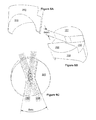
- FIG. 5B is view from above of the same body portion, with a spinal rod overlaid at one extreme orientation.
- FIG. 5C is view from above of the same body portion, with a spinal rod overlaid at the opposite extreme orientation.
- FIG. 5D is an overlay of FIGS. 5B and 5C , with an angle defined.
- FIG. 5E is similar to FIGS. 5B , 5 C and 5 D, with an angle defined.
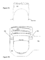
- FIG. 6A is a three-dimensional view of the saddle element partially from below.
- FIG. 6B is a three-dimensional view of the saddle element partially from above.
- FIG. 6C is a view of the saddle element almost directly from above, illustrating possible positions of a control rod relative to the saddle element.
- FIG. 7A is a side view of the saddle element, illustrating a particular external taper.
- FIG. 7B is a sectional view of the body portion, illustrating a corresponding internal taper.
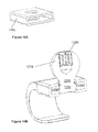
- FIG. 8A is a three-dimensional view of a half-hook in isolation.
- FIG. 8B is a similar view of two half-hooks in isolation.
- FIG. 9A is a three-dimensional view of two half-hooks, a pinion and a partially spherical head.
- FIG. 9B is a view similar to FIG. 9B but from below.
- FIG. 10A is a three-dimensional view of the enclosure.
- FIG. 10B is a three-dimensional sectional view of the enclosure, the half-hooks, the pinion and the partially spherical head.
- FIG. 11A is a three-dimensional view, somewhat from below, of the pinion and the partially spherical head.
- FIG. 11B is a three-dimensional view, somewhat from above, of the pinion and the partially spherical head.
- FIG. 12 is a three-dimensional view of the split-ring.
- FIG. 13A is a three-dimensional view, somewhat from above, of the saddle.
- FIG. 13B is a three-dimensional view, somewhat from below, of the saddle.
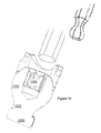
- FIG. 14 is a three-dimensional view of a tool being extended through the central hole in the saddle, to the partially spherical head.
- FIG. 15A is a three-dimensional view, somewhat from above, of the body.
- FIG. 15B is a three-dimensional sectional view of the body.
- FIG. 15C is a three-dimensional view, somewhat from below, of the body.
- FIG. 16A is a three-dimensional sectioned view of the assembled device, excluding the half-hooks.
- FIG. 16B is a three-dimensional view of the assembled device.
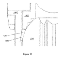
- FIG. 17 which is a close-up of FIG. 16A , illustrates the interaction of the split-ring with other components t so as to provide friction.
- FIG. 18A is a three-dimensional view of an embodiment similar to the embodiment of FIG. 8-17 , but having a smaller overall height.
- FIG. 18B is a three-dimensional sectional view of FIG. 18 .
- FIGS. 19A and 19B are three-dimensional views, from above and below respectively, of the pinion and partially spherical head.
- the offset arm system may, first of all, comprise an arm portion 100 .
- Arm portion 100 may be able to be received in another piece of spinal hardware such as a pedicle screw.
- arm portion 100 is cylindrical, although it is also possible for arm portion 100 to have cross-sectional shapes other than circular.
- Arm portion 100 is illustrated as being straight, although other shapes are possible.
- Arm portion 100 may have a lengthwise direction, which may correspond to a cylindrical axis of the arm portion 100 if arm portion 100 is cylindrical, or, more generally, may correspond to a long dimension of arm portion 100 .
- arm portion 100 may adjoin or be integral with body portion 200 .
- body portion 200 may have a through-hole 210 therethrough, which may be appropriately dimensioned to receive therein a spinal rod.
- Body portion 200 may also have a blind hole 220 , such that blind bole 220 intersects through-hole 210 .
- Blind hole 220 may have an internal surface that is at least partially internally threaded with internal threads 224 , which may be complementary to threads on a setscrew 600 .
- Body portion 200 may also have control rod holes 280 for reception of control rod 550 . As illustrated in FIG. 7B , there may be two such control rod holes 280 , which may be coaxial with each other.
- Control rod 550 may be a press fit in at least one of holes 280 , or may be otherwise secured to body portion 200 .
- the through-hole 210 through the body portion 200 may be shaped and dimensioned so as to accept within it a spinal rod 700 .
- Spinal rod 700 may be cylindrical.
- through-hole 210 through the body portion 200 may be shaped and dimensioned such that it has an entrance region and an exit region that permit the spinal rod 700 to pass through through-hole 210 at a variety of orientations, within certain limits.
- the hole in the body portion 200 through which the spinal rod 700 passes may have a width and angular range and internal shape suitable so that the spinal rod 700 can seat comfortably within it at any angle within the permitted range.
- FIGS. 5A-5E Various views of the through-hole 210 are shown in FIGS. 5A-5E .
- the through-hole 210 may be such as to permit the spinal rod 700 to be oriented through a range of angles in one plane, which may be termed a horizontal plane 132 .
- Through-hole 210 may have, generally along its own hole direction, a narrower central region and it may fan out in either direction away from the central region toward the ends of through-hole 210 .
- the bottom surface of through-hole 210 may have a flat region 216 that may be generally triangular.
- the generally triangular region 216 may have an included angle alpha as labeled in FIG. 5E .
- the angle alpha may also equal or approximately equal the range of angles of spinal rod 700 that can be accommodated, which is illustrated in FIG. 5D and is also labeled alpha.
- the through-hole 210 may be such as to constrain spinal rod 700 to a plane that is horizontal, i.e., allow essentially no range of angular orientation of the spinal rod 700 in a different plane that is orthogonal to the horizontal plane. This is related to the fact that region 216 is flat and may be horizontal, and the underside 310 of saddle element 300 closely fits spinal rod 700 and also may constrain spinal rod 700 to a horizontal plane.
- the saddle element 300 may have a contour that may complement or at least partially complement the exterior of the spinal rod 700 .
- the saddle element 300 On its upper side the saddle element 300 may have a top surface 320 , which may be flat as illustrated, that can contact the underside of the setscrew 600 .
- the saddle element 300 may be able to change its angular position so as to follow the angular position of the spinal rod 700 , by rotating about a vertical axis that is perpendicular to horizontal plane 132 .
- Control rod 550 may serve either or both of two purposes. It may retain the saddle element 300 within the body portion 200 so that when the control rod 550 is in place and the saddle element 300 is within the body portion 200 , the saddle element 300 is blocked so as to be unable to pass the control rod 550 and so as to be unable to exit from the body portion 200 . At the same time, a portion of the saddle element 300 exists alongside the control rod 550 so that the top surface 320 of the saddle element 300 may contact the setscrew 600 .
- the recess 350 may have a shape that has a relatively narrow central region and fans outward in two opposite directions from the central region. The central region may be wide enough to allow space for control rod 550 .
- the fan regions may have an included angle beta, as illustrated in FIG. 6C .
- the included angle beta may be at least approximately equal to the included angle alpha associated with through-hole 210 .
- the recess 350 may have a depth that is deeper than the diameter or vertical dimension of the control rod 550 .
- control rod 550 may be supplied to the surgeon with the saddle element 300 pre-assembled into the body portion 200 and kept in place there by the control rod 550 .
- the surgeon may have fewer loose parts that need to be handled during surgery and may therefore have fewer surgical steps that need to be performed during surgery, all of which are beneficial.
- the control rod 550 may also serve a function of limiting the allowed angular positioning of the saddle element 300 to a certain range.
- the spinal rod 700 when the spinal rod 700 is in place within the body portion 200 , the spinal rod 700 itself encounters limits on its range of angular position due to the spinal rod 700 touching certain surfaces of through-hole 210 or other features of body portion 200 when spinal rod 700 is rotated to certain angular positions.
- the spinal rod 700 when the spinal rod 700 is not present in the body portion 200 , it might have been possible for the saddle element 300 to rotate into a position where the saddle element 300 could block entry of the spinal rod 700 into the through-hole 210 , rather than permitting entry of the spinal rod 700 into the through-hole 210 .
- the spinal rod 700 may be useful to guarantee that the anytime the spinal rod 700 approaches the through-hole 210 , the spinal rod 700 will be able to pass through the through-hole 210 without potentially being blocked by a saddle element 300 whose angular orientation is non-optimal. Guaranteeing this appropriate alignment can be accomplished as described herein by the interaction of the control rod 550 and the recess 320 in saddle element 300 .
- the saddle element 300 may have a taper on its exterior, and the internal surface of body portion 200 against which the saddle element 300 bears may have a similar taper, producing a wedging action.
- the taper may be a Morse Taper. Such tapers may have taper angles that may be equal w each other. In FIGS. 7A and 7B , both tapers are illustrated and are designated as angle gamma.
- the taper may be such that the saddle element 300 bottoms against the spinal rod 700 before the external taper of the saddle element 300 bottoms against the corresponding internal taper feature of the body portion 200 . Any such taper is optional.
- the spinal rod 700 has the ability to have its angular position chosen or adjusted within certain limits.
- the offset arm can sit on the spinal rod at any angle in a range of 30 degrees (approximately 15 degrees to either side of a nominal position).
- the bottom of the spinal rod 700 may touch or be tangent to the flat “fan” region 216 of the lower internal surface of through-hole 210 .
- the top of the spinal rod 700 may be cradled by the lower surface 310 of the saddle element 300 , and saddle element 300 may rotate as needed with respect to body portion 200 .
- a saddle element 300 may be placed between the body portion 200 and the spinal rod 700 .
- the setscrew 600 may bear against the spinal rod 700 , which in turn may bear against the saddle element 300 , which in turn may bear against the body portion 200 .
- FIGS. 8-17 there is shown an Adjustable Hook Assembly.
- a hook assembly that has a polyaxial feature.
- a body capable of gripping a spinal rod may be movably joined to the hook assembly such that relative rotational motion is permitted, within limits, between the hook assembly and the body.
- Such a joint may involve a partially spherical head that is captured within the body that is capable of gripping the spinal rod.
- the adjustable hook assembly may comprise two hook halves 1100 A, 1100 B such that there can he relative motion of the two hook halves relative to each other, such as translational motion.
- There may be a housing 1150 , shown in FIG. 10A , to which both hook halves 1100 A, 1100 B are slideably coupled, or alternatively the two hook halves 1100 A, 1100 B may be slideably coupled to each other.
- Each hook half 1100 A, 1100 B may comprise a rack 1102 A, 1102 B.
- Each rack 1102 A, 1102 B may engage a pinion gear 1200 .
- rotation of the pinion gear 1200 can cause one hook half 1100 A to translate in a first direction, and cause the other hook half 1100 B to translate in the opposite direction.
- the two opposing hook halves 1100 A, 1100 B may be slideably coupled to one another or to an assembly that is common to both hook halves 1100 A, 1100 B. It is possible that hook halves 1100 A, 1100 B, and also pinion 1200 that they engage with, may be at least partially enclosed by a housing 1150 , as illustrated in FIGS. 10A-10B .
- the pinion 1200 may he connected to or integral with a partially spherical head 1250 . which may comprise a portion of a sphere. Between partially spherical head 1250 and pinion 1200 may be a transition region that may be referred to as neck 1220 . Partially spherical head 1250 may have a center, which may be located coincident with the axis of rotation 1210 of pinion 1200 . Partially spherical head 1250 may have, at or near its top, a tool interface 1260 suitable to receive a tool capable of transmitting torque to partially spherical head 1250 .
- the tool interface 1260 may, for example, be an internal hex interface or similar interface as is known in the art.
- the corresponding tool could be a simple hex wrench (Allen wrench) or could be a ball end hex wrench, which would allow approach to the tool interfaced 1260 from more angles than simply along the axis of pinion 1200 . Both are illustrated in FIG. 14 .
- Partially spherical head 1250 may be suitable to be received within another component of spinal hardware.
- the presence of spherical shape of partially spherical head 1250 may allow the adjustable hook assembly to connect with other spinal hardware at a variety of angular orientations, thereby providing the assembly with the ability to adjust in at least one degree of freedom.
- Such adjustability may be polyaxial.
- split ring 1280 may have a shape that forms a substantially large portion of a substantially circular, except for a gap in one place.
- the dimensions of the substantially circular shape may be coordinated with appropriate dimensions of partially spherical head 1250 and body 1400 as desired.
- the cross-sectional shape of split ring 1280 may be rectangular as illustrated, although other cross-sectional shapes are also possible.
- Saddle 1300 may have an axis of symmetry 1310 such that at least some of the features of saddle 1300 may be axisymmetric around that axis.
- Saddle 1300 may have an underside 1320 that is at least approximately spherical in a manner that is complementary to partially spherical head 1250 .
- the underside of saddle 1300 does not have to be smooth, but rather may comprise grooves or sharp edges. Such grooves or sharp edges may bear against the corresponding surface of partially spherical head 1250 for purposes of enhancing grip or friction when the assembly is in a tightened state.
- a curved recess 1330 On the upper side of saddle 1300 , there may be provided a curved recess 1330 , which may be cylindrical or at least partially cylindrical. Curved recess 1330 may be complementary in shape and dimension to a spinal rod. Curved recess 1330 may have a cylindrical axis, which may intersect and be perpendicular to axis of symmetry 1310 . The curved recess 1330 is illustrated as being smooth, although it could alternatively comprise gripping features such as roughness. Saddle 1300 may have a central hole 1340 therethrough, whose axis may coincide with the axis of symmetry 1310 of saddle 1300 . With reference to FIG.
- central hole 1340 may allow access of a tool to the tool interface 1260 that may be present in partially spherical head 1250 .
- central hole 1340 through saddle 1300 may be larger than the maximum transverse dimension of the tool, and may be larger by a sufficient amount so as to allow the tool to approach tool interface 1260 from more directions than just along the axis of symmetry 1310 of saddle 1300 .
- saddle 1300 may have one or more (two are illustrated) retention features 1380 . These retention features 1380 are illustrated as being small cutouts that can receive a retention pin 1490 described elsewhere herein.
- the body 1400 may have a through-hole 1410 therethrough.
- the through-hole 1410 may be of sufficient diameter to allow the pinion 1200 to pass through the through-hole 1410 , but the partially spherical head 1250 may have a diameter larger than the diameter of the through-hole 1410 .
- the body 1400 may further comprise a slot 1420 . which may be generally U-shaped, opening toward the proximal end of body 1400 , and may be suitable to receive a spinal rod.
- Through-hole 1410 may comprise threads 1430 suitable to receive a setscrew 1600 . Such threads 1430 may be interrupted by the slot 1420 .
- the body 1400 may comprise one or more ridges or some form of roughness. Such features may help to grip and lock the position of the partially spherical head 1250 when the entire assembly is in a tightened configuration.
- the body 1400 may further comprise one or more (two are illustrated) retention holes 1480 in the wall of body 1400 , and retention hole(s) 1480 may in turn receive retention pins 1490 .
- Retention pin(s) 1490 may be such as to block passage of saddle 1300 past retention pin(s) 1490 when retention pin 1490 is present in the illustrated position. As such, the assembly may stay together as a single assembly, hut in the absence of tightening of setscrew 1600 against a spinal rod 1700 , there may be some permitted motion of partially spherical head 1250 relative to body 1400 .
- the assembly may also include a setscrew 1600 that may interface with internal threads 1430 in body 1400 .
- the assembly may also include a spinal rod 1700 that may be gripped within the body 1400 between setscrew 1600 and saddle 1300 . Tightening setscrew 1600 may bear against spinal rod 1700 , which in turn may bear against saddle 1300 . Such tightening of setscrew 1600 may result in a lightened configuration of the implant.
- the partially spherical head 1250 When the assembly is in an untightened configuration, the partially spherical head 1250 may be able to rotate with respect to body 1400 and thereby cause translation of hook halves 1100 A, 1100 B. Such translation may cause hook halves 1100 A, 1100 B to come closer to each other or further apart from each other.
- One direction of such motion may establish or tighten a grip of the hook assembly on a body pan. The other direction of such motion may release or loosen the grip of the hook assembly on the body part.
- Split ring 1280 may be dimensioned, and may be dimensioned in conjunction with appropriate dimensions of saddle 1300 and body 1400 , so that even when the assembly is not tightened (such as by the presence of a spinal rod and a setscrew), some friction is maintained. For example, such friction may be appropriate so that whatever orientation body 1400 is set to relative to partially spherical head 1250 , it will remain in that orientation against slight applied force or torque, such as the weight of body 1400 ; but when an appropriate larger amount of, force or torque is applied, the orientation of body 1400 can be changed relative to partially spherical head 1250 .
- split ring 1280 may have a cross-sectional shape that is substantially rectangular, while the overall shape of split-ring 1280 may be generally the shape of a circle with a slight gap missing.
- the cross-sectional shape may be rectangular with an axial dimension that is larger than the thickness of the split-ring 1280 in the plante of split-ring 1280 .
- the natural shape of such a split ring can be a portion of a cylinder (except for the gap).
- Deformation to provide friction could occur due to spreading-apart of the gap of split-ring 1280 .
- deformation to provide friction could occur due to deformation of split-ring 1280 such that the lower edge of the split-ring is forced out to a larger radial location than the radial location of the top edge of the split-ring, resulting in the split-ring being deformed a frusto-conical shape.
- deformation to provide friction could be any combination of those types of deformation.
- the body 1400 may have an internal recess 1440 that may provide space into which the split-ring 1280 may deform or expand.
- the partially spherical head 1250 may contact a lower internal corner of the split-ring 1280 and the body 1400 may contact the split-ring 1280 an upper portion of split-ring 1280 , such as above a midplane of the split-ring 1280 .
- saddle 1300 may push vertically downward on split-ring 1280 .
- Frictional gripping could occur due to spreading-apart of the gap of split-ring 1280 .
- frictional gripping could occur due to deformation of split-ring 1280 such that split-ring is deformed from a cylindrical shape to a frusto-conical shape.
- frictional gripping could occur by any combination of those types of deformation.
- the hardware may be tightened so as to either directly or indirectly exert force on partially spherical head 1250 .
- Such tightening may not only fix the angular position of the hook assembly relative to the other hardware in regard to angulation and translation, but it may also fix the rotational position of the pinion 1200 , so that there is no longer any possibility of opening or closing the hook assembly or loosening or tightening the grip of the hook assembly.
- Rotation of the spherical ball head clockwise or counterclockwise, relative to housing 1150 can move the half-hooks 1100 A, 1100 B either towards each other or away from each other. It is possible that when the body 1400 receives a spinal rod 1700 and the spinal rod 1700 is locked in place such as by a setscrew 1600 , the spinal rod 1700 may bear indirectly (through saddle 1300 ) against the partially spherical head 1250 thereby locking the partially spherical head 1250 in place relative to the body 1400 .
- the adjustable hook assembly may comprise a ratchet that may influence the opening or closing or both of the hook assembly even when the partially spherical head 1250 is not locked into additional spinal hardware.
- the ratchet may permit the hook halves to he drawn closer to each other while not permitting the hook halves 1100 A, 1100 B to spread apart from each other.
- a linear ratchet could be associated with the linear motion of one or both of the hook halves 1100 A, 1100 B.
- a rotary ratchet could be associated with the rotation of pinion 1200 or of a shaft or other component associated with pinion 1200 . Any type of ratchet could be releasable so that motion in a direction not ordinarily permitted by the ratchet would be possible if the ratchet is released.
- Pre-assembly may be such as to create a desired amount of friction so that the body 1400 will maintain a desired position with respect to the partially spherical head 1250 .
- a possible assembly technique may involve starting with the body 1400 , then inserting the pinion 1200 until the bottom of the partially spherical head 1250 bottoms out against the interior surfaces of body 1400 , then inserting the split ring 1280 , then inserting the saddle 1300 so that the saddle 1300 is in loose contact with at least some other components (either the partially spherical head 1250 or the split ring 1280 ), and then capturing the saddle 1300 in place by installing the retention pin(s) 1490 .
- the opening (through-hole) 1412 in the lower part of the body 1400 which is part of through-hole 1410 , is illustrated as being circular, but it does not have to be perfectly circular. Instead, it could be shaped so as to allow the connecting neck 1120 between the pinion 1200 and the partially spherical head 1250 to angulate through a certain amount of angulation in a first direction and a different amount of angulation in a different direction such as a second direction that is perpendicular to the first direction.
- Housing 1150 is illustrated herein, but it is possible that other designs could be used to provide appropriate mechanical connection between half-hooks 1100 A, 1100 B and pinion 1200 and other parts as needed.
- any such device could provide a slight amount of translational adjustment in a direction that is perpendicular to axis of rotation 1210 .
- the hole in housing 1150 through which neck 1220 passes could be somewhat larger than the actual diameter of neck 1220 , or could be a non-circular shape.
- the internal dimensions of housing 1150 could provide some space for half-hooks 1100 A, 1100 B and pinion 1200 to move slightly (small enough distances to avoid disengagement of pinion 1200 from racks 1102 A, 1102 B).
- the total height of the device may be smaller than it is for the design illustrated in FIGS. 8-17 . Having a smaller total height may reduce possible visible protrusion of the device in the skin of the patient.
- the partially spherical head 1250 may have an underside 1900 that is substantially flat. Underside 1900 may, for example, be substantially parallel to a surface of housing 1150 . In this situation, body 1400 may have a bottom that wraps around the underside of partially spherical head 1250 . It can be appreciated that a design as illustrated in FIGS. 18A-19 would not have a polyaxial adjustment ability, or would not have nearly as much polyaxial adjustment ability as the previous embodiment. However, such embodiment would still have the ability for body 1400 to rotate with respect to partially spherical head 1250 around an axis that may coincide with the axis of rotation of pinion 1200 .
- inventive embodiments are presented by way of example only and that, within the scope of the appended claims and equivalents thereto, inventive embodiments may be practiced otherwise than as specifically described and claimed.
- inventive embodiments of the present disclosure are directed to each individual feature, system, article, material, kit, and/or method described herein.
- a reference to “A and/or B”, when used in conjunction with open-ended language such as “comprising” can refer, in one embodiment, to A only (optionally including elements other than B); in another embodiment, to B only (optionally including elements other than A); in yet another embodiment, to both A and B (optionally including other elements); etc.
- the phrase “at least one,” in reference to a list of one or more elements, should be understood to mean at least one element selected from any one or more of the elements in the list of elements, but not necessarily including at least one of each and every element specifically listed within the list of elements and not excluding any combinations of elements in the list of elements.
- This definition also allows that elements may optionally be present other than the elements specifically identified within the list of elements to which the phrase “at least one” refers, whether related or unrelated to those elements specifically identified.
- “at least one of A and B” can refer, in one embodiment, to at least one, optionally including more than one, A, with no B present (and optionally including elements other than B); in another embodiment, to at least one, optionally including more than one, B, with no A present (and optionally including elements other than A); in yet another embodiment, to at least one, optionally including more than one, A, and at least one, optionally including more than one, B (and optionally including other elements); etc.
Abstract
Description
Claims (7)
Priority Applications (1)
| Application Number | Priority Date | Filing Date | Title |
|---|---|---|---|
| US13/925,211 US8992575B1 (en) | 2012-06-22 | 2013-06-24 | Spinal implants having offsets and hooks |
Applications Claiming Priority (2)
| Application Number | Priority Date | Filing Date | Title |
|---|---|---|---|
| US201261663206P | 2012-06-22 | 2012-06-22 | |
| US13/925,211 US8992575B1 (en) | 2012-06-22 | 2013-06-24 | Spinal implants having offsets and hooks |
Publications (1)
| Publication Number | Publication Date |
|---|---|
| US8992575B1 true US8992575B1 (en) | 2015-03-31 |
Family
ID=52707782
Family Applications (1)
| Application Number | Title | Priority Date | Filing Date |
|---|---|---|---|
| US13/925,211 Active US8992575B1 (en) | 2012-06-22 | 2013-06-24 | Spinal implants having offsets and hooks |
Country Status (1)
| Country | Link |
|---|---|
| US (1) | US8992575B1 (en) |
Cited By (13)
| Publication number | Priority date | Publication date | Assignee | Title |
|---|---|---|---|---|
| US20150150602A1 (en) * | 2013-10-14 | 2015-06-04 | Dennis P. Devito | Assembly for treating an isthmic fracture |
| CN105943143A (en) * | 2016-06-30 | 2016-09-21 | 山东威高骨科材料股份有限公司 | Reduction and internal fixation device for injury of lumbar vertebra, sacrum and ilium pelvis |
| US20180125538A1 (en) * | 2012-05-11 | 2018-05-10 | Orthopediatrics Corporation | Surgical connectors and instrumentation |
| US10206719B2 (en) | 2016-12-16 | 2019-02-19 | Nuvasive, Inc. | Bone hook apparatus |
| US10441324B2 (en) | 2016-08-17 | 2019-10-15 | Warsaw Orthopedic, Inc. | Spinal construct and method |
| US10653455B2 (en) | 2017-09-12 | 2020-05-19 | Warsaw Orthopedic, Inc. | Spinal implant system and methods of use |
| US11160587B2 (en) * | 2011-12-08 | 2021-11-02 | Spine Wave, Inc. | Rod connector for attachment to an existing spinal rod |
| US11284924B1 (en) * | 2020-12-16 | 2022-03-29 | Warsaw Orthopedic, Inc | Adjustable spinal implant, system and method |
| US11291477B1 (en) | 2021-05-04 | 2022-04-05 | Warsaw Orthopedic, Inc. | Dorsal adjusting implant and methods of use |
| US11432848B1 (en) | 2021-05-12 | 2022-09-06 | Warsaw Orthopedic, Inc. | Top loading quick lock construct |
| US11712270B2 (en) | 2021-05-17 | 2023-08-01 | Warsaw Orthopedic, Inc. | Quick lock clamp constructs and associated methods |
| US11751919B2 (en) | 2017-02-14 | 2023-09-12 | Warsaw Orthopedic, Inc. | Spinal implant system and method |
| US11957391B2 (en) | 2021-11-01 | 2024-04-16 | Warsaw Orthopedic, Inc. | Bone screw having an overmold of a shank |
Citations (31)
| Publication number | Priority date | Publication date | Assignee | Title |
|---|---|---|---|---|
| US5242445A (en) | 1991-12-05 | 1993-09-07 | Danek Medical, Inc. | Split eyebolt for spinal rod |
| US5549607A (en) | 1993-02-19 | 1996-08-27 | Alphatec Manufacturing, Inc, | Apparatus for spinal fixation system |
| US5601552A (en) | 1994-03-18 | 1997-02-11 | Sofamor, S.N.C. | Fixing device for a rigid transverse connection device between rods of a spinal osteosynthesis system |
| US5609592A (en) | 1993-01-04 | 1997-03-11 | Danek Medical, Inc. | Spinal Fixation System |
| US5702393A (en) * | 1995-12-07 | 1997-12-30 | Groupe Lepine | Assembly device for elongate components of osteosynthesis, especially spinal, equipment |
| US6368320B1 (en) * | 1997-12-09 | 2002-04-09 | (Dimso) Distribution Medicale Du Sud-Ouest | Connector for backbone osteosynthesis device |
| US6413257B1 (en) | 1997-05-15 | 2002-07-02 | Surgical Dynamics, Inc. | Clamping connector for spinal fixation systems |
| US6551318B1 (en) | 2000-07-26 | 2003-04-22 | Stahurski Consulting Inc. | Spinal column retaining apparatus |
| US6554832B2 (en) | 2001-04-02 | 2003-04-29 | Endius Incorporated | Polyaxial transverse connector |
| US6565565B1 (en) | 1998-06-17 | 2003-05-20 | Howmedica Osteonics Corp. | Device for securing spinal rods |
| US6626908B2 (en) | 2000-07-22 | 2003-09-30 | Corin Spinal Systems Limited | Pedicle attachment assembly |
| US6685705B1 (en) * | 2000-10-23 | 2004-02-03 | Sdgi Holdings, Inc. | Six-axis and seven-axis adjustable connector |
| US6755830B2 (en) | 2001-07-04 | 2004-06-29 | Sofamor S.N.C. | Connector for a spinal fixation member |
| US20060200128A1 (en) | 2003-04-04 | 2006-09-07 | Richard Mueller | Bone anchor |
| US7485132B1 (en) | 2000-10-06 | 2009-02-03 | Abbott Spine Inc. | Transverse connector with cam activated engagers |
| US20090036929A1 (en) | 2005-07-22 | 2009-02-05 | Joey Camia Reglos | Offset connector for a spinal stabilization rod |
| US20090204155A1 (en) * | 2005-12-19 | 2009-08-13 | Felix Aschmann | Polyaxial bone anchor with headless pedicle screw |
| US7578833B2 (en) | 2004-12-13 | 2009-08-25 | Dr. Robert S. Bray, Jr. | Bone fastener assembly for bone retention apparatus |
| US7704270B2 (en) | 2004-12-22 | 2010-04-27 | Stryker Spine | Variable offset connectors and bone fixation methods |
| US7850716B2 (en) | 2006-02-17 | 2010-12-14 | Warsaw Orthopedic, Inc. | Adjustable interconnection device |
| US7922746B2 (en) | 2006-08-31 | 2011-04-12 | Warsaw Orthopedic, Inc. | Spinal rod extenders and methods of use |
| US7959653B2 (en) | 2004-09-03 | 2011-06-14 | Lanx, Inc. | Spinal rod cross connector |
| USRE42545E1 (en) | 1995-04-13 | 2011-07-12 | Warsaw Orthopedic, Inc. | Polyaxial pedicle screw having a threaded and tapered compression locking mechanism |
| US20110196425A1 (en) * | 2010-02-05 | 2011-08-11 | Warsaw Orthopedic, Inc. | Connector and Method |
| US8025680B2 (en) | 2004-10-20 | 2011-09-27 | Exactech, Inc. | Systems and methods for posterior dynamic stabilization of the spine |
| US8029546B2 (en) | 2005-12-15 | 2011-10-04 | Warsaw Orthopedic, Inc. | Variable angle offset spinal connector assembly |
| US8029543B2 (en) | 2002-10-28 | 2011-10-04 | Warsaw Othopedic, Inc. | Multi-axial, cross-link connector system for spinal implants |
| US8066743B2 (en) | 2002-10-28 | 2011-11-29 | Warsaw Orthopedic, Inc. | Multi-axial, cross-link connector system for spinal implants |
| US8313516B2 (en) | 2003-06-27 | 2012-11-20 | Depuy Spine, Inc. | Polyaxial bone screw |
| US8361117B2 (en) | 2006-11-08 | 2013-01-29 | Depuy Spine, Inc. | Spinal cross connectors |
| US20130096623A1 (en) * | 2011-09-15 | 2013-04-18 | Lutz Biedermann | Polyaxial bone anchoring device with enlarged pivot angle |
-
2013
- 2013-06-24 US US13/925,211 patent/US8992575B1/en active Active
Patent Citations (32)
| Publication number | Priority date | Publication date | Assignee | Title |
|---|---|---|---|---|
| US5242445A (en) | 1991-12-05 | 1993-09-07 | Danek Medical, Inc. | Split eyebolt for spinal rod |
| US5609592A (en) | 1993-01-04 | 1997-03-11 | Danek Medical, Inc. | Spinal Fixation System |
| US5549607A (en) | 1993-02-19 | 1996-08-27 | Alphatec Manufacturing, Inc, | Apparatus for spinal fixation system |
| US5743911A (en) | 1994-03-18 | 1998-04-28 | Sofamor S.N.C. | Fixing device for a rigid transverse connection device between rods of a spinal osteosynthesis system |
| US5601552A (en) | 1994-03-18 | 1997-02-11 | Sofamor, S.N.C. | Fixing device for a rigid transverse connection device between rods of a spinal osteosynthesis system |
| USRE42545E1 (en) | 1995-04-13 | 2011-07-12 | Warsaw Orthopedic, Inc. | Polyaxial pedicle screw having a threaded and tapered compression locking mechanism |
| US5702393A (en) * | 1995-12-07 | 1997-12-30 | Groupe Lepine | Assembly device for elongate components of osteosynthesis, especially spinal, equipment |
| US6413257B1 (en) | 1997-05-15 | 2002-07-02 | Surgical Dynamics, Inc. | Clamping connector for spinal fixation systems |
| US6368320B1 (en) * | 1997-12-09 | 2002-04-09 | (Dimso) Distribution Medicale Du Sud-Ouest | Connector for backbone osteosynthesis device |
| US6565565B1 (en) | 1998-06-17 | 2003-05-20 | Howmedica Osteonics Corp. | Device for securing spinal rods |
| US6626908B2 (en) | 2000-07-22 | 2003-09-30 | Corin Spinal Systems Limited | Pedicle attachment assembly |
| US6551318B1 (en) | 2000-07-26 | 2003-04-22 | Stahurski Consulting Inc. | Spinal column retaining apparatus |
| US7485132B1 (en) | 2000-10-06 | 2009-02-03 | Abbott Spine Inc. | Transverse connector with cam activated engagers |
| US6685705B1 (en) * | 2000-10-23 | 2004-02-03 | Sdgi Holdings, Inc. | Six-axis and seven-axis adjustable connector |
| US6554832B2 (en) | 2001-04-02 | 2003-04-29 | Endius Incorporated | Polyaxial transverse connector |
| US6755830B2 (en) | 2001-07-04 | 2004-06-29 | Sofamor S.N.C. | Connector for a spinal fixation member |
| US8066743B2 (en) | 2002-10-28 | 2011-11-29 | Warsaw Orthopedic, Inc. | Multi-axial, cross-link connector system for spinal implants |
| US8029543B2 (en) | 2002-10-28 | 2011-10-04 | Warsaw Othopedic, Inc. | Multi-axial, cross-link connector system for spinal implants |
| US20060200128A1 (en) | 2003-04-04 | 2006-09-07 | Richard Mueller | Bone anchor |
| US8313516B2 (en) | 2003-06-27 | 2012-11-20 | Depuy Spine, Inc. | Polyaxial bone screw |
| US7959653B2 (en) | 2004-09-03 | 2011-06-14 | Lanx, Inc. | Spinal rod cross connector |
| US8025680B2 (en) | 2004-10-20 | 2011-09-27 | Exactech, Inc. | Systems and methods for posterior dynamic stabilization of the spine |
| US7578833B2 (en) | 2004-12-13 | 2009-08-25 | Dr. Robert S. Bray, Jr. | Bone fastener assembly for bone retention apparatus |
| US7704270B2 (en) | 2004-12-22 | 2010-04-27 | Stryker Spine | Variable offset connectors and bone fixation methods |
| US20090036929A1 (en) | 2005-07-22 | 2009-02-05 | Joey Camia Reglos | Offset connector for a spinal stabilization rod |
| US8029546B2 (en) | 2005-12-15 | 2011-10-04 | Warsaw Orthopedic, Inc. | Variable angle offset spinal connector assembly |
| US20090204155A1 (en) * | 2005-12-19 | 2009-08-13 | Felix Aschmann | Polyaxial bone anchor with headless pedicle screw |
| US7850716B2 (en) | 2006-02-17 | 2010-12-14 | Warsaw Orthopedic, Inc. | Adjustable interconnection device |
| US7922746B2 (en) | 2006-08-31 | 2011-04-12 | Warsaw Orthopedic, Inc. | Spinal rod extenders and methods of use |
| US8361117B2 (en) | 2006-11-08 | 2013-01-29 | Depuy Spine, Inc. | Spinal cross connectors |
| US20110196425A1 (en) * | 2010-02-05 | 2011-08-11 | Warsaw Orthopedic, Inc. | Connector and Method |
| US20130096623A1 (en) * | 2011-09-15 | 2013-04-18 | Lutz Biedermann | Polyaxial bone anchoring device with enlarged pivot angle |
Cited By (18)
| Publication number | Priority date | Publication date | Assignee | Title |
|---|---|---|---|---|
| US11160587B2 (en) * | 2011-12-08 | 2021-11-02 | Spine Wave, Inc. | Rod connector for attachment to an existing spinal rod |
| US10729472B2 (en) * | 2012-05-11 | 2020-08-04 | Orthopediatrics Corporation | Surgical connectors and instrumentation |
| US20180125538A1 (en) * | 2012-05-11 | 2018-05-10 | Orthopediatrics Corporation | Surgical connectors and instrumentation |
| US9510864B2 (en) * | 2013-10-14 | 2016-12-06 | Medicrea International | Assembly for treating an isthmic fracture |
| US20150150602A1 (en) * | 2013-10-14 | 2015-06-04 | Dennis P. Devito | Assembly for treating an isthmic fracture |
| CN105943143A (en) * | 2016-06-30 | 2016-09-21 | 山东威高骨科材料股份有限公司 | Reduction and internal fixation device for injury of lumbar vertebra, sacrum and ilium pelvis |
| US10441324B2 (en) | 2016-08-17 | 2019-10-15 | Warsaw Orthopedic, Inc. | Spinal construct and method |
| US10893891B2 (en) | 2016-12-16 | 2021-01-19 | Nuvasive, Inc. | Bone hook apparatus |
| US10206719B2 (en) | 2016-12-16 | 2019-02-19 | Nuvasive, Inc. | Bone hook apparatus |
| US11786274B2 (en) | 2016-12-16 | 2023-10-17 | Nuvasive, Inc. | Bone hook apparatus |
| US11751919B2 (en) | 2017-02-14 | 2023-09-12 | Warsaw Orthopedic, Inc. | Spinal implant system and method |
| US11944354B2 (en) | 2017-02-14 | 2024-04-02 | Warsaw Orthopedic, Inc. | Spinal implant system and method |
| US10653455B2 (en) | 2017-09-12 | 2020-05-19 | Warsaw Orthopedic, Inc. | Spinal implant system and methods of use |
| US11284924B1 (en) * | 2020-12-16 | 2022-03-29 | Warsaw Orthopedic, Inc | Adjustable spinal implant, system and method |
| US11291477B1 (en) | 2021-05-04 | 2022-04-05 | Warsaw Orthopedic, Inc. | Dorsal adjusting implant and methods of use |
| US11432848B1 (en) | 2021-05-12 | 2022-09-06 | Warsaw Orthopedic, Inc. | Top loading quick lock construct |
| US11712270B2 (en) | 2021-05-17 | 2023-08-01 | Warsaw Orthopedic, Inc. | Quick lock clamp constructs and associated methods |
| US11957391B2 (en) | 2021-11-01 | 2024-04-16 | Warsaw Orthopedic, Inc. | Bone screw having an overmold of a shank |
Similar Documents
| Publication | Publication Date | Title |
|---|---|---|
| US8992575B1 (en) | Spinal implants having offsets and hooks | |
| US20220096130A1 (en) | Receiving part for receiving a rod for coupling the rod to a bone anchoring element | |
| JP6076648B2 (en) | Multiaxial bone anchoring system | |
| US9247965B2 (en) | Polyaxial bone anchoring device with enlarged pivot angle | |
| JP6527352B2 (en) | Instruments and systems for holding and inserting bone anchors into bone and systems of bone anchors | |
| US8133262B2 (en) | Large diameter bone anchor assembly | |
| US9345516B2 (en) | Polyaxial bone anchoring device | |
| EP2765934B1 (en) | Bone anchor assemblies | |
| US20080015597A1 (en) | Large diameter bone anchor assembly | |
| US9005249B2 (en) | Spinal rod connector assembly | |
| AU2006270487A1 (en) | Bi-polar bone screw assembly | |
| US20080015580A1 (en) | Large diameter bone anchor assembly | |
| US20050070901A1 (en) | Bone fixation assembly and method | |
| US20080015596A1 (en) | Large diameter multiple piece bone anchor assembly | |
| JP2010155076A (en) | Receiving part for receiving rod for coupling the rod to bone anchoring element and bone anchoring device having the receiving part | |
| WO2007114834A1 (en) | Multi-axial, double locking bone screw assembly | |
| US20130110178A1 (en) | High angulation polyaxial bone anchoring device | |
| WO2007040553A1 (en) | Hybrid jointed bone screw system | |
| TW201316943A (en) | A locking assembly for a polyaxial bone anchoring device | |
| JP6122040B2 (en) | Closed head multiaxial and single screw | |
| US9345519B1 (en) | Pedicle screw | |
| US7951171B2 (en) | Polyaxial surgical rod fixation assembly | |
| US20220354546A1 (en) | Connectors, systems, and methods therof | |
| WO2007011407A1 (en) | Universal link bone screw system |
Legal Events
| Date | Code | Title | Description |
|---|---|---|---|
| AS | Assignment |
Owner name: SEASPINE, INC., CALIFORNIA Free format text: ASSIGNMENT OF ASSIGNORS INTEREST;ASSIGNORS:DI LAURO, MICHAEL;SJOVOLD, SIMON;SIGNING DATES FROM 20131203 TO 20131211;REEL/FRAME:031934/0812 |
|
| STCF | Information on status: patent grant |
Free format text: PATENTED CASE |
|
| AS | Assignment |
Owner name: WELLS FARGO BANK, NATIONAL ASSOCIATION, CALIFORNIA Free format text: SECURITY INTEREST;ASSIGNORS:SEASPINE HOLDINGS CORPORATION;SEASPINE ORTHOPEDICS CORPORATION;SEASPINE, INC.;AND OTHERS;REEL/FRAME:037393/0895 Effective date: 20151224 |
|
| FEPP | Fee payment procedure |
Free format text: ENTITY STATUS SET TO SMALL (ORIGINAL EVENT CODE: SMAL) |
|
| MAFP | Maintenance fee payment |
Free format text: PAYMENT OF MAINTENANCE FEE, 4TH YR, SMALL ENTITY (ORIGINAL EVENT CODE: M2551); ENTITY STATUS OF PATENT OWNER: SMALL ENTITY Year of fee payment: 4 |
|
| FEPP | Fee payment procedure |
Free format text: ENTITY STATUS SET TO UNDISCOUNTED (ORIGINAL EVENT CODE: BIG.); ENTITY STATUS OF PATENT OWNER: LARGE ENTITY |
|
| AS | Assignment |
Owner name: WELLS FARGO BANK, NATIONAL ASSOCIATION, AS AGENT, CALIFORNIA Free format text: SECOND AMENDMENT TO PATENT SECURITY AGREEMENT;ASSIGNORS:SEASPINE HOLDINGS CORPORATION;SEASPINE ORTHOPEDICS CORPORATION;SEASPINE, INC.;AND OTHERS;REEL/FRAME:060715/0395 Effective date: 20220715 |
|
| MAFP | Maintenance fee payment |
Free format text: PAYMENT OF MAINTENANCE FEE, 8TH YEAR, LARGE ENTITY (ORIGINAL EVENT CODE: M1552); ENTITY STATUS OF PATENT OWNER: LARGE ENTITY Year of fee payment: 8 |
|
| AS | Assignment |
Owner name: 7D SURGICAL USA INC., CALIFORNIA Free format text: RELEASE BY SECURED PARTY;ASSIGNOR:WELLS FARGO BANK, NATIONAL ASSOCIATION;REEL/FRAME:062336/0593 Effective date: 20230105 Owner name: SEASPINE ORTHOPEDICS INTERMEDIATECO, INC., CALIFORNIA Free format text: RELEASE BY SECURED PARTY;ASSIGNOR:WELLS FARGO BANK, NATIONAL ASSOCIATION;REEL/FRAME:062336/0593 Effective date: 20230105 Owner name: THEKEN SPINE, LLC, CALIFORNIA Free format text: RELEASE BY SECURED PARTY;ASSIGNOR:WELLS FARGO BANK, NATIONAL ASSOCIATION;REEL/FRAME:062336/0593 Effective date: 20230105 Owner name: ISOTIS ORTHOBIOLOGICS, INC., CALIFORNIA Free format text: RELEASE BY SECURED PARTY;ASSIGNOR:WELLS FARGO BANK, NATIONAL ASSOCIATION;REEL/FRAME:062336/0593 Effective date: 20230105 Owner name: SEASPINE SALES LLC, CALIFORNIA Free format text: RELEASE BY SECURED PARTY;ASSIGNOR:WELLS FARGO BANK, NATIONAL ASSOCIATION;REEL/FRAME:062336/0593 Effective date: 20230105 Owner name: ISOTIS, INC., CALIFORNIA Free format text: RELEASE BY SECURED PARTY;ASSIGNOR:WELLS FARGO BANK, NATIONAL ASSOCIATION;REEL/FRAME:062336/0593 Effective date: 20230105 Owner name: SEASPINE, INC., CALIFORNIA Free format text: RELEASE BY SECURED PARTY;ASSIGNOR:WELLS FARGO BANK, NATIONAL ASSOCIATION;REEL/FRAME:062336/0593 Effective date: 20230105 Owner name: SEASPINE ORTHOPEDICS CORPORATION, CALIFORNIA Free format text: RELEASE BY SECURED PARTY;ASSIGNOR:WELLS FARGO BANK, NATIONAL ASSOCIATION;REEL/FRAME:062336/0593 Effective date: 20230105 Owner name: SEASPINE HOLDINGS CORPORATION, CALIFORNIA Free format text: RELEASE BY SECURED PARTY;ASSIGNOR:WELLS FARGO BANK, NATIONAL ASSOCIATION;REEL/FRAME:062336/0593 Effective date: 20230105 |
|
| AS | Assignment |
Owner name: JPMORGAN CHASE BANK, N.A., AS ADMINISTRATIVE ASSISTANT, ILLINOIS Free format text: SECURITY INTEREST;ASSIGNORS:SEASPINE ORTHOPEDICS CORPORATION;SEASPINE, INC.;ISOTIS ORTHOBIOLOGICS, INC.;AND OTHERS;REEL/FRAME:062819/0650 Effective date: 20230217 |
|
| AS | Assignment |
Owner name: BLUE TORCH FINANCE LLC, AS COLLATERAL AGENT, NEW YORK Free format text: SECURITY INTEREST;ASSIGNOR:SEASPINE, INC.;REEL/FRAME:066257/0718 Effective date: 20231106 |