US8992331B2 - Varying thickness armrest with integrated multi-level button panel - Google Patents
Varying thickness armrest with integrated multi-level button panel Download PDFInfo
- Publication number
- US8992331B2 US8992331B2 US13/628,512 US201213628512A US8992331B2 US 8992331 B2 US8992331 B2 US 8992331B2 US 201213628512 A US201213628512 A US 201213628512A US 8992331 B2 US8992331 B2 US 8992331B2
- Authority
- US
- United States
- Prior art keywords
- button
- buttons
- support padding
- cabinet
- gaming system
- Prior art date
- Legal status (The legal status is an assumption and is not a legal conclusion. Google has not performed a legal analysis and makes no representation as to the accuracy of the status listed.)
- Active, expires
Links
Images


Classifications
-
- G—PHYSICS
- G07—CHECKING-DEVICES
- G07F—COIN-FREED OR LIKE APPARATUS
- G07F17/00—Coin-freed apparatus for hiring articles; Coin-freed facilities or services
- G07F17/32—Coin-freed apparatus for hiring articles; Coin-freed facilities or services for games, toys, sports, or amusements
- G07F17/3202—Hardware aspects of a gaming system, e.g. components, construction, architecture thereof
- G07F17/3204—Player-machine interfaces
- G07F17/3209—Input means, e.g. buttons, touch screen
-
- G—PHYSICS
- G07—CHECKING-DEVICES
- G07F—COIN-FREED OR LIKE APPARATUS
- G07F17/00—Coin-freed apparatus for hiring articles; Coin-freed facilities or services
- G07F17/32—Coin-freed apparatus for hiring articles; Coin-freed facilities or services for games, toys, sports, or amusements
- G07F17/3202—Hardware aspects of a gaming system, e.g. components, construction, architecture thereof
- G07F17/3204—Player-machine interfaces
- G07F17/3211—Display means
-
- G—PHYSICS
- G07—CHECKING-DEVICES
- G07F—COIN-FREED OR LIKE APPARATUS
- G07F17/00—Coin-freed apparatus for hiring articles; Coin-freed facilities or services
- G07F17/32—Coin-freed apparatus for hiring articles; Coin-freed facilities or services for games, toys, sports, or amusements
- G07F17/3202—Hardware aspects of a gaming system, e.g. components, construction, architecture thereof
- G07F17/3216—Construction aspects of a gaming system, e.g. housing, seats, ergonomic aspects
Definitions
- the present invention relates generally to a gaming apparatus, and methods for playing wagering games, and more particularly, to an armrest having a varying thickness and an integrated button panel for enhancing player comfort and ease of play.
- Gaming terminals such as slot machines, video poker machines and the like, have been a cornerstone of the gaming industry for several years. Generally, the popularity of such machines with players is dependent on the likelihood (or perceived likelihood) of winning money at the machine and the intrinsic entertainment value of the machine relative to other available gaming options.
- the gaming terminals typically include a cabinet for housing internal components and a game interface for accepting player inputs.
- Most game interfaces include a button panel having an array of buttons mounted on a generally horizontal plate and occupying a substantial area of a cabinet surface that is designated as an interface portion.
- a soft wrist support is positioned proximal to the button array for player comfort.
- a gaming system includes a display mounted to a cabinet and configured to display an outcome of a wagering game, the outcome being randomly selected from a plurality of outcomes in response to receiving a wager.
- the gaming system further includes an armrest panel mounted to the cabinet and including a support padding having a wall thickness defined by an exterior surface and an interior surface. The wall thickness varies along a cross-section of the support padding.
- the armrest panel further includes a plurality of buttons integrated in the support padding for receiving inputs from a player, the plurality of buttons including a first button mounted on a first elevation of the support padding and a second button mounted on a second elevation of the support padding. The first elevation is higher than the second elevation relative to the interior surface.
- a gaming system includes a first gaming terminal, a second gaming terminal, and an armrest panel.
- the first gaming terminal has a first cabinet and at least one first display, the first display being mounted to the first cabinet and configured to display a first outcome of a first wagering game. The first outcome is randomly selected from a first plurality of outcomes in response to receiving a first wager.
- the second gaming terminal has a second cabinet and at least one second display, the second display being mounted to the second cabinet and configured to display a second outcome of a second wagering game. The second outcome is randomly selected from a second plurality of outcomes in response to receiving a second wager.
- the armrest panel is mountable to, one at a time, the first cabinet and the second cabinet, and includes a support padding having a varying wall thickness along a plurality of sections.
- the plurality of sections includes an armrest section.
- the armrest panel further includes a plurality of buttons integrated in the support padding for receiving inputs from a player.
- the plurality of buttons includes a first cluster of buttons and a second cluster of buttons, the first cluster of buttons being in a recessed position relative to the second cluster of buttons.
- a gaming terminal includes a cabinet, at least one display, and an armrest panel.
- the display is mounted to the cabinet and is configured to display an outcome of a wagering game, the outcome being randomly selected from a plurality of outcomes in response to receiving a wager.
- the armrest panel is mounted to the cabinet and includes a support padding having a plurality of integrated buttons, the support padding having a plurality of sections with varying wall thickness.
- the plurality of integrated buttons includes a first button and a second button, the first button being located, with respect to a player position, in a recessed position relative to a second button.
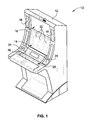
- FIG. 1 is a perspective view of a free-standing gaming terminal according to an embodiment of the present invention.
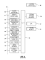
- FIG. 2 is a schematic view of a gaming system according to an embodiment of the present invention.
- FIG. 3 is an image of an exemplary basic-game screen of a wagering game displayed on a gaming terminal, according to an embodiment of the present invention.
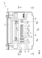
- FIG. 4 is an isometric view of a display and armrest area, according to an embodiment of the present invention.
- FIG. 5 is a front view of the display and armrest area.
- FIG. 6 is a left view of the display and armrest area.
- FIG. 7 is a right view of the display and armrest area.
- FIG. 8 is a bottom view of the display and armrest area.
- FIG. 9 is a top view of the display and armrest area.
- FIG. 10A is a cross-sectional view along lines A-A of FIG. 9 .
- FIG. 10 B is a cross-sectional view along lines B-B of FIG. 9 .
- FIG. 10C is a cross-sectional view along lines C-C of FIG. 9 .
- FIG. 10D is a cross-sectional view along lines D-D of FIG. 9 .
- FIG. 10E is a cross-sectional view along lines E-E of FIG. 9 .
- FIG. 11A is an isometric view of a display and armrest area with a wand assembly, according to an embodiment of the present invention.
- FIG. 11B is an enlarged view of the wand assembly.
- the gaming terminal 10 may be any type of gaming terminal and may have varying structures and methods of operation.
- the gaming terminal 10 is be an electromechanical gaming terminal configured to play mechanical slots
- the gaming terminal is an electronic gaming terminal configured to play a video casino game, such as slots, keno, poker, blackjack, roulette, craps, etc.
- the gaming terminal 10 is shown as a free-standing terminal of the upright type, the gaming terminal is readily amenable to implementation in a wide variety of other forms such as a free-standing terminal of the slant-top type, a portable or handheld device primarily used for gaming, such as is disclosed by way of example in PCT Patent Application No. PCT/US2007/000792 filed Jan. 11, 2007, titled “Handheld Device for Wagering Games,” which is incorporated herein by reference in its entirety, a mobile telecommunications device such as a mobile telephone or personal digital assistant (PDA), a counter-top or bar-top gaming terminal, or other personal electronic device, such as a portable television, MP3 player, entertainment device, etcetera.
- PDA personal digital assistant
- the gaming terminal 10 illustrated in FIG. 1 comprises a cabinet or housing 12 .
- this embodiment of the gaming terminal 10 includes a primary display area 14 , a secondary display area 16 , and one or more audio speakers 18 .
- the primary display area 14 and/or secondary display area 16 variously displays information associated with wagering games, non-wagering games, community games, progressives, advertisements, services, premium entertainment, text messaging, emails, alerts or announcements, broadcast information, subscription information, etc. appropriate to the particular mode(s) of operation of the gaming terminal.
- a bill validator 20 includes a bill validator 20 , a coin acceptor (not shown), one or more information readers 24 , one or more player-input devices 26 , and one or more player-accessible ports 28 (e.g., an audio output jack for headphones, a video headset jack, a wireless transmitter/receiver, etc., shown in FIG. 2 ). While these typical components found in the gaming terminal 10 are described below, it should be understood that numerous other peripheral devices and other elements exist and are readily utilizable in any number of combinations to create various forms of a gaming terminal in accord with the present concepts.
- the primary display area 14 includes, in various aspects of the present concepts, a mechanical-reel display, a video display, or a combination thereof in which a transmissive video display is disposed in front of the mechanical-reel display to portray a video image in superposition over the mechanical-reel display. Further information concerning the latter construction is disclosed in U.S. Pat. No. 6,517,433 to Loose et al. entitled “Reel Spinning Slot Machine With Superimposed Video Image,” which is incorporated herein by reference in its entirety.
- the video display is, in various embodiments, a cathode ray tube (CRT), a high-resolution liquid crystal display (LCD), a plasma display, a light emitting diode (LED), a DLP projection display, an electroluminescent (EL) panel, or any other type of display suitable for use in the gaming terminal 10 , or other form factor, such as is shown by way of example in FIG. 1 .
- the primary display area 14 includes, in relation to many aspects of wagering games conducted on the gaming terminal 10 , one or more paylines 30 (see FIG. 3 ) extending along a portion of the primary display area.
- the primary display area 14 comprises a plurality of mechanical reels 32 and a video display 34 (see FIG.
- the mechanical reels 32 are optionally removed from the interior of the terminal and the video display 34 is advantageously of a non-transmissive type.
- the video display 34 depicted in FIG. 1 is replaced with a conventional glass panel.
- the video display 34 is disposed to overlay another video display, rather than a mechanical-reel display, such that the primary display area 14 includes layered or superimposed video displays.
- the mechanical-reel display of the above-noted embodiments is replaced with another mechanical or physical member or members such as, but not limited to, a mechanical wheel (e.g., a roulette game), dice, a pachinko board, or a diorama presenting a three-dimensional model of a game environment.
- Video images in the primary display area 14 and/or the secondary display area 16 are rendered in two-dimensional (e.g., using Flash MacromediaTM) or three-dimensional graphics (e.g., using RenderwareTM).
- the video images are played back (e.g., from a recording stored on the gaming terminal 10 ), streamed (e.g., from a gaming network), or received as a TV signal (e.g., either broadcast or via cable) and such images can take different forms, such as animated images, computer-generated images, or “real-life” images, either prerecorded (e.g., in the case of marketing/promotional material) or as live footage.
- the format of the video images can include any format including, but not limited to, an analog format, a standard digital format, or a high-definition (HD) digital format.
- the player-input or user-input device(s) 26 include, by way of example, a plurality of buttons 36 on a button panel, as shown in FIG. 1 , a mouse, a joy stick, a switch, a microphone, and/or a touch screen mounted over the primary display area 14 and/or the secondary display area 16 and having one or more soft touch keys.
- the player-input devices 26 comprise technologies that do not rely upon physical contact between the player and the gaming terminal, such as speech-recognition technology, gesture-sensing technology, eye-tracking technology, etc.
- the player-input or user-input device(s) 26 thus accept(s) player input(s) and transforms the player input(s) to electronic data signals indicative of a player input or inputs corresponding to an enabled feature for such input(s) at a time of activation (e.g., pressing a “Max Bet” button or soft key to indicate a player's desire to place a maximum wager to play the wagering game).
- the input(s), once transformed into electronic data signals, are output to a CPU or controller 42 (see FIG. 2 ) for processing.
- the electronic data signals are selected from a group consisting essentially of an electrical current, an electrical voltage, an electrical charge, an optical signal, an optical element, a magnetic signal, and a magnetic element.
- the information reader 24 (or information reader/writer) is preferably located on the front of the housing 12 and comprises, in at least some forms, a ticket reader, card reader, bar code scanner, wireless transceiver (e.g., RFID, Bluetooth, etc.), biometric reader, or computer-readable-storage-medium interface.
- the information reader may comprise a physical and/or electronic writing element to permit writing to a ticket, a card, or computer-readable-storage-medium.
- the information reader 24 permits information to be transmitted from a portable medium (e.g., ticket, voucher, coupon, casino card, smart card, debit card, credit card, etc.) to the information reader 24 to enable the gaming terminal 10 or associated external system to access an account associated with cashless gaming, to facilitate player tracking or game customization, to retrieve a saved-game state, to store a current-game state, to cause data transfer, and/or to facilitate access to casino services, such as is more fully disclosed, by way of example, in U.S. Patent Publication No. 2003/0045354, published on Mar. 6, 2003, entitled “Portable Data Unit for Communicating With Gaming Machine Over Wireless Link,” which is incorporated herein by reference in its entirety.
- a portable medium e.g., ticket, voucher, coupon, casino card, smart card, debit card, credit card, etc.
- the noted account associated with cashless gaming is, in some aspects of the present concepts, stored at an external system 46 (see FIG. 2 ) as more fully disclosed in U.S. Pat. No. 6,280,328 to Holch et al. entitled “Cashless Computerized Video Game System and Method,” which is incorporated herein by reference in its entirety, or is alternatively stored directly on the portable storage medium.
- Various security protocols or features can be used to enhance security of the portable storage medium.
- the individual carrying the portable storage medium is required to enter a secondary independent authenticator (e.g., password, PIN number, biometric, etc.) to access the account stored on the portable storage medium.
- a secondary independent authenticator e.g., password, PIN number, biometric, etc.
- the various components of the gaming terminal 10 are controlled by one or more processors (e.g., CPU, distributed processors, etc.) 42 , also referred to herein generally as a controller (e.g., microcontroller, microprocessor, etc.).
- the controller 42 can include any suitable processor(s), such as an Intel® Pentium processor, Intel® Core 2 Duo processor, AMD OpteronTM processor, or UltraSPARC® processor.
- the controller 42 includes a plurality of microprocessors including a master processor, a slave processor, and a secondary or parallel processor.
- Controller 42 comprises any combination of hardware, software, and/or firmware disposed in and/or disposed outside of the gaming terminal 10 that is configured to communicate with and/or control the transfer of data between the gaming terminal 10 and a bus, another computer, processor, or device and/or a service and/or a network.
- the controller 42 comprises one or more controllers or processors and such one or more controllers or processors need not be disposed proximal to one another and may be located in different devices and/or in different locations.
- a first processor is disposed proximate a user interface device (e.g., a push button panel, a touch screen display, etc.) and a second processor is disposed remotely from the first processor, the first and second processors being electrically connected through a network.
- the first processor is disposed in a first enclosure (e.g., a gaming machine) and a second processor is disposed in a second enclosure (e.g., a server) separate from the first enclosure, the first and second processors being communicatively connected through a network.
- the controller 42 is operable to execute all of the various gaming methods and other processes disclosed herein.
- the controller 42 executes one or more game programs comprising machine-executable instructions stored in local and/or remote computer-readable data storage media (e.g., memory 44 or other suitable storage device).
- computer-readable data storage media, or “computer-readable medium,” as used herein refers to any media/medium that participates in providing instructions to controller 42 for execution.
- the computer-readable medium comprises, in at least some exemplary forms, non-volatile media (e.g., optical disks, magnetic disks, etc.), volatile media (e.g., dynamic memory, RAM), and transmission media (e.g., coaxial cables, copper wire, fiber optics, radio frequency (RF) data communication, infrared (IR) data communication, etc).
- RF radio frequency
- IR infrared
- Computer-readable media include, for example, a hard disk, magnetic tape (or other magnetic medium), a 2-D or 3-D optical disc (e.g., a CD-ROM, DVD, etc.), RAM, PROM, EPROM, FLASH-EPROM, any other memory chip or solid state digital data storage device, a carrier wave, or any other medium from which a computer can read.
- a plurality of storage media or devices are provided, a first storage device being disposed proximate the user interface device and a second storage device being disposed remotely from the first storage device, wherein a network is connected intermediate the first one and second one of the storage devices.
- Various forms of computer-readable media may be involved in carrying one or more sequences of one or more instructions to controller 42 for execution.
- the instructions may initially be borne on a data storage device of a remote device (e.g., a remote computer, server, or system).
- the remote device can load the instructions into its dynamic memory and send the instructions over a telephone line or other communication path using a modem or other communication device appropriate to the communication path.
- a modem or other communication device local to the gaming terminal 10 or to an external system 46 associated with the gaming machine can receive the data on the telephone line or conveyed through the communication path (e.g., via external systems interface 58 ) and output the data to a bus, which transmits the data to the system memory 44 associated with the processor 42 , from which system memory the processor retrieves and executes the instructions.
- the controller 42 is able to send and receive data, via carrier signals, through the network(s), network link, and communication interface.
- the data includes, in various examples, instructions, commands, program code, player data, and game data.
- the controller 42 uses a local random number generator (RNG) to randomly generate a wagering game outcome from a plurality of possible outcomes.
- RNG local random number generator
- the outcome is centrally determined using either an RNG or pooling scheme at a remote controller included, for example, within the external system 46 .
- the controller 42 is coupled to the system memory 44 .
- the system memory 44 is shown to comprise a volatile memory (e.g., a random-access memory (RAM)) and a non-volatile memory (e.g., an EEPROM), but optionally includes multiple RAM and multiple program memories.
- RAM random-access memory
- EEPROM non-volatile memory
- the controller 42 is also coupled to a money/credit detector 48 .
- the money/credit detector 48 is configured to output a signal the controller 42 that money and/or credits have been input via one or more value-input devices, such as the bill validator 20 (see FIG. 1 ), the coin acceptor, or via other sources, such as a cashless gaming account, etc.
- the value-input device(s) is integrated with the housing 12 of the gaming terminal 10 and is connected to the remainder of the components of the gaming terminal 10 , as appropriate, via a wired connection, such as I/O 56 , or wireless connection.
- the money/credit detector 48 detects the input of valid funds into the gaming terminal 10 (e.g., via currency, electronic funds, ticket, card, etc.) via the value-input device(s) and outputs a signal to the controller 42 carrying data regarding the input value of the valid funds.
- the controller 42 extracts the data from these signals from the money/credit detector 48 , analyzes the associated data, and transforms the data corresponding to the input value into an equivalent credit balance that is available to the player for subsequent wagers on the gaming terminal 10 , such transforming of the data being effected by software, hardware, and/or firmware configured to associate the input value to an equivalent credit value.
- the input value is already in a credit value form, such as in a cashless gaming account having stored therein a credit value, the wager is simply deducted from the available credit balance.
- the controller 42 is also connected to, and controls, the primary display area 14 , the player-input device(s) 26 , and a payoff mechanism 50 .
- the payoff mechanism 50 is operable in response to instructions from the controller 42 to award a payoff to the player in response to certain winning outcomes that occur in the base game, the bonus game(s), or via an external game or event.
- the payoff is provided in the form of money, credits, redeemable points, advancement within a game, access to special features within a game, services, another exchangeable media, or any combination thereof.
- payoffs may be paid out in coins and/or currency bills
- payoffs are alternatively associated with a coded ticket (from a ticket printer 52 ), a portable storage medium or device (e.g., a card magnetic strip), or are transferred to or transmitted to a designated player account.
- the payoff amounts distributed by the payoff mechanism 50 are determined by one or more pay tables stored in the system memory 44 .
- I/O circuit 56 Communications between the controller 42 and both the peripheral components of the gaming terminal 10 and the external system 46 occur through input/output (I/O) circuit 56 , which can include any suitable bus technologies, such as an AGTL+ frontside bus and a PCI backside bus. Although the I/O circuit 56 is shown as a single block, it should be appreciated that the I/O circuit 56 alternatively includes a number of different types of I/O circuits. Furthermore, in some embodiments, the components of the gaming terminal 10 can be interconnected according to any suitable interconnection architecture (e.g., directly connected, hypercube, etc.).
- interconnection architecture e.g., directly connected, hypercube, etc.
- the I/O circuit 56 is connected to an external system interface or communication device 58 , which is connected to the external system 46 .
- the controller 42 communicates with the external system 46 via the external system interface 58 and a communication path (e.g., serial, parallel, IR, RC, 10 bT, near field, etc.).
- the external system 46 includes, in various aspects, a gaming network, other gaming terminals, a gaming server, a remote controller, communications hardware, or a variety of other interfaced systems or components, in any combination.
- the external system 46 may comprise a player's portable electronic device (e.g., cellular phone, electronic wallet, etc.) and the external system interface 58 is configured to facilitate wireless communication and data transfer between the portable electronic device and the controller 42 , such as by a near field communication path operating via magnetic field induction or a frequency-hopping spread spectrum RF signals (e.g., Bluetooth, etc.).
- a player's portable electronic device e.g., cellular phone, electronic wallet, etc.
- the external system interface 58 is configured to facilitate wireless communication and data transfer between the portable electronic device and the controller 42 , such as by a near field communication path operating via magnetic field induction or a frequency-hopping spread spectrum RF signals (e.g., Bluetooth, etc.).
- the gaming terminal 10 optionally communicates with external system 46 (in a wired or wireless manner) such that each terminal operates as a “thin client” having relatively less functionality, a “thick client” having relatively more functionality, or with any range of functionality therebetween (e.g., an “intermediate client”).
- a wagering game includes an RNG for generating a random number, game logic for determining the outcome based on the randomly generated number, and game assets (e.g., art, sound, etc.) for presenting the determined outcome to a player in an audio-visual manner.
- the RNG, game logic, and game assets are contained within the gaming terminal 10 (“thick client” gaming terminal), the external systems 46 (“thin client” gaming terminal), or are distributed therebetween in any suitable manner (“intermediate client” gaming terminal).
- FIG. 3 an image of a basic-game screen 60 adapted to be displayed on the primary display area 14 is illustrated, according to one embodiment of the present invention.
- a player begins play of a basic wagering game by providing a wager.
- a player can operate or interact with the wagering game using the one or more player-input devices 26 .
- the controller 42 , the external system 46 , or both operate(s) to execute a wagering game program causing the primary display area 14 to display the wagering game that includes a plurality of visual elements.
- the wagering game includes a game sequence in which a player makes a wager, such as through the money/credit detector 48 , touch screen, soft key, button panel, or the like, and a wagering game outcome is associated with the wager.
- the wagering game outcome is then revealed to the player in due course following initiation of the wagering game.
- the method comprises the acts of conducting the wagering game using a gaming apparatus, such as the gaming terminal 10 depicted in FIG. 1 , following receipt of an input from the player to initiate the wagering game.
- the gaming terminal 10 then communicates the wagering game outcome to the player via one or more output devices (e.g., primary display 14 ) through the display of information such as, but not limited to, text, graphics, text and graphics, static images, moving images, etc., or any combination thereof.
- the controller 42 which comprises one or more processors, transforms a physical player input, such as a player's pressing of a “Spin Reels” soft key 84 (see FIG. 3 ), into an electronic data signal indicative of an instruction relating to the wagering game (e.g., an electronic data signal bearing data on a wager amount).
- the controller 42 is configured to processes the electronic data signal, to interpret the data signal (e.g., data signals corresponding to a wager input), and to cause further actions associated with the interpretation of the signal in accord with computer instructions relating to such further actions executed by the controller.
- the controller 42 causes the recording of a digital representation of the wager in one or more storage devices (e.g., system memory 44 or a memory associated with an external system 46 ), the controller, in accord with associated computer instructions, causing the changing of a state of the data storage device from a first state to a second state.
- This change in state is, for example, effected by changing a magnetization pattern on a magnetically coated surface of a magnetic storage device or changing a magnetic state of a ferromagnetic surface of a magneto-optical disc storage device, a change in state of transistors or capacitors in a volatile or a non-volatile semiconductor memory (e.g., DRAM), etc.).
- the noted second state of the data storage device comprises storage in the storage device of data representing the electronic data signal from the controller (e.g., the wager in the present example).
- the controller 42 further, in accord with the execution of the instructions relating to the wagering game, causes the primary display 14 or other display device and/or other output device (e.g., speakers, lights, communication device, etc.), to change from a first state to at least a second state, wherein the second state of the primary display comprises a visual representation of the physical player input (e.g., an acknowledgement to a player), information relating to the physical player input (e.g., an indication of the wager amount), a game sequence, an outcome of the game sequence, or any combination thereof, wherein the game sequence in accord with the present concepts comprises acts described herein.
- the primary display 14 or other display device and/or other output device e.g., speakers, lights, communication device, etc.
- the aforementioned executing of computer instructions relating to the wagering game is further conducted in accord with a random outcome (e.g., determined by the RNG) that is used by the controller 42 to determine the outcome of the game sequence, using a game logic for determining the outcome based on the randomly generated number.
- a random outcome e.g., determined by the RNG
- the controller 42 is configured to determine an outcome of the game sequence at least partially in response to the random parameter.
- the basic-game screen 60 is displayed on the primary display area 14 or a portion thereof.
- the basic-game screen 60 portrays a plurality of simulated movable reels 62 a - e .
- the basic-game screen 60 portrays a plurality of mechanical reels or other video or mechanical presentation consistent with the game format and theme.
- the basic-game screen 60 also advantageously displays one or more game-session meters and various buttons adapted to be actuated by a player.
- the game-session meters include a “credit” meter 64 for displaying a number of credits available for play on the terminal; a “lines” meter 66 for displaying a number of paylines to be played by a player on the terminal; a “line bet” meter 68 for displaying a number of credits wagered (e.g., from 1 to 5 or more credits) for each of the number of paylines played; a “total bet” meter 70 for displaying a total number of credits wagered for the particular round of wagering; and a “paid” meter 72 for displaying an amount to be awarded based on the results of the particular round's wager.
- a “credit” meter 64 for displaying a number of credits available for play on the terminal
- a “lines” meter 66 for displaying a number of paylines to be played by a player on the terminal
- a “line bet” meter 68 for displaying a number of credits wagered (e.g., from 1 to 5 or more credits)
- the depicted user-selectable buttons include a “collect” button 74 to collect the credits remaining in the credits meter 64 ; a “help” button 76 for viewing instructions on how to play the wagering game; a “pay table” button 78 for viewing a pay table associated with the basic wagering game; a “select lines” button 80 for changing the number of paylines (displayed in the lines meter 66 ) a player wishes to play; a “bet per line” button 82 for changing the amount of the wager which is displayed in the line-bet meter 68 ; a “spin reels” button 84 for moving the reels 62 a - e; and a “max bet spin” button 86 for wagering a maximum number of credits and moving the reels 62 a - e of the basic wagering game. While the gaming terminal 10 allows for these types of player inputs, the present invention does not require them and can be used on gaming terminals having more, less, or different player inputs.
- paylines 30 extend from one of the payline indicators 88 a - i on the left side of the basic-game screen 60 to a corresponding one of the payline indicators 88 a - i on the right side of the screen 60 .
- a plurality of symbols 90 is displayed on the plurality of reels 62 a - e to indicate possible outcomes of the basic wagering game.
- a winning combination occurs when the displayed symbols 90 correspond to one of the winning symbol combinations listed in a pay table stored in the memory 44 of the terminal 11 or in the external system 46 .
- the symbols 90 may include any appropriate graphical representation or animation, and may further include a “blank” symbol.
- Line pays are evaluated left to right, right to left, top to bottom, bottom to top, or any combination thereof by evaluating the number, type, or order of symbols 90 appearing along an activated payline 30 .
- Scatter pays are evaluated without regard to position or paylines and only require that such combination appears anywhere on the reels 62 a - e . While an embodiment with nine paylines is shown, a wagering game with no paylines, a single payline, or any plurality of paylines will also work with the present invention. Additionally, though an embodiment with five reels is shown in FIG. 3 , different embodiments of the gaming terminal 10 comprise a greater or lesser number of reels in accordance with the present invention.
- a display and armrest area 100 of a gaming terminal includes a primary display area 114 and an armrest panel 115 .
- the gaming terminal can be and function generally the same as the gaming terminal 10 described above in reference to FIGS. 1-3 .
- the armrest panel 115 is mounted to a cabinet 112 and includes a support padding 117 and a plurality of buttons 136 a - 136 j .
- the buttons 136 a - 136 j are integrated into the support padding 117 .
- the support padding 117 includes a wrist section 119 and a player-facing section 121 .
- the buttons 136 a - 136 j are located in an area between the wrist area and the primary display area 114 and are segregated in clusters in accordance with functions of the buttons.
- a “Re-Spin” button 136 a is isolated from the other buttons 136 b - 136 j for easy visual and non-visual recognition.
- the large “Re-Spin” button 136 a is optionally made a different shape or size than other ones of the buttons 136 b - 136 j to further help a player in recognizing the button.
- the “Re-Spin” button 136 a is larger than the other buttons 136 b - 136 j and is circular, instead of rectangular (e.g., square).
- the clusters of buttons include a first cluster of buttons 136 b - 136 f and a second cluster of buttons 136 g - 136 j .
- the first cluster of buttons 136 b - 136 f is positioned on a first elevation 123 and the second cluster of buttons 136 g - 136 j is positioned on a second elevation 125 .
- the first elevation 123 is generally higher (or elevated) relative to the second elevation 125 with respect to the wrist section 119 .
- the second cluster of buttons 136 g - 136 j is in a recessed position relative to the first cluster of buttons 136 b - 136 f.
- the support padding 117 is elevated and sculptural to better enable desired play via the armrest panel 115 .
- the elevation raises the buttons 136 a - 136 j independent of a primary interface surface 127 of the cabinet 112 .
- the buttons 136 a - 136 j are positioned in a more proximal relationship to the primary display area 114 .
- the second cluster of buttons 136 g - 136 j are elevated closer to the primary display area 114 than the primary interface surface 127
- the first cluster of buttons 136 b - 136 f are elevated even closer to the primary display area 114 than the second cluster of buttons 136 g - 136 j (with respect to the primary interface surface 127 ).
- the primary display area 114 would typically show poker cards on the display.
- the proximal relationship of the buttons 136 a - 136 j to the poker cards provides a player with a better suited button-display arrangement for rapid, poker play.
- the armrest panel 115 can be made specific for a particular type of wagering game, such as poker, but can use the same interface of different types of gaming cabinets.
- the armrest panel 115 can be mounted to a primary interface surface of another cabinet, which is different in size and shape than the cabinet 112 discussed above.
- a first gaming terminal has a first cabinet with a first display configured to show a first outcome of a first wagering game.
- a second gaming terminal has a second cabinet with a second display configured to show a second outcome of a second wagering game.
- the primary interface surface of each cabinet is configured with mounting features for receiving the armrest panel 115 .
- the armrest panel 115 is mountable to, one at a time, either the first cabinet or the second cabinet.
- the support padding 117 further includes a bottom section 129 and a back section 131 .
- the bottom section 129 is generally opposite the wrist section 119 and contiguous with the player-facing section 121 , and it wraps away from a player position.
- the back section 131 is generally opposite to the player-facing section 121 and contiguous with the bottom section 129 , and it wraps generally perpendicular towards the wrist section 119 .
- Various internal components 133 such as electro-mechanical panel elements, are located in underside of the armrest panel 115 .
- the support padding 117 is made from a soft material.
- a urethane material is used to produce the support padding 117 using urethane molding methods.
- the support padding 117 can include a number of different materials, textures, and ornamental decorations.
- the support padding 117 can include various integrated firm and soft areas, e.g., leather material supported by a soft substrate.
- the support padding 117 maintains a nominal and uniform wall thickness for economy, but allows selectively thicker section in important areas for improving comfort for the player.
- the wrist section 119 has a wall thickness that is greater than the wall thickness of the player-facing section 121 .
- the increased thickness of the wrist section 119 provides extra support and comfort for the players' hands. Since less padding is required between the player and the gaming machine 100 , the thickness of the player-facing section 121 is decreased relative to the wrist section 119 .
- the bottom section 129 and the back section 131 require even less padding and, as such, their respective thickness is further reduced relative to the thickness of the player-facing section 121 .
- the wall thickness of the support padding 117 varies along a cross-section of the support padding 117 .
- the armrest panel 115 further includes a structural substrate 135 for supporting the support padding 117 .
- the structural substrate 135 is generally a three-dimensional sheet (e.g., a sheet metal) that fills internal volume of the armrest panel 115 and, in addition to supporting the support padding 117 , also functionally houses the internal components 133 .
- the structural substrate has a generally constant thickness that is much thinner than the nominal wall thickness of the support padding 117 .
- the structural substrate 135 includes several sections that typically (but not necessarily) match one or more of the sections of the support padding 117 . As the thickness of a particular section of the support padding 117 may vary, the counterpart section of the structural substrate 135 is shaped to delineate an interior surface of the respective section of the support padding 117 .
- the player-facing section 121 has an interior surface that is generally linear and flat. As such, a counterpart player-facing section 135 a of the structural substrate 135 delineates the internal contour of the player-facing section 121 .
- the wrist section 119 has an interior surface contour that changes (i.e., is elevated towards the external surface) in the area next to the buttons 136 a - 136 j .
- the structural substrate 135 includes a plurality of counterpart wrist sections 135 b - 135 f .
- the counterpart wrist sections 135 b - 135 f include a first wrist section 135 b , which is generally horizontal, that is adjacent to a second wrist section 135 c , which is angled at an elevated angle towards the exterior surface of the support padding 117 .
- the second wrist section 135 c is adjacent to a third wrist section 135 d , which is generally at an angle that is less elevated than the second wrist section 135 c and is adjacent to a respective one of the buttons 136 a - 136 j.
- a fourth wrist section 135 e and a fifth wrist section 135 f are positioned next to a back side of the buttons 136 a - 136 j.
- the combination of the support padding 117 and the structural substrate 135 makes possible an easily customized interface that present an ideal button placement for various thematic games and cabinet types. For example, based on its three-dimensional geometry (including differences in elevation used in conjunction with detailed features of the support padding 117 ), the structural substrate 135 is helpful in providing optimized angular button orientations. For example, the structural substrate 135 is helpful in providing the first elevation 123 and the second elevation 135 for the first cluster of buttons 136 b - 136 f and the second cluster of buttons 136 g - 136 j that are discussed in more detail above in reference to FIGS. 4-7 .
- the differences in elevation of the structural substrate 135 facilitate the segregation and demarcation of specific button clusters by function.
- the first cluster of buttons 136 b - 136 f can be play-related buttons (e.g., “Hold” buttons in a poker game) that are positioned in a more elevated position towards the player for ease of play.
- the second cluster of buttons 136 g - 136 j can be administrative buttons (e.g., “Cash-Out”, “Max-Bet,” “Service,” or “Help” buttons) that are positioned in a recessed position away from the player to prevent accidental activation during play of the wagering game.
- the structural substrate 135 can be made from a molded plastic material to allow for additional unique molded geometrical features.
- the structural substrate 135 can be integrated with the support padding 117 such that the two separate components become a single integrated component.
- buttons 136 a - 136 j can be mounted at different angles (or tilted) than other ones of the buttons.
- the large “Re-Spin” button 136 a ( FIG. 10B ) is mounted at a different angle than buttons of the second cluster of buttons 136 g - 136 j ( FIG. 10C ).
- the large “Re-Spin” button 136 a is angled more towards the position in which the player is located.
- the buttons of the second cluster of buttons 136 g - 136 j are generally at an angle closer to a horizontal plane.
- the inclined angle of the large “Re-Spin” button 136 a enhances ease of play, comfort, and convenience for the player.
- the inclined angle places the large “Re-Spin” button 136 a in a more aligned angle relative to the angle of the primary display area 114 for allowing the player to easily switch the viewing focus between the primary display area 114 and the large “Re-Spin” button 136 a .
- the player's attention to play of the wagering game can continue generally uninterrupted by the need to focus on which button to press and where the button is located.
- buttons of the first cluster of buttons 136 b - 136 f can be at the same elevation and can have the same angle, can be at the same elevation and can have a different angle, or can be at different elevations and can have the same angle.
- buttons 136 a - 136 j may be a factor in determining the tilting of respective buttons.
- play-related buttons e.g., the “Re-Spin” button 136 a and the first cluster of buttons 136 b - 136 f
- administrative buttons e.g., buttons of the second cluster of buttons 136 g - 136 j
- each of the play-related buttons may be uniquely tilted (in comparison to other ones of the play-related buttons) to facilitate specific game-play requirements.
- a display and armrest areas 200 of a gaming terminal includes a primary display area 214 and an armrest panel 215 .
- the armrest panel 215 includes a wand assembly 201 having a wand holder 203 and a wand 205 .
- the wand holder 203 is mounted to the armrest panel 215 along a player-facing area 221 of a support padding 217 .
- the wand 205 is removably supported by the wand holder 203 such that a player can easily remove the wand 205 as desired.
- the wand 205 is press-fitted or snap-fitted into a receiving area 207 of the wand holder 203 .
- a retaining side 209 holds the wand 205 in place.
- the player typically holds the wand 205 by a base portion 211 and uses the wand 205 to interact with a wagering game being displayed on the primary display area 214 .
Abstract
Description
Claims (20)
Priority Applications (2)
| Application Number | Priority Date | Filing Date | Title |
|---|---|---|---|
| US13/628,512 US8992331B2 (en) | 2011-09-27 | 2012-09-27 | Varying thickness armrest with integrated multi-level button panel |
| US14/629,490 US9330524B2 (en) | 2011-09-27 | 2015-02-24 | Varying thickness armrest with integrated multi-level button panel |
Applications Claiming Priority (2)
| Application Number | Priority Date | Filing Date | Title |
|---|---|---|---|
| US201161539746P | 2011-09-27 | 2011-09-27 | |
| US13/628,512 US8992331B2 (en) | 2011-09-27 | 2012-09-27 | Varying thickness armrest with integrated multi-level button panel |
Related Child Applications (1)
| Application Number | Title | Priority Date | Filing Date |
|---|---|---|---|
| US14/629,490 Continuation US9330524B2 (en) | 2011-09-27 | 2015-02-24 | Varying thickness armrest with integrated multi-level button panel |
Publications (2)
| Publication Number | Publication Date |
|---|---|
| US20130079157A1 US20130079157A1 (en) | 2013-03-28 |
| US8992331B2 true US8992331B2 (en) | 2015-03-31 |
Family
ID=47911897
Family Applications (2)
| Application Number | Title | Priority Date | Filing Date |
|---|---|---|---|
| US13/628,512 Active 2032-11-17 US8992331B2 (en) | 2011-09-27 | 2012-09-27 | Varying thickness armrest with integrated multi-level button panel |
| US14/629,490 Active US9330524B2 (en) | 2011-09-27 | 2015-02-24 | Varying thickness armrest with integrated multi-level button panel |
Family Applications After (1)
| Application Number | Title | Priority Date | Filing Date |
|---|---|---|---|
| US14/629,490 Active US9330524B2 (en) | 2011-09-27 | 2015-02-24 | Varying thickness armrest with integrated multi-level button panel |
Country Status (1)
| Country | Link |
|---|---|
| US (2) | US8992331B2 (en) |
Cited By (1)
| Publication number | Priority date | Publication date | Assignee | Title |
|---|---|---|---|---|
| USD852890S1 (en) * | 2017-11-30 | 2019-07-02 | Ags Llc | Gaming machine |
Families Citing this family (15)
| Publication number | Priority date | Publication date | Assignee | Title |
|---|---|---|---|---|
| US8864585B2 (en) | 2012-09-28 | 2014-10-21 | Wms Gaming Inc. | Gaming terminal with a light dissipating push-button |
| US9573050B2 (en) | 2012-12-21 | 2017-02-21 | Cadillac Jack, Inc. | Snap-and-click display |
| US9858748B2 (en) | 2013-04-26 | 2018-01-02 | Cadillac Jack Inc. | Front-mounted display |
| US10035071B2 (en) * | 2013-05-06 | 2018-07-31 | Ags Llc | Electronic gaming system with oversized display screen |
| US20140329592A1 (en) | 2013-05-06 | 2014-11-06 | Cadillac Jack | Electronic gaming system with flush mounted display screen |
| US9865121B2 (en) | 2013-09-20 | 2018-01-09 | Bally Gaming, Inc. | Modular gaming terminal configurations |
| USD730993S1 (en) | 2013-09-20 | 2015-06-02 | Wms Gaming Inc. | Inclined input interface for a gaming terminal |
| US9349240B2 (en) | 2013-09-20 | 2016-05-24 | Bally Gaming, Inc. | Gaming terminal with an inclined input interface |
| CA161944S (en) * | 2014-12-22 | 2016-01-20 | Adp Gauselmann Gmbh | Gaming machine housing |
| US10502360B2 (en) | 2015-05-15 | 2019-12-10 | Bally Gaming, Inc. | Gaming systems, electronic gaming machines, and mounting assemblies for electronic display device arrangements |
| USD803324S1 (en) * | 2015-09-26 | 2017-11-21 | Everi Games Inc. | Gaming machine |
| USD803323S1 (en) * | 2016-01-11 | 2017-11-21 | Everi Games Inc. | Gaming machine with topper monitor |
| USD944869S1 (en) | 2018-09-07 | 2022-03-01 | Crown Equipment Corporation | Arm pad |
| USD944868S1 (en) | 2018-09-07 | 2022-03-01 | Crown Equipment Corporation | Arm pad |
| USD922279S1 (en) | 2018-10-17 | 2021-06-15 | Crown Equipment Corporation | Control pod |
Citations (56)
| Publication number | Priority date | Publication date | Assignee | Title |
|---|---|---|---|---|
| US4398723A (en) | 1981-01-29 | 1983-08-16 | Marvin Glass & Associates | Viewing device for generating a three-dimensional image |
| US4440457A (en) | 1981-10-13 | 1984-04-03 | Sega Electronics, Inc. | Universal electronic video game cabinet |
| US4614342A (en) | 1984-04-19 | 1986-09-30 | Doyle Davis | Electronic game machine suitable for chance and gambling card games |
| USD311428S (en) | 1987-10-31 | 1990-10-16 | Bell-Fruit Manufacturing Company Limited | Gaming machine or similar article |
| USD316117S (en) | 1987-02-02 | 1991-04-09 | Irwin Eldin H | Multiple unit vending machine |
| USD319077S (en) | 1989-05-02 | 1991-08-13 | Kantrail Investments Limited | Newspaper vending machine |
| US5114157A (en) | 1989-12-07 | 1992-05-19 | Snk Corporation | Game machine having plural display panel units and plural memory cartridges |
| US5324036A (en) | 1993-10-22 | 1994-06-28 | Morrow Ezra J | Video game console |
| US5456468A (en) | 1993-09-17 | 1995-10-10 | Wms Gaming Inc. | Video monitor insertion and extraction machanism for video game machines |
| US5676231A (en) | 1996-01-11 | 1997-10-14 | International Game Technology | Rotating bill acceptor |
| US5683082A (en) | 1992-08-04 | 1997-11-04 | Kabushiki Kaisha Ace Denken | Gaming system controlling termination of playing and degree of playing difficulty |
| USD386883S (en) | 1996-10-29 | 1997-11-25 | Transaction Technology, Inc. | Automated teller machine |
| US5799767A (en) | 1992-09-04 | 1998-09-01 | Coinstar, Inc. | Cleaning apparatus and method for a coin counter and voucher dispenser |
| US5813914A (en) | 1997-03-25 | 1998-09-29 | Casino Data Systems | Gaming machine slant top cabinet |
| US5848932A (en) | 1994-09-23 | 1998-12-15 | Anchor Gaming | Method of playing game and gaming games with an additional payout indicator |
| US5857910A (en) | 1996-09-03 | 1999-01-12 | Konami Co., Ltd. | Game machine using object pieces suspended in liquid |
| US5967287A (en) | 1998-01-15 | 1999-10-19 | Cole; Joseph | Internally mounted, externally lockable and removable coin comparator mounting device for video vending machines and the like |
| US6019369A (en) | 1995-08-07 | 2000-02-01 | Konami Co., Ltd. | Competitive game simulation machine |
| US6019207A (en) | 1997-11-13 | 2000-02-01 | Cole; Joseph W. | Apparatus for housing and servicing a currency acceptor and currency stacker |
| US6117010A (en) | 1999-08-05 | 2000-09-12 | Wms Gaming, Inc. | Gaming device with a serial connection |
| US6138814A (en) | 1998-06-19 | 2000-10-31 | Sigma Game, Inc. | Front loading cash box assembly |
| US6173955B1 (en) | 1998-12-22 | 2001-01-16 | Mikohn Gaming Corporation | Poker dice casino game method of play |
| US6201532B1 (en) | 1998-06-30 | 2001-03-13 | Powerhouse Technologies, Inc. | Electronic gaming device with deck-mounted touchscreen |
| US6270411B1 (en) | 1999-09-10 | 2001-08-07 | Wms Gaming Inc. | Gaming machine with animated reel symbols for payoff |
| USD447312S1 (en) | 1999-12-06 | 2001-08-28 | Ncr Corporation | Self-service terminal |
| US6315660B1 (en) | 1998-03-24 | 2001-11-13 | Wms Gaming Inc. | Gaming machines with board game theme |
| USD451145S1 (en) | 1998-03-05 | 2001-11-27 | Bally Gaming, Inc. | Bill dispenser |
| US6334612B1 (en) | 1999-11-17 | 2002-01-01 | Wms Gaming Inc. | Ergonomically-designed gaming machine |
| US6334814B1 (en) | 1994-09-23 | 2002-01-01 | Anchor Gaming | Method of playing game and gaming games with an additional payout indicator |
| US6340158B2 (en) | 1998-04-14 | 2002-01-22 | Mikohn Gaming Corporation | Pachinko stand-alone and bonusing game |
| US20020022509A1 (en) | 2000-08-17 | 2002-02-21 | Nicastro John P. | Maze-based game for a gaming machine |
| US6358147B1 (en) | 1999-06-23 | 2002-03-19 | Wms Gaming Inc. | Gaming machine with multiple payoff modes and award presentation schemes |
| US6358146B1 (en) | 1996-09-30 | 2002-03-19 | Anchor Gaming | Method of playing game and gaming device comprising a primary gaming unit and a pinball-type game |
| US20040013489A1 (en) | 2002-07-19 | 2004-01-22 | Hansen Loren F. | Utility vehicles |
| US6688984B2 (en) | 2001-06-05 | 2004-02-10 | Joseph W. Cole | Bar top gaming unit |
| US20060281559A1 (en) | 2005-05-27 | 2006-12-14 | Bally Gaming International, A Delaware Corporation | Ergonomic gaming cabinet |
| US7374491B1 (en) | 2002-09-13 | 2008-05-20 | Bally Gaming, Inc. | Gaming machine with space efficient configuration and multiple pin deck latch and intuitive ticket redemption system |
| US20080261703A1 (en) | 2005-05-27 | 2008-10-23 | Bally Gaming, Inc. | Networked Gaming System With Ergonomic Gaming Machine Having Electromechanical Reels |
| US20080293476A1 (en) | 2005-05-27 | 2008-11-27 | Bally Gaming, Inc. | Ergonomic gaming machine having electromechanical reels |
| US7513830B2 (en) * | 2004-06-09 | 2009-04-07 | Wms Gaming Inc. | Extendable display for a gaming machine |
| US20090221375A1 (en) | 2007-05-01 | 2009-09-03 | Bally Gaming, Inc. | Wide-Screen Bar Top Gaming Machine and Method |
| US20090275404A1 (en) | 2008-04-30 | 2009-11-05 | Bally Technologies, Inc. | Player terminal accessing selectable games |
| US20100120530A1 (en) | 2008-11-10 | 2010-05-13 | Wms Gaming Inc | Adjustable playing area for electronic gaming terminal |
| US20100124962A1 (en) | 2008-11-14 | 2010-05-20 | Wms Gaming Inc. | Video Poker Terminal With Improved Button Panel |
| US20100234094A1 (en) | 2007-11-09 | 2010-09-16 | Wms Gaming Inc. | Interaction with 3d space in a gaming system |
| US20110111847A1 (en) | 2009-11-12 | 2011-05-12 | Wms Gaming Inc. | Gaming machine chair and wagering game systems and machines with a gaming chair |
| US20110111839A1 (en) | 2009-11-12 | 2011-05-12 | Wms Gaming Inc. | Gaming machine chair and wagering game systems and machines with a gaming chair |
| US20110263326A1 (en) | 2010-04-26 | 2011-10-27 | Wms Gaming, Inc. | Projecting and controlling wagering games |
| US20110269543A1 (en) | 2010-04-28 | 2011-11-03 | Igt | Projection Button |
| US20110312410A1 (en) | 2007-10-18 | 2011-12-22 | Wms Gaming Inc. | Wagering game with dual-play feature |
| US8113517B2 (en) | 2004-07-30 | 2012-02-14 | Wms Gaming Inc. | Gaming machine chair |
| US20120108333A1 (en) | 2010-11-02 | 2012-05-03 | Wms Gaming Inc. | Gaming Machine Chair And Wagering Game Systems And Machines With A Gaming Chair |
| US20120302302A1 (en) | 2011-05-23 | 2012-11-29 | Wms Gaming Inc. | Wagering Game Systems, Wagering Gaming Machines, And Wagering Gaming Chairs Having Haptic And Thermal Feedback |
| US20120315985A1 (en) | 2011-06-13 | 2012-12-13 | Wms Gaming Inc. | Convertible gaming chairs and wagering game systems and machines with a convertible gaming chair |
| US20120322564A1 (en) | 2011-06-14 | 2012-12-20 | Wms Gaming Inc. | Gaming Machine Having Chair With Modular Back Panel |
| US20130023346A1 (en) * | 2011-07-20 | 2013-01-24 | Wms Gaming Inc. | Gaming Terminal With Improved Latching For A Cabinet |
Family Cites Families (2)
| Publication number | Priority date | Publication date | Assignee | Title |
|---|---|---|---|---|
| US7976393B2 (en) * | 2006-11-16 | 2011-07-12 | Multimedia Games, Inc. | Button panel mount for a gaming machine cabinet |
| JP2008307335A (en) * | 2007-06-18 | 2008-12-25 | Aruze Corp | Game machine |
-
2012
- 2012-09-27 US US13/628,512 patent/US8992331B2/en active Active
-
2015
- 2015-02-24 US US14/629,490 patent/US9330524B2/en active Active
Patent Citations (61)
| Publication number | Priority date | Publication date | Assignee | Title |
|---|---|---|---|---|
| US4398723A (en) | 1981-01-29 | 1983-08-16 | Marvin Glass & Associates | Viewing device for generating a three-dimensional image |
| US4440457A (en) | 1981-10-13 | 1984-04-03 | Sega Electronics, Inc. | Universal electronic video game cabinet |
| US4614342A (en) | 1984-04-19 | 1986-09-30 | Doyle Davis | Electronic game machine suitable for chance and gambling card games |
| USD316117S (en) | 1987-02-02 | 1991-04-09 | Irwin Eldin H | Multiple unit vending machine |
| USD311428S (en) | 1987-10-31 | 1990-10-16 | Bell-Fruit Manufacturing Company Limited | Gaming machine or similar article |
| USD319077S (en) | 1989-05-02 | 1991-08-13 | Kantrail Investments Limited | Newspaper vending machine |
| US5114157A (en) | 1989-12-07 | 1992-05-19 | Snk Corporation | Game machine having plural display panel units and plural memory cartridges |
| US5683082A (en) | 1992-08-04 | 1997-11-04 | Kabushiki Kaisha Ace Denken | Gaming system controlling termination of playing and degree of playing difficulty |
| US5799767A (en) | 1992-09-04 | 1998-09-01 | Coinstar, Inc. | Cleaning apparatus and method for a coin counter and voucher dispenser |
| US5456468A (en) | 1993-09-17 | 1995-10-10 | Wms Gaming Inc. | Video monitor insertion and extraction machanism for video game machines |
| US5324036A (en) | 1993-10-22 | 1994-06-28 | Morrow Ezra J | Video game console |
| US6334814B1 (en) | 1994-09-23 | 2002-01-01 | Anchor Gaming | Method of playing game and gaming games with an additional payout indicator |
| US5848932A (en) | 1994-09-23 | 1998-12-15 | Anchor Gaming | Method of playing game and gaming games with an additional payout indicator |
| US6019369A (en) | 1995-08-07 | 2000-02-01 | Konami Co., Ltd. | Competitive game simulation machine |
| US5676231A (en) | 1996-01-11 | 1997-10-14 | International Game Technology | Rotating bill acceptor |
| US5857910A (en) | 1996-09-03 | 1999-01-12 | Konami Co., Ltd. | Game machine using object pieces suspended in liquid |
| US6358146B1 (en) | 1996-09-30 | 2002-03-19 | Anchor Gaming | Method of playing game and gaming device comprising a primary gaming unit and a pinball-type game |
| USD386883S (en) | 1996-10-29 | 1997-11-25 | Transaction Technology, Inc. | Automated teller machine |
| US5813914A (en) | 1997-03-25 | 1998-09-29 | Casino Data Systems | Gaming machine slant top cabinet |
| US6019207A (en) | 1997-11-13 | 2000-02-01 | Cole; Joseph W. | Apparatus for housing and servicing a currency acceptor and currency stacker |
| US6305686B1 (en) | 1997-12-23 | 2001-10-23 | Mikohn Gaming Corporation | Poker dice casino game method of play |
| US5967287A (en) | 1998-01-15 | 1999-10-19 | Cole; Joseph | Internally mounted, externally lockable and removable coin comparator mounting device for video vending machines and the like |
| USD451145S1 (en) | 1998-03-05 | 2001-11-27 | Bally Gaming, Inc. | Bill dispenser |
| US6315660B1 (en) | 1998-03-24 | 2001-11-13 | Wms Gaming Inc. | Gaming machines with board game theme |
| US6340158B2 (en) | 1998-04-14 | 2002-01-22 | Mikohn Gaming Corporation | Pachinko stand-alone and bonusing game |
| US6398219B1 (en) | 1998-04-14 | 2002-06-04 | Jesse E. Pierce | Pachinko stand-alone and bonusing game |
| US6138814A (en) | 1998-06-19 | 2000-10-31 | Sigma Game, Inc. | Front loading cash box assembly |
| US6201532B1 (en) | 1998-06-30 | 2001-03-13 | Powerhouse Technologies, Inc. | Electronic gaming device with deck-mounted touchscreen |
| US6173955B1 (en) | 1998-12-22 | 2001-01-16 | Mikohn Gaming Corporation | Poker dice casino game method of play |
| US6358147B1 (en) | 1999-06-23 | 2002-03-19 | Wms Gaming Inc. | Gaming machine with multiple payoff modes and award presentation schemes |
| US6117010A (en) | 1999-08-05 | 2000-09-12 | Wms Gaming, Inc. | Gaming device with a serial connection |
| US6270411B1 (en) | 1999-09-10 | 2001-08-07 | Wms Gaming Inc. | Gaming machine with animated reel symbols for payoff |
| US6334612B1 (en) | 1999-11-17 | 2002-01-01 | Wms Gaming Inc. | Ergonomically-designed gaming machine |
| USD447312S1 (en) | 1999-12-06 | 2001-08-28 | Ncr Corporation | Self-service terminal |
| US20020022509A1 (en) | 2000-08-17 | 2002-02-21 | Nicastro John P. | Maze-based game for a gaming machine |
| US6688984B2 (en) | 2001-06-05 | 2004-02-10 | Joseph W. Cole | Bar top gaming unit |
| US20040013489A1 (en) | 2002-07-19 | 2004-01-22 | Hansen Loren F. | Utility vehicles |
| US7374491B1 (en) | 2002-09-13 | 2008-05-20 | Bally Gaming, Inc. | Gaming machine with space efficient configuration and multiple pin deck latch and intuitive ticket redemption system |
| US7513830B2 (en) * | 2004-06-09 | 2009-04-07 | Wms Gaming Inc. | Extendable display for a gaming machine |
| US8113517B2 (en) | 2004-07-30 | 2012-02-14 | Wms Gaming Inc. | Gaming machine chair |
| US20080261703A1 (en) | 2005-05-27 | 2008-10-23 | Bally Gaming, Inc. | Networked Gaming System With Ergonomic Gaming Machine Having Electromechanical Reels |
| US20060281559A1 (en) | 2005-05-27 | 2006-12-14 | Bally Gaming International, A Delaware Corporation | Ergonomic gaming cabinet |
| US20080293476A1 (en) | 2005-05-27 | 2008-11-27 | Bally Gaming, Inc. | Ergonomic gaming machine having electromechanical reels |
| US20090221375A1 (en) | 2007-05-01 | 2009-09-03 | Bally Gaming, Inc. | Wide-Screen Bar Top Gaming Machine and Method |
| US20110312410A1 (en) | 2007-10-18 | 2011-12-22 | Wms Gaming Inc. | Wagering game with dual-play feature |
| US20100234094A1 (en) | 2007-11-09 | 2010-09-16 | Wms Gaming Inc. | Interaction with 3d space in a gaming system |
| US20090275404A1 (en) | 2008-04-30 | 2009-11-05 | Bally Technologies, Inc. | Player terminal accessing selectable games |
| US20100120530A1 (en) | 2008-11-10 | 2010-05-13 | Wms Gaming Inc | Adjustable playing area for electronic gaming terminal |
| US8167715B2 (en) | 2008-11-10 | 2012-05-01 | Wms Gaming Inc. | Adjustable playing area for electronic gaming terminal |
| US20100124962A1 (en) | 2008-11-14 | 2010-05-20 | Wms Gaming Inc. | Video Poker Terminal With Improved Button Panel |
| US20110111847A1 (en) | 2009-11-12 | 2011-05-12 | Wms Gaming Inc. | Gaming machine chair and wagering game systems and machines with a gaming chair |
| US20110111839A1 (en) | 2009-11-12 | 2011-05-12 | Wms Gaming Inc. | Gaming machine chair and wagering game systems and machines with a gaming chair |
| US20110263326A1 (en) | 2010-04-26 | 2011-10-27 | Wms Gaming, Inc. | Projecting and controlling wagering games |
| US20110269543A1 (en) | 2010-04-28 | 2011-11-03 | Igt | Projection Button |
| US20120108333A1 (en) | 2010-11-02 | 2012-05-03 | Wms Gaming Inc. | Gaming Machine Chair And Wagering Game Systems And Machines With A Gaming Chair |
| US20120302302A1 (en) | 2011-05-23 | 2012-11-29 | Wms Gaming Inc. | Wagering Game Systems, Wagering Gaming Machines, And Wagering Gaming Chairs Having Haptic And Thermal Feedback |
| US20120302323A1 (en) | 2011-05-23 | 2012-11-29 | Wms Gaming Inc. | Haptic gaming chairs and wagering game systems and machines with a haptic gaming chair |
| US20120315985A1 (en) | 2011-06-13 | 2012-12-13 | Wms Gaming Inc. | Convertible gaming chairs and wagering game systems and machines with a convertible gaming chair |
| US20120315971A1 (en) | 2011-06-13 | 2012-12-13 | Wms Gaming Inc. | Automated gaming chairs and wagering game systems and machines with an automated gaming chair |
| US20120322564A1 (en) | 2011-06-14 | 2012-12-20 | Wms Gaming Inc. | Gaming Machine Having Chair With Modular Back Panel |
| US20130023346A1 (en) * | 2011-07-20 | 2013-01-24 | Wms Gaming Inc. | Gaming Terminal With Improved Latching For A Cabinet |
Cited By (2)
| Publication number | Priority date | Publication date | Assignee | Title |
|---|---|---|---|---|
| USD852890S1 (en) * | 2017-11-30 | 2019-07-02 | Ags Llc | Gaming machine |
| USD926260S1 (en) | 2017-11-30 | 2021-07-27 | Ags Llc | Gaming machine |
Also Published As
| Publication number | Publication date |
|---|---|
| US20150187165A1 (en) | 2015-07-02 |
| US9330524B2 (en) | 2016-05-03 |
| US20130079157A1 (en) | 2013-03-28 |
Similar Documents
| Publication | Publication Date | Title |
|---|---|---|
| US9330524B2 (en) | Varying thickness armrest with integrated multi-level button panel | |
| US8585485B2 (en) | Community game using optimal outcome from individual portion in subsequent community portion | |
| US8894487B2 (en) | Gaming machine having chair with modular back panel | |
| US9672685B2 (en) | Wagering game with altered probabilities based on reel strip configurations | |
| US9251670B2 (en) | Wagering game including multiple arrays of reel symbols | |
| US10068433B2 (en) | Wagering game having morphing symbol feature | |
| AU2010236060B2 (en) | Community picking game with individual and community awards | |
| US8287358B2 (en) | Wagering games with variable reel sizes and gaming devices for playing the same | |
| US20110118001A1 (en) | Wagering Game Having a Free-Play Bonus With a Variable Free-Play Retriggering Condition | |
| US8696438B2 (en) | Wagering game with a secondary game determined by symbol positions in a base game | |
| US8585484B2 (en) | Wagering game having continuous free bonus game plays | |
| US8187079B2 (en) | Gaming system with patterned enhancement features | |
| AU2011201049B2 (en) | Wagering game having player selections on type of wagering game and game features applied to the selected wagering game | |
| US20120111706A1 (en) | Push button assembly | |
| US8328616B1 (en) | Gaming system and method with award enhancing symbol | |
| US8444474B2 (en) | Wagering game with accumulation-bonus feature that is played upon player's selection | |
| US8641520B2 (en) | Wager equalized bonus trigger allocation and redemption |
Legal Events
| Date | Code | Title | Description |
|---|---|---|---|
| AS | Assignment |
Owner name: WMS GAMING INC., ILLINOIS Free format text: ASSIGNMENT OF ASSIGNORS INTEREST;ASSIGNORS:CHUDEK, CHRISTOPHER W.;LESLEY, PAUL M.;MINCH, SCOTT;SIGNING DATES FROM 20120925 TO 20120927;REEL/FRAME:029064/0465 |
|
| AS | Assignment |
Owner name: BANK OF AMERICA, N.A., AS COLLATERAL AGENT, TEXAS Free format text: SECURITY AGREEMENT;ASSIGNORS:SCIENTIFIC GAMES INTERNATIONAL, INC.;WMS GAMING INC.;REEL/FRAME:031847/0110 Effective date: 20131018 |
|
| STCF | Information on status: patent grant |
Free format text: PATENTED CASE |
|
| AS | Assignment |
Owner name: BALLY GAMING, INC., NEVADA Free format text: MERGER;ASSIGNOR:WMS GAMING INC.;REEL/FRAME:036225/0464 Effective date: 20150629 |
|
| AS | Assignment |
Owner name: DEUTSCHE BANK TRUST COMPANY AMERICAS, AS COLLATERAL AGENT, NEW YORK Free format text: SECURITY AGREEMENT;ASSIGNORS:SCIENTIFIC GAMES INTERNATIONAL, INC.;BALLY GAMING, INC.;REEL/FRAME:044889/0662 Effective date: 20171214 Owner name: DEUTSCHE BANK TRUST COMPANY AMERICAS, AS COLLATERA Free format text: SECURITY AGREEMENT;ASSIGNORS:SCIENTIFIC GAMES INTERNATIONAL, INC.;BALLY GAMING, INC.;REEL/FRAME:044889/0662 Effective date: 20171214 |
|
| AS | Assignment |
Owner name: DEUTSCHE BANK TRUST COMPANY AMERICAS, AS COLLATERAL AGENT, NEW YORK Free format text: SECURITY AGREEMENT;ASSIGNORS:SCIENTIFIC GAMES INTERNATIONAL, INC.;BALLY GAMING, INC.;REEL/FRAME:045909/0513 Effective date: 20180409 Owner name: DEUTSCHE BANK TRUST COMPANY AMERICAS, AS COLLATERA Free format text: SECURITY AGREEMENT;ASSIGNORS:SCIENTIFIC GAMES INTERNATIONAL, INC.;BALLY GAMING, INC.;REEL/FRAME:045909/0513 Effective date: 20180409 |
|
| MAFP | Maintenance fee payment |
Free format text: PAYMENT OF MAINTENANCE FEE, 4TH YEAR, LARGE ENTITY (ORIGINAL EVENT CODE: M1551); ENTITY STATUS OF PATENT OWNER: LARGE ENTITY Year of fee payment: 4 |
|
| AS | Assignment |
Owner name: SG GAMING, INC., NEVADA Free format text: CHANGE OF NAME;ASSIGNOR:BALLY GAMING, INC.;REEL/FRAME:051649/0139 Effective date: 20200103 |
|
| AS | Assignment |
Owner name: DON BEST SPORTS CORPORATION, NEVADA Free format text: RELEASE BY SECURED PARTY;ASSIGNOR:BANK OF AMERICA, N.A.;REEL/FRAME:059756/0397 Effective date: 20220414 Owner name: BALLY GAMING, INC., NEVADA Free format text: RELEASE BY SECURED PARTY;ASSIGNOR:BANK OF AMERICA, N.A.;REEL/FRAME:059756/0397 Effective date: 20220414 Owner name: WMS GAMING INC., NEVADA Free format text: RELEASE BY SECURED PARTY;ASSIGNOR:BANK OF AMERICA, N.A.;REEL/FRAME:059756/0397 Effective date: 20220414 Owner name: SCIENTIFIC GAMES INTERNATIONAL, INC., NEVADA Free format text: RELEASE BY SECURED PARTY;ASSIGNOR:BANK OF AMERICA, N.A.;REEL/FRAME:059756/0397 Effective date: 20220414 |
|
| AS | Assignment |
Owner name: JPMORGAN CHASE BANK, N.A., NEW YORK Free format text: SECURITY AGREEMENT;ASSIGNOR:SG GAMING INC.;REEL/FRAME:059793/0001 Effective date: 20220414 |
|
| MAFP | Maintenance fee payment |
Free format text: PAYMENT OF MAINTENANCE FEE, 8TH YEAR, LARGE ENTITY (ORIGINAL EVENT CODE: M1552); ENTITY STATUS OF PATENT OWNER: LARGE ENTITY Year of fee payment: 8 |
|
| AS | Assignment |
Owner name: LNW GAMING, INC., NEVADA Free format text: CHANGE OF NAME;ASSIGNOR:SG GAMING, INC.;REEL/FRAME:062669/0341 Effective date: 20230103 |