US8991472B2 - Porosity detection - Google Patents

Porosity detection Download PDF

Info

Publication number
US8991472B2
US8991472B2 US13/611,228 US201213611228A US8991472B2 US 8991472 B2 US8991472 B2 US 8991472B2 US 201213611228 A US201213611228 A US 201213611228A US 8991472 B2 US8991472 B2 US 8991472B2
Authority
US
United States
Prior art keywords
heat signature
signature profile
mathematical function
processing unit
operative
Prior art date
Legal status (The legal status is an assumption and is not a legal conclusion. Google has not performed a legal analysis and makes no representation as to the accuracy of the status listed.)
Active
Application number
US13/611,228
Other versions
US20130060511A1 (en
Inventor
Victor F. Rundquist
Ralph B. Dinwiddie, JR.
Current Assignee (The listed assignees may be inaccurate. Google has not performed a legal analysis and makes no representation or warranty as to the accuracy of the list.)
Southwire Co LLC
Original Assignee
Southwire Co LLC
Priority date (The priority date is an assumption and is not a legal conclusion. Google has not performed a legal analysis and makes no representation as to the accuracy of the date listed.)
Filing date
Publication date
Application filed by Southwire Co LLC filed Critical Southwire Co LLC
Priority to US13/611,228 priority Critical patent/US8991472B2/en
Publication of US20130060511A1 publication Critical patent/US20130060511A1/en
Assigned to BANK OF AMERICA, N.A., AS COLLATERAL AGENT reassignment BANK OF AMERICA, N.A., AS COLLATERAL AGENT SECURITY AGREEMENT Assignors: COLEMAN CABLE, INC., SOUTHWIRE COMPANY, LLC, TECHNOLOGY RESEARCH CORPORATION
Assigned to WELLS FARGO BANK, NATIONAL ASSOCIATION, AS COLLATERAL AGENT reassignment WELLS FARGO BANK, NATIONAL ASSOCIATION, AS COLLATERAL AGENT GRANT OF SECURITY INTEREST IN PATENT RIGHTS Assignors: COLEMAN CABLE, INC., SOUTHWIRE COMPANY, LLC, TECHNOLOGY RESEARCH CORPORATION
Application granted granted Critical
Publication of US8991472B2 publication Critical patent/US8991472B2/en
Active legal-status Critical Current
Anticipated expiration legal-status Critical

Links

Images

Classifications

    • BPERFORMING OPERATIONS; TRANSPORTING
    • B22CASTING; POWDER METALLURGY
    • B22DCASTING OF METALS; CASTING OF OTHER SUBSTANCES BY THE SAME PROCESSES OR DEVICES
    • B22D46/00Controlling, supervising, not restricted to casting covered by a single main group, e.g. for safety reasons

Definitions

  • a final product may be wire. This wire may break if there are voids in the original casting associated with the rod. Structural products, like tubes and billets, may have their mechanical properties adversely affected by voids in the original casting.
  • Porosity detection may be provided. First a natural temperature profile may be created for a casting from a first edge to a second edge. Next, a polynomial may be fitted to the natural temperature profile. Then the natural temperature profile may be compared to the fitted polynomial. It may then be indicated that a void exists in the casting when, in response to the comparison, a peak value of the natural temperature profile is less than a peak value of the polynomial.
  • FIG. 1 shows a porosity detection system
  • FIG. 2 shows the porosity detection system of FIG. 1 in more detail
  • FIG. 3 is a flow chart of a method for providing porosity detection
  • FIG. 4A is a sample void-less section temperature profile
  • FIG. 4B is a temperature profile corresponding to a casting including a void
  • FIG. 5 illustrates a void in a casting.
  • Infrared thermography may be used for detecting flaws, for example, in steel billet castings. This may be done in a static environment and used to detect surface flaws. Embodiments of the invention may apply a thermographic technique. Consistent with embodiments of the inventions, three problems may be solved: i) knowing when a casting has internal flaws; ii) allows for another optimization parameter in a continuous casting process; and iii) helping to determine if problems occur in a casting process.
  • the casting's end product can be classified appropriately. This may save significantly on shipping costs associated with transporting bad product to and from a customer.
  • a plant operator can speed up a casting process until just before flaws are being detected. This may allow a plant's production speed to be optimized for current conditions.
  • problems with a metal's chemistry or in a casting's cooling are introduced, these problems may manifest as voids in the casting. By detecting these voids in real-time, the plant operator may be alerted to problems with a casting process before too much product is produced and ultimately wasted as scrap.
  • a final product may be a wire. This wire may break if there are voids in the original casting associated with the rod. Structural products, like tubes and billets, may have their mechanical properties adversely affected by voids in the original casting. Therefore, consistent with embodiments of the invention, monitoring a casting in real-time for internal flaws may be provided.
  • embodiments of the present invention may detect voids internal to a casting by cooling a casting's surface and allowing a void's heat signature to propagate to the casting's surface.
  • Embodiments consistent with the invention may comprise a system for providing porosity detection.
  • the system may comprise a memory storage for maintaining a database and a processing unit coupled to the memory storage.
  • the processing unit may be operative to create a natural temperature profile for a casting from a first edge to a second edge.
  • the processing unit may be operative to fit a second order polynomial to the natural temperature profile.
  • the processing unit may then compare the natural temperature profile to the fitted second order polynomial.
  • the processing unit may be operative to indicate that a void exists in the casting when, in response to the comparison, a peak of the natural temperature profile peak is below a peak of the second order polynomial.
  • FIG. 1 shows a porosity detection system 100 including, for example, a porosity detection processor 105 , a network 115 , and an infrared device 120 .
  • Infrared device 120 may comprise, but is not limited to, an infrared camera or an infrared detector.
  • the aforementioned memories, processing units, and other components may be implemented in a system, such as porosity detection system 100 of FIG. 1 . Any suitable combination of hardware, software, and/or firmware may be used to implement the memories, processing units, or other components.
  • the memories, processing units, or other components may be implemented with porosity detection processor 105 in combination with system 100 .
  • the aforementioned system and processor are examples and other systems and processors may comprise the aforementioned memories, processing units, or other components, consistent with embodiments of the present invention.
  • FIG. 2 shows porosity detection processor 105 of FIG. 1 in more detail.
  • porosity detection processor 105 may include a processing unit 225 and a memory 230 .
  • Memory 230 may include a porosity detection software module 235 and a database 240 .
  • porosity detection software module 235 may perform processes for providing porosity detection, including, for example, one or more method 300 stages described below with respect to FIG. 3 .
  • Porosity detection processor 105 (“the processor”) included in system 100 may be implemented using a personal computer, network computer, mainframe, or other similar microcomputer-based workstation.
  • the processor may though comprise any type of computer operating environment, such as hand-held devices, multiprocessor systems, microprocessor-based or programmable sender electronic devices, minicomputers, mainframe computers, and the like.
  • the processor may also be practiced in distributed computing environments where tasks are performed by remote processing devices.
  • the processor may comprise a mobile terminal, such as a smart phone, a cellular telephone, a cellular telephone utilizing wireless application protocol (WAP), personal digital assistant (PDA), intelligent pager, portable computer, a hand held computer, a conventional telephone, or a facsimile machine.
  • WAP wireless application protocol
  • PDA personal digital assistant
  • intelligent pager portable computer
  • portable computer a hand held computer, a conventional telephone, or a facsimile machine.
  • the aforementioned systems and devices are exemplary and the processor may comprise other systems or devices.
  • Network 115 may comprise, for example, a local area network (LAN) or a wide area network (WAN).
  • LAN local area network
  • WAN wide area network
  • the processors may typically include an internal or external modem (not shown) or other means for establishing communications over the WAN.
  • data sent over network 115 may be encrypted to insure data security by using known encryption/decryption techniques.
  • a wireless communications system may be utilized as network 115 in order to, for example, exchange web pages via the Internet, exchange e-mails via the Internet, or for utilizing other communications channels.
  • Wireless can be defined as radio transmission via the airwaves.
  • various other communication techniques can be used to provide wireless transmission, including infrared line of sight, cellular, microwave, satellite, packet radio, and spread spectrum radio.
  • the processors in the wireless environment can be any mobile terminal, such as the mobile terminals described above.
  • Wireless data may include, but is not limited to, paging, text messaging, e-mail, Internet access and other specialized data applications specifically excluding or including voice transmission.
  • the processors may communicate across a wireless interface such as, for example, a cellular interface (e.g., general packet radio system (GPRS), enhanced data rates for global evolution (EDGE), global system for mobile communications (GSM)), a wireless local area network interface (e.g., WLAN, IEEE 802, WiFi, WiMax), a bluetooth interface, another RF communication interface, and/or an optical interface.
  • a wireless interface such as, for example, a cellular interface (e.g., general packet radio system (GPRS), enhanced data rates for global evolution (EDGE), global system for mobile communications (GSM)), a wireless local area network interface (e.g., WLAN, IEEE 802, WiFi, WiMax), a bluetooth interface, another RF communication interface, and/or an optical interface.
  • a wireless interface such as, for example, a cellular interface (e.g., general packet radio system (GPRS), enhanced data rates for global evolution (EDGE), global system for mobile communications (GSM)
  • a wireless local area network interface e.g., WLAN
  • Infrared device 120 may comprise a thermographic camera, comprising a forward looking infrared camera, scanning infrared camera, or infrared detector. Infrared device 120 may connect to porosity detection processor 105 over network 115 . Infrared device 120 may form an image using infrared radiation, similar to a common camera that forms an image using visible light. Instead of the 450-750 nanometer range of the visible light camera, infrared device 120 may operate in wavelengths as long as 14,000 nm (i.e. 14 ⁇ m).
  • System 100 may also transmit data by methods and processes other than, or in combination with, network 115 . These methods and processes may include, but are not limited to, transferring data via, diskette, flash memory sticks, CD ROM, facsimile, conventional mail, an interactive voice response system (IVR), or via voice over a publicly switched telephone network.
  • methods and processes may include, but are not limited to, transferring data via, diskette, flash memory sticks, CD ROM, facsimile, conventional mail, an interactive voice response system (IVR), or via voice over a publicly switched telephone network.
  • IVR interactive voice response system
  • FIG. 3 is a flow chart setting forth general stages involved in a method 300 consistent with embodiments of the invention for providing porosity detection.
  • Method 300 may be implemented using porosity detection processor 105 as described in more detail above with respect to FIG. 2 . Ways to implement the stages of method 300 will be described in greater detail below.
  • Method 300 may be implemented using an infrared device (e.g. infrared device 120 ) coupled to a computer (e.g. porosity detection processor 105 ) running an image analysis software (e.g. porosity detection software module 235 .) As described below, the image analysis software may decode an image and look for flaws.
  • an infrared device e.g. infrared device 120
  • a computer e.g. porosity detection processor 105
  • an image analysis software e.g. porosity detection software module 235 .
  • the image analysis software may decode an image and look for flaws.
  • Porosity detection processor 105 may then look at a casting's infrared image as the casting moves across infrared device 120 's field of view. (Stage 315 .) As the casting is moving, porosity detection processor 105 may look for flaws. For example, porosity detection processor 105 may first take an average across a predetermined length of the casting. (Stage 315 .) A temperature at the casting's edges may be cooler than the casting's middle because there may be more energy in the casting's center than at the edges. A plot comprising a natural temperature profile for the casting from edge to edge may yield a parabola or a Gaussian style curve comprising a averaged temperature profile.
  • porosity detection processor 105 may find the averaged temperature profile's maximum value.
  • the maximum value may comprise the casting's center.
  • a second order polynomial may then be fitted to the profile.
  • the second order polynomial's peak may be just below the data's peak.
  • Porosity detection processor 105 may next look at the data's peak as it relates to the created second order polynomial.
  • Stage 320 If the data in the region of the second order polynomial's peak is lower than the second order polynomial's peak, then porosity detection processor 105 may indicate that a void has been found in the casting as illustrated and described in more detail below with respect to FIG. 4B .
  • Stage 325 This may be because a void in the casting may have less energy than the surrounding material and the temperature at the surface may be less than it would be if there were no void.
  • FIG. 4A is a sample void-less section temperature profile.
  • a curve 405 may correspond to a natural temperature profile for a casting.
  • a curve 410 may correspond to a polynomial fitted to the natural temperature profile of curve 405 . Because a peak value of curve 405 is greater than a peak value of curve 410 , this may indicate no void is present in the casting.
  • FIG. 4B is a temperature profile corresponding to a casting including a void.
  • a curve 415 may correspond to a natural temperature profile for a casting.
  • a curve 420 may correspond to a polynomial fitted to the natural temperature profile of curve 415 . Because a peak value of curve 415 is less than a peak value of curve 420 , this may indicate that a void is present in the casting.
  • FIG. 5 is a photograph showing a void in a casting detected by embodiments of the invention.
  • a next image may be cued and the aforementioned process may be repeated.
  • a counter may be maintained to count the number of flaws present in the casting.
  • the resulting data and image frames may be saved for further processing if needed.
  • Stage 335 The resulting data and image frames may be saved for further processing if needed.
  • porosity detection software module 235 The following is a code listing for a software example that may be used in conjunction with embodiments of the present invention for porosity detection software module 235 .
  • the following is an example, and other software modules may be used.
  • a computer executing a software algorithm may be used to detect a depression in a temperature profile.
  • the temperature profile may be smoothed slightly to eliminate systematic noise.
  • the center of the temperature profile may be extracted.
  • a polynomial e.g. an nth order polynomial
  • An algorithm used to fit the polynomial may guarantee that the peak of the fitted curve may be below the peak of the actual data.
  • residuals may be calculated by subtracting the fitted curve from the actual data. If there is a dip at the center, then the residuals in the center may be less than zero.
  • the software algorithm executing on the computer may then make a decision based on a sign of the residuals. For example, residuals less than zero may indicate bar porosity. Residuals above zero may indicate no porosity.
  • the magnitude of the residuals may then be used to classify a size of a detected defect.
  • Table 1 summarizes data that was obtained using a process consistent with embodiments of the invention. Table 1 shows that, at 45 feet per minute (FPM), test 1 measured 4.5% flaws using a micrometer after bars were cooled and cut open. Consistent with embodiments of the invention, the IR process measured 5.6% flaws. The difference of 1.1% may be attributed to noise in the process and IR method. 45 FPM test 2 shows a difference of 0.5% between the IR and measured flaws. When the casting rate was increased to the 50 and 52 FPM, the IR and measured flaws increased dramatically. The negative difference for the 50 FPM may be attributed to an error in the frame rate of the camera over counting flaws. These errors needed to be corrected and a system designed for permanent installation on the casting machine.
  • FPM feet per minute
  • Table 2 shows the effect of different noise figures on the difference between the IR measured flaws consistent with embodiments of the invention and the actual flaws as a function of the flaw size.
  • a noise factor of 0.012 may be used to look for flaws above 0.003 in 2 , 0.0095 to look for flaws above 0.0019 in 2 , and 0.0078 to look for flaws above 0.0007 in 2 .
  • the size of detected flaws may be classified.
  • the flaws may be grouped, for example, into three size groups; small, medium, and large.
  • the actual size of flaws that correspond to respective size groups may be dependent on, for example, an individual rod mill.
  • the magnitude of a residual that indicated the flaw may be analyzed and used as the classification criteria. Table 3 summarizes data that may be used to define, for example, the small, medium, and large flaw size groups. At 47, 50, and 52 FPM, the total flaws counted may be broken up into the three size categories. Next the residual magnitudes may be split, for example, into the following:
  • Percent production with flaws may be defined as the percentage of inches, centimeters, etc. in a production that a flaw may have been detected. For example if the value is 10%, then when 100 inches of sample bar is analyzed, 10 inches of the sample may contain flaws. This may not indicate, however, that there are 10 inches of flaw area in the sample.
  • Flaw Size Distribution Avg Max Flaw % Prod Avg % Flaw Flaw Flaw Per with Res- % Med- % Speed Size Size Inch Flaws idue Small ium Large 44 0.0026 0.019 0.14 0.6 80 100 0 0 FPM 47 0.008 0.216 0.18 5.6 100 86 13 1 FPM 52 0.006 0.240 0.54 7 140 73 23 4 FPM
  • program modules may include routines, programs, components, data structures, and other types of structures that may perform particular tasks or that may implement particular abstract data types.
  • embodiments of the invention may be practiced with other computer system configurations, including hand-held devices, multiprocessor systems, microprocessor-based or programmable consumer electronics, minicomputers, mainframe computers, and the like.
  • Embodiments of the invention may also be practiced in distributed computing environments where tasks are performed by remote processing devices that are linked through a communications network.
  • program modules may be located in both local and remote memory storage devices.
  • embodiments of the invention may be practiced in an electrical circuit comprising discrete electronic elements, packaged or integrated electronic chips containing logic gates, a circuit utilizing a microprocessor, or on a single chip containing electronic elements or microprocessors.
  • Embodiments of the invention may also be practiced using other technologies capable of performing logical operations such as, for example, AND, OR, and NOT, including but not limited to mechanical, optical, fluidic, and quantum technologies.
  • embodiments of the invention may be practiced within a general purpose computer or in any other circuits or systems.
  • Embodiments of the invention may be implemented as a computer process (method), a computing system, or as an article of manufacture, such as a computer program product or computer readable media.
  • the computer program product may be a computer storage media readable by a computer system and encoding a computer program of instructions for executing a computer process.
  • the computer program product may also be a propagated signal on a carrier readable by a computing system and encoding a computer program of instructions for executing a computer process.
  • the present invention may be embodied in hardware and/or in software (including firmware, resident software, micro-code, etc.).
  • embodiments of the present invention may take the form of a computer program product on a computer-usable or computer-readable storage medium having computer-usable or computer-readable program code embodied in the medium for use by or in connection with an instruction execution system.
  • a computer-usable or computer-readable medium may be any medium that can contain, store, communicate, propagate, or transport the program for use by or in connection with the instruction execution system, apparatus, or device.
  • the computer-usable or computer-readable medium may be, for example but not limited to, an electronic, magnetic, optical, electromagnetic, infrared, or semiconductor system, apparatus, device, or propagation medium. More specific computer-readable medium examples (a non-exhaustive list), the computer-readable medium may include the following: an electrical connection having one or more wires, a portable computer diskette, a random access memory (RAM), a read-only memory (ROM), an erasable programmable read-only memory (EPROM or Flash memory), an optical fiber, and a portable compact disc read-only memory (CD-ROM).
  • RAM random access memory
  • ROM read-only memory
  • EPROM or Flash memory erasable programmable read-only memory
  • CD-ROM portable compact disc read-only memory
  • the computer-usable or computer-readable medium could even be paper or another suitable medium upon which the program is printed, as the program can be electronically captured, via, for instance, optical scanning of the paper or other medium, then compiled, interpreted, or otherwise processed in a suitable manner, if necessary, and then stored in a computer memory.
  • Embodiments of the present invention are described above with reference to block diagrams and/or operational illustrations of methods, systems, and computer program products according to embodiments of the invention.
  • the functions/acts noted in the blocks may occur out of the order as shown in any flowchart.
  • two blocks shown in succession may in fact be executed substantially concurrently or the blocks may sometimes be executed in the reverse order, depending upon the functionality/acts involved.

Abstract

A computer executing a software algorithm may be used to detect a depression in a temperature profile. The temperature profile may be smoothed to eliminate noise. Next, the temperature profile's center may be extracted. A polynomial may be fitted to extracted data. An algorithm used to fit the polynomial may guarantee that the fitted curve's peak may be below the actual temperature data's peak. Next, residuals may be calculated by subtracting the fitted curve from the actual data. If there is a dip at the center, then the residuals in the center may be less than zero. The software algorithm executing on the computer may then make a decision based on a sign of the residuals. For example, residuals less than zero may indicate bar porosity. Residuals above zero may indicate no porosity. The magnitude of the residuals may then be used to classify a size of a detected defect.

Description

RELATED APPLICATIONS
This application is a Continuation of co-pending application Ser. No. 12/405,288 filed on Mar. 17, 2009 entitled “Porosity Detection”, which is incorporated herein by reference, which claims the benefit under provisions of 35 U.S.C. §119(e) of U.S. Provisional Application No. 61/037,077, filed Mar. 17, 2008, and U.S. Provisional Application No. 61/148,503, filed Jan. 30, 2009, both of which are incorporated herein by reference.
COPYRIGHTS
All rights, including copyrights, in the material included herein are vested in and the property of the Applicants. The Applicants retain and reserves all rights in the material included herein, and grants permission to reproduce the material only in connection with reproduction of the granted patent and for no other purpose.
BACKGROUND
When continuously casting metal products, it is important to get the chemistry and environmental conditions correct before molten metal associated with the continuously casting process solidifies. During solidification, if the metal's chemistry or cooling is incorrect, voids may be formed in the casting process' product. These voids may be detrimental to the product. For example, in a rod making process, a final product may be wire. This wire may break if there are voids in the original casting associated with the rod. Structural products, like tubes and billets, may have their mechanical properties adversely affected by voids in the original casting.
SUMMARY
This Summary is provided to introduce a selection of concepts in a simplified form that are further described below in the Detailed Description. This Summary is not intended to identify key features or essential features of the claimed subject matter. Nor is this Summary intended to be used to limit the claimed subject matter's scope.
Porosity detection may be provided. First a natural temperature profile may be created for a casting from a first edge to a second edge. Next, a polynomial may be fitted to the natural temperature profile. Then the natural temperature profile may be compared to the fitted polynomial. It may then be indicated that a void exists in the casting when, in response to the comparison, a peak value of the natural temperature profile is less than a peak value of the polynomial.
Both the foregoing general description and the following detailed description provide examples and are explanatory only. Accordingly, the foregoing general description and the following detailed description should not be considered to be restrictive. Further, features or variations may be provided in addition to those set forth herein. For example, embodiments may be directed to various feature combinations and sub-combinations described in the detailed description.
BRIEF DESCRIPTION OF THE DRAWINGS
The accompanying drawings, which are incorporated in and constitute a part of this disclosure, illustrate various embodiments of the present invention. In the drawings:
FIG. 1 shows a porosity detection system;
FIG. 2 shows the porosity detection system of FIG. 1 in more detail;
FIG. 3 is a flow chart of a method for providing porosity detection;
FIG. 4A is a sample void-less section temperature profile;
FIG. 4B is a temperature profile corresponding to a casting including a void; and
FIG. 5 illustrates a void in a casting.
DETAILED DESCRIPTION
The following detailed description refers to the accompanying drawings. Wherever possible, the same reference numbers are used in the drawings and the following description to refer to the same or similar elements. While embodiments of the invention may be described, modifications, adaptations, and other implementations are possible. For example, substitutions, additions, or modifications may be made to the elements illustrated in the drawings, and the methods described herein may be modified by substituting, reordering, or adding stages to the disclosed methods. Accordingly, the following detailed description does not limit the invention.
Infrared thermography may be used for detecting flaws, for example, in steel billet castings. This may be done in a static environment and used to detect surface flaws. Embodiments of the invention may apply a thermographic technique. Consistent with embodiments of the inventions, three problems may be solved: i) knowing when a casting has internal flaws; ii) allows for another optimization parameter in a continuous casting process; and iii) helping to determine if problems occur in a casting process.
When it is know that a casting has internal flaws, the casting's end product can be classified appropriately. This may save significantly on shipping costs associated with transporting bad product to and from a customer. By monitoring for flaws in real-time, a plant operator can speed up a casting process until just before flaws are being detected. This may allow a plant's production speed to be optimized for current conditions. When problems with a metal's chemistry or in a casting's cooling are introduced, these problems may manifest as voids in the casting. By detecting these voids in real-time, the plant operator may be alerted to problems with a casting process before too much product is produced and ultimately wasted as scrap.
When continuously casting metal products, it is desirable to get the chemistry and environmental conditions correct before molten metal associated with the continuously casting process solidifies. During solidification, if the metal's chemistry or cooling is incorrect, voids may be formed in the casting process' product. These voids may be detrimental to the product. For example, in a rod making process, a final product may be a wire. This wire may break if there are voids in the original casting associated with the rod. Structural products, like tubes and billets, may have their mechanical properties adversely affected by voids in the original casting. Therefore, consistent with embodiments of the invention, monitoring a casting in real-time for internal flaws may be provided.
Using x-ray or electron beam diffraction principles may introduce high implementation costs and may create undesirable environmental conditions for workers exposed to a process using such principles. By using infrared thermography, embodiments of the present invention may detect voids internal to a casting by cooling a casting's surface and allowing a void's heat signature to propagate to the casting's surface.
Embodiments consistent with the invention may comprise a system for providing porosity detection. The system may comprise a memory storage for maintaining a database and a processing unit coupled to the memory storage. The processing unit may be operative to create a natural temperature profile for a casting from a first edge to a second edge. Moreover, the processing unit may be operative to fit a second order polynomial to the natural temperature profile. The processing unit may then compare the natural temperature profile to the fitted second order polynomial. Furthermore, the processing unit may be operative to indicate that a void exists in the casting when, in response to the comparison, a peak of the natural temperature profile peak is below a peak of the second order polynomial.
FIG. 1 shows a porosity detection system 100 including, for example, a porosity detection processor 105, a network 115, and an infrared device 120. Infrared device 120 may comprise, but is not limited to, an infrared camera or an infrared detector. Consistent with embodiments of the present invention, the aforementioned memories, processing units, and other components may be implemented in a system, such as porosity detection system 100 of FIG. 1. Any suitable combination of hardware, software, and/or firmware may be used to implement the memories, processing units, or other components. By way of example, the memories, processing units, or other components may be implemented with porosity detection processor 105 in combination with system 100. The aforementioned system and processor are examples and other systems and processors may comprise the aforementioned memories, processing units, or other components, consistent with embodiments of the present invention.
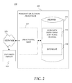
FIG. 2 shows porosity detection processor 105 of FIG. 1 in more detail. As shown in FIG. 2, porosity detection processor 105 may include a processing unit 225 and a memory 230. Memory 230 may include a porosity detection software module 235 and a database 240. While executing on processing unit 225, porosity detection software module 235 may perform processes for providing porosity detection, including, for example, one or more method 300 stages described below with respect to FIG. 3.
Porosity detection processor 105 (“the processor”) included in system 100 may be implemented using a personal computer, network computer, mainframe, or other similar microcomputer-based workstation. The processor may though comprise any type of computer operating environment, such as hand-held devices, multiprocessor systems, microprocessor-based or programmable sender electronic devices, minicomputers, mainframe computers, and the like. The processor may also be practiced in distributed computing environments where tasks are performed by remote processing devices. Furthermore, the processor may comprise a mobile terminal, such as a smart phone, a cellular telephone, a cellular telephone utilizing wireless application protocol (WAP), personal digital assistant (PDA), intelligent pager, portable computer, a hand held computer, a conventional telephone, or a facsimile machine. The aforementioned systems and devices are exemplary and the processor may comprise other systems or devices.
Network 115 may comprise, for example, a local area network (LAN) or a wide area network (WAN). When a LAN is used as network 115, a network interface located at any of the processors may be used to interconnect any of the processors. When network 115 is implemented in a WAN networking environment, such as the Internet, the processors may typically include an internal or external modem (not shown) or other means for establishing communications over the WAN. Further, in utilizing network 115, data sent over network 115 may be encrypted to insure data security by using known encryption/decryption techniques.
In addition to utilizing a wire line communications system as network 115, a wireless communications system, or a combination of wire line and wireless may be utilized as network 115 in order to, for example, exchange web pages via the Internet, exchange e-mails via the Internet, or for utilizing other communications channels. Wireless can be defined as radio transmission via the airwaves. However, it may be appreciated that various other communication techniques can be used to provide wireless transmission, including infrared line of sight, cellular, microwave, satellite, packet radio, and spread spectrum radio. The processors in the wireless environment can be any mobile terminal, such as the mobile terminals described above. Wireless data may include, but is not limited to, paging, text messaging, e-mail, Internet access and other specialized data applications specifically excluding or including voice transmission. For example, the processors may communicate across a wireless interface such as, for example, a cellular interface (e.g., general packet radio system (GPRS), enhanced data rates for global evolution (EDGE), global system for mobile communications (GSM)), a wireless local area network interface (e.g., WLAN, IEEE 802, WiFi, WiMax), a bluetooth interface, another RF communication interface, and/or an optical interface.
Infrared device 120 may comprise a thermographic camera, comprising a forward looking infrared camera, scanning infrared camera, or infrared detector. Infrared device 120 may connect to porosity detection processor 105 over network 115. Infrared device 120 may form an image using infrared radiation, similar to a common camera that forms an image using visible light. Instead of the 450-750 nanometer range of the visible light camera, infrared device 120 may operate in wavelengths as long as 14,000 nm (i.e. 14 μm).
System 100 may also transmit data by methods and processes other than, or in combination with, network 115. These methods and processes may include, but are not limited to, transferring data via, diskette, flash memory sticks, CD ROM, facsimile, conventional mail, an interactive voice response system (IVR), or via voice over a publicly switched telephone network.
FIG. 3 is a flow chart setting forth general stages involved in a method 300 consistent with embodiments of the invention for providing porosity detection. Method 300 may be implemented using porosity detection processor 105 as described in more detail above with respect to FIG. 2. Ways to implement the stages of method 300 will be described in greater detail below. Method 300 may be implemented using an infrared device (e.g. infrared device 120) coupled to a computer (e.g. porosity detection processor 105) running an image analysis software (e.g. porosity detection software module 235.) As described below, the image analysis software may decode an image and look for flaws.
As shown in FIG. 3, parameters may be initialized (stage 305) and a blank sequence may be created (stage 310.) Porosity detection processor 105 may then look at a casting's infrared image as the casting moves across infrared device 120's field of view. (Stage 315.) As the casting is moving, porosity detection processor 105 may look for flaws. For example, porosity detection processor 105 may first take an average across a predetermined length of the casting. (Stage 315.) A temperature at the casting's edges may be cooler than the casting's middle because there may be more energy in the casting's center than at the edges. A plot comprising a natural temperature profile for the casting from edge to edge may yield a parabola or a Gaussian style curve comprising a averaged temperature profile.
Next, porosity detection processor 105 may find the averaged temperature profile's maximum value. (Stage 315.) The maximum value may comprise the casting's center. A second order polynomial may then be fitted to the profile. (Stage 315.) The second order polynomial's peak may be just below the data's peak. Porosity detection processor 105 may next look at the data's peak as it relates to the created second order polynomial. (Stage 320.) If the data in the region of the second order polynomial's peak is lower than the second order polynomial's peak, then porosity detection processor 105 may indicate that a void has been found in the casting as illustrated and described in more detail below with respect to FIG. 4B. (Stage 325.) This may be because a void in the casting may have less energy than the surrounding material and the temperature at the surface may be less than it would be if there were no void.
FIG. 4A is a sample void-less section temperature profile. As shown in FIG. 4A, a curve 405 may correspond to a natural temperature profile for a casting. A curve 410 may correspond to a polynomial fitted to the natural temperature profile of curve 405. Because a peak value of curve 405 is greater than a peak value of curve 410, this may indicate no void is present in the casting.
FIG. 4B is a temperature profile corresponding to a casting including a void. As shown in FIG. 4B, a curve 415 may correspond to a natural temperature profile for a casting. A curve 420 may correspond to a polynomial fitted to the natural temperature profile of curve 415. Because a peak value of curve 415 is less than a peak value of curve 420, this may indicate that a void is present in the casting. FIG. 5 is a photograph showing a void in a casting detected by embodiments of the invention.
After the current image is analyzed by porosity detection processor 105, a next image may be cued and the aforementioned process may be repeated. (Stage 330.) A counter may be maintained to count the number of flaws present in the casting. (Stage 325.) The resulting data and image frames may be saved for further processing if needed. (Stage 335.)
The following is a code listing for a software example that may be used in conjunction with embodiments of the present invention for porosity detection software module 235. The following is an example, and other software modules may be used.
Option Explicit
Sub Southwire( )
Dim LineProfID As Integer
Dim PeakVal As Single
Dim PeakLocation As Integer
Dim a0 As Single
Dim a1 As Single
Dim a2 As Single
Dim t0 As Double
Dim t1 As Double
Dim t2 As Double
Dim i As Integer
Dim j As Integer
Dim k As Integer
Dim x As Integer
′Dim ProfDat(321) As Single ′Allocate array for the data
Dim LineDat(30) As Single ′Allocate array for the data
Dim Ndata As Integer ′Number of frames in sequence
Dim LastDirectory As String*255
Dim S As String*1
Dim Iname As String*255
Dim Title As String*60
Dim Flaw As String*30
Dim OldX1 As Integer
Dim OldY1 As Integer
Dim OldX2 As Integer
Dim OldY2 As Integer
Dim X1 As Integer
Dim Y1 As Integer
Dim X2 As Integer
Dim Y2 As Integer
Dim numbins As Integer
Dim endPts(2) As POINTAPI
Dim stats(10) As Single
Dim S0S1 As Double
Dim S0S2 As Double
Dim S0S3 As Double
Dim S0S4 As Double
Dim S1S1 As Double
Dim S1S2 As Double
Dim S1S3 As Double
Dim S1S4 As Double
Dim S2S2 As Double
Dim S2S3 As Double
Dim S2S4 As Double
Dim S3S2 As Double
Dim S3S3 As Double
Dim DetS As Double
Dim Fit8 As Single
Dim PeakIndex As Integer
Dim TotalFlaws As Integer
Dim Skipped As Integer
Dim PercentFlaws As Single
Dim NoiseLevelPercent As Single
′ Initiallization
S0S1 = 2312
S0S2 = 25432
S0S3 = 314432
S0S4 = 4145416
S1S1 = 18496
S1S2 = 203456
S1S3 = 2515456
S1S4 = 33163328
S2S2 = 2238016
S2S3 = 27670016
S2S4 = 364796608
S3S3 = 342102016
DetS = 53767872
TotalFlaws = 0
NoiseLevelPercent = 0.009 ′ 0.01 = 1% noise, 0.05= 5% noise, etc.
′************************************** Read Last Used Values for
′************************************** x1, y1, x2, y2
Open ″C:\IPWin4\SouthwireTemp.txt″ For Input As #1
Input #1, Last Directory, OldX1, OldY1, OldX2, OldY2
Close #1
′LastDirectory= ″C:\IPWIN4\Images\Feb 8\″
′OldX1 = 60
′OldY1 = 60
′OldX2 = 80
′OldY2 = 239
ret = IpOutputClear( )
ret = IpOutputShow(1)
ret = IpStGetName(″Select Sequence″,LastDirectory,″*.FTS″,Iname)
If ret = 0 Then GoTo StopEarly
ret = IpWsLoad(Iname, ″FTS″)
ret = IpDrShow(1)
ret = IpDrSet(DR_BEST, 0, IPNULL)
ret = IpSeqSet(SEQ_ACTIVEFRAME, 0)
i=255
While S < > ″\″
i=i−1
s = Mid$(Iname, i, 1)
′If s< >″″ Then ret = IpOutput(″i = ″ + Str$(i) + ″ S = ″ + S$+
Chr$(13) + Chr$(10))
Wend
LastDirectory = Left$(Iname, i)
′ShortLastDirectory = Left(Iname, i−1)
x=255
While S < > ″.″
x = x − 1
If X<1 Then
IpOutput(″x = ″ + Str$(x) + ″ i = ″ + Str(i) + Chr$(13) +
Chr$(10))
GoTo StopEarly
End If
S = Mid$(Iname, x, 1)
Wend
′ret = IpOutput(″x = ″ + Str$(x) + ″ i = ″ + Str(i) + Chr$(13) +
Chr$(10))
x = x − i − 1
Title = Mid$(Iname, i+1,x)
ret = IpSeqGet(SEQ_NUMFRAMES, Ndata)
LineProfID = IpProfCreate( )
ret = IpProfSetAttr(LINETYPE, THICKVERT)
ret = IpProfLineMove(OldX1, OldY1, OldX2, OldY2)
If MsgBox(″Please adjust the position of the line. Then press
OK″,vbOkCancel) = vbCancel Then End
ret = IpProfGet(GETPOINTS, 0, endPts(0))
Open ″C:\IPWin4\SouthwireTemp.txt″ For Output As #1
Write#1, Last Directory, endPts(0).x, endPts(0).y, endPts(1).x, endPts(1).y
Close#1
ret = IpOutput(Trim$(Title) + Chr$(13) + Chr$(10))
ret = IpOutput(Chr$(13) + Chr$(10))
ret = IpOutput(″Coordinates: x1= ″+ Trim(Str(endPts(0).x))+″ y1=
″+Trim(Str(endPts(0).y))+″ x2= ″+Trim(Str(endPts(1).x))+″ y2=
″+Trim(Str(endPts(1 ).y)) + Chr$(13) + Chr$(10))
ret = IpOutput(″Image# Flaw?″ + Chr$(13) + Chr$(10))
numbins = endPts(1).y−endPts(0).y + 1
ReDim profdat(numbins) As Single
′ret = IpOutput(″Numbibs=″+Str(numbins) + Chr$(13) + Chr$(10))
′*******************************************
′*
′* Read Data and Re-index
′*
′*******************************************
For i=0 To Ndata−1
ret = IpProfGet(GETVALUES, numbins, profdat(0))
ret = IpProfGet(GETSTATS, 0, stats(0))
PeakVal = stats(4)
PeakLocation =0
j=0
Do
j=j+1
If profdat(j)>14000 Then
Flaw=″Skipped Due to Noise″
Skipped = Skipped + 1
GoTo SkipFrame
End If
If profdat(j)=PeakVal Then PeakLocation = j
Loop While PeakLocation = 0
For j=To 16
k=PeakLocation−8+j
LineDat(j) = ProfDat(k)
′ipoutput(Trim(Str(LineDat(j)))+ Chr$(13)+30Chr$(10))
Next j
′*******************************************
′*
′* Second Order Polynomial Fit Routine
′*
′*******************************************
T0=0
T1=0
T2=0
For k=0 To 16
T0=T0+LineDat(k)
T1=T1+LineDat(k)*k
T2=T2+LineDat(k)*k{circumflex over ( )}2
Next k
a0=(t0*S2S4+t2*s1s3+t1*s2s3−s2s2*t2−s1s4*t1−s3s3*t0)/DetS
a1=(t1*s0s4+t0*s2s3+t2*s1s2−t1*s2s2−t2*s0s3−t0*s1s4)/DetS
a2=(t2*s0s2+t1*s1s2+t0*s1s3−t0*s2s2−t1*s0s3−t2*s1s1)/DetS
PeakIndex = Int(−a1/(2*a2))
If ((PeakIndex<0) Or (PeakIndex>17)) Then
Flaw=″Skipped Due to Bad Fit″
Skipped = Skipped + 1
GoTo SkipFrame
End If
′ret = IpOutput(Trim(Str(PeakIndex))+″ ″ + Chr$(13) + Chr$(10))
Fit8=a0+a1*PeakIndex+a2*PeakIndex{circumflex over ( )}2
If (LineDat(PeakIndex)−((1−NoiseLevelPercent)*Fit8))<0 Then
Flaw=″YES″
Total Flaws=Total Flaws+1
Else
Flaw=″NO″
End If
SkipFrame:
ret = IpOutput(Trim(Str(i))+″ ″ + Flaw + Chr$(13) + Chr$(10))
′ret = IpOutput(″PeakIndex = ″+Trim(Str(PeakIndex))+″ ″ + Flaw +
Chr$(13) + Chr$(10))
′ret = IpOutput(″LineDat−F8 = ″+Trim(Str(LineDat(PeakIndex)−Fit8))+
Chr$(13) + Chr$(10))
′ret = IpOutput(″=″+Trim(Str(a0))+″+″+Trim(Str(a1))+
″*x+″+Trim(Str(a2))+″*x{circumflex over ( )}2″+ Chr$(13) + Chr$(10))
′ret = IpOutput(Chr$(13) + Chr$(10))
ret = IpSeqPlay(SEQ_NEXT)
Next i
ret = IpOutput(″RESULTS: ″+Trim(Str(TotalFlaws))+″ Flaws out of ″ +
Trim(Str(NData−Skipped))+″ images″ + Chr$(13) + Chr$(10))
PercentFlaws = Int(((TotalFlaws*100)/(NData−Skipped))*100)/100
ret = IpOutput(″Percent of Images with Flaws = ″+Trim(Str(PercentFlaws))+″
%″)
StopEarly:
End Sub
Consistent with embodiments of the invention, a computer executing a software algorithm may be used to detect a depression in a temperature profile. First, the temperature profile may be smoothed slightly to eliminate systematic noise. Next, the center of the temperature profile may be extracted. A polynomial (e.g. an nth order polynomial) may be fitted to extracted data. An algorithm used to fit the polynomial may guarantee that the peak of the fitted curve may be below the peak of the actual data. Next, residuals may be calculated by subtracting the fitted curve from the actual data. If there is a dip at the center, then the residuals in the center may be less than zero. The software algorithm executing on the computer may then make a decision based on a sign of the residuals. For example, residuals less than zero may indicate bar porosity. Residuals above zero may indicate no porosity. The magnitude of the residuals may then be used to classify a size of a detected defect.
OPERATIONAL EXAMPLE
Table 1 summarizes data that was obtained using a process consistent with embodiments of the invention. Table 1 shows that, at 45 feet per minute (FPM), test 1 measured 4.5% flaws using a micrometer after bars were cooled and cut open. Consistent with embodiments of the invention, the IR process measured 5.6% flaws. The difference of 1.1% may be attributed to noise in the process and IR method. 45 FPM test 2 shows a difference of 0.5% between the IR and measured flaws. When the casting rate was increased to the 50 and 52 FPM, the IR and measured flaws increased dramatically. The negative difference for the 50 FPM may be attributed to an error in the frame rate of the camera over counting flaws. These errors needed to be corrected and a system designed for permanent installation on the casting machine.
TABLE 1
Correlation Data for
Selected Production Rates
Flaws Detected
Bar Speed1 Measured Flaws2 By IR Imaging3 Difference4
45 Test 1 4.5% 5.6% 1.1
45 Test 2 4.5% 5.0% 0.5
50 17.2% 15.3% −1.9
52 15.2% 14.8% 0.4
1Speed of casting machine in ft/min.
2Flaws as measured in the bar with a micrometer.
3Output of the IR flaw detection system.
4Difference = IR − Measured
Table 2 shows the effect of different noise figures on the difference between the IR measured flaws consistent with embodiments of the invention and the actual flaws as a function of the flaw size. Independent of the casting rate, a noise factor of 0.012 may be used to look for flaws above 0.003 in2, 0.0095 to look for flaws above 0.0019 in2, and 0.0078 to look for flaws above 0.0007 in2.
TABLE 2
Noise Corrected Data
% Difference for Different Speeds and Flaw Sizes
Flaw Size (in2) Large 0.003 Medium 0.0019 Small 0.0007
Noise Factor 0.012 0.0095 0.0078
45 FPM1 −0.2 −1.2 −1.0
50 FRM −0.4 −1.8 −4.9
52 FPM 0.0 3.4 5.6
1Feet per minute
Consistent with embodiments of the invention, the size of detected flaws may be classified. The flaws may be grouped, for example, into three size groups; small, medium, and large. The actual size of flaws that correspond to respective size groups may be dependent on, for example, an individual rod mill. To classify a flaw, the magnitude of a residual that indicated the flaw may be analyzed and used as the classification criteria. Table 3 summarizes data that may be used to define, for example, the small, medium, and large flaw size groups. At 47, 50, and 52 FPM, the total flaws counted may be broken up into the three size categories. Next the residual magnitudes may be split, for example, into the following:
    • Below 80=Small
    • Above 80 and below 140=Medium
    • Above 140=Large
These criteria may be used to calculate a percentage of the total flaws that each size category may have contributed. In Table 3, at 44 FPM, 0.6% of the production had flaws, and of that 0.6%, 100% were small flaws. At 47 FPM, 5.6% of production had flaws, and of that 5.6%, 86% were small, 13% were medium, and 1% was large. The flaws at 52 FPM increased to 7%, of which, 73% were small, 23% were medium, and 4% were large. “Percent production with flaws” may be defined as the percentage of inches, centimeters, etc. in a production that a flaw may have been detected. For example if the value is 10%, then when 100 inches of sample bar is analyzed, 10 inches of the sample may contain flaws. This may not indicate, however, that there are 10 inches of flaw area in the sample.
TABLE 3
Flaw Size Distribution
Avg Max Flaw % Prod Avg %
Flaw Flaw Per with Res- % Med- %
Speed Size Size Inch Flaws idue Small ium Large
44 0.0026 0.019 0.14 0.6 80 100 0 0
FPM
47 0.008 0.216 0.18 5.6 100 86 13 1
FPM
52 0.006 0.240 0.54 7 140 73 23 4
FPM
Generally, consistent with embodiments of the invention, program modules may include routines, programs, components, data structures, and other types of structures that may perform particular tasks or that may implement particular abstract data types. Moreover, embodiments of the invention may be practiced with other computer system configurations, including hand-held devices, multiprocessor systems, microprocessor-based or programmable consumer electronics, minicomputers, mainframe computers, and the like. Embodiments of the invention may also be practiced in distributed computing environments where tasks are performed by remote processing devices that are linked through a communications network. In a distributed computing environment, program modules may be located in both local and remote memory storage devices.
Furthermore, embodiments of the invention may be practiced in an electrical circuit comprising discrete electronic elements, packaged or integrated electronic chips containing logic gates, a circuit utilizing a microprocessor, or on a single chip containing electronic elements or microprocessors. Embodiments of the invention may also be practiced using other technologies capable of performing logical operations such as, for example, AND, OR, and NOT, including but not limited to mechanical, optical, fluidic, and quantum technologies. In addition, embodiments of the invention may be practiced within a general purpose computer or in any other circuits or systems.
Embodiments of the invention, for example, may be implemented as a computer process (method), a computing system, or as an article of manufacture, such as a computer program product or computer readable media. The computer program product may be a computer storage media readable by a computer system and encoding a computer program of instructions for executing a computer process. The computer program product may also be a propagated signal on a carrier readable by a computing system and encoding a computer program of instructions for executing a computer process. Accordingly, the present invention may be embodied in hardware and/or in software (including firmware, resident software, micro-code, etc.). In other words, embodiments of the present invention may take the form of a computer program product on a computer-usable or computer-readable storage medium having computer-usable or computer-readable program code embodied in the medium for use by or in connection with an instruction execution system. A computer-usable or computer-readable medium may be any medium that can contain, store, communicate, propagate, or transport the program for use by or in connection with the instruction execution system, apparatus, or device.
The computer-usable or computer-readable medium may be, for example but not limited to, an electronic, magnetic, optical, electromagnetic, infrared, or semiconductor system, apparatus, device, or propagation medium. More specific computer-readable medium examples (a non-exhaustive list), the computer-readable medium may include the following: an electrical connection having one or more wires, a portable computer diskette, a random access memory (RAM), a read-only memory (ROM), an erasable programmable read-only memory (EPROM or Flash memory), an optical fiber, and a portable compact disc read-only memory (CD-ROM). Note that the computer-usable or computer-readable medium could even be paper or another suitable medium upon which the program is printed, as the program can be electronically captured, via, for instance, optical scanning of the paper or other medium, then compiled, interpreted, or otherwise processed in a suitable manner, if necessary, and then stored in a computer memory.
Embodiments of the present invention, for example, are described above with reference to block diagrams and/or operational illustrations of methods, systems, and computer program products according to embodiments of the invention. The functions/acts noted in the blocks may occur out of the order as shown in any flowchart. For example, two blocks shown in succession may in fact be executed substantially concurrently or the blocks may sometimes be executed in the reverse order, depending upon the functionality/acts involved.
While certain embodiments of the invention have been described, other embodiments may exist. Furthermore, although embodiments of the present invention have been described as being associated with data stored in memory and other storage mediums, data can also be stored on or read from other types of computer-readable media, such as secondary storage devices, like hard disks, floppy disks, or a CD-ROM, a carrier wave from the Internet, or other forms of RAM or ROM. Further, the disclosed methods' stages may be modified in any manner, including by reordering stages and/or inserting or deleting stages, without departing from the invention.
While the specification includes examples, the invention's scope is indicated by the following claims. Furthermore, while the specification has been described in language specific to structural features and/or methodological acts, the claims are not limited to the features or acts described above. Rather, the specific features and acts described above are disclosed as example for embodiments of the invention.

Claims (51)

What is claimed is:
1. A system for providing porosity detection, the system comprising:
a memory storage; and
a processing unit coupled to the memory storage, wherein the processing unit is operative to:
fit a mathematical function to a heat signature profile of an object;
compare the heat signature profile to the fitted mathematical function; and
indicate that a defect exists in the object when, in response to the comparison, a peak value of the heat signature profile is less than a peak value of the mathematical function.
2. The system of claim 1, further comprising the processing unit being operative to receive, from an infrared device, data corresponding to the heat signature for the object.
3. The system of claim 1, further comprising the processing unit being operative to, in response to the indication that the defect exists in the object, slow down a casting process associated with the object.
4. The system of claim 1, wherein the processing unit being operative to fit the mathematical function to the heat signature profile comprises the processing unit being operative to fit the mathematical function comprising a polynomial.
5. The system of claim 1, wherein the processing unit being operative to fit the mathematical function to the heat signature profile comprises the processing unit being operative to fit the mathematical function comprising a second order polynomial.
6. The system of claim 1, wherein the processing unit being operative to fit the mathematical function to the heat signature profile comprises the processing unit being operative to fit the mathematical function comprising a second order mathematical function.
7. The system of claim 1, wherein the processing unit being operative to create the heat signature profile for the object comprises the processing unit being operative to create the heat signature profile comprising a natural temperature profile for the object.
8. The system of claim 1, wherein the object comprises a bar that is cast in a continuous casting process.
9. The system of claim 1, further comprising the processing unit being operative to create the heat signature profile for the object.
10. The system of claim 9, wherein the processing unit being operative to create the heat signature profile for the object comprises the processing unit being operative to create the heat signature profile for the object from a first edge of the object to a second edge of the object.
11. The system of claim 1, wherein the object comprises a casting.
12. The system of claim 11, wherein the casting comprises one of the following: a copper casting and an aluminum casting.
13. The system of claim 1, wherein the defect comprises a void.
14. A method for providing porosity detection, the method comprising:
fitting a mathematical function to a heat signature profile of an object;
comparing, by a processor, the heat signature profile to the fitted mathematical function; and
indicating that a defect exists in the object when, in response to the comparison, a peak value of the heat signature profile is less than a peak value of the mathematical function.
15. The method of claim 14, further comprising, in response to indicating that the defect exists in the object, slowing down a casting process associated with the object.
16. The method of claim 14, further comprising creating the heat signature profile for the object.
17. The method of claim 16, wherein creating the heat signature profile for the object comprises creating the heat signature profile for the object wherein the object comprises a bar that is cast in a continuous casting process.
18. The method of claim 14, wherein the object comprises a casting.
19. The method of claim 14, wherein indicating that the defect exists comprises indicating that a void exists.
20. A non-transitory computer-readable storage medium device which stores a set of instructions which when executed performs a method for providing porosity detection, the method executed by the set of instructions comprising:
fitting a mathematical function to a heat signature profile of an object;
comparing the heat signature profile to the fitted mathematical function; and
indicating that a defect exists in the object when, in response to the comparison, a peak value of the heat signature profile is less than a peak value of the mathematical function.
21. The non-transitory computer-readable storage of claim 20, further comprising, in response to indicating that the defect exists in the object, slowing down a casting process associated with the object.
22. The non-transitory computer-readable storage of claim 20, wherein the object comprises a casting.
23. The non-transitory computer-readable storage of claim 20, wherein indicating that the defect exists comprises indicating that a void exists.
24. The non-transitory computer-readable storage of claim 20, further comprising creating the heat signature profile for the object.
25. The non-transitory computer-readable storage of claim 24, wherein creating the heat signature profile for the object comprises creating the heat signature profile for the object wherein the object comprises a bar that is cast in a continuous casting process.
26. A system for providing porosity detection, the system comprising:
a memory storage; and
a processing unit coupled to the memory storage, wherein the processing unit is operative to:
fit a mathematical function to a heat signature profile of an object;
compare the heat signature profile to the fitted mathematical function; and
indicate that a defect does not exist in the object when, in response to the comparison, a peak value of the heat signature profile is one of the following:
greater than a peak value of the mathematical function and equal to a peak value of the mathematical function.
27. The system of claim 26, further comprising the processing unit being operative to receive, from an infrared device, data corresponding to the heat signature for the object.
28. The system of claim 26, further comprising the processing unit being operative to, in response to the indication that the defect does not exist in the object, speed up a casting process associated with the object.
29. The system of claim 26, wherein the processing unit being operative to fit the mathematical function to the heat signature profile comprises the processing unit being operative to fit the mathematical function comprising a polynomial.
30. The system of claim 26, wherein the processing unit being operative to fit the mathematical function to the heat signature profile comprises the processing unit being operative to fit the mathematical function comprising a second order polynomial.
31. The system of claim 26, wherein the processing unit being operative to fit the mathematical function to the heat signature profile comprises the processing unit being operative to fit the mathematical function comprising a second order mathematical function.
32. The system of claim 26, wherein the processing unit being operative to create the heat signature profile for the object comprises the processing unit being operative to create the heat signature profile comprising a natural temperature profile for the object.
33. The system of claim 26, wherein the object comprises a bar that is cast in a continuous casting process.
34. The system of claim 26, wherein the defect comprises a void.
35. The system of claim 26, further comprising the processing unit being operative to create the heat signature profile for the object.
36. The system of claim 35, wherein the processing unit being operative to create the heat signature profile for the object comprises the processing unit being operative to create the heat signature profile for the object from a first edge of the object to a second edge of the object.
37. The system of claim 26, wherein the object comprises a casting.
38. The system of claim 37, wherein the casting comprises one of the following: a copper casting and an aluminum casting.
39. The system of claim 26, wherein the object comprises a bar that is cast in a continuous casting process.
40. A method for providing porosity detection, the method comprising:
fitting a mathematical function to a heat signature profile of an object;
comparing, by a processor, the heat signature profile to the fitted mathematical function; and
indicating that a defect does not exist in the object when, in response to the comparison, a peak value of the heat signature profile is one of the following: greater than a peak value of the mathematical function and equal to a peak value of the mathematical function.
41. The method of claim 40, further comprising, in response to indicating that the defect does not exist in the object, speeding up a casting process associated with the object.
42. The method of claim 40, wherein indicating that the defect does not exist comprises indicating that a void does not exist.
43. The method of claim 40, further comprising creating the heat signature profile for the object.
44. The method of claim 43, wherein creating the heat signature profile for the object comprises creating the heat signature profile for the object wherein the object comprises a bar that is cast in a continuous casting process.
45. The method of claim 40, wherein the object comprises a casting.
46. A non-transitory computer-readable storage medium device which stores a set of instructions which when executed performs a method for providing porosity detection, the method executed by the set of instructions comprising:
fitting a mathematical function to a heat signature profile of an object;
comparing the heat signature profile to the fitted mathematical function; and
indicating that a defect does not exist in the object when, in response to the comparison, a peak value of the heat signature profile is one of the following: greater than a peak value of the mathematical function and equal to a peak value of the mathematical function.
47. The non-transitory computer-readable storage of claim 46, further comprising, in response to indicating that the defect does not exist in the object, speeding up a casting process associated with the object.
48. The non-transitory computer-readable storage of claim 46, wherein the object comprises a casting.
49. The non-transitory computer-readable storage of claim 46, wherein indicating that the defect does not exist comprises indicating that a void does not exist.
50. The non-transitory computer-readable storage of claim 46, further comprising creating the heat signature profile for the object.
51. The non-transitory computer-readable storage of claim 50, wherein creating the heat signature profile for the object comprises creating the heat signature profile for the object wherein the object comprises a bar that is cast in a continuous casting process.
US13/611,228 2008-03-17 2012-09-12 Porosity detection Active US8991472B2 (en)

Priority Applications (1)

Application Number Priority Date Filing Date Title
US13/611,228 US8991472B2 (en) 2008-03-17 2012-09-12 Porosity detection

Applications Claiming Priority (4)

Application Number Priority Date Filing Date Title
US3707708P 2008-03-17 2008-03-17
US14850309P 2009-01-30 2009-01-30
US12/405,288 US8276645B2 (en) 2008-03-17 2009-03-17 Porosity detection
US13/611,228 US8991472B2 (en) 2008-03-17 2012-09-12 Porosity detection

Related Parent Applications (1)

Application Number Title Priority Date Filing Date
US12/405,288 Continuation US8276645B2 (en) 2008-03-17 2009-03-17 Porosity detection

Publications (2)

Publication Number Publication Date
US20130060511A1 US20130060511A1 (en) 2013-03-07
US8991472B2 true US8991472B2 (en) 2015-03-31

Family

ID=40790987

Family Applications (2)

Application Number Title Priority Date Filing Date
US12/405,288 Active 2030-12-25 US8276645B2 (en) 2008-03-17 2009-03-17 Porosity detection
US13/611,228 Active US8991472B2 (en) 2008-03-17 2012-09-12 Porosity detection

Family Applications Before (1)

Application Number Title Priority Date Filing Date
US12/405,288 Active 2030-12-25 US8276645B2 (en) 2008-03-17 2009-03-17 Porosity detection

Country Status (8)

Country Link
US (2) US8276645B2 (en)
EP (1) EP2257401B1 (en)
JP (2) JP5341977B2 (en)
KR (1) KR101296465B1 (en)
CN (1) CN102015161B (en)
ES (1) ES2526554T3 (en)
HK (1) HK1150811A1 (en)
WO (1) WO2009117380A1 (en)

Families Citing this family (5)

* Cited by examiner, † Cited by third party
Publication number Priority date Publication date Assignee Title
US7941906B2 (en) * 2007-12-31 2011-05-17 Schlumberger Technology Corporation Progressive cavity apparatus with transducer and methods of forming and use
WO2009117380A1 (en) 2008-03-17 2009-09-24 Rundquist Victor F Porosity detection
EP2951989A4 (en) * 2013-01-29 2016-09-28 Opgal Optronic Ind Ltd Universal serial bus (usb) thermal imaging camera kit
WO2014144142A2 (en) * 2013-03-15 2014-09-18 Mu Optics, Llc Thermographic camera accessory for personal electronics
CN106424609A (en) * 2016-09-19 2017-02-22 天津瑞盈机电设备有限公司 Iron liquid quality control system

Citations (34)

* Cited by examiner, † Cited by third party
Publication number Priority date Publication date Assignee Title
JPS5764459A (en) 1980-10-06 1982-04-19 Furukawa Electric Co Ltd:The Continuous casting method for copper or copper alloy
JPS58187253A (en) 1982-04-27 1983-11-01 Nippon Steel Corp Method for detecting abnormality and evaluating surface of ingot in continuous casting
JPS6054256A (en) 1983-08-31 1985-03-28 Sumitomo Heavy Ind Ltd Method for diagnosing abnormality of continuous casting machine
JPS6330164A (en) 1986-07-22 1988-02-08 Kubota Ltd Detecting method for casting defect in continuous casting
US5103892A (en) * 1990-02-28 1992-04-14 Asarco Incorporated Continuous casting of discrete shapes
US5125450A (en) * 1990-05-07 1992-06-30 Electrovert Ltd. Method of and system for controlling flow of molten liquid to cast metal alloys
US5144838A (en) 1989-10-04 1992-09-08 Iwatsu Electric Co., Ltd. Defect detecting method and apparatus
US5179860A (en) 1989-10-04 1993-01-19 Iwatsu Electric Co., Ltd. Defect detecting method and apparatus
US5292195A (en) * 1992-09-09 1994-03-08 Martin Marietta Corporation Thermographic evaluation technique
JPH0890184A (en) 1994-09-19 1996-04-09 Nippon Steel Corp Device and method for preventing flaw on cast slab
US5654977A (en) * 1995-02-02 1997-08-05 Teledyne Industries Inc. Method and apparatus for real time defect inspection of metal at elevated temperature
US5974889A (en) * 1998-01-02 1999-11-02 General Electric Company Ultrasonic multi-transducer rotatable scanning apparatus and method of use thereof
US6013915A (en) 1998-02-10 2000-01-11 Philip Morris Incorporated Process control by transient thermography
US6097019A (en) 1990-07-11 2000-08-01 International Business Machines Corporation Radiation control system
US6150645A (en) 1990-07-11 2000-11-21 International Business Machines Corporation Radiation control system
CN1341908A (en) 2001-09-03 2002-03-27 华南理工大学 Automatic analysis and identification device of internal defect in cast and its analysis and identification method
US6394646B1 (en) 1999-04-16 2002-05-28 General Electric Company Method and apparatus for quantitative nondestructive evaluation of metal airfoils using high resolution transient thermography
JP2002543277A (en) 1999-04-27 2002-12-17 ペシネイ レナリュ Improved method and apparatus for degassing and inclusion separation of molten metal bath by bubble injection
US6595684B1 (en) * 1999-11-03 2003-07-22 Northrop Grumman Corporation System and method for evaluating a structure
US6610953B1 (en) * 1998-03-23 2003-08-26 University Of Arkansas Item defect detection apparatus and method
US20050023468A1 (en) * 2003-07-29 2005-02-03 Kozo Saito Systems and methods for inspecting coatings
US20050173820A1 (en) 2001-03-21 2005-08-11 Signature Control Systems Process and apparatus for improving and controlling the curing of natural and synthetic moldable compounds
US7045029B2 (en) 2001-05-31 2006-05-16 Kimberly-Clark Worldwide, Inc. Structured material and method of producing the same
US7118639B2 (en) 2001-05-31 2006-10-10 Kimberly-Clark Worldwide, Inc. Structured material having apertures and method of producing the same
EP1717754A2 (en) 2005-04-28 2006-11-02 YXLON International X-Ray GmbH Method for classifying casting defects within the scope of an X-ray analysis
US7159641B2 (en) 2000-05-12 2007-01-09 Nippon Steel Corporation Cooling drum for thin slab continuous casting, processing method and apparatus thereof, and thin slab and continuous casting method thereof
JP2007167871A (en) 2005-12-19 2007-07-05 Nippon Steel Corp Apparatus and method for determining operating state of working surfaces of casting mold or casting die, method for operating casting mold or casting die, computer program, and recording medium readable by computer
US20080035298A1 (en) 2006-08-11 2008-02-14 Rmi Titanium Company Method and apparatus for temperature control in a continuous casting furnace
US20080083478A1 (en) 2002-08-29 2008-04-10 Kouji Yamada High strength aluminum alloy casting and method of production of same
US7421370B2 (en) * 2005-09-16 2008-09-02 Veeco Instruments Inc. Method and apparatus for measuring a characteristic of a sample feature
US7567740B2 (en) 2003-07-14 2009-07-28 Massachusetts Institute Of Technology Thermal sensing fiber devices
US20090228230A1 (en) * 2008-03-06 2009-09-10 General Electric Company System and method for real-time detection of gas turbine or aircraft engine blade problems
US20090229779A1 (en) 2008-03-17 2009-09-17 Southwire Company Porosity Detection
US7886807B2 (en) 2007-06-15 2011-02-15 Die Therm Engineering L.L.C. Die casting control method

Family Cites Families (3)

* Cited by examiner, † Cited by third party
Publication number Priority date Publication date Assignee Title
JPH08164476A (en) * 1994-12-15 1996-06-25 Hitachi Metals Ltd Casting plan display system
EP1148333A1 (en) * 2000-02-05 2001-10-24 YXLON International X-Ray GmbH Automatic casting defects recognition in specimens
CN101045255A (en) * 2006-03-27 2007-10-03 宝山钢铁股份有限公司 Continuous casting bleed-out quick response method, and device therefor

Patent Citations (40)

* Cited by examiner, † Cited by third party
Publication number Priority date Publication date Assignee Title
JPS5764459A (en) 1980-10-06 1982-04-19 Furukawa Electric Co Ltd:The Continuous casting method for copper or copper alloy
JPS58187253A (en) 1982-04-27 1983-11-01 Nippon Steel Corp Method for detecting abnormality and evaluating surface of ingot in continuous casting
JPS6054256A (en) 1983-08-31 1985-03-28 Sumitomo Heavy Ind Ltd Method for diagnosing abnormality of continuous casting machine
JPS6330164A (en) 1986-07-22 1988-02-08 Kubota Ltd Detecting method for casting defect in continuous casting
US5144838A (en) 1989-10-04 1992-09-08 Iwatsu Electric Co., Ltd. Defect detecting method and apparatus
US5179860A (en) 1989-10-04 1993-01-19 Iwatsu Electric Co., Ltd. Defect detecting method and apparatus
US5103892A (en) * 1990-02-28 1992-04-14 Asarco Incorporated Continuous casting of discrete shapes
US5125450A (en) * 1990-05-07 1992-06-30 Electrovert Ltd. Method of and system for controlling flow of molten liquid to cast metal alloys
US6150645A (en) 1990-07-11 2000-11-21 International Business Machines Corporation Radiation control system
US6097019A (en) 1990-07-11 2000-08-01 International Business Machines Corporation Radiation control system
US5292195A (en) * 1992-09-09 1994-03-08 Martin Marietta Corporation Thermographic evaluation technique
JPH0890184A (en) 1994-09-19 1996-04-09 Nippon Steel Corp Device and method for preventing flaw on cast slab
US5654977A (en) * 1995-02-02 1997-08-05 Teledyne Industries Inc. Method and apparatus for real time defect inspection of metal at elevated temperature
US5974889A (en) * 1998-01-02 1999-11-02 General Electric Company Ultrasonic multi-transducer rotatable scanning apparatus and method of use thereof
US6690016B1 (en) 1998-02-10 2004-02-10 Philip Morris Incorporated Process control by transient thermography
US6013915A (en) 1998-02-10 2000-01-11 Philip Morris Incorporated Process control by transient thermography
US6610953B1 (en) * 1998-03-23 2003-08-26 University Of Arkansas Item defect detection apparatus and method
US6394646B1 (en) 1999-04-16 2002-05-28 General Electric Company Method and apparatus for quantitative nondestructive evaluation of metal airfoils using high resolution transient thermography
JP2002543277A (en) 1999-04-27 2002-12-17 ペシネイ レナリュ Improved method and apparatus for degassing and inclusion separation of molten metal bath by bubble injection
US6595684B1 (en) * 1999-11-03 2003-07-22 Northrop Grumman Corporation System and method for evaluating a structure
US7159641B2 (en) 2000-05-12 2007-01-09 Nippon Steel Corporation Cooling drum for thin slab continuous casting, processing method and apparatus thereof, and thin slab and continuous casting method thereof
US20050173820A1 (en) 2001-03-21 2005-08-11 Signature Control Systems Process and apparatus for improving and controlling the curing of natural and synthetic moldable compounds
US7167773B2 (en) 2001-03-21 2007-01-23 Signature Control Systems Process and apparatus for improving and controlling the curing of natural and synthetic moldable compounds
US7045029B2 (en) 2001-05-31 2006-05-16 Kimberly-Clark Worldwide, Inc. Structured material and method of producing the same
US7118639B2 (en) 2001-05-31 2006-10-10 Kimberly-Clark Worldwide, Inc. Structured material having apertures and method of producing the same
CN1341908A (en) 2001-09-03 2002-03-27 华南理工大学 Automatic analysis and identification device of internal defect in cast and its analysis and identification method
US20080083478A1 (en) 2002-08-29 2008-04-10 Kouji Yamada High strength aluminum alloy casting and method of production of same
US7567740B2 (en) 2003-07-14 2009-07-28 Massachusetts Institute Of Technology Thermal sensing fiber devices
US20050023468A1 (en) * 2003-07-29 2005-02-03 Kozo Saito Systems and methods for inspecting coatings
JP2006305635A (en) 2005-04-28 2006-11-09 Yxlon Internatl X-Ray Gmbh Method for classifying cast defect in framework of x-ray analysis
EP1717754A2 (en) 2005-04-28 2006-11-02 YXLON International X-Ray GmbH Method for classifying casting defects within the scope of an X-ray analysis
US7421370B2 (en) * 2005-09-16 2008-09-02 Veeco Instruments Inc. Method and apparatus for measuring a characteristic of a sample feature
JP2007167871A (en) 2005-12-19 2007-07-05 Nippon Steel Corp Apparatus and method for determining operating state of working surfaces of casting mold or casting die, method for operating casting mold or casting die, computer program, and recording medium readable by computer
US20080035298A1 (en) 2006-08-11 2008-02-14 Rmi Titanium Company Method and apparatus for temperature control in a continuous casting furnace
US7617863B2 (en) 2006-08-11 2009-11-17 Rti International Metals, Inc. Method and apparatus for temperature control in a continuous casting furnace
US7886807B2 (en) 2007-06-15 2011-02-15 Die Therm Engineering L.L.C. Die casting control method
US20090228230A1 (en) * 2008-03-06 2009-09-10 General Electric Company System and method for real-time detection of gas turbine or aircraft engine blade problems
US20090229779A1 (en) 2008-03-17 2009-09-17 Southwire Company Porosity Detection
JP2011514261A (en) 2008-03-17 2011-05-06 サウスワイヤー カンパニー Porosity detection
US8276645B2 (en) * 2008-03-17 2012-10-02 Southwire Company Porosity detection

Non-Patent Citations (13)

* Cited by examiner, † Cited by third party
Title
Albert J. Phillips, "The Separation of Gases from Molten Metals," Institute of Metals, pp. 20-49, Date Unknown.
Chia et al., "The Metallurgy of Southwire's Continuous Rod," Journal of Metals, vol. 33, No. 2, Feb. 1981, pp. 68-74.
Chinese First Office Action dated Jul. 17, 2012 cited in Application No. 200980116712.7, 10 pgs.
Chinese Second Office Action dated Mar. 14, 2013 cited in Application No. 200980116712.7, 13 pgs.
Chinese Third Office Action dated Jul. 12, 2013 cited in Application No. 200980116712.7, 7 pgs.
European Office Action dated Mar. 25, 2013 cited in Application No. 09 722 845.6, 4 pgs.
International Search Report dated Jul. 14, 2009 cited in Application No. PCT/US2009/037344.
Japanese Notification of Reasons of Refusal dated Apr. 22, 2014 cited in Application No. 2013-165639, 5 pgs.
Japanese Office Action dated Feb. 26, 2013 cited in Application No. 2011-500889, 6 pgs.
Kiran Manchiraju et al., "Southwire Continuous Casting Technology and Introduction to Bar Porosity Detection Infrared System," (Proprietary and Confidential property of Southwire Company), Jan. 27, 2009, pp. 1-18.
Korean Official Notice of Preliminary Rejection dated Dec. 4, 2012 cited in Application No. 10-2010-7022880, 5 pgs.
Ronald D. Adams, Southwire Company Metallurgical Laboratory, MP-4072, An Investigation of Copper Cast Bar Scale Formation Rate, pp. 1-11, Date Unknown.
Ronald D. Adams, Southwire Metallurgical Laboratory, MP-3760, Examination of Gross Centerline Porosity in 5 Sq. In. Copper Bar, pp. 1-6, Date Unknown.

Also Published As

Publication number Publication date
WO2009117380A1 (en) 2009-09-24
HK1150811A1 (en) 2012-01-13
US8276645B2 (en) 2012-10-02
CN102015161B (en) 2014-01-29
KR20100132035A (en) 2010-12-16
EP2257401B1 (en) 2014-11-26
KR101296465B1 (en) 2013-08-13
US20130060511A1 (en) 2013-03-07
JP2013240833A (en) 2013-12-05
US20090229779A1 (en) 2009-09-17
CN102015161A (en) 2011-04-13
ES2526554T3 (en) 2015-01-13
JP5622904B2 (en) 2014-11-12
EP2257401A1 (en) 2010-12-08
JP2011514261A (en) 2011-05-06
JP5341977B2 (en) 2013-11-13

Similar Documents

Publication Publication Date Title
US8991472B2 (en) Porosity detection
CN109983324B (en) Method and system for quantitative measurement of internal defects in as-cast steel products
JPS61501174A (en) Automatic inspection of hot steel slabs
KR101667471B1 (en) Defect determination device, radiography system, and defect determination method
CN114708935B (en) Crystallizer copper plate quality optimization method and system based on heat conduction performance evaluation
CN116502187B (en) Digital copyright protection system and method based on block chain
Agarwal et al. Knowledge discovery in steel bar rolling mills using scheduling data and automated inspection
CN104335236A (en) Method and apparatus for detecting unauthorized bulk forwarding of sensitive data over a network
CN107204892B (en) Power communication network operation data processing method and device
Pellegrini et al. Successful use case applications of artificial intelligence in the steel industry
Rosenstock et al. Online visualization during open die forging and optimization of pass schedules
US20210268740A1 (en) Methods and Systems for Detection of Impurities in Additive Manufacturing Material
CN112374081A (en) Large-scale conveyer belt surface crack detection method and system
CN114054709B (en) Method, equipment and storage medium for identifying and tracking casting blank
Uyan et al. Foundry data collection and part tracking using additively manufactured digital code direct-part-marking tags
Bao-hua et al. Attribute reduction based on information entropy of approximation boundary accuracy
CN115457164A (en) IDC machine room temperature cloud chart drawing method
KOU et al. SAR Image Segmentation Based on SRADPRO and SCM Model
Lett Solidification Defects In Light Alloy Castings And Solid Freeform Fabricated Stainless Steel Deposits
WO2023204814A1 (en) Dynamic network slicing based resource scheduling for remote real-time robotic adaptive repair
Yoshioka et al. Performance evaluation of sketch schemes on traffic anomaly detection accuracy
JP2018155566A (en) Film inspection system and method of manufacturing film
CN115243257A (en) Authentication system and authentication method for sensing equipment of subway station
CN116805305A (en) Processing method and system for flaw detection image defects and electronic equipment
CN115308232A (en) Material analysis method

Legal Events

Date Code Title Description
AS Assignment

Owner name: BANK OF AMERICA, N.A., AS COLLATERAL AGENT, NORTH CAROLINA

Free format text: SECURITY AGREEMENT;ASSIGNORS:SOUTHWIRE COMPANY, LLC;COLEMAN CABLE, INC.;TECHNOLOGY RESEARCH CORPORATION;REEL/FRAME:032251/0277

Effective date: 20140211

Owner name: BANK OF AMERICA, N.A., AS COLLATERAL AGENT, NORTH

Free format text: SECURITY AGREEMENT;ASSIGNORS:SOUTHWIRE COMPANY, LLC;COLEMAN CABLE, INC.;TECHNOLOGY RESEARCH CORPORATION;REEL/FRAME:032251/0277

Effective date: 20140211

AS Assignment

Owner name: WELLS FARGO BANK, NATIONAL ASSOCIATION, AS COLLATERAL AGENT, GEORGIA

Free format text: GRANT OF SECURITY INTEREST IN PATENT RIGHTS;ASSIGNORS:SOUTHWIRE COMPANY, LLC;COLEMAN CABLE, INC.;TECHNOLOGY RESEARCH CORPORATION;REEL/FRAME:032308/0469

Effective date: 20140211

Owner name: WELLS FARGO BANK, NATIONAL ASSOCIATION, AS COLLATE

Free format text: GRANT OF SECURITY INTEREST IN PATENT RIGHTS;ASSIGNORS:SOUTHWIRE COMPANY, LLC;COLEMAN CABLE, INC.;TECHNOLOGY RESEARCH CORPORATION;REEL/FRAME:032308/0469

Effective date: 20140211

STCF Information on status: patent grant

Free format text: PATENTED CASE

MAFP Maintenance fee payment

Free format text: PAYMENT OF MAINTENANCE FEE, 4TH YEAR, LARGE ENTITY (ORIGINAL EVENT CODE: M1551); ENTITY STATUS OF PATENT OWNER: LARGE ENTITY

Year of fee payment: 4

MAFP Maintenance fee payment

Free format text: PAYMENT OF MAINTENANCE FEE, 8TH YEAR, LARGE ENTITY (ORIGINAL EVENT CODE: M1552); ENTITY STATUS OF PATENT OWNER: LARGE ENTITY

Year of fee payment: 8