US8980435B2 - CMC component, power generation system and method of forming a CMC component - Google Patents
CMC component, power generation system and method of forming a CMC component Download PDFInfo
- Publication number
- US8980435B2 US8980435B2 US13/252,540 US201113252540A US8980435B2 US 8980435 B2 US8980435 B2 US 8980435B2 US 201113252540 A US201113252540 A US 201113252540A US 8980435 B2 US8980435 B2 US 8980435B2
- Authority
- US
- United States
- Prior art keywords
- ceramic
- matrix composite
- foam core
- ceramic matrix
- component
- Prior art date
- Legal status (The legal status is an assumption and is not a legal conclusion. Google has not performed a legal analysis and makes no representation as to the accuracy of the status listed.)
- Active, expires
Links
- 238000010248 power generation Methods 0.000 title claims abstract description 25
- 238000000034 method Methods 0.000 title abstract description 24
- 239000011153 ceramic matrix composite Substances 0.000 claims abstract description 117
- 239000000919 ceramic Substances 0.000 claims abstract description 81
- 239000006260 foam Substances 0.000 claims abstract description 78
- 239000000463 material Substances 0.000 claims abstract description 60
- 239000012783 reinforcing fiber Substances 0.000 claims description 17
- 239000011159 matrix material Substances 0.000 claims description 12
- VYPSYNLAJGMNEJ-UHFFFAOYSA-N Silicium dioxide Chemical compound O=[Si]=O VYPSYNLAJGMNEJ-UHFFFAOYSA-N 0.000 claims description 11
- CFOAUMXQOCBWNJ-UHFFFAOYSA-N [B].[Si] Chemical compound [B].[Si] CFOAUMXQOCBWNJ-UHFFFAOYSA-N 0.000 claims description 8
- 230000003014 reinforcing effect Effects 0.000 claims description 7
- 239000000835 fiber Substances 0.000 claims description 6
- PNEYBMLMFCGWSK-UHFFFAOYSA-N aluminium oxide Inorganic materials [O-2].[O-2].[O-2].[Al+3].[Al+3] PNEYBMLMFCGWSK-UHFFFAOYSA-N 0.000 claims description 5
- 239000004744 fabric Substances 0.000 claims description 4
- 239000000377 silicon dioxide Substances 0.000 claims description 4
- 229920000049 Carbon (fiber) Polymers 0.000 claims description 3
- 229920000914 Metallic fiber Polymers 0.000 claims description 3
- 239000004917 carbon fiber Substances 0.000 claims description 3
- KZHJGOXRZJKJNY-UHFFFAOYSA-N dioxosilane;oxo(oxoalumanyloxy)alumane Chemical compound O=[Si]=O.O=[Si]=O.O=[Al]O[Al]=O.O=[Al]O[Al]=O.O=[Al]O[Al]=O KZHJGOXRZJKJNY-UHFFFAOYSA-N 0.000 claims description 3
- 229910052863 mullite Inorganic materials 0.000 claims description 3
- 229910052845 zircon Inorganic materials 0.000 claims description 3
- GFQYVLUOOAAOGM-UHFFFAOYSA-N zirconium(iv) silicate Chemical compound [Zr+4].[O-][Si]([O-])([O-])[O-] GFQYVLUOOAAOGM-UHFFFAOYSA-N 0.000 claims description 3
- MCMNRKCIXSYSNV-UHFFFAOYSA-N Zirconium dioxide Chemical compound O=[Zr]=O MCMNRKCIXSYSNV-UHFFFAOYSA-N 0.000 claims 4
- HMDDXIMCDZRSNE-UHFFFAOYSA-N [C].[Si] Chemical compound [C].[Si] HMDDXIMCDZRSNE-UHFFFAOYSA-N 0.000 claims 2
- VNWKTOKETHGBQD-UHFFFAOYSA-N methane Chemical compound C VNWKTOKETHGBQD-UHFFFAOYSA-N 0.000 claims 1
- 239000011162 core material Substances 0.000 description 55
- 230000008901 benefit Effects 0.000 description 9
- HEMHJVSKTPXQMS-UHFFFAOYSA-M Sodium hydroxide Chemical compound [OH-].[Na+] HEMHJVSKTPXQMS-UHFFFAOYSA-M 0.000 description 6
- 239000007789 gas Substances 0.000 description 6
- 238000000626 liquid-phase infiltration Methods 0.000 description 6
- 230000008569 process Effects 0.000 description 6
- HBMJWWWQQXIZIP-UHFFFAOYSA-N silicon carbide Chemical compound [Si+]#[C-] HBMJWWWQQXIZIP-UHFFFAOYSA-N 0.000 description 6
- 238000002386 leaching Methods 0.000 description 5
- 150000001875 compounds Chemical class 0.000 description 4
- 229910010271 silicon carbide Inorganic materials 0.000 description 4
- 238000005495 investment casting Methods 0.000 description 3
- 238000004519 manufacturing process Methods 0.000 description 3
- OKTJSMMVPCPJKN-UHFFFAOYSA-N Carbon Chemical compound [C] OKTJSMMVPCPJKN-UHFFFAOYSA-N 0.000 description 2
- 238000000429 assembly Methods 0.000 description 2
- 230000000712 assembly Effects 0.000 description 2
- 229910052799 carbon Inorganic materials 0.000 description 2
- 239000003575 carbonaceous material Substances 0.000 description 2
- 238000005266 casting Methods 0.000 description 2
- 238000004140 cleaning Methods 0.000 description 2
- 229910052710 silicon Inorganic materials 0.000 description 2
- 239000010703 silicon Substances 0.000 description 2
- ZRBFEDMQRDRUDG-UHFFFAOYSA-N silicon hexaboride Chemical compound B12B3[Si]45B3B2B4B51 ZRBFEDMQRDRUDG-UHFFFAOYSA-N 0.000 description 2
- 239000007787 solid Substances 0.000 description 2
- 239000000126 substance Substances 0.000 description 2
- ZOXJGFHDIHLPTG-UHFFFAOYSA-N Boron Chemical compound [B] ZOXJGFHDIHLPTG-UHFFFAOYSA-N 0.000 description 1
- PZNSFCLAULLKQX-UHFFFAOYSA-N Boron nitride Chemical compound N#B PZNSFCLAULLKQX-UHFFFAOYSA-N 0.000 description 1
- KRHYYFGTRYWZRS-UHFFFAOYSA-N Fluorane Chemical compound F KRHYYFGTRYWZRS-UHFFFAOYSA-N 0.000 description 1
- KWYUFKZDYYNOTN-UHFFFAOYSA-M Potassium hydroxide Chemical compound [OH-].[K+] KWYUFKZDYYNOTN-UHFFFAOYSA-M 0.000 description 1
- 238000010521 absorption reaction Methods 0.000 description 1
- 239000011230 binding agent Substances 0.000 description 1
- 229910052796 boron Inorganic materials 0.000 description 1
- 239000002131 composite material Substances 0.000 description 1
- 238000010276 construction Methods 0.000 description 1
- 238000001816 cooling Methods 0.000 description 1
- 229910052593 corundum Inorganic materials 0.000 description 1
- 239000002657 fibrous material Substances 0.000 description 1
- 238000001764 infiltration Methods 0.000 description 1
- 230000008595 infiltration Effects 0.000 description 1
- 230000000873 masking effect Effects 0.000 description 1
- 238000002844 melting Methods 0.000 description 1
- 229910052751 metal Inorganic materials 0.000 description 1
- 239000002184 metal Substances 0.000 description 1
- 238000012986 modification Methods 0.000 description 1
- 230000004048 modification Effects 0.000 description 1
- 239000011368 organic material Substances 0.000 description 1
- 230000002093 peripheral effect Effects 0.000 description 1
- 229920000642 polymer Polymers 0.000 description 1
- 238000000197 pyrolysis Methods 0.000 description 1
- 230000009467 reduction Effects 0.000 description 1
- 150000003839 salts Chemical class 0.000 description 1
- 229910000601 superalloy Inorganic materials 0.000 description 1
- 230000007704 transition Effects 0.000 description 1
- 239000013585 weight reducing agent Substances 0.000 description 1
- 229910001845 yogo sapphire Inorganic materials 0.000 description 1
- -1 zironica Chemical compound 0.000 description 1
Images


Classifications
-
- C—CHEMISTRY; METALLURGY
- C04—CEMENTS; CONCRETE; ARTIFICIAL STONE; CERAMICS; REFRACTORIES
- C04B—LIME, MAGNESIA; SLAG; CEMENTS; COMPOSITIONS THEREOF, e.g. MORTARS, CONCRETE OR LIKE BUILDING MATERIALS; ARTIFICIAL STONE; CERAMICS; REFRACTORIES; TREATMENT OF NATURAL STONE
- C04B37/00—Joining burned ceramic articles with other burned ceramic articles or other articles by heating
- C04B37/001—Joining burned ceramic articles with other burned ceramic articles or other articles by heating directly with other burned ceramic articles
-
- C—CHEMISTRY; METALLURGY
- C04—CEMENTS; CONCRETE; ARTIFICIAL STONE; CERAMICS; REFRACTORIES
- C04B—LIME, MAGNESIA; SLAG; CEMENTS; COMPOSITIONS THEREOF, e.g. MORTARS, CONCRETE OR LIKE BUILDING MATERIALS; ARTIFICIAL STONE; CERAMICS; REFRACTORIES; TREATMENT OF NATURAL STONE
- C04B37/00—Joining burned ceramic articles with other burned ceramic articles or other articles by heating
- C04B37/003—Joining burned ceramic articles with other burned ceramic articles or other articles by heating by means of an interlayer consisting of a combination of materials selected from glass, or ceramic material with metals, metal oxides or metal salts
- C04B37/005—Joining burned ceramic articles with other burned ceramic articles or other articles by heating by means of an interlayer consisting of a combination of materials selected from glass, or ceramic material with metals, metal oxides or metal salts consisting of glass or ceramic material
-
- F—MECHANICAL ENGINEERING; LIGHTING; HEATING; WEAPONS; BLASTING
- F01—MACHINES OR ENGINES IN GENERAL; ENGINE PLANTS IN GENERAL; STEAM ENGINES
- F01D—NON-POSITIVE DISPLACEMENT MACHINES OR ENGINES, e.g. STEAM TURBINES
- F01D5/00—Blades; Blade-carrying members; Heating, heat-insulating, cooling or antivibration means on the blades or the members
- F01D5/12—Blades
- F01D5/28—Selecting particular materials; Particular measures relating thereto; Measures against erosion or corrosion
- F01D5/282—Selecting composite materials, e.g. blades with reinforcing filaments
-
- F—MECHANICAL ENGINEERING; LIGHTING; HEATING; WEAPONS; BLASTING
- F01—MACHINES OR ENGINES IN GENERAL; ENGINE PLANTS IN GENERAL; STEAM ENGINES
- F01D—NON-POSITIVE DISPLACEMENT MACHINES OR ENGINES, e.g. STEAM TURBINES
- F01D5/00—Blades; Blade-carrying members; Heating, heat-insulating, cooling or antivibration means on the blades or the members
- F01D5/12—Blades
- F01D5/28—Selecting particular materials; Particular measures relating thereto; Measures against erosion or corrosion
- F01D5/284—Selection of ceramic materials
-
- C—CHEMISTRY; METALLURGY
- C04—CEMENTS; CONCRETE; ARTIFICIAL STONE; CERAMICS; REFRACTORIES
- C04B—LIME, MAGNESIA; SLAG; CEMENTS; COMPOSITIONS THEREOF, e.g. MORTARS, CONCRETE OR LIKE BUILDING MATERIALS; ARTIFICIAL STONE; CERAMICS; REFRACTORIES; TREATMENT OF NATURAL STONE
- C04B2235/00—Aspects relating to ceramic starting mixtures or sintered ceramic products
- C04B2235/02—Composition of constituents of the starting material or of secondary phases of the final product
- C04B2235/50—Constituents or additives of the starting mixture chosen for their shape or used because of their shape or their physical appearance
- C04B2235/52—Constituents or additives characterised by their shapes
- C04B2235/5208—Fibers
- C04B2235/5216—Inorganic
- C04B2235/524—Non-oxidic, e.g. borides, carbides, silicides or nitrides
- C04B2235/5248—Carbon, e.g. graphite
-
- C—CHEMISTRY; METALLURGY
- C04—CEMENTS; CONCRETE; ARTIFICIAL STONE; CERAMICS; REFRACTORIES
- C04B—LIME, MAGNESIA; SLAG; CEMENTS; COMPOSITIONS THEREOF, e.g. MORTARS, CONCRETE OR LIKE BUILDING MATERIALS; ARTIFICIAL STONE; CERAMICS; REFRACTORIES; TREATMENT OF NATURAL STONE
- C04B2235/00—Aspects relating to ceramic starting mixtures or sintered ceramic products
- C04B2235/02—Composition of constituents of the starting material or of secondary phases of the final product
- C04B2235/50—Constituents or additives of the starting mixture chosen for their shape or used because of their shape or their physical appearance
- C04B2235/52—Constituents or additives characterised by their shapes
- C04B2235/5208—Fibers
- C04B2235/5268—Orientation of the fibers
-
- C—CHEMISTRY; METALLURGY
- C04—CEMENTS; CONCRETE; ARTIFICIAL STONE; CERAMICS; REFRACTORIES
- C04B—LIME, MAGNESIA; SLAG; CEMENTS; COMPOSITIONS THEREOF, e.g. MORTARS, CONCRETE OR LIKE BUILDING MATERIALS; ARTIFICIAL STONE; CERAMICS; REFRACTORIES; TREATMENT OF NATURAL STONE
- C04B2235/00—Aspects relating to ceramic starting mixtures or sintered ceramic products
- C04B2235/60—Aspects relating to the preparation, properties or mechanical treatment of green bodies or pre-forms
- C04B2235/602—Making the green bodies or pre-forms by moulding
-
- C—CHEMISTRY; METALLURGY
- C04—CEMENTS; CONCRETE; ARTIFICIAL STONE; CERAMICS; REFRACTORIES
- C04B—LIME, MAGNESIA; SLAG; CEMENTS; COMPOSITIONS THEREOF, e.g. MORTARS, CONCRETE OR LIKE BUILDING MATERIALS; ARTIFICIAL STONE; CERAMICS; REFRACTORIES; TREATMENT OF NATURAL STONE
- C04B2235/00—Aspects relating to ceramic starting mixtures or sintered ceramic products
- C04B2235/60—Aspects relating to the preparation, properties or mechanical treatment of green bodies or pre-forms
- C04B2235/614—Gas infiltration of green bodies or pre-forms
-
- C—CHEMISTRY; METALLURGY
- C04—CEMENTS; CONCRETE; ARTIFICIAL STONE; CERAMICS; REFRACTORIES
- C04B—LIME, MAGNESIA; SLAG; CEMENTS; COMPOSITIONS THEREOF, e.g. MORTARS, CONCRETE OR LIKE BUILDING MATERIALS; ARTIFICIAL STONE; CERAMICS; REFRACTORIES; TREATMENT OF NATURAL STONE
- C04B2235/00—Aspects relating to ceramic starting mixtures or sintered ceramic products
- C04B2235/60—Aspects relating to the preparation, properties or mechanical treatment of green bodies or pre-forms
- C04B2235/616—Liquid infiltration of green bodies or pre-forms
-
- C—CHEMISTRY; METALLURGY
- C04—CEMENTS; CONCRETE; ARTIFICIAL STONE; CERAMICS; REFRACTORIES
- C04B—LIME, MAGNESIA; SLAG; CEMENTS; COMPOSITIONS THEREOF, e.g. MORTARS, CONCRETE OR LIKE BUILDING MATERIALS; ARTIFICIAL STONE; CERAMICS; REFRACTORIES; TREATMENT OF NATURAL STONE
- C04B2237/00—Aspects relating to ceramic laminates or to joining of ceramic articles with other articles by heating
- C04B2237/02—Aspects relating to interlayers, e.g. used to join ceramic articles with other articles by heating
- C04B2237/04—Ceramic interlayers
-
- C—CHEMISTRY; METALLURGY
- C04—CEMENTS; CONCRETE; ARTIFICIAL STONE; CERAMICS; REFRACTORIES
- C04B—LIME, MAGNESIA; SLAG; CEMENTS; COMPOSITIONS THEREOF, e.g. MORTARS, CONCRETE OR LIKE BUILDING MATERIALS; ARTIFICIAL STONE; CERAMICS; REFRACTORIES; TREATMENT OF NATURAL STONE
- C04B2237/00—Aspects relating to ceramic laminates or to joining of ceramic articles with other articles by heating
- C04B2237/30—Composition of layers of ceramic laminates or of ceramic or metallic articles to be joined by heating, e.g. Si substrates
- C04B2237/32—Ceramic
- C04B2237/34—Oxidic
- C04B2237/341—Silica or silicates
-
- C—CHEMISTRY; METALLURGY
- C04—CEMENTS; CONCRETE; ARTIFICIAL STONE; CERAMICS; REFRACTORIES
- C04B—LIME, MAGNESIA; SLAG; CEMENTS; COMPOSITIONS THEREOF, e.g. MORTARS, CONCRETE OR LIKE BUILDING MATERIALS; ARTIFICIAL STONE; CERAMICS; REFRACTORIES; TREATMENT OF NATURAL STONE
- C04B2237/00—Aspects relating to ceramic laminates or to joining of ceramic articles with other articles by heating
- C04B2237/30—Composition of layers of ceramic laminates or of ceramic or metallic articles to be joined by heating, e.g. Si substrates
- C04B2237/32—Ceramic
- C04B2237/34—Oxidic
- C04B2237/343—Alumina or aluminates
-
- C—CHEMISTRY; METALLURGY
- C04—CEMENTS; CONCRETE; ARTIFICIAL STONE; CERAMICS; REFRACTORIES
- C04B—LIME, MAGNESIA; SLAG; CEMENTS; COMPOSITIONS THEREOF, e.g. MORTARS, CONCRETE OR LIKE BUILDING MATERIALS; ARTIFICIAL STONE; CERAMICS; REFRACTORIES; TREATMENT OF NATURAL STONE
- C04B2237/00—Aspects relating to ceramic laminates or to joining of ceramic articles with other articles by heating
- C04B2237/30—Composition of layers of ceramic laminates or of ceramic or metallic articles to be joined by heating, e.g. Si substrates
- C04B2237/32—Ceramic
- C04B2237/34—Oxidic
- C04B2237/345—Refractory metal oxides
- C04B2237/346—Titania or titanates
-
- C—CHEMISTRY; METALLURGY
- C04—CEMENTS; CONCRETE; ARTIFICIAL STONE; CERAMICS; REFRACTORIES
- C04B—LIME, MAGNESIA; SLAG; CEMENTS; COMPOSITIONS THEREOF, e.g. MORTARS, CONCRETE OR LIKE BUILDING MATERIALS; ARTIFICIAL STONE; CERAMICS; REFRACTORIES; TREATMENT OF NATURAL STONE
- C04B2237/00—Aspects relating to ceramic laminates or to joining of ceramic articles with other articles by heating
- C04B2237/30—Composition of layers of ceramic laminates or of ceramic or metallic articles to be joined by heating, e.g. Si substrates
- C04B2237/32—Ceramic
- C04B2237/36—Non-oxidic
- C04B2237/365—Silicon carbide
-
- C—CHEMISTRY; METALLURGY
- C04—CEMENTS; CONCRETE; ARTIFICIAL STONE; CERAMICS; REFRACTORIES
- C04B—LIME, MAGNESIA; SLAG; CEMENTS; COMPOSITIONS THEREOF, e.g. MORTARS, CONCRETE OR LIKE BUILDING MATERIALS; ARTIFICIAL STONE; CERAMICS; REFRACTORIES; TREATMENT OF NATURAL STONE
- C04B2237/00—Aspects relating to ceramic laminates or to joining of ceramic articles with other articles by heating
- C04B2237/30—Composition of layers of ceramic laminates or of ceramic or metallic articles to be joined by heating, e.g. Si substrates
- C04B2237/32—Ceramic
- C04B2237/36—Non-oxidic
- C04B2237/368—Silicon nitride
-
- C—CHEMISTRY; METALLURGY
- C04—CEMENTS; CONCRETE; ARTIFICIAL STONE; CERAMICS; REFRACTORIES
- C04B—LIME, MAGNESIA; SLAG; CEMENTS; COMPOSITIONS THEREOF, e.g. MORTARS, CONCRETE OR LIKE BUILDING MATERIALS; ARTIFICIAL STONE; CERAMICS; REFRACTORIES; TREATMENT OF NATURAL STONE
- C04B2237/00—Aspects relating to ceramic laminates or to joining of ceramic articles with other articles by heating
- C04B2237/30—Composition of layers of ceramic laminates or of ceramic or metallic articles to be joined by heating, e.g. Si substrates
- C04B2237/32—Ceramic
- C04B2237/38—Fiber or whisker reinforced
-
- C—CHEMISTRY; METALLURGY
- C04—CEMENTS; CONCRETE; ARTIFICIAL STONE; CERAMICS; REFRACTORIES
- C04B—LIME, MAGNESIA; SLAG; CEMENTS; COMPOSITIONS THEREOF, e.g. MORTARS, CONCRETE OR LIKE BUILDING MATERIALS; ARTIFICIAL STONE; CERAMICS; REFRACTORIES; TREATMENT OF NATURAL STONE
- C04B2237/00—Aspects relating to ceramic laminates or to joining of ceramic articles with other articles by heating
- C04B2237/50—Processing aspects relating to ceramic laminates or to the joining of ceramic articles with other articles by heating
- C04B2237/61—Joining two substrates of which at least one is porous by infiltrating the porous substrate with a liquid, such as a molten metal, causing bonding of the two substrates, e.g. joining two porous carbon substrates by infiltrating with molten silicon
-
- C—CHEMISTRY; METALLURGY
- C04—CEMENTS; CONCRETE; ARTIFICIAL STONE; CERAMICS; REFRACTORIES
- C04B—LIME, MAGNESIA; SLAG; CEMENTS; COMPOSITIONS THEREOF, e.g. MORTARS, CONCRETE OR LIKE BUILDING MATERIALS; ARTIFICIAL STONE; CERAMICS; REFRACTORIES; TREATMENT OF NATURAL STONE
- C04B2237/00—Aspects relating to ceramic laminates or to joining of ceramic articles with other articles by heating
- C04B2237/50—Processing aspects relating to ceramic laminates or to the joining of ceramic articles with other articles by heating
- C04B2237/84—Joining of a first substrate with a second substrate at least partially inside the first substrate, where the bonding area is at the inside of the first substrate, e.g. one tube inside another tube
-
- F—MECHANICAL ENGINEERING; LIGHTING; HEATING; WEAPONS; BLASTING
- F05—INDEXING SCHEMES RELATING TO ENGINES OR PUMPS IN VARIOUS SUBCLASSES OF CLASSES F01-F04
- F05D—INDEXING SCHEME FOR ASPECTS RELATING TO NON-POSITIVE-DISPLACEMENT MACHINES OR ENGINES, GAS-TURBINES OR JET-PROPULSION PLANTS
- F05D2300/00—Materials; Properties thereof
- F05D2300/60—Properties or characteristics given to material by treatment or manufacturing
- F05D2300/603—Composites; e.g. fibre-reinforced
- F05D2300/6033—Ceramic matrix composites [CMC]
-
- Y—GENERAL TAGGING OF NEW TECHNOLOGICAL DEVELOPMENTS; GENERAL TAGGING OF CROSS-SECTIONAL TECHNOLOGIES SPANNING OVER SEVERAL SECTIONS OF THE IPC; TECHNICAL SUBJECTS COVERED BY FORMER USPC CROSS-REFERENCE ART COLLECTIONS [XRACs] AND DIGESTS
- Y10—TECHNICAL SUBJECTS COVERED BY FORMER USPC
- Y10T—TECHNICAL SUBJECTS COVERED BY FORMER US CLASSIFICATION
- Y10T428/00—Stock material or miscellaneous articles
- Y10T428/249921—Web or sheet containing structurally defined element or component
- Y10T428/249953—Composite having voids in a component [e.g., porous, cellular, etc.]
- Y10T428/249967—Inorganic matrix in void-containing component
- Y10T428/249969—Of silicon-containing material [e.g., glass, etc.]
Definitions
- the present invention relates generally to power generation systems and more specifically to ceramic matrix composite components for power generation systems.
- SiC-based ceramic matrix composite (CMC) materials have been proposed as materials for certain components of gas turbine engines, such as the turbine blades and vanes.
- Various methods are known for fabricating SiC-based CMC components, including melt infiltration (MI), chemical vapor infiltration (CVI) and polymer pyrolysis (PIP) processes. Though these fabrication techniques significantly differ from each other, each involves the use of tooling or dies to produce a near-net-shape part through a process that includes the application of heat at various processing stages.
- CMC blades and vanes are primarily equipped with cavities and cooling passages for two main reasons one to reduce weight which reduces centrifugal load and secondly to reduce their operating temperatures. These features are typically formed in CMC components using a combination of removable and expendable tooling.
- the external contours of hollow CMC components are typically formed using removable tooling that can be reused in most cases. Internal cavities can also be formed using removable tooling, though conventional silica (SiO 2 ) and alumina (Al 2 O 3 ) cores widely used with investment casting methods that have also been used.
- Silica and alumina cores require removal with a leaching compound, including salts, hydrogen fluoride (HF) and alkalis such as sodium hydroxide (NaOH) and potassium hydroxide (KOH).
- a leaching compound including salts, hydrogen fluoride (HF) and alkalis such as sodium hydroxide (NaOH) and potassium hydroxide (KOH).
- HF hydrogen fluoride
- NaOH sodium hydroxide
- KOH potassium hydroxide
- the exposed surfaces of a metal investment casting are coated with a masking material to prevent surface attack by the leaching compound—the internal surfaces of the casting cannot be masked due to the presence of the core.
- the critical external surfaces of the casting are protected, while less critical internal surfaces are subject to mild attack by the leaching compound.
- a ceramic matrix composite (CMC) component for a power generation system includes a ceramic foam core and a ceramic matrix composite (CMC) material surrounding at least a portion of the ceramic foam core.
- the ceramic foam core remains in place during operation of the component.
- a power generation system includes a turbine blade.
- the turbine blade includes a ceramic foam core and a ceramic matrix composite material surrounding at least a portion of the ceramic foam core.
- the ceramic foam core remains in place during operation of the component in the power generation system.
- a method of forming a ceramic matrix composite component includes providing a ceramic foam core, the ceramic foam core material having a predetermined geometry.
- the method includes applying a reinforcing layer to the ceramic foam core.
- the method includes impregnating the reinforcing layer with a matrix material.
- the method includes curing the ceramic foam core, reinforcing layer and matrix material to form the ceramic matrix composite component.
- FIG. 1 is a schematic of a power generation system of the present disclosure.
- FIG. 2 is a perspective view of an assembled component having a ceramic foam core of the present disclosure.
- FIG. 3 is a cross-sectional view along line 2 - 2 of FIG. 2 of the component of the present disclosure.
- FIG. 4 is an enlarged view of the pre-processed component of the present disclosure.
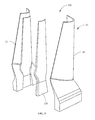
- FIG. 5 is an exploded view of the preformed CMC component including a ceramic foam core, prior to tooling.
- FIG. 6 shows a perspective view of an exemplary embodiment of tool used to make blade assemblies.
- FIG. 7 is a flow chart of the method of forming the component of the present disclosure.
- CMC components minimize or eliminate the limiting aspects of CMC material properties and manufacturing constraints and improve the mechanical loading capability.
- An embodiment of the disclosure is shown in FIGS. 2 and 3 , but the present disclosure is not limited to the illustrated structure.
- Power generation systems include, but are not limited to, gas turbines, steam turbines, and other turbine assemblies.
- FIG. 1 shows an example of a power generation system 10 , a gas turbine engine, having a compressor section 12 , a combustor section 14 and a turbine section 16 .
- turbine section 16 there are alternating rows of stationary airfoils 18 (commonly referred to as vanes) and rotating airfoils 20 (commonly referred to as blades).
- Each row of blades 20 is formed by a plurality of airfoils 20 attached to a disc 22 provided on a rotor 24 .
- Blades 20 can extend radially outward from discs 22 and terminate in a region known as a blade tip 26 .
- Each row of vanes 18 is formed by attaching plurality of vanes 18 to a vane carrier 28 .
- Vanes 18 can extend radially inward from the inner peripheral surface 30 of vane carrier 28 .
- Vane carrier 28 is attached to an outer casing 32 , which encloses turbine section 16 of engine 10 .
- high temperature and high velocity gases flow through rows of vanes 18 and blades 20 in turbine section 16 .
- FIG. 2 is a perspective view of a ceramic matrix composite (CMC) component 100 of power generation system 10 after tooling.
- component 100 is, but not limited to, gas turbine engine components, including combustor components, high pressure turbine vanes and blades, and other hot section components, such as but not limited to, airfoils, vanes, ceramic box shrouds and nozzle applications.
- the CMC component 100 is a blade 20 .
- Component 100 includes a ceramic foam core 120 and a ceramic matrix composite (CMC) material 130 surrounding at least a portion of ceramic foam core 120 .
- Ceramic foam core 120 remains in place during operation of CMC component 100 in power generation system 10 .
- Ceramic foam core 120 is formed from a material that withstands the CMC curing process and becomes a part of the final CMC component 100 .
- the material for the ceramic foam core 120 includes, but is not limited to, mullite, silica, zironica, zircon, and combinations thereof
- the ceramic foam core 120 is constructed from silicon carbide (SiC) or silicon boron (SiB) materials using a mold. The mold provides the desired geometry for ceramic foam core 120 .
- Ceramic foam core 120 is an open cell foam core or a closed cell foam core.
- CMC component 100 includes an oxide based CMC such as AN-720 (oxide-oxide based), which is available from COI Ceramics, Inc., San Diego, Calif., or a hybrid oxide CMC material such as the ones disclosed in U.S. Pat. No. 6,733,907, which is incorporated herein by reference in its entirety.
- oxide based CMC such as AN-720 (oxide-oxide based), which is available from COI Ceramics, Inc., San Diego, Calif., or a hybrid oxide CMC material such as the ones disclosed in U.S. Pat. No. 6,733,907, which is incorporated herein by reference in its entirety.
- component 100 is blade 20 having a leading edge 152 , a trailing edge 150 and a stem portion 156 .
- CMC material 130 of blade 20 surrounds at least a portion of ceramic foam core 120 .
- CMC material 130 completely surrounds ceramic foam core 120 .
- the sidewalls 160 of the CMC material 130 are adjacent to the ceramic foam core 120 and generally joined by ceramic foam core 120 (see FIG. 4 ).
- Ceramic foam core 120 provides additional stiffness or stability to CMC component 100 by forming unitary CMC component 100 . Additionally, ceramic foam core 120 provides improved vibration properties.
- ceramic form core 120 functions as a mandrel in fabricating CMC component 100 .
- Ceramic foam core 120 receives or is wrapped by the reinforcing fibers 132 .
- Reinforcing fibers 132 are arranged and disposed to form blade 20 .
- Reinforcing fibers 132 include uniaxial and or biaxial oriented material as well as general materials, such as, but not limited to quadraxial oriented materials, none crimp fabric (NCF), chopped strand mat, and knitted fabrics.
- CMC material 130 uses reinforcing fibers 132 impregnated with a matrix material 134 and further processed to form CMC material 130 .
- CMC material 130 is constructed from a pre-preg CMC material.
- pre-processed CMC material 130 of CMC component 100 includes a ceramic matrix 134 and at least one reinforcing layer 133 comprising a plurality of reinforcing fibers 132 (only a few fibers are shown in FIG. 4 to facilitate discussion) within the matrix 134 and an optional intermediate layer 138 applied to ceramic foam core 120 .
- the intermediate layer 138 is a laminate layer constructed from CMC plies.
- Reinforcing fibers 132 are selected from materials such as metallic fibers, ceramic fibers, carbon fibers, and combinations thereof
- CMC material 130 can optionally include intermediate layer 138 applied to ceramic foam core 120 prior to application of the plurality of reinforcing fibers 132 .
- CMC material 130 includes any suitable fiber architecture.
- Reinforcing fibers 132 of CMC 130 can be oriented to provide the desired strength properties.
- reinforcing fibers 132 can be oriented to provide anisotropic, orthotropic, or in-plane isotropic properties.
- reinforcing fibers 132 can be arranged at substantially 90 degrees relative to each other, such as a 0-90 degree orientation or a +/ ⁇ 45 degree orientation.
- Reinforcing fibers 132 can also be provided in multiple layers or laminate plies 136 .
- reinforcing fibers 132 are pre-impregnated before application.
- Ceramic matrix 134 is selected from materials such as SiC, SiN, SiB, and combinations thereof
- conventional ceramic matrix material processing is used to arrive at CMC component 100 .
- ceramic foam core 120 does not melt out of CMC component 100 . Even after the burn or rigidizing cycle, ceramic foam core 120 remains.
- high temperature CMC SiC foam is used for ceramic foam core 120 .
- the burn out cycle which is when preformed component 500 (see FIGS. 4-5 ) is placed in an oven at preset temperature to get rid of all the binders in CMC material 130 (volatile gasses) to form CMC component 100 , both CMC material 130 (or preformed parts 32 and 34 ) and ceramic foam core 120 undergo a transition that burns away all volatile substances, such as silicon.
- the resulting CMC component 100 has CMC material 130 and ceramic foam core 120 of comprising mainly carbon. Ceramic foam core 120 is situated between sidewalls 160 of CMC material 130 .
- the resulting CMC component 100 including both CMC material 130 and ceramic foam core 120 include a fragile porous carbon material having a toast-like texture or structure.
- CMC component 100 is formed using preformed CMC component 500 .
- Preformed CMC component 500 here a pre-processed blade 20 , is formed from pressure side part 32 and suction side part 34 surrounding ceramic foam core 120 .
- CMC material 130 that is used to create parts 32 and 34 is created using a laminate sequence of CMC plies in different combinations and thicknesses depending on the component to be produced.
- parts 32 and 34 include the necessary strength characteristics depending on the structure of the final component 100 .
- the parts 32 and 34 can include a final matrix ply on the outside of part.
- tool 200 can be used for fabricating CMC component 100 including the ceramic foam core 120 surrounded by pressure side preform 32 and suction side preform 34 .
- a pre-form blade 20 such as the one in FIG. 5 is situated or laid-up in tool 200 for rigidizing or densify the composite.
- tool 200 includes a first set of opposing sides 202 , 204 configured to abut each other and be fastened together.
- sides 202 , 204 can be arranged as a mold for component 100 or a section for holding the blade surrogate.
- Sides 202 , 204 can include a first layup surface 206 designed to permit fabrication of the desired shape for blade 10 .
- Tool 200 further includes a second set of opposing sides 208 , 210 configured to provide pressure on airfoil and dovetail, respectively (or, in the alternate embodiments, on the blade surrogate).
- Tool 200 may include a dovetail die 212 and/or a bridge 214 or other structures to provide a selectively configurable surface for laying up preform material, such as ceramic fiber material.
- the dovetail die 212 may further define a layup surface, for example the first layup surface.
- the dovetail die 212 is configured for the airfoil and dovetail preform and the integral platform preform to be co-rigidized.
- a Melt Infiltration (MI) process is used to complete the construction of CMC component 100 .
- a silicon boron material such as tetraboride (SiB 4 ), silicon hexaboride (SiB 6 ), or combinations thereof, is melted into CMC component 100 including ceramic foam core 120 and CMC material 120 using a wicking, gating, or other suitable process.
- the silicon boron material is absorbed by capillary absorption into all the carbon cavities that exist in CMC component 100 and ceramic foam core 120 .
- a method 700 of forming a ceramic matrix composite component 100 is shown in FIG. 7 .
- the method 700 includes providing a ceramic foam core 120 , step 702 (see FIG. 2 ).
- the ceramic foam core 120 has a predetermined geometry and operates as a mandrel for forming the component 100 .
- an intermediate layer 138 , or CMC laminate is applied to the ceramic foam core 120 , step 704 (see FIG. 4 ).
- the CMC pre-form 500 is assembled in a tool 200 (see FIG. 6 ) by surrounding the ceramic foam core 120 with pressure side preform 32 and suction side preform 34 , step 706 (see FIGS. 5-6 ).
- a plurality of reinforcing layers 133 are applied to the ceramic foam core 120 in tool 200 , step 706 (see FIGS. 4 and 6 ) to arrive at the desired preform component shape.
- the reinforcing layer 133 is impregnated with a matrix material 134 or the fibers are pre-impregnated before application.
- the preform component 500 , including ceramic foam core 120 is optionally autoclaved using tool 200 , step 708 .
- preform component 500 including ceramic foam core 120 are cured at a suitable temperature, such as, but not limited to, approximately 2700° F. to approximately 3400° F. or alternatively approximately 2750° F. to approximately 3300° F. or alternatively approximately 2800° F.
- step 710 Curing rigidizes the preform component 500 and ceramic foam core 120 and burns off excess organic materials and leaves a fragile porous carbon material having an almost toast-like texture or structure and having the general desired shape of the component 100 .
- the preform component and ceramic foam core 120 are densified by using melt infiltration or other suitable wicking techniques with silicon boron materials to form the CMC component 100 , step 712 (see FIG. 2 ).
- One advantage of an embodiment of the present disclosure includes a method that does not require the additional removal steps and cleaning steps associated with forming CMC components.
- Another advantage of an embodiment of the present disclosure includes a method that eliminates cleaning and re-melting of mandrels used in forming the CMC components.
- Another advantage of an embodiment of the present disclosure is that the component remains lightweight and hollow while permitting gas flow or pressurization of the internal cavity of the component.
- Yet another advantage of an embodiment of the present disclosure is that the component has unified sidewalls providing a complete unitary structural system thereby improving vibration and stiffness similar to a solid CMC blade with a weight reduction.
- Yet another advantage of an embodiment of the present disclosure is that it reduces laminate build time and ply assembly thereby driving down cost.
- Yet another advantage of an embodiment of the present disclosure is reduced CMC blade weight and lower centrifugal loads thereby allowing for a reduction in size and weight of rotors that receive the CMC blades.
- Another advantage includes reduced blade weight compared to a solid monolithic component.
- Another advantage of an embodiment of the present disclosure is that component has improved stiffness properties over a hollow CMC component.
Abstract
Description
Claims (20)
Priority Applications (3)
| Application Number | Priority Date | Filing Date | Title |
|---|---|---|---|
| US13/252,540 US8980435B2 (en) | 2011-10-04 | 2011-10-04 | CMC component, power generation system and method of forming a CMC component |
| CN201210368986.9A CN103030416B (en) | 2011-10-04 | 2012-09-27 | The method of CMC component, power generation system and formation CMC component |
| EP20120186824 EP2578553A3 (en) | 2011-10-04 | 2012-10-01 | A CMC component, power generation system and method of forming a CMC component |
Applications Claiming Priority (1)
| Application Number | Priority Date | Filing Date | Title |
|---|---|---|---|
| US13/252,540 US8980435B2 (en) | 2011-10-04 | 2011-10-04 | CMC component, power generation system and method of forming a CMC component |
Publications (2)
| Publication Number | Publication Date |
|---|---|
| US20130084189A1 US20130084189A1 (en) | 2013-04-04 |
| US8980435B2 true US8980435B2 (en) | 2015-03-17 |
Family
ID=47002699
Family Applications (1)
| Application Number | Title | Priority Date | Filing Date |
|---|---|---|---|
| US13/252,540 Active 2032-06-11 US8980435B2 (en) | 2011-10-04 | 2011-10-04 | CMC component, power generation system and method of forming a CMC component |
Country Status (3)
| Country | Link |
|---|---|
| US (1) | US8980435B2 (en) |
| EP (1) | EP2578553A3 (en) |
| CN (1) | CN103030416B (en) |
Cited By (12)
| Publication number | Priority date | Publication date | Assignee | Title |
|---|---|---|---|---|
| US20140311163A1 (en) * | 2011-12-30 | 2014-10-23 | Rolls-Royce North American Technologies, Inc. | Method of manufacturing a turbomachine component, an airfoil and a gas turbine engine |
| US20150040570A1 (en) * | 2013-03-03 | 2015-02-12 | Rolls-Royce North American Technologies, Inc. | Gas turbine engine component having foam core and composite skin with cooling slot |
| US20150147184A1 (en) * | 2013-11-25 | 2015-05-28 | General Electric Company | Process of producing a ceramic matrix composite turbine bucket, insert for a ceramic matrix composite turbine bucket and ceramic matrix composite turbine bucket |
| US20160047248A1 (en) * | 2014-08-15 | 2016-02-18 | Rolls-Royce Plc | Blade |
| US10723660B2 (en) | 2017-01-11 | 2020-07-28 | General Electric Company | Carbon yielding resin for melt infiltration |
| US11014857B2 (en) | 2017-09-20 | 2021-05-25 | General Electric Company | Contact interface for a composite component and methods of fabrication |
| US11149561B2 (en) | 2019-08-12 | 2021-10-19 | Rolls-Royce Plc | System and method for making ceramic matrix composite vane with profiled end walls |
| US20230101040A1 (en) * | 2020-03-17 | 2023-03-30 | Mitsubishi Heavy Industries, Ltd. | Composite-material blade, rotary machine, and method for forming composite-material blade |
| US11624287B2 (en) | 2020-02-21 | 2023-04-11 | Raytheon Technologies Corporation | Ceramic matrix composite component having low density core and method of making |
| US11697994B2 (en) * | 2020-02-07 | 2023-07-11 | Raytheon Technologies Corporation | CMC component with cooling protection |
| US11746660B2 (en) | 2021-12-20 | 2023-09-05 | Rolls-Royce Plc | Gas turbine engine components with foam filler for impact resistance |
| US11834956B2 (en) | 2021-12-20 | 2023-12-05 | Rolls-Royce Plc | Gas turbine engine components with metallic and ceramic foam for improved cooling |
Families Citing this family (25)
| Publication number | Priority date | Publication date | Assignee | Title |
|---|---|---|---|---|
| US9421733B2 (en) * | 2010-12-30 | 2016-08-23 | Rolls-Royce North American Technologies, Inc. | Multi-layer ceramic composite porous structure |
| US9663404B2 (en) * | 2012-01-03 | 2017-05-30 | General Electric Company | Method of forming a ceramic matrix composite and a ceramic matrix component |
| US9689265B2 (en) * | 2012-04-09 | 2017-06-27 | General Electric Company | Thin-walled reinforcement lattice structure for hollow CMC buckets |
| US10011043B2 (en) * | 2012-04-27 | 2018-07-03 | General Electric Company | Method of producing an internal cavity in a ceramic matrix composite |
| US10450235B2 (en) | 2012-04-27 | 2019-10-22 | General Electric Company | Method of producing an internal cavity in a ceramic matrix composite and mandrel therefor |
| US9751807B2 (en) * | 2012-08-16 | 2017-09-05 | General Electric Company | Consumable core for manufacture of composite articles and related method |
| US9523149B2 (en) * | 2013-03-14 | 2016-12-20 | Rolls-Royce Corporation | Rapid ceramic matrix composite production method |
| JP6360162B2 (en) | 2013-05-29 | 2018-07-18 | ゼネラル・エレクトリック・カンパニイ | Method for forming a ceramic matrix composite component having cooling features |
| FR3008968B1 (en) * | 2013-07-23 | 2016-12-09 | Herakles | PROCESS FOR MANUFACTURING COMPOSITE MATERIAL PARTS BY LOW TEMPERATURE FUSION IMPREGNATION |
| WO2015047485A2 (en) * | 2013-07-29 | 2015-04-02 | United Technologies Corporation | Gas turbine engine cmc airfoil assembly |
| WO2015073096A2 (en) * | 2013-09-13 | 2015-05-21 | United Technologies Corporation | Fan platform |
| EP2902588B1 (en) | 2014-01-31 | 2020-06-24 | Ansaldo Energia IP UK Limited | Composite turbine blade for high-temperature applications |
| CN105459515B (en) * | 2014-08-28 | 2017-09-29 | 比亚迪股份有限公司 | A kind of ceramic substrate and preparation method thereof and a kind of power model |
| KR101931616B1 (en) | 2014-08-28 | 2019-02-13 | 비와이디 컴퍼니 리미티드 | Ceramic substrate, manufacturing method thereof, and power module |
| US10563522B2 (en) * | 2014-09-22 | 2020-02-18 | Rolls-Royce North American Technologies Inc. | Composite airfoil for a gas turbine engine |
| BE1022481B1 (en) * | 2014-10-28 | 2016-05-02 | Techspace Aero S.A. | DAWN WITH AXIAL TURBOMACHINE COMPRESSOR LATTICE |
| US10465534B2 (en) | 2015-06-05 | 2019-11-05 | Rolls-Royce North American Technologies, Inc. | Machinable CMC insert |
| US10458653B2 (en) * | 2015-06-05 | 2019-10-29 | Rolls-Royce Corporation | Machinable CMC insert |
| US10472976B2 (en) * | 2015-06-05 | 2019-11-12 | Rolls-Royce Corporation | Machinable CMC insert |
| EP3153666A1 (en) * | 2015-10-06 | 2017-04-12 | MTU Aero Engines GmbH | Ceramic hybrid blade for turbomachines |
| US10533432B2 (en) * | 2017-02-01 | 2020-01-14 | General Electric Company | Preform CMC article, CMC article, and method for forming CMC article |
| US11066335B2 (en) | 2017-09-06 | 2021-07-20 | General Electric Company | Articles for creating hollow structures in ceramic matrix composites |
| EP3793963B1 (en) * | 2018-05-15 | 2023-08-30 | Safran | Process for manufacturing a cmc part |
| EP3683406B1 (en) * | 2019-01-18 | 2023-11-29 | Ansaldo Energia Switzerland AG | Abradable hybrid material, particularly for seal elements in gas turbines, and manufacturing method thereof |
| US20210262354A1 (en) * | 2020-02-21 | 2021-08-26 | United Technologies Corporation | Ceramic matrix composite component having low density core and method of making |
Citations (24)
| Publication number | Priority date | Publication date | Assignee | Title |
|---|---|---|---|---|
| US3930085A (en) * | 1975-02-13 | 1975-12-30 | Us Army | Preparation of thermal barriers |
| US4422229A (en) * | 1979-02-24 | 1983-12-27 | Rolls-Royce Limited | Method of making an airfoil member for a gas turbine engine |
| US5403153A (en) | 1993-10-29 | 1995-04-04 | The United States Of America As Represented By The Secretary Of The Air Force | Hollow composite turbine blade |
| US5643521A (en) | 1992-08-19 | 1997-07-01 | Dieter Wildfang Gmbh | Process for producing sanitary fittings |
| US5904972A (en) | 1995-06-07 | 1999-05-18 | Tpi Technology Inc. | Large composite core structures formed by vacuum assisted resin transfer molding |
| US5997077A (en) | 1997-08-23 | 1999-12-07 | Volkswagen Ag | Deformable structure for protection of vehicle occupants |
| US6274078B1 (en) | 1999-01-27 | 2001-08-14 | General Electric Company | Method of removing cores from ceramic matrix composite articles |
| US6280550B1 (en) | 1998-12-15 | 2001-08-28 | General Electric Company | Fabrication of composite articles having an infiltrated matrix |
| US6441341B1 (en) | 2000-06-16 | 2002-08-27 | General Electric Company | Method of forming cooling holes in a ceramic matrix composite turbine components |
| EP1262801A1 (en) | 2001-05-23 | 2002-12-04 | Astrium GmbH | Ultra-light and ultra-rigid fully ceramic reflector and method for producing the same |
| US6607358B2 (en) * | 2002-01-08 | 2003-08-19 | General Electric Company | Multi-component hybrid turbine blade |
| US6627019B2 (en) | 2000-12-18 | 2003-09-30 | David C. Jarmon | Process for making ceramic matrix composite parts with cooling channels |
| US20050118369A1 (en) | 2002-01-28 | 2005-06-02 | Intelligent Engineering (Bahamas) Limited | Structural sandwich plate members |
| US7094021B2 (en) | 2004-02-02 | 2006-08-22 | General Electric Company | Gas turbine flowpath structure |
| EP1749971A2 (en) | 2005-08-04 | 2007-02-07 | Rolls-Royce plc | Gas turbine blade |
| US7229254B2 (en) | 2002-01-18 | 2007-06-12 | Siemens Aktiengesellschaft | Turbine blade with a reduced mass |
| US7343960B1 (en) | 1998-11-20 | 2008-03-18 | Rolls-Royce Corporation | Method and apparatus for production of a cast component |
| US7438655B2 (en) | 2006-06-01 | 2008-10-21 | Warrior Sports, Inc. | Hockey stick blade having rib stiffening system |
| US7753654B2 (en) | 2006-01-21 | 2010-07-13 | Rolls-Royce Plc | Aerofoils for gas turbine engines |
| US7757808B1 (en) | 2009-02-04 | 2010-07-20 | Gm Global Technology Operations, Inc. | Noise reduction system |
| US7765790B2 (en) | 2008-03-25 | 2010-08-03 | Amicable Inventions Llc | Stationary mechanical engines and subsonic jet engines using supersonic gas turbines |
| US20110027098A1 (en) | 2008-12-31 | 2011-02-03 | General Electric Company | Ceramic matrix composite blade having integral platform structures and methods of fabrication |
| US7950234B2 (en) | 2006-10-13 | 2011-05-31 | Siemens Energy, Inc. | Ceramic matrix composite turbine engine components with unitary stiffening frame |
| US20110180032A1 (en) | 2010-01-20 | 2011-07-28 | Firestar Engineering, Llc | Insulated combustion chamber |
Family Cites Families (2)
| Publication number | Priority date | Publication date | Assignee | Title |
|---|---|---|---|---|
| US6733907B2 (en) | 1998-03-27 | 2004-05-11 | Siemens Westinghouse Power Corporation | Hybrid ceramic material composed of insulating and structural ceramic layers |
| US20090004425A1 (en) * | 2007-06-28 | 2009-01-01 | The Boeing Company | Ceramic Matrix Composite Structure having Fluted Core and Method for Making the Same |
-
2011
- 2011-10-04 US US13/252,540 patent/US8980435B2/en active Active
-
2012
- 2012-09-27 CN CN201210368986.9A patent/CN103030416B/en active Active
- 2012-10-01 EP EP20120186824 patent/EP2578553A3/en not_active Ceased
Patent Citations (24)
| Publication number | Priority date | Publication date | Assignee | Title |
|---|---|---|---|---|
| US3930085A (en) * | 1975-02-13 | 1975-12-30 | Us Army | Preparation of thermal barriers |
| US4422229A (en) * | 1979-02-24 | 1983-12-27 | Rolls-Royce Limited | Method of making an airfoil member for a gas turbine engine |
| US5643521A (en) | 1992-08-19 | 1997-07-01 | Dieter Wildfang Gmbh | Process for producing sanitary fittings |
| US5403153A (en) | 1993-10-29 | 1995-04-04 | The United States Of America As Represented By The Secretary Of The Air Force | Hollow composite turbine blade |
| US5904972A (en) | 1995-06-07 | 1999-05-18 | Tpi Technology Inc. | Large composite core structures formed by vacuum assisted resin transfer molding |
| US5997077A (en) | 1997-08-23 | 1999-12-07 | Volkswagen Ag | Deformable structure for protection of vehicle occupants |
| US7343960B1 (en) | 1998-11-20 | 2008-03-18 | Rolls-Royce Corporation | Method and apparatus for production of a cast component |
| US6280550B1 (en) | 1998-12-15 | 2001-08-28 | General Electric Company | Fabrication of composite articles having an infiltrated matrix |
| US6274078B1 (en) | 1999-01-27 | 2001-08-14 | General Electric Company | Method of removing cores from ceramic matrix composite articles |
| US6441341B1 (en) | 2000-06-16 | 2002-08-27 | General Electric Company | Method of forming cooling holes in a ceramic matrix composite turbine components |
| US6627019B2 (en) | 2000-12-18 | 2003-09-30 | David C. Jarmon | Process for making ceramic matrix composite parts with cooling channels |
| EP1262801A1 (en) | 2001-05-23 | 2002-12-04 | Astrium GmbH | Ultra-light and ultra-rigid fully ceramic reflector and method for producing the same |
| US6607358B2 (en) * | 2002-01-08 | 2003-08-19 | General Electric Company | Multi-component hybrid turbine blade |
| US7229254B2 (en) | 2002-01-18 | 2007-06-12 | Siemens Aktiengesellschaft | Turbine blade with a reduced mass |
| US20050118369A1 (en) | 2002-01-28 | 2005-06-02 | Intelligent Engineering (Bahamas) Limited | Structural sandwich plate members |
| US7094021B2 (en) | 2004-02-02 | 2006-08-22 | General Electric Company | Gas turbine flowpath structure |
| EP1749971A2 (en) | 2005-08-04 | 2007-02-07 | Rolls-Royce plc | Gas turbine blade |
| US7753654B2 (en) | 2006-01-21 | 2010-07-13 | Rolls-Royce Plc | Aerofoils for gas turbine engines |
| US7438655B2 (en) | 2006-06-01 | 2008-10-21 | Warrior Sports, Inc. | Hockey stick blade having rib stiffening system |
| US7950234B2 (en) | 2006-10-13 | 2011-05-31 | Siemens Energy, Inc. | Ceramic matrix composite turbine engine components with unitary stiffening frame |
| US7765790B2 (en) | 2008-03-25 | 2010-08-03 | Amicable Inventions Llc | Stationary mechanical engines and subsonic jet engines using supersonic gas turbines |
| US20110027098A1 (en) | 2008-12-31 | 2011-02-03 | General Electric Company | Ceramic matrix composite blade having integral platform structures and methods of fabrication |
| US7757808B1 (en) | 2009-02-04 | 2010-07-20 | Gm Global Technology Operations, Inc. | Noise reduction system |
| US20110180032A1 (en) | 2010-01-20 | 2011-07-28 | Firestar Engineering, Llc | Insulated combustion chamber |
Non-Patent Citations (2)
| Title |
|---|
| Search Report and Written Opinion from EP Application No. 12186824.4 dated Jan. 17, 2013. |
| Search Report from EP Application No. 12186824.4 dated Feb. 11, 2014. |
Cited By (15)
| Publication number | Priority date | Publication date | Assignee | Title |
|---|---|---|---|---|
| US9920634B2 (en) * | 2011-12-30 | 2018-03-20 | Rolls-Royce Corporation | Method of manufacturing a turbomachine component, an airfoil and a gas turbine engine |
| US20140311163A1 (en) * | 2011-12-30 | 2014-10-23 | Rolls-Royce North American Technologies, Inc. | Method of manufacturing a turbomachine component, an airfoil and a gas turbine engine |
| US20150040570A1 (en) * | 2013-03-03 | 2015-02-12 | Rolls-Royce North American Technologies, Inc. | Gas turbine engine component having foam core and composite skin with cooling slot |
| US9759090B2 (en) * | 2013-03-03 | 2017-09-12 | Rolls-Royce North American Technologies, Inc. | Gas turbine engine component having foam core and composite skin with cooling slot |
| US20150147184A1 (en) * | 2013-11-25 | 2015-05-28 | General Electric Company | Process of producing a ceramic matrix composite turbine bucket, insert for a ceramic matrix composite turbine bucket and ceramic matrix composite turbine bucket |
| US9896945B2 (en) * | 2013-11-25 | 2018-02-20 | General Electric Company | Process of producing a ceramic matrix composite turbine bucket, insert for a ceramic matrix composite turbine bucket and ceramic matrix composite turbine bucket |
| US20160047248A1 (en) * | 2014-08-15 | 2016-02-18 | Rolls-Royce Plc | Blade |
| US10723660B2 (en) | 2017-01-11 | 2020-07-28 | General Electric Company | Carbon yielding resin for melt infiltration |
| US11014857B2 (en) | 2017-09-20 | 2021-05-25 | General Electric Company | Contact interface for a composite component and methods of fabrication |
| US11149561B2 (en) | 2019-08-12 | 2021-10-19 | Rolls-Royce Plc | System and method for making ceramic matrix composite vane with profiled end walls |
| US11697994B2 (en) * | 2020-02-07 | 2023-07-11 | Raytheon Technologies Corporation | CMC component with cooling protection |
| US11624287B2 (en) | 2020-02-21 | 2023-04-11 | Raytheon Technologies Corporation | Ceramic matrix composite component having low density core and method of making |
| US20230101040A1 (en) * | 2020-03-17 | 2023-03-30 | Mitsubishi Heavy Industries, Ltd. | Composite-material blade, rotary machine, and method for forming composite-material blade |
| US11746660B2 (en) | 2021-12-20 | 2023-09-05 | Rolls-Royce Plc | Gas turbine engine components with foam filler for impact resistance |
| US11834956B2 (en) | 2021-12-20 | 2023-12-05 | Rolls-Royce Plc | Gas turbine engine components with metallic and ceramic foam for improved cooling |
Also Published As
| Publication number | Publication date |
|---|---|
| EP2578553A2 (en) | 2013-04-10 |
| CN103030416A (en) | 2013-04-10 |
| CN103030416B (en) | 2016-06-22 |
| EP2578553A3 (en) | 2014-03-12 |
| US20130084189A1 (en) | 2013-04-04 |
Similar Documents
| Publication | Publication Date | Title |
|---|---|---|
| US8980435B2 (en) | CMC component, power generation system and method of forming a CMC component | |
| EP3153484B1 (en) | Ceramic matrix composite component and process of producing a ceramic matrix composite component | |
| EP2617695B1 (en) | Method of forming a ceramic matrix composite and a ceramic matrix composite component | |
| EP2828052B1 (en) | Process for producing ceramic composite components | |
| EP2893150B1 (en) | Airfoil components containing ceramic-based materials and processes therefor | |
| JP5537564B2 (en) | Ceramic matrix composite blade having an integral platform and method of manufacturing the same | |
| US9981438B2 (en) | Pre-form ceramic matrix composite cavity and a ceramic matrix composite component | |
| JP7034583B2 (en) | Process for manufacturing ceramic matrix composite parts and ceramic matrix composite parts |
Legal Events
| Date | Code | Title | Description |
|---|---|---|---|
| AS | Assignment |
Owner name: GENERAL ELECTRIC COMPANY, NEW YORK Free format text: ASSIGNMENT OF ASSIGNORS INTEREST;ASSIGNOR:DE DIEGO, PETER;REEL/FRAME:027012/0850 Effective date: 20111004 |
|
| FEPP | Fee payment procedure |
Free format text: PAYOR NUMBER ASSIGNED (ORIGINAL EVENT CODE: ASPN); ENTITY STATUS OF PATENT OWNER: LARGE ENTITY |
|
| STCF | Information on status: patent grant |
Free format text: PATENTED CASE |
|
| MAFP | Maintenance fee payment |
Free format text: PAYMENT OF MAINTENANCE FEE, 4TH YEAR, LARGE ENTITY (ORIGINAL EVENT CODE: M1551); ENTITY STATUS OF PATENT OWNER: LARGE ENTITY Year of fee payment: 4 |
|
| MAFP | Maintenance fee payment |
Free format text: PAYMENT OF MAINTENANCE FEE, 8TH YEAR, LARGE ENTITY (ORIGINAL EVENT CODE: M1552); ENTITY STATUS OF PATENT OWNER: LARGE ENTITY Year of fee payment: 8 |
|
| AS | Assignment |
Owner name: GE INFRASTRUCTURE TECHNOLOGY LLC, SOUTH CAROLINA Free format text: ASSIGNMENT OF ASSIGNORS INTEREST;ASSIGNOR:GENERAL ELECTRIC COMPANY;REEL/FRAME:065727/0001 Effective date: 20231110 |