US8972891B2 - Method for handling objects representing annotations on an interactive input system and interactive input system executing the method - Google Patents
Method for handling objects representing annotations on an interactive input system and interactive input system executing the method Download PDFInfo
- Publication number
- US8972891B2 US8972891B2 US13/076,638 US201113076638A US8972891B2 US 8972891 B2 US8972891 B2 US 8972891B2 US 201113076638 A US201113076638 A US 201113076638A US 8972891 B2 US8972891 B2 US 8972891B2
- Authority
- US
- United States
- Prior art keywords
- annotation
- new
- input stream
- identifier
- interactive surface
- Prior art date
- Legal status (The legal status is an assumption and is not a legal conclusion. Google has not performed a legal analysis and makes no representation as to the accuracy of the status listed.)
- Active, expires
Links
Images


Classifications
-
- G—PHYSICS
- G06—COMPUTING; CALCULATING OR COUNTING
- G06F—ELECTRIC DIGITAL DATA PROCESSING
- G06F3/00—Input arrangements for transferring data to be processed into a form capable of being handled by the computer; Output arrangements for transferring data from processing unit to output unit, e.g. interface arrangements
- G06F3/01—Input arrangements or combined input and output arrangements for interaction between user and computer
- G06F3/048—Interaction techniques based on graphical user interfaces [GUI]
-
- G—PHYSICS
- G06—COMPUTING; CALCULATING OR COUNTING
- G06F—ELECTRIC DIGITAL DATA PROCESSING
- G06F3/00—Input arrangements for transferring data to be processed into a form capable of being handled by the computer; Output arrangements for transferring data from processing unit to output unit, e.g. interface arrangements
- G06F3/01—Input arrangements or combined input and output arrangements for interaction between user and computer
- G06F3/03—Arrangements for converting the position or the displacement of a member into a coded form
- G06F3/041—Digitisers, e.g. for touch screens or touch pads, characterised by the transducing means
- G06F3/042—Digitisers, e.g. for touch screens or touch pads, characterised by the transducing means by opto-electronic means
- G06F3/0425—Digitisers, e.g. for touch screens or touch pads, characterised by the transducing means by opto-electronic means using a single imaging device like a video camera for tracking the absolute position of a single or a plurality of objects with respect to an imaged reference surface, e.g. video camera imaging a display or a projection screen, a table or a wall surface, on which a computer generated image is displayed or projected
-
- G—PHYSICS
- G06—COMPUTING; CALCULATING OR COUNTING
- G06F—ELECTRIC DIGITAL DATA PROCESSING
- G06F3/00—Input arrangements for transferring data to be processed into a form capable of being handled by the computer; Output arrangements for transferring data from processing unit to output unit, e.g. interface arrangements
- G06F3/01—Input arrangements or combined input and output arrangements for interaction between user and computer
- G06F3/03—Arrangements for converting the position or the displacement of a member into a coded form
- G06F3/041—Digitisers, e.g. for touch screens or touch pads, characterised by the transducing means
- G06F3/042—Digitisers, e.g. for touch screens or touch pads, characterised by the transducing means by opto-electronic means
-
- G—PHYSICS
- G06—COMPUTING; CALCULATING OR COUNTING
- G06F—ELECTRIC DIGITAL DATA PROCESSING
- G06F3/00—Input arrangements for transferring data to be processed into a form capable of being handled by the computer; Output arrangements for transferring data from processing unit to output unit, e.g. interface arrangements
- G06F3/01—Input arrangements or combined input and output arrangements for interaction between user and computer
- G06F3/048—Interaction techniques based on graphical user interfaces [GUI]
- G06F3/0481—Interaction techniques based on graphical user interfaces [GUI] based on specific properties of the displayed interaction object or a metaphor-based environment, e.g. interaction with desktop elements like windows or icons, or assisted by a cursor's changing behaviour or appearance
- G06F3/04812—Interaction techniques based on cursor appearance or behaviour, e.g. being affected by the presence of displayed objects
-
- G—PHYSICS
- G06—COMPUTING; CALCULATING OR COUNTING
- G06F—ELECTRIC DIGITAL DATA PROCESSING
- G06F3/00—Input arrangements for transferring data to be processed into a form capable of being handled by the computer; Output arrangements for transferring data from processing unit to output unit, e.g. interface arrangements
- G06F3/01—Input arrangements or combined input and output arrangements for interaction between user and computer
- G06F3/048—Interaction techniques based on graphical user interfaces [GUI]
- G06F3/0487—Interaction techniques based on graphical user interfaces [GUI] using specific features provided by the input device, e.g. functions controlled by the rotation of a mouse with dual sensing arrangements, or of the nature of the input device, e.g. tap gestures based on pressure sensed by a digitiser
- G06F3/0488—Interaction techniques based on graphical user interfaces [GUI] using specific features provided by the input device, e.g. functions controlled by the rotation of a mouse with dual sensing arrangements, or of the nature of the input device, e.g. tap gestures based on pressure sensed by a digitiser using a touch-screen or digitiser, e.g. input of commands through traced gestures
- G06F3/04883—Interaction techniques based on graphical user interfaces [GUI] using specific features provided by the input device, e.g. functions controlled by the rotation of a mouse with dual sensing arrangements, or of the nature of the input device, e.g. tap gestures based on pressure sensed by a digitiser using a touch-screen or digitiser, e.g. input of commands through traced gestures for inputting data by handwriting, e.g. gesture or text
-
- G—PHYSICS
- G06—COMPUTING; CALCULATING OR COUNTING
- G06F—ELECTRIC DIGITAL DATA PROCESSING
- G06F3/00—Input arrangements for transferring data to be processed into a form capable of being handled by the computer; Output arrangements for transferring data from processing unit to output unit, e.g. interface arrangements
- G06F3/14—Digital output to display device ; Cooperation and interconnection of the display device with other functional units
-
- G—PHYSICS
- G06—COMPUTING; CALCULATING OR COUNTING
- G06F—ELECTRIC DIGITAL DATA PROCESSING
- G06F40/00—Handling natural language data
- G06F40/10—Text processing
- G06F40/166—Editing, e.g. inserting or deleting
- G06F40/169—Annotation, e.g. comment data or footnotes
-
- G06K9/00422—
-
- G06K9/00442—
-
- G—PHYSICS
- G06—COMPUTING; CALCULATING OR COUNTING
- G06V—IMAGE OR VIDEO RECOGNITION OR UNDERSTANDING
- G06V30/00—Character recognition; Recognising digital ink; Document-oriented image-based pattern recognition
- G06V30/10—Character recognition
- G06V30/32—Digital ink
- G06V30/36—Matching; Classification
-
- G—PHYSICS
- G06—COMPUTING; CALCULATING OR COUNTING
- G06V—IMAGE OR VIDEO RECOGNITION OR UNDERSTANDING
- G06V30/00—Character recognition; Recognising digital ink; Document-oriented image-based pattern recognition
- G06V30/40—Document-oriented image-based pattern recognition
-
- G—PHYSICS
- G06—COMPUTING; CALCULATING OR COUNTING
- G06F—ELECTRIC DIGITAL DATA PROCESSING
- G06F2203/00—Indexing scheme relating to G06F3/00 - G06F3/048
- G06F2203/041—Indexing scheme relating to G06F3/041 - G06F3/045
- G06F2203/04109—FTIR in optical digitiser, i.e. touch detection by frustrating the total internal reflection within an optical waveguide due to changes of optical properties or deformation at the touch location
Definitions
- the present invention relates generally to interactive input systems and in particular, to a method for handling objects representing annotations on an interactive input system and an interactive input system executing the method.
- Interactive input systems that allow users to inject input (e.g. digital ink, mouse events etc.) into an application program using an active pointer (e.g. a pointer that emits light, sound or other signal), a passive pointer (e.g. a finger, cylinder or other suitable object) or other suitable input device such as for example, a mouse or trackball, are known.
- active pointer e.g. a pointer that emits light, sound or other signal
- a passive pointer e.g. a finger, cylinder or other suitable object
- suitable input device such as for example, a mouse or trackball
- Multi-touch interactive input systems that receive and process input from multiple pointers using machine vision are also known.
- One such type of multi-touch interactive input system exploits the well-known optical phenomenon of frustrated total internal reflection (FTIR).
- FTIR frustrated total internal reflection
- the machine vision system captures images including the point(s) of escaped light, and processes the images to identify the position of the pointers on the waveguide surface based on the point(s) of escaped light for use as input to application programs.
- the application programs are often configured to receive the processed touch point data, and to interpret the touch point data as Contact Down, Contact Move, or Contact Up events.
- an annotation object is created for each Contact Down-Contact Up cycle. For example, an annotation object representing a freeform letter ‘L’ would be created upon completion of a Contact Down event at a particular position, a series of Contact Move events together traversing the shape of the ‘L’, and a Contact Up event at the end. It will be understood that the application programs and annotation objects themselves do not have to be aware that what is drawn in freeform actually represents any particular letter, shape, number etc.
- annotations it can be useful for an application program to automatically group separate annotation objects into a particular whole.
- a user is freeform printing letters of a word, with each letter being represented by a respective annotation object, it is often useful to for the user to be able to easily select the entire word so that it can be manipulated as a word rather than only as discrete letters.
- selection methods are known in which a user can enter a “Selection” mode and manually select various keyboard-typed characters or graphic objects such as icons by manually sweep a pointer across a plurality of graphic objects in order to temporarily group them using a selection box, methods for successfully automating grouping of annotations in particularly useful ways are underdeveloped.
- U.S. Pat. No. 6,320,597 to leperen discloses a method for editing objects representing writing on an electronic writeboard.
- an object representing writing is created on the electronic writeboard, and it is determined if the created object overlies an existing object by at least a threshold amount.
- the created and existing objects are automatically merged to create a new object if the created object overlies the existing object by at least a threshold amount. While the patent teaches a very useful method and system, it does not contemplate time lapsed between creation of a writing object. As such, created and existing objects may be merged regardless as to how long after the existing object the created object was created. Furthermore, this patent does not contemplate editing of objects in a multi-user interactive input system.
- U.S. Pat. No. 5,889,523 to Wilcox et al. discloses a method and apparatus for dynamically grouping a plurality of graphic objects for graphical editing.
- Graphic objects in a graphical editing system are grouped using hierarchical agglomerative clustering to form a cluster tree.
- the cluster tree is based on different types of distances, such as time distance and spatial distance, where the different types of distances are combined into a single distance metric.
- the system permits a user, via a user interface control element, to traverse the cluster tree thereby to cluster a selected graphic object with others dynamically in various ways according to the user's needs.
- U.S. Pat. No. 5,784,061 to Moran et al. discloses a method and apparatus for representing a group of graphic objects so as to maximize usage of a display area on a computer controlled graphics display system.
- a means is provided for “collapsing” a group of graphic objects so that the group is represented by a container icon.
- a user performs a gesture using an input device on the system at a position close to the graphic objects intended to be grouped.
- U.S. Pat. No. 5,471,578 to Moran et al. discloses a graphical editing system which allows a user to manually modify a selection gesture without having to redraw the entire gesture.
- the system defines a selection with an enclosure that is treated as a graphical object that can be manually contorted in a style consistent with the specific application.
- a method of handling objects representing annotations on an interactive input system comprising:
- a further annotation is created on the interactive input system within the threshold distance of the temporary grouping region.
- An identifier of an input stream used to create the annotation with an identifier of the input stream used to created the further annotation are compared.
- the further annotation is associated with the temporary grouping region and the further annotation is added to an annotation group.
- the further annotation is associated with a further temporary grouping region.
- an interactive input system comprising:
- processing structure communicating with the display surface, the processing structure displaying an annotation on the display surface, associating the annotation with a temporary grouping region and, in the event that a threshold amount of time passes before a further annotation is created within a threshold distance of the temporary grouping region, disabling the temporary grouping region to thereafter prevent automatic grouping with the annotation of any further annotation.
- a computer readable medium embodying a computer program for handling objects representing annotations on an interactive input system, the computer program comprising:
- the method and system disclosed herein enable delimiting of grouping of annotations based on distance of a further annotation from the temporary grouping region, and also based on whether a further annotation is made within a threshold amount of time.
- the flexibility of automatic grouping based on proximity and time is provided without the complexity and processing intensity normally associated with prior art systems that attempt to maintain a high number of grouping options, rather than actual groups.
- Embodiments comparing identifiers of input streams used to create annotations are capable of providing significant advantages in multiple user scenarios where automatic grouping of each user's respective annotations is desired.
- FIG. 1 is a perspective view of an interactive input system
- FIG. 2A is a side sectional view of the interactive input system of FIG. 1 ;
- FIG. 2B is a sectional view of a table top and touch panel forming part of the interactive input system of FIG. 1 ;
- FIG. 2C is a sectional view of the touch panel of 2 B, having been contacted by a pointer;
- FIG. 2D illustrates an alternative embodiment of the interactive input system
- FIG. 2E shows a software structure of an interactive input system
- FIG. 2F shows a top level flowchart of a method of ink annotation auto-grouping implemented in the interactive input system.
- FIG. 3 is a flowchart showing a method for handling annotation objects
- FIG. 4 is a class diagram showing relationships between objects in an automatic annotation grouping system
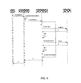
- FIG. 5 is a sequence diagram showing function calls and events subsequent to a Contact Down event that initiates the creation of an annotation object
- FIG. 6 is a flowchart showing steps taken subsequent to a Contact Down event
- FIG. 7 is a sequence diagram showing function calls and events for dispatching a created annotation object
- FIG. 8 is a flowchart showing steps taken during dispatching of the created annotation object.
- FIGS. 9A to 9G illustrate a scenario in which annotations are being created on an interactive input system by two different users concurrently.
- the following provides a method for handling objects representing annotations on an interactive input system, and an interactive input system executing the method. While the following describes the method executed in one particular type of interactive input system, it will be understood that the method may be used in various types of interactive input systems. For example, the method is quite suitable for execution in interactive input systems such as those described above, that are capable of receiving an input stream and creating annotations such as ink or freeform drawings in response thereto.
- FIG. 1 a perspective diagram of an interactive input system in the form of a touch table is shown and is generally identified by reference numeral 10 .
- Touch table 10 comprises a table top 12 mounted atop a cabinet 16 .
- cabinet 16 sits atop wheels, castors or the like 18 that enable the touch table 10 to be easily moved from place to place as requested.
- a coordinate input device in the form of a frustrated total internal reflection (FTIR) based touch panel 14 that enables detection and tracking of one or more pointers 11 , such as fingers, pens, hands, cylinders, or other objects, applied thereto.
- FTIR frustrated total internal reflection
- Cabinet 16 supports the table top 12 and touch panel 14 , and houses processing structure 20 (see FIG. 2A ) executing a host application and one or more application programs.
- Image data generated by the processing structure 20 is displayed on the touch panel 14 allowing a user to interact with the displayed image via pointer contacts on the display surface 15 of the touch panel 14 .
- the processing structure 20 interprets pointer contacts as input to the running application program and updates the image data accordingly so that the image displayed on the display surface 15 reflects the pointer activity. In this manner, the touch panel 14 and processing structure 20 allow pointer interactions with the touch panel 14 to be recorded as handwriting or drawing or used to control execution of the application program.
- Processing structure 20 in this embodiment is a general purpose computing device in the form of a computer.
- the computer comprises for example, a processing unit, system memory (volatile and/or non-volatile memory), other non-removable or removable memory (a hard disk drive, RAM, ROM, EEPROM, CD-ROM, DVD, flash memory etc.) and a system bus coupling the various computer components to the processing unit.
- system memory volatile and/or non-volatile memory
- other non-removable or removable memory a hard disk drive, RAM, ROM, EEPROM, CD-ROM, DVD, flash memory etc.
- system bus coupling the various computer components to the processing unit.
- a graphical user interface comprising a canvas page or palette (i.e. a background), upon which graphic widgets are displayed, is displayed on the display surface of the touch panel 14 .
- the graphical user interface enables freeform or handwritten ink objects (“annotations”) and other objects to be input and manipulated via pointer interaction with the display surface 15 of the touch panel 14 .
- the cabinet 16 also houses a horizontally-oriented projector 22 , an infrared (IR) filter 24 , and mirrors 26 , 28 and 30 .
- An imaging device 32 in the form of an infrared-detecting camera is mounted on a bracket 33 adjacent mirror 28 .
- the system of mirrors 26 , 28 and 30 functions to “fold” the images projected by projector 22 within cabinet 16 along the light path without unduly sacrificing image size.
- the overall touch table 10 dimensions can thereby be made compact.
- the imaging device 32 is aimed at mirror 30 and thus sees a reflection of the display surface 15 in order to mitigate the appearance of hotspot noise in captured images that typically must be dealt with in systems having imaging devices that are directed at the display surface itself.
- Imaging device 32 is positioned within the cabinet 16 by the bracket 33 so that it does not interfere with the light path of the projected image.
- processing structure 20 outputs video data to projector 22 which, in turn, projects images through the IR filter 24 onto the first mirror 26 .
- the projected images now with IR light having been substantially filtered out, are reflected by the first mirror 26 onto the second mirror 28 .
- Second mirror 28 in turn reflects the images to the third mirror 30 .
- the third mirror 30 reflects the projected video images onto the display (bottom) surface of the touch panel 14 .
- the video images projected on the bottom surface of the touch panel 14 are viewable through the touch panel 14 from above.
- the system of three mirrors 26 , 28 configured as shown provides a compact path along which the projected image can be channeled to the display surface.
- Projector 22 is oriented horizontally in order to preserve projector bulb life, as commonly-available projectors are typically designed for horizontal placement.
- An external data port/switch in this embodiment a Universal Serial Bus (USB) port/switch 34 , extends from the interior of the cabinet 16 through the cabinet wall to the exterior of the touch table 10 providing access for insertion and removal of a USB key 36 , as well as switching of functions.
- USB Universal Serial Bus
- the USB port/switch 34 , projector 22 , and imaging device 32 are each connected to and managed by the processing structure 20 .
- a power supply (not shown) supplies electrical power to the electrical components of the touch table 10 .
- the power supply may be an external unit or, for example, a universal power supply within the cabinet 16 for improving portability of the touch table 10 .
- the cabinet 16 fully encloses its contents in order to restrict the levels of ambient visible and infrared light entering the cabinet 16 thereby to facilitate satisfactory signal to noise performance. Doing this can compete with various techniques for managing heat within the cabinet 16 .
- the touch panel 14 , the projector 22 , and the processing structure are all sources of heat, and such heat if contained within the cabinet 16 for extended periods of time can reduce the life of components, affect performance of components, and create heat waves that can distort the optical components of the touch table 10 .
- the cabinet 16 houses heat managing provisions (not shown) to introduce cooler ambient air into the cabinet while exhausting hot air from the cabinet.
- the heat management provisions may be of the type disclosed in U.S. patent application Ser. No. 12/240,953 to Sirotich et al., filed on Sep.
- FIG. 2B is a sectional view of the table top 12 and touch panel 14 .
- Table top 12 comprises a frame 120 formed of plastic supporting the touch panel 14 .
- Touch panel 14 comprises an optical waveguide 144 that, according to this embodiment, is a sheet of acrylic.
- a resilient diffusion layer 146 in this embodiment a layer of V-CARE® V-LITE® barrier fabric manufactured by Vintex Inc. of Mount Forest, Ontario, Canada, or other suitable material lies against the optical waveguide 144 .
- the diffusion layer 146 when pressed into contact with the optical waveguide 144 , substantially reflects the IR light escaping the optical waveguide 144 so that the escaping 1 R light travels down into the cabinet 16 .
- the diffusion layer 146 also diffuses visible light being projected onto it in order to display the projected image.
- the protective layer 148 is a thin sheet of polycarbonate material over which is applied a hardcoat of Marnoto material, manufactured by Tekra Corporation of New Berlin, Wisconsin, U.S.A. While the touch panel 14 may function without the protective layer 148 , the protective layer 148 permits use of the touch panel 14 without undue discoloration, snagging or creasing of the underlying diffusion layer 146 , and without undue wear on users' fingers. Furthermore, the protective layer 148 provides abrasion, scratch and chemical resistance to the overall touch panel 14 , as is useful for panel longevity.
- the protective layer 148 , diffusion layer 146 , and optical waveguide 144 are clamped together at their edges as a unit and mounted within the table top 12 . Over time, prolonged use may wear one or more of the layers. As desired, the edges of the layers may be unclamped in order to inexpensively provide replacements for the worn layers. It will be understood that the layers may be kept together in other ways, such as by use of one or more of adhesives, friction fit, screws, nails, or other fastening methods.
- An IR light source comprising a bank of infrared light emitting diodes (LEDs) 142 is positioned along at least one side surface of the optical waveguide 144 (into the page in FIG. 2 b ). Each LED 142 emits infrared light into the optical waveguide 144 .
- the side surface along which the IR LEDs 142 are positioned is flame-polished to facilitate reception of light from the IR LEDs 142 .
- An air gap of 1-2 millimeters (mm) is maintained between the IR LEDs 142 and the side surface of the optical waveguide 144 in order to reduce heat transmittance from the IR LEDs 142 to the optical waveguide 144 , and thereby mitigate heat distortions in the acrylic optical waveguide 144 .
- Bonded to the other side surfaces of the optical waveguide 144 is reflective tape 143 to reflect light back into the optical waveguide 144 thereby saturating the optical waveguide 144 with infrared illumination.
- IR light is introduced via the flame-polished side surface of the optical waveguide 144 in a direction generally parallel to its large upper and lower surfaces.
- the IR light does not escape through the upper or lower surfaces of the optical waveguide 144 due to total internal reflection (TIR) because its angle of incidence at the upper and lower surfaces is not sufficient to allow for its escape.
- TIR total internal reflection
- the IR light reaching other side surfaces is generally reflected entirely back into the optical waveguide 144 by the reflective tape 143 at the other side surfaces.
- the escaping IR light reflects off of the point 11 and scatters locally downward through the optical waveguide 144 and exits the optical waveguide 144 through its bottom surface. This occurs for each pointer 11 as it contacts the display surface of the touch panel 114 at a respective touch point.
- the imaging device 32 captures two-dimensional, IR video images of the third mirror 30 .
- IR light having been filtered from the images projected by projector 22 , in combination with the cabinet 16 substantially keeping out ambient light, ensures that the background of the images captured by imaging device 32 is substantially black.
- the images captured by IR camera 32 comprise one or more bright points corresponding to respective touch points.
- the processing structure 20 receives the captured images and performs image processing to detect the coordinates and characteristics of the one or more bright points in the captured image that represent touch points. The touch point coordinates are then mapped to display coordinates.
- a host application tracks each touch point, and handles continuity processing between image frames. More particularly, the host application receives touch point data from frames and based on the touch point data determines whether to register a new touch point, modify an existing touch point, or cancel/delete an existing touch point. Thus, the host application registers a Contact Down event representing a new touch point when it receives touch point data that is not related to an existing touch point, and accords the new touch point a unique identifier. Touch point data may be considered unrelated to an existing touch point if it characterizes a touch point that is a threshold distance away from an existing touch point, for example.
- the host application registers a Contact Move event representing movement of the touch point when it receives touch point data that is related to an existing pointer, for example by being within a threshold distance of, or overlapping an existing touch point, but having a different focal point.
- the host application registers a Contact Up event representing removal of the touch point from the surface of the touch panel 14 when touch point data that can be associated with an existing touch point ceases to be received from subsequent images.
- the Contact Down, Contact Move and Contact Up events are passed to respective elements of the user interface such as graphical objects, widgets, or the background/canvas, based on the element with which the touch point is currently associated, and/or the touch point's current position. These events are then interpreted as mouse or ink events by application programs running on the processing structure 20 .
- FIG. 2 d illustrates an alternative embodiment of the interactive input system 200 .
- an interactive whiteboard (IWB) 202 is connected to a host computer 204 , allowing multiple pointers (stylus, finger, mouse, etc.) to write on the interactive surface of the IWB 202 .
- the host computer 204 is connected to a network 208 (Local Area Network, Internet, etc.) to receive inputs from remote computers 210 and 212 that are connected to the network via wireless or wired means, respectively, to allow the users of the remote computers to input to the interactive input surface of the IWB 202 .
- network 208 Local Area Network, Internet, etc.
- application programs configured to enable each user to produce freeform ink writing or drawing on a background or canvas create an annotation object for ink between the Contact Down and Contact Up events.
- annotations it can be useful to automatically group separate annotation objects into a particular whole. For example, where a user is freeform printing letters of a word, with each letter being represented by a respective annotation object, it is often useful for a user to be able to easily select the entire word so that the entire word can be manipulated through editing, scaling, translating, and so forth.
- FIG. 2E shows the software structure of the interactive input system.
- Application 242 communicates with the operating system (OS) 244 of the host computer 204 to receive input streams, and interprets the input streams as ink annotations.
- the input streams are provided to the OS 244 by the driver (e.g., the mouse driver and/or IWB driver) 246 , and, if remote computers are connected to the host computer 204 , by the remote pointer events 248 originating from the remote computers.
- the driver e.g., the mouse driver and/or IWB driver
- the application 242 adapts to a variety of system configurations and a variety of IWB hardware.
- the application 242 identifies input of ink annotations from various input streams and automatically groups ink annotations generated from each input device (e.g., a stylus, a finger, a mouse, or an ink annotation originating on a remote device) according to a set of rules.
- FIG. 2F shows the top level flowchart of the method of automatically grouping ink annotations, that is implemented in the interactive input system.
- the host computer 204 receives inputs, it first the separate inputs into different input streams according to differentiable identities (e.g., device type and ID) of the input device or source (step 260 ). For example, inputs with a mouse ID will be treated as a mouse input stream associated with the identified mouse ID.
- identity e.g., device type and ID
- An input stream is identified with an input stream identifier that is allocated at the board or firmware level. For example, a locally connected mouse will cause Contact Down/Move/Up events that are associated with an input stream identifier that is different from the input stream identifier associated with Contact Down/Move/Up events caused by a pointer contacting a touch surface of the interactive input system. Furthermore, the interactive input system tracks whether a tool has changed for a given input stream (such as from a red pen pointer to a blue pen pointer) and will affect grouping as will be described.
- each mouse will thereby generate a unique input stream.
- stylus inputs with an ID will be identified as a stylus input stream associated with the ID.
- each stylus ID will correspond to a separate input stream.
- the IWB driver detects multiple simultaneous stylus inputs but cannot differentiate them, the multiple inputs will be as one input stream.
- the system examines each input stream to further split an input stream into multiple streams, if possible.
- the touch inputs which are identified as one input stream at step 260 , are examined at step 262 . If the location on the interactive surface at which a touch input P 1 occurred at time t 1 is within a threshold distance from the location at which another touch input P 2 occurred at time t 2 , and the difference in time between t 1 and t 2 is within a threshold amount, the touch inputs P 1 and P 2 are recorded as part of the same input stream. However, if P 1 is located outside of a threshold distance from P 2 then P 1 and P 2 are recorded as two distinct input streams.
- the separation of input streams is also subject to other criteria, as will be described in more detail below.
- step 264 the system checks each input stream obtained from step 262 and automatically groups annotations in each input stream according to a number of rules.
- an annotation object created from an input stream is automatically grouped with a previously-created annotation object under certain conditions.
- the annotation object and the previously-created annotation object were created from input streams having the same input stream identifier, they are automatically grouped together if the annotation object was created at a location that is within a threshold distance from the previously-created annotation object, and also was created before expiry of a threshold amount of time from the time of creation of the previously-created annotation object.
- an annotation object that, for example, is intended to represent a letter in a word, is automatically grouped with an existing annotation object that is located within a threshold distance of the annotation object and that itself was created no more than a threshold amount of time prior to creation of the annotation object.
- the annotation object is automatically grouped with a further annotation object, if the further annotation object is created at a location that is within a threshold distance of the annotation object and is itself created no more than a threshold amount of time after creation of the (just previously created) annotation object.
- the threshold amount of time is 2 seconds
- the threshold distance is 20 pixels.
- the threshold amount of time can be up to 3 seconds, and/or the threshold distance can be up to 200 pixels.
- Other thresholds may be defined within these ranges or outside of them, depending on the implementation requirements for the application.
- a mechanism for preventing further annotations from being automatically grouped with one or more existing annotations.
- a method of handling annotation objects 300 that includes creating an annotation (step 310 ), associating the annotation with a temporary grouping region (step 320 ) and, in the event that the temporary grouping region expires (step 330 ), disabling the temporary grouping region to thereafter prevent automatic grouping with the annotation of any further annotation (step 340 ).
- the temporary grouping region expires in the event that a threshold amount of time passes before a further annotation is created within a threshold distance of the temporary grouping region. In general, this means that two annotations that are created at sufficiently separate times will not be grouped together, despite their perhaps being created physically close to each other.
- FIG. 4 there is shown a class diagram of relationships between classes from which objects are derived in an automatic annotation grouping system, according to this embodiment.
- An AutoGroupCoordinator class is derived from the IAutoGroupCoordinator interface, which exposes two main methods as available upon occurrence of contact events. These two main methods are the OnContactDown method and the OnObjectDispatch method.
- the AutoGroupCoordinator object contains a collection of AutoGroupState objects. AutoGroupState objects are grouped into lists of objects, represented by objects of the AutoGroupStateList class, according to the input stream used to create the objects. More particularly, an AutoGroupStateList object is created for each input stream being used with the interactive input system.
- an input stream from a mouse that is locally connected to the interactive input system is associated with an AutoGroupStateList object
- an input stream from a pointer being used to interact with a touch surface of the interactive input stream is associated with a different AutoGroupStateList object.
- different types of pointers used to interact with such a touch surface may represent different input streams and may therefore be associated with respective AutoGroupStateList objects.
- the AutoGroupStateList and AutoGroupState classes are derived respectively from interface classes IAutoGroupStateList and IAutoGroupState.
- the AutoGroupReferences class is a data structure representing user preferences, and is shared between multiple AutoGroupState objects.
- the AutoGroupReferences class is instantiated once per AutoGroupCoordinator lifetime, and encapsulates Get( )methods exposed through IAutoGroupReferences for reading preferences stored in the AutoGroupReferences object.
- An AutoGroupState object represents a temporary grouping region, and permits several persistent states that are used for the automatic grouping of annotations.
- the IAutoGroupState interface exposes a CanGroup( ) method, which receives a newly created annotation object exposed through an IDisplayObject interface as a parameter.
- the CanGroup( ) method returns an enumerator that specifies how the newly created annotation object can be dispatched.
- the CanGroup( ) method may specify that the newly created annotation object can be dispatched to the group associated with the AutoGroupState object, can be dispatched to a newly created group for association with the AutoGroupState object along with the previously-created annotation object, or can be dispatched without being associated with a group.
- the automatic annotation grouping system prepares for the potential of grouping of the annotation object being created, as shown in FIGS. 5 and 6 .
- the AutoGroupStateList object associated with the input stream being used to create the annotation object is consulted by the AutoGroupCoordinator object for a list of AutoGroupState objects associated with that input stream. If the AutoGroupStateList object for the input stream being used to create the object does not yet exist, the AutoGroupStateList object is created, and an AutoGroupState object is created and added to the AutoGroupStateList.
- each AutoGroupState object in the list is checked to determine whether there has been a tool change since the previous Contact Up event for that input stream. This is done by invoking an IsToolChanged method and receiving the result.
- Each AutoGroupState object in the list is also checked to determine whether the threshold amount of time has passed since the last Contact Up event for that input stream, by invoking an IsGroupTimeExpired method and receiving the result.
- the AutoGroupState object being tested may be disabled (i.e. reset) to thereafter prevent further annotations from being grouped with the annotations in the group associated with the AutoGroupState object. This process is iterated through all of the AutoGroupState objects in the AutoGroupStateList for the input stream.
- an AutoGroupState object is disabled as indicated above by removing it from the AutoGroupStateList and destroying it.
- the last AutoGroupState object in the AutoGroupStateList is not removed from the AutoGroupStateList or destroyed but is disabled by resetting it to clear all of its references and resetting its expiry time. The reason the last AutoGroupState object in the AutoGroupStateList is not removed or destroyed is simply so that it can be re-used thereby to improve performance by avoiding having to re-create another AutoGroupState object.
- a dispatching routine begins in order to dispatch the new annotation object created using the pen tool, as shown in FIGS. 7 and 8 .
- dispatching an annotation object refers to the association of the annotation object with a page on the display surface of the interactive input system, and the potential grouping of the annotation object with one or more other annotation objects.
- the pen tool object invokes a DoObjectDispatch method in order to cause the AutoGroupCoordinator object to retrieve from the AutoGroupStateList object a list of enabled AutoGroupState objects associated with that input stream.
- the CanGroup( ) method of each enabled AutoGroupState object associated with the input stream is passed the newly created annotation object in order to determine whether the newly created annotation object may be dispatched to a group associated with the AutoGroupState object (DispatchAndGroup). Alternatively, it may be grouped with the last dispatched annotation object associated with the input stream by creating an annotation group and dispatching both the newly created annotation object and the last dispatched annotation object to the annotation group (DispatchAndGroup). Alternatively, it is determined that the newly created annotation object is not to be grouped.
- a newly created annotation object may be dispatched to the group or otherwise grouped with the previously dispatched annotation object if it is within a threshold distance of the temporary grouping region represented by the AutoGroupState object. More particularly, the newly created annotation object is grouped if it is within a threshold distance of the previously dispatched annotation object or a group of annotation objects created using the same input stream where the temporary grouping region has not expired. A newly created annotation group is designated as the “current” group in the AutoGroupState object for the next Contact Down/Up cycle.
- the newly dispatched annotation object is designated as the last-dispatched annotation object for a next Contact Down/Up cycle.
- FIGS. 9 a to 9 f illustrate a scenario in which annotations are being created by two different users concurrently.
- a first user is creating a “W” annotation with a pen tool, as indicated by the dashed line.
- FIG. 9 b the first user has lifted his pen and a second user is creating an “H” annotation with a different pen tool, as indicated by the solid line.
- FIG. 9 c the first user is creating a second annotation, this time an “e”, and the second user has lifted his pen to begin creating his second annotation.
- FIG. 9 d the first user has lifted his pen as the second user is creating his second annotation, this time an “e’.
- annotation objects created from the same input stream may, in some circumstances, be grouped together.
- determination of separate respective groupings for multiple users' annotations may occur simply because one user creates an annotation at a location that is greater than a the threshold distance away from an annotation created by another user, as shown in FIGS. 8 a to 8 g.
- Grouping of multiple users' annotations may be useful, in certain applications.
- grouping of annotation objects created using multiple different input streams is preferably a configurable option, and/or is dependent upon the particular application in connection with which annotations are being made.
- a spelling game could be devised that, as students proceeded through game levels, reduced the time thresholds accordingly so as to increase the challenge at higher levels.
- an interactive input system may not be capable of providing input stream identifiers unique to each input stream for distinguishing between certain input streams.
- the interactive input system treats input streams that do not have distinguishable input stream identifiers provided by the system hardware, firmware or application program simply as a single input stream.
- the methods described above may be embodied in one or more software applications comprising computer executable instructions executed by the processing structure 20 .
- the software application(s) may comprise program modules including routines, programs, object components, data structures etc. and may be embodied as computer readable program code stored on a computer readable medium.
- the computer readable medium is any data storage device that can store data, which can thereafter be read by a processing structure 20 . Examples of computer readable media include for example read-only memory, random-access memory, CD-ROMs, magnetic tape and optical data storage devices.
- the computer readable program code can also be distributed over a network including coupled computer systems so that the computer readable program code is stored and executed in a distributed fashion.
- the methods described above may be applied to any interactive input system that can enable one or more users to provide ink inputs.
- the methods and systems described herein are not limited for use with any particular input devices.
- the interactive input system described above is in the form of a multi-touch table supporting multiple users, because the methods described herein handle annotations created using one or more input streams, they are not limited for use with only a mouse, or a pen, or a finger.
- an input stream may be generated via input devices through a remote desktop connection, by an application program automatically, as hardware level service events, or by any other means of creating an input stream.
Abstract
Description
Claims (12)
Priority Applications (2)
| Application Number | Priority Date | Filing Date | Title |
|---|---|---|---|
| US13/076,638 US8972891B2 (en) | 2010-04-26 | 2011-03-31 | Method for handling objects representing annotations on an interactive input system and interactive input system executing the method |
| US14/606,538 US20150143222A1 (en) | 2010-04-26 | 2015-01-27 | Method for handling objects representing annotations on an interactive input system and interactive input system executing the method |
Applications Claiming Priority (2)
| Application Number | Priority Date | Filing Date | Title |
|---|---|---|---|
| US32798510P | 2010-04-26 | 2010-04-26 | |
| US13/076,638 US8972891B2 (en) | 2010-04-26 | 2011-03-31 | Method for handling objects representing annotations on an interactive input system and interactive input system executing the method |
Related Child Applications (1)
| Application Number | Title | Priority Date | Filing Date |
|---|---|---|---|
| US14/606,538 Continuation US20150143222A1 (en) | 2010-04-26 | 2015-01-27 | Method for handling objects representing annotations on an interactive input system and interactive input system executing the method |
Publications (2)
| Publication Number | Publication Date |
|---|---|
| US20110265034A1 US20110265034A1 (en) | 2011-10-27 |
| US8972891B2 true US8972891B2 (en) | 2015-03-03 |
Family
ID=44816854
Family Applications (2)
| Application Number | Title | Priority Date | Filing Date |
|---|---|---|---|
| US13/076,638 Active 2032-08-24 US8972891B2 (en) | 2010-04-26 | 2011-03-31 | Method for handling objects representing annotations on an interactive input system and interactive input system executing the method |
| US14/606,538 Abandoned US20150143222A1 (en) | 2010-04-26 | 2015-01-27 | Method for handling objects representing annotations on an interactive input system and interactive input system executing the method |
Family Applications After (1)
| Application Number | Title | Priority Date | Filing Date |
|---|---|---|---|
| US14/606,538 Abandoned US20150143222A1 (en) | 2010-04-26 | 2015-01-27 | Method for handling objects representing annotations on an interactive input system and interactive input system executing the method |
Country Status (4)
| Country | Link |
|---|---|
| US (2) | US8972891B2 (en) |
| EP (1) | EP2564298A4 (en) |
| KR (1) | KR20130073902A (en) |
| WO (1) | WO2011134046A1 (en) |
Cited By (1)
| Publication number | Priority date | Publication date | Assignee | Title |
|---|---|---|---|---|
| US20150143222A1 (en) * | 2010-04-26 | 2015-05-21 | SMART Techologies ULC | Method for handling objects representing annotations on an interactive input system and interactive input system executing the method |
Families Citing this family (11)
| Publication number | Priority date | Publication date | Assignee | Title |
|---|---|---|---|---|
| JP2013026878A (en) * | 2011-07-22 | 2013-02-04 | Sony Corp | Information processing apparatus, information processing method, and program |
| KR101984823B1 (en) | 2012-04-26 | 2019-05-31 | 삼성전자주식회사 | Method and Device for annotating a web page |
| JP5681838B2 (en) | 2012-05-31 | 2015-03-11 | マルチタッチ オーユーMultitouch Oy | User interface for drawing with electronic devices |
| US9443098B2 (en) | 2012-12-19 | 2016-09-13 | Pandexio, Inc. | Multi-layered metadata management system |
| JP5862610B2 (en) * | 2013-06-17 | 2016-02-16 | コニカミノルタ株式会社 | Image display device, display control program, and display control method |
| US9773000B2 (en) | 2013-10-29 | 2017-09-26 | Pandexio, Inc. | Knowledge object and collaboration management system |
| US10270819B2 (en) | 2014-05-14 | 2019-04-23 | Microsoft Technology Licensing, Llc | System and method providing collaborative interaction |
| US9552473B2 (en) * | 2014-05-14 | 2017-01-24 | Microsoft Technology Licensing, Llc | Claiming data from a virtual whiteboard |
| US11513678B2 (en) * | 2017-06-06 | 2022-11-29 | Polycom, Inc. | Context based annotating in an electronic presentation system |
| US10867124B2 (en) * | 2018-03-26 | 2020-12-15 | Apple Inc. | Manual annotations using clustering, anchoring, and transformation |
| US10353997B1 (en) * | 2018-04-09 | 2019-07-16 | Amazon Technologies, Inc. | Freeform annotation transcription |
Citations (24)
| Publication number | Priority date | Publication date | Assignee | Title |
|---|---|---|---|---|
| US5404439A (en) | 1992-04-15 | 1995-04-04 | Xerox Corporation | Time-space object containment for graphical user interface |
| US5448263A (en) | 1991-10-21 | 1995-09-05 | Smart Technologies Inc. | Interactive display system |
| US5471578A (en) | 1993-12-30 | 1995-11-28 | Xerox Corporation | Apparatus and method for altering enclosure selections in a gesture based input system |
| US5784061A (en) | 1996-06-26 | 1998-07-21 | Xerox Corporation | Method and apparatus for collapsing and expanding selected regions on a work space of a computer controlled display system |
| US5899523A (en) | 1997-12-06 | 1999-05-04 | Richards; Larry L. | Rain-deflecting trim molding for use on camping type recreational vehicles |
| US6054990A (en) | 1996-07-05 | 2000-04-25 | Tran; Bao Q. | Computer system with handwriting annotation |
| US6141000A (en) | 1991-10-21 | 2000-10-31 | Smart Technologies Inc. | Projection display system with touch sensing on screen, computer assisted alignment correction and network conferencing |
| US6279014B1 (en) * | 1997-09-15 | 2001-08-21 | Xerox Corporation | Method and system for organizing documents based upon annotations in context |
| US6320597B1 (en) | 1998-04-06 | 2001-11-20 | Smart Technologies, Inc. | Method for editing objects representing writing on an electronic writeboard |
| WO2002098049A2 (en) | 2001-05-31 | 2002-12-05 | Empower Technologies, Inc. | System and method of pen-based data input into a computing device |
| US6803906B1 (en) | 2000-07-05 | 2004-10-12 | Smart Technologies, Inc. | Passive touch system and method of detecting user input |
| US20070120762A1 (en) * | 2005-11-30 | 2007-05-31 | O'gorman Robert W | Providing information in a multi-screen device |
| US7232986B2 (en) | 2004-02-17 | 2007-06-19 | Smart Technologies Inc. | Apparatus for detecting a pointer within a region of interest |
| US7274356B2 (en) | 2003-10-09 | 2007-09-25 | Smart Technologies Inc. | Apparatus for determining the location of a pointer within a region of interest |
| US20090109231A1 (en) * | 2007-10-26 | 2009-04-30 | Sung Nam Kim | Imaging Device Providing Soft Buttons and Method of Changing Attributes of the Soft Buttons |
| US7532196B2 (en) * | 2003-10-30 | 2009-05-12 | Microsoft Corporation | Distributed sensing techniques for mobile devices |
| AU2007286532B2 (en) | 2006-09-06 | 2009-08-06 | Apple Inc. | Touch screen device, method, and graphical user interface for determining commands by applying heuristics |
| US20100070878A1 (en) * | 2008-09-12 | 2010-03-18 | At&T Intellectual Property I, L.P. | Providing sketch annotations with multimedia programs |
| US20100079409A1 (en) | 2008-09-29 | 2010-04-01 | Smart Technologies Ulc | Touch panel for an interactive input system, and interactive input system incorporating the touch panel |
| US20100153835A1 (en) * | 2008-12-17 | 2010-06-17 | Business Objects, S.A. | Linking annotations to document objects |
| US20110022470A1 (en) * | 2009-07-21 | 2011-01-27 | Sridhar Varadarajan | System and Method for Real-Time Ad Selection and Scheduling |
| US20110022941A1 (en) * | 2006-04-11 | 2011-01-27 | Brian Osborne | Information Extraction Methods and Apparatus Including a Computer-User Interface |
| US20110040644A1 (en) * | 2009-08-12 | 2011-02-17 | Google, Inc. | Annotating content |
| US20120221243A1 (en) * | 2008-09-19 | 2012-08-30 | International Business Machines Corporation | Sharing gps navigation information |
Family Cites Families (3)
| Publication number | Priority date | Publication date | Assignee | Title |
|---|---|---|---|---|
| US7158675B2 (en) * | 2002-05-14 | 2007-01-02 | Microsoft Corporation | Interfacing with ink |
| US8751921B2 (en) * | 2008-07-24 | 2014-06-10 | Microsoft Corporation | Presenting annotations in hierarchical manner |
| EP2564298A4 (en) * | 2010-04-26 | 2015-05-27 | Smart Technologies Ulc | Method for handling objects representing annotations on an interactive input system and interactive input system executing the method |
-
2011
- 2011-03-31 EP EP11774215.5A patent/EP2564298A4/en not_active Ceased
- 2011-03-31 KR KR1020127030856A patent/KR20130073902A/en not_active Application Discontinuation
- 2011-03-31 US US13/076,638 patent/US8972891B2/en active Active
- 2011-03-31 WO PCT/CA2011/000330 patent/WO2011134046A1/en active Application Filing
-
2015
- 2015-01-27 US US14/606,538 patent/US20150143222A1/en not_active Abandoned
Patent Citations (27)
| Publication number | Priority date | Publication date | Assignee | Title |
|---|---|---|---|---|
| US6747636B2 (en) | 1991-10-21 | 2004-06-08 | Smart Technologies, Inc. | Projection display and system with pressure sensing at screen, and computer assisted alignment implemented by applying pressure at displayed calibration marks |
| US5448263A (en) | 1991-10-21 | 1995-09-05 | Smart Technologies Inc. | Interactive display system |
| US6141000A (en) | 1991-10-21 | 2000-10-31 | Smart Technologies Inc. | Projection display system with touch sensing on screen, computer assisted alignment correction and network conferencing |
| US6337681B1 (en) | 1991-10-21 | 2002-01-08 | Smart Technologies Inc. | Projection display system with pressure sensing at screen, and computer assisted alignment implemented by applying pressure at displayed calibration marks |
| US5404439A (en) | 1992-04-15 | 1995-04-04 | Xerox Corporation | Time-space object containment for graphical user interface |
| US5471578A (en) | 1993-12-30 | 1995-11-28 | Xerox Corporation | Apparatus and method for altering enclosure selections in a gesture based input system |
| US5784061A (en) | 1996-06-26 | 1998-07-21 | Xerox Corporation | Method and apparatus for collapsing and expanding selected regions on a work space of a computer controlled display system |
| US6054990A (en) | 1996-07-05 | 2000-04-25 | Tran; Bao Q. | Computer system with handwriting annotation |
| US6279014B1 (en) * | 1997-09-15 | 2001-08-21 | Xerox Corporation | Method and system for organizing documents based upon annotations in context |
| US5899523A (en) | 1997-12-06 | 1999-05-04 | Richards; Larry L. | Rain-deflecting trim molding for use on camping type recreational vehicles |
| US6320597B1 (en) | 1998-04-06 | 2001-11-20 | Smart Technologies, Inc. | Method for editing objects representing writing on an electronic writeboard |
| US6803906B1 (en) | 2000-07-05 | 2004-10-12 | Smart Technologies, Inc. | Passive touch system and method of detecting user input |
| US7236162B2 (en) | 2000-07-05 | 2007-06-26 | Smart Technologies, Inc. | Passive touch system and method of detecting user input |
| WO2002098049A2 (en) | 2001-05-31 | 2002-12-05 | Empower Technologies, Inc. | System and method of pen-based data input into a computing device |
| US7274356B2 (en) | 2003-10-09 | 2007-09-25 | Smart Technologies Inc. | Apparatus for determining the location of a pointer within a region of interest |
| US7532196B2 (en) * | 2003-10-30 | 2009-05-12 | Microsoft Corporation | Distributed sensing techniques for mobile devices |
| US7232986B2 (en) | 2004-02-17 | 2007-06-19 | Smart Technologies Inc. | Apparatus for detecting a pointer within a region of interest |
| US20070120762A1 (en) * | 2005-11-30 | 2007-05-31 | O'gorman Robert W | Providing information in a multi-screen device |
| US20110022941A1 (en) * | 2006-04-11 | 2011-01-27 | Brian Osborne | Information Extraction Methods and Apparatus Including a Computer-User Interface |
| AU2007286532B2 (en) | 2006-09-06 | 2009-08-06 | Apple Inc. | Touch screen device, method, and graphical user interface for determining commands by applying heuristics |
| US20090109231A1 (en) * | 2007-10-26 | 2009-04-30 | Sung Nam Kim | Imaging Device Providing Soft Buttons and Method of Changing Attributes of the Soft Buttons |
| US20100070878A1 (en) * | 2008-09-12 | 2010-03-18 | At&T Intellectual Property I, L.P. | Providing sketch annotations with multimedia programs |
| US20120221243A1 (en) * | 2008-09-19 | 2012-08-30 | International Business Machines Corporation | Sharing gps navigation information |
| US20100079409A1 (en) | 2008-09-29 | 2010-04-01 | Smart Technologies Ulc | Touch panel for an interactive input system, and interactive input system incorporating the touch panel |
| US20100153835A1 (en) * | 2008-12-17 | 2010-06-17 | Business Objects, S.A. | Linking annotations to document objects |
| US20110022470A1 (en) * | 2009-07-21 | 2011-01-27 | Sridhar Varadarajan | System and Method for Real-Time Ad Selection and Scheduling |
| US20110040644A1 (en) * | 2009-08-12 | 2011-02-17 | Google, Inc. | Annotating content |
Non-Patent Citations (1)
| Title |
|---|
| Transmittal; International Search Report; and Written Opinion of the International Searching Authority for International Application No. PCT/CA2011/000330, with a mailing date of Jun. 27, 2011. |
Cited By (1)
| Publication number | Priority date | Publication date | Assignee | Title |
|---|---|---|---|---|
| US20150143222A1 (en) * | 2010-04-26 | 2015-05-21 | SMART Techologies ULC | Method for handling objects representing annotations on an interactive input system and interactive input system executing the method |
Also Published As
| Publication number | Publication date |
|---|---|
| EP2564298A1 (en) | 2013-03-06 |
| US20150143222A1 (en) | 2015-05-21 |
| WO2011134046A1 (en) | 2011-11-03 |
| EP2564298A4 (en) | 2015-05-27 |
| KR20130073902A (en) | 2013-07-03 |
| US20110265034A1 (en) | 2011-10-27 |
Similar Documents
| Publication | Publication Date | Title |
|---|---|---|
| US8972891B2 (en) | Method for handling objects representing annotations on an interactive input system and interactive input system executing the method | |
| US9262016B2 (en) | Gesture recognition method and interactive input system employing same | |
| CA2738185C (en) | Touch-input with crossing-based widget manipulation | |
| CA2741956C (en) | Handling interactions in multi-user interactive input system | |
| US20180032168A1 (en) | Multi-touch uses, gestures, and implementation | |
| US20100079409A1 (en) | Touch panel for an interactive input system, and interactive input system incorporating the touch panel | |
| US20160342779A1 (en) | System and method for universal user interface configurations | |
| US9261987B2 (en) | Method of supporting multiple selections and interactive input system employing same | |
| US20090231281A1 (en) | Multi-touch virtual keyboard | |
| US20100302144A1 (en) | Creating a virtual mouse input device | |
| US9035882B2 (en) | Computer input device | |
| US20120176308A1 (en) | Method for supporting multiple menus and interactive input system employing same | |
| KR20120040970A (en) | Method and apparatus for recognizing gesture in the display | |
| US9092085B2 (en) | Configuring a touchpad setting based on the metadata of an active application of an electronic device | |
| US20150277717A1 (en) | Interactive input system and method for grouping graphical objects | |
| US20050275635A1 (en) | Manipulating association of data with a physical object | |
| CN203422725U (en) | Touch screen multiple-point display system | |
| EP2663914A1 (en) | Method of supporting multiple selections and interactive input system employing same |
Legal Events
| Date | Code | Title | Description |
|---|---|---|---|
| AS | Assignment |
Owner name: SMART TECHNOLOGIES ULC, CANADA Free format text: ASSIGNMENT OF ASSIGNORS INTEREST;ASSIGNORS:GARIN, ALEXANDER;PHAM, ANN DANG;ROUNDING, KATHRYN;AND OTHERS;SIGNING DATES FROM 20110520 TO 20110525;REEL/FRAME:026420/0229 |
|
| AS | Assignment |
Owner name: MORGAN STANLEY SENIOR FUNDING INC., NEW YORK Free format text: SECURITY AGREEMENT;ASSIGNORS:SMART TECHNOLOGIES ULC;SMART TECHNOLOGIES INC.;REEL/FRAME:030935/0848 Effective date: 20130731 Owner name: MORGAN STANLEY SENIOR FUNDING, INC., NEW YORK Free format text: SECURITY AGREEMENT;ASSIGNORS:SMART TECHNOLOGIES ULC;SMART TECHNOLOGIES INC.;REEL/FRAME:030935/0879 Effective date: 20130731 |
|
| STCF | Information on status: patent grant |
Free format text: PATENTED CASE |
|
| AS | Assignment |
Owner name: SMART TECHNOLOGIES INC., CANADA Free format text: RELEASE OF TERM LOAN SECURITY INTEREST;ASSIGNOR:MORGAN STANLEY SENIOR FUNDING, INC.;REEL/FRAME:040713/0123 Effective date: 20161003 Owner name: SMART TECHNOLOGIES INC., CANADA Free format text: RELEASE OF ABL SECURITY INTEREST;ASSIGNOR:MORGAN STANLEY SENIOR FUNDING, INC.;REEL/FRAME:040711/0956 Effective date: 20161003 Owner name: SMART TECHNOLOGIES ULC, CANADA Free format text: RELEASE OF ABL SECURITY INTEREST;ASSIGNOR:MORGAN STANLEY SENIOR FUNDING, INC.;REEL/FRAME:040711/0956 Effective date: 20161003 Owner name: SMART TECHNOLOGIES ULC, CANADA Free format text: RELEASE OF TERM LOAN SECURITY INTEREST;ASSIGNOR:MORGAN STANLEY SENIOR FUNDING, INC.;REEL/FRAME:040713/0123 Effective date: 20161003 |
|
| AS | Assignment |
Owner name: SMART TECHNOLOGIES ULC, CANADA Free format text: RELEASE BY SECURED PARTY;ASSIGNOR:MORGAN STANLEY SENIOR FUNDING, INC.;REEL/FRAME:040798/0077 Effective date: 20161003 Owner name: SMART TECHNOLOGIES INC., CANADA Free format text: RELEASE BY SECURED PARTY;ASSIGNOR:MORGAN STANLEY SENIOR FUNDING, INC.;REEL/FRAME:040798/0077 Effective date: 20161003 Owner name: SMART TECHNOLOGIES ULC, CANADA Free format text: RELEASE BY SECURED PARTY;ASSIGNOR:MORGAN STANLEY SENIOR FUNDING, INC.;REEL/FRAME:040819/0306 Effective date: 20161003 Owner name: SMART TECHNOLOGIES INC., CANADA Free format text: RELEASE BY SECURED PARTY;ASSIGNOR:MORGAN STANLEY SENIOR FUNDING, INC.;REEL/FRAME:040819/0306 Effective date: 20161003 |
|
| MAFP | Maintenance fee payment |
Free format text: PAYMENT OF MAINTENANCE FEE, 4TH YEAR, LARGE ENTITY (ORIGINAL EVENT CODE: M1551); ENTITY STATUS OF PATENT OWNER: LARGE ENTITY Year of fee payment: 4 |
|
| MAFP | Maintenance fee payment |
Free format text: PAYMENT OF MAINTENANCE FEE, 8TH YEAR, LARGE ENTITY (ORIGINAL EVENT CODE: M1552); ENTITY STATUS OF PATENT OWNER: LARGE ENTITY Year of fee payment: 8 |