US8964129B2 - Light engine and rear projection television - Google Patents
Light engine and rear projection television Download PDFInfo
- Publication number
- US8964129B2 US8964129B2 US13/927,393 US201313927393A US8964129B2 US 8964129 B2 US8964129 B2 US 8964129B2 US 201313927393 A US201313927393 A US 201313927393A US 8964129 B2 US8964129 B2 US 8964129B2
- Authority
- US
- United States
- Prior art keywords
- plate
- light
- collimating lens
- prism
- leds
- Prior art date
- Legal status (The legal status is an assumption and is not a legal conclusion. Google has not performed a legal analysis and makes no representation as to the accuracy of the status listed.)
- Expired - Fee Related
Links
Images


Classifications
-
- G—PHYSICS
- G03—PHOTOGRAPHY; CINEMATOGRAPHY; ANALOGOUS TECHNIQUES USING WAVES OTHER THAN OPTICAL WAVES; ELECTROGRAPHY; HOLOGRAPHY
- G03B—APPARATUS OR ARRANGEMENTS FOR TAKING PHOTOGRAPHS OR FOR PROJECTING OR VIEWING THEM; APPARATUS OR ARRANGEMENTS EMPLOYING ANALOGOUS TECHNIQUES USING WAVES OTHER THAN OPTICAL WAVES; ACCESSORIES THEREFOR
- G03B21/00—Projectors or projection-type viewers; Accessories therefor
- G03B21/14—Details
- G03B21/20—Lamp housings
- G03B21/2006—Lamp housings characterised by the light source
- G03B21/2033—LED or laser light sources
-
- H—ELECTRICITY
- H04—ELECTRIC COMMUNICATION TECHNIQUE
- H04N—PICTORIAL COMMUNICATION, e.g. TELEVISION
- H04N9/00—Details of colour television systems
- H04N9/12—Picture reproducers
- H04N9/31—Projection devices for colour picture display, e.g. using electronic spatial light modulators [ESLM]
-
- F—MECHANICAL ENGINEERING; LIGHTING; HEATING; WEAPONS; BLASTING
- F21—LIGHTING
- F21V—FUNCTIONAL FEATURES OR DETAILS OF LIGHTING DEVICES OR SYSTEMS THEREOF; STRUCTURAL COMBINATIONS OF LIGHTING DEVICES WITH OTHER ARTICLES, NOT OTHERWISE PROVIDED FOR
- F21V13/00—Producing particular characteristics or distribution of the light emitted by means of a combination of elements specified in two or more of main groups F21V1/00 - F21V11/00
- F21V13/02—Combinations of only two kinds of elements
- F21V13/04—Combinations of only two kinds of elements the elements being reflectors and refractors
-
- G—PHYSICS
- G03—PHOTOGRAPHY; CINEMATOGRAPHY; ANALOGOUS TECHNIQUES USING WAVES OTHER THAN OPTICAL WAVES; ELECTROGRAPHY; HOLOGRAPHY
- G03B—APPARATUS OR ARRANGEMENTS FOR TAKING PHOTOGRAPHS OR FOR PROJECTING OR VIEWING THEM; APPARATUS OR ARRANGEMENTS EMPLOYING ANALOGOUS TECHNIQUES USING WAVES OTHER THAN OPTICAL WAVES; ACCESSORIES THEREFOR
- G03B21/00—Projectors or projection-type viewers; Accessories therefor
- G03B21/14—Details
- G03B21/28—Reflectors in projection beam
-
- G—PHYSICS
- G03—PHOTOGRAPHY; CINEMATOGRAPHY; ANALOGOUS TECHNIQUES USING WAVES OTHER THAN OPTICAL WAVES; ELECTROGRAPHY; HOLOGRAPHY
- G03B—APPARATUS OR ARRANGEMENTS FOR TAKING PHOTOGRAPHS OR FOR PROJECTING OR VIEWING THEM; APPARATUS OR ARRANGEMENTS EMPLOYING ANALOGOUS TECHNIQUES USING WAVES OTHER THAN OPTICAL WAVES; ACCESSORIES THEREFOR
- G03B33/00—Colour photography, other than mere exposure or projection of a colour film
Definitions
- the present disclosure relates to rear projection televisions and, particularly, to a light engine for a rear projection television and the rear projection television using the light engine.
- Rear projection televisions generally include a light engine, a reflecting mirror, and a display. Light rays emitting from the light engine project onto the reflecting mirror. The reflecting mirror reflects the light rays to the display.
- the light engine includes a telecentric lens to decrease distortion of images. However, the telecentric lens generally needs a longer projection distance to project the light rays, which necessarily increases the size of the light engine and the rear projection televisions.
- FIG. 1 is a schematic view of a rear projection television in accordance with an exemplary embodiment.
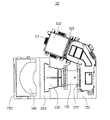
- FIG. 2 is an isometric view of a light engine of the rear projection television of FIG. 1 .
- FIG. 3 is a schematic view of the light engine of FIG. 2 .
- FIGS. 1-3 show a rear projection television 100 according to an exemplary embodiment.
- the rear projection television 100 includes a light engine 10 , a reflecting mirror 20 , and a display 30 .
- the light engine 10 emits light rays to the reflecting mirror 20 , and includes a light source module 11 , an optical assembly 12 , a collimating lens 13 , a reflecting lens 14 , and a supporting plate 15 .
- the light source module 11 includes three light emitting diodes (LEDs) 111 and an X-prism 112 .
- the X-prism 112 is a cuboid and includes four side surfaces 1121 .
- the three LEDs 111 are attached on three of the four side surfaces 1121 .
- the three LEDs 111 respectively emit red, green, and blue lights.
- the red, green, and blue lights emitted from the LEDs 111 are combined by the X-prism 112 , and the combined light is emitted through or from the other side surface 1121 which does not carry any LED 111 .
- the optical assembly 12 is L-shaped, and includes a light inlet 121 and a light outlet 122 communicating with the light inlet 121 .
- the light inlet 121 and the light outlet 122 point substantially in the same direction.
- the optical assembly 12 includes a number of optical elements (not shown) and a digital mirror device (not shown). The combined light rays enter into the optical assembly 12 via the light inlet 121 and exit from the light outlet 122 after being processed by the optical elements and the digital mirror device.
- the collimating lens 13 has a short focal length less than about 35 mm.
- the collimating lens 13 includes a rear end 131 and a front end 132 . As the light rays emitted from the collimating lens 13 just penetrate a lower part of the front end 132 , an upper part of the front end 132 is cut to form a substantially flat top surface 133 , so as to decrease the size of the collimating lens 13 .
- the reflecting lens 14 includes a concave surface 141 .
- the light rays projected on the concave surface 141 are wholly reflected.
- the concave surface 141 is a spherical-shaped surface.
- a reflecting film (not shown) is coated on the concave surface 141 .
- the design of the concave surface 141 decreases distortion of the light rays projected thereon.
- the supporting plate 15 includes a first plate 151 , a second plate 152 , a connection plate 153 , and a position plate 154 .
- the first plate 151 is generally parallel with the second plate 152 .
- the connection plate 153 connects between the first plate 151 and the second plate 152 .
- the height of the second plate 152 is less than the height of the first plate 151 .
- the position plate 154 is positioned on the second plate 152 .
- the light source module 11 is connected to the light inlet 121 of the optical assembly 12 .
- the side surface 1121 without an LED 111 attached faces the light inlet 121 .
- the rear end 131 of the collimating lens 13 is connected to the light outlet 122 of the optical assembly 12 .
- the optical assembly 12 and the collimating lens 13 are supported on the first plate 151 .
- the reflecting lens 14 is supported on the second plate 152 , and is fixed by the position plate 154 .
- the concave surface 141 faces the front end 132 of the collimating lens 13 .
- the reflecting mirror 20 is a flat plate, and includes a reflecting surface 21 .
- the concave surface 141 faces the reflecting surface 21 .
- the light rays projected on the reflecting surface 21 are wholly reflected onto the reflecting mirror 20 .
- the display 30 is flat, and faces the reflecting mirror 20 .
- the display 30 and the reflecting mirror 20 form an acute angle facing the light engine 10 .
- the display 30 is a liquid crystal display.
- the light rays combined by the light source module 11 are projected into the optical assembly 12 from the light inlet 121 .
- the light rays are reflected to the collimating lens 13 after penetrating the optical assembly 12 .
- the light rays are projected from the front end 132 and fall on the concave surface 141 .
- the concave surface 141 reflects the light rays to the reflecting surface 21 of the reflecting mirror 20 .
- the light rays reflected to the reflecting surface 21 are corrected by the concave surface 141 .
- the reflecting surface 21 reflects the light rays onto the display 30 . Any distortion of the light rays projected on the display 30 is decreased.
Abstract
Description
Claims (10)
Applications Claiming Priority (3)
| Application Number | Priority Date | Filing Date | Title |
|---|---|---|---|
| TW102102283A | 2013-01-22 | ||
| TW102102283 | 2013-01-22 | ||
| TW102102283A TWI477883B (en) | 2013-01-22 | 2013-01-22 | Optical mechanical of rear projection type television |
Publications (2)
| Publication Number | Publication Date |
|---|---|
| US20140204280A1 US20140204280A1 (en) | 2014-07-24 |
| US8964129B2 true US8964129B2 (en) | 2015-02-24 |
Family
ID=51207405
Family Applications (1)
| Application Number | Title | Priority Date | Filing Date |
|---|---|---|---|
| US13/927,393 Expired - Fee Related US8964129B2 (en) | 2013-01-22 | 2013-06-26 | Light engine and rear projection television |
Country Status (2)
| Country | Link |
|---|---|
| US (1) | US8964129B2 (en) |
| TW (1) | TWI477883B (en) |
Families Citing this family (1)
| Publication number | Priority date | Publication date | Assignee | Title |
|---|---|---|---|---|
| JP2019061227A (en) * | 2018-08-07 | 2019-04-18 | パナソニックIpマネジメント株式会社 | Image projection apparatus |
Citations (11)
| Publication number | Priority date | Publication date | Assignee | Title |
|---|---|---|---|---|
| US5692819A (en) * | 1991-10-21 | 1997-12-02 | Canon Kabushiki Kaisha | Illuminating device and projector utilizing the same |
| US5990990A (en) * | 1990-08-03 | 1999-11-23 | Crabtree; Allen F. | Three-dimensional display techniques, device, systems and method of presenting data in a volumetric format |
| US6155688A (en) * | 1997-09-05 | 2000-12-05 | Sharp Kabushiki Kaisha | Dark field projection display |
| US6639631B1 (en) * | 1996-12-31 | 2003-10-28 | Thomson Licensing S.A. | Projection television using a holographic screen |
| US6795182B2 (en) * | 2001-07-06 | 2004-09-21 | Arroyo Optics, Inc. | Diffractive fourier optics for optical communications |
| US7682027B2 (en) * | 2007-04-09 | 2010-03-23 | Alcon, Inc. | Multi-LED ophthalmic illuminator |
| US20110037948A1 (en) * | 2009-08-12 | 2011-02-17 | Christopher Horvath | White light emitting diode (LED) illuminator for ophthalmic endoillumination |
| US20120050623A1 (en) | 2010-08-31 | 2012-03-01 | Sanyo Electric Co., Ltd. | Video display apparatus and projection type video display apparatus |
| US20120206050A1 (en) * | 2002-07-12 | 2012-08-16 | Yechezkal Evan Spero | Detector Controlled Illuminating System |
| US8277048B2 (en) * | 2009-01-21 | 2012-10-02 | Alcon Research, Ltd. | Ophthalmic endoillumination using fiber generated light |
| US8348430B2 (en) * | 2009-12-17 | 2013-01-08 | Alcon Research, Ltd. | Photonic lattice LEDs for ophthalmic illumination |
Family Cites Families (5)
| Publication number | Priority date | Publication date | Assignee | Title |
|---|---|---|---|---|
| EP1588546A4 (en) * | 2003-01-08 | 2008-07-09 | Silicon Optix Inc | Image projection system and method |
| TWI262353B (en) * | 2004-11-19 | 2006-09-21 | Global Fiberoptics Inc | A high luminant solid-state illuminator and its applications |
| TWI267606B (en) * | 2005-01-03 | 2006-12-01 | Benq Corp | Adjustable lamp module and lmage projector applied with the lamp module |
| TWM324208U (en) * | 2007-06-08 | 2007-12-21 | Young Optics Inc | Optical system |
| TW201229653A (en) * | 2010-12-31 | 2012-07-16 | Bascule Dev Ag Llc | Transmitting color image projector and the method thereof |
-
2013
- 2013-01-22 TW TW102102283A patent/TWI477883B/en not_active IP Right Cessation
- 2013-06-26 US US13/927,393 patent/US8964129B2/en not_active Expired - Fee Related
Patent Citations (13)
| Publication number | Priority date | Publication date | Assignee | Title |
|---|---|---|---|---|
| US5990990A (en) * | 1990-08-03 | 1999-11-23 | Crabtree; Allen F. | Three-dimensional display techniques, device, systems and method of presenting data in a volumetric format |
| US5692819A (en) * | 1991-10-21 | 1997-12-02 | Canon Kabushiki Kaisha | Illuminating device and projector utilizing the same |
| US6639631B1 (en) * | 1996-12-31 | 2003-10-28 | Thomson Licensing S.A. | Projection television using a holographic screen |
| US6155688A (en) * | 1997-09-05 | 2000-12-05 | Sharp Kabushiki Kaisha | Dark field projection display |
| US6795182B2 (en) * | 2001-07-06 | 2004-09-21 | Arroyo Optics, Inc. | Diffractive fourier optics for optical communications |
| US20120206050A1 (en) * | 2002-07-12 | 2012-08-16 | Yechezkal Evan Spero | Detector Controlled Illuminating System |
| US20100177280A1 (en) * | 2007-04-09 | 2010-07-15 | Buczek Mark J | Multi-led ophthalmic illuminator |
| US7682027B2 (en) * | 2007-04-09 | 2010-03-23 | Alcon, Inc. | Multi-LED ophthalmic illuminator |
| US8277048B2 (en) * | 2009-01-21 | 2012-10-02 | Alcon Research, Ltd. | Ophthalmic endoillumination using fiber generated light |
| US20110037948A1 (en) * | 2009-08-12 | 2011-02-17 | Christopher Horvath | White light emitting diode (LED) illuminator for ophthalmic endoillumination |
| US8292434B2 (en) * | 2009-08-12 | 2012-10-23 | Alcon Research, Ltd. | White light emitting diode (LED) illuminator for ophthalmic endoillumination |
| US8348430B2 (en) * | 2009-12-17 | 2013-01-08 | Alcon Research, Ltd. | Photonic lattice LEDs for ophthalmic illumination |
| US20120050623A1 (en) | 2010-08-31 | 2012-03-01 | Sanyo Electric Co., Ltd. | Video display apparatus and projection type video display apparatus |
Also Published As
| Publication number | Publication date |
|---|---|
| TW201430475A (en) | 2014-08-01 |
| TWI477883B (en) | 2015-03-21 |
| US20140204280A1 (en) | 2014-07-24 |
Similar Documents
| Publication | Publication Date | Title |
|---|---|---|
| US8523362B2 (en) | Illumination system and projection apparatus | |
| TWI572821B (en) | Light emitting diode array illumination system with recycling | |
| US9551919B2 (en) | Projection apparatus | |
| US8328363B2 (en) | Optical system for projection device | |
| US9229308B2 (en) | Projection apparatus and light condensing module | |
| US20070291484A1 (en) | Illumination system and projection apparatus | |
| US20190110030A1 (en) | Projector and illumination system thereof | |
| US20180149955A1 (en) | Illumination device and projector | |
| US20070268692A1 (en) | Illumination system | |
| TWI461797B (en) | Backlight module | |
| US20210149183A1 (en) | Virtual image projection device | |
| US9696615B2 (en) | Projector and light integration rod thereof | |
| US20110096299A1 (en) | Illumination system and projection apparatus having the same | |
| US8220935B2 (en) | Illumination system and projection apparatus | |
| US8861078B2 (en) | Light source adjusting device and projection system comprising the same | |
| US8964129B2 (en) | Light engine and rear projection television | |
| JP5322331B2 (en) | Illumination optical system and projection display device | |
| US10831091B2 (en) | Projection device and illumination system | |
| US8721086B2 (en) | Projection apparatus having light beam adjusting element | |
| CN202041758U (en) | Microprojector and light source module thereof | |
| US7561337B2 (en) | Light coupling apparatus | |
| TWI522693B (en) | Light source module | |
| US20120002174A1 (en) | Light source system of pico projector | |
| CN102759846B (en) | Light source system | |
| TWI480666B (en) | Projector |
Legal Events
| Date | Code | Title | Description |
|---|---|---|---|
| AS | Assignment |
Owner name: HON HAI PRECISION INDUSTRY CO., LTD., TAIWAN Free format text: ASSIGNMENT OF ASSIGNORS INTEREST;ASSIGNORS:YEH, WEN-PIN;CHIU, TSUNG-JE;HUANG, KAI;REEL/FRAME:030694/0427 Effective date: 20130502 |
|
| STCF | Information on status: patent grant |
Free format text: PATENTED CASE |
|
| FEPP | Fee payment procedure |
Free format text: MAINTENANCE FEE REMINDER MAILED (ORIGINAL EVENT CODE: REM.); ENTITY STATUS OF PATENT OWNER: LARGE ENTITY |
|
| LAPS | Lapse for failure to pay maintenance fees |
Free format text: PATENT EXPIRED FOR FAILURE TO PAY MAINTENANCE FEES (ORIGINAL EVENT CODE: EXP.); ENTITY STATUS OF PATENT OWNER: LARGE ENTITY |
|
| STCH | Information on status: patent discontinuation |
Free format text: PATENT EXPIRED DUE TO NONPAYMENT OF MAINTENANCE FEES UNDER 37 CFR 1.362 |
|
| FP | Lapsed due to failure to pay maintenance fee |
Effective date: 20190224 |