US8950749B2 - Image reading apparatus that reads original sheet while conveying the same - Google Patents

Image reading apparatus that reads original sheet while conveying the same Download PDF

Info

Publication number
US8950749B2
US8950749B2 US14/039,490 US201314039490A US8950749B2 US 8950749 B2 US8950749 B2 US 8950749B2 US 201314039490 A US201314039490 A US 201314039490A US 8950749 B2 US8950749 B2 US 8950749B2
Authority
US
United States
Prior art keywords
sheet
conveyance
original sheet
original
roller
Prior art date
Legal status (The legal status is an assumption and is not a legal conclusion. Google has not performed a legal analysis and makes no representation as to the accuracy of the status listed.)
Active
Application number
US14/039,490
Other versions
US20140138898A1 (en
Inventor
Takashi Maeda
Muneaki TAKAHATA
Yoshinori Osakabe
Masayoshi Oosaki
Current Assignee (The listed assignees may be inaccurate. Google has not performed a legal analysis and makes no representation or warranty as to the accuracy of the list.)
Brother Industries Ltd
Original Assignee
Brother Industries Ltd
Priority date (The priority date is an assumption and is not a legal conclusion. Google has not performed a legal analysis and makes no representation as to the accuracy of the date listed.)
Filing date
Publication date
Application filed by Brother Industries Ltd filed Critical Brother Industries Ltd
Publication of US20140138898A1 publication Critical patent/US20140138898A1/en
Assigned to BROTHER KOGYO KABUSHIKI KAISHA reassignment BROTHER KOGYO KABUSHIKI KAISHA ASSIGNMENT OF ASSIGNORS INTEREST (SEE DOCUMENT FOR DETAILS). Assignors: TAKAHATA, MUNEAKI, MAEDA, TAKASHI, OOSAKI, MASAYOSHI, OSAKABE, YOSHINORI
Application granted granted Critical
Publication of US8950749B2 publication Critical patent/US8950749B2/en
Active legal-status Critical Current
Anticipated expiration legal-status Critical

Links

Images

Classifications

    • BPERFORMING OPERATIONS; TRANSPORTING
    • B65CONVEYING; PACKING; STORING; HANDLING THIN OR FILAMENTARY MATERIAL
    • B65HHANDLING THIN OR FILAMENTARY MATERIAL, e.g. SHEETS, WEBS, CABLES
    • B65H7/00Controlling article feeding, separating, pile-advancing, or associated apparatus, to take account of incorrect feeding, absence of articles, or presence of faulty articles
    • B65H7/20Controlling associated apparatus
    • BPERFORMING OPERATIONS; TRANSPORTING
    • B65CONVEYING; PACKING; STORING; HANDLING THIN OR FILAMENTARY MATERIAL
    • B65HHANDLING THIN OR FILAMENTARY MATERIAL, e.g. SHEETS, WEBS, CABLES
    • B65H3/00Separating articles from piles
    • B65H3/02Separating articles from piles using friction forces between articles and separator
    • B65H3/06Rollers or like rotary separators
    • B65H3/063Rollers or like rotary separators separating from the bottom of pile
    • BPERFORMING OPERATIONS; TRANSPORTING
    • B65CONVEYING; PACKING; STORING; HANDLING THIN OR FILAMENTARY MATERIAL
    • B65HHANDLING THIN OR FILAMENTARY MATERIAL, e.g. SHEETS, WEBS, CABLES
    • B65H3/00Separating articles from piles
    • B65H3/02Separating articles from piles using friction forces between articles and separator
    • B65H3/06Rollers or like rotary separators
    • BPERFORMING OPERATIONS; TRANSPORTING
    • B65CONVEYING; PACKING; STORING; HANDLING THIN OR FILAMENTARY MATERIAL
    • B65HHANDLING THIN OR FILAMENTARY MATERIAL, e.g. SHEETS, WEBS, CABLES
    • B65H5/00Feeding articles separated from piles; Feeding articles to machines
    • B65H5/06Feeding articles separated from piles; Feeding articles to machines by rollers or balls, e.g. between rollers
    • B65H5/062Feeding articles separated from piles; Feeding articles to machines by rollers or balls, e.g. between rollers between rollers or balls
    • BPERFORMING OPERATIONS; TRANSPORTING
    • B65CONVEYING; PACKING; STORING; HANDLING THIN OR FILAMENTARY MATERIAL
    • B65HHANDLING THIN OR FILAMENTARY MATERIAL, e.g. SHEETS, WEBS, CABLES
    • B65H5/00Feeding articles separated from piles; Feeding articles to machines
    • B65H5/26Duplicate, alternate, selective, or coacting feeds
    • BPERFORMING OPERATIONS; TRANSPORTING
    • B65CONVEYING; PACKING; STORING; HANDLING THIN OR FILAMENTARY MATERIAL
    • B65HHANDLING THIN OR FILAMENTARY MATERIAL, e.g. SHEETS, WEBS, CABLES
    • B65H7/00Controlling article feeding, separating, pile-advancing, or associated apparatus, to take account of incorrect feeding, absence of articles, or presence of faulty articles
    • B65H7/02Controlling article feeding, separating, pile-advancing, or associated apparatus, to take account of incorrect feeding, absence of articles, or presence of faulty articles by feelers or detectors
    • HELECTRICITY
    • H04ELECTRIC COMMUNICATION TECHNIQUE
    • H04NPICTORIAL COMMUNICATION, e.g. TELEVISION
    • H04N1/00Scanning, transmission or reproduction of documents or the like, e.g. facsimile transmission; Details thereof
    • H04N1/00567Handling of original or reproduction media, e.g. cutting, separating, stacking
    • H04N1/0057Conveying sheets before or after scanning
    • H04N1/00588Conveying sheets before or after scanning to the scanning position
    • HELECTRICITY
    • H04ELECTRIC COMMUNICATION TECHNIQUE
    • H04NPICTORIAL COMMUNICATION, e.g. TELEVISION
    • H04N1/00Scanning, transmission or reproduction of documents or the like, e.g. facsimile transmission; Details thereof
    • H04N1/00567Handling of original or reproduction media, e.g. cutting, separating, stacking
    • H04N1/00649Control or synchronising different handling operations
    • H04N1/00652Control of feeding speed, e.g. fast feeding to scanning position
    • BPERFORMING OPERATIONS; TRANSPORTING
    • B65CONVEYING; PACKING; STORING; HANDLING THIN OR FILAMENTARY MATERIAL
    • B65HHANDLING THIN OR FILAMENTARY MATERIAL, e.g. SHEETS, WEBS, CABLES
    • B65H2402/00Constructional details of the handling apparatus
    • B65H2402/40Details of frames, housings or mountings of the whole handling apparatus
    • B65H2402/46Table apparatus
    • BPERFORMING OPERATIONS; TRANSPORTING
    • B65CONVEYING; PACKING; STORING; HANDLING THIN OR FILAMENTARY MATERIAL
    • B65HHANDLING THIN OR FILAMENTARY MATERIAL, e.g. SHEETS, WEBS, CABLES
    • B65H2404/00Parts for transporting or guiding the handled material
    • B65H2404/10Rollers
    • B65H2404/15Roller assembly, particular roller arrangement
    • B65H2404/153Arrangements of rollers facing a transport surface
    • B65H2404/1531Arrangements of rollers facing a transport surface the transport surface being a cylinder
    • BPERFORMING OPERATIONS; TRANSPORTING
    • B65CONVEYING; PACKING; STORING; HANDLING THIN OR FILAMENTARY MATERIAL
    • B65HHANDLING THIN OR FILAMENTARY MATERIAL, e.g. SHEETS, WEBS, CABLES
    • B65H2405/00Parts for holding the handled material
    • B65H2405/30Other features of supports for sheets
    • B65H2405/33Compartmented support
    • B65H2405/332Superposed compartments
    • B65H2405/3322Superposed compartments discharge tray superposed to feed tray
    • BPERFORMING OPERATIONS; TRANSPORTING
    • B65CONVEYING; PACKING; STORING; HANDLING THIN OR FILAMENTARY MATERIAL
    • B65HHANDLING THIN OR FILAMENTARY MATERIAL, e.g. SHEETS, WEBS, CABLES
    • B65H2511/00Dimensions; Position; Numbers; Identification; Occurrences
    • B65H2511/10Size; Dimensions
    • B65H2511/11Length
    • BPERFORMING OPERATIONS; TRANSPORTING
    • B65CONVEYING; PACKING; STORING; HANDLING THIN OR FILAMENTARY MATERIAL
    • B65HHANDLING THIN OR FILAMENTARY MATERIAL, e.g. SHEETS, WEBS, CABLES
    • B65H2511/00Dimensions; Position; Numbers; Identification; Occurrences
    • B65H2511/10Size; Dimensions
    • B65H2511/12Width
    • BPERFORMING OPERATIONS; TRANSPORTING
    • B65CONVEYING; PACKING; STORING; HANDLING THIN OR FILAMENTARY MATERIAL
    • B65HHANDLING THIN OR FILAMENTARY MATERIAL, e.g. SHEETS, WEBS, CABLES
    • B65H2511/00Dimensions; Position; Numbers; Identification; Occurrences
    • B65H2511/40Identification
    • B65H2511/415Identification of job
    • BPERFORMING OPERATIONS; TRANSPORTING
    • B65CONVEYING; PACKING; STORING; HANDLING THIN OR FILAMENTARY MATERIAL
    • B65HHANDLING THIN OR FILAMENTARY MATERIAL, e.g. SHEETS, WEBS, CABLES
    • B65H2511/00Dimensions; Position; Numbers; Identification; Occurrences
    • B65H2511/40Identification
    • B65H2511/416Identification of material
    • BPERFORMING OPERATIONS; TRANSPORTING
    • B65CONVEYING; PACKING; STORING; HANDLING THIN OR FILAMENTARY MATERIAL
    • B65HHANDLING THIN OR FILAMENTARY MATERIAL, e.g. SHEETS, WEBS, CABLES
    • B65H2513/00Dynamic entities; Timing aspects
    • B65H2513/10Speed
    • BPERFORMING OPERATIONS; TRANSPORTING
    • B65CONVEYING; PACKING; STORING; HANDLING THIN OR FILAMENTARY MATERIAL
    • B65HHANDLING THIN OR FILAMENTARY MATERIAL, e.g. SHEETS, WEBS, CABLES
    • B65H2513/00Dynamic entities; Timing aspects
    • B65H2513/40Movement
    • B65H2513/42Route, path
    • BPERFORMING OPERATIONS; TRANSPORTING
    • B65CONVEYING; PACKING; STORING; HANDLING THIN OR FILAMENTARY MATERIAL
    • B65HHANDLING THIN OR FILAMENTARY MATERIAL, e.g. SHEETS, WEBS, CABLES
    • B65H2801/00Application field
    • B65H2801/39Scanning

Definitions

  • the present invention relates to an image reading apparatus for reading an image from an original sheet while conveying the original sheet.
  • an image reading apparatus has a supply roller, first conveyance rollers, and second conveyance rollers in this order along a conveyance path in a conveying direction from its upstream side to its downstream.
  • the supply roller sends out an original sheet placed on a sheet feed tray one sheet by one sheet to the conveyance path.
  • This image reading apparatus can convey the original sheet by using the rollers if the length of the original sheet in the sheet conveying direction is longer than both of the distance along the conveyance path between the supply roller and the first conveyance rollers and the distance along the conveyance path between the first and second conveyance rollers.
  • the original sheet while being conveyed along the conveyance path, the original sheet receives driving force from the first and second conveyance rollers and also receives a restraining force from the supply roller. This suppresses generation of wrinkles in the original sheet.
  • the original sheet When the original sheet separates away from the supply roller, the original sheet is released from the restraining force from the supply roller. So, the conveyance speed of the original sheet will possibly rise instantaneously.
  • the original sheet (which will be referred to as “short sheet” hereinafter) is in contact with only the first conveyance rollers when the short sheet separates away from the supply roller.
  • the original sheet (which will be referred to as “long sheet” hereinafter) is in contact with both of the first and second conveyance rollers when the long sheet separates away from the supply roller.
  • the conveyance speed for a short sheet is likely to instantaneously rise when the original sheet separates away from the supply roller.
  • part of the short sheet may possibly not be read.
  • some part of an image will possibly become unable to be read from the original sheet dependently on the size of the original sheet.
  • An object of the present invention is therefore to provide an image reading apparatus that reads an image from an original sheet while conveying the original sheet and that can restrain occurrence of those image regions that are unable to be read from the original sheet.
  • the invention provides an image reading apparatus, including: a sheet feed tray; a supply roller; the conveyance unit; a discharged-sheet receiving unit; an image reading unit; and a control device.
  • the supply roller is configured to rotate while being in contact with an original sheet placed on the sheet feed tray and to send out the original sheet one sheet by one sheet to a conveyance path.
  • the conveyance unit includes a first conveyance roller and a second conveyance roller and configured to convey, along the conveyance path, the original sheet that has been sent out by the supply roller to the conveyance path, the conveyance unit conveying the original sheet by using the first conveyance roller and the second conveyance roller in succession in this order.
  • the original sheet that has been conveyed by the conveyance unit is discharged into a discharged-sheet receiving unit.
  • the image reading unit is disposed at a reading position along the conveyance path between the first conveyance roller and the second conveyance roller and configured to read an image, in a main scanning direction, from the original sheet conveyed by the conveyance unit at the reading position.
  • the control device is configured to: judge whether the original sheet is either one of a first sheet type, whose sheet length in a conveying direction along the conveyance path is longer than or equal to a first conveyance distance and shorter than a second conveyance distance, and a second sheet type, whose sheet length in the conveying direction along the conveyance path is longer than or equal to the second conveyance path, the first conveyance distance being a distance between the first conveyance roller and the second conveyance roller along the conveyance path, the second conveyance distance being a distance between the supply roller and the second conveyance roller along the conveyance path; control the conveyance unit to convey the original sheet such that the original sheet is conveyed at a separation timing, when the original sheet separates away from the supply roller, at a conveyance speed that is smaller for a case where the original sheet is of the first sheet type than for a case where the original sheet is of the second sheet type; and read, by using the image reading unit, an image from the original sheet that is conveyed by the conveyance unit through the control.
  • FIG. 1 is a schematically cross-sectional view of an image reading apparatus according to a first embodiment of the present invention
  • FIG. 2 is a schematically top view of the inside of a main body of the image reading apparatus shown in FIG. 1 ;
  • FIG. 3 is a block diagram schematically showing the electrical configuration of the image reading apparatus
  • FIG. 4 is a flowchart of a conveyance reading process according to the first embodiment
  • FIG. 5 is a flowchart of a reading process shown in FIG. 4 according to the first embodiment
  • FIG. 6 illustrates position of each type of original sheet when the original sheet separates away from a sheet feed roller
  • FIG. 7 shows how the original sheet conveyance speed changes in time
  • FIG. 8 is a flowchart of the reading process shown in FIG. 4 according to a second embodiment
  • FIG. 9 is a flowchart of the reading process shown in FIG. 4 according to a third embodiment.
  • FIGS. 10A and 10B show various forces applied from conveyance unit to original sheets when the original sheets separate away from the sheet feed roller.
  • FIGS. 1 to 8 A first embodiment will be described with reference to FIGS. 1 to 8 .
  • an image reading apparatus 1 is a sheet-feed scanner that conveys, one sheet by one sheet, a plurality of original sheets G placed by a user on a sheet feed tray 2 to a sheet discharge portion 4 , and reads a conveyed original sheet G by using a first CIS 30 and a second CIS 32 contained in a main body 3 of the image reading apparatus 1 .
  • a conveyance path 22 is provided to connect the sheet feed tray 2 to the sheet discharge portion 4 .
  • the following components are provided: a sheet feed roller 40 , a separation pad 42 , first conveyance rollers 44 , second conveyance rollers 46 , a switching plate 48 , the first CIS 30 , the second CIS 32 , a front sensor (referred to as F sensor, hereinafter) 13 , and a rear sensor (referred to as R sensor, hereinafter) 14 .
  • the sheet feed roller 40 rotates, while being in contact with the original sheets G placed on the sheet feed tray 2 , thereby sending out the original sheets G into the main body 3 . More specifically, the original sheets G are separated from one another due to a friction force of the separation pad 42 , and are sent out sheet one by one to the conveyance path 22 .
  • the sheet feed tray 2 is provided with a pickup roller 50 and a pickup pad 52 , which confront each other across the original sheet G placed on the sheet feed tray 2 .
  • the pickup roller 50 and the pickup pad 52 assist the sheet feed roller 40 and the separation pad 42 in sending the original sheet G placed on the sheet feed tray 2 to the conveyance path 22 .
  • the conveyance rollers 44 and 46 are driven by a motor M (Refer to FIG. 3 ) to convey, along the conveyance path 22 , the original sheet G that has been drawn into the main body 3 .
  • the first conveyance rollers 44 are disposed on the upstream side relative to the second conveyance rollers 46 in a conveyance direction D 2 , in which the original sheet G is conveyed.
  • the conveyance direction D 2 is also referred to as a “sub-scanning direction D 2 .”
  • a first conveyance distance L 1 is defined as a distance between the first conveyance rollers 44 and the second conveyance rollers 46 along the conveyance path 22 .
  • a second conveyance distance L 2 is defined as a distance between the sheet feed roller 40 and the second conveyance rollers 46 along the conveyance path 22 .
  • Original sheets G that can be conveyed by the image reading apparatus 1 of the present embodiment have sheet lengths, along the conveyance path 22 , that are longer than the first conveyance distance L 1 .
  • the first CIS 30 is disposed at a first reading position Y 1 that is between the first conveyance rollers 44 and the second conveyance rollers 46 on the conveyance path 22 .
  • the first CIS 30 is for reading the front surface of a conveyed original sheet G at the first reading position Y 1 .
  • the second CIS 32 is disposed at a second reading position Y 2 that is between the first reading position Y 1 and the second conveyance rollers 46 on the conveyance path 22 .
  • the second CIS 32 is for reading a back surface of a conveyed original sheet G at the second reading position Y 2 .
  • a third conveyance distance L 3 (See FIG. 2 ) is defined as a distance between the sheet feed roller 40 and the first reading position Y 1 along the conveyance path 22 . It is noted that sheet lengths, along the conveyance path 22 , of the original sheets G that can be conveyed by the image reading apparatus 1 of the present embodiment are also longer than the third conveyance distance L 3 . Therefore, the first CIS 30 can read a conveyance-direction leading edge of the original sheet G, while the original sheet G is being conveyed by the sheet feed roller 40 .
  • a distance that is calculated by subtracting the third conveyance distance L 3 from the sheet length of the original sheet G is referred to as a conveyance reference distance LK of the original sheet G.
  • the second conveyance rollers 46 are for discharging the original sheet G onto the sheet discharge portion 4 .
  • the sheet discharge portion 4 includes a sheet discharge tray 4 A and a sheet discharge tray 4 B.
  • the switching plate 48 is disposed on the opposite side of the second conveyance rollers 46 with respect to the conveyance path 22 .
  • the switching plate 48 switches between a first posture F 1 , at which the switching plate 48 extends along a straight path (referred to as S path, hereinafter) 22 A to the sheet discharge tray 4 A, and a second posture F 2 , at which the switching plate 48 extends along a U-turn path (referred to as U path, hereinafter) 22 B to the sheet discharge tray 4 B.
  • the S path 22 A and the U path 22 B diverge from the conveyance path 22 at a position Z 4 that is on the downstream side of a position Z 3 .
  • the conveyance path 22 reaches the second conveyance rollers 46 from the upstream side of the second conveyance rollers 46 in the conveyance direction D 2 .
  • the conveyance path 22 confronts the switching plate 48 .
  • the S path 22 extends substantially linearly, and is used for conveying small sheets such as business cards and postcards.
  • Part of the U path 22 B is bent or curved along the periphery of one of the second conveyance rollers 46 , and is used for conveying large sheets such as A4-size sheets.
  • the sheet discharge tray 4 A is configured from a discharge tray plate 54 that is part of an outer case of the main body 3 .
  • the sheet discharge tray 4 B is formed by an upper portion of the outer case of the main body 3 .
  • the discharge tray plate 54 is pivotable to the main body 3 .
  • the discharge tray plate 54 pivots from a closed state indicated by a solid line in FIG. 1 to an opened state indicated by a two-dot chain line in FIG. 1 .
  • the discharge tray plate 54 serves as the sheet discharge tray 4 A.
  • the switching plate 48 switches between the first and second postures F 1 and F 2 in interlocking relationship with the discharge tray plate 54 . That is, when the discharge tray plate 54 becomes the opened state, the switching plate 48 switches to the first posture F 1 .
  • the switching plate 48 switches to the second posture F 2 .
  • a tray plate detection sensor 15 is provided to detect the opened and closed states of the discharge tray plate 54 .
  • the tray plate detection sensor 15 is being ON when the discharge tray plate 54 is in the closed state, and is being OFF when the discharge tray plate 54 is in the opened state.
  • the switching plate 48 When the switching plate 48 takes the first posture F 1 indicated by a two-dot chain line in FIG. 1 , the original sheet G is conveyed along the S path 22 A, and is discharged onto the sheet discharge tray 4 A. On the other hand, when the switching plate 48 takes the second posture F 2 indicated by a solid line in FIG. 1 , the original sheet G is conveyed along the U path 22 B, and is discharged onto the sheet discharge tray 4 B.
  • the pickup roller 50 , the sheet feed roller 40 , the first conveyance rollers 44 , and the second conveyance rollers 46 constitute a conveyance unit 56 for conveying, along the conveyance path 22 , the original sheet G that has been placed on the sheet feed tray 2 .
  • the front sensor 13 is disposed at a detection position Y 3 in the sheet feed tray 2 .
  • the front sensor 13 is being ON when an original sheet G is placed on the sheet feed tray 2 , and is being OFF when no original sheet G is placed on the sheet feed tray 2 .
  • the rear sensor 14 is disposed at a detection position Y 4 between the first conveyance rollers 44 and the first reading position Y 1 along the conveyance path 22 .
  • the rear sensor 14 is being ON when an original sheet G is passing through the detection position Y 4 on the conveyance path 22 , and is being OFF when no original sheet G is passing through the detection position Y 4 .
  • the rear sensor 14 detects a original sheet G passing through the detection position Y 4 .
  • a sheet size detection sensor 16 is disposed at the detection position Y 3 in the conveyance direction D 2 similarly to the front sensor 13 as shown in FIG. 2 .
  • the sheet size detection sensor 16 is being ON when an original sheet G placed on the sheet feed tray 2 is a large sheet, and is being OFF when the original sheet G is a small sheet.
  • the temperature sensor 17 is for detecting a temperature T inside the apparatus 1 .
  • the operation unit 11 includes a power switch and various setting buttons, and receives operation instructions and reading settings inputted by a user.
  • the display unit 12 (See FIG. 3 ) includes an LED or liquid crystal display, and is for displaying the state of the image reading apparatus 1 .
  • FIG. 2 is a top view of the inside of the main body 3 .
  • the conveyance path 22 has a predetermined width in a main scanning direction D 1 which is substantially orthogonal to the conveyance direction (sub-scanning direction) D 2 .
  • the entire region of the conveyance path 22 in the main scanning direction D 1 is referred to as a “conveyance region H.”
  • the original sheet G is positioned with its center in the main scanning direction D 1 being aligned with the center of the conveyance path 22 in the main scanning direction D 1 .
  • the entire part of the conveyance region H of the conveyance path 22 in the main scanning direction D 1 is used to convey the large sheet G.
  • a center region MH of the conveyance region H is used to convey the small sheet G.
  • the center region MH is part of the conveyance region H that is located in the center of the conveyance region H in the main scanning direction D 1 , and has a width H 0 in the main scanning direction D 1 .
  • a region on the right side of the center region MH is referred to as a right region RH, and a region on the left side of the center region MH as a left region LH, as viewed from the upstream side in the conveyance direction D 2 .
  • the width of the discharge tray plate 54 in the main scanning direction D 1 is substantially equal to the width of the center region MH. Accordingly, onto the sheet discharge tray 4 A formed by the discharge tray plate 54 , a small sheet that is conveyed only by the center region MH is discharged.
  • the front sensor 13 and the rear sensor 14 are disposed near the center of the center region MH in the main scanning direction D 1 at the detection position Y 3 and Y 4 , respectively.
  • the sheet size detection sensor 16 is disposed in the left region LH at a position near to the boundary between the left region LH and the center region MH.
  • the pickup roller 50 and the sheet feed roller 40 are each made up from one roller that is disposed in the center region MH in the main scanning direction D 1 .
  • Each of the first conveyance rollers 44 includes three roller portions 44 A, 44 B, and 44 C that are arranged to rotate around the same rotation axis extending in the main scanning direction D 1 and in synchronization with each other.
  • the three roller portions 44 A, 44 B, and 44 C constituting each of the first conveyance rollers 44 are disposed in the right region RH, the center region MH, and the left region LH, respectively.
  • each of the second conveyance rollers 46 includes three roller portions 46 A, 46 B, and 46 C that are arranged to rotate around the same rotation axis extending in the main scanning direction D 1 and in synchronization with each other.
  • the three roller portions 46 A, 46 B, and 46 C constituting each of the second conveyance rollers 46 are disposed in the right region RH, the center region MH, and the left region LH, respectively.
  • a small sheet such as a business card indicated by a dashed line in FIG. 6 or a postcard indicated by a one-dot chain line is conveyed by the first conveyance rollers 44 and the second conveyance rollers 46
  • the small sheet is conveyed by one of the three roller portions (roller portion 44 B, 46 B) in each of the first and second conveyance rollers 44 and 46 that are disposed in the center region MH.
  • a large sheet such as an A4-size sheet indicated by a two-dot chain line in FIG. 6 is conveyed by more than one roller portion in each of the first and second conveyance rollers 44 and 46 . More specifically, a large sheet such as an A4-size sheet is conveyed by all of the three roller portions 44 A- 44 C and 46 A- 46 C that constitute each of the first and second conveyance rollers 44 and 46 .
  • the image reading apparatus 1 includes a central processing unit (referred to as CPU, hereinafter) 20 , a ROM 26 , a RAM 27 , a device control unit 23 , a first analog front end (referred to as AFE, hereinafter) 24 , a second AFE 25 , and a conveyance unit drive circuit 28 .
  • CPU central processing unit
  • ROM 26 read-only memory
  • RAM 27 random access memory
  • AFE first analog front end
  • AFE second AFE 25
  • conveyance unit drive circuit 28 a conveyance unit drive circuit 28 .
  • the operation unit 11 , the display unit 12 , and the sensors 13 to 17 are connected via a bus 19 .
  • the CPU 20 , the ROM 26 , and the RAM 27 constitute a control device for controlling the entire part of the image reading apparatus 1 .
  • the ROM 26 is prestored with various programs for controlling an operation of the image reading apparatus 1 .
  • the CPU 20 controls each part in the image reading apparatus 1 and also performs a conveyance reading process according to the present embodiment as described later.
  • the ROM 26 is further prestored with: the first conveyance distance L 1 and second conveyance distance L 2 ; the width H 0 of the center region MH; and the conveyance reference distance LK for each of all the sheet sizes that are conveyable by the image reading apparatus 1 .
  • the device control unit 23 is connected to the CISs 30 and 32 . Based on instructions outputted from the CPU 20 , the device control unit 23 transmits reading control signals to the CISs 30 and 32 . Each of the CISs 30 and 32 reads a corresponding surface of an original sheet G based on the reading control signal inputted from the device control unit 23 .
  • the first AFE 24 is connected to the first CIS 30 .
  • the first AFE 24 converts analog read data outputted from the first CIS 30 into digital read data, i.e., digital gradation data.
  • the first AFE 24 stores the converted gradation data in the RAM 27 via the bus 19 .
  • the second AFE 25 is connected to the second CIS 32 .
  • the second AFE 25 converts analog read data outputted from the second CIS 32 into digital read data, and stores the digital read data in the RAM 27 via the bus 19 .
  • the conveyance unit drive circuit 28 is connected to the motor M. Based on a pulse signal inputted from the CPU 20 , the conveyance unit drive circuit 28 drives the motor M to rotate. Upon receiving one pulse in the pulse signal, the motor M is driven to rotate by a predetermined one step's worth of rotation angle. As the motor M is driven by one step, the rollers constituting the conveyance unit 56 are rotated by predetermined angles, thereby conveying an original sheet G by a predetermined one step's worth of distance on the conveyance path 22 .
  • the CPU 20 transmits a pulse signal to the conveyance unit drive circuit 28 , whereupon the conveyance unit 56 conveys the original sheet G by a distance that is equivalent to a value determined by multiplying the number of pulses in the pulse signal and the predetermined one step's worth of distance.
  • the number of pulses in the pulse signal transmitted from the CPU 20 to the motor M is referred to as a step number.
  • the first conveyance rollers 44 apply the original sheet G with a driving force F 1 for moving the original sheet G in the conveyance direction D 2
  • the second conveyance rollers 46 apply the original sheet G with a driving force F 3 for moving the original sheet G in the conveyance direction D 2
  • the sheet feed roller 40 applies the original sheet G with a restraining force F 2 for restraining the original sheet G from moving in the conveyance direction D 2 .
  • a large sheet such as an A4-size sheet is conveyed by the three roller portions 44 A- 44 C constituting each of the first conveyance rollers 44 . Therefore, the large sheet G is subjected to at least three driving forces F 1 and one restraining force F 2 when the large sheet G is conveyed.
  • a small sheet such as a business card is conveyed by the one roller portion 44 B in each of the first conveyance rollers 44 . Therefore, the small sheet G is subjected to one driving force F 1 and one restraining force F 2 when the small sheet G is conveyed.
  • the number of the roller portions in each of the first and second conveyance rollers 44 , 46 that are used for conveying the small sheet G is fewer than that of the roller portions used for conveying the large sheet G. Therefore, in the total of the driving and restraining forces, the restraining force F 2 has a greater impact on a small sheet than on a large sheet.
  • a sheet G of a first sheet type whose sheet length is shorter than the second conveyance distance L 2 , such as a business card indicated by a dashed line in FIG. 6 separates away from the sheet feed roller 40 before the original sheet G reaches the position Z 3 .
  • a sheet G of a second sheet type whose sheet length is greater than or equal to the second conveyance distance L 2 , such as a postcard indicated by a one-dot chain line in FIG. 6 separates away from the sheet feed roller 40 after the sheet G reaches the position Z 3 .
  • the second sheet-type original sheet G is conveyed by both of the first conveyance rollers 44 and the second conveyance rollers 46 .
  • the first sheet-type original sheet G is conveyed only by the first conveyance rollers 44 .
  • an original sheet G of the second sheet type whose sheet length is longer than or equal to the second conveyance distance L 2 receives a driving force F 1 from the first conveyance rollers 44 , and a driving force F 3 from the second conveyance rollers 46 .
  • an original sheet G of the first sheet type whose sheet length is less than the second conveyance distance L 2 does not receive the driving force F 3 from the second conveyance rollers 46 . Accordingly, at the separation timing, the first sheet-type original sheet G is subjected to a smaller driving force than the second sheet-type original sheet G is. So, disappearance of the restraining force F 2 at the separation timing has a greater impact on the first sheet-type original sheet G in comparison with on the second sheet-type original sheet G.
  • the conveyance speed of the first sheet-type original sheet G is more likely to increase instantaneously than that of the second sheet-type original sheet G.
  • those regions of the original sheet G that are positioned at the reading positions Y 1 and Y 2 at the separation timing may possibly not be read by the CISs 30 and 32 .
  • the conveyance reading process described below includes a process of decreasing the conveyance speed of the original sheet G at the separation timing dependently on the sheet length of the original sheet G to be read.
  • FIG. 4 is a flowchart showing the conveyance reading process that the CPU 20 performs in accordance with a prescribed program.
  • the CPU 20 starts the process after the CPU 20 confirms by using the front sensor 13 that an original sheet G has been placed on the sheet feed tray 2 and a conveyance reading instruction for the original sheet G is inputted by a user through the operation unit 11 .
  • the CPU 20 After starting the conveyance reading process, the CPU 20 receives reading settings, such as a type of the original sheet G and a surface of the original sheet G to be read, which have been inputted by the user together with the conveyance reading instruction (S 2 ). Then, the CPU 20 checks the state of the tray plate detection sensor 15 and sheet size detection sensor 16 . More specifically, the CPU 20 first checks whether the tray plate detection sensor 15 is being ON. If the tray plate detection sensor 15 is being ON (S 4 : YES), i.e. if the discharge tray plate 54 is in the closed state, the CPU 20 detects that the original sheet G is to be conveyed along the U path 22 B.
  • the tray plate detection sensor 15 If the tray plate detection sensor 15 is being ON (S 4 : YES), i.e. if the discharge tray plate 54 is in the closed state, the CPU 20 detects that the original sheet G is to be conveyed along the U path 22 B.
  • the CPU 20 checks whether the sheet size detection sensor 16 is being ON (S 6 ). If the sheet size detection sensor 16 is being ON (S 6 : YES), the state of the tray plate detection sensor 15 is consistent with the state of the sheet size detection sensor 16 because it is known that the original sheet G to be conveyed along the U path 22 B is a large sheet. In this case, the CPU 20 turns ON a U path flag, indicating that the original sheet G is to be conveyed along the U path 22 B (S 10 ). Then, the CPU 20 performs a reading process described later (S 18 ).
  • the CPU 20 detects that the original sheet G to be conveyed along the U path 22 B is a small sheet. If a small sheet is conveyed along the U path 22 B, the sheet is apt to be jammed in a curved portion along the periphery of one of the second conveyance rollers 46 on the U path 22 B. So, the CPU 20 controls the display unit 12 to display an error message saying, “Open the discharge tray plate because the discharge tray plate is closed,” before starting to convey the original sheet G (S 12 ). Then, the CPU 20 ends the conveyance reading process.
  • the CPU 20 detects that the original sheet G is to be conveyed along the S path 22 A. Then, the CPU 20 checks whether the sheet size detection sensor 16 is being ON (S 8 ). If the sheet size detection sensor 16 is being OFF (S 8 : NO), the state of the tray plate detection sensor 15 is consistent with the state of the sheet size detection sensor 16 because it is known that the original sheet G to be conveyed along the S path 22 A is a small sheet. In this case, the CPU 20 turns ON an S path flag, indicating that the original sheet G is to be conveyed along the S path 22 A (S 14 ). Then, the CPU 20 performs the reading process (S 18 ).
  • the CPU 20 detects that the original sheet G to be conveyed along the S path 22 A is a large sheet. If a large sheet is conveyed along the S path 22 A, the sheet G cannot be discharged onto the sheet discharge tray 4 B, and becomes jammed. Therefore, the CPU 20 controls the display unit 12 to display an error message saying, “Close the discharge tray plate because the discharge tray plate is opened,” before starting to convey the original sheet G (S 16 ). Then, the CPU 20 ends the conveyance reading process.
  • FIG. 5 is a flowchart showing the reading process.
  • the CPU 20 first instructs the conveyance unit 56 to convey an original sheet G (S 22 ).
  • the CPU 20 conveys the original sheet G at a constant conveyance speed that is determined based on the reading settings detected in S 2 .
  • the CPU 20 reads, from the ROM 26 , a conveyance reference distance LK corresponding to a sheet size of the sheet type that has been detected in S 2 (S 24 ).
  • the CPU 20 regards the sheet size of the sheet type set in S 2 as the sheet size of the original sheet G to be read.
  • the CPU 20 uses the rear sensor 14 to detect the position of the original sheet G being conveyed (S 26 : NO).
  • the CPU 20 further moves the original sheet G by a first step number PA that is equivalent to a distance between the detection position Y 4 and the first reading position Y 1 along the conveyance path 22 (S 28 ). Then, the CPU 20 instructs the first CIS 30 to read the original sheet G (S 30 ).
  • the CPU 20 compares the sheet width of the sheet type set in S 2 , that is, the sheet width of the original sheet G with the width H 0 of the center region MH that is stored in the ROM 26 (S 32 ). If the sheet width of the original sheet G is greater than the width H 0 of the center region MH (S 32 : YES), the CPU 20 determines that the original sheet G is a large sheet such as an A4-size sheet. In this case, the CPU 20 continues conveying the original sheet G at the constant conveyance speed that is determined based on the reading settings, while reading the original sheet G.
  • the CPU 20 determines that the original sheet G is a small sheet such as a business card or postcard. If it is determined that the original sheet G is a small sheet, the CPU 20 further compares the sheet length of the sheet type set in S 2 , that is, the sheet length of the original sheet G with the first conveyance distance L 1 and second conveyance distance L 2 that are stored in the ROM 26 (S 34 ).
  • the CPU 20 determines that the original sheet G is of the second sheet type. In this case, as in the case where the CPU 20 determines that the original sheet G is a large sheet, the CPU 20 continues conveying the original sheet G at the constant conveyance speed that is determined based on the reading settings, while reading the original sheet G.
  • the CPU 20 determines that the original sheet G is of the first sheet type. If it is determined that the original sheet G is of the first sheet type, the CPU 20 performs a process (S 36 to S 42 ) of outputting a conveyance stop instruction to the conveyance unit 56 in order to decrease the conveyance speed of the original sheet G at the separation timing.
  • the CPU 20 outputs the conveyance stop instruction (S 38 ).
  • the conveyance reference distance LK is set to a distance that is determined by subtracting the third conveyance distance L 3 from the sheet length of the original sheet G. Therefore, a timing at which the conveyance stop instruction is outputted substantially coincides with the separation timing at which the original sheet G separates from the sheet feed roller 40 . More specifically, a position Z 5 (See FIG. 2 ) where the original sheet G separates from the sheet feed roller 40 is slightly on the downstream side of the position Z 1 where the sheet feed roller 40 is placed. Therefore, the timing at which the conveyance stop instruction is outputted is just ahead of the separation timing (See FIG. 7 ).
  • the conveyance unit 56 decreases the conveyance speed of the original sheet G. As a result, the conveyance speed at the separation timing becomes slower than the constant conveyance speed that is determined based on the reading settings.
  • the CPU 20 continues reading the original sheet G even while the conveyance speed is being decreased.
  • a speed reduction table is stored.
  • the speed reduction table shows sub-scanning magnifications which represent enlargement or reduction ratios that should be applied onto read data acquired by the CISs 30 and 32 in the sub-scanning direction D 2 while the conveyance speed is decreased.
  • the speed reduction table shows how the sub-scanning magnifications should be modified at a time when the conveyance speed is decreased. So, when the conveyance speed is decreased, the CPU 20 continues reading the original sheet G by using the speed reduction table.
  • the CPU 20 monitors, through the conveyance unit drive circuit 28 , whether the conveyance unit 56 is stopped, that is, whether the conveyance speed of the original sheet G becomes zero (S 40 : NO).
  • the CPU 20 outputs a conveyance drive instruction to start driving the conveyance unit 56 again (S 42 ).
  • the conveyance speed of the original sheet G rises until the conveyance speed reaches the constant conveyance speed that is determined based on the reading settings.
  • the CPU 20 continues reading the original sheet G even while the conveyance speed is increased.
  • a speed increase table is also stored.
  • the speed increase table shows sub-scanning magnifications which represent enlargement or reduction ratios that should be applied onto read data acquired by the CISs 30 and 32 in the sub-scanning direction D 2 while the conveyance speed is increased.
  • the speed increase table shows how the sub-scanning magnifications should be modified at a time when the conveyance speed is increased. So, when the conveyance speed is increased, the CPU 20 continues reading the original sheet G by using the speed increase table.
  • the CPU 20 continues reading the original sheet G until the rear sensor 14 is turned OFF (S 44 : NO).
  • the CPU 20 further moves the original sheet G by the first step number PA by using the conveyance unit 56 (S 46 ), and stops reading the surface of the original sheet G (S 48 ).
  • the CPU 20 uses the front sensor 13 to detect whether or not there is any original sheet G left on the sheet feed tray 2 to read (S 50 ). If there is some original sheet G left to read (S 50 : YES), the CPU 20 repeats the process of S 26 and subsequent processes. If there is no original sheet G left to read (S 50 : NO), the CPU 20 discharges the original sheet G onto a sheet discharge tray 4 A or 4 B corresponding to the sheet size thereof and stops conveying the original sheet G (S 52 ), and ends the reading process and the conveyance reading process.
  • the image reading apparatus 1 of the present embodiment determines whether the original sheet G is of the first or second sheet type. If the image reading apparatus 1 determines that the original sheet G is of the first sheet type, the conveyance speed of the original sheet G at the separation timing is made slower than that of another original sheet G that is determined to be of the second sheet type. The sheet length of the first sheet-type original sheet G is less than the second conveyance distance L 2 . So, at the separation timing, the first sheet-type original sheet G is not in contact with the second conveyance rollers 46 .
  • the conveyance speed of the first sheet-type original sheet G is more likely to rise at the separation timing.
  • the conveyance speed of the first sheet-type original sheet G is made slower at the separation timing than that of the second sheet-type original sheet G. Because the conveyance speed is made slower, even if the conveyance speed is increased instantaneously, a maximum speed that the conveyance speed can reach becomes slower than the case where the conveyance speed is not made slower. So, the distance the original sheet G is conveyed due to the instantaneous increase of the conveyance speed is restrained to a shorter length.
  • the image reading apparatus 1 of the present embodiment In order to decrease the conveyance speed of the first sheet-type original sheet G at the separation timing, the image reading apparatus 1 of the present embodiment outputs the conveyance stop instruction. Therefore, the conveyance speed of the original sheet can be made slower in a limited period of time around the separation timing.
  • the image reading apparatus 1 of the present embodiment outputs the conveyance stop instruction at almost the separation timing, or more specifically at a timing that is just ahead of the separation timing. Therefore, decrease in the image quality of read data due to decrease in the conveyance speed can be restrained during a period of time from when a process of reading the original sheet G is started until the separation timing.
  • the image reading apparatus 1 of the present embodiment determines whether the original sheet G is a small or large sheet. If the original sheet G is a small sheet, the image reading apparatus 1 then determines whether the original sheet G is of the first or second sheet type.
  • the sheet width of the small sheet is less than the width H 0 of the center region MH. So, at the separation timing, the small sheet is in contact with only one roller portion among the three roller portions constituting each of the first conveyance rollers 44 .
  • the conveyance speed of a small sheet is more likely to rise at the separation timing, in comparison with a large sheet whose sheet width is greater than the width H 0 of the center region MH and therefore which is in contact with all of the three roller portions constituting each of the first conveyance rollers 44 at the separation timing.
  • the image reading apparatus does not determine whether the sheet G is of a first or second sheet type. Only for a small sheet whose conveyance speed is relatively likely to rise, the image reading apparatus determines whether the sheet G is of the first or second sheet type. Therefore, only for an original sheet G whose conveyance speed is likely to rise due to its sheet size, rise in the conveyance speed is selectively suppressed. Therefore, it is possible to effectively restrain occurrence of: a region that cannot be read; or a region where the image quality of read data is low.
  • the image reading apparatus 1 of the present embodiment Based on the reading settings that are detected prior to the reading process, the image reading apparatus 1 of the present embodiment detects the sheet size of an original sheet G to be read. Therefore, in the reading process, the image reading apparatus 1 determines, based on the detected sheet size, whether the original sheet G is a small or large sheet, and whether the original sheet G is of the first or second sheet type.
  • a second embodiment will be described with reference to FIGS. 4 and 8 .
  • the present embodiment is different from the first embodiment in that, in the reading process of the present embodiment, in order to decrease the conveyance speed of the first sheet-type original sheet G at the separation timing, the conveyance speed during the entire conveyance period of the sheet G, which includes the separation timing, is lowered compared with that of the second sheet-type original sheet G.
  • the same contents as those of the first embodiment will not be described again.
  • the CPU 20 receives the reading settings along with the conveyance reading instruction (S 2 ). Also in the present embodiment, the reading settings are set so that the front surface of an original sheet G is to be read. The CPU 20 then performs the process of S 4 and the subsequent processes, and executes the reading process of S 18 if the judging result in S 6 is affirmative or the judging result in S 8 is negative.
  • FIG. 8 is a flowchart showing the reading process of the present embodiment.
  • the CPU 20 first compares the sheet width of the sheet type set in S 2 with the width H 0 of the center region MH that is stored in the ROM 26 (S 62 ). If the sheet width of the original sheet G is greater than the width H 0 of the center region MH (S 62 : YES), the CPU 20 determines that the original sheet G is a large sheet such as an A4-size sheet. In this case, the CPU 20 reads resolution from the reading settings detected in S 2 , and compares the read out resolution with a predetermined reference resolution (S 64 , S 66 ). In this example, the reference resolution is equal to 600 dpi.
  • the CPU 20 sets a second conveyance speed as the conveyance speed of the original sheet G (S 68 ). If the read resolution is greater than the reference resolution (S 64 : NO, S 66 : NO), the CPU 20 sets a third conveyance speed as the conveyance speed of the original sheet G (S 70 ). The third conveyance speed is slower than the second conveyance speed. If the read resolution is less than the reference resolution (S 64 : NO, S 66 : YES), the CPU 20 sets a first conveyance speed as the conveyance speed of the original sheet G (S 72 ). The first conveyance speed is faster than the second conveyance speed.
  • the CPU 20 determines that the original sheet G is a small sheet such as a business card or postcard. If it is determined that the original sheet G is a small sheet, the CPU 20 further compares the sheet length of the sheet type set in S 2 with the first conveyance distance L 1 and second conveyance distance L 2 that are stored in the ROM 26 (S 74 ).
  • the CPU 20 determines that the original sheet G is of the second sheet type. In this case, the CPU 20 sets the second conveyance speed as the conveyance speed of the original sheet G (S 76 ).
  • the CPU 20 determines that the original sheet G is of the first sheet type. If it is determined that the original sheet G is of the first sheet type, the CPU 20 sets a fourth conveyance speed as the conveyance speed of the original sheet G (S 78 ).
  • the fourth conveyance speed is slower than the second conveyance speed. Incidentally, as long as the fourth conveyance speed is slower than the second conveyance speed, the fourth conveyance speed may be faster, or slower, than the third conveyance speed.
  • the CPU 20 After setting the conveyance speed of the original sheet G, the CPU 20 gives an instruction to convey the original sheet G at the set conveyance speed (S 80 ). After giving the instruction to convey the original sheet G, the CPU 20 uses the rear sensor 14 to detect the position of the original sheet G being conveyed (S 82 : NO). When the rear sensor 14 is turned ON, indicating that a leading edge of the original sheet G has reached the detection position Y 4 (S 82 : YES), the CPU 20 uses the conveyance unit 56 to further move the original sheet G by the first step number PA (S 84 ). The CPU 20 then instructs the first CIS 30 to read the original sheet G (S 86 ). Incidentally, after the process of reading the original sheet G is started, the same processes as those of the first embodiment are carried out, and therefore will not be described again.
  • the image reading apparatus 1 of the present embodiment sets conveyance speeds for the first sheet-type original sheet G and the second sheet-type original sheet G individually such that the conveyance speed of the first sheet-type original sheet G is slower than the conveyance speed of the second sheet-type original sheet G. Therefore, over the entire conveyance period of time including the separation timing, the conveyance speed of the first sheet-type original sheet G is kept slower than the conveyance speed of the second sheet-type original sheet G. Moreover, occurrence of changes in the conveyance speed of the original sheet G can be restrained during the conveyance period.
  • a third embodiment will be described with reference to FIG. 9 .
  • the present embodiment is different from the first embodiment in the following points: That is, in the reading process according to the first embodiment, the sheet size of the original sheet G is detected from the reading settings. Contrarily, in the reading process according to the present embodiment, the sheet size of the original sheet G is detected from leading-edge read data of the original sheet G that is acquired by reading a leading edge of the original sheet G. In the following description, the same contents as those of the first embodiment will not be described again.
  • the reading settings are set so that the front surface of an original sheet G is to be read.
  • original sheets G to be read by the image reading apparatus 1 are so-called standard-size sheets G such as business cards, postcards, and A4-size sheets, for which sheet lengths can be estimated based on sheet widths.
  • FIG. 9 is a flowchart showing the reading process of the present embodiment.
  • the CPU 20 controls the first CIS 30 to read a predetermined reading range of the original sheet G that is positioned at a leading-edge of the original sheet G and to acquire the leading-edge read data (S 92 ).
  • the CPU 20 detects the sheet width of the original sheet G based on the acquired leading-edge read data, and estimates the sheet length of the original sheet G based on the sheet width (S 94 ).
  • the CPU 20 compares the sheet width of the original sheet G that is detected in S 94 with the width H 0 of the center region MH that is stored in the ROM 26 , and determines whether the original sheet G is a large or small sheet (S 96 ). If it is determined that the original sheet G is a small sheet (S 96 : NO), the CPU 20 then compares the sheet length of the original sheet G that is estimated in S 94 with the first conveyance distance L 1 and second conveyance distance L 2 that are stored in the ROM 26 , and determines whether the original sheet G is of the first or second sheet type (S 98 ). Incidentally, the subsequent processes are the same as those of the first embodiment, and therefore will not be described again.
  • the image reading apparatus 1 of the present embodiment detects the sheet width of the original sheet G to be read based on the leading-edge read data that is acquired by reading the conveyance-direction leading edge of the original sheet G, thereby detecting the sheet size. Since the sheet size is detected from the leading-edge read data that is acquired from the original sheet G to be read, an accurate determination can be made as to whether the original sheet G is a small or large sheet, or whether the original sheet G is of the first or second sheet type.
  • the image reading apparatus 1 has a scanner function.
  • the present invention is not limited to this example.
  • the present invention may be applied to a multifunction peripheral having a printer function, copy function, facsimile function, and other functions.
  • the image reading apparatus 1 has a single CPU 20 that executes various processes in the conveyance reading process.
  • the present invention is not limited to this example.
  • a plurality of CPUs may be employed each for executing each part in the conveyance reading process.
  • one or more hardware circuit such as ASIC (Application Specific Integrated Circuit) may be employed for executing each part in the conveyance reading process.
  • one or more CPU and one or more ASIC may be employed to execute each part in the conveyance reading process.
  • the program executed by the CPU 20 is not necessarily stored in the ROM 26 .
  • the program may be stored in the CPU 20 or any other storage device.
  • an A4-size sheet serves as an example of the large sheet
  • a business card and a postcard serve as examples of the small sheet
  • a business card serves as an example of the first sheet-type original sheet G
  • a postcard serves as an example of the second sheet-type original sheet G.
  • the present invention is not limited to this example.
  • a postcard may belong to the first sheet-type original sheets G
  • an A4-size sheet may belong to the small sheet.
  • the size of the original sheet is detected from the reading settings or the leading-edge read data.
  • the present invention is not limited to this example. For example, based on the state of the sheet size detection sensor 16 , a determination may be made as to whether the original sheet G is a small or large sheet. If the state of the sheet size detection sensor 16 is consistent with the state of the tray plate detection sensor 15 , a determination may be made as to whether the original sheet G is a small or large sheet based on the state of the tray plate detection sensor 15 , instead of the state of the sheet size detection sensor 16 .
  • the present invention is not limited to this example. For example, the determination as to whether the original sheet G is a small or large sheet may not be executed, and the determination as to whether the original sheet G is of the first or second sheet type may be applied onto all the original sheets to be read.
  • the conveyance stop instruction in order to decrease the conveyance speed of the first sheet-type original sheet G at the separation timing, is outputted.
  • the present invention is not limited to this example.
  • a speed reduction instruction may be outputted to decrease the conveyance speed of the first sheet-type original sheet G at the separation timing.
  • the conveyance stop instruction in the first embodiment serves to decrease the conveyance speed before finally stopping the conveyance. So, it can be said that the conveyance stop instruction in the first embodiment serves also as an example of the speed reduction instruction.

Abstract

In an image reading apparatus, it is judged whether an original sheet is either one of a first sheet type, whose sheet length is longer than or equal to a first conveyance distance and shorter than a second conveyance distance, and a second sheet type, whose sheet length is longer than or equal to the second conveyance path, the first conveyance distance being distance between a first conveyance roller and a second conveyance roller, the second conveyance distance being distance between a supply roller and the second conveyance roller. The original sheet is conveyed at a separation timing, when the original sheet separates away from the supply roller, at a speed that is smaller for a case where the original sheet is of the first sheet type than for a case where the original sheet is of the second sheet type. An image is read from the conveyed original sheet.

Description

CROSS REFERENCE TO RELATED APPLICATION
This application claims priority from Japanese Patent Application No. 2012-254696 filed Nov. 20, 2012. The entire content of this priority application is incorporated herein by reference.
TECHNICAL FIELD
The present invention relates to an image reading apparatus for reading an image from an original sheet while conveying the original sheet.
BACKGROUND
There is conventionally known an image reading apparatus of a type that reads an image from an original sheet while conveying the original sheet, such as a Japanese Patent Application Publication No. 11-127301.
SUMMARY
It is conceivable that an image reading apparatus has a supply roller, first conveyance rollers, and second conveyance rollers in this order along a conveyance path in a conveying direction from its upstream side to its downstream. The supply roller sends out an original sheet placed on a sheet feed tray one sheet by one sheet to the conveyance path. This image reading apparatus can convey the original sheet by using the rollers if the length of the original sheet in the sheet conveying direction is longer than both of the distance along the conveyance path between the supply roller and the first conveyance rollers and the distance along the conveyance path between the first and second conveyance rollers.
In this conceivable image reading apparatus, while being conveyed along the conveyance path, the original sheet receives driving force from the first and second conveyance rollers and also receives a restraining force from the supply roller. This suppresses generation of wrinkles in the original sheet. When the original sheet separates away from the supply roller, the original sheet is released from the restraining force from the supply roller. So, the conveyance speed of the original sheet will possibly rise instantaneously.
In this case, if the length of the original sheet is shorter than the conveyance distance between the supply roller and the second conveyance rollers along the conveyance path, the original sheet (which will be referred to as “short sheet” hereinafter) is in contact with only the first conveyance rollers when the short sheet separates away from the supply roller. On the other hand, if the length of the original sheet is longer than or equal to the conveyance distance between the supply roller and the second conveyance rollers along the conveyance path, the original sheet (which will be referred to as “long sheet” hereinafter) is in contact with both of the first and second conveyance rollers when the long sheet separates away from the supply roller. So, compared to a long sheet, the conveyance speed for a short sheet is likely to instantaneously rise when the original sheet separates away from the supply roller. As a result, part of the short sheet may possibly not be read. In this way, according to the conceivable image reading apparatus, some part of an image will possibly become unable to be read from the original sheet dependently on the size of the original sheet.
An object of the present invention is therefore to provide an image reading apparatus that reads an image from an original sheet while conveying the original sheet and that can restrain occurrence of those image regions that are unable to be read from the original sheet.
In order to attain the above and other objects, the invention provides an image reading apparatus, including: a sheet feed tray; a supply roller; the conveyance unit; a discharged-sheet receiving unit; an image reading unit; and a control device. The supply roller is configured to rotate while being in contact with an original sheet placed on the sheet feed tray and to send out the original sheet one sheet by one sheet to a conveyance path. The conveyance unit includes a first conveyance roller and a second conveyance roller and configured to convey, along the conveyance path, the original sheet that has been sent out by the supply roller to the conveyance path, the conveyance unit conveying the original sheet by using the first conveyance roller and the second conveyance roller in succession in this order. The original sheet that has been conveyed by the conveyance unit is discharged into a discharged-sheet receiving unit. The image reading unit is disposed at a reading position along the conveyance path between the first conveyance roller and the second conveyance roller and configured to read an image, in a main scanning direction, from the original sheet conveyed by the conveyance unit at the reading position. The control device is configured to: judge whether the original sheet is either one of a first sheet type, whose sheet length in a conveying direction along the conveyance path is longer than or equal to a first conveyance distance and shorter than a second conveyance distance, and a second sheet type, whose sheet length in the conveying direction along the conveyance path is longer than or equal to the second conveyance path, the first conveyance distance being a distance between the first conveyance roller and the second conveyance roller along the conveyance path, the second conveyance distance being a distance between the supply roller and the second conveyance roller along the conveyance path; control the conveyance unit to convey the original sheet such that the original sheet is conveyed at a separation timing, when the original sheet separates away from the supply roller, at a conveyance speed that is smaller for a case where the original sheet is of the first sheet type than for a case where the original sheet is of the second sheet type; and read, by using the image reading unit, an image from the original sheet that is conveyed by the conveyance unit through the control.
BRIEF DESCRIPTION OF THE DRAWINGS
The particular features and advantages of the invention as well as other objects will become apparent from the following description taken in connection with the accompanying drawings, in which:
FIG. 1 is a schematically cross-sectional view of an image reading apparatus according to a first embodiment of the present invention;
FIG. 2 is a schematically top view of the inside of a main body of the image reading apparatus shown in FIG. 1;
FIG. 3 is a block diagram schematically showing the electrical configuration of the image reading apparatus;
FIG. 4 is a flowchart of a conveyance reading process according to the first embodiment;
FIG. 5 is a flowchart of a reading process shown in FIG. 4 according to the first embodiment;
FIG. 6 illustrates position of each type of original sheet when the original sheet separates away from a sheet feed roller;
FIG. 7 shows how the original sheet conveyance speed changes in time;
FIG. 8 is a flowchart of the reading process shown in FIG. 4 according to a second embodiment;
FIG. 9 is a flowchart of the reading process shown in FIG. 4 according to a third embodiment; and
FIGS. 10A and 10B show various forces applied from conveyance unit to original sheets when the original sheets separate away from the sheet feed roller.
DETAILED DESCRIPTION
An image reading apparatus according to embodiments of the invention will be described while referring to the accompanying drawings wherein like parts and components are designated by the same reference numerals to avoid duplicating description.
First Embodiment
A first embodiment will be described with reference to FIGS. 1 to 8.
1. Mechanical Configuration of Image Reading Apparatus
As shown in FIG. 1, an image reading apparatus 1 is a sheet-feed scanner that conveys, one sheet by one sheet, a plurality of original sheets G placed by a user on a sheet feed tray 2 to a sheet discharge portion 4, and reads a conveyed original sheet G by using a first CIS 30 and a second CIS 32 contained in a main body 3 of the image reading apparatus 1.
In the main body 3 of the image reading apparatus 1, a conveyance path 22 is provided to connect the sheet feed tray 2 to the sheet discharge portion 4. Around the conveyance path 22, the following components are provided: a sheet feed roller 40, a separation pad 42, first conveyance rollers 44, second conveyance rollers 46, a switching plate 48, the first CIS 30, the second CIS 32, a front sensor (referred to as F sensor, hereinafter) 13, and a rear sensor (referred to as R sensor, hereinafter) 14.
The sheet feed roller 40 rotates, while being in contact with the original sheets G placed on the sheet feed tray 2, thereby sending out the original sheets G into the main body 3. More specifically, the original sheets G are separated from one another due to a friction force of the separation pad 42, and are sent out sheet one by one to the conveyance path 22.
The sheet feed tray 2 is provided with a pickup roller 50 and a pickup pad 52, which confront each other across the original sheet G placed on the sheet feed tray 2. The pickup roller 50 and the pickup pad 52 assist the sheet feed roller 40 and the separation pad 42 in sending the original sheet G placed on the sheet feed tray 2 to the conveyance path 22.
The conveyance rollers 44 and 46 are driven by a motor M (Refer to FIG. 3) to convey, along the conveyance path 22, the original sheet G that has been drawn into the main body 3. Along the conveyance path 22, the first conveyance rollers 44 are disposed on the upstream side relative to the second conveyance rollers 46 in a conveyance direction D2, in which the original sheet G is conveyed. The conveyance direction D2 is also referred to as a “sub-scanning direction D2.” A first conveyance distance L1 is defined as a distance between the first conveyance rollers 44 and the second conveyance rollers 46 along the conveyance path 22. A second conveyance distance L2 is defined as a distance between the sheet feed roller 40 and the second conveyance rollers 46 along the conveyance path 22. Original sheets G that can be conveyed by the image reading apparatus 1 of the present embodiment have sheet lengths, along the conveyance path 22, that are longer than the first conveyance distance L1.
The first CIS 30 is disposed at a first reading position Y1 that is between the first conveyance rollers 44 and the second conveyance rollers 46 on the conveyance path 22. The first CIS 30 is for reading the front surface of a conveyed original sheet G at the first reading position Y1. The second CIS 32 is disposed at a second reading position Y2 that is between the first reading position Y1 and the second conveyance rollers 46 on the conveyance path 22. The second CIS 32 is for reading a back surface of a conveyed original sheet G at the second reading position Y2.
A third conveyance distance L3 (See FIG. 2) is defined as a distance between the sheet feed roller 40 and the first reading position Y1 along the conveyance path 22. It is noted that sheet lengths, along the conveyance path 22, of the original sheets G that can be conveyed by the image reading apparatus 1 of the present embodiment are also longer than the third conveyance distance L3. Therefore, the first CIS 30 can read a conveyance-direction leading edge of the original sheet G, while the original sheet G is being conveyed by the sheet feed roller 40. Hereinafter, a distance that is calculated by subtracting the third conveyance distance L3 from the sheet length of the original sheet G is referred to as a conveyance reference distance LK of the original sheet G.
The second conveyance rollers 46 are for discharging the original sheet G onto the sheet discharge portion 4. The sheet discharge portion 4 includes a sheet discharge tray 4A and a sheet discharge tray 4B.
The switching plate 48 is disposed on the opposite side of the second conveyance rollers 46 with respect to the conveyance path 22. The switching plate 48 switches between a first posture F1, at which the switching plate 48 extends along a straight path (referred to as S path, hereinafter) 22A to the sheet discharge tray 4A, and a second posture F2, at which the switching plate 48 extends along a U-turn path (referred to as U path, hereinafter) 22B to the sheet discharge tray 4B.
The S path 22A and the U path 22B diverge from the conveyance path 22 at a position Z4 that is on the downstream side of a position Z3. At the position Z3, the conveyance path 22 reaches the second conveyance rollers 46 from the upstream side of the second conveyance rollers 46 in the conveyance direction D2. At the position Z4, the conveyance path 22 confronts the switching plate 48. The S path 22 extends substantially linearly, and is used for conveying small sheets such as business cards and postcards. Part of the U path 22B is bent or curved along the periphery of one of the second conveyance rollers 46, and is used for conveying large sheets such as A4-size sheets.
The sheet discharge tray 4A is configured from a discharge tray plate 54 that is part of an outer case of the main body 3. The sheet discharge tray 4B is formed by an upper portion of the outer case of the main body 3.
The discharge tray plate 54 is pivotable to the main body 3. The discharge tray plate 54 pivots from a closed state indicated by a solid line in FIG. 1 to an opened state indicated by a two-dot chain line in FIG. 1. In the opened state, the discharge tray plate 54 serves as the sheet discharge tray 4A. The switching plate 48 switches between the first and second postures F1 and F2 in interlocking relationship with the discharge tray plate 54. That is, when the discharge tray plate 54 becomes the opened state, the switching plate 48 switches to the first posture F1. When the discharge tray plate 54 becomes the closed state, the switching plate 48 switches to the second posture F2. In the main body 3, a tray plate detection sensor 15 is provided to detect the opened and closed states of the discharge tray plate 54. The tray plate detection sensor 15 is being ON when the discharge tray plate 54 is in the closed state, and is being OFF when the discharge tray plate 54 is in the opened state.
When the switching plate 48 takes the first posture F1 indicated by a two-dot chain line in FIG. 1, the original sheet G is conveyed along the S path 22A, and is discharged onto the sheet discharge tray 4A. On the other hand, when the switching plate 48 takes the second posture F2 indicated by a solid line in FIG. 1, the original sheet G is conveyed along the U path 22B, and is discharged onto the sheet discharge tray 4B. In this way, the pickup roller 50, the sheet feed roller 40, the first conveyance rollers 44, and the second conveyance rollers 46 constitute a conveyance unit 56 for conveying, along the conveyance path 22, the original sheet G that has been placed on the sheet feed tray 2.
The front sensor 13 is disposed at a detection position Y3 in the sheet feed tray 2. The front sensor 13 is being ON when an original sheet G is placed on the sheet feed tray 2, and is being OFF when no original sheet G is placed on the sheet feed tray 2. The rear sensor 14 is disposed at a detection position Y4 between the first conveyance rollers 44 and the first reading position Y1 along the conveyance path 22. The rear sensor 14 is being ON when an original sheet G is passing through the detection position Y4 on the conveyance path 22, and is being OFF when no original sheet G is passing through the detection position Y4. Thus, the rear sensor 14 detects a original sheet G passing through the detection position Y4.
Furthermore, in the image reading apparatus 1, a sheet size detection sensor 16, a temperature sensor 17, an operation unit 11, and a display unit 12 are provided. The sheet size detection sensor 16 is disposed at the detection position Y3 in the conveyance direction D2 similarly to the front sensor 13 as shown in FIG. 2. The sheet size detection sensor 16 is being ON when an original sheet G placed on the sheet feed tray 2 is a large sheet, and is being OFF when the original sheet G is a small sheet. The temperature sensor 17 is for detecting a temperature T inside the apparatus 1. The operation unit 11 (See FIG. 3) includes a power switch and various setting buttons, and receives operation instructions and reading settings inputted by a user. The display unit 12 (See FIG. 3) includes an LED or liquid crystal display, and is for displaying the state of the image reading apparatus 1.
FIG. 2 is a top view of the inside of the main body 3. The conveyance path 22 has a predetermined width in a main scanning direction D1 which is substantially orthogonal to the conveyance direction (sub-scanning direction) D2. The entire region of the conveyance path 22 in the main scanning direction D1 is referred to as a “conveyance region H.” When an original sheet G is placed on the sheet feed tray 2 that is in connection with the conveyance path 22, the original sheet G is positioned with its center in the main scanning direction D1 being aligned with the center of the conveyance path 22 in the main scanning direction D1. When conveying a large sheet G on the conveyance path 22, the entire part of the conveyance region H of the conveyance path 22 in the main scanning direction D1 is used to convey the large sheet G. When conveying a small sheet G, only a center region MH of the conveyance region H is used to convey the small sheet G. The center region MH is part of the conveyance region H that is located in the center of the conveyance region H in the main scanning direction D1, and has a width H0 in the main scanning direction D1. Hereinafter, in the conveyance region H, a region on the right side of the center region MH is referred to as a right region RH, and a region on the left side of the center region MH as a left region LH, as viewed from the upstream side in the conveyance direction D2.
The width of the discharge tray plate 54 in the main scanning direction D1 is substantially equal to the width of the center region MH. Accordingly, onto the sheet discharge tray 4A formed by the discharge tray plate 54, a small sheet that is conveyed only by the center region MH is discharged. The front sensor 13 and the rear sensor 14 are disposed near the center of the center region MH in the main scanning direction D1 at the detection position Y3 and Y4, respectively. At the detection position Y3, the sheet size detection sensor 16 is disposed in the left region LH at a position near to the boundary between the left region LH and the center region MH.
The pickup roller 50 and the sheet feed roller 40 are each made up from one roller that is disposed in the center region MH in the main scanning direction D1. Each of the first conveyance rollers 44 includes three roller portions 44A, 44B, and 44C that are arranged to rotate around the same rotation axis extending in the main scanning direction D1 and in synchronization with each other. The three roller portions 44A, 44B, and 44C constituting each of the first conveyance rollers 44 are disposed in the right region RH, the center region MH, and the left region LH, respectively. Similarly, each of the second conveyance rollers 46 includes three roller portions 46A, 46B, and 46C that are arranged to rotate around the same rotation axis extending in the main scanning direction D1 and in synchronization with each other. The three roller portions 46A, 46B, and 46C constituting each of the second conveyance rollers 46 are disposed in the right region RH, the center region MH, and the left region LH, respectively.
When a small sheet such as a business card indicated by a dashed line in FIG. 6 or a postcard indicated by a one-dot chain line is conveyed by the first conveyance rollers 44 and the second conveyance rollers 46, the small sheet is conveyed by one of the three roller portions ( roller portion 44B, 46B) in each of the first and second conveyance rollers 44 and 46 that are disposed in the center region MH. On the other hand, a large sheet such as an A4-size sheet indicated by a two-dot chain line in FIG. 6 is conveyed by more than one roller portion in each of the first and second conveyance rollers 44 and 46. More specifically, a large sheet such as an A4-size sheet is conveyed by all of the three roller portions 44A-44C and 46A-46C that constitute each of the first and second conveyance rollers 44 and 46.
2. Electrical Configuration of Image Reading Apparatus
As shown in FIG. 3, the image reading apparatus 1 includes a central processing unit (referred to as CPU, hereinafter) 20, a ROM 26, a RAM 27, a device control unit 23, a first analog front end (referred to as AFE, hereinafter) 24, a second AFE 25, and a conveyance unit drive circuit 28. To the above components, the operation unit 11, the display unit 12, and the sensors 13 to 17 are connected via a bus 19. As indicated by a dotted line 21 in FIG. 3, the CPU 20, the ROM 26, and the RAM 27 constitute a control device for controlling the entire part of the image reading apparatus 1.
The ROM 26 is prestored with various programs for controlling an operation of the image reading apparatus 1. By executing the programs read from the ROM 26, the CPU 20 controls each part in the image reading apparatus 1 and also performs a conveyance reading process according to the present embodiment as described later. The ROM 26 is further prestored with: the first conveyance distance L1 and second conveyance distance L2; the width H0 of the center region MH; and the conveyance reference distance LK for each of all the sheet sizes that are conveyable by the image reading apparatus 1.
The device control unit 23 is connected to the CISs 30 and 32. Based on instructions outputted from the CPU 20, the device control unit 23 transmits reading control signals to the CISs 30 and 32. Each of the CISs 30 and 32 reads a corresponding surface of an original sheet G based on the reading control signal inputted from the device control unit 23.
The first AFE 24 is connected to the first CIS 30. The first AFE 24 converts analog read data outputted from the first CIS 30 into digital read data, i.e., digital gradation data. The first AFE 24 stores the converted gradation data in the RAM 27 via the bus 19. The second AFE 25 is connected to the second CIS 32. The second AFE 25 converts analog read data outputted from the second CIS 32 into digital read data, and stores the digital read data in the RAM 27 via the bus 19.
The conveyance unit drive circuit 28 is connected to the motor M. Based on a pulse signal inputted from the CPU 20, the conveyance unit drive circuit 28 drives the motor M to rotate. Upon receiving one pulse in the pulse signal, the motor M is driven to rotate by a predetermined one step's worth of rotation angle. As the motor M is driven by one step, the rollers constituting the conveyance unit 56 are rotated by predetermined angles, thereby conveying an original sheet G by a predetermined one step's worth of distance on the conveyance path 22.
To convey the original sheet G, the CPU 20 transmits a pulse signal to the conveyance unit drive circuit 28, whereupon the conveyance unit 56 conveys the original sheet G by a distance that is equivalent to a value determined by multiplying the number of pulses in the pulse signal and the predetermined one step's worth of distance. Hereinafter, the number of pulses in the pulse signal transmitted from the CPU 20 to the motor M is referred to as a step number.
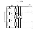
In the conveyance unit 56, in order to prevent an original sheet G conveyed along the conveyance path 22 from being wrinkled, when an original sheet G, which has been sent out by the sheet feed roller 40 to the conveyance path 22, starts being conveyed by the first and second conveyance rollers 44, 46, as shown in FIGS. 10A and 10B, the first conveyance rollers 44 apply the original sheet G with a driving force F1 for moving the original sheet G in the conveyance direction D2, the second conveyance rollers 46 apply the original sheet G with a driving force F3 for moving the original sheet G in the conveyance direction D2, and the sheet feed roller 40 applies the original sheet G with a restraining force F2 for restraining the original sheet G from moving in the conveyance direction D2.
As shown in FIG. 10A, a large sheet such as an A4-size sheet is conveyed by the three roller portions 44A-44C constituting each of the first conveyance rollers 44. Therefore, the large sheet G is subjected to at least three driving forces F1 and one restraining force F2 when the large sheet G is conveyed. Contrarily, as shown in FIG. 10B, a small sheet such as a business card is conveyed by the one roller portion 44B in each of the first conveyance rollers 44. Therefore, the small sheet G is subjected to one driving force F1 and one restraining force F2 when the small sheet G is conveyed. That is, the number of the roller portions in each of the first and second conveyance rollers 44, 46 that are used for conveying the small sheet G is fewer than that of the roller portions used for conveying the large sheet G. Therefore, in the total of the driving and restraining forces, the restraining force F2 has a greater impact on a small sheet than on a large sheet.
Therefore, at a separation timing when the original sheet G is separated from the sheet feed roller 40, disappearance of the restraining force F2 of the sheet feed roller 40 has a greater impact on a small sheet such as a business card indicated by a dashed line in FIG. 6 or a postcard indicated by a one-dot chain line, in comparison with on a large sheet such as an A4-size sheet indicated by a two-dot chain line in FIG. 6. As a result, at the separation timing, the conveyance speed of the small sheet G is more likely to increase instantaneously than that of the large sheet.
Among the small sheets, a sheet G of a first sheet type, whose sheet length is shorter than the second conveyance distance L2, such as a business card indicated by a dashed line in FIG. 6 separates away from the sheet feed roller 40 before the original sheet G reaches the position Z3. Contrarily, among the small sheets, a sheet G of a second sheet type, whose sheet length is greater than or equal to the second conveyance distance L2, such as a postcard indicated by a one-dot chain line in FIG. 6 separates away from the sheet feed roller 40 after the sheet G reaches the position Z3.
That is, at the separation timing, the second sheet-type original sheet G is conveyed by both of the first conveyance rollers 44 and the second conveyance rollers 46. Contrarily, at the separation timing, the first sheet-type original sheet G is conveyed only by the first conveyance rollers 44.
As shown in FIG. 10A, at the separation timing, an original sheet G of the second sheet type whose sheet length is longer than or equal to the second conveyance distance L2 receives a driving force F1 from the first conveyance rollers 44, and a driving force F3 from the second conveyance rollers 46. As shown in FIG. 10B, at the separation timing, an original sheet G of the first sheet type whose sheet length is less than the second conveyance distance L2 does not receive the driving force F3 from the second conveyance rollers 46. Accordingly, at the separation timing, the first sheet-type original sheet G is subjected to a smaller driving force than the second sheet-type original sheet G is. So, disappearance of the restraining force F2 at the separation timing has a greater impact on the first sheet-type original sheet G in comparison with on the second sheet-type original sheet G.
Therefore, at the separation timing, the conveyance speed of the first sheet-type original sheet G is more likely to increase instantaneously than that of the second sheet-type original sheet G. As a result, those regions of the original sheet G that are positioned at the reading positions Y1 and Y2 at the separation timing may possibly not be read by the CISs 30 and 32.
Thus, some regions of the original sheet G may possibly not be read depending on whether the sheet length of the original sheet G is shorter than the second conveyance distance L2. So, according to the present embodiment, the conveyance reading process described below includes a process of decreasing the conveyance speed of the original sheet G at the separation timing dependently on the sheet length of the original sheet G to be read.
3. Conveyance Reading Process
The following describes the conveyance reading process for an original sheet G with reference to FIGS. 4 to 7. According to the present embodiment, a front surface of an original sheet G is read by the first CIS 30. FIG. 4 is a flowchart showing the conveyance reading process that the CPU 20 performs in accordance with a prescribed program. The CPU 20 starts the process after the CPU 20 confirms by using the front sensor 13 that an original sheet G has been placed on the sheet feed tray 2 and a conveyance reading instruction for the original sheet G is inputted by a user through the operation unit 11.
After starting the conveyance reading process, the CPU 20 receives reading settings, such as a type of the original sheet G and a surface of the original sheet G to be read, which have been inputted by the user together with the conveyance reading instruction (S2). Then, the CPU 20 checks the state of the tray plate detection sensor 15 and sheet size detection sensor 16. More specifically, the CPU 20 first checks whether the tray plate detection sensor 15 is being ON. If the tray plate detection sensor 15 is being ON (S4: YES), i.e. if the discharge tray plate 54 is in the closed state, the CPU 20 detects that the original sheet G is to be conveyed along the U path 22B.
Then, the CPU 20 checks whether the sheet size detection sensor 16 is being ON (S6). If the sheet size detection sensor 16 is being ON (S6: YES), the state of the tray plate detection sensor 15 is consistent with the state of the sheet size detection sensor 16 because it is known that the original sheet G to be conveyed along the U path 22B is a large sheet. In this case, the CPU 20 turns ON a U path flag, indicating that the original sheet G is to be conveyed along the U path 22B (S10). Then, the CPU 20 performs a reading process described later (S18).
On the other hand, if the sheet size detection sensor 16 is being OFF (S6: NO), the CPU 20 detects that the original sheet G to be conveyed along the U path 22B is a small sheet. If a small sheet is conveyed along the U path 22B, the sheet is apt to be jammed in a curved portion along the periphery of one of the second conveyance rollers 46 on the U path 22B. So, the CPU 20 controls the display unit 12 to display an error message saying, “Open the discharge tray plate because the discharge tray plate is closed,” before starting to convey the original sheet G (S12). Then, the CPU 20 ends the conveyance reading process.
If the tray plate detection sensor 15 is OFF (S4: NO), i.e. if the discharge tray plate 54 is in the opened state, the CPU 20 detects that the original sheet G is to be conveyed along the S path 22A. Then, the CPU 20 checks whether the sheet size detection sensor 16 is being ON (S8). If the sheet size detection sensor 16 is being OFF (S8: NO), the state of the tray plate detection sensor 15 is consistent with the state of the sheet size detection sensor 16 because it is known that the original sheet G to be conveyed along the S path 22A is a small sheet. In this case, the CPU 20 turns ON an S path flag, indicating that the original sheet G is to be conveyed along the S path 22A (S14). Then, the CPU 20 performs the reading process (S18).
On the other hand, if the sheet size detection sensor 16 is ON (S8: YES), the CPU 20 detects that the original sheet G to be conveyed along the S path 22A is a large sheet. If a large sheet is conveyed along the S path 22A, the sheet G cannot be discharged onto the sheet discharge tray 4B, and becomes jammed. Therefore, the CPU 20 controls the display unit 12 to display an error message saying, “Close the discharge tray plate because the discharge tray plate is opened,” before starting to convey the original sheet G (S16). Then, the CPU 20 ends the conveyance reading process.
The following describes the reading process. FIG. 5 is a flowchart showing the reading process. In the reading process, the CPU 20 first instructs the conveyance unit 56 to convey an original sheet G (S22). At this time, the CPU 20 conveys the original sheet G at a constant conveyance speed that is determined based on the reading settings detected in S2. Then, the CPU 20 reads, from the ROM 26, a conveyance reference distance LK corresponding to a sheet size of the sheet type that has been detected in S2 (S24). The CPU 20 regards the sheet size of the sheet type set in S2 as the sheet size of the original sheet G to be read.
After starting conveying the original sheet G, the CPU 20 uses the rear sensor 14 to detect the position of the original sheet G being conveyed (S26: NO). When the rear sensor 14 is turned ON, indicating that a leading edge of the original sheet G has reached the detection position Y4 (S26: YES), the CPU 20 further moves the original sheet G by a first step number PA that is equivalent to a distance between the detection position Y4 and the first reading position Y1 along the conveyance path 22 (S28). Then, the CPU 20 instructs the first CIS 30 to read the original sheet G (S30).
Then, the CPU 20 compares the sheet width of the sheet type set in S2, that is, the sheet width of the original sheet G with the width H0 of the center region MH that is stored in the ROM 26 (S32). If the sheet width of the original sheet G is greater than the width H0 of the center region MH (S32: YES), the CPU 20 determines that the original sheet G is a large sheet such as an A4-size sheet. In this case, the CPU 20 continues conveying the original sheet G at the constant conveyance speed that is determined based on the reading settings, while reading the original sheet G.
On the other hand, if the sheet width of the original sheet G is less than or equal to the width H0 of the center region MH (S32: NO), the CPU 20 determines that the original sheet G is a small sheet such as a business card or postcard. If it is determined that the original sheet G is a small sheet, the CPU 20 further compares the sheet length of the sheet type set in S2, that is, the sheet length of the original sheet G with the first conveyance distance L1 and second conveyance distance L2 that are stored in the ROM 26 (S34).
If the sheet length of the original sheet G is greater than or equal to both of the first conveyance distance L1 and the second conveyance distance L2 (S34: NO), the CPU 20 determines that the original sheet G is of the second sheet type. In this case, as in the case where the CPU 20 determines that the original sheet G is a large sheet, the CPU 20 continues conveying the original sheet G at the constant conveyance speed that is determined based on the reading settings, while reading the original sheet G.
If the sheet length of the original sheet G is greater than or equal to the first conveyance distance L1 but less than the second conveyance distance L2 (S34: YES), the CPU 20 determines that the original sheet G is of the first sheet type. If it is determined that the original sheet G is of the first sheet type, the CPU 20 performs a process (S36 to S42) of outputting a conveyance stop instruction to the conveyance unit 56 in order to decrease the conveyance speed of the original sheet G at the separation timing.
More specifically, when the original sheet G has moved by the conveyance reference distance LK that is read in S24 after the rear sensor 14 turned ON (S36: YES), the CPU 20 outputs the conveyance stop instruction (S38). As described above, the conveyance reference distance LK is set to a distance that is determined by subtracting the third conveyance distance L3 from the sheet length of the original sheet G. Therefore, a timing at which the conveyance stop instruction is outputted substantially coincides with the separation timing at which the original sheet G separates from the sheet feed roller 40. More specifically, a position Z5 (See FIG. 2) where the original sheet G separates from the sheet feed roller 40 is slightly on the downstream side of the position Z1 where the sheet feed roller 40 is placed. Therefore, the timing at which the conveyance stop instruction is outputted is just ahead of the separation timing (See FIG. 7).
As shown in FIG. 7, upon receipt of the conveyance stop instruction outputted from the CPU 20, the conveyance unit 56 decreases the conveyance speed of the original sheet G. As a result, the conveyance speed at the separation timing becomes slower than the constant conveyance speed that is determined based on the reading settings. The CPU 20 continues reading the original sheet G even while the conveyance speed is being decreased. In the ROM 26, a speed reduction table is stored. The speed reduction table shows sub-scanning magnifications which represent enlargement or reduction ratios that should be applied onto read data acquired by the CISs 30 and 32 in the sub-scanning direction D2 while the conveyance speed is decreased. In other words, the speed reduction table shows how the sub-scanning magnifications should be modified at a time when the conveyance speed is decreased. So, when the conveyance speed is decreased, the CPU 20 continues reading the original sheet G by using the speed reduction table.
The CPU 20 monitors, through the conveyance unit drive circuit 28, whether the conveyance unit 56 is stopped, that is, whether the conveyance speed of the original sheet G becomes zero (S40: NO). When the conveyance unit 56 is stopped (S40: YES), the CPU 20 outputs a conveyance drive instruction to start driving the conveyance unit 56 again (S42).
As shown in FIG. 7, after the conveyance drive instruction is outputted, the conveyance speed of the original sheet G rises until the conveyance speed reaches the constant conveyance speed that is determined based on the reading settings. The CPU 20 continues reading the original sheet G even while the conveyance speed is increased. In the ROM 26, a speed increase table is also stored. The speed increase table shows sub-scanning magnifications which represent enlargement or reduction ratios that should be applied onto read data acquired by the CISs 30 and 32 in the sub-scanning direction D2 while the conveyance speed is increased. In other words, the speed increase table shows how the sub-scanning magnifications should be modified at a time when the conveyance speed is increased. So, when the conveyance speed is increased, the CPU 20 continues reading the original sheet G by using the speed increase table.
The CPU 20 continues reading the original sheet G until the rear sensor 14 is turned OFF (S44: NO). When the rear sensor 14 is turned OFF, indicating that a conveyance-direction trailing edge of the original sheet G has reached the detection position Y4 (S44: YES), the CPU 20 further moves the original sheet G by the first step number PA by using the conveyance unit 56 (S46), and stops reading the surface of the original sheet G (S48).
Then, the CPU 20 uses the front sensor 13 to detect whether or not there is any original sheet G left on the sheet feed tray 2 to read (S50). If there is some original sheet G left to read (S50: YES), the CPU 20 repeats the process of S26 and subsequent processes. If there is no original sheet G left to read (S50: NO), the CPU 20 discharges the original sheet G onto a sheet discharge tray 4A or 4B corresponding to the sheet size thereof and stops conveying the original sheet G (S52), and ends the reading process and the conveyance reading process.
4. Operations of the Present Embodiment
(1) The image reading apparatus 1 of the present embodiment determines whether the original sheet G is of the first or second sheet type. If the image reading apparatus 1 determines that the original sheet G is of the first sheet type, the conveyance speed of the original sheet G at the separation timing is made slower than that of another original sheet G that is determined to be of the second sheet type. The sheet length of the first sheet-type original sheet G is less than the second conveyance distance L2. So, at the separation timing, the first sheet-type original sheet G is not in contact with the second conveyance rollers 46. Therefore, compared with the second sheet-type original sheet G whose sheet length is greater than or equal to the second conveyance distance L2 and which is in contact with the second conveyance rollers at the separation timing, the conveyance speed of the first sheet-type original sheet G is more likely to rise at the separation timing.
So, in the image reading apparatus, the conveyance speed of the first sheet-type original sheet G is made slower at the separation timing than that of the second sheet-type original sheet G. Because the conveyance speed is made slower, even if the conveyance speed is increased instantaneously, a maximum speed that the conveyance speed can reach becomes slower than the case where the conveyance speed is not made slower. So, the distance the original sheet G is conveyed due to the instantaneous increase of the conveyance speed is restrained to a shorter length. Accordingly, when the CPU 20 controls the CISs 30 and 32 to scan the original sheet G at prescribed time intervals in the sub-scanning direction D2, occurrence of such a region that cannot be read because the original sheet G is conveyed a greater distance than planned, or such a region where image quality of read data becomes low can be restrained.
(2) In order to decrease the conveyance speed of the first sheet-type original sheet G at the separation timing, the image reading apparatus 1 of the present embodiment outputs the conveyance stop instruction. Therefore, the conveyance speed of the original sheet can be made slower in a limited period of time around the separation timing. The image reading apparatus 1 of the present embodiment outputs the conveyance stop instruction at almost the separation timing, or more specifically at a timing that is just ahead of the separation timing. Therefore, decrease in the image quality of read data due to decrease in the conveyance speed can be restrained during a period of time from when a process of reading the original sheet G is started until the separation timing.
(3) Before determining whether the original sheet G is of the first or second sheet type, the image reading apparatus 1 of the present embodiment determines whether the original sheet G is a small or large sheet. If the original sheet G is a small sheet, the image reading apparatus 1 then determines whether the original sheet G is of the first or second sheet type. The sheet width of the small sheet is less than the width H0 of the center region MH. So, at the separation timing, the small sheet is in contact with only one roller portion among the three roller portions constituting each of the first conveyance rollers 44. Therefore, the conveyance speed of a small sheet is more likely to rise at the separation timing, in comparison with a large sheet whose sheet width is greater than the width H0 of the center region MH and therefore which is in contact with all of the three roller portions constituting each of the first conveyance rollers 44 at the separation timing.
So, for a large sheet whose conveyance speed is relatively unlikely to rise, the image reading apparatus does not determine whether the sheet G is of a first or second sheet type. Only for a small sheet whose conveyance speed is relatively likely to rise, the image reading apparatus determines whether the sheet G is of the first or second sheet type. Therefore, only for an original sheet G whose conveyance speed is likely to rise due to its sheet size, rise in the conveyance speed is selectively suppressed. Therefore, it is possible to effectively restrain occurrence of: a region that cannot be read; or a region where the image quality of read data is low.
(4) Based on the reading settings that are detected prior to the reading process, the image reading apparatus 1 of the present embodiment detects the sheet size of an original sheet G to be read. Therefore, in the reading process, the image reading apparatus 1 determines, based on the detected sheet size, whether the original sheet G is a small or large sheet, and whether the original sheet G is of the first or second sheet type.
Second Embodiment
A second embodiment will be described with reference to FIGS. 4 and 8. The present embodiment is different from the first embodiment in that, in the reading process of the present embodiment, in order to decrease the conveyance speed of the first sheet-type original sheet G at the separation timing, the conveyance speed during the entire conveyance period of the sheet G, which includes the separation timing, is lowered compared with that of the second sheet-type original sheet G. In the following description, the same contents as those of the first embodiment will not be described again.
1. Conveyance Reading Process
As shown in FIG. 4, after starting the conveyance reading process, the CPU 20 receives the reading settings along with the conveyance reading instruction (S2). Also in the present embodiment, the reading settings are set so that the front surface of an original sheet G is to be read. The CPU 20 then performs the process of S4 and the subsequent processes, and executes the reading process of S18 if the judging result in S6 is affirmative or the judging result in S8 is negative.
FIG. 8 is a flowchart showing the reading process of the present embodiment. In the reading process, the CPU 20 first compares the sheet width of the sheet type set in S2 with the width H0 of the center region MH that is stored in the ROM 26 (S62). If the sheet width of the original sheet G is greater than the width H0 of the center region MH (S62: YES), the CPU 20 determines that the original sheet G is a large sheet such as an A4-size sheet. In this case, the CPU 20 reads resolution from the reading settings detected in S2, and compares the read out resolution with a predetermined reference resolution (S64, S66). In this example, the reference resolution is equal to 600 dpi.
If the read out resolution is equal to the reference resolution (S64: YES), the CPU 20 sets a second conveyance speed as the conveyance speed of the original sheet G (S68). If the read resolution is greater than the reference resolution (S64: NO, S66: NO), the CPU 20 sets a third conveyance speed as the conveyance speed of the original sheet G (S70). The third conveyance speed is slower than the second conveyance speed. If the read resolution is less than the reference resolution (S64: NO, S66: YES), the CPU 20 sets a first conveyance speed as the conveyance speed of the original sheet G (S72). The first conveyance speed is faster than the second conveyance speed.
If the sheet width of the original sheet G is less than or equal to the width H0 of the center region MH (S62: NO), the CPU 20 determines that the original sheet G is a small sheet such as a business card or postcard. If it is determined that the original sheet G is a small sheet, the CPU 20 further compares the sheet length of the sheet type set in S2 with the first conveyance distance L1 and second conveyance distance L2 that are stored in the ROM 26 (S74).
If the sheet length of the original sheet G is greater than or equal to both of the first conveyance distance L1 and the second conveyance distance L2 (S74: NO), the CPU 20 determines that the original sheet G is of the second sheet type. In this case, the CPU 20 sets the second conveyance speed as the conveyance speed of the original sheet G (S76).
If the sheet length of the original sheet G is greater than or equal to the first conveyance distance L1 but less than the second conveyance distance L2 (S74: YES), the CPU 20 determines that the original sheet G is of the first sheet type. If it is determined that the original sheet G is of the first sheet type, the CPU 20 sets a fourth conveyance speed as the conveyance speed of the original sheet G (S78). The fourth conveyance speed is slower than the second conveyance speed. Incidentally, as long as the fourth conveyance speed is slower than the second conveyance speed, the fourth conveyance speed may be faster, or slower, than the third conveyance speed.
After setting the conveyance speed of the original sheet G, the CPU 20 gives an instruction to convey the original sheet G at the set conveyance speed (S80). After giving the instruction to convey the original sheet G, the CPU 20 uses the rear sensor 14 to detect the position of the original sheet G being conveyed (S82: NO). When the rear sensor 14 is turned ON, indicating that a leading edge of the original sheet G has reached the detection position Y4 (S82: YES), the CPU 20 uses the conveyance unit 56 to further move the original sheet G by the first step number PA (S84). The CPU 20 then instructs the first CIS 30 to read the original sheet G (S86). Incidentally, after the process of reading the original sheet G is started, the same processes as those of the first embodiment are carried out, and therefore will not be described again.
2. Operation of the Present Embodiment
In order to decrease the conveyance speed of the first sheet-type original sheet G at the separation timing, the image reading apparatus 1 of the present embodiment sets conveyance speeds for the first sheet-type original sheet G and the second sheet-type original sheet G individually such that the conveyance speed of the first sheet-type original sheet G is slower than the conveyance speed of the second sheet-type original sheet G. Therefore, over the entire conveyance period of time including the separation timing, the conveyance speed of the first sheet-type original sheet G is kept slower than the conveyance speed of the second sheet-type original sheet G. Moreover, occurrence of changes in the conveyance speed of the original sheet G can be restrained during the conveyance period.
Third Embodiment
A third embodiment will be described with reference to FIG. 9. The present embodiment is different from the first embodiment in the following points: That is, in the reading process according to the first embodiment, the sheet size of the original sheet G is detected from the reading settings. Contrarily, in the reading process according to the present embodiment, the sheet size of the original sheet G is detected from leading-edge read data of the original sheet G that is acquired by reading a leading edge of the original sheet G. In the following description, the same contents as those of the first embodiment will not be described again.
Also according to the present embodiment, the reading settings are set so that the front surface of an original sheet G is to be read. Moreover, according to the present embodiment, original sheets G to be read by the image reading apparatus 1 are so-called standard-size sheets G such as business cards, postcards, and A4-size sheets, for which sheet lengths can be estimated based on sheet widths.
1. Conveyance Reading Process
FIG. 9 is a flowchart showing the reading process of the present embodiment. In the reading process, after instructing the first CIS 30 to read the original sheet G (S30), the CPU 20 controls the first CIS 30 to read a predetermined reading range of the original sheet G that is positioned at a leading-edge of the original sheet G and to acquire the leading-edge read data (S92). The CPU 20 detects the sheet width of the original sheet G based on the acquired leading-edge read data, and estimates the sheet length of the original sheet G based on the sheet width (S94).
The CPU 20 compares the sheet width of the original sheet G that is detected in S94 with the width H0 of the center region MH that is stored in the ROM 26, and determines whether the original sheet G is a large or small sheet (S96). If it is determined that the original sheet G is a small sheet (S96: NO), the CPU 20 then compares the sheet length of the original sheet G that is estimated in S94 with the first conveyance distance L1 and second conveyance distance L2 that are stored in the ROM 26, and determines whether the original sheet G is of the first or second sheet type (S98). Incidentally, the subsequent processes are the same as those of the first embodiment, and therefore will not be described again.
2. Operations of the Present Embodiment
The image reading apparatus 1 of the present embodiment detects the sheet width of the original sheet G to be read based on the leading-edge read data that is acquired by reading the conveyance-direction leading edge of the original sheet G, thereby detecting the sheet size. Since the sheet size is detected from the leading-edge read data that is acquired from the original sheet G to be read, an accurate determination can be made as to whether the original sheet G is a small or large sheet, or whether the original sheet G is of the first or second sheet type.
Other Embodiments
While the invention has been described in detail with reference to the embodiments thereof, it would be apparent to those skilled in the art that various changes and modifications may be made therein without departing from the spirit of the invention.
(1) For example, according to the above-described embodiments, the image reading apparatus 1 has a scanner function. However, the present invention is not limited to this example. For example, the present invention may be applied to a multifunction peripheral having a printer function, copy function, facsimile function, and other functions.
(2) According to the above embodiments, the image reading apparatus 1 has a single CPU 20 that executes various processes in the conveyance reading process. However, the present invention is not limited to this example. For example, a plurality of CPUs may be employed each for executing each part in the conveyance reading process. Or, one or more hardware circuit such as ASIC (Application Specific Integrated Circuit) may be employed for executing each part in the conveyance reading process. Or, one or more CPU and one or more ASIC may be employed to execute each part in the conveyance reading process.
(3) The program executed by the CPU 20 is not necessarily stored in the ROM 26. The program may be stored in the CPU 20 or any other storage device.
(4) According to the above embodiments, based on the positional relationship between the conveyance rollers 44 and 46 of the image reading apparatus 1, an A4-size sheet serves as an example of the large sheet, a business card and a postcard serve as examples of the small sheet, and a business card serves as an example of the first sheet-type original sheet G, and a postcard serves as an example of the second sheet-type original sheet G. However, the present invention is not limited to this example. For example, if the positional relationship between the conveyance rollers 44 and 46 is changed, a postcard may belong to the first sheet-type original sheets G, and an A4-size sheet may belong to the small sheet.
(5) According to the above embodiments, in determining whether the original sheet G is a small or large sheet, the size of the original sheet is detected from the reading settings or the leading-edge read data. However, the present invention is not limited to this example. For example, based on the state of the sheet size detection sensor 16, a determination may be made as to whether the original sheet G is a small or large sheet. If the state of the sheet size detection sensor 16 is consistent with the state of the tray plate detection sensor 15, a determination may be made as to whether the original sheet G is a small or large sheet based on the state of the tray plate detection sensor 15, instead of the state of the sheet size detection sensor 16.
(6) According to the above embodiments, first a determination is made as to whether the original sheet G is a small or large sheet; and, if it is determined that the original sheet G is a small sheet, then a determination is made as to whether the original sheet G is of the first or second sheet type. However, the present invention is not limited to this example. For example, the determination as to whether the original sheet G is a small or large sheet may not be executed, and the determination as to whether the original sheet G is of the first or second sheet type may be applied onto all the original sheets to be read.
(7) According to the above embodiments, in order to decrease the conveyance speed of the first sheet-type original sheet G at the separation timing, the conveyance stop instruction is outputted. However, the present invention is not limited to this example. For example, instead of the conveyance stop instruction, a speed reduction instruction may be outputted to decrease the conveyance speed of the first sheet-type original sheet G at the separation timing. It is noted that the conveyance stop instruction in the first embodiment serves to decrease the conveyance speed before finally stopping the conveyance. So, it can be said that the conveyance stop instruction in the first embodiment serves also as an example of the speed reduction instruction.

Claims (7)

What is claimed is:
1. An image reading apparatus, comprising:
a sheet feed tray;
a supply roller configured to rotate while being in contact with an original sheet placed on the sheet feed tray and to send out the original sheet one sheet by one sheet to a conveyance path;
a conveyance unit including a first conveyance roller and a second conveyance roller and configured to convey, along the conveyance path, the original sheet that has been sent out by the supply roller to the conveyance path, the conveyance unit conveying the original sheet by using the first conveyance roller and the second conveyance roller in succession in this order;
a discharged-sheet receiving unit, into which the original sheet that has been conveyed by the conveyance unit is discharged;
an image reading unit disposed at a reading position along the conveyance path between the first conveyance roller and the second conveyance roller and configured to read an image, in a main scanning direction, from the original sheet conveyed by the conveyance unit at the reading position; and
a control device configured to:
judge whether the original sheet is either one of a first sheet type, whose sheet length in a conveying direction along the conveyance path is longer than or equal to a first conveyance distance and shorter than a second conveyance distance, and a second sheet type, whose sheet length in the conveying direction along the conveyance path is longer than or equal to the second conveyance distance, the first conveyance distance being a distance between the first conveyance roller and the second conveyance roller along the conveyance path, the second conveyance distance being a distance between the supply roller and the second conveyance roller along the conveyance path;
control the conveyance unit to convey the original sheet such that if the original sheet is of the first sheet type,
the original sheet starts being conveyed at a prescribed conveyance speed,
the conveyance speed is changed to a value smaller than the prescribed conveyance speed at a timing before a separation timing when the original sheet separates away from the supply roller, and
the conveyance speed is returned to the prescribed conveyance speed at a timing after the separation timing; and
read, by using the image reading unit, an image from the original sheet that is conveyed by the conveyance unit through the control.
2. The image reading apparatus as claimed in claim 1,
wherein if the original sheet is of the first sheet type, the control device outputs to the conveyance unit a conveyance stop instruction to stop conveyance at a timing immediately before the separation timing, and outputs to the conveyance unit a conveyance restart instruction to restart conveyance at a timing when the conveyance speed reaches zero.
3. The image reading apparatus as claimed in claim 1, wherein
the supply roller is disposed in part of a conveyance region of the conveyance path in the main scanning direction,
the first conveyance roller includes a plurality of roller portions arranged in the entire conveyance region in the main scanning direction,
the control device is further configured to judge whether the original sheet is of a narrow sheet type or a wide sheet type, the number of a roller portion that constitutes the first conveyance roller and that conveys an original sheet of the narrow sheet type being smaller than or equal to a reference number, the number of a roller portion that constitutes the first conveyance roller and that conveys an original sheet of the wide sheet type being greater than the reference number,
the control device is configured to judge whether the original sheet is of the first sheet type or the second sheet type if the original sheet is determined to be of the narrow sheet type.
4. The image reading apparatus as claimed in claim 1, wherein
the discharged-sheet receiving unit includes a first sheet discharge tray and a second sheet discharge tray,
the conveying path diverges into a first conveyance path and a second conveyance path at a position downstream of the second conveyance roller in the conveying direction,
the conveyance unit conveys an original sheet of the narrow sheet type using the first conveyance path to the first sheet discharge tray, and conveys an original sheet of the wide sheet type using the second conveyance path to the second sheet discharge tray.
5. The image reading apparatus as claimed in claim 1, further comprising an operation unit configured to allow a user to input data indicative of a sheet size of the original sheet, and
wherein the control device is configured to detect a sheet length of the original sheet based on the inputted data indicative of the sheet size, thereby determining the sheet type of the original sheet.
6. The image reading apparatus as claimed in claim 1,
wherein
the original sheet has either one of a plurality of different standard sizes whose sheet lengths are longer than a third conveyance distance, the third conveyance distance being a distance between the supply roller and the reading position along the conveyance path, and
the control device is configured to detect the sheet length of the original sheet based on leading-edge read data acquired by the reading unit reading a leading edge of the original sheet in the conveying direction, thereby determining the sheet type.
7. The image reading apparatus as claimed in claim 1, wherein the control device controls the conveyance unit to convey the original sheet at the prescribed conveyance speed if the original sheet is of the second sheet type.
US14/039,490 2012-11-20 2013-09-27 Image reading apparatus that reads original sheet while conveying the same Active US8950749B2 (en)

Applications Claiming Priority (2)

Application Number Priority Date Filing Date Title
JP2012254696A JP6089619B2 (en) 2012-11-20 2012-11-20 Image reading device
JP2012-254696 2012-11-20

Publications (2)

Publication Number Publication Date
US20140138898A1 US20140138898A1 (en) 2014-05-22
US8950749B2 true US8950749B2 (en) 2015-02-10

Family

ID=50727204

Family Applications (1)

Application Number Title Priority Date Filing Date
US14/039,490 Active US8950749B2 (en) 2012-11-20 2013-09-27 Image reading apparatus that reads original sheet while conveying the same

Country Status (2)

Country Link
US (1) US8950749B2 (en)
JP (1) JP6089619B2 (en)

Cited By (2)

* Cited by examiner, † Cited by third party
Publication number Priority date Publication date Assignee Title
US10951785B2 (en) * 2019-03-06 2021-03-16 Pfu Limited Image reading apparatus
US11498788B2 (en) * 2019-06-05 2022-11-15 Canon Kabushiki Kaisha Sheet conveyance apparatus, document reading apparatus and image forming apparatus

Families Citing this family (5)

* Cited by examiner, † Cited by third party
Publication number Priority date Publication date Assignee Title
TWI569982B (en) * 2014-04-16 2017-02-11 虹光精密工業股份有限公司 Duplex peripheral capable of processing large-size and small-size documents
US10027831B2 (en) * 2015-11-16 2018-07-17 Ricoh Company, Ltd. Image reading unit
JP6946919B2 (en) 2017-10-16 2021-10-13 セイコーエプソン株式会社 Image reader
JP2021136596A (en) * 2020-02-27 2021-09-13 キヤノン株式会社 Image forming system, and image reading device
JP2022049270A (en) 2020-09-16 2022-03-29 セイコーエプソン株式会社 Image reading device

Citations (11)

* Cited by examiner, † Cited by third party
Publication number Priority date Publication date Assignee Title
US4713674A (en) * 1985-04-04 1987-12-15 Oce-Nederland B.V. Exposure device for sheets
US4714941A (en) * 1985-04-16 1987-12-22 Sharp Kabushiki Kaisha Copying apparatus having a controlled scanning speed according to a copying magnification
JPH11127301A (en) 1997-10-21 1999-05-11 Matsushita Electric Ind Co Ltd Image reader
US5915158A (en) * 1995-12-28 1999-06-22 Nisca Corporation Variable-timing automatic document feeding device and method
JPH11227976A (en) 1998-02-16 1999-08-24 Canon Inc Sheet carrying roller, image reading device and image forming device
US6851802B2 (en) 2002-05-02 2005-02-08 Brother Kogyo Kabushiki Kaisha Image forming device including mechanism to lock cover
US20090027740A1 (en) * 2007-07-24 2009-01-29 Samsung Electronics Co., Ltd Read device, image forming apparatus and method of controlling the image forming apparatus
US8121510B2 (en) * 2008-07-15 2012-02-21 Riso Kagaku Corporation Printer with duplex circulation route speed control
JP2012182662A (en) 2011-03-01 2012-09-20 Canon Electronics Inc Image reading device, control method therefor, and program
US8693072B2 (en) * 2011-06-30 2014-04-08 Brother Kogyo Kabushiki Kaisha Image reading apparatus
US20140138897A1 (en) * 2012-11-20 2014-05-22 Brother Kogyo Kabushiki Kaisha Image reading apparatus having conveyance rollers conveying original sheet

Family Cites Families (1)

* Cited by examiner, † Cited by third party
Publication number Priority date Publication date Assignee Title
JP4387650B2 (en) * 2002-09-30 2009-12-16 キヤノン株式会社 Image reading device

Patent Citations (12)

* Cited by examiner, † Cited by third party
Publication number Priority date Publication date Assignee Title
US4713674A (en) * 1985-04-04 1987-12-15 Oce-Nederland B.V. Exposure device for sheets
US4714941A (en) * 1985-04-16 1987-12-22 Sharp Kabushiki Kaisha Copying apparatus having a controlled scanning speed according to a copying magnification
US5915158A (en) * 1995-12-28 1999-06-22 Nisca Corporation Variable-timing automatic document feeding device and method
JPH11127301A (en) 1997-10-21 1999-05-11 Matsushita Electric Ind Co Ltd Image reader
JPH11227976A (en) 1998-02-16 1999-08-24 Canon Inc Sheet carrying roller, image reading device and image forming device
US6851802B2 (en) 2002-05-02 2005-02-08 Brother Kogyo Kabushiki Kaisha Image forming device including mechanism to lock cover
US7384042B2 (en) 2002-05-02 2008-06-10 Brother Kogyo Kabushiki Kaisha Image forming device including mechanism to lock cover
US20090027740A1 (en) * 2007-07-24 2009-01-29 Samsung Electronics Co., Ltd Read device, image forming apparatus and method of controlling the image forming apparatus
US8121510B2 (en) * 2008-07-15 2012-02-21 Riso Kagaku Corporation Printer with duplex circulation route speed control
JP2012182662A (en) 2011-03-01 2012-09-20 Canon Electronics Inc Image reading device, control method therefor, and program
US8693072B2 (en) * 2011-06-30 2014-04-08 Brother Kogyo Kabushiki Kaisha Image reading apparatus
US20140138897A1 (en) * 2012-11-20 2014-05-22 Brother Kogyo Kabushiki Kaisha Image reading apparatus having conveyance rollers conveying original sheet

Cited By (2)

* Cited by examiner, † Cited by third party
Publication number Priority date Publication date Assignee Title
US10951785B2 (en) * 2019-03-06 2021-03-16 Pfu Limited Image reading apparatus
US11498788B2 (en) * 2019-06-05 2022-11-15 Canon Kabushiki Kaisha Sheet conveyance apparatus, document reading apparatus and image forming apparatus

Also Published As

Publication number Publication date
US20140138898A1 (en) 2014-05-22
JP2014103560A (en) 2014-06-05
JP6089619B2 (en) 2017-03-08

Similar Documents

Publication Publication Date Title
US8950749B2 (en) Image reading apparatus that reads original sheet while conveying the same
US9013764B2 (en) Reading apparatus that reads original sheet while conveying the same
US11097920B2 (en) Sheet folding apparatus and image forming system incorporating same
US10574851B2 (en) Image scanning apparatus
EP1773042A2 (en) Document reading apparatus
US10911630B2 (en) Image reading apparatus
US8538309B2 (en) Printing apparatus
JP2014150322A5 (en)
JP2014103560A5 (en)
US8991821B2 (en) Image reading apparatus having conveyance rollers conveying original sheet
JP6572674B2 (en) Image reading device
JP7229723B2 (en) IMAGE PROCESSING DEVICE, CONTROL METHOD THEREOF, AND PROGRAM
JP2014103561A5 (en)
US8636276B2 (en) Image reading device capable of reading skew sheet
JP2011111317A (en) Sheet feeding device
US20100001453A1 (en) Document reader
US8864269B2 (en) Printing apparatus and control method thereof
JP2010016682A (en) Document reader, and image forming apparatus
US9745158B2 (en) Conveying apparatus and printing apparatus
JP7247029B2 (en) Paper transport device
JP7207979B2 (en) Document feeder, control method and control program
WO2022153497A1 (en) Medium conveyance device, control method, and control program
JP2011020834A (en) Sheet processing device and method
JP6179797B2 (en) Image reading device
US20120250113A1 (en) Image processing device having sheet conveying mechanism

Legal Events

Date Code Title Description
AS Assignment

Owner name: BROTHER KOGYO KABUSHIKI KAISHA, JAPAN

Free format text: ASSIGNMENT OF ASSIGNORS INTEREST;ASSIGNORS:MAEDA, TAKASHI;TAKAHATA, MUNEAKI;OSAKABE, YOSHINORI;AND OTHERS;SIGNING DATES FROM 20141210 TO 20141211;REEL/FRAME:034577/0776

STCF Information on status: patent grant

Free format text: PATENTED CASE

MAFP Maintenance fee payment

Free format text: PAYMENT OF MAINTENANCE FEE, 4TH YEAR, LARGE ENTITY (ORIGINAL EVENT CODE: M1551)

Year of fee payment: 4

MAFP Maintenance fee payment

Free format text: PAYMENT OF MAINTENANCE FEE, 8TH YEAR, LARGE ENTITY (ORIGINAL EVENT CODE: M1552); ENTITY STATUS OF PATENT OWNER: LARGE ENTITY

Year of fee payment: 8