US8948200B2 - Method and system for providing secure communications between proxy servers in support of interdomain traversal - Google Patents
Method and system for providing secure communications between proxy servers in support of interdomain traversal Download PDFInfo
- Publication number
- US8948200B2 US8948200B2 US13/454,837 US201213454837A US8948200B2 US 8948200 B2 US8948200 B2 US 8948200B2 US 201213454837 A US201213454837 A US 201213454837A US 8948200 B2 US8948200 B2 US 8948200B2
- Authority
- US
- United States
- Prior art keywords
- proxy server
- endpoint
- domain
- sip
- network address
- Prior art date
- Legal status (The legal status is an assumption and is not a legal conclusion. Google has not performed a legal analysis and makes no representation as to the accuracy of the status listed.)
- Active, expires
Links
- 238000004891 communication Methods 0.000 title claims abstract description 131
- 238000000034 method Methods 0.000 title claims description 78
- 230000011664 signaling Effects 0.000 claims description 32
- 230000000977 initiatory effect Effects 0.000 claims description 15
- 238000013519 translation Methods 0.000 claims description 13
- 238000013459 approach Methods 0.000 abstract description 15
- 230000005540 biological transmission Effects 0.000 abstract description 9
- 230000006870 function Effects 0.000 description 42
- 238000010586 diagram Methods 0.000 description 38
- 230000008569 process Effects 0.000 description 33
- 230000001413 cellular effect Effects 0.000 description 32
- 238000007726 management method Methods 0.000 description 22
- 230000004044 response Effects 0.000 description 16
- 230000007246 mechanism Effects 0.000 description 11
- 238000006243 chemical reaction Methods 0.000 description 10
- 238000005516 engineering process Methods 0.000 description 10
- 230000027455 binding Effects 0.000 description 8
- 238000009739 binding Methods 0.000 description 8
- 239000003795 chemical substances by application Substances 0.000 description 8
- 238000001914 filtration Methods 0.000 description 7
- 230000003287 optical effect Effects 0.000 description 7
- 238000013478 data encryption standard Methods 0.000 description 6
- 230000000694 effects Effects 0.000 description 6
- 238000012545 processing Methods 0.000 description 6
- 238000013475 authorization Methods 0.000 description 5
- 230000008901 benefit Effects 0.000 description 4
- 230000010354 integration Effects 0.000 description 4
- 238000013507 mapping Methods 0.000 description 4
- 238000012546 transfer Methods 0.000 description 4
- 230000001960 triggered effect Effects 0.000 description 4
- 238000013461 design Methods 0.000 description 3
- 238000012544 monitoring process Methods 0.000 description 3
- 238000010079 rubber tapping Methods 0.000 description 3
- 230000003068 static effect Effects 0.000 description 3
- 239000013543 active substance Substances 0.000 description 2
- 238000001514 detection method Methods 0.000 description 2
- 238000005538 encapsulation Methods 0.000 description 2
- 230000003993 interaction Effects 0.000 description 2
- 238000013508 migration Methods 0.000 description 2
- 230000005012 migration Effects 0.000 description 2
- 238000010295 mobile communication Methods 0.000 description 2
- 238000011330 nucleic acid test Methods 0.000 description 2
- 230000008520 organization Effects 0.000 description 2
- 238000011144 upstream manufacturing Methods 0.000 description 2
- 238000010200 validation analysis Methods 0.000 description 2
- RYGMFSIKBFXOCR-UHFFFAOYSA-N Copper Chemical compound [Cu] RYGMFSIKBFXOCR-UHFFFAOYSA-N 0.000 description 1
- 230000009471 action Effects 0.000 description 1
- 239000008186 active pharmaceutical agent Substances 0.000 description 1
- 238000003491 array Methods 0.000 description 1
- 230000002567 autonomic effect Effects 0.000 description 1
- 230000006399 behavior Effects 0.000 description 1
- 238000003490 calendering Methods 0.000 description 1
- 239000000969 carrier Substances 0.000 description 1
- 230000010267 cellular communication Effects 0.000 description 1
- 230000008859 change Effects 0.000 description 1
- 238000012512 characterization method Methods 0.000 description 1
- 230000000295 complement effect Effects 0.000 description 1
- 239000012141 concentrate Substances 0.000 description 1
- 230000001276 controlling effect Effects 0.000 description 1
- 230000008878 coupling Effects 0.000 description 1
- 238000010168 coupling process Methods 0.000 description 1
- 238000005859 coupling reaction Methods 0.000 description 1
- 238000011161 development Methods 0.000 description 1
- 230000009977 dual effect Effects 0.000 description 1
- 230000002708 enhancing effect Effects 0.000 description 1
- 239000000835 fiber Substances 0.000 description 1
- 230000004907 flux Effects 0.000 description 1
- 239000011521 glass Substances 0.000 description 1
- 230000036541 health Effects 0.000 description 1
- 230000008676 import Effects 0.000 description 1
- 230000002452 interceptive effect Effects 0.000 description 1
- 238000011835 investigation Methods 0.000 description 1
- 239000004973 liquid crystal related substance Substances 0.000 description 1
- 238000012423 maintenance Methods 0.000 description 1
- 239000011159 matrix material Substances 0.000 description 1
- 238000012986 modification Methods 0.000 description 1
- 230000004048 modification Effects 0.000 description 1
- 230000037211 monthly cycles Effects 0.000 description 1
- 230000002853 ongoing effect Effects 0.000 description 1
- 230000002093 peripheral effect Effects 0.000 description 1
- 230000002085 persistent effect Effects 0.000 description 1
- 238000013439 planning Methods 0.000 description 1
- 238000011084 recovery Methods 0.000 description 1
- 230000001105 regulatory effect Effects 0.000 description 1
- 238000013468 resource allocation Methods 0.000 description 1
- 238000012216 screening Methods 0.000 description 1
- XLYOFNOQVPJJNP-UHFFFAOYSA-N water Substances O XLYOFNOQVPJJNP-UHFFFAOYSA-N 0.000 description 1
Images


Classifications
-
- H—ELECTRICITY
- H04—ELECTRIC COMMUNICATION TECHNIQUE
- H04L—TRANSMISSION OF DIGITAL INFORMATION, e.g. TELEGRAPHIC COMMUNICATION
- H04L65/00—Network arrangements, protocols or services for supporting real-time applications in data packet communication
- H04L65/1066—Session management
- H04L65/1101—Session protocols
-
- H04L29/06027—
-
- H04L29/125—
-
- H04L29/12537—
-
- H—ELECTRICITY
- H04—ELECTRIC COMMUNICATION TECHNIQUE
- H04L—TRANSMISSION OF DIGITAL INFORMATION, e.g. TELEGRAPHIC COMMUNICATION
- H04L61/00—Network arrangements, protocols or services for addressing or naming
- H04L61/09—Mapping addresses
- H04L61/25—Mapping addresses of the same type
- H04L61/2503—Translation of Internet protocol [IP] addresses
- H04L61/256—NAT traversal
- H04L61/2564—NAT traversal for a higher-layer protocol, e.g. for session initiation protocol [SIP]
-
- H—ELECTRICITY
- H04—ELECTRIC COMMUNICATION TECHNIQUE
- H04L—TRANSMISSION OF DIGITAL INFORMATION, e.g. TELEGRAPHIC COMMUNICATION
- H04L61/00—Network arrangements, protocols or services for addressing or naming
- H04L61/09—Mapping addresses
- H04L61/25—Mapping addresses of the same type
- H04L61/2503—Translation of Internet protocol [IP] addresses
- H04L61/256—NAT traversal
- H04L61/2578—NAT traversal without involvement of the NAT server
-
- H—ELECTRICITY
- H04—ELECTRIC COMMUNICATION TECHNIQUE
- H04L—TRANSMISSION OF DIGITAL INFORMATION, e.g. TELEGRAPHIC COMMUNICATION
- H04L65/00—Network arrangements, protocols or services for supporting real-time applications in data packet communication
- H04L65/10—Architectures or entities
- H04L65/102—Gateways
- H04L65/1023—Media gateways
- H04L65/103—Media gateways in the network
-
- H—ELECTRICITY
- H04—ELECTRIC COMMUNICATION TECHNIQUE
- H04L—TRANSMISSION OF DIGITAL INFORMATION, e.g. TELEGRAPHIC COMMUNICATION
- H04L65/00—Network arrangements, protocols or services for supporting real-time applications in data packet communication
- H04L65/10—Architectures or entities
- H04L65/102—Gateways
- H04L65/1033—Signalling gateways
- H04L65/104—Signalling gateways in the network
-
- H—ELECTRICITY
- H04—ELECTRIC COMMUNICATION TECHNIQUE
- H04L—TRANSMISSION OF DIGITAL INFORMATION, e.g. TELEGRAPHIC COMMUNICATION
- H04L65/00—Network arrangements, protocols or services for supporting real-time applications in data packet communication
- H04L65/10—Architectures or entities
- H04L65/102—Gateways
- H04L65/1043—Gateway controllers, e.g. media gateway control protocol [MGCP] controllers
-
- H—ELECTRICITY
- H04—ELECTRIC COMMUNICATION TECHNIQUE
- H04L—TRANSMISSION OF DIGITAL INFORMATION, e.g. TELEGRAPHIC COMMUNICATION
- H04L65/00—Network arrangements, protocols or services for supporting real-time applications in data packet communication
- H04L65/1066—Session management
- H04L65/1101—Session protocols
- H04L65/1108—Web based protocols, e.g. webRTC
-
- H04L65/608—
-
- H—ELECTRICITY
- H04—ELECTRIC COMMUNICATION TECHNIQUE
- H04L—TRANSMISSION OF DIGITAL INFORMATION, e.g. TELEGRAPHIC COMMUNICATION
- H04L65/00—Network arrangements, protocols or services for supporting real-time applications in data packet communication
- H04L65/60—Network streaming of media packets
- H04L65/65—Network streaming protocols, e.g. real-time transport protocol [RTP] or real-time control protocol [RTCP]
Definitions
- the present invention relates to communications, and more particularly, to transmitting a packetized voice call across different domains.
- IP Internet Protocol
- the attractive economics of IP telephony (stemming largely from the global connectivity and accessibility of the Internet) along with innovative productivity tools for users have triggered adoption of this technology by numerous businesses, organizations, enterprises and the like.
- this adoption primarily has been uncoordinated, and driven by the needs of the specific enterprise little regard to a “global” approach for IP telephony deployment.
- the prevailing IP telephony implementations have confined the particular enterprises, as to make communications outside the enterprise difficult and impractical.
- security concerns are an impediment to wide spread deployment of IP telephony systems.
- IP islands As enterprises implement Internet telephony as well as messaging systems and associated applications, closed communities of IP enabled users are created—i.e., “IP islands”. That is, because of systems and applications constraints and incompatibilities, these IP enable users are isolated, and thus, cannot readily communicate with each other. Moreover, as Internet Service Providers (ISPs), cable, and mobile network operators begin to provide Internet telephony services. The IP islands grow even larger into a “constellation” of non-connected communities. While such communities can in some cases be linked using the Public Switched Telephone Network (PSTN), the benefits of IP telephony—e.g., user presence, unified communications, user preference, and lower costs may be sacrificed.
- PSTN Public Switched Telephone Network
- IP telephony is subject to several constraints.
- users are required to have knowledge of whether an IP endpoint is available if the full capabilities of IP telephony are to be realized.
- the knowledge of whether there are multiple IP enabled devices is being used by the called party as well as how to reach such devices is needed.
- Another constraint is that a single IP “telephone” number is not available among the various IP enabled devices; instead, these devices utilize diverse and complex addresses.
- determining the identity of the calling party e.g., caller ID
- IP networks are vulnerable to a variety of security threats, which are non-existent in circuit-switched telephony networks.
- a method for providing packetized communication services includes receiving a request specifying a directory number for establishing a communication session from a first endpoint to a second endpoint, wherein the first endpoint is behind a first network address translator of a first domain, and the second endpoint is within a second domain.
- the method also includes communicating with a service provider network to determine a network address for communicating with the second endpoint based on the directory number, to determine existence of a second network address translator within the second domain, and to establish, if the network address can be determined, a media path between the first endpoint and the second endpoint based on the network address to support the communication session.
- the method includes establishing an encrypted session with a proxy server according to a cryptographic protocol to support the media path, the proxy server residing within the second domain.
- a network apparatus for supporting managed communication services.
- the apparatus includes a first communication interface configured to receive a request specifying a directory number for establishing a communication session from a first endpoint to a second endpoint, wherein the first endpoint is behind a first network address translator of a first domain, and the second endpoint is within a second domain.
- the apparatus includes a second communication interface configured to communicate with a service provider network to determine a network address for communicating with the second endpoint based on the directory number, to determine existence of a second network address translator within the second domain, and to establish, if the network address can be determined, a media path between the first endpoint and the second endpoint based on the network address to support the communication session.
- the apparatus includes a processor configured to establish an encrypted session with a proxy server according to a cryptographic protocol to support the media path, the proxy server residing within the second domain.
- a system for providing managed communication services includes an address server configured to receive a request for a network address for communicating with a destination endpoint based on a directory number, wherein the directory number is specified in a call establishment request to establish a communication session from a source endpoint behind a first network address translator of a first domain, and the destination endpoint is within a second domain.
- the system also includes a STUN (Simple Traversal of UDP (User Datagram Protocol)) server configured to support determination of existence of a second network address translator within the second domain.
- STUN Simple Traversal of UDP (User Datagram Protocol)
- the system includes a TURN (Traversal Using Relay NAT (Network Address Translation)) server configured to establish, if the network address can be determined, a media path between the source endpoint and the destination endpoint based on the network address to support the communication session.
- the media path includes an encrypted session between a first proxy server residing within the first domain and a second proxy server residing within the second domain.
- a method for providing packetized communication services includes transmitting a request to a near-end proxy server for establishing a communication session with a destination endpoint, wherein the request is transmitted through a first network address translator of a first domain, and the destination endpoint is within a second domain.
- the near-end proxy server is configured communicate with a service provider network to determine a network address for communicating with the second endpoint based on the directory number, to determine existence of a second network address translator within the second domain, and to establish, if the network address can be determined, a media path with the destination endpoint based on the network address to support the communication session.
- the method includes establishing an encrypted session with the near-end proxy server according to a cryptographic protocol to support the media path.
- FIG. 1 is a functional diagram of a communication system for supporting interconnectivity of disparate packetized voice networks, according to one embodiment of the present invention
- FIGS. 2A-2E are diagrams of a communication system and associated processes for providing interdomain traversal by utilizing secure proxy servers, according to one embodiment of the present invention
- FIG. 3 is a diagram of an exemplary architecture for supporting ENUM (Electronic Number) services in the system of FIG. 1 , according to one embodiment of the present invention
- FIG. 4 is a diagram of an exemplary Session Initiation Protocol (SIP)-to-SIP call flow, according to an embodiment of the present invention
- FIG. 5 is a diagram of an exemplary SIP-to-PSTN (Public Switched Telephone Network) call flow, according to an embodiment of the present invention
- FIG. 6 is a diagram of an architecture utilizing a centralized data store supporting communication among remote endpoints, according to an embodiment of the present invention
- FIG. 7 is a diagram of a wireless communication system for providing application mobility, according to one embodiment of the present invention.
- FIGS. 8A and 8B are diagrams of exemplary multimodal wireless and wired devices, according to various embodiments of the present invention.
- FIG. 9 is a diagram of a process for authentication and registration of a multimodal device in a data network, according to one embodiment of the present invention.
- FIG. 10 is a diagram of a process for establishing a call from a multimodal device to the PSTN, according to one embodiment of the present invention.
- FIG. 11 is a diagram of a process for establishing a call to a multimodal device from the PSTN, according to one embodiment of the present invention.
- FIG. 12 is a diagram of a process for cellular-to-IP mode switching during a call supported by the PSTN, according to one embodiment of the present invention.
- FIG. 13 is a diagram of a process for IP-to-cellular mode switching during a call supported by the PSTN, according to one embodiment of the present invention.
- FIG. 14 is a diagram of a process for call establishment by a multimodal device operating in cellular mode, according to one embodiment of the present invention.
- FIG. 15 is a diagram of a process for cellular-to-IP mode switching mid-call, according to one embodiment of the present invention.
- FIG. 16 is a diagram of an Operational Support System (OSS) architecture, according to one embodiment of the present invention.
- OSS Operational Support System
- FIG. 17 is a diagram of a financial system for supporting IP Interconnect service, according to one embodiment of the present invention.
- FIG. 18 is a diagram of a service assurance infrastructure components capable of supporting the Interconnect services, in accordance with an embodiment of the present invention.
- FIG. 19 is a diagram of a computer system that can be used to implement various embodiments of the present invention.
- IP Internet Protocol
- FIG. 1 is a functional diagram of a communication system for supporting interconnectivity of disparate packetized voice networks, according to one embodiment of the present invention.
- An IP interconnect system 100 defines an architecture for a “bridging” service (IP interconnect (IP-IC)), for example, to enterprises and service providers for enabling Internet Protocol (IP) telephony communications among these enterprises.
- IP interconnect IP interconnect
- IP-IC IP interconnect
- IP interconnect IP-IC
- IP interconnect IP interconnect
- IP endpoint represents a node, station, or application that can receive and/or initiate a communication session.
- the approach provides seamless Internet interconnect between enterprise IP islands, and management of the routing and services offered between such islands. Also, the approach supports traffic between IP enabled Private Branch Exchange (PBX) systems and endpoints (e.g., Session Initiation Protocol (SIP) clients) over the global Internet and IP islands of other service providers—e.g., cable operators, Internet Service Providers (ISPs), Virtual VoIP service providers, etc.
- PBX Private Branch Exchange
- endpoints e.g., Session Initiation Protocol (SIP) clients
- ISPs Internet Service Providers
- Virtual VoIP service providers e.g., Virtual VoIP service providers
- the IP interconnect service system 100 encompasses the following functional components: a discovery component 103 , an identity component 105 , a signaling conversion component 107 , and a Network Address Translation (NAT)/Firewall traversal component 109 .
- NAT Network Address Translation
- These functional components (or modules) 103 - 109 provide a capability for enabling connectivity for multiple IP telephony networks 111 a - 111 n behind NAT and/or firewalls 113 a - 113 n .
- the system 100 thus, provides for interdomain traversal across these NAT and/or firewalls 113 a - 113 n.
- Firewalls 113 a - 113 n provide security for interfacing with another network (e.g., an untrusted network).
- a private network e.g., enterprise network
- external network such as public data network (e.g., the Internet)
- Firewalls can be implemented as hardware and/or software to prevent unauthorized access to the private network. Firewalls monitor incoming and outgoing traffic and filters (or blocks) such traffic according to certain rules and policies.
- a firewall can employ various techniques to filter traffic; e.g., packet (or flow) filtering examines packets to ensure specified requirements are met with respect to the characteristics of the packet (or flow). Hence, the process only allows packets satisfying such requirements to pass. These requirements can be based on network addresses, ports, or whether the traffic is ingress or egress, etc.
- NAT Network Address Translation
- RFC 3022 which is incorporated herein by reference in its entirety.
- discovery 103 plays an important part in providing the “bridging” service to IP enabled “islands.”
- the discovery query can be accomplished using a DNS (Domain Name Service) query (ENUM) or via a SIP query (Redirect server). While this discovery mechanism is most useful between islands 111 a - 111 n , for the sake of simplicity, this mechanism can be used for all requests, even those within an island. Once IP-enabled island discovery is complete, identity is the next concern.
- a cryptographically secure identity mechanism (or service) 105 can prevent, for example, spam problems confronting email systems.
- the identity service 105 provides a “Caller ID” service on the Internet.
- IP-enabled islands 111 a - 111 n are unable to communicate due to different signaling protocols (e.g., Session Initiation Protocol (SIP) vs. H.323) or protocol incompatibilities (e.g., stemming from different versions of SIP).
- SIP Session Initiation Protocol
- the IP interconnect service provides signaling conversion for all common protocols (e.g., SIP and H.323), versions, and dialects. This service can be provided, in an exemplary embodiment, via a SIP proxy service.
- the system 100 utilizes IP telephony signaling that includes, for example, the H.323 protocol and the Session Initiation Protocol (SIP).
- the H.323 protocol which is promulgated by the International Telecommunication Union (ITU), specifies a suite of protocols for multimedia communication.
- SIP is a competing standard that has been developed by the Internet Engineering Task Force (IETF).
- IETF Internet Engineering Task Force
- SIP is a signaling protocol that is based on a client-server model. It should be noted that both the H.323 protocol and SIP are not limited to IP telephony applications, but have applicability to multimedia services in general.
- SIP is used to create and terminate voice calls over an IP network.
- ITU International Telecommunications Union
- the IP interconnect service enables the creation of innovative IP-based services that add value to the user, beyond Internet calling, by defining powerful call preference capabilities.
- VoIP Voice over IP
- IM Instant Messaging
- conferencing collaboration
- other IP communication services are supported.
- FIGS. 2A-2E are diagrams of a communication system and associated processes for providing interdomain traversal by utilizing secure proxy servers, according to one embodiment of the present invention.
- the communication system 200 supplies IP interconnect services, according to the functional architecture of the system of FIG. 1 .
- the system 200 provides ENUM service and NAT/Firewall traversal, via an ENUM server 201 , a STUN (Simple Traversal of UDP (User Datagram Protocol)) server 203 and a TURN (Traversal Using Relay NAT) server 205 .
- ENUM server 201 a STUN (Simple Traversal of UDP (User Datagram Protocol)) server 203 and a TURN (Traversal Using Relay NAT) server 205 .
- STUN Simple Traversal of UDP (User Datagram Protocol)
- TURN Traversal Using Relay NAT
- the IP interconnect service provides both endpoint initiated services (e.g., STUN and TURN servers 203 , 205 ) and network initiated services (e.g., ALG (Algorithm) and proxy services).
- endpoint initiated services e.g., STUN and TURN servers 203 , 205
- network initiated services e.g., ALG (Algorithm) and proxy services.
- the service provider system 200 offers an open managed service for the interdomain traversal.
- This approach contrasts with the traditional traversal, which is controlled by supernoding (other users) or session border controllers in one domain or the other.
- Interdomain traversal supports establishing a peer-to-peer communication session between two distinct virtual locations (or domains 207 , 209 ) separated by firewalls 207 a , 209 a and/or NATs 207 b , 209 b .
- Procession of call flows managed service enables the interdomain traversal: ENUM Service.
- Interdomain traversal involves communicating between a device in one administrative domain 207 and another device in a different administrative domain 209 . It is noted that these domains 207 and 209 can represent enterprise networks or autonomous networks.
- a SIP proxy server (e.g., servers 207 e and 209 e ) maintains registration for all users in its domain, as well as directory numbers (i.e., telephone numbers) for them. Upon receiving a request for the directory number, if the SIP proxy server determines that number does not correspond to one of registered users, the SIP proxy server queries the ENUM server 201 to obtain the requested number.
- the system 200 supports customization of components and processes to enable procession of call flows managed service; these components include the client (e.g., 207 c and 207 d ), SIP proxy server 207 e , and TURN server 205 .
- the SIP proxy server 207 e maintains the user ID's along with their assigned telephone numbers.
- a registry (not shown) contains identifiers (including aliases) and associated telephone numbers.
- the SIP proxy server 207 e can be configured with routing rules. For example, the SIP proxy server 207 e may require looking through the list of registry first before querying the ENUM server 201 . If found in the ENUM server 201 , the URI corresponding to the telephone number is obtained from the server 201 .
- the URI can be utilized for the INVITE onto the appropriate SIP proxy server (e.g., 209 e ) for that domain (e.g., 209 ).
- the registry of aliases and associated telephone numbers can be maintained locally to minimize querying the ENUM server 201 .
- the contact information from the ENUM server 201 is cached for subsequent use, thereby minimizing network traffic and processor loads on the ENUM server 201 .
- configuration is made so that the client 207 c , 207 d knows the location of the TURN server 205 .
- the client 207 c , 207 d can be configured to try to communicate with the SIP proxy server 207 e or session border controller.
- Providing the TURN server 205 as a managed service involves setting up credentials for users.
- the SIP proxy server 207 e can maintain credentials for users and be managed by an enterprise.
- managed service network 200 i.e., “cloud” of the service provider, credential pairs are utilized, as enterprise users may not want SIP User credentials to be managed by the service provider.
- the Traversal Using Relay NAT (TURN) protocol permits an element behind a NAT and/or firewall to receive incoming data over Transmission Control Protocol (TCP) or User Datagram Protocol (UDP) connections. That is, the network element within the private network can be on the receiving end, rather than the sending end, of a connection that is requested by the host.
- TCP Transmission Control Protocol
- UDP User Datagram Protocol
- STUN is a lightweight protocol that allows applications to discover the presence and types of Network Address Translators and firewalls between them and the public Internet. This protocol also provides the ability for applications to determine the public IP addresses allocated to them by the NAT. STUN allows a wide variety of applications to work through existing NAT infrastructure.
- the IP interconnect service employs standards-based ENUM and SIP services.
- the functional structure of the IP interconnect is compatible with, for example, the Internet DNS and infrastructure domain e164.arpa so that future number records migration can be performed seamlessly coincident with public ENUM deployment.
- ENUM provides translation of telephone numbers (e.g., E.164) into Uniform Resource Identifiers (URIs), thereby communication with an IP endpoint. It is noted that ENUM is “protocol agnostic” because it is application agnostic, and thus, operates with either H.323 or SIP.
- ENUM is a protocol that resolves fully qualified telephone numbers (e.g., E.164) to fully qualified domain name addresses using a Domain Name System (DNS)-based architecture.
- DNS Domain Name System
- the protocol uses the DNS for storage of E.164 numbers and supports services associated with an E.164 number.
- E.164 refers to the international telephone numbering plan administered by the International Telecommunication Union (ITU).
- ITU International Telecommunication Union
- E.164 specifies the format, structure, and administrative hierarchy of telephone numbers.
- a fully qualified E.164 number is designated by a country code, an area or city code, and a phone number.
- the translation of a telephone number into an Internet address proceeds as follows.
- a fully qualified number has the form: “+1-234-567-8910.”
- the order of these digits are reversed: 01987654321.
- decimal points are introduced between the digits, resulting in “0.1.9.8.7.6.5.4.3.2.1, ” and the domain “e164.arpa” is appended. This yields “0.1.9.8.7.6.5.4.3.2.1. e164.arpa.”
- the .arpa domain has been designated for Internet infrastructure purposes.
- the ENUM protocol issues a DNS query, and retrieves the appropriate NAPTR (Naming Authority Pointer) Resource records, which contain information about what resources, services, and applications are associated with a specific phone number. These services are determined by the subscriber.
- NAPTR Naming Authority Pointer
- the system 200 ensures communication between different IP telephony networks, which reside in different administrative domains 207 and 209 , over a public data network 211 , such as the global Internet.
- the network within domain 207 includes a firewall 207 a for interfacing the public data network 211 .
- Behind the firewall 207 a is a NAT 207 b that serves a variety of endpoints capable of supporting IP telephony—e.g., a web phone 207 c , and a so-called “soft” phone 207 d .
- the network also utilizes a proxy server 207 e for supporting packetized voice calls, which in this example is compatible with SIP.
- a firewall 209 a resides between the network 209 and the pubic data network 211 .
- a NAT 209 b serves a soft phone 209 c and one or more SIP phones 209 d .
- the network 209 e also includes a SIP proxy server 290 e.
- the Internet 211 communicates with a circuit switched telephone network 213 , such as the PSTN, through a gateway 215 .
- the PSTN 213 supports cellular capable devices 217 (e.g., cellular phones) as well as POTS (Plain Old Telephone Service) phones 219 .
- cellular capable devices 217 e.g., cellular phones
- POTS Peer Old Telephone Service
- a communication session in the example of FIG. 2A involves a call setup between the soft phone 207 d and one of the SIP phones 209 d via the SIP proxy server 207 e of the domain 207 and the SIP proxy server 209 e of the domain 209 .
- a hacker can attempt to intercept (i.e., tapping) a registration message between these two entities 207 d and 207 e , and utilize the information to place calls utilizing the identity and credentials of the soft phone 207 d .
- Tapping can also occur in the link between the proxy servers 207 e and 209 e , such that the hacker can intercept a SIP Invite message and determine the RTP traffic pattern.
- the hacker can also tap signaling retry messages. Namely, upon a subsequent attempt to establish a call, the hacker taps the signaling information and can imitate the address of the soft phone 207 d (assuming the soft phone 207 d is attempting to establish the call to the SIP phone 209 d ). Specifically, the hacker can resend Invite messages to the proxy server 207 e after learning the address of the soft phone 207 d , thereby spoofing the original address.
- the communications among the endpoints can be encrypted using cryptographic protocols. That is, the communication session can include encrypted media.
- an encrypted session 221 can be established from between the SIP proxy server 207 e and the SIP proxy server 209 e .
- the encrypted communication can extend end-to-end, wherein the soft phone 207 d supports an encrypted session 223 with the SIP proxy server 207 e , and the SIP phone 209 d establishes an encrypted session 225 with the SIP proxy server 209 b .
- These encrypted sessions 221 , 223 and 225 are created per the processes depicted in flowcharts of FIGS. 2B and 2C .
- FIG. 2B shows a flowchart of a process for communicating securely between an end-point (e.g., soft phone 207 d ) and a SIP proxy server (e.g., proxy server 207 e ).
- client registration is initiated with the SIP proxy server 207 e by the soft phone 207 d .
- the SIP proxy server 207 e then establishes, per step 253 , an encrypted session 223 using a cryptographic protocol, such as the Transport Layer Security (TLS) protocol.
- TLS Transport Layer Security
- FIG. 2C illustrates a call establishment process involving use of an encrypted session between proxy servers (e.g., servers 207 e and 209 e ).
- the soft phone 207 d seeks to establish a voice call with one of the SIP phones 209 d in the domain 209 . Accordingly, call establishment is initiated, per step 261 .
- the near-end SIP proxy server 207 e establishes an encrypted session 221 , using TLS, with the far-end proxy server 209 e (step 263 ).
- data can be securely transmitted over the TLS connection 221 , as in step 265 .
- FIGS. 2D and 2E show the phases of the cryptographic protocols utilized in establishing the encrypted sessions 221 , 223 and 225 .
- the SIP proxy servers 207 e and 209 e under the following phases: a peer negotiation phase 267 ; a key exchange phase 269 ; and a traffic encryption phase 271 .
- the peer negotiation phase 267 provides for the SIP proxy servers 207 e and 209 e to agree on the cryptographic algorithms that are to be used for public-key cryptography, symmetric ciphers, and hash functions.
- the public-key cryptographic algorithms can include RSA (Rivest, Shamir and Adleman), Diffie-Hellman, DSA (Digital Signature Algorithm) or Fortezza.
- RC2 Ron's Code 2
- RC4 Ron's Code 4
- DES Data Encryption Standard
- Triple DES Triple DES
- AES AES
- hash functions can be MD5 (Message Digest 5) or SHA (Secure Hash Algorithm), for example.
- the soft phone 207 d and the SIP 207 e can execute a peer negotiation phase 273 ; a key exchange phase 275 ; and a traffic encryption phase 277 .
- the Transport Layer Security (TLS) Protocol provides privacy and data integrity between two applications, and has two layers: the TLS Record Protocol and the TLS Handshake Protocol.
- the TLS Record Protocol resides on top of a reliable transport protocol, such as TCP.
- the TLS Record Protocol provides connection security. Symmetric cryptography is used for data encryption (DES, RC4, etc.); the keys are generated uniquely for each connection and are based on a secret negotiated by another protocol (such as the TLS Handshake Protocol).
- the Record Protocol can also be used without encryption.
- the message transport includes a message integrity check using a keyed Medium Access Control (MAC), wherein secure hash functions (e.g., SHA, MD5, etc.) are used for MAC computations.
- MAC Medium Access Control
- the TLS Record Protocol provides encapsulation of various higher level protocols, such as the TLS Handshake Protocol.
- the TLS Handshake Protocol allows the server and client to authenticate each other and to negotiate an encryption algorithm and cryptographic keys before the application protocol transmits or receives its first byte of data.
- the TLS protocol is detailed in RFCs 2246 and 3546 (which are incorporated herein by reference in their entireties); this security protocol is formerly known as the Secure Sockets Layer (SSL).
- SSL Secure Sockets Layer
- SSL/TLS is discussed in the various embodiments of the present invention, it is recognized that other equivalent cryptographic protocols can be employed.
- FIG. 3 is a diagram of an exemplary architecture for supporting ENUM services in the system of FIG. 1 , according to one embodiment of the present invention.
- the system 200 of FIG. 2A includes an ENUM system 300 employing various ENUM components, such as an ENUM DNS Root server 301 , an ENUM DNS Tier 2 server 303 , and ENUM Redirect server 305 .
- the system 300 also includes a Proxy/Authentication server 307 , an AAA server 309 , a Certificate Store/Authority component 311 , and Signaling Conversion gateways 313 and 315 (i.e., H.323-to-SIP Gateway 313 and SIP-to-SIP gateway 315 ). Additionally, a SIP Network-based NAT Traversal is provided.
- the system 300 utilizes the STUN server 203 , a Media Relay server 316 , and a Service Oriented Architecture Information Technology (SOA IT) 317 .
- SOA IT Service Oriented Architecture Information Technology
- the Media Relay Server 316 and two user agents (UAs) in either domain pass each other information about their environment.
- Such information can include external firewalls, internal IP addresses, and support information.
- the ENUM DNS Root server 301 provides a combined Tier 0 /Tier 1 ENUM root functionality. Because country codes may not be generally available, the service provider can host its own ENUM tree; this can be structured in a similar way to the e164.arpa tree. According to one embodiment of the present invention, this root server 301 supplies DDOS (Distributed Denial of Service) protection. According to an embodiment of the present invention, the ENUM DNS Root server provides ENUM services according to RFC 3761 and RFC 2916, which are both incorporated herein by reference in their entireties.
- DDOS Distributed Denial of Service
- the ENUM DNS Tier 2 server 303 is the DNS functionality that contains actual DNS NAPTR records—e.g., one per telephone number. It is noted that only E.164 (global) telephone numbers are used—no private numbers. These records are created and backed up by an administrative system that will tie into the order entry and billing systems (as later described with respect to FIG. 17 ). It is assumed that entries are authorized and validated using various mechanisms, which can include known authorization and validation standards. The NAPTR records can be queried by any IP-enabled endpoint or island on the Internet, regardless of whether they are an IP interconnect customer or not. In this way, the discovery service mimics that of the public ENUM.
- the ENUM DNS Tier 2 server 303 utilizes existing DNS server farms to implement the ENUM Tier 2 functionality.
- a provisioning system (such as that of FIG. 17 ) can collect the telephone number to URI mapping information from the IP interconnect customers and automatically generate the NAPTR records.
- Public ENUM As Public ENUM is deployed, the service provider can become a Tier 2 provider in each country code.
- the provisioning interface can then be adapted to interface with each Tier 1 function.
- the ENUM DNS Tier 2 server provides ENUM services according to RFC 3761 as well as RFCs 3762 and 3764 (which are incorporated herein by reference in their entireties).
- the ENUM SIP redirect server 305 behaves as a SIP redirect server by accepting SIP requests and responding with a 3xx class response, for example.
- this redirect server 305 has a built-in ENUM resolver, and queries the ENUM Tier 2 Server using DNS. That is, the server 305 can perform ENUM queries for IP-enabled endpoints or islands that do not have an ENUM resolver; the resolver takes a telephone number, performs a DNS query, and returns a set of Uniform Resource Identifiers (URIs).
- URIs Uniform Resource Identifiers
- the ENUM Redirect server 305 accepts a SIP request (such as INVITE, SUBSCRIBE, or even other methods such as OPTIONS), performs an ENUM query on the telephone number in the Request-URI, and returns a redirect response ( 302 Moved Temporarily or 300 Multiple Choices) containing Contact header fields with each resolved URI.
- a SIP request such as INVITE, SUBSCRIBE, or even other methods such as OPTIONS
- the telephone number in an exemplary embodiment, is in E.164 (global) format. If an endpoint is not able to generate requests in this format, the SIP-to-SIP Gateway service can be used to generate this format.
- the time-to-live (TTL) information in the ENUM record are translated into an expires parameter for each URI. It is noted that non-SIP URIs may be returned.
- the resulting set of URIs are mapped into SIP Contact header fields and returned.
- a single URI is returned, it can be done so in a 302 Moved Temporarily response. If multiple URIs are to be returned, a 300 Multiple Choices response is returned.
- Other SIP elements such as the Proxy/Authentication Server 307 , H.323-to-SIP Gateway 313 , and SIP-to-SIP Gateway 315 all interact with the ENUM Redirect server 305 using standard SIP messages. It is noted that the ENUM Redirect server 305 does not perform any resolution on the URIs from the ENUM query—they are passed unchanged in the redirect response. If the ENUM query fails to return any URIs, the ENUM Redirect server 305 returns a single tel URI representing the telephone number in the Request-URI. If the Request-URI does not contain a valid E.164 telephone number, the server returns a 404 Not Found response.
- the Proxy/Authentication Server 307 is the SIP edge of the IP interconnect service.
- the Proxy/Authentication Server 307 has two key functions, authentication and proxying requests.
- the authentication function can be provided on behalf of other elements in the architecture, such as the ENUM Redirect server 305 .
- the authentication method is determined by the type of security on the link from the service provider to IP interconnect. If the SIP request arrives over a Transport Layer Security (TLS) connection, the certificate provided may be use for authentication. The certificate may be one issued by the Certificate Authority (CA)/Store or it may be one issued by another CA. If the SIP request comes in over a Virtual Private Network (VPN) or IPSec (IP Security), then the use of the private key provides authentication. Otherwise, the request receives a SIP Digest challenge in the form of a 407 Proxy Authentication Required response containing a one time nonce.
- TLS Transport Layer Security
- the Proxy/Authentication Server 307 can provide identity services (as described in FIG. 1 ). Before any identity services are performed, the From header URI is compared to a list of valid identities for the authenticated party. It is noted that this scope will typically be restricted to the domains of record (host part, not user part) and telephone numbers in tel URIs. If the From identity is valid, identity services may be performed. If it is not valid, a 403 Invalid From Identity response is returned and no further services are rendered.
- IP interconnect service does not provide complete IP privacy by itself, although using TURN it may be possible for an endpoint to establish a truly private IP session.
- the following identity options are provided: Authenticated Identity Body (AIB), P-Asserted-Identity, and Identity.
- AIB Authenticated Identity Body
- P-Asserted-Identity P-Asserted-Identity
- Identity The particular method that is requested is based on the authenticated user's service profile.
- a user's profile will indicate the default server option to proxy or redirect.
- SIP caller preferences can be used to indicate which mode of operation is desired on a request by request basis.
- the Proxy/Authentication Server 307 For the AIB method, the Proxy/Authentication Server 307 generates an Authenticated Identity Body (AIB) and returns it in a 302 Moved Temporarily response.
- AIB Authenticated Identity Body
- the AIB is signed by the Proxy/Authentication Server 307 using the IP interconnect private key.
- the resulting request is then retried by the user with the AIB included as a message body.
- the AIB method is used in a redirect mode.
- the Proxy/Authentication Server 307 For the P-Asserted-Identity method, the Proxy/Authentication Server 307 generates the P-Asserted-Identity header field, possibly using the P-Preferred-Identity header field if multiple identities are valid.
- the P-Asserted-Identity method is used in proxy mode.
- An additional requirement on P-Asserted-Identity is the use of an integrity protected SIP connection from the Proxy/Authentication Server 307 and the next hop (effectively this means TLS transport or the use of VPN or IPSec tunnel). If integrity protection is not available, no P-Asserted-Identity service can be provided.
- the Proxy/Authentication Server 307 For the Identity method, the Proxy/Authentication Server 307 generates an Identity header field and either returns it in a redirect or proxies the request.
- the Identity method can be used in either proxy or redirect mode. In proxy mode, the Proxy/Authentication Server 307 performs DNS resolution on the Request-URI according to normal SIP DNS rules and prepares to proxy the request.
- the Proxy/Authentication Server 307 has SIP interfaces to the ENUM Redirect server 305 , the H.323-to-SIP gateway 313 , and the SIP-to-SIP gateway 315 .
- Authentication can be performed, according to an exemplary embodiment, using normal SIP mechanisms, such as SIP Digest challenge, certificate validation, or symmetric key encryption (e.g., IPSec or VPN). Credentials are verified in a AAA database using the RADIUS protocol.
- Proxy/Authentication Server 307 can serve as one or more SIP servers 317 and 319 (or “soft switches”).
- the Authentication, Authorization, and Accounting (AAA) Server 309 provides various service specific information such as credentials, preferences, and service options.
- the AAA server 309 stores the shared secrets (usernames/passwords) of IP interconnect customers. This server 309 is accessed by other elements using RADIUS—e.g., the Proxy/Authentication Server 307 , SIP to H.323 Gateway, SIP-to-SIP gateway 315 , and TURN Servers.
- RADIUS Remote Authentication/Authentication Server 307
- SIP to H.323 Gateway SIP to H.323 Gateway
- SIP-to-SIP gateway 315 SIP-to-SIP gateway 315
- TURN Servers e.g., the Proxy/Authentication Server 307 , SIP to H.323 Gateway, SIP-to-SIP gateway 315 , and TURN Servers.
- SIP AAA functions are further detailed in RFC 3702, which is incorporated herein by reference in its entirety.
- the Certificate Store/Authority server 311 hosts and allocates certificates to IP-enabled endpoints or islands.
- the certificates can be stored locally on the respective islands or can be stored in the network.
- the Certificate Authority (CA) Store 311 provides certificate creation, management, revocation, storage and distribution.
- the certificates can be either self-signed certificates (suitable for individual SIP endpoints to use for Secure/ Multipurpose Internet Mail Extensions (S/MIME) or SRTP (Secure Real-time Transport Protocol)) or certificates issued by the IP interconnect CA.
- S/MIME Secure/ Multipurpose Internet Mail Extensions
- SRTP Secure Real-time Transport Protocol
- the certificates can be fetched using TLS, SIP and HyperText Transfer Protocol (HTTP)-based mechanisms.
- the Certificate Authority functionality provides limited SIP identity assertions, and thus, provides a more cost-effective approach than conventional Verisign-type e-commerce certificates.
- Proxy/Authentication Server 307 uses the Certificate Authority/Store to retrieve and verify certificates of customers.
- the H.323-to-SIP gateway 313 provides conversion between H.323 and SIP.
- This gateway 313 can serve an IP PBX 321 .
- the gateway 313 appears as a SIP User Agent, while appearing as a H.323 Gatekeeper to a H.323 network. Normal H.323 authentication mechanisms can be used.
- the SIP-to-SIP gateway 315 acts as transparently as possible, when serving IP PBX 323 , for example.
- the SIP-to-SIP gateway 315 also provides the authentication function, and support some additional authentication schemes.
- credentials are verified in a AAA database using the RADIUS protocol.
- This protocol can be embedded in various network elements: routers, modem servers, switches, etc.
- RADIUS facilitates centralized user administration, which is important in large networks having significant number of users. Additionally, these users are continually being added and deleted (resulting in constant flux of authentication information).
- RADIUS is described in Internet Engineering Task Force (IETF) Request For Comment (RFC) 2865 entitled “Remote Authentication Dial In User Service (RADIUS)” (June 2000), which is incorporated herein by reference in its entirety.
- the SIP Network-based NAT Traversal function performs the necessary signaling to support network based NAT traversal by invoking a media relay function (e.g., TURN or RTP proxy) for sessions that would otherwise fail.
- a media relay function e.g., TURN or RTP proxy
- Network-based NAT traversal is provided when the island does not manage this function internally.
- the SIP-to-SIP gateway 315 invokes one from the Media Relay function, and modify the SIP signaling messages appropriately.
- other protocols can be used between the SIP-to-SIP gateway 315 and the Media Relay 316 .
- this SIP Network-based NAT Traversal function is transparent to islands using STUN and TURN—this appears as if no NAT is present, and hence no action is taken.
- the NAT traversal functionality can be provisioned for a given island rather than dynamically detected. This is because the dynamic detection of NATs requires registration data which is generally not available from islands.
- the Simple Traversal of UDP through NAT (STUN) Server 203 provides endpoint-based NAT discovery and characterization.
- a STUN-enabled endpoint can traverse most NAT types without relying on network-based detection and fixing.
- An endpoint can determine the type of NAT (e.g., full cone, restricted cone, or symmetric) and discover and maintain bindings between private and public IP addresses.
- the combination of STUN and TURN usage as described in the ICE (Interactivity Communication Establishment) protocol, provides complete endpoint-based NAT traversal.
- STUN server 203 does not authenticate users, largely because the resources used are trivial as it is essentially just a type of “ping” server. As a result, no AAA or provisioning tie in is necessary.
- STUN server discovery can be provided using DNS SRV lookups on the domain used by the IP interconnect service. The STUN functions are further detailed in RFC 3489, which is incorporated herein by reference in its entirety.
- the Media Relay function provides the relay functionality needed in certain NAT and firewall traversal scenarios. This function is provided using both TURN (Traversal Using Relay NAT) Server 205 (for endpoint-enabled traversal) and RTP proxies (for network-based relay). Authentication is performed using SIP Digest credentials and accessed using RADIUS from the AAA server 309 .
- the Media Relay function provides RTP and Real-Time Control Protocol (RTCP) relay functionality for NAT and firewall traversal.
- RTCP Real-Time Control Protocol
- the Media Relay function is decentralized and distributed throughout the service provider's IP backbone.
- some optimal Media Relay selection algorithms can be used.
- centrally deployed media relays can be utilized if a distributed architecture cannot be achieved.
- the architecture supports both network invoked and endpoint invoked media relay functionality.
- a standards-based protocol such as TURN
- Media Relays are a significant network resource; as such, they must authenticate and account for usage. Because the TURN function supports reuse of existing SIP Digest credentials, the TURN servers are able to access the AAA Servers (e.g., server 309 ).
- the SOA IT Server 317 provides the “back office” functions necessary to provide the Interconnect service. That is, the SOA IT has components that provide the Operational Support System (OSS) functions needed to run and support the IP interconnect product offering as a revenue-generating business.
- the SOA IT components include both customer-facing systems (e.g., enabling customer self-service), and back-office systems.
- the SOA IT components largely concentrate on the so-called F-A-B broad functional areas: Fulfillment, Assurance and Billing—as well as ensuring that such functions are compliant with regulatory reporting requirements. Such functions are more fully described with respect to FIG. 17 .
- IP interconnect services involve the interaction of SIP, STUN and TURN protocols to support IP telephony. This interaction is explained in the call flows of FIGS. 4 and 5 , in the context of FIG. 2A .
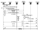
- FIG. 4 is a diagram of an exemplary Session Initiation Protocol (SIP)-to-SIP call flow, according to an embodiment of the present invention.
- the source (or originating) endpoint is the soft phone 207 d and has an identifier, bob@voiptheworld.net.
- the destination (or terminating) endpoint is the soft phone 209 c with user, alice@ipislands.com.
- the endpoint 207 d establishes communication with the STUN server 203 by issuing a binding request. This communication is established using a standard TCP handshake and authentication process (step 403 ).
- the endpoint 207 d sends a register signal, e.g., using SIP (REGISTER/200 OK), to the SIP proxy server 207 e using a connection through the TURN server 205 (step 405 ).
- the register signal message can be sent with a password that is MD5 hashed.
- the register signal is transmitted over an encrypted session (as explained above with respect to FIG. 2B ).
- the register signal message can include a “Retry-After” attribute that specifies the time period before another attempt to register is executed.
- these retries are securely exchanged over the encrypted session (e.g., session 223 of FIG. 2 ).
- the SIP proxy server 207 e responds, as in step 407 , with a 200 OK message to the endpoint 207 d.
- step 409 the endpoint 207 d submits an INVITE message to the SIP proxy server 207 e , which replies with a 100 Trying message (step 411 ).
- the proxy server 207 e determines that the URI of the destination endpoint 209 d needs to be determined. Accordingly, the SIP proxy server 207 e submits a DNS query to the ENUM server 201 , which responds with the appropriate NAPTR record (steps 413 and 415 ).
- the SIP proxy server 207 e sends the INVITE message to the SIP proxy server 209 e of the destination network (step 417 ).
- the SIP proxy server 209 e forwards the INVITE message to the destination endpoint 209 d , per step 419 .
- the endpoint 209 d then sends a 180 Ringing message, as in step 421 , to the SIP proxy server 209 e , which relays the message to the SIP proxy server 207 e (step 423 ). Thereafter, the Ringing message is transmitted, per step 425 , to the source endpoint 207 d.
- step 427 the endpoint 209 d generates a 200 OK message, forwarding the message to the SIP proxy server 209 e .
- this 200 OK message is relayed by the SIP proxy server 209 e to the other SIP proxy server 207 e .
- the 200 OK message is forwarded by the SIP proxy server 207 e to the source endpoint 207 d , as in step 431 .
- the endpoint 207 d acknowledges the SIP proxy server 207 e with an ACK message (step 431 ).
- the SIP proxy server 207 e sends the ACK message to the destination endpoint 209 d through the SIP proxy server 209 e (steps 435 and 437 ).
- the endpoints 207 d and 209 d now can exchange media via the TURN server 205 .
- FIG. 5 is a diagram of an exemplary SIP-to-PSTN (Public Switched Telephone Network) call flow, according to an embodiment of the present invention.
- SIP-to-PSTN Public Switched Telephone Network
- communication is performed via the TURN server 205 .
- the endpoint 207 d establishes communication with the STUN server 203 with a binding request, per step 501 .
- a standard TCP handshake and authentication process is executed, per step 503 , between the endpoint 207 d and the STUN server 203 .
- the endpoint 207 d transmits a register signal to the SIP proxy server 207 e (step 505 ).
- the SIP proxy server 207 e sends a 200 OK message to the endpoint 207 d in response to the Register signal, per step 507 .
- step 509 the endpoint 207 d sends an INVITE message to the SIP proxy server 207 e .
- the server 207 e then replies with a 100 Trying message (step 511 ).
- the proxy server 207 e sends a DNS query to the ENUM server 201 .
- the ENUM server 201 cannot find the corresponding URI, and indicates so to the SIP proxy server 207 e , per step 515 .
- the SIP proxy server 207 e sends an INVITE message to the media gateway 215 (step 517 ); the INVITE message specifies the telephone number.
- the media gateway 215 replies with a 180 Ringing message.
- the SIP proxy server 207 e forwards the 180 Ringing message to the endpoint 207 d , per step 521 .
- the media gateway 215 also sends a 200 OK message to the SIP proxy server 207 e .
- This message is then forwarded to the endpoint 207 d (step 525 ) by the SIP proxy server 207 e.
- the endpoint 207 d responds with an ACK message to the SIP proxy server 207 e, which sends the message to the media gateway 215 (steps 527 and 529 ).
- a call is established between the source endpoint 207 d and the PSTN via the media gateway 215 .
- FIG. 6 is a diagram of an architecture utilizing a centralized data store supporting communication among remote endpoints, according to an embodiment of the present invention.
- a communication system 600 includes a service provider network 601 deploying components to support the Interconnect services, as described above.
- the network 601 utilizes a data store 603 (or registry) to manage communication among the endpoints 605 , 607 and 609 .
- These endpoints 605 , 607 and 609 can be associated with a single enterprise, organization or entity, in which the endpoint 605 can correspond to an office location, the endpoint 607 with the home, and the endpoint 609 with a temporary, mobile location such as a hotel.
- the data store 603 stores user information as well as information on how packetized voice calls are to be routed over a public data network such as the Internet; further, this registry 603 can specify alternate paths, including circuit-switched paths, cellular paths, or media paths (e.g., IP media paths); such routing information can take many forms, including network addresses, protocol port information, etc. Additionally, the data store 603 permits the service provider to store and manage billing and rating information for calls placed by users. Further, the service provider can maintain the necessary information to authorize communication between the endpoints involving different network elements.
- the network 601 includes a SIP proxy server 611 for interfacing the various endpoints 605 , 607 and 609 .
- the SIP proxy server 611 interacts with a TURN server 613 , a STUN server 615 and an ENUM server 617 as detailed early for supporting packetized voice calls with other data networks as well as circuit-switched telephone systems.
- system 601 utilizes a gateway 619 to provide connectivity to other systems (e.g., data network or circuit switched telephone network).
- systems e.g., data network or circuit switched telephone network.
- the above architecture can be deployed in a variety of terrestrial and radio communication systems to offer the Interconnect services, which can be complementary or supplementary to other communication services.
- a wireless communication system can implement such services, as explained below.
- FIG. 7 is a diagram of a wireless communication system for providing application mobility, according to one embodiment of the present invention.
- the Interconnect services can be deployed in a wireless and wired system 700 for providing SIP-based mobile IP communication services.
- one or more multimodal mobile devices 701 can communicate using various wireless technologies—e.g., Wi-FiTM/WiMax, 802.11 or cellular.
- the multimodal device 701 can interface with either a mobile telephony (e.g., cellular) network 703 or a wireless data network 705 .
- Each of these networks 703 and 705 communicates with a public data network 707 , such as the Internet.
- a service provider network 709 also has connectivity to the Internet 707 , which communicates with a Public Switched Telephone Network (PSTN) 711 .
- PSTN Public Switched Telephone Network
- IP side controls all fixed and mobile services. Also, it is assumed that calls are established over a myriad of networks: the Internet 707 , 2G/3G mobile networks (3GPP and 3GPP2) 703 , Time Division Multiplexing (TDM) networks 714 , such as the PSTN and PBXs and ISDN (Integrated Digital Services Network), 4G (4 th Generation) Wi-FiTM and WiMax wireless networks, and IP PBXs and other IP systems, such as H.323.
- networks such as the PSTN and PBXs and ISDN (Integrated Digital Services Network)
- 4G (4 th Generation) Wi-FiTM and WiMax wireless networks such as H.323.
- Communication services are enabled or deployed on the IP side and can be based, for instance, on SIP and its associated application layer protocols, such as developed in the SIMPLE, SIPPING, IPTEL, XCON and ENUM working groups of the Internet Engineering Task Force (IETF).
- the system 700 includes SIP telephony and IM devices that are endpoints on the Internet 707 . Gateways to 2G/3G mobile phone networks are also endpoints on the Internet 707 . Further, SIP-PSTN and SIP-PBX are endpoints on the Internet 707 .
- the wireless network 705 (which is a “Visited” network with respect to the service provider network 709 ) includes an access point 713 (e.g., Ethernet switch) as well as an AAA server 715 .
- the service provider network 709 includes an AAA server 717 .
- the network 709 provides a STUN/TURN server 719 ; these two functions can also be implemented as separate components, as evident from the previous discussion of STUN and TURN functionalities.
- the service provider network 709 includes a SIP proxy server 721 .
- the mobile telephony network (e.g., cellular network) 703 includes a mobile switch 723 for processing communication sessions from the multimodal mobile station 701 to the PSTN 711 or the Internet 707 through a mobile gateway 725 .
- a gateway 727 is employed to connect from the PSTN 711 to the Internet 707 ; in this manner, the station 729 within the PSTN 711 can be reached by calls placed over the Internet 707 .
- rich services such as presence, events, instant messaging, voice telephony, video, games and entertainment services can be supported by the service provider network 709 .
- IM Instant Messaging
- SMS mobile Short Messaging Systems
- seamless communications (using presence, SIP events, text, voice, video communications and file sharing) is enabled in conjunction with a single identity or a suite of similar identifiers. That is, the multimodal device 701 enables a user to have a single identity and a single service subscription on all mobile and fixed networks, whereby the device 701 can operate in dual modes to communicate using any wireless or wired network.
- One single identity can take the form of a phone number and/or a URI (same or similar to the e-mail address) for all fixed and mobile networks and for all types of communications.
- the phone number and/or URI can be the only entry in the address book, by which the called party can be both reached and identified.
- a single identity is provided for the caller for access to all wired and wireless networks. Also, a single subscription can be utilized for all types of networks and devices. Further, NAT and firewall traversal is transparent to the user. Secure communications can be achieved based on network asserted user identity and encryption on demand.
- the mobile device 701 can interwork with PBXs (not shown) or can provide PBX-like services. Calls and conferences can be maintained while switching between the wireless networks 705 (e.g., 2G/3G (2 nd Generation/3 rd Generation) mobile phone networks 703 , Wi-FiTM/WiMax wireless broadband) and a wired PSTN 711 (or PBX network).
- PBXs not shown
- the wireless networks 705 e.g., 2G/3G (2 nd Generation/3 rd Generation) mobile phone networks 703 , Wi-FiTM/WiMax wireless broadband
- a wired PSTN 711 or PBX network
- the Presence, Events, and IM Gateway 319 provides gateway services from SIP to and from other protocols to enable seamless and interoperable presence, events, and instant messaging (IM).
- Presence, events and instant messaging (IM) have evolved as core new communication services on the Internet and in private IP networks with hundreds of million users worldwide.
- Leading edge mobile phone services, such as push-to-talk are based on presence, events and IM. It is no coincidence that telephony has become an adjunct to popular IM services, where making a phone call is just another option to choose from various other communication modes.
- IP-IP voice calls are also enabled, without the use of telephone network or dependency on phone numbers.
- GUIs Graphical User Interfaces
- IM infrastructure is completely separate from other forms of communications, such as voice, video, conferencing, etc.
- IM services are proprietary and require gateways for at least some degree of basic communications between disparate systems.
- SIP IM Protocols Leveraging Extensions SIMPLE
- 3G IMS Third Generation IP Multimedia Service
- Gateways between legacy IM protocols can be provided as a fully meshed architecture, where the number of gateways increases by the square of the number of protocols.
- migration to a common IM core based on SIMPLE standards is a more effective approach and provides gateways between legacy IM systems and SIMPLE. Under such a scenario, the increase in gateways is only linear with the number of IM protocols utilized.
- the IM architecture is based on the SIMPLE standards.
- the presence event package describes the usage of the Session Initiation Protocol (SIP) for subscriptions and notifications of presence. Presence is defined as the willingness and ability of a user to communicate with other users on the network.
- the presence event package and associated notifications are more detailed, respectively in “A Presence Event Package for the Session Initiation Protocol (SIP)” by J. Rosenberg, Internet Draft, IETF work in progress, January 2003; and “Functional Description of Event Notification Filtering” by H. Khartabil et al., Internet Draft, IETF work in progress, August 2004 (both of which are incorporated herein by reference in their entireties).
- Presence has been limited to “on-line” and “off-line” indicators; the notion of presence here is broader.
- Subscriptions and notifications of presence are supported by defining an event package within the general SIP event notification framework.
- the filtering of event notifications refers to the operations a subscriber performs in order to define filtering rules associated with event notification information.
- the handling of responses to subscriptions carrying filtering rules and the handling of notifications with filtering rules applied to them is defined.
- the definition also describes how the notifier behaves when receiving such filtering rules and how a notification is constructed.
- the watcher information date format defines template-package for the SIP event framework.
- Watcher information refers to the set of users subscribed to a particular resource within a particular event package. Watcher information changes dynamically as users subscribe, unsubscribe, are approved, or are rejected. A user can subscribe to this information, and therefore learn about changes to it.
- This event package is a template-package because it can be applied to any event package, including itself. Watcher functions are further detailed in “A Watcher Information Event Template-Package for SIP” by J. Rosenberg, Internet Draft, IETF work in progress, January 2003 (which is incorporated herein by reference in its entirety).
- the Presence Information Data Format defines a basic format for representing presence information for a presentity.
- a presentity is an entity whose presence is tracked; the presentity can project its presence information, for example, by registering status information, location information (or other attributes) with a presence server (not shown).
- That format defines a textual note, an indication of availability (open or closed) and a URI for communication.
- it is frequently useful to convey additional information about a user that needs to be interpreted by an automaton, and is therefore not appropriate for placement in the note element of the PIDF document.
- the extensions have been chosen to provide features common in existing presence systems at the time of writing, in addition to elements that could readily be derived automatically from existing sources of presence, such as calendaring systems, or sources describing the user's current physical environment.
- the Presence Information Data Format can utilize an XML format.
- the Extensible Markup Language (XML) Configuration Access Protocol (XCAP) allows a client to read, write and modify application configuration data, stored in XML format on a server.
- XCAP maps XML document sub-trees and element attributes to HTTP URIs, so that these components can be directly accessed by HTTP. Additional details of XCAP is provided in “The Extensible Markup Language (XML) Configuration Access Protocol (XCAP)” by J. Rosenberg, Internet Draft, IETF work in progress, July 2004 (which is incorporated herein by reference in its entirety).
- XML Configuration Access Protocol allows a client to read, write and modify application configuration data, stored in XML format on a server. The data has no expiration time, so it must be explicitly inserted and deleted. The protocol allows multiple clients to manipulate the data, provided that they are authorized to do so.
- XCAP is used in SIMPLE based presence systems for manipulation of presence lists and presence authorization policies. Thus, XCAP is rather suitable for providing device independent presence document manipulation.
- a series of related textual messages between two or more parties can be viewed as part of a session with a definite start and end. This is in contrast to individual messages each sent completely independently.
- messaging schemes only track individual messages as “page-mode” messages, whereas messaging that is part of a “session” with a definite start and end is called “session-mode” messaging.
- Page-mode messaging is enabled in SIMPLE via the SIP MESSAGE method. Session-mode messaging has a number of benefits over page-mode messaging however, such as explicit rendezvous, tighter integration with other media types, direct client-to-client operation, and brokered privacy and security.
- the Contact Information for Presence Information Data Format is an extension that adds elements to PIDF that provide additional contact information about a presentity and its contacts, including references to address book entries and icons.
- CIPID is further detailed in “CIPID: Contact Information in Presence Information Data Format” by H. Schulzrinne, Internet Draft, IETF work in progress, July 2004 (which is incorporated herein by reference in its entirety).
- Presence information e.g., represented as Presence Information Data Format (PIDF) and Rich Presence Information Data Format (RPID) describes the current state of the presentity. RPID also allows a presentity to indicate how long certain aspects of the status have been valid and how long they are expected to be valid, but the time range has to include the time when the presence information is published and delivered to the watcher. This restriction is necessary to avoid backwards-compatibility problems with plain PIDF implementations. RPID is additionally described in “RPID: Rich Presence Extensions to the Presence Information Data Format” by H. Schulzrinne et al., Internet Draft, IETF work in progress, March 2004 (which is incorporated herein by reference in its entirety).
- PIDF is further detailed in “Timed Presence Extensions to the Presence Information Data Format (PIDF) to Indicate Presence Information for Past and Future Time Intervals” by H. Schulzrinne, Internet Draft, IETF work in progress, July 2004 (which is incorporated herein by reference in its entirety).
- the watcher can better plan communications if it knows about the presentity future plans. For example, if a watcher knows that the presentity is about to travel, it might place a phone call earlier.
- past information may be the only known presence information.
- Such past information may provide watchers with an indication of the current status. For example, indicating that the presentity was at a meeting that ended an hour ago indicates that the presentity is likely in transit at the current time.
- FIG. 8 shows exemplary multimodal wireless and wired devices that can access a variety of disparate networks using pertinent communication stacks and physical network ports to those networks.
- multimodal communication devices 801 a - 801 d can have mobile phone capabilities as well as computing functions (e.g., Personal Digital Assistant (PDA)). These exemplary devices 801 a - 801 d can provide PC-phone/PDA applications, PDA synchronization, “dial” from the PC, etc.
- the device 801 c for instance, can include a Wi-FiTM terminal for use in the office or home network, and can also be a desktop speakerphone having a suitable desktop socket.
- some of the functions described can be accomplished using a Bluetooth link between the multimodal communication device (e.g., 801 a - 801 c ) and the PC/laptop or with a Bluetooth enabled SIP phone that is connected to the Internet 813 —notably for such functions as ICE and STUN/TURN servers for NAT and firewall traversal.
- the following process describes network and service access to Internet based SIP services by the multimodal devices 801 a - 801 d .
- an IP address is obtained, for example, using Dynamic Host Configuration Protocol (DHCP).
- DHCP Dynamic Host Configuration Protocol
- ICE provides determination of the optimum NAT/firewall traversal.
- the device 801 a can then register with the home SIP registrar to receive the SIP based IP communication services.
- a SIP re-INVITE is utilized to switch between networks without leaving an established session, such as a conference.
- Smooth handoff in wireless networks can be readily accomplished at the Network Layer 2, in the respective radio networks, such as in 2G/3G or Wi-FiTM/WiMax networks.
- the user may be prompted by the mobile device 801 a to approve the switch from one network type to another, such as when switching from the mobile 2G network 809 to an enterprise or hot spot Wi-FiTM network (not shown).
- the system can utilize a single SIP registrar (e.g., the home registrar).
- the multimodal mobile device 801 (of FIG. 8A ) includes a cellular transceiver 851 for communication with cellular systems.
- a wireless transceiver 853 is also included for connecting to wireless networks (e.g., 802.11, etc.).
- a network interface card (NIC) 855 is provided for connectivity to a wired network; the NIC 855 can be an Ethernet-type card.
- Use of the transceivers 853 , 855 or NIC 855 depends on the mode of operation of the device 801 , and is controlled by a controller 857 . Radio transmissions can be relayed via the antenna 861 .
- the multimodal mobile device 801 additionally includes a processor 863 for executing instructions associated with the various applications (e.g., PDA functions and applications, etc.), as well as memory 865 (both volatile and non-volatile) for storing the instructions and any necessary data.
- a processor 863 for executing instructions associated with the various applications (e.g., PDA functions and applications, etc.), as well as memory 865 (both volatile and non-volatile) for storing the instructions and any necessary data.
- FIGS. 9-15 are diagrams of various call flows involving the multimodal devices. For the purposes of explanation, these processes are described with respect to the system 700 of FIG. 7 .
- FIG. 9 is a diagram of a process for authentication and registration of a multimodal device in a data network, according to one embodiment of the present invention.
- the mobile station 801 connects to the Access Point 713 (which in this example is an 802.1 access point/Ethernet switch) using an Extensible Authentication Protocol (EAP).
- EAP Extensible Authentication Protocol
- the Access Point 713 then communicates using EAP over RADIUS, as in step 903 , with the AAA server 715 .
- This server 715 is considered a “visited” RADIUS AAA server 715 .
- the AAA server 715 then issues a Request message for authentication to the AAA server 717 of the service provider network 709 (step 905 ).
- the AAA server 717 responds with an Answer message, per step 907 .
- the Visited AAA server 715 returns a Response message to the Access Point 713 , which signals an EAP Success to the mobile station 701 , per steps 909 and 911 .
- step 913 the mobile station 701 and the Access Point 713 perform a Dynamic Host Configuration Protocol (DHCP) process.
- DHCP Dynamic Host Configuration Protocol
- the mobile station 701 establishes communication with the STUN/TURN server 719 , as in step 915 .
- communication with the SIP server 721 is executed by the mobile station 701 through a REGISTER and 200 OK exchange, per steps 917 and 919 .
- FIG. 10 is a diagram of a process for establishing a call from a multimodal device to the PSTN, according to one embodiment of the present invention.
- this call flow is performed in cellular (e.g., 2G) mode, whereby the mobile station 701 performs a call attempt specifying the dialed digits to the cellular mobile switch 723 (step 1001 ).
- the cellular mobile switch 723 signals a call setup request (ISUP Initial Address Message (IAM) or Setup with dialed digits) to the mobile gateway 725 .
- IAM ISUP Initial Address Message
- the gateway 725 then generates an INVITE message to the SIP proxy server 721 , per step 1005 .
- the server 721 conveys the INVITE to the PSTN gateway 727 , which responds with a 200 OK message (steps 1007 and 1009 ).
- the SIP proxy server 721 forwards, as in step 1011 , to the mobile gateway 725 .
- This gateway 725 consequently sends, per step 1013 , an Answer Message (ANM) or Connect message to the cellular mobile switch 723 .
- NAM Answer Message
- the switch 723 signals a Connected message to the mobile station 701 .
- the above call flow involves a call being initiated by the mobile station 701 ; the following process describes a call being received by the mobile station 701 from a station within the PSTN 711 .
- FIG. 11 is a diagram of a process for establishing a call to a multimodal device from the PSTN, according to one embodiment of the present invention.
- a station within the PSTN 711 places a call to the mobile station 701 .
- the PSTN gateway 727 sends an INVITE message, per step 1101 , to the SIP proxy server 721 , which forwards the INVITE message to the mobile gateway 725 (step 1103 ).
- the mobile gateway 725 sends an IAM or Setup message to the cellular mobile switch 723 .
- the switch 723 then signals an Alerting message to the mobile station 701 , per step 1107 .
- the mobile station 701 responds with an Answer to the cellular mobile switch 723 .
- the switch 723 next relays an ANM or Connect message, as in step 1111 , to the mobile gateway 725 .
- the mobile gateway 725 transmits a 200 OK message to the SIP proxy server 721 (step 1113 ).
- This server 721 subsequently forwards the 200 OK message to the PSTN gateway 727 , per step 1115 .
- the PSTN gateway 727 replies with an ACK message to the SIP proxy server 721 , which relays this message to the mobile station 725 (step 1119 ). Thereafter, a call is established between the mobile station 701 and the originating station, as in step 1121 .
- the PSTN gateway 727 signals the termination of the 2G call with a BYE message to the SIP proxy server 721 , per step 1219 .
- the proxy server 721 forwards the BYE message to the mobile gateway 725 , as in step 1221 .
- the mobile gateway 725 sends a Release message to the cellular mobile switch 723 , which sends a Disconnect message to the mobile station 701 .
- the mobile station 701 can switch from an IP call to a 2G call, as next explained.
- FIG. 13 is a diagram of a process for IP-to-cellular mode switching during a call supported by the PSTN, according to one embodiment of the present invention.
- the mobile station 701 has established a packetized voice call (e.g., operating in IP mode) with a station within the PSTN 727 .
- the mobile station 701 sends a call attempt request, which indicates the dialed digits to the cellular mobile switch 723 (step 1303 ).
- the cellular mobile switch 723 sends a call setup request, IAM or Setup with dialed digits, to the mobile gateway 725 , per step 1305 .
- the mobile gateway 725 generates an INVITE message to the SIP proxy server 721 , per step 1307 .
- the server 721 sends the INVITE to the PSTN gateway 727 (step 1309 ), which responds with a 200 OK message (step 1311 ).
- the proxy server 721 sends the 200 OK message to the mobile gateway 725 , as in step 1313 .
- the mobile gateway 725 sends an ANM (Answer Message) or Connect message to the cellular mobile switch 723 .
- the switch 723 signals a Connected message to the mobile station 701 , per step 1317 .
- the mobile gateway 725 sends an ACK message, per step 1319 , to the SIP proxy server 721 , which transmits the ACK message to the PSTN gateway 727 (step 1321 ). Thereafter, the PSTN gateway 727 sends a BYE message to the SIP proxy server 721 , which forwards the message to the mobile station 701 (steps 1323 and 1325 ). In step 1327 , the mobile station 701 transmits a 200 OK message to the SIP proxy server 721 ; the 200 OK message is further sent to the PSTN gateway 727 (step 1329 ). Consequently, a TDM call is now supported between the mobile station 701 and the PSTN station.
- step 1407 the SIP proxy server 721 to the mobile gateway 725 , which transmits an ISUP (ISDN User Part) Initial Address Message (IAM) or Setup message to the cellular mobile switch 723 (step 1409 ).
- the cellular mobile switch 723 exchanges Alerting/Answer signaling with mobile station B, per step 1411 .
- the cellular mobile switch 723 sends an ANM or Connect message to the mobile gateway 725 (step 1413 ).
- the mobile gateway 725 generates, as in step 1415 , a 200 OK message to the SIP proxy server 721 .
- the proxy server 721 responds back with a 200 OK message, per step 1417 .
- step 1419 the mobile gateway 725 sends an ANM or Connect message to cellular mobile switch 723 .
- a connection is established with the mobile station A (step 1421 ).
- the mobile gateway 725 sends an ACK message to the SIP proxy server 721 , which transmits its own ACK message to the mobile gateway 725 (step 1425 ).
- the cellular mobile switch 723 has established cellular communication with both the mobile stations A and B, per steps 1427 and 1429 .
- FIG. 15 is a diagram of a process for cellular-to-IP mode switching mid-call, according to one embodiment of the present invention.
- This scenario involves a cellular call being in progress between the mobile station A and the mobile station B, as in steps 1501 and 1503 .
- the mobile station A performs an 802.1 authentication with the Access Point 723 .
- the mobile station A performs SIP registration with the STUN/TURN functions via the SIP proxy server 721 (step 1507 ).
- the mobile station A sends an INVITE message to the SIP proxy server 721 .
- the SIP proxy server 721 then sends an INVITE message to the mobile gateway 725 , per step 1511 .
- the mobile gateway 721 generates a 200 OK message to the SIP proxy server 721 , which sends the 200 OK message to the mobile station A (steps 1513 and 1515 ).
- step 1517 the mobile station A forwards an ACK message to the SIP proxy server 721 in response to the 200 OK message.
- the SIP proxy server 721 per step 1519 , sends an ACK to the mobile gateway 725 .
- the mobile gateway 725 next sends a BYE message to the SIP proxy server 721 (step 1521 ).
- the mobile gateway 725 next sends a Release message to the cellular mobile switch 723 , which in turn issues a Disconnect message to the mobile station A (steps 1523 and 1525 ).
- the SIP proxy server 721 transmits a BYE message to the mobile gateway 725 , which responds with a 200 OK message (steps 1527 and 1529 ).
- the mobile station B still engaged in a cellular call leg, per step 1531 .
- the SIP proxy server 721 sends a 200 OK to the mobile gateway 725 .
- the mobile station A communicating over IP media, as in step 1535 .
- FIG. 16 is a diagram of an Operational Support System (OSS) architecture, according to one embodiment of the present invention.
- the architecture 1600 leverages service-oriented architecture principles and associated technologies. For example, remotely callable services, implemented using Web Services standards, are used to encapsulate access to databases; encapsulate access to existing or “legacy” systems (as necessary). These services advantageously provide OSS function implementations that are modular. Additionally, the callable services provide interfaces for other systems to send notifications to IP-IC components and to request information. These services further advantageously provide a clean, platform-agnostic, standards-based decoupling between web-facing and back-end systems.
- OSS Operational Support System
- the architecture 1600 includes three primary tiers: an Access Tier 1601 , a Services Tier 1603 , and a Resource Tier 1605 .
- the Access Tier 1601 (which can also be referred to as a “Presentation Tier”) permits user and system access into the OSS for customers and service provider's sales/support.
- the Services Tier 1603 is the focal point of the OSS architecture 1600 , where a majority of the functionalities reside.
- the Resource Tier 1605 encompasses the elements that the services act upon.
- the OSS architecture 1600 manages these various resources.
- the subsystems of the Access Tier 1601 include a Web Portal 1607 , a Web Services Gateway 1609 , and an Identity Management and Access Control component (not shown). These interrelated components allow human users (e.g., customer employees or service provider's staff) and customer systems 1611 to access the OSS services via, for example, web browser 1611 or via Simple Object Access Protocol (SOAP) invocations.
- SOAP Simple Object Access Protocol
- the external access architecture are as follows.
- a web server is provided in a DMZ.
- programming and runtime environment is supported for dynamic generation of HTML pages and for handling incoming web requests.
- An XML firewall is deployed for screening and routing inbound SOAP traffic coming into DMZ from customers.
- web server agents are plugged into the web server and XML firewall.
- a Policy Server and LDAP backing store can be utilized.
- the identity administration allows authorized users to be added, and to permit these users to enter orders, update information, provision users, etc., on behalf of their organization or company.
- This administration function enable delegation of administration privileges to customer administrators, allowing them to add further users and grant them access privileges. It is assumed the service provider has some control in identity administration, as the customer cannot be completely self-managed using, e.g., web self-service. It is important to note that this identity administration function is distinct from end-user identity management within the core SIP telephony components.
- the identity administration is concerned with administrative accounts that allow customer employees to interact with the OSS systems online to allow customer self-service.
- the Services Tier 1603 includes services that are mainly concerned with encapsulating resources, such as data and other managed resources, through Resource Encapsulation Services 1615 .
- the Services Tier 1603 also includes application process activities 1617 —behavior, or actually doing something.
- the arrows directed into the Services Tier 1603 constitute event sources that trigger activities within the services.
- Exemplary triggering events involve activities undertaken by the customer via web browser, notifications coming in from legacy systems (e.g., Accounts Receivable informing that a given customer has paid its bill), and management-related notifications originating from IP Services components in the architecture.
- legacy systems e.g., Accounts Receivable informing that a given customer has paid its bill
- management-related notifications originating from IP Services components in the architecture e.g., a media relay server (or its management agent) can inform the OSS services that a resource consumption metric has gone above a high-water mark 1619 and additional capacity needs to be provisioned.
- some OSS activities are triggered by time-based events, as suggested by the hour glass. In particular, activities related to the monthly billing cycle are schedule driven.
- the Resource Tier 1605 includes databases 1621 and legacy systems 1623 , as well as primary IP Services components 1625 (which are at the core of the IP-IC offering).
- FIG. 17 is a diagram of a financial system for supporting the IP interconnect service, according to one embodiment of the present invention.
- the system 1700 permits the IP-IC components to largely perform their own billing computation and presentment and to integrate with existing financial systems 1701 (e.g., Accounts Receivable (AR) or other Finance systems).
- existing financial systems 1701 e.g., Accounts Receivable (AR) or other Finance systems.
- the system 1700 assume the integration is a responsibility of these existing (or “legacy”) financial systems 1701 .
- the system 1700 provides for encapsulating this integration point with a Web Service—this is transparent to the other components specific to the IP-IC OSS. For example, a clean SOAP interface to those existing systems is used, even if that interface hides the legacy complexity of document file transfer using proprietary data formats.
- FIG. 17 shows, User Provisioning is invoked by the Access Tier 1601 , driven by customer self-service events.
- the Access Tier 1601 then pushes updates to the Customer Profile service and the ENUM/DNS servers.
- the system 1700 employs a GUI 1703 , which provides one or more Customer Self-Service screens to permit the user to provision and manage their services.
- a Billing Presentment component 1705 is also provided.
- presentment can be performed electronically via the web portal 1607 .
- the Billing Presentment component 1705 can be though of as presentation code in the Web Portal 1607 , which draws the underlying statement information for each given customer from the Billing Statement store 1707 , and renders that into, for example, HTML markup for presentation to the user.
- the User Provisioning component 1709 is a Web Service which provides interfaces for a single user, or a set of multiple users (possibly thousands), to be added to the system 1700 .
- the end-result of user provisioning for instance, is that ENUM mappings for the user(s), telephone number to SIP URI, are added to the ENUM DNS server or servers 1710 .
- customer profile information is adjusted to increment or decrement the current user count field for the customer or customers.
- mirror databases are updated with the ENUM mapping information. This information can be captured in database format (in addition to DNS) for other uses, e.g., to support white pages directory.
- the Application Programming Interface can include methods for adding a single user to the system, dropping a single user from the system, bulk-loading an array of users to the system, and for performing bulk drops.
- API Application Programming Interface
- These API functions can be exposed to the customers as XML Web Services interfaces, which the customer systems 1613 can programmatically call.
- the customer self-service screens of the IP-IC Web Portal can also provide Graphical User Interface (GUI) interfaces allowing customer administrative personnel to add and drop users.
- GUI Graphical User Interface
- the User Provisioning component 1709 performs dynamic updates to the DNS server or servers.
- the dynamic update can be executed by using public domain JavaTM APIs into DNS, using available C language library and use JNI to support binding of JavaTM code to object code, or exercise available DNS management interfaces.
- one of the roles of the User Provisioning service is to hide the exact details of this DNS binding from upstream systems, so all these upstream systems “see” a simple Web Service interface.
- the Customer Profile service 1711 updates bookkeeping on the user count. This can include updating a current user count field and updating a monthly peak user count field with respect to the User Provisioning component 1709 .
- the Customer Profile component 1711 also interacts with a Billing Computation component 1713 and a Fulfillment (also referred to as an Order Management/Customer Provisioning) component 1715 .
- provisioning can occur, in an exemplary embodiment, at two different levels: (1) provisioning and de-provisioning of individual SIP end-users (an ongoing activity), and (2) provisioning of customers.
- provisioning and de-provisioning of individual SIP end-users an ongoing activity
- provisioning of customers In contrast with up-front activities of provisioning a new customer, configuring a given customer facility or PBX to point to IP-IC DNS, redirect, relay and/or signaling conversion servers, etc.
- the User Provisioning service 1709 described in this example focuses on the former notion of provisioning the SIP end-user, not customer-level provisioning.
- the Fulfillment component 1715 focuses on the customer-level sense of provisioning.
- the Billing Computation component (or engine) 1713 is a service that is primarily process-oriented. It is triggered by a scheduler 1717 —e.g., on a monthly billing cycle. Depending upon the service pricing model, the Billing Computation component 1713 can also be triggered on a daily basis in order to take a daily sample of each Customer's user count. The samples can then be used to update a running accumulator for the purpose of calculating a monthly average user count, for instance.
- this function can be integrated into the billing computation, with regard to applying relevant discounts.
- the pricing model is based upon peak user count over the course of the month, rather than the average.
- the peak user count is maintained by the Customer Profile component 1711 , each time it gets an increment/decrement user count event from the User Provisioning Service 1709 .
- the Billing Computation engine 1713 cycles through the customers.
- the Customer Profile 1711 is queried for the monthly peak user count for each customer.
- Each customer's Service Profile record 1721 is also consulted to determine the optional services that the customer is subscribed to.
- the system 1700 allows for a business model where different features are optional, such as signal conversion or media relay, and such options incur additional charges above the base offering price.
- the Billing Computation engine 1713 pulls (and caches) the current base price figures, for each option, from a Product Description store 1723 . With all of this information, the Billing Computation engine 1713 can then calculate the customer's itemized charges and bottom line. The Billing Computation engine can then consult the Rating component 1719 to determine discount adjustments for the customer. Further, the Billing Computation engine 1713 prepares, for example, a XML document that represents the complete monthly information regarding what the customer bought and owes, and posts these XML documents to the Billing Statement store 1707 . The Billing Statement 1707 store provides storage of these documents persistently for later consumption by the Billing Presentment component 1705 and financial systems 1701 .
- the Billing Statement component 1707 is a data-oriented service, and supports persistent storage of the billing statement documents that are created by the Billing Computation engine 1713 for each customer (e.g., each month). Specifically, the Billing Statement component 1707 maintains storage for both the current billing cycle and for archival storage of all past billing statements.
- each record in the Billing Statement tables stores an ASCII document.
- This document can be in XML format document for detailing the itemized charges for a given customer, applied discounts and bottom line.
- the XML document records the detail of what the customer bought, and what the customer owe.
- These XML documents stored in the Billing Statement component 1707 represent all the information that is required for Billing Presentment 1705 to present an e-invoice to the customer, and for the financial systems 1701 to collect payment and report back on the status of customer payment or delinquency.
- the Product Description component 1723 stores product information received from the Product Design/Maintenance component 1725 .
- the Product Description component 1723 is mainly a data store, and records information about the product offering as a whole, plus separate information about each of the product's available options. This arrangement externalizes general information about the product so as to avoid hard-coding such information within program code.
- pricing information which is likely subject to change, and best to keep in an external store. If a pricing model is adopted where separate product options are priced individually, then each option could have an associated base price (or price rate per user).
- the main client of the Product Description service 1723 is the Billing Computation engine 1713 , which mainly needs to extract the base pricing information in order to compute bills.
- the Service Profile component 1721 is another data-oriented component, and is fed by the Fulfillment component 1715 (which can be GUI driven by Order Entry, Product Design and Customer Support web screens).
- the Service Profile component 1721 can be queried on a monthly cycle by the Billing Computation component 1713 in the course of calculating each customer's bill.
- the Service Profile component 1721 persists the complete product description, for each customer, of the products provisioned by the customer. If the product offering has several optional features (such as signal conversion, media relay, etc.), then the Service Profile information for each customer details the options elected by the customer, along with attributes that parameterize variable quantities associated with the different product options.
- the Service Profile component 1721 thus represents the instantiation of the IP-IC product offering for each customer. This is in contrast with the Product Description component 1723 , which embodies a description of the product as a whole, not any given customer's realization of the product. (In object-oriented parlance, the Product Description would be thought of as “class-level,” and the Service Profile would be “instance-level.”)
- the Fulfillment component 1715 provides a back-end to the customer self-service web screens, as well as sales/support screens related to order management and customer provisioning processes.
- provisioning involves multiple levels—provisioning in the sense of enabling SIP end-users to use the system; and provisioning in the sense of “turning up” a new Customer and maintaining/updating their information at a customer-level.
- the Fulfillment component 1715 supports the customer-level sense of provisioning, not the SIP user management, which is handled by the User Provisioning component.
- the Fulfillment component 1715 supports establishing new customer accounts, and creating an IP-IC product specific Accounts for an existing customer.
- the Fulfillment component 1715 can coordinate with customer data stores of record to ensure that proper corporate Customer ID is used.
- the Fulfillment component 1715 also provides support for a customer entering survey of their needs and environment, which can assist sales personnel in product design/configuration.
- This Fulfillment component 1715 additionally provides Customer Premise Equipment (CPE) information entry, and can inform customers of the proper URLs or other binding information that they need for operational use of the various servers (e.g., DNS, ENUM Redirect, STUN, TURN, Signal Conversion gateways, etc.).
- CPE Customer Premise Equipment
- the Fulfillment component 1715 permits customer election of product options that define what the customer is buying. For example, the component can determine whether the customer require signal conversion, media relay, etc. Further, the Fulfillment component 1715 supports entering site information.
- the Fulfillment component 1715 communicates with an Inventory component 1727 .
- this Inventory component 1727 is a data component that tracks relevant resource inventory, both at the customer premises via the “legacy” customer data store 1729 and resources that are internal to the service provider. It is noted that separate stores for these two sorts of inventory information can be maintained.
- the inventory store can be kept in a relational database.
- internal resources that might be considered for storage in some sort of inventory service include CPUs (and their associated IP addresses), databases, deployed services that comprise the OSS architecture.
- the inventory of deployed services can be deployed as a service directory, such as UDDI, rather than within a relational database.
- UDDI is a web-based distributed directory that enables businesses to list themselves on the Internet.
- FIG. 18 is a diagram of a service assurance infrastructure components capable of supporting the Interconnect services, in accordance with an embodiment of the present invention.
- the service assurance infrastructure 1800 can be thought of as a management plane (and somewhat orthogonal to the other functional components discussed previously).
- Service assurance is a broad category of functions and systems encompassing components and processes related to keeping the core systems and support systems operational. Assurance functions can include monitoring, reporting, alarm management, capacity management and planning, autonomic (self-healing) recovery techniques, Service Level Agreement (SLA) management, policy-driven resource allocation, etc.
- SLA Service Level Agreement
- the core of the service assurance architecture is based on a Manager/Agent model.
- a number of different Agent types and instances (“active agents”) 1801 are responsible for monitoring the vital signs of various resources 1803 (services, CPUs, databases) that make up the system environment. These active agents provide information to a Management Layer 1805 , which can be single tiered or multi-tiered.
- the Management Layer 1805 provides information to other interested systems, such as a management console 1807 , capacity management component 1809 , alerts 1811 , and a report engine 1813 , etc.
- the Management Console 1807 can be a rich client.
- a rich client can be implemented with JavaTM applets, JavaTM WebStart deployment of a JavaTM application, or a .NET Smart Client, deployed perhaps with technology such as Microsoft ClickOnce technology (or via a hyper-link that resolves to an .exe, similar in spirit to the JavaTM applet model).
- the management infrastructure of the service assurance systems determines when and where additional CPU resource are needed; alerts could be raised, and physical capacity could be provisioned (i.e., another CPU rack installed).
- the Agent tier 1801 can be involved not only with monitoring health of deployed systems, but also with dynamic deployment of services into the environment—service life-cycle management.
- the growth of the core servers (e.g., Media Relay instances) supporting the Interconnect services can be readily management using the arrangement of FIG. 18 .
- the Media Relay instances can be deployed on-demand onto a grid-like farm of resources.
- the processes described herein for supporting Interconnect services may be implemented via software, hardware (e.g., general processor, Digital Signal Processing (DSP) chip, an Application Specific Integrated Circuit (ASIC), Field Programmable Gate Arrays (FPGAs), etc.), firmware or a combination thereof.
- DSP Digital Signal Processing
- ASIC Application Specific Integrated Circuit
- FPGA Field Programmable Gate Arrays
- FIG. 19 illustrates a computer system 1900 upon which an embodiment according to the present invention can be implemented.
- the computer system 1900 includes a bus 1901 or other communication mechanism for communicating information and a processor 1903 coupled to the bus 1901 for processing information.
- the computer system 1900 also includes main memory 1905 , such as a random access memory (RAM) or other dynamic storage device, coupled to the bus 1901 for storing information and instructions to be executed by the processor 1903 .
- Main memory 1905 can also be used for storing temporary variables or other intermediate information during execution of instructions by the processor 1903 .
- the computer system 1900 may further include a read only memory (ROM) 1907 or other static storage device coupled to the bus 1901 for storing static information and instructions for the processor 1903 .
- a storage device 1909 such as a magnetic disk or optical disk, is coupled to the bus 1901 for persistently storing information and instructions.
- the computer system 1900 may be coupled via the bus 1901 to a display 1911 , such as a cathode ray tube (CRT), liquid crystal display, active matrix display, or plasma display, for displaying information to a computer user.
- a display 1911 such as a cathode ray tube (CRT), liquid crystal display, active matrix display, or plasma display
- An input device 1913 is coupled to the bus 1901 for communicating information and command selections to the processor 1903 .
- a cursor control 1915 is Another type of user input device, such as a mouse, a trackball, or cursor direction keys, for communicating direction information and command selections to the processor 1903 and for controlling cursor movement on the display 1911 .
- the processes described herein are performed by the computer system 1900 , in response to the processor 1903 executing an arrangement of instructions contained in main memory 1905 .
- Such instructions can be read into main memory 1905 from another computer-readable medium, such as the storage device 1909 .
- Execution of the arrangement of instructions contained in main memory 1905 causes the processor 1903 to perform the process steps described herein.
- processors in a multi-processing arrangement may also be employed to execute the instructions contained in main memory 1905 .
- hard-wired circuitry may be used in place of or in combination with software instructions to implement the embodiment of the present invention.
- embodiments of the present invention are not limited to any specific combination of hardware circuitry and software.
- the computer system 1900 also includes a communication interface 1917 coupled to bus 1901 .
- the communication interface 1917 provides a two-way data communication coupling to a network link 1919 connected to a local network 1921 .
- the communication interface 1917 may be a digital subscriber line (DSL) card or modem, an integrated services digital network (ISDN) card, a cable modem, a telephone modem, or any other communication interface to provide a data communication connection to a corresponding type of communication line.
- communication interface 1917 may be a local area network (LAN) card (e.g. for EthernetTM or an Asynchronous Transfer Model (ATM) network) to provide a data communication connection to a compatible LAN.
- LAN local area network
- Wireless links can also be implemented.
- communication interface 1917 sends and receives electrical, electromagnetic, or optical signals that carry digital data streams representing various types of information.
- the communication interface 1917 can include peripheral interface devices, such as a Universal Serial Bus (USB) interface, a PCMCIA (Personal Computer Memory Card International Association) interface, etc.
- USB Universal Serial Bus
- PCMCIA Personal Computer Memory Card International Association
- the network link 1919 typically provides data communication through one or more networks to other data devices.
- the network link 1919 may provide a connection through local network 1921 to a host computer 1923 , which has connectivity to a network 1925 (e.g. a wide area network (WAN) or the global packet data communication network now commonly referred to as the “Internet”) or to data equipment operated by a service provider.
- the local network 1921 and the network 1925 both use electrical, electromagnetic, or optical signals to convey information and instructions.
- the signals through the various networks and the signals on the network link 1919 and through the communication interface 1917 which communicate digital data with the computer system 1900 , are exemplary forms of carrier waves bearing the information and instructions.
- the computer system 1900 can send messages and receive data, including program code, through the network(s), the network link 1919 , and the communication interface 1917 .
- a server (not shown) might transmit requested code belonging to an application program for implementing an embodiment of the present invention through the network 1925 , the local network 1921 and the communication interface 1917 .
- the processor 1903 may execute the transmitted code while being received and/or store the code in the storage device 1909 , or other non-volatile storage for later execution. In this manner, the computer system 1900 may obtain application code in the form of a carrier wave.
- Non-volatile media include, for example, optical or magnetic disks, such as the storage device 1909 .
- Volatile media include dynamic memory, such as main memory 1905 .
- Transmission media include coaxial cables, copper wire and fiber optics, including the wires that comprise the bus 1901 . Transmission media can also take the form of acoustic, optical, or electromagnetic waves, such as those generated during radio frequency (RF) and infrared (IR) data communications.
- RF radio frequency
- IR infrared
- Computer-readable media include, for example, a floppy disk, a flexible disk, hard disk, magnetic tape, any other magnetic medium, a CD-ROM, CDRW, DVD, any other optical medium, punch cards, paper tape, optical mark sheets, any other physical medium with patterns of holes or other optically recognizable indicia, a RAM, a PROM, and EPROM, a FLASH-EPROM, any other memory chip or cartridge, a carrier wave, or any other medium from which a computer can read.
- a floppy disk a flexible disk, hard disk, magnetic tape, any other magnetic medium, a CD-ROM, CDRW, DVD, any other optical medium, punch cards, paper tape, optical mark sheets, any other physical medium with patterns of holes or other optically recognizable indicia, a RAM, a PROM, and EPROM, a FLASH-EPROM, any other memory chip or cartridge, a carrier wave, or any other medium from which a computer can read.
- the instructions for carrying out at least part of the present invention may initially be borne on a magnetic disk of a remote computer.
- the remote computer loads the instructions into main memory and sends the instructions over a telephone line using a modem.
- a modem of a local computer system receives the data on the telephone line and uses an infrared transmitter to convert the data to an infrared signal and transmit the infrared signal to a portable computing device, such as a personal digital assistant (PDA) or a laptop.
- PDA personal digital assistant
- An infrared detector on the portable computing device receives the information and instructions borne by the infrared signal and places the data on a bus.
- the bus conveys the data to main memory, from which a processor retrieves and executes the instructions.
- the instructions received by main memory can optionally be stored on storage device either before or after execution by processor.
- IAM ISUP Initial Address Message
Abstract
Description
Claims (24)
Priority Applications (1)
| Application Number | Priority Date | Filing Date | Title |
|---|---|---|---|
| US13/454,837 US8948200B2 (en) | 2005-07-20 | 2012-04-24 | Method and system for providing secure communications between proxy servers in support of interdomain traversal |
Applications Claiming Priority (3)
| Application Number | Priority Date | Filing Date | Title |
|---|---|---|---|
| US70094905P | 2005-07-20 | 2005-07-20 | |
| US11/323,863 US8184641B2 (en) | 2005-07-20 | 2005-12-30 | Method and system for providing secure communications between proxy servers in support of interdomain traversal |
| US13/454,837 US8948200B2 (en) | 2005-07-20 | 2012-04-24 | Method and system for providing secure communications between proxy servers in support of interdomain traversal |
Related Parent Applications (1)
| Application Number | Title | Priority Date | Filing Date |
|---|---|---|---|
| US11/323,863 Continuation US8184641B2 (en) | 2005-07-20 | 2005-12-30 | Method and system for providing secure communications between proxy servers in support of interdomain traversal |
Publications (2)
| Publication Number | Publication Date |
|---|---|
| US20120207151A1 US20120207151A1 (en) | 2012-08-16 |
| US8948200B2 true US8948200B2 (en) | 2015-02-03 |
Family
ID=37678976
Family Applications (2)
| Application Number | Title | Priority Date | Filing Date |
|---|---|---|---|
| US11/323,863 Active 2029-08-01 US8184641B2 (en) | 2005-07-20 | 2005-12-30 | Method and system for providing secure communications between proxy servers in support of interdomain traversal |
| US13/454,837 Active 2026-02-21 US8948200B2 (en) | 2005-07-20 | 2012-04-24 | Method and system for providing secure communications between proxy servers in support of interdomain traversal |
Family Applications Before (1)
| Application Number | Title | Priority Date | Filing Date |
|---|---|---|---|
| US11/323,863 Active 2029-08-01 US8184641B2 (en) | 2005-07-20 | 2005-12-30 | Method and system for providing secure communications between proxy servers in support of interdomain traversal |
Country Status (1)
| Country | Link |
|---|---|
| US (2) | US8184641B2 (en) |
Cited By (3)
| Publication number | Priority date | Publication date | Assignee | Title |
|---|---|---|---|---|
| US20130232210A1 (en) * | 2008-01-14 | 2013-09-05 | Verivue, Inc. | Methods and apparatus for providing content delivery instructions to a content server |
| US10846413B2 (en) | 2019-04-18 | 2020-11-24 | Advanced New Technologies Co., Ltd. | Data processing method and device |
| US10977747B2 (en) | 2010-06-18 | 2021-04-13 | Akamai Technologies, Inc. | Extending a content delivery network (CDN) into a mobile or wireline network |
Families Citing this family (103)
| Publication number | Priority date | Publication date | Assignee | Title |
|---|---|---|---|---|
| US20060230445A1 (en) * | 2005-04-06 | 2006-10-12 | Shun-Chao Huang | Mobile VPN proxy method based on session initiation protocol |
| US8184641B2 (en) * | 2005-07-20 | 2012-05-22 | Verizon Business Global Llc | Method and system for providing secure communications between proxy servers in support of interdomain traversal |
| US7627681B2 (en) * | 2005-07-20 | 2009-12-01 | Microsoft Corporation | Relaying messages through a firewall |
| US8432896B2 (en) * | 2005-07-22 | 2013-04-30 | Cisco Technology, Inc. | System and method for optimizing communications between session border controllers and endpoints in a network environment |
| DE102005035733A1 (en) * | 2005-07-29 | 2007-02-01 | Siemens Ag | Method for data exchange between network elements |
| GB0519524D0 (en) * | 2005-09-24 | 2005-11-02 | Ibm | Method and apparatus for verifying encryption of SIP signalling |
| JP4602894B2 (en) * | 2005-11-16 | 2010-12-22 | 株式会社日立製作所 | Computer system and computer |
| US7529231B2 (en) * | 2006-01-13 | 2009-05-05 | At&T Intellectual Property L.L.P. | Routing methods and systems using ENUM servers internal and external to a service provider network |
| US8457109B2 (en) * | 2006-01-31 | 2013-06-04 | United States Cellular Corporation | Access based internet protocol multimedia service authorization |
| US7764669B2 (en) * | 2006-02-27 | 2010-07-27 | Cisco Technology, Inc. | System and method providing for interoperability of session initiation protocol (SIP) and H.323 for secure realtime transport protocol (SRTP) session establishment |
| CN1901449B (en) * | 2006-07-19 | 2010-05-12 | 华为技术有限公司 | Network access method and network communication system |
| JP4222397B2 (en) * | 2006-09-12 | 2009-02-12 | 村田機械株式会社 | Relay server |
| US8321677B2 (en) * | 2006-09-21 | 2012-11-27 | Google Inc. | Pre-binding and tight binding of an on-line identity to a digital signature |
| US8533339B2 (en) * | 2006-10-13 | 2013-09-10 | Cisco Technology, Inc. | Discovering security devices located on a call path and extending bindings at those discovered security devices |
| JP2008263326A (en) * | 2007-04-11 | 2008-10-30 | Nec Corp | Information delivery system and information delivery method using the same |
| US9049209B2 (en) * | 2007-05-08 | 2015-06-02 | At&T Intellectual Property I, L.P. | Methods and apparatus to route a communication session in an internet protocol (IP) multimedia subsystem (IMS) network |
| EP2003858A1 (en) * | 2007-06-14 | 2008-12-17 | Nokia Siemens Networks Oy | Performing interactive connectivity checks in a mobility environment |
| EP2176551B1 (en) * | 2007-08-01 | 2011-10-19 | Otto Bock Healthcare GmbH | Vacuum pump and use of a vacuum pump |
| US10237401B2 (en) * | 2007-08-08 | 2019-03-19 | Mitel Networks Corporation | Secure call recording system for IP telephony |
| US8190750B2 (en) * | 2007-08-24 | 2012-05-29 | Alcatel Lucent | Content rate selection for media servers with proxy-feedback-controlled frame transmission |
| JP2009089183A (en) * | 2007-10-01 | 2009-04-23 | Brother Ind Ltd | Information processing device and information processing program |
| US20090099860A1 (en) * | 2007-10-15 | 2009-04-16 | Sap Ag | Composite Application Using Security Annotations |
| US20090126001A1 (en) * | 2007-11-08 | 2009-05-14 | Microsoft Corporation | Techniques to manage security certificates |
| EP2215769B1 (en) * | 2007-11-30 | 2016-06-29 | Telefonaktiebolaget LM Ericsson (publ) | Key management for secure communication |
| EP2245832B1 (en) * | 2008-01-07 | 2016-01-06 | Unify GmbH & Co. KG | Method for authenticating key information between terminals of a communication link |
| US20090238168A1 (en) * | 2008-03-18 | 2009-09-24 | Paraxip Technologies Inc. | Communication node and method for handling sip communication |
| US8699482B2 (en) * | 2008-04-02 | 2014-04-15 | Nec Corporation | Communication system and communication method |
| US20090307140A1 (en) * | 2008-06-06 | 2009-12-10 | Upendra Mardikar | Mobile device over-the-air (ota) registration and point-of-sale (pos) payment |
| US7916735B2 (en) | 2008-12-02 | 2011-03-29 | At&T Intellectual Property I, L.P. | Method for applying macro-controls onto IP networks using intelligent route indexing |
| US8769257B2 (en) * | 2008-12-23 | 2014-07-01 | Intel Corporation | Method and apparatus for extending transport layer security protocol for power-efficient wireless security processing |
| US8146159B2 (en) * | 2009-01-20 | 2012-03-27 | Check Point Software Technologies, Ltd. | Methods for inspecting security certificates by network security devices to detect and prevent the use of invalid certificates |
| TW201029413A (en) * | 2009-01-21 | 2010-08-01 | Univ Nat Taipei Technology | NAT traversal method in Session Initial Protocol |
| US20110035809A1 (en) * | 2009-08-10 | 2011-02-10 | Fisher Frederick C | Agent service |
| FR2952499A1 (en) * | 2009-11-12 | 2011-05-13 | France Telecom | METHOD FOR ALLOCATING DATA TRANSMISSION RESOURCES, TILT METHOD, ACCESS POINT, TERMINAL, COMPUTER PROGRAM AND CORRESPONDING SIGNAL |
| US8411667B2 (en) | 2009-12-15 | 2013-04-02 | At&T Intellectual Property I, L.P. | Methods, apparatus and articles of manufacture to manipulate packet routing |
| JP5551767B2 (en) * | 2010-04-14 | 2014-07-16 | 三菱電機株式会社 | Security method between engineering tool and industrial product, and security system |
| CN101977178A (en) * | 2010-08-09 | 2011-02-16 | 中兴通讯股份有限公司 | Relay-based media channel establishing method and system |
| US8699499B2 (en) | 2010-12-08 | 2014-04-15 | At&T Intellectual Property I, L.P. | Methods and apparatus to provision cloud computing network elements |
| US8683019B1 (en) * | 2011-01-25 | 2014-03-25 | Sprint Communications Company L.P. | Enabling external access to a private-network host |
| WO2012112820A2 (en) * | 2011-02-16 | 2012-08-23 | Medicity, Inc. | Sending healthcare information securely |
| JP5750935B2 (en) * | 2011-02-24 | 2015-07-22 | 富士ゼロックス株式会社 | Information processing system, information processing apparatus, server apparatus, and program |
| US9667713B2 (en) * | 2011-03-21 | 2017-05-30 | Apple Inc. | Apparatus and method for managing peer-to-peer connections between different service providers |
| US8776256B2 (en) | 2011-04-29 | 2014-07-08 | At&T Intellectual Property I, L.P. | System and method for controlling multicast geographic distribution |
| US8886756B2 (en) * | 2011-05-13 | 2014-11-11 | Qualcomm Incorporated | Exchanging data between a user equipment and an application server |
| US9137202B2 (en) | 2011-06-09 | 2015-09-15 | At&T Intellectual Property I, L.P. | System and method for dynamically adapting network delivery modes of content |
| US8862767B2 (en) | 2011-09-02 | 2014-10-14 | Ebay Inc. | Secure elements broker (SEB) for application communication channel selector optimization |
| US10277421B2 (en) * | 2011-10-31 | 2019-04-30 | Extreme Networks, Inc. | Route lookup resolution |
| US9654821B2 (en) | 2011-12-30 | 2017-05-16 | Sonos, Inc. | Systems and methods for networked music playback |
| KR101295209B1 (en) * | 2012-02-01 | 2013-09-12 | 엔에이치엔(주) | Group messaging system, method and computer readable recording medium for providing file sharing through bidirectional interlock with a cloud server |
| US20150124966A1 (en) * | 2012-04-13 | 2015-05-07 | Anyfi Networks Ab | End-to-end security in an ieee 802.11 communication system |
| US9565615B2 (en) * | 2012-05-16 | 2017-02-07 | Qualcomm Incorporated | Evolved hybrid internet protocol (IP) multimedia subsystem (IMS) architecture |
| US9674587B2 (en) | 2012-06-26 | 2017-06-06 | Sonos, Inc. | Systems and methods for networked music playback including remote add to queue |
| US10225164B2 (en) * | 2012-09-07 | 2019-03-05 | Oracle International Corporation | System and method for providing a cloud computing environment |
| US9019339B2 (en) * | 2012-11-26 | 2015-04-28 | Verizon Patent And Licensing Inc. | Multiparty service establishment based on priority rules for routing |
| US8976784B2 (en) * | 2012-11-29 | 2015-03-10 | At&T Intellectual Property I, Lp | Method and apparatus for provisioning a scalable communications network |
| EP2747386A1 (en) * | 2012-12-20 | 2014-06-25 | Telefonica S.A. | Method and System for the creation, modification and removal of a distributed virtual customer premises equipment |
| US9071972B1 (en) * | 2013-02-25 | 2015-06-30 | Quantenna Communications Inc. | Asynchronous tiered access control to a wireless home network |
| US9699034B2 (en) | 2013-02-26 | 2017-07-04 | Zentera Systems, Inc. | Secure cloud fabric to connect subnets in different network domains |
| US10382401B1 (en) | 2013-02-26 | 2019-08-13 | Zentera Systems, Inc. | Cloud over IP for enterprise hybrid cloud network and security |
| US10348767B1 (en) | 2013-02-26 | 2019-07-09 | Zentera Systems, Inc. | Cloud over IP session layer network |
| US9130901B2 (en) | 2013-02-26 | 2015-09-08 | Zentera Systems, Inc. | Peripheral firewall system for application protection in cloud computing environments |
| US10484334B1 (en) | 2013-02-26 | 2019-11-19 | Zentera Systems, Inc. | Distributed firewall security system that extends across different cloud computing networks |
| US9525564B2 (en) * | 2013-02-26 | 2016-12-20 | Zentera Systems, Inc. | Secure virtual network platform for enterprise hybrid cloud computing environments |
| US9247363B2 (en) | 2013-04-16 | 2016-01-26 | Sonos, Inc. | Playback queue transfer in a media playback system |
| US9501533B2 (en) | 2013-04-16 | 2016-11-22 | Sonos, Inc. | Private queue for a media playback system |
| US9361371B2 (en) | 2013-04-16 | 2016-06-07 | Sonos, Inc. | Playlist update in a media playback system |
| GB2513597B (en) * | 2013-04-30 | 2021-04-07 | Metaswitch Networks Ltd | SIP signalling |
| GB201307811D0 (en) * | 2013-04-30 | 2013-06-12 | Metaswitch Networks Ltd | Processing data |
| US9832257B2 (en) * | 2013-05-02 | 2017-11-28 | Intel Corporation | Service acquisition techniques for wireless communications systems |
| US9344516B2 (en) | 2013-05-30 | 2016-05-17 | Zentera Systems, Inc. | Interlocking applications and files |
| US9686154B2 (en) * | 2013-08-21 | 2017-06-20 | International Business Machines Corporation | Generating a service-catalog entry from discovered attributes of provisioned virtual machines |
| JP6213059B2 (en) * | 2013-08-27 | 2017-10-18 | 富士通株式会社 | Relay program, relay device, and relay method |
| EP2851833B1 (en) | 2013-09-20 | 2017-07-12 | Open Text S.A. | Application Gateway Architecture with Multi-Level Security Policy and Rule Promulgations |
| TWI512527B (en) * | 2014-02-13 | 2015-12-11 | Univ Nat Taipei Technology | Bilateral firewall traversal method for advanced domain name system |
| CN105635067B (en) * | 2014-11-04 | 2019-11-15 | 华为技术有限公司 | File transmitting method and device |
| US10419891B2 (en) * | 2015-05-14 | 2019-09-17 | Twilio, Inc. | System and method for communicating through multiple endpoints |
| US9986019B2 (en) | 2015-06-24 | 2018-05-29 | At&T Intellectual Property I, L.P. | Intelligent route management for diverse ecosystems |
| US10277736B2 (en) | 2015-07-30 | 2019-04-30 | At&T Intellectual Property I, L.P. | Methods, systems, and computer readable storage devices for determining whether to handle a request for communication services by a physical telephone number mapping service or a virtual telephone number mapping service |
| US9851999B2 (en) | 2015-07-30 | 2017-12-26 | At&T Intellectual Property I, L.P. | Methods, systems, and computer readable storage devices for handling virtualization of a physical telephone number mapping service |
| US9866521B2 (en) | 2015-07-30 | 2018-01-09 | At&T Intellectual Property L.L.P. | Methods, systems, and computer readable storage devices for determining whether to forward requests from a physical telephone number mapping service server to a virtual telephone number mapping service server |
| US9888127B2 (en) | 2015-07-30 | 2018-02-06 | At&T Intellectual Property I, L.P. | Methods, systems, and computer readable storage devices for adjusting the use of virtual resources providing communication services based on load |
| CN105262745B (en) * | 2015-10-10 | 2019-05-10 | 佛山市湘德智能科技有限公司 | A kind of customized frame format driving method and program based on TCP/IP communication protocol |
| US9584440B1 (en) * | 2015-10-12 | 2017-02-28 | Xirsys Llc | Real-time distributed tree |
| US11593075B2 (en) | 2015-11-03 | 2023-02-28 | Open Text Sa Ulc | Streamlined fast and efficient application building and customization systems and methods |
| US11388037B2 (en) * | 2016-02-25 | 2022-07-12 | Open Text Sa Ulc | Systems and methods for providing managed services |
| US10219209B2 (en) * | 2016-03-28 | 2019-02-26 | The Boeing Company | Content delivery across heterogeneous networks |
| US11088957B2 (en) * | 2016-10-28 | 2021-08-10 | Telefonaktiebolaget Lm Ericsson (Publ) | Handling of data packet transfer via a proxy |
| US10171477B1 (en) * | 2017-02-14 | 2019-01-01 | Amazon Technologies, Inc. | Authenticated data streaming |
| TWI673973B (en) * | 2017-08-22 | 2019-10-01 | 永捷有限公司 | Physically isolated network transport system |
| US10700926B2 (en) | 2017-11-10 | 2020-06-30 | International Business Machines Corporation | Accessing gateway management console |
| US11689414B2 (en) | 2017-11-10 | 2023-06-27 | International Business Machines Corporation | Accessing gateway management console |
| US10652107B2 (en) * | 2017-11-10 | 2020-05-12 | International Business Machines Corporation | Accessing gateway management console |
| US10873513B2 (en) * | 2018-02-20 | 2020-12-22 | Vmware, Inc. | Workload identification for network flows in hybrid environments with non-unique IP addresses |
| DE102018117611B3 (en) | 2018-07-20 | 2020-01-16 | Vipcom Gmbh | Encryption system for telephone calls |
| US11375049B2 (en) * | 2018-11-29 | 2022-06-28 | Avaya Inc. | Event-based multiprotocol communication session distribution |
| FR3091097A1 (en) * | 2018-12-19 | 2020-06-26 | Orange | Method for acquiring a delegation chain relating to the resolution of a domain name identifier in a communication network |
| CN111770535A (en) * | 2019-04-01 | 2020-10-13 | 华为技术有限公司 | Network configuration method, device and system based on intention |
| US11876798B2 (en) * | 2019-05-20 | 2024-01-16 | Citrix Systems, Inc. | Virtual delivery appliance and system with remote authentication and related methods |
| WO2021092582A1 (en) * | 2019-11-08 | 2021-05-14 | Goodblock Technologies, Inc. | Resilient distributed storage system |
| JP7215597B2 (en) * | 2019-11-29 | 2023-01-31 | 日本電信電話株式会社 | Control device, communication system, control method, and program |
| WO2021116732A1 (en) * | 2019-12-10 | 2021-06-17 | Telefonaktiebolaget Lm Ericsson (Publ) | Mechanism to enable third party services and applications discovery in distributed edge computing environment |
| CN112468450B (en) * | 2020-11-06 | 2023-05-23 | 通联支付网络服务股份有限公司 | Method for integrating API (application program interface) interfaces among servers by using API (application program interface) open platform |
| US11848909B2 (en) * | 2021-09-21 | 2023-12-19 | Nokia Technologies Oy | Restricting onboard traffic |
Citations (21)
| Publication number | Priority date | Publication date | Assignee | Title |
|---|---|---|---|---|
| US20020129236A1 (en) | 2000-12-29 | 2002-09-12 | Mikko Nuutinen | VoIP terminal security module, SIP stack with security manager, system and security methods |
| US20030002476A1 (en) * | 1999-12-29 | 2003-01-02 | Chung David W. | Integrated internet phone call routing system |
| US20030093563A1 (en) * | 2001-10-10 | 2003-05-15 | Young Bruce Fitzgerald | Method and system for implementing and managing a multimedia access network device |
| US20040049701A1 (en) * | 2002-09-05 | 2004-03-11 | Jean-Francois Le Pennec | Firewall system for interconnecting two IP networks managed by two different administrative entities |
| US20050091407A1 (en) * | 2003-10-23 | 2005-04-28 | Tivox Systems, Inc | Multi-network exchange system for telephony applications |
| US20050259637A1 (en) * | 2004-05-21 | 2005-11-24 | Chu Thomas P | Method for optimal path selection in traversal of packets through network address translators |
| US20060075127A1 (en) * | 2004-09-30 | 2006-04-06 | Logitech Europe S.A. | Multiplayer peer-to-peer connection across firewalls and network address translators using a single local port on the local host |
| US20060165060A1 (en) | 2005-01-21 | 2006-07-27 | Robin Dua | Method and apparatus for managing credentials through a wireless network |
| US20060203831A1 (en) | 2005-03-14 | 2006-09-14 | Hitachi, Ltd. | Signaling gateway for multihop-relaying a signaling message |
| US20060215684A1 (en) * | 2005-03-08 | 2006-09-28 | Capone Jeffrey M | Protocol and system for firewall and NAT traversal for TCP connections |
| US20060230445A1 (en) | 2005-04-06 | 2006-10-12 | Shun-Chao Huang | Mobile VPN proxy method based on session initiation protocol |
| US20060272009A1 (en) | 2005-05-31 | 2006-11-30 | Stott David T | Method for securing RTS communications across middleboxes |
| US7213143B1 (en) * | 2003-01-27 | 2007-05-01 | Nortel Networks Limited | Security over a network |
| US7240366B2 (en) | 2002-05-17 | 2007-07-03 | Microsoft Corporation | End-to-end authentication of session initiation protocol messages using certificates |
| US20080114898A1 (en) | 2002-05-30 | 2008-05-15 | Hitachi, Ltd. | Address translation equipment, terminal equipment and mobile communication method |
| US20090144441A1 (en) * | 2007-11-30 | 2009-06-04 | Motorola, Inc. | Method and system for peer to peer wide area network communication |
| US7706401B2 (en) * | 2004-08-13 | 2010-04-27 | Verizon Business Global Llc | Method and system for providing interdomain traversal in support of packetized voice transmissions |
| US7770007B2 (en) | 2001-06-14 | 2010-08-03 | Microsoft Corporation | Method and system for integrating security mechanisms into session initiation protocol request messages for client-proxy authentication |
| US8184641B2 (en) * | 2005-07-20 | 2012-05-22 | Verizon Business Global Llc | Method and system for providing secure communications between proxy servers in support of interdomain traversal |
| US20130039364A1 (en) * | 2005-12-29 | 2013-02-14 | LogMeln, Inc. | Server-mediated setup and maintenance of peer-to-peer client computer communications |
| US20130067101A1 (en) * | 2006-11-01 | 2013-03-14 | Richard H. Xu | Session initiation and maintenance while roaming |
-
2005
- 2005-12-30 US US11/323,863 patent/US8184641B2/en active Active
-
2012
- 2012-04-24 US US13/454,837 patent/US8948200B2/en active Active
Patent Citations (22)
| Publication number | Priority date | Publication date | Assignee | Title |
|---|---|---|---|---|
| US20030002476A1 (en) * | 1999-12-29 | 2003-01-02 | Chung David W. | Integrated internet phone call routing system |
| US20020129236A1 (en) | 2000-12-29 | 2002-09-12 | Mikko Nuutinen | VoIP terminal security module, SIP stack with security manager, system and security methods |
| US7770007B2 (en) | 2001-06-14 | 2010-08-03 | Microsoft Corporation | Method and system for integrating security mechanisms into session initiation protocol request messages for client-proxy authentication |
| US20030093563A1 (en) * | 2001-10-10 | 2003-05-15 | Young Bruce Fitzgerald | Method and system for implementing and managing a multimedia access network device |
| US7240366B2 (en) | 2002-05-17 | 2007-07-03 | Microsoft Corporation | End-to-end authentication of session initiation protocol messages using certificates |
| US20080114898A1 (en) | 2002-05-30 | 2008-05-15 | Hitachi, Ltd. | Address translation equipment, terminal equipment and mobile communication method |
| US20040049701A1 (en) * | 2002-09-05 | 2004-03-11 | Jean-Francois Le Pennec | Firewall system for interconnecting two IP networks managed by two different administrative entities |
| US7213143B1 (en) * | 2003-01-27 | 2007-05-01 | Nortel Networks Limited | Security over a network |
| US20050091407A1 (en) * | 2003-10-23 | 2005-04-28 | Tivox Systems, Inc | Multi-network exchange system for telephony applications |
| US20050259637A1 (en) * | 2004-05-21 | 2005-11-24 | Chu Thomas P | Method for optimal path selection in traversal of packets through network address translators |
| US7706401B2 (en) * | 2004-08-13 | 2010-04-27 | Verizon Business Global Llc | Method and system for providing interdomain traversal in support of packetized voice transmissions |
| US20060075127A1 (en) * | 2004-09-30 | 2006-04-06 | Logitech Europe S.A. | Multiplayer peer-to-peer connection across firewalls and network address translators using a single local port on the local host |
| US20060165060A1 (en) | 2005-01-21 | 2006-07-27 | Robin Dua | Method and apparatus for managing credentials through a wireless network |
| US20060215684A1 (en) * | 2005-03-08 | 2006-09-28 | Capone Jeffrey M | Protocol and system for firewall and NAT traversal for TCP connections |
| US20060203831A1 (en) | 2005-03-14 | 2006-09-14 | Hitachi, Ltd. | Signaling gateway for multihop-relaying a signaling message |
| US20060230445A1 (en) | 2005-04-06 | 2006-10-12 | Shun-Chao Huang | Mobile VPN proxy method based on session initiation protocol |
| US7639668B2 (en) | 2005-05-31 | 2009-12-29 | Alcatel-Lucent Usa Inc. | Method for securing RTS communications across middleboxes |
| US20060272009A1 (en) | 2005-05-31 | 2006-11-30 | Stott David T | Method for securing RTS communications across middleboxes |
| US8184641B2 (en) * | 2005-07-20 | 2012-05-22 | Verizon Business Global Llc | Method and system for providing secure communications between proxy servers in support of interdomain traversal |
| US20130039364A1 (en) * | 2005-12-29 | 2013-02-14 | LogMeln, Inc. | Server-mediated setup and maintenance of peer-to-peer client computer communications |
| US20130067101A1 (en) * | 2006-11-01 | 2013-03-14 | Richard H. Xu | Session initiation and maintenance while roaming |
| US20090144441A1 (en) * | 2007-11-30 | 2009-06-04 | Motorola, Inc. | Method and system for peer to peer wide area network communication |
Non-Patent Citations (21)
| Title |
|---|
| "Series H: Audiovisual and Multimedia Systems, Packet-Based Multimedia Communications Systems," International Telecommunication Union, ITU-T H.323, 296 pages, Jul. 2003. |
| Blake-Wilson, et al., "Transport Layer Security (TLS) Extensions-RFC 3546," Network Working Group, The Internet Society, 26 pages, Jun. 2003. |
| Dierks et al., "The TLS Protocol Version 1.0, RFC 2246", Network Working Group, Internet Engineering Task Force (IETF), The Internet Society, pp. 1-80, Jan. 1999. |
| Falstrom, "E.164 Number and DNS, RFC 2916," Network Working Group, Cisco Systems Inc., Internet Engineering Task Force (IETF), pp. 1-10, Sep. 2000. |
| Falstrom, et al., "The E.164 to Uniform Resource Identifiers (URI) Dynamic Delegation Discovery System (DDDS) Application (ENUM), RFC 3761," Network Working Group, The Internet Society, pp. 1-18, Apr. 2004. |
| Johnston et al., "Session Initiation Protocol (SIP) Public Switched Telephone Network (PSTN) Call Flows-RFC 3666," Network Working Group, The Internet Society, 104 pages, Dec. 2003. |
| Johnston, et al., "Session Initiation Protocol (SIP) Basic Call Flow Examples-RFC 3665," Network Working Group, The Internet Society, 83 pages, Dec. 2003. |
| Khartabil, et al., "Functional Description of Event Notification Filtering, draft-ietf-simple-event-filter-funct-00," The Internet Society, Internet Engineering Task Force (IETF), 24 pages, Feb. 3, 2004. |
| Levin, "Telephone Number Mapping (ENUM) Service Registration for H.323-RFC 3762," Microsoft Corporation, Network Working Group, The Internet Society, pp. 1-5, Apr. 2004. |
| Loughney, et al., "Authentication, Authorization, and Accounting Requirements for the Session Initiation Protocol (SIP)-RFC 3702," Network Working Group, The Internet Society, 13 pages, Feb. 2004. |
| Peterson, "ENUMservice registration for Session Initiation Protocol (SIP) Addresses-of-Record-RFC 3764," NeuStar, Network Working Group, The Internet Society, 7 pages, Apr. 2004. |
| Rigney, et al., "Remote Authentication Dial In User Service (RADIUS)-RFC 2865," Network Working Group, The Internet Society, http://www.rfc-editor.org/rfc/rfc2865.txt, 67 pages, Jun. 2000. |
| Rosenberg et al., "STUN-Simple Traversal of User Datagram Protocol (UDP) Through Network Address Translators (NATs), RFC 3489," Network Working Group, Internet Engineering Task Force (IETF), The Internet Society, pp. 1-47, Mar. 2003. |
| Rosenberg, "A Presence Event Package for the Session Initiation Protocol (SIP), draft-ietf-simple-presence-10.txt," Simple Working Group, Internet Engineering Task Force (IETF), 25 pages, Jan. 31, 2003. |
| Rosenberg, "A Watcher Information Event Template-Package for the Session Initiation Protocol (SIP), draft-ietf-simple-winfo-package-05.txt," Simple Working Group dynamicsoft, Internet Engineering Task Force (IETF), 18 pages, Jan. 31, 2003. |
| Rosenberg, "The Extensible Markup Language (XML) Configuration Access Protocol (XCAP)-Internet Draft," draft-ietf-simple-xcap-03, dynamicsoft, The Internet Society, Internet Engineering Task Force (IETF), 51 pages, Jul. 16, 2004. |
| Rosenberg, et al., "SIP: Session Initiation Protocol, RFC 3261," Network Working Group, The Internet Society, 252 pages, Jun. 2002. |
| Schulzrinne, "CIPID: Contact Information in Presence Information Data Format, draft-ietf-simple-cipid-03," Simple Working Group, Columbia University, The Internet Society, Internet Engineering Task Force (IETF), 9 pages, Jul. 12, 2004. |
| Schulzrinne, "Timed Presence Extensions to the Presence Information Data Format (PIDF) to Indicate Presence Information for Past and Future Time Intervals, draft-ietf-simple-future-02," Simple Working Group, Columbia University, 13 pages, Jul. 12, 2004. |
| Schulzrinne, et al., "RPID: Rich Presence Extensions to the Presence Information Data Format (PIDF), draft-ietf-.simple-rpid-03," Simple Working Group, The Internet Society, Internet Engineering Task Force (IETF), 18 pages, Mar. 20, 2004. |
| Srisuresh, et al., "Traditional IP Network Address Translator (Traditional NAT)-RFC 3022," Network working Group, The Internet Society, 15 pages, Jan. 2001. |
Cited By (6)
| Publication number | Priority date | Publication date | Assignee | Title |
|---|---|---|---|---|
| US20130232210A1 (en) * | 2008-01-14 | 2013-09-05 | Verivue, Inc. | Methods and apparatus for providing content delivery instructions to a content server |
| US9544183B2 (en) * | 2008-01-14 | 2017-01-10 | Akamai Technologies, Inc. | Methods and apparatus for providing content delivery instructions to a content server |
| US10977747B2 (en) | 2010-06-18 | 2021-04-13 | Akamai Technologies, Inc. | Extending a content delivery network (CDN) into a mobile or wireline network |
| US10846413B2 (en) | 2019-04-18 | 2020-11-24 | Advanced New Technologies Co., Ltd. | Data processing method and device |
| US11074352B2 (en) | 2019-04-18 | 2021-07-27 | Advanced New Technologies Co., Ltd. | Data processing method and device |
| US11281784B2 (en) | 2019-04-18 | 2022-03-22 | Advanced New Technologies Co., Ltd. | Data processing method and device |
Also Published As
| Publication number | Publication date |
|---|---|
| US8184641B2 (en) | 2012-05-22 |
| US20120207151A1 (en) | 2012-08-16 |
| US20070019622A1 (en) | 2007-01-25 |
Similar Documents
| Publication | Publication Date | Title |
|---|---|---|
| US8948200B2 (en) | Method and system for providing secure communications between proxy servers in support of interdomain traversal | |
| US7920549B2 (en) | Method and system for providing secure media gateways to support interdomain traversal | |
| US7706401B2 (en) | Method and system for providing interdomain traversal in support of packetized voice transmissions | |
| US7983254B2 (en) | Method and system for securing real-time media streams in support of interdomain traversal | |
| US20070022289A1 (en) | Method and system for providing secure credential storage to support interdomain traversal | |
| EP2909995B1 (en) | Method and system for creating a virtual sip user agent by use of a webrtc enabled web browser | |
| Salsano et al. | SIP security issues: the SIP authentication procedure and its processing load | |
| US7936746B2 (en) | Multimedia communication session coordination across heterogeneous transport networks | |
| Sisalem et al. | SIP security | |
| US20170054770A1 (en) | Multimedia teleconference streaming architecture between heterogeneous computer systems | |
| Segec et al. | A survey of open source products for building a SIP communication platform | |
| Singh et al. | SIPpeer: a session initiation protocol (SIP)-based peer-to-peer Internet telephony client adaptor | |
| Voznak | Advanced implementation of IP telephony at Czech universities | |
| Magnusson | SIP trunking benefits and best practices | |
| Niccolini et al. | IP Telephony Cookbook | |
| Ono et al. | Implementation Agreement for SIP Signalling Security for GMI 2004 | |
| Cumming | Sip Market Overview | |
| Regateiro | Voice over IP System in an Academic Environment | |
| Seppänen | Prospects of Peer-to-Peer SIP for Mobile Operators | |
| Segec et al. | Research Article A Survey of Open Source Products for Building a SIP Communication Platform | |
| Toorop | Desktop sharing with the Session Initiation Protocol | |
| Toorop | Desktop sharing with SIP | |
| Seppänen | Peer-to-peer SIP-protokollan näkymät ja mahdollisuudet mobiilioperaattoreille | |
| García Hijes | Corporate Wireless IP Telephony | |
| Alsmairat | Securing SIP in VoIP Domain |
Legal Events
| Date | Code | Title | Description |
|---|---|---|---|
| AS | Assignment |
Owner name: VERIZON BUSINESS GLOBAL LLC, VIRGINIA Free format text: CHANGE OF NAME;ASSIGNOR:MCI LLC;REEL/FRAME:032635/0201 Effective date: 20061120 Owner name: MCI LLC, VIRGINIA Free format text: MERGER;ASSIGNOR:MCI INC.;REEL/FRAME:032635/0179 Effective date: 20060106 |
|
| AS | Assignment |
Owner name: VERIZON PATENT AND LICENSING INC., NEW JERSEY Free format text: ASSIGNMENT OF ASSIGNORS INTEREST;ASSIGNOR:VERIZON BUSINESS GLOBAL LLC;REEL/FRAME:032734/0502 Effective date: 20140409 |
|
| AS | Assignment |
Owner name: MCI, INC., VIRGINIA Free format text: ASSIGNMENT OF ASSIGNORS INTEREST;ASSIGNORS:ALT, WADE R.;BAE, KIWAN EDWARD;SIGNING DATES FROM 20051223 TO 20051230;REEL/FRAME:032923/0357 |
|
| STCF | Information on status: patent grant |
Free format text: PATENTED CASE |
|
| AS | Assignment |
Owner name: VERIZON PATENT AND LICENSING INC., NEW JERSEY Free format text: CORRECTIVE ASSIGNMENT TO CORRECT THE ASSIGNEE PREVIOUSLY RECORDED AT REEL: 032734 FRAME: 0502. ASSIGNOR(S) HEREBY CONFIRMS THE ASSIGNMENT;ASSIGNOR:VERIZON BUSINESS GLOBAL LLC;REEL/FRAME:044626/0088 Effective date: 20140409 |
|
| MAFP | Maintenance fee payment |
Free format text: PAYMENT OF MAINTENANCE FEE, 4TH YEAR, LARGE ENTITY (ORIGINAL EVENT CODE: M1551) Year of fee payment: 4 |
|
| MAFP | Maintenance fee payment |
Free format text: PAYMENT OF MAINTENANCE FEE, 8TH YEAR, LARGE ENTITY (ORIGINAL EVENT CODE: M1552); ENTITY STATUS OF PATENT OWNER: LARGE ENTITY Year of fee payment: 8 |